EP3621155B1 - Dynamically adjusted antenna system and antenna array included therein - Google Patents
Dynamically adjusted antenna system and antenna array included therein Download PDFInfo
- Publication number
- EP3621155B1 EP3621155B1 EP19191631.1A EP19191631A EP3621155B1 EP 3621155 B1 EP3621155 B1 EP 3621155B1 EP 19191631 A EP19191631 A EP 19191631A EP 3621155 B1 EP3621155 B1 EP 3621155B1
- Authority
- EP
- European Patent Office
- Prior art keywords
- antenna
- substrate portion
- substrate
- antenna array
- antenna installation
- Prior art date
- Legal status (The legal status is an assumption and is not a legal conclusion. Google has not performed a legal analysis and makes no representation as to the accuracy of the status listed.)
- Active
Links
Images



Classifications
-
- H—ELECTRICITY
- H01—ELECTRIC ELEMENTS
- H01Q—ANTENNAS, i.e. RADIO AERIALS
- H01Q1/00—Details of, or arrangements associated with, antennas
- H01Q1/08—Means for collapsing antennas or parts thereof
- H01Q1/084—Pivotable antennas
-
- H—ELECTRICITY
- H01—ELECTRIC ELEMENTS
- H01Q—ANTENNAS, i.e. RADIO AERIALS
- H01Q21/00—Antenna arrays or systems
- H01Q21/06—Arrays of individually energised antenna units similarly polarised and spaced apart
- H01Q21/061—Two dimensional planar arrays
-
- H—ELECTRICITY
- H01—ELECTRIC ELEMENTS
- H01Q—ANTENNAS, i.e. RADIO AERIALS
- H01Q1/00—Details of, or arrangements associated with, antennas
- H01Q1/08—Means for collapsing antennas or parts thereof
- H01Q1/085—Flexible aerials; Whip aerials with a resilient base
-
- H—ELECTRICITY
- H01—ELECTRIC ELEMENTS
- H01Q—ANTENNAS, i.e. RADIO AERIALS
- H01Q1/00—Details of, or arrangements associated with, antennas
- H01Q1/27—Adaptation for use in or on movable bodies
- H01Q1/32—Adaptation for use in or on road or rail vehicles
- H01Q1/325—Adaptation for use in or on road or rail vehicles characterised by the location of the antenna on the vehicle
- H01Q1/3266—Adaptation for use in or on road or rail vehicles characterised by the location of the antenna on the vehicle using the mirror of the vehicle
-
- H—ELECTRICITY
- H01—ELECTRIC ELEMENTS
- H01Q—ANTENNAS, i.e. RADIO AERIALS
- H01Q1/00—Details of, or arrangements associated with, antennas
- H01Q1/27—Adaptation for use in or on movable bodies
- H01Q1/32—Adaptation for use in or on road or rail vehicles
- H01Q1/325—Adaptation for use in or on road or rail vehicles characterised by the location of the antenna on the vehicle
- H01Q1/3291—Adaptation for use in or on road or rail vehicles characterised by the location of the antenna on the vehicle mounted in or on other locations inside the vehicle or vehicle body
-
- H—ELECTRICITY
- H01—ELECTRIC ELEMENTS
- H01Q—ANTENNAS, i.e. RADIO AERIALS
- H01Q1/00—Details of, or arrangements associated with, antennas
- H01Q1/36—Structural form of radiating elements, e.g. cone, spiral, umbrella; Particular materials used therewith
- H01Q1/38—Structural form of radiating elements, e.g. cone, spiral, umbrella; Particular materials used therewith formed by a conductive layer on an insulating support
-
- H—ELECTRICITY
- H01—ELECTRIC ELEMENTS
- H01Q—ANTENNAS, i.e. RADIO AERIALS
- H01Q1/00—Details of, or arrangements associated with, antennas
- H01Q1/50—Structural association of antennas with earthing switches, lead-in devices or lightning protectors
-
- H—ELECTRICITY
- H01—ELECTRIC ELEMENTS
- H01Q—ANTENNAS, i.e. RADIO AERIALS
- H01Q21/00—Antenna arrays or systems
- H01Q21/06—Arrays of individually energised antenna units similarly polarised and spaced apart
- H01Q21/061—Two dimensional planar arrays
- H01Q21/065—Patch antenna array
-
- H—ELECTRICITY
- H01—ELECTRIC ELEMENTS
- H01Q—ANTENNAS, i.e. RADIO AERIALS
- H01Q21/00—Antenna arrays or systems
- H01Q21/29—Combinations of different interacting antenna units for giving a desired directional characteristic
-
- H—ELECTRICITY
- H01—ELECTRIC ELEMENTS
- H01Q—ANTENNAS, i.e. RADIO AERIALS
- H01Q3/00—Arrangements for changing or varying the orientation or the shape of the directional pattern of the waves radiated from an antenna or antenna system
- H01Q3/02—Arrangements for changing or varying the orientation or the shape of the directional pattern of the waves radiated from an antenna or antenna system using mechanical movement of antenna or antenna system as a whole
Definitions
- the present invention relates to an antenna system, and more particular to an antenna system including an antenna array, whose conditions can be dynamically adjusted.
- a directional antenna array is often used for sensing the specific directional state of the external environment.
- a directional array antenna can be used to sense the surrounding obstacles appearing in the specific direction in the driving route of a car.
- US 6,885,345 B2 and US 10,027,014 B2 disclose antenna apparatus adapted to be used with vehicles.
- EP3624354 which belongs to the state of the art under Article 54(3) EPC, discloses a radio relay device wherein the antenna units are connected to each other via a transmission line that is disposed on a flexible substrate, and two radio ICs convert the signal to the baseband before sending it to the transmission line to avoid EM radiation.
- a directional antenna array generally includes a plurality of antennas allocated in a specified manner and combined as an antenna assembly having an overall beam direction associated with respective electromagnetic waves of the antenna units.
- the circuit board for mounting thereon the antenna units is usually a multilayer printed circuit board (PCB), which is advantageous in stabilizing the overall beam direction of the antenna array due to its stable and non-deformable natures.
- PCB printed circuit board
- US 2010/168727 A1 and US 2002/024468 A1 disclose fixed configurations of antenna arrays.
- the beam direction of the antenna array is fixed, and thus the coverage range of the beam is confined.
- the limited coverage range also means the limited applications, and the structure of antenna arrays would need to be particularly designed in order to properly adjust the coverage range and make better sensing performance.
- the present invention provides an antenna system including an antenna array, according to claim 1, a control device and a driving mechanism.
- the antenna array includes a plurality of antenna units disposed on a flexible substrate, wherein a configuration of the flexible substrate is variable so as to change relative positions of at least two of the antenna units.
- the control device determines the configuration of the flexible substrate according to a default setting or in response to a dynamic input.
- the driving mechanism is connected between the flexible substrate and the control device for driving the change of the configuration of the flexible substrate in response to a command from the control device.
- the antenna array 10 includes an antenna substrate 100, antenna units 110, and signal transmission lines 120.
- the antenna substrate 100 is defined with two or more antenna installation regions 1010 and a corresponding number of connecting regions 1020, which interconnect the antenna installation regions 1010 in a flexible manner.
- the portion of the antenna substrate 100, where the connecting regions 1020 are located, is locally deformable or bendable, thereby making the connecting regions 1020 flexible.
- the antenna units 110 includes a plurality of antenna units 1101, 1102,...,1109 disposed in the antenna installation regions 1010, and each of the signal transmission lines 120 is disposed in one of the connecting regions 1020.
- each of the connecting regions 1020 is disposed for connecting two antenna installation regions 1010.
- the layout of the antenna installation regions 1010 and the connecting regions 1020 are specifically designed so that a signal SI coupled to the antenna array can be delivered among any of the antenna units 110 included in the antenna array 10 via conductive wires, which include the conductive wires in the antenna units and other conductive wires in the antenna installation regions 1010, and the signal transmission lines 120.
- the antenna array 10 can thus generate a certain pattern of electromagnetic wave field corresponding to the input signal SI, for communication or detection of the state of the surrounding environment accordingly.
- a signal from any of the antenna units 110 can also be transmitted out of the antenna array via the conductive wires
- the signal transmission lines 120 may be configured to be another shape.
- it may be consistent battlement-shaped, as illustrated in FIG. 1B , polygon-shaped or curve-shaped.
- the design requirement of the antenna array 10 changes, e.g. the pattern of the electromagnetic wave field changes, it is feasible to install two of the antenna units 110, e.g. the antenna units 1107 and 1108, in the same antenna installation region 1010, e.g. the antenna installation region 10108, while having one of the antenna installation regions 1010, e.g. the antenna installation region 10105, vacant without any antenna unit 110 installed therein.
- the connecting regions 1020 may be selectively and optionally used for disposing the signal transmission lines 120.
- the width of one or each of the connecting regions 1020 may be the same as or narrower than the width of one or each of the antenna installation regions 1010.
- FIG. 2 is a cross-sectional view schematically exemplifying the disposition of the antenna units and signal transmission lines on the substrate and the stackup of the substrate.
- three antenna units 210, 212 and 214 or more are included, wherein the antenna units 210 and 212 are disposed in the same antenna installation region 2010, and the antenna unit 214 is disposed in another antenna installation region 2030.
- the portion of the antenna substrate 100 defined with each of the antenna installation regions 2010 and 2030 is made of a four-layer printed circuit board.
- a dielectric material having relatively flexible and electrically insulating properties may be properly used, and for some other layers, e.g. the outer layers 2012, 2018, 2032, and 2038, a relatively rigid and non-deformable insulating material may be properly used.
- the portion of the antenna substrate, where the signal transmission line 220 is located forms a flexible or bendable layer 2020.
- the antenna units 210 and 212 are disposed on the surface of the uppermost layer 2012 in the antenna installation region 2010, and the antenna unit 214 is disposed on the uppermost layer 2032 in the antenna installation region 2030.
- a signal transmission line 220 that transmits signals among the antenna units 210, 212, and 214 is extensively disposed on the surfaces of the layers 2014, 2020 and 2034, and is electrically coupled to the antenna units 210, 212, and 214.
- the layers 2014, 2020 and 2034 may, but not necessarily, be made of the same flexible material to form a continuous layer and may also be produced in the same process so that integrity among the units can be enhanced and to avoid cracks.
- the layers 2014 and 2034 are made of soft material, one or both of them may extend outside the antenna installation regions 2010 and/or 2030 to serve as the flexible or bendable layer 2020, or the flexible or bendable layer 2020 may extend into the antenna installation regions 2010 and/or 2030 to function like the layers 2014 and/or 2034.
- the smaller thickness of the layer 2020 than the overall thickness of the composite layers in the antenna installation region 2010 or 2030 facilitates flexibility of the entire structure, and also provides a space 2021 thereunder for accommodating a flexible or bendable shift from a substrate portion from the antenna installation regions 2010 and/or 2030.
- the substrate portions in both the antenna installation regions 2010 and 2030 are a multilayer printed circuit board including two or more layers in the above embodiments.
- the substrate portions in the antenna installation regions 2010 and 2030 may have different configurations. For example, they may have different numbers of layers, varying with different practical requirements.
- the substrate portion in the connecting region is a single layer, the flexible or bendable layer 2020 may also be designed to include multiple layers 2020a, 2020b and 2020c of dielectric material, if practically required, as illustrated in FIG. 5 .
- the signal transmission line 220 is disposed within the layers 2014, 2020 and 2034. In the embodiment as shown FIG.
- the signal transmission line 220 is disposed on the layer 2020b and covered by the layer 2020a.
- the layer 2014 further includes two sub-layers 2014a and 2014b, and the signal transmission line 220 is disposed on the layer 2014b and covered by the layer 2014a.
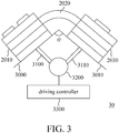
- FIG. 3 is a schematic diagram of a system architecture of an antenna system according to an embodiment of the invention.
- the antenna system 30 in this embodiment includes the antenna array shown in FIG. 2 and is equipped with a control device composed of a supporting frame including supporting segments 3000 and 3010, a driving structure including driving rods 3100 and 3110 and a servo motor 3200, and a driving controller 3300.
- a control device composed of a supporting frame including supporting segments 3000 and 3010, a driving structure including driving rods 3100 and 3110 and a servo motor 3200, and a driving controller 3300.
- the control command may be automatically generated and provided for the driving controller 3300 by deep sensing learning in response to a sensing result of a sensing device, which is included in or external to the antenna system.
- a motion sensor such as a passive infrared (PIR) sensor or a radar sensor senses data of a target angle and/or other motional parameters of an object in the detected region where the antenna system 30 is disposed and conducts a monitoring operation. Then the data of the target angle and/or motional parameters of the object is outputted to the driving controller 3300, and the driving controller 3300 determines how the state of the antenna array is to be changed according to the sensing result. Then the driving controller 3300 issues a control command to have the servo motor 3200 drives the supporting frame 3000 to bend via the driving rods 3100 and/or 3110, thereby adjusting a configuration of the antenna array, e.g. relative positions of the antenna units included in the antenna array.
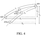
- FIG. 4 schematically illustrates an initial state and a bending state of the antenna array, in which the circles 400, 410, and 420 represent the relative positions of the three antenna units 210, 212 and 214.
- the scheme in FIG. 4 shows that in the initial state, the positions 400 and 420 are different and horizontally apart from each other with a distance X1, and different and vertically apart from each other with a distance Y1.
- the length L1 is the length of the signal transmission line 220 between the positions 400 and 420, wherein the signal transmission line 220 interconnects the three antenna units 210, 212 and 214.
- the antenna unit 210 is originally located at the position 400. It is to be noted that the position 400 is not necessarily a fixed location, and it may be variable in other applications.
- the driving controller 3300 controls the servo motor 3200 to respectively move the locations of the antenna units 212 and 214 from the original positions 410 and 420to the positions 410a and 420a as respectively shown in FIG. 4 . Since the length L2 of the signal transmission line, after being adjusted, will not change and is still equal to the length L1. Accordingly, the horizontal distance between the positions 400 and 420a changes from X1 to X2, and the vertical distance between the positions 400 and 420a changes from Y1 to Y2. As a result, the pattern of the electromagnetic wave field derived from the three antenna units can be adjusted by changing the relative positions of the associated antenna units.
- each of the supporting segment 3000 and 3010 is relatively rigid to maintain a fixed shape, e.g. a planar shape.
- the supporting segment 3000 can be used to secure the structure in the antenna installation region 2010, and the supporting segment 3010 can be used to fix the structure in the antenna installation region 2030.
- the driving rod 3100 is coupled to the supporting segment 3000 and the servo motor 3200, and transmitted to adjust the position of the supporting segment 3000 by the servo motor 3200.
- the driving rod 3110 is coupled to the supporting segment 3010 and the servo motor 3200, and transmitted to adjust the position of the supporting segment 3010 by the servo motor 3200.
- the driving controller 3300 is electrically coupled to the servo motor 3200, and controls the operation of the servo motor 3200 according to preset or dynamically inputted conditions, thereby controlling the motions of the driving rods 3100 and 3110.
- the positions of the supporting segments 3000 and 3010, and the angle ⁇ between the supporting segments 3000 and 3010 will change, so as to change the relative positions of the antenna units 210, 212, and 214. Accordingly, the electromagnetic wave field pattern along with the emitted electromagnetic waves will change as well.
- the layout of the antenna array can be flexibly designed and the relative positions of the array units in the antenna array can be dynamically adjusted to create desired patterns of electromagnetic wave field.
- the present invention may involve in a variety of applications in our daily lives.
- safety of a car equipped with headlights rotating with its steering wheel may be further enhanced by installing an antenna array according to the present invention on the lamp holders of the headlights or any other suitable place where antenna detection is required.
- the configuration of the antenna array can be synchronously determined and adjusted according to the directional rotating degrees of the steering wheel or the headlight(s) to realize more reliable information for driving safety.
- an antenna array according to the present invention may be disposed on one or more gravity sensors (G sensors) in rearview mirrors of a car to provide important driving information for the driver.
- the antenna array according to the present invention may also be used in a camera for detecting or compensating a focus shift problem.
- a configuration of the antenna array e.g. relative positions of the antenna units included in the antenna array
- the adjustment of the relative positions of the antenna units can be readily achieved as a result of a relative motion between portions of the flexible substrate in response a default setting or a dynamic input command.
- a substrate can be made flexible by a variety of ways. For example, it can be accomplished by way of selected material and/or structural design.
Landscapes
- Engineering & Computer Science (AREA)
- Remote Sensing (AREA)
- Variable-Direction Aerials And Aerial Arrays (AREA)
- Details Of Aerials (AREA)
Description
- The present invention relates to an antenna system, and more particular to an antenna system including an antenna array, whose conditions can be dynamically adjusted.
- In many applications, a directional antenna array is often used for sensing the specific directional state of the external environment. For example, a directional array antenna can be used to sense the surrounding obstacles appearing in the specific direction in the driving route of a car. For example,
US 6,885,345 B2 andUS 10,027,014 B2 EP3624354 , which belongs to the state of the art under Article 54(3) EPC, discloses a radio relay device wherein the antenna units are connected to each other via a transmission line that is disposed on a flexible substrate, and two radio ICs convert the signal to the baseband before sending it to the transmission line to avoid EM radiation. - A directional antenna array generally includes a plurality of antennas allocated in a specified manner and combined as an antenna assembly having an overall beam direction associated with respective electromagnetic waves of the antenna units. The circuit board for mounting thereon the antenna units is usually a multilayer printed circuit board (PCB), which is advantageous in stabilizing the overall beam direction of the antenna array due to its stable and non-deformable natures. For example,
US 2010/168727 A1 andUS 2002/024468 A1 disclose fixed configurations of antenna arrays. On the other hand, just because of the stable and non-deformable natures of the multilayer printed circuit board, the beam direction of the antenna array is fixed, and thus the coverage range of the beam is confined. The limited coverage range also means the limited applications, and the structure of antenna arrays would need to be particularly designed in order to properly adjust the coverage range and make better sensing performance. - Therefore, the present invention provides an antenna system including an antenna array, according to claim 1, a control device and a driving mechanism. The antenna array includes a plurality of antenna units disposed on a flexible substrate, wherein a configuration of the flexible substrate is variable so as to change relative positions of at least two of the antenna units. The control device determines the configuration of the flexible substrate according to a default setting or in response to a dynamic input. The driving mechanism is connected between the flexible substrate and the control device for driving the change of the configuration of the flexible substrate in response to a command from the control device.
- The invention will become more readily apparent to those ordinarily skilled in the art after reviewing the following detailed description and accompanying drawings, in which:
-
FIG. 1A is a schematic diagram illustrating an antenna array according to an embodiment of the present invention; - FIG. IB is a schematic diagram illustrating partially an antenna array according to another embodiment of the present invention;
-
FIG. 2 is a schematic cross-sectional view illustrating a partial antenna array according to another embodiment of the present invention; -
FIG. 3 is a schematic diagram illustrating a systematic structure of an antenna system including the antenna array ofFIG. 2 ; -
FIG. 4 is a scheme illustrating an initial state and a bending state of the antenna array in the antenna system ofFIG. 3 ; and -
FIG. 5 is a schematic cross-sectional view illustrating a partial antenna array according to a further embodiment of the present invention. - Please refer to
FIG. 1A , which schematically shows the configuration of an antenna array according to an embodiment of the invention. As shown, theantenna array 10 includes anantenna substrate 100,antenna units 110, andsignal transmission lines 120. Theantenna substrate 100 is defined with two or moreantenna installation regions 1010 and a corresponding number of connectingregions 1020, which interconnect theantenna installation regions 1010 in a flexible manner. The portion of theantenna substrate 100, where the connectingregions 1020 are located, is locally deformable or bendable, thereby making the connectingregions 1020 flexible. Theantenna units 110 includes a plurality ofantenna units antenna installation regions 1010, and each of thesignal transmission lines 120 is disposed in one of the connectingregions 1020. Basically, each of the connectingregions 1020 is disposed for connecting twoantenna installation regions 1010. The layout of theantenna installation regions 1010 and the connectingregions 1020 are specifically designed so that a signal SI coupled to the antenna array can be delivered among any of theantenna units 110 included in theantenna array 10 via conductive wires, which include the conductive wires in the antenna units and other conductive wires in theantenna installation regions 1010, and thesignal transmission lines 120. Theantenna array 10 can thus generate a certain pattern of electromagnetic wave field corresponding to the input signal SI, for communication or detection of the state of the surrounding environment accordingly. On the other hand, a signal from any of theantenna units 110 can also be transmitted out of the antenna array via the conductive wires - It is to be noted that the
signal transmission lines 120, although expressed as straight lines inFIG. 1A , may be configured to be another shape. For example, it may be consistent battlement-shaped, as illustrated inFIG. 1B , polygon-shaped or curve-shaped. Furthermore, as the design requirement of theantenna array 10 changes, e.g. the pattern of the electromagnetic wave field changes, it is feasible to install two of theantenna units 110, e.g. theantenna units 1107 and 1108, in the sameantenna installation region 1010, e.g. theantenna installation region 10108, while having one of theantenna installation regions 1010, e.g. theantenna installation region 10105, vacant without anyantenna unit 110 installed therein. Likewise, as long as signals can be successfully transmitted to each of the designatedantenna units 110, the connectingregions 1020 may be selectively and optionally used for disposing thesignal transmission lines 120. Furthermore, the width of one or each of theconnecting regions 1020 may be the same as or narrower than the width of one or each of theantenna installation regions 1010. The configuration of theantenna array 10 shown inFIG. 1 is only one implementing example of the present invention, and it is not intended to limit the applications of the present invention to the illustrated example. - Next, please refer to
FIG. 2 , which is a cross-sectional view schematically exemplifying the disposition of the antenna units and signal transmission lines on the substrate and the stackup of the substrate. In the embodiment shown inFIG. 2 , threeantenna units antenna units antenna installation region 2010, and theantenna unit 214 is disposed in anotherantenna installation region 2030. The portion of theantenna substrate 100 defined with each of theantenna installation regions separate layers antenna installation region 2010, and fourseparate layers antenna installation region 2030. For forming some of these layers, e.g. theinner layers outer layers signal transmission line 220 is located, forms a flexible orbendable layer 2020. With the above-described specific allocation and distribution of flexible and rigid material, parts of theantenna substrate 100 are inflexible while theoverall antenna substrate 100 exhibits a flexible state. - In this embodiment, the
antenna units uppermost layer 2012 in theantenna installation region 2010, and theantenna unit 214 is disposed on theuppermost layer 2032 in theantenna installation region 2030. Asignal transmission line 220 that transmits signals among theantenna units layers antenna units layers layers antenna installation regions 2010 and/or 2030 to serve as the flexible orbendable layer 2020, or the flexible orbendable layer 2020 may extend into theantenna installation regions 2010 and/or 2030 to function like thelayers 2014 and/or 2034. The smaller thickness of thelayer 2020 than the overall thickness of the composite layers in theantenna installation region space 2021 thereunder for accommodating a flexible or bendable shift from a substrate portion from theantenna installation regions 2010 and/or 2030. - It should be noted that the substrate portions in both the
antenna installation regions antenna installation regions bendable layer 2020 may also be designed to includemultiple layers FIG. 5 . In the embodiment shown inFIG. 2 , thesignal transmission line 220 is disposed within thelayers FIG. 5 , thesignal transmission line 220 is disposed on thelayer 2020b and covered by thelayer 2020a. As shown inFIG. 5 , thelayer 2014 further includes twosub-layers signal transmission line 220 is disposed on thelayer 2014b and covered by thelayer 2014a. - Next, please refer to
FIG. 3 , which is a schematic diagram of a system architecture of an antenna system according to an embodiment of the invention. Theantenna system 30 in this embodiment includes the antenna array shown inFIG. 2 and is equipped with a control device composed of a supporting frame including supportingsegments rods servo motor 3200, and a drivingcontroller 3300. With the configuration as shown, an effect of changing positions of the antenna array and adjusting bending degrees of the flexible substrate according to a control command can be achieved. In an embodiment, the control command may be automatically generated and provided for the drivingcontroller 3300 by deep sensing learning in response to a sensing result of a sensing device, which is included in or external to the antenna system. For example, a motion sensor such as a passive infrared (PIR) sensor or a radar sensor senses data of a target angle and/or other motional parameters of an object in the detected region where theantenna system 30 is disposed and conducts a monitoring operation. Then the data of the target angle and/or motional parameters of the object is outputted to the drivingcontroller 3300, and the drivingcontroller 3300 determines how the state of the antenna array is to be changed according to the sensing result. Then the drivingcontroller 3300 issues a control command to have theservo motor 3200 drives the supportingframe 3000 to bend via the drivingrods 3100 and/or 3110, thereby adjusting a configuration of the antenna array, e.g. relative positions of the antenna units included in the antenna array.FIG. 4 schematically illustrates an initial state and a bending state of the antenna array, in which thecircles antenna units FIG. 4 shows that in the initial state, thepositions signal transmission line 220 between thepositions signal transmission line 220 interconnects the threeantenna units servo motor 3200. As shown, theantenna unit 210 is originally located at theposition 400. It is to be noted that theposition 400 is not necessarily a fixed location, and it may be variable in other applications. The drivingcontroller 3300 controls theservo motor 3200 to respectively move the locations of theantenna units original positions 410 and 420to thepositions FIG. 4 . Since the length L2 of the signal transmission line, after being adjusted, will not change and is still equal to the length L1. Accordingly, the horizontal distance between thepositions positions - In this embodiment, each of the supporting
segment segment 3000 can be used to secure the structure in theantenna installation region 2010, and the supportingsegment 3010 can be used to fix the structure in theantenna installation region 2030. The drivingrod 3100 is coupled to the supportingsegment 3000 and theservo motor 3200, and transmitted to adjust the position of the supportingsegment 3000 by theservo motor 3200. Likewise, the drivingrod 3110 is coupled to the supportingsegment 3010 and theservo motor 3200, and transmitted to adjust the position of the supportingsegment 3010 by theservo motor 3200. The drivingcontroller 3300 is electrically coupled to theservo motor 3200, and controls the operation of theservo motor 3200 according to preset or dynamically inputted conditions, thereby controlling the motions of the drivingrods rods segments segments antenna units - The present invention may involve in a variety of applications in our daily lives. For example, safety of a car equipped with headlights rotating with its steering wheel may be further enhanced by installing an antenna array according to the present invention on the lamp holders of the headlights or any other suitable place where antenna detection is required. The configuration of the antenna array can be synchronously determined and adjusted according to the directional rotating degrees of the steering wheel or the headlight(s) to realize more reliable information for driving safety. In another example, an antenna array according to the present invention may be disposed on one or more gravity sensors (G sensors) in rearview mirrors of a car to provide important driving information for the driver. The antenna array according to the present invention may also be used in a camera for detecting or compensating a focus shift problem.
- In view of the foregoing, by installing antenna units on a flexible substrate to form an antenna array, a configuration of the antenna array, e.g. relative positions of the antenna units included in the antenna array, can be dynamically and finely adjusted to provide a desirable configuration of the antenna array for some specific purpose. The adjustment of the relative positions of the antenna units can be readily achieved as a result of a relative motion between portions of the flexible substrate in response a default setting or a dynamic input command. Furthermore, a substrate can be made flexible by a variety of ways. For example, it can be accomplished by way of selected material and/or structural design.
Claims (10)
- An antenna array, comprising:at least first and second antenna units (110, 1101-1109, 210, 212, 214); anda signal transmission line (120, 220) directly connected to the first and second antenna units (110, 1101-1109, 210, 212, 214) for delivering a signal between the first and second antenna units (110, 1101-1109, 210, 212, 214); anda flexible substrate (100), in which at least first and second antenna installation regions (1010, 10105, 10108, 2010, 2030) are defined for supporting at least the first and second antenna units (110, 1101-1109, 210, 212, 214), respectively, and a connecting region (1020) disposed between the first and second antenna installation regions (1010, 10105, 10108, 2010, 2030) for supporting at least the signal transmission line (120, 220), wherein a substrate portion in each of the first and second antenna installation regions (1010, 10105, 10108, 2010, 2030) includes at least two layers (2012, 2014, 2016, 2018, 2032, 2034, 2036, 2038) stacked in sequence, and characterized by further comprising:
a substrate
portion in the connecting region (1020) configured to be more flexible than the substrate portion in each of the first and second antenna installation regions (1010, 10105, 10108, 2010, 2030) so that the substrate portion in the first antenna installation region (1010, 10105, 10108, 2010, 2030) and the substrate portion in the second antenna installation region (1010, 10105, 10108, 2010, 2030) are dynamically movable relative to each other for adjusting a configuration of the antenna array by driving the substrate portion in the connecting region (1020) to bend. - The antenna array according to claim 1, wherein a specified one of the at least two layers (2014, 2034) of the substrate portion in each of the first and second antenna installation regions (1010, 10105, 10108, 2010, 2030) and the substrate portion (2020) in the connecting region (1020) are made of a flexible material and interconnected as a continuous layer.
- The antenna array according to claim 2, wherein the other one of the least two layers (2012, 2018, 2032, 2038) of the substrate portion in each of the first and second antenna installation regions (1010, 10105, 10108, 2010, 2030) is made of less flexible material than the specified one of the at least two layers (2014, 2034) for installing thereon the first/second antenna unit (110, 1101-1109, 210, 212, 214).
- The antenna array according to claim 1, wherein the substrate portion in the connecting region (1020) is thinner than the substrate portion in each of the first and second antenna installation regions (1010, 10105, 10108, 2010, 2030) such that a space (2021) under the substrate portion in the connecting region (1020) between the substrate portions in the first and second antenna installation regions (1010, 10105, 10108, 2010, 2030) is remained.
- The antenna array according to claim 1, further comprising a third antenna unit (1107/1108, 210/212) supported by the same substrate portion in the first or second antenna installation region (10108, 2010), and interconnected with the first and second antenna units (210/212, 214) by the signal transmission line (120, 220).
- The antenna array according to claim 1, wherein the substrate portion in each of the first and second antenna installation regions (1010, 10105, 10108, 2010, 2030) is implemented with a multilayer printed circuit board.
- The antenna array according to claim 1, wherein the substrate portion in the connecting region (1020) is implemented with single or multiple dielectric layers.
- An antenna system, comprising:an antenna array (10) according to claim 1;a control device (3000, 3010) configured to determine a configuration of the flexible substrate (100) according to a default setting or in response to a dynamic input; anda driving mechanism (3100, 3110, 3200, 3300) connected between the flexible substrate (100) and the control device (3000, 3010) for driving a change of the configuration of the flexible substrate (100) in response to a command from the control device.
- The antenna system according to claim 8, wherein the control device is further configured to determine a relative motion between the substrate portion in the first antenna installation region (1010, 10105, 10108, 2010, 2030) and the substrate portion in the second antenna installation region (1010, 10105, 10108, 2010, 2030) according to the default setting or in response to the dynamic input.
- The antenna system according to claim 8, wherein the driving mechanism (3100, 3110, 3200, 3300) is connected to the substrate portions in the first and second antenna installation regions (1010, 10105, 10108, 2010, 2030) and the control device (3000, 3010) for driving the relative motion in response to the command from the control device.
Applications Claiming Priority (1)
| Application Number | Priority Date | Filing Date | Title |
|---|---|---|---|
| TW107130906A TWI681594B (en) | 2018-09-04 | 2018-09-04 | Array antenna and antenna system with variable sensing direction |
Publications (2)
| Publication Number | Publication Date |
|---|---|
| EP3621155A1 EP3621155A1 (en) | 2020-03-11 |
| EP3621155B1 true EP3621155B1 (en) | 2021-07-07 |
Family
ID=67658754
Family Applications (1)
| Application Number | Title | Priority Date | Filing Date |
|---|---|---|---|
| EP19191631.1A Active EP3621155B1 (en) | 2018-09-04 | 2019-08-14 | Dynamically adjusted antenna system and antenna array included therein |
Country Status (4)
| Country | Link |
|---|---|
| US (1) | US10840580B2 (en) |
| EP (1) | EP3621155B1 (en) |
| CN (1) | CN110875525B (en) |
| TW (1) | TWI681594B (en) |
Families Citing this family (6)
| Publication number | Priority date | Publication date | Assignee | Title |
|---|---|---|---|---|
| TWI746218B (en) * | 2020-10-20 | 2021-11-11 | 鼎天國際股份有限公司 | Flexible soft board radar antenna device with field of view greater than 160 degrees |
| US11552395B2 (en) | 2020-11-20 | 2023-01-10 | Rockwell Collins, Inc. | ESA quadrant mechanical reconfiguration |
| CN113036457B (en) * | 2021-03-22 | 2022-07-22 | 重庆大学 | Flexible antenna array based on microwave energy transmission |
| TWI784680B (en) * | 2021-08-19 | 2022-11-21 | 特崴光波導股份有限公司 | Antenna structure and antenna array structure |
| CN114497974B (en) * | 2022-03-16 | 2025-04-25 | 安捷利(番禺)电子实业有限公司 | An antenna array |
| CN116053785A (en) * | 2022-12-23 | 2023-05-02 | 遵义市气象局 | An Improved Phased Array Antenna |
Citations (1)
| Publication number | Priority date | Publication date | Assignee | Title |
|---|---|---|---|---|
| EP3624354A1 (en) * | 2017-05-10 | 2020-03-18 | Fujikura Ltd. | Wireless relay device |
Family Cites Families (18)
| Publication number | Priority date | Publication date | Assignee | Title |
|---|---|---|---|---|
| US6476773B2 (en) * | 2000-08-18 | 2002-11-05 | Tantivy Communications, Inc. | Printed or etched, folding, directional antenna |
| US6885345B2 (en) * | 2002-11-14 | 2005-04-26 | The Penn State Research Foundation | Actively reconfigurable pixelized antenna systems |
| US7064713B2 (en) * | 2004-09-14 | 2006-06-20 | Lumera Corporation | Multiple element patch antenna and electrical feed network |
| US7442050B1 (en) | 2005-08-29 | 2008-10-28 | Netlist, Inc. | Circuit card with flexible connection for memory module with heat spreader |
| GB0620061D0 (en) | 2006-10-10 | 2006-11-22 | Medical Device Innovations Ltd | Oesophageal treatment apparatus and method |
| WO2009012361A1 (en) | 2007-07-19 | 2009-01-22 | Rambus Inc. | Radio beam forming antenna with electroactive polymer actuator |
| US8626242B2 (en) * | 2009-11-02 | 2014-01-07 | Panasonic Corporation | Adaptive array antenna and wireless communication apparatus including adaptive array antenna |
| US9742077B2 (en) * | 2011-03-15 | 2017-08-22 | Intel Corporation | Mm-wave phased array antenna with beam tilting radiation pattern |
| TWI483468B (en) * | 2011-04-20 | 2015-05-01 | China Steel Corp | Antenna array device |
| WO2013154713A1 (en) * | 2012-04-12 | 2013-10-17 | Unipixel Display, Inc. | Low-visibility antennas based flexographic printing |
| JP5875935B2 (en) * | 2012-05-15 | 2016-03-02 | 株式会社東芝 | Curved array antenna |
| US9225058B2 (en) * | 2013-03-15 | 2015-12-29 | Blackberry Limited | Flex PCB folded antenna |
| DE102014014860B3 (en) * | 2014-10-06 | 2015-09-17 | Audi Ag | Radar sensor assembly and motor vehicle |
| US9548543B2 (en) * | 2015-01-07 | 2017-01-17 | Omega Optics, Inc. | Method for fabricating and packaging an M×N phased-array antenna |
| KR101694261B1 (en) * | 2015-09-09 | 2017-01-23 | 현대자동차주식회사 | An antenna apparatus and a vehicle using the same |
| CN106356647A (en) * | 2016-11-04 | 2017-01-25 | 中国科学院深圳先进技术研究院 | Bending antenna array and layout method thereof |
| CN107887686B (en) * | 2017-03-30 | 2019-02-26 | 比亚迪股份有限公司 | Vehicle Array Radar Antennas and Lamps |
| US11088468B2 (en) * | 2017-12-28 | 2021-08-10 | Samsung Electro-Mechanics Co., Ltd. | Antenna module |
-
2018
- 2018-09-04 TW TW107130906A patent/TWI681594B/en active
- 2018-11-09 CN CN201811331811.4A patent/CN110875525B/en active Active
-
2019
- 2019-07-31 US US16/527,320 patent/US10840580B2/en active Active
- 2019-08-14 EP EP19191631.1A patent/EP3621155B1/en active Active
Patent Citations (1)
| Publication number | Priority date | Publication date | Assignee | Title |
|---|---|---|---|---|
| EP3624354A1 (en) * | 2017-05-10 | 2020-03-18 | Fujikura Ltd. | Wireless relay device |
Also Published As
| Publication number | Publication date |
|---|---|
| EP3621155A1 (en) | 2020-03-11 |
| US20200076047A1 (en) | 2020-03-05 |
| TW202011639A (en) | 2020-03-16 |
| US10840580B2 (en) | 2020-11-17 |
| CN110875525B (en) | 2021-04-09 |
| TWI681594B (en) | 2020-01-01 |
| CN110875525A (en) | 2020-03-10 |
Similar Documents
| Publication | Publication Date | Title |
|---|---|---|
| US10840580B2 (en) | Dynamically adjusted antenna system and antenna array included therein | |
| US20070030208A1 (en) | Cellular antenna and systems and methods therefor | |
| JP6876402B2 (en) | Phased array antenna system with modular control and monitoring architecture | |
| JP6344297B2 (en) | Imaging device and printed circuit board used therefor | |
| JP7283482B2 (en) | Antenna module and vehicle | |
| JP7092152B2 (en) | Antenna module and vehicle | |
| JP2022067597A (en) | Flexible plate-based radar antenna device with field of view over 160 degrees | |
| US10608330B2 (en) | Method and apparatus to conceal near transparent conductors | |
| KR20240090520A (en) | Antenna module placed in vehicle | |
| US20140028514A1 (en) | Low cost, high-performance, switched multi-feed steerable antenna system | |
| US6970133B2 (en) | Antenna system and method of using same | |
| KR102581461B1 (en) | Radar module and automotive radar apparatus having the same | |
| KR20000023616A (en) | Radar Sensor for a vehicle | |
| JP4504933B2 (en) | Antenna device | |
| KR20240024393A (en) | Driver assistance apparatus | |
| CN114094307B (en) | Antenna device and vehicle | |
| EP3633403B1 (en) | Object sensor including pitch compensation | |
| CN116349400A (en) | Installations of the lighting technology network | |
| CN211417103U (en) | Vehicle side direction rear-view mirror and vehicle | |
| KR102938454B1 (en) | Glass substrate module placed in a vehicle | |
| US20240012101A1 (en) | Asymmetric wide-angle radar module | |
| KR101458700B1 (en) | Radar Apparatus for a Vehicle and Radar Antenna for the Radar Apparatus | |
| JP2021057868A (en) | Radar antenna device | |
| JP2008278066A (en) | Antenna and intrusion detection sensor | |
| JP6814657B2 (en) | Antenna device and manufacturing method of antenna device |
Legal Events
| Date | Code | Title | Description |
|---|---|---|---|
| PUAI | Public reference made under article 153(3) epc to a published international application that has entered the european phase |
Free format text: ORIGINAL CODE: 0009012 |
|
| STAA | Information on the status of an ep patent application or granted ep patent |
Free format text: STATUS: REQUEST FOR EXAMINATION WAS MADE |
|
| 17P | Request for examination filed |
Effective date: 20191203 |
|
| AK | Designated contracting states |
Kind code of ref document: A1 Designated state(s): AL AT BE BG CH CY CZ DE DK EE ES FI FR GB GR HR HU IE IS IT LI LT LU LV MC MK MT NL NO PL PT RO RS SE SI SK SM TR |
|
| AX | Request for extension of the european patent |
Extension state: BA ME |
|
| RBV | Designated contracting states (corrected) |
Designated state(s): AL AT BE BG CH CY CZ DE DK EE ES FI FR GB GR HR HU IE IS IT LI LT LU LV MC MK MT NL NO PL PT RO RS SE SI SK SM TR |
|
| GRAP | Despatch of communication of intention to grant a patent |
Free format text: ORIGINAL CODE: EPIDOSNIGR1 |
|
| STAA | Information on the status of an ep patent application or granted ep patent |
Free format text: STATUS: GRANT OF PATENT IS INTENDED |
|
| INTG | Intention to grant announced |
Effective date: 20210223 |
|
| GRAS | Grant fee paid |
Free format text: ORIGINAL CODE: EPIDOSNIGR3 |
|
| GRAA | (expected) grant |
Free format text: ORIGINAL CODE: 0009210 |
|
| STAA | Information on the status of an ep patent application or granted ep patent |
Free format text: STATUS: THE PATENT HAS BEEN GRANTED |
|
| AK | Designated contracting states |
Kind code of ref document: B1 Designated state(s): AL AT BE BG CH CY CZ DE DK EE ES FI FR GB GR HR HU IE IS IT LI LT LU LV MC MK MT NL NO PL PT RO RS SE SI SK SM TR |
|
| REG | Reference to a national code |
Ref country code: GB Ref legal event code: FG4D |
|
| REG | Reference to a national code |
Ref country code: AT Ref legal event code: REF Ref document number: 1409476 Country of ref document: AT Kind code of ref document: T Effective date: 20210715 |
|
| REG | Reference to a national code |
Ref country code: DE Ref legal event code: R096 Ref document number: 602019005888 Country of ref document: DE |
|
| REG | Reference to a national code |
Ref country code: IE Ref legal event code: FG4D |
|
| REG | Reference to a national code |
Ref country code: LT Ref legal event code: MG9D |
|
| REG | Reference to a national code |
Ref country code: NL Ref legal event code: MP Effective date: 20210707 |
|
| REG | Reference to a national code |
Ref country code: AT Ref legal event code: MK05 Ref document number: 1409476 Country of ref document: AT Kind code of ref document: T Effective date: 20210707 |
|
| PG25 | Lapsed in a contracting state [announced via postgrant information from national office to epo] |
Ref country code: HR Free format text: LAPSE BECAUSE OF FAILURE TO SUBMIT A TRANSLATION OF THE DESCRIPTION OR TO PAY THE FEE WITHIN THE PRESCRIBED TIME-LIMIT Effective date: 20210707 Ref country code: NO Free format text: LAPSE BECAUSE OF FAILURE TO SUBMIT A TRANSLATION OF THE DESCRIPTION OR TO PAY THE FEE WITHIN THE PRESCRIBED TIME-LIMIT Effective date: 20211007 Ref country code: NL Free format text: LAPSE BECAUSE OF FAILURE TO SUBMIT A TRANSLATION OF THE DESCRIPTION OR TO PAY THE FEE WITHIN THE PRESCRIBED TIME-LIMIT Effective date: 20210707 Ref country code: PT Free format text: LAPSE BECAUSE OF FAILURE TO SUBMIT A TRANSLATION OF THE DESCRIPTION OR TO PAY THE FEE WITHIN THE PRESCRIBED TIME-LIMIT Effective date: 20211108 Ref country code: LT Free format text: LAPSE BECAUSE OF FAILURE TO SUBMIT A TRANSLATION OF THE DESCRIPTION OR TO PAY THE FEE WITHIN THE PRESCRIBED TIME-LIMIT Effective date: 20210707 Ref country code: AT Free format text: LAPSE BECAUSE OF FAILURE TO SUBMIT A TRANSLATION OF THE DESCRIPTION OR TO PAY THE FEE WITHIN THE PRESCRIBED TIME-LIMIT Effective date: 20210707 Ref country code: BG Free format text: LAPSE BECAUSE OF FAILURE TO SUBMIT A TRANSLATION OF THE DESCRIPTION OR TO PAY THE FEE WITHIN THE PRESCRIBED TIME-LIMIT Effective date: 20211007 Ref country code: SE Free format text: LAPSE BECAUSE OF FAILURE TO SUBMIT A TRANSLATION OF THE DESCRIPTION OR TO PAY THE FEE WITHIN THE PRESCRIBED TIME-LIMIT Effective date: 20210707 Ref country code: RS Free format text: LAPSE BECAUSE OF FAILURE TO SUBMIT A TRANSLATION OF THE DESCRIPTION OR TO PAY THE FEE WITHIN THE PRESCRIBED TIME-LIMIT Effective date: 20210707 Ref country code: ES Free format text: LAPSE BECAUSE OF FAILURE TO SUBMIT A TRANSLATION OF THE DESCRIPTION OR TO PAY THE FEE WITHIN THE PRESCRIBED TIME-LIMIT Effective date: 20210707 Ref country code: FI Free format text: LAPSE BECAUSE OF FAILURE TO SUBMIT A TRANSLATION OF THE DESCRIPTION OR TO PAY THE FEE WITHIN THE PRESCRIBED TIME-LIMIT Effective date: 20210707 |
|
| PG25 | Lapsed in a contracting state [announced via postgrant information from national office to epo] |
Ref country code: PL Free format text: LAPSE BECAUSE OF FAILURE TO SUBMIT A TRANSLATION OF THE DESCRIPTION OR TO PAY THE FEE WITHIN THE PRESCRIBED TIME-LIMIT Effective date: 20210707 Ref country code: LV Free format text: LAPSE BECAUSE OF FAILURE TO SUBMIT A TRANSLATION OF THE DESCRIPTION OR TO PAY THE FEE WITHIN THE PRESCRIBED TIME-LIMIT Effective date: 20210707 Ref country code: GR Free format text: LAPSE BECAUSE OF FAILURE TO SUBMIT A TRANSLATION OF THE DESCRIPTION OR TO PAY THE FEE WITHIN THE PRESCRIBED TIME-LIMIT Effective date: 20211008 |
|
| REG | Reference to a national code |
Ref country code: DE Ref legal event code: R097 Ref document number: 602019005888 Country of ref document: DE |
|
| REG | Reference to a national code |
Ref country code: BE Ref legal event code: MM Effective date: 20210831 |
|
| PG25 | Lapsed in a contracting state [announced via postgrant information from national office to epo] |
Ref country code: DK Free format text: LAPSE BECAUSE OF FAILURE TO SUBMIT A TRANSLATION OF THE DESCRIPTION OR TO PAY THE FEE WITHIN THE PRESCRIBED TIME-LIMIT Effective date: 20210707 |
|
| PLBE | No opposition filed within time limit |
Free format text: ORIGINAL CODE: 0009261 |
|
| STAA | Information on the status of an ep patent application or granted ep patent |
Free format text: STATUS: NO OPPOSITION FILED WITHIN TIME LIMIT |
|
| PG25 | Lapsed in a contracting state [announced via postgrant information from national office to epo] |
Ref country code: SM Free format text: LAPSE BECAUSE OF FAILURE TO SUBMIT A TRANSLATION OF THE DESCRIPTION OR TO PAY THE FEE WITHIN THE PRESCRIBED TIME-LIMIT Effective date: 20210707 Ref country code: SK Free format text: LAPSE BECAUSE OF FAILURE TO SUBMIT A TRANSLATION OF THE DESCRIPTION OR TO PAY THE FEE WITHIN THE PRESCRIBED TIME-LIMIT Effective date: 20210707 Ref country code: RO Free format text: LAPSE BECAUSE OF FAILURE TO SUBMIT A TRANSLATION OF THE DESCRIPTION OR TO PAY THE FEE WITHIN THE PRESCRIBED TIME-LIMIT Effective date: 20210707 Ref country code: MC Free format text: LAPSE BECAUSE OF FAILURE TO SUBMIT A TRANSLATION OF THE DESCRIPTION OR TO PAY THE FEE WITHIN THE PRESCRIBED TIME-LIMIT Effective date: 20210707 Ref country code: LU Free format text: LAPSE BECAUSE OF NON-PAYMENT OF DUE FEES Effective date: 20210814 Ref country code: EE Free format text: LAPSE BECAUSE OF FAILURE TO SUBMIT A TRANSLATION OF THE DESCRIPTION OR TO PAY THE FEE WITHIN THE PRESCRIBED TIME-LIMIT Effective date: 20210707 Ref country code: CZ Free format text: LAPSE BECAUSE OF FAILURE TO SUBMIT A TRANSLATION OF THE DESCRIPTION OR TO PAY THE FEE WITHIN THE PRESCRIBED TIME-LIMIT Effective date: 20210707 Ref country code: AL Free format text: LAPSE BECAUSE OF FAILURE TO SUBMIT A TRANSLATION OF THE DESCRIPTION OR TO PAY THE FEE WITHIN THE PRESCRIBED TIME-LIMIT Effective date: 20210707 |
|
| 26N | No opposition filed |
Effective date: 20220408 |
|
| PG25 | Lapsed in a contracting state [announced via postgrant information from national office to epo] |
Ref country code: IT Free format text: LAPSE BECAUSE OF FAILURE TO SUBMIT A TRANSLATION OF THE DESCRIPTION OR TO PAY THE FEE WITHIN THE PRESCRIBED TIME-LIMIT Effective date: 20210707 Ref country code: IE Free format text: LAPSE BECAUSE OF NON-PAYMENT OF DUE FEES Effective date: 20210814 Ref country code: BE Free format text: LAPSE BECAUSE OF NON-PAYMENT OF DUE FEES Effective date: 20210831 |
|
| REG | Reference to a national code |
Ref country code: CH Ref legal event code: PL |
|
| PG25 | Lapsed in a contracting state [announced via postgrant information from national office to epo] |
Ref country code: LI Free format text: LAPSE BECAUSE OF NON-PAYMENT OF DUE FEES Effective date: 20220831 Ref country code: CH Free format text: LAPSE BECAUSE OF NON-PAYMENT OF DUE FEES Effective date: 20220831 |
|
| PG25 | Lapsed in a contracting state [announced via postgrant information from national office to epo] |
Ref country code: CY Free format text: LAPSE BECAUSE OF FAILURE TO SUBMIT A TRANSLATION OF THE DESCRIPTION OR TO PAY THE FEE WITHIN THE PRESCRIBED TIME-LIMIT Effective date: 20210707 |
|
| PG25 | Lapsed in a contracting state [announced via postgrant information from national office to epo] |
Ref country code: HU Free format text: LAPSE BECAUSE OF FAILURE TO SUBMIT A TRANSLATION OF THE DESCRIPTION OR TO PAY THE FEE WITHIN THE PRESCRIBED TIME-LIMIT; INVALID AB INITIO Effective date: 20190814 |
|
| PG25 | Lapsed in a contracting state [announced via postgrant information from national office to epo] |
Ref country code: MK Free format text: LAPSE BECAUSE OF FAILURE TO SUBMIT A TRANSLATION OF THE DESCRIPTION OR TO PAY THE FEE WITHIN THE PRESCRIBED TIME-LIMIT Effective date: 20210707 |
|
| PG25 | Lapsed in a contracting state [announced via postgrant information from national office to epo] |
Ref country code: MT Free format text: LAPSE BECAUSE OF FAILURE TO SUBMIT A TRANSLATION OF THE DESCRIPTION OR TO PAY THE FEE WITHIN THE PRESCRIBED TIME-LIMIT Effective date: 20210707 |
|
| PGFP | Annual fee paid to national office [announced via postgrant information from national office to epo] |
Ref country code: GB Payment date: 20250610 Year of fee payment: 7 |
|
| PGFP | Annual fee paid to national office [announced via postgrant information from national office to epo] |
Ref country code: FR Payment date: 20250610 Year of fee payment: 7 |
|
| PGFP | Annual fee paid to national office [announced via postgrant information from national office to epo] |
Ref country code: DE Payment date: 20250827 Year of fee payment: 7 |
|
| PG25 | Lapsed in a contracting state [announced via postgrant information from national office to epo] |
Ref country code: TR Free format text: LAPSE BECAUSE OF FAILURE TO SUBMIT A TRANSLATION OF THE DESCRIPTION OR TO PAY THE FEE WITHIN THE PRESCRIBED TIME-LIMIT Effective date: 20210707 |