EP3621090A1 - A coil actuator for low and medium voltage applications - Google Patents
A coil actuator for low and medium voltage applications Download PDFInfo
- Publication number
- EP3621090A1 EP3621090A1 EP18192708.8A EP18192708A EP3621090A1 EP 3621090 A1 EP3621090 A1 EP 3621090A1 EP 18192708 A EP18192708 A EP 18192708A EP 3621090 A1 EP3621090 A1 EP 3621090A1
- Authority
- EP
- European Patent Office
- Prior art keywords
- input
- sub
- reference value
- input current
- pwm controller
- Prior art date
- Legal status (The legal status is an assumption and is not a legal conclusion. Google has not performed a legal analysis and makes no representation as to the accuracy of the status listed.)
- Granted
Links
Images


Classifications
-
- H—ELECTRICITY
- H02—GENERATION; CONVERSION OR DISTRIBUTION OF ELECTRIC POWER
- H02P—CONTROL OR REGULATION OF ELECTRIC MOTORS, ELECTRIC GENERATORS OR DYNAMO-ELECTRIC CONVERTERS; CONTROLLING TRANSFORMERS, REACTORS OR CHOKE COILS
- H02P25/00—Arrangements or methods for the control of AC motors characterised by the kind of AC motor or by structural details
- H02P25/02—Arrangements or methods for the control of AC motors characterised by the kind of AC motor or by structural details characterised by the kind of motor
- H02P25/032—Reciprocating, oscillating or vibrating motors
- H02P25/034—Voice coil motors
-
- H—ELECTRICITY
- H01—ELECTRIC ELEMENTS
- H01F—MAGNETS; INDUCTANCES; TRANSFORMERS; SELECTION OF MATERIALS FOR THEIR MAGNETIC PROPERTIES
- H01F7/00—Magnets
- H01F7/06—Electromagnets; Actuators including electromagnets
- H01F7/064—Circuit arrangements for actuating electromagnets
-
- H—ELECTRICITY
- H01—ELECTRIC ELEMENTS
- H01F—MAGNETS; INDUCTANCES; TRANSFORMERS; SELECTION OF MATERIALS FOR THEIR MAGNETIC PROPERTIES
- H01F7/00—Magnets
- H01F7/06—Electromagnets; Actuators including electromagnets
- H01F7/08—Electromagnets; Actuators including electromagnets with armatures
- H01F7/081—Magnetic constructions
-
- H—ELECTRICITY
- H01—ELECTRIC ELEMENTS
- H01F—MAGNETS; INDUCTANCES; TRANSFORMERS; SELECTION OF MATERIALS FOR THEIR MAGNETIC PROPERTIES
- H01F7/00—Magnets
- H01F7/06—Electromagnets; Actuators including electromagnets
- H01F7/08—Electromagnets; Actuators including electromagnets with armatures
- H01F7/18—Circuit arrangements for obtaining desired operating characteristics, e.g. for slow operation, for sequential energisation of windings, for high-speed energisation of windings
-
- H—ELECTRICITY
- H01—ELECTRIC ELEMENTS
- H01F—MAGNETS; INDUCTANCES; TRANSFORMERS; SELECTION OF MATERIALS FOR THEIR MAGNETIC PROPERTIES
- H01F7/00—Magnets
- H01F7/06—Electromagnets; Actuators including electromagnets
- H01F7/08—Electromagnets; Actuators including electromagnets with armatures
- H01F7/18—Circuit arrangements for obtaining desired operating characteristics, e.g. for slow operation, for sequential energisation of windings, for high-speed energisation of windings
- H01F7/1844—Monitoring or fail-safe circuits
-
- H—ELECTRICITY
- H02—GENERATION; CONVERSION OR DISTRIBUTION OF ELECTRIC POWER
- H02P—CONTROL OR REGULATION OF ELECTRIC MOTORS, ELECTRIC GENERATORS OR DYNAMO-ELECTRIC CONVERTERS; CONTROLLING TRANSFORMERS, REACTORS OR CHOKE COILS
- H02P7/00—Arrangements for regulating or controlling the speed or torque of electric DC motors
- H02P7/02—Arrangements for regulating or controlling the speed or torque of electric DC motors the DC motors being of the linear type
- H02P7/025—Arrangements for regulating or controlling the speed or torque of electric DC motors the DC motors being of the linear type the DC motors being of the moving coil type, e.g. voice coil motors
-
- H—ELECTRICITY
- H03—ELECTRONIC CIRCUITRY
- H03K—PULSE TECHNIQUE
- H03K3/00—Circuits for generating electric pulses; Monostable, bistable or multistable circuits
- H03K3/01—Details
- H03K3/017—Adjustment of width or dutycycle of pulses
-
- H—ELECTRICITY
- H01—ELECTRIC ELEMENTS
- H01F—MAGNETS; INDUCTANCES; TRANSFORMERS; SELECTION OF MATERIALS FOR THEIR MAGNETIC PROPERTIES
- H01F7/00—Magnets
- H01F7/06—Electromagnets; Actuators including electromagnets
- H01F7/08—Electromagnets; Actuators including electromagnets with armatures
- H01F7/18—Circuit arrangements for obtaining desired operating characteristics, e.g. for slow operation, for sequential energisation of windings, for high-speed energisation of windings
- H01F7/1844—Monitoring or fail-safe circuits
- H01F2007/1861—Monitoring or fail-safe circuits using derivative of measured variable
-
- H—ELECTRICITY
- H01—ELECTRIC ELEMENTS
- H01F—MAGNETS; INDUCTANCES; TRANSFORMERS; SELECTION OF MATERIALS FOR THEIR MAGNETIC PROPERTIES
- H01F7/00—Magnets
- H01F7/06—Electromagnets; Actuators including electromagnets
- H01F7/08—Electromagnets; Actuators including electromagnets with armatures
- H01F7/18—Circuit arrangements for obtaining desired operating characteristics, e.g. for slow operation, for sequential energisation of windings, for high-speed energisation of windings
- H01F2007/1888—Circuit arrangements for obtaining desired operating characteristics, e.g. for slow operation, for sequential energisation of windings, for high-speed energisation of windings using pulse width modulation
-
- H—ELECTRICITY
- H01—ELECTRIC ELEMENTS
- H01H—ELECTRIC SWITCHES; RELAYS; SELECTORS; EMERGENCY PROTECTIVE DEVICES
- H01H33/00—High-tension or heavy-current switches with arc-extinguishing or arc-preventing means
- H01H33/02—Details
- H01H33/28—Power arrangements internal to the switch for operating the driving mechanism
- H01H33/38—Power arrangements internal to the switch for operating the driving mechanism using electromagnet
-
- H—ELECTRICITY
- H01—ELECTRIC ELEMENTS
- H01H—ELECTRIC SWITCHES; RELAYS; SELECTORS; EMERGENCY PROTECTIVE DEVICES
- H01H47/00—Circuit arrangements not adapted to a particular application of the relay and designed to obtain desired operating characteristics or to provide energising current
- H01H47/22—Circuit arrangements not adapted to a particular application of the relay and designed to obtain desired operating characteristics or to provide energising current for supplying energising current for relay coil
- H01H47/32—Energising current supplied by semiconductor device
- H01H47/325—Energising current supplied by semiconductor device by switching regulator
Definitions
- the present invention relates to a coil actuator for low and medium voltage applications.
- the term "low voltage” is referred to operating voltages lower than 1 kV AC whereas the term “medium voltage” is referred to operating voltages higher than IkV AC up to some tens of kV, e.g. 72 kV AC.
- Coil actuators are frequently used in medium and low voltage apparatuses, for instance in low or medium voltage circuit breakers, disconnectors, contactors, for a wide variety of applications. As an example, these devices are widely used to release or lock mechanical parts of spring-actuated circuit breakers, following an opening or closing command.
- most traditional coil actuators normally comprise an electromagnet provided with a pair of distinct windings and a driving electronics capable of selectively energizing said windings to move the anchor of the electromagnet from a rest position to an actuated position (launch operation) or maintain said anchor in said actuated position (hold operation) or to allow the return of said anchor in said rest position (release operation).
- single coil actuators having an electromagnet provided with a single coil winding
- a driving electronics controls an excitation current circulating in the electromagnet so that the excitation current takes an average operating level for a certain time interval.
- the driving electronics may control the excitation current circulating in the electromagnet in such a way that this latter takes a predetermined launch level or a predetermined hold level for said excitation current for a corresponding time interval, in which a launch operation or a hold operation of the electromagnet is carried out.
- the selection of the average operating level to be obtained for the excitation current is carried out depending on the behavior of an input voltage received by the driving electronics.
- the above-mentioned driving electronics normally includes capacitors (generally of the electrolytic type) to store electric energy necessary to properly drive the electromagnet, particularly when the input voltage is variable, for example because it has a pulsed or a rectified sinusoidal waveform.
- the main aim of the present invention to provide a coil actuator for medium and low voltage applications that solves the above-mentioned problems.
- the present invention relates to a coil actuator for low and medium voltage applications according to the following claim 1 and related dependent claims.
- the coil actuator comprises at least a coil electromagnet, which is provided with a single coil winding and a movable anchor, and a power and control unit comprising a power circuit and a PWM controller.
- the power circuit is operatively coupled with the coil electromagnet and it comprises input terminals, at which it receives an input voltage.
- the PWM controller is operatively coupled with the power circuit to control an input current flowing through the power circuit to obtain an average operating level selected for an excitation current feeding said coil electromagnet.
- the PWM controller is adapted to set a plurality of reference values for said input current to control said input current and obtain the average operating level selected for said excitation current.
- Each reference value for said input current is selected among said plurality of reference values depending on the behavior of said input voltage.
- the PWM controller is adapted to select:
- the PWM controller is adapted to select:
- the power and control unit comprises first sensing means adapted to provide first detection signals indicative of a behavior of said input voltage.
- the PWM controller is adapted to receive and process said first detection signals.
- the power and control unit comprises second sensing means adapted to provide second detection signals indicative of a behavior of said input current.
- the PWM controller is adapted to receive and process said second detection signals.
- the power circuit comprises a discharge circuit, which is electrically connected with a first input terminal and an electric node of said power circuit in parallel with said coil electromagnet.
- the power circuit comprises a switch circuit, which is electrically connected with said electric node and a second input terminal of said power circuit.
- the switch circuit comprises at least a power switch.
- the PWM controller is operatively coupled with said switch circuit to control operation of said at least a power switch.
- Said at least a power switch comprises a power switch adapted to switch with a given switch frequency between a conduction state, at which said input current is allowed to flow through said power circuit, and an interdiction state, at which said input current is interrupted.
- a discharge current flows along said discharge circuit, when said power switch is in a conduction state.
- the PWM controller is adapted to control a duty-cycle value of said power switch in order to make said input current to reach a reference value set for said input current.
- the PWM controller is adapted to select an average operating level to be obtained for the excitation current and a corresponding plurality of reference values to be set for said input current depending on one or more characteristic parameters of said input voltage.
- the PWM controller is adapted to select the average operating level to be obtained for said excitation current and a corresponding plurality of reference values to be set for said input current in response to control signals received at a communication port.
- the present invention relate to a low or medium voltage apparatus according to claim 12.
- the present invention relates to a coil actuator 1 for low and medium voltage applications.
- the coil actuator 1 is intended to be installed in low or medium voltage apparatuses, such as low or medium voltage circuit breakers, disconnectors, contactors, and the like.
- the coil actuator 1 conveniently comprises a casing (not shown) defining a volume in which the internal components of said coil actuator are accommodated.
- the coil actuator 1 comprises a coil electromagnet 2 provided with a single coil winding 21 and a movable anchor 22.
- the movable anchor 22 is conveniently movable between a rest position and a launch position upon the application of an actuation force.
- the movable anchor 22 is moved from the rest position to the launch position (launch operation) by a magnetic force due to a magnetic flux generated by an excitation current I E flowing along the coil electromagnet 2, more precisely along the single winding 21 of this latter.
- the movable anchor 22 is moved from the launch position to the rest position (release operation) by a mechanical force exerted by mechanical means (not shown) included in the coil electromagnet 2, such as a spring suitably charged during the launch operation of the coil electromagnet.
- the movable anchor 22 cannot stably maintain the above-mentioned launch position. To maintain this condition, an excitation current I E has still to flow along the coil electromagnet 2 (hold operation). Once such an excitation current is interrupted or sufficiently reduced, the movable anchor 22 returns in the rest position due to the opposing force exerted by the above-mentioned mechanical means.
- the movable anchor 22 when the coil actuator 1 is installed in a low or medium voltage apparatus, the movable anchor 22 is operatively coupled with a kinematic mechanism of said apparatus. As an example, when the coil actuator 1 is installed in a medium voltage circuit breaker, the movable anchor 22 may be operatively coupled with the primary command chain of the circuit breaker.
- the coil actuator 1 comprises a power and control unit 3 operatively coupled with the coil electromagnet 2 to suitably control the operation of this latter.
- the power and control unit 3 comprises a power circuit 4 and a PWM controller 6.
- the power circuit 4 is operatively coupled with the coil electromagnet 2 to drive this latter upon receiving an input voltage V IN at suitable input terminals T1, T2.
- the coil electromagnet 2 can be fed by a suitable excitation current I E and an operation of the coil electromagnet 2 can be carried out.
- the input voltage V IN has a DC waveform.
- the input voltage V IN has a rectified full-wave sinusoidal waveform having a given operating frequency (e.g. 50 Hz).
- the input voltage V IN may have different waveforms, such as a rectified half-wave sinusoidal waveform, a pulsed waveform or a continuous waveform.
- the power and control unit 3 comprises first sensing means 5 (e.g. a resistive divider) adapted to provide first detection signals S1 indicative of a behavior of the input voltage V IN received by the power circuit 4.
- an input current I IN may flow through the power circuit 4, when an input voltage V IN is supplied to this latter.
- the power and control unit 3 comprises second sensing means 7 (e.g. a resistive shunt) adapted to provide second detection signals S2 indicative of a behavior of the input voltage I IN received by the power circuit 4.
- second sensing means 7 e.g. a resistive shunt
- the PWM controller 6 is operatively coupled with the power circuit 4 to control the operation of this latter.
- the PWM controller 6 is adapted to control the input current I IN flowing through the power circuit 4.
- the PWM controller 6 is operatively coupled with the first sensing means 5 in order to receive and process the first detection signals S1, and possibly, with the second sensing means 7 in order to receive and process the second detection signals S2.
- the PWM controller 6 may include one or more computerized units (e.g. microprocessors) configured to execute software instructions to carry out the functionalities provided for said controller.
- the PWM controller 6 may be may be realized according to solutions of known type and it will be hereinafter described only for the aspects relevant to the invention, for the sake of brevity.
- the coil actuator 1 comprises or is operatively connected with a further control unit 8 adapted to interact with the power and control unit 3, for example with the PWM controller 6.
- the control unit 8 may include one or more computerized units (e.g. microprocessors) configured to execute software instructions to carry out the functionalities provided for said control unit.
- the control unit 8 may be realized according to solutions of known type and it will be hereinafter described only for the aspects relevant to the invention, for the sake of brevity.
- the coil actuator 1 comprises a power supply unit 9 operatively coupled with the power and control unit 3 and, possibly, with the control unit 8, to feed these latter units.
- the power supply unit 9 is adapted to provide the input voltage V IN received by the power circuit 4 of the power and control unit 3.
- the power supply stage 9 comprises a power supply circuit (not shown) adapted to receive a power supply voltage from a power supply source (e.g. an electric line).
- a power supply source e.g. an electric line
- the power supply stage 9 comprises a filter circuit (e.g. a LC filter - not shown) that may be configured to cut high frequency current components (possibly generated by the PWM controller 6) or other disturbances coming from the power supply source.
- a filter circuit e.g. a LC filter - not shown
- the filter circuit may be configured to cut high frequency current components (possibly generated by the PWM controller 6) or other disturbances coming from the power supply source.
- the power supply stage 9 comprises a rectifier circuit (e.g. a circuit bridge - not shown) to convert the power supply voltage (e.g. a sinusoidal voltage) provided by the above-mentioned power supply circuit into a suitable input voltage V IN (e.g. a rectified sinusoidal voltage) to be received by the by the power circuit 4 of the power and control unit 3.
- a rectifier circuit e.g. a circuit bridge - not shown
- V IN e.g. a rectified sinusoidal voltage
- the power supply stage 9 may further comprise additional power supply circuitry (not shown) to feed specific components of the coil actuator (e.g. the PWM controller 6 and the control unit 8) with suitable power supply voltages.
- the operation of the power supply stage 9 may be controlled by the further control unit 8, at least for what concerning the feeding of the power and control unit 3.
- the power supply stage 9 may be realized according to solutions of known type and it will be hereinafter described only for the aspects relevant to the invention, for the sake of brevity.
- the power circuit 4 comprises a first input terminal T1 and a second input terminal T2, at which it receives the input voltage V IN and, possibly, the input current I IN from the power supply unit 9.
- the power circuit 4 comprises a switch circuit 41 and a discharge circuit 42.
- the power circuit 4 comprises an intermediate electric node T3 at which the electromagnet 2, the switch circuit 41 and the discharge circuit 42 are electrically connected.
- the discharge circuit 42 is electrically connected in parallel with the electromagnet 2 (more precisely with the winding 21 of this latter) between the first input terminal T1 and the electric node T3.
- the discharge circuit 42 is designed to allow the equivalent inductance formed by the electromagnet 2 to discharge when this latter is not fed by the input current I IN .
- the discharge circuit 42 comprises a free-wheeling device suitably arranged to allow the circulation of a discharge current I D when the equivalent inductance formed by the electromagnet 2 is subject to discharge.
- said free-wheeling device comprises a free-wheeling diode 420 (which may be of conventional type) having its anode and cathode electrically connected respectively with the electric node T3 and the first input terminal T1.
- a free-wheeling diode 420 (which may be of conventional type) having its anode and cathode electrically connected respectively with the electric node T3 and the first input terminal T1.
- the switch circuit 41 is electrically connected in series with the parallel group formed by the discharge circuit 42 and the coil electromagnet 2.
- the switch circuit 41 is electrically connected between the electric node T3 and the second input terminal T2.
- the switch circuit 41 is designed to allow/prevent the input current I IN (which is received by the power circuit 4 when the input voltage V IN is applied at its input terminals T1, T2) to feed the coil electromagnet 2.
- the switch circuit 41 comprises at least power switch 410.
- said at least a power switch comprises a power switch 410, which may be of conventional type, for example a power MOSFET or BJT.
- the power switch 410 has its drain or collector terminal and its source or emitter terminal electrically connected respectively with the electric node T3 and the second input terminal T2.
- the power switch 410 is conveniently adapted to switch with a given switch frequency between a conduction state and an interdiction state.
- the above-mentioned switch frequency is normally very higher than the operating frequency of the electric quantities characterizing the power circuit 4.
- the switching frequency of said power switch may of 10 kHz whereas the input voltage V IN may have an operating frequency of some tens of Hz.
- the input current I IN is allowed to flow through the power circuit 4, more precisely along the electromagnet 2 passing through said power switch and the input terminals T1, T2. In this case, the equivalent inductance formed by the electromagnet 2 is charged. Additionally, the free-wheeling diode 420 is in an interdiction state and no currents will flow through it (with the exception of small leakage currents).
- the power switch 410 When the power switch 410 is in an interdiction state, the input current I IN is interrupted. Thus, no currents will pass through it (with the exception of small leakage currents) and the input terminals T1, T2. In this case, the free-wheeling diode 420 is in a conduction state and a discharge current I D will flow through the discharge circuit 42, thereby causing the discharge of the equivalent inductance formed by the electromagnet 2.
- the PWM controller 6 is operatively coupled with the switch circuit 41 to control the operation of the above-mentioned at least power switch 410.
- the PWM controller 6 is adapted to control the power switch 410.
- control signals V G e.g. voltage signals of the pulsed type
- the PWM controller 6 is adapted to control a duty-cycle value D of the power switch 410.
- the PWM controller 6 is capable of controlling an average value of the input current I IN (in a time interval very longer than the switching period of the power switch 410, such the period of the input voltage V IN ) in such a way to make this latter to follow a given reference value (e.g. the reference value I 1 or I 2 or I 3 as it will better emerge from the following) set for said input current.
- a given reference value e.g. the reference value I 1 or I 2 or I 3 as it will better emerge from the following
- the PWM controller 6 compares the measured average values of the input current I IN (provided by the second detection signals S2 sent by the second sensing means 7) with the set reference value I 1 , I 2 , I 3 and varies the duty-cycle value D of the power switch 410 on the base of an error value obtained from such a comparison.
- an increase or decrease of the duty-cycle value D of the power switch 410 will determine a corresponding increase or decrease of the average value of the input current I IN , respectively.
- the switch circuit 41 may include the above-mentioned second sensing means 7.
- the second sensing means 7 may be formed a resistive shunt electrically connected in series with the power switch 410 and the input terminal T2 of the power circuit 4.
- the electromagnet 2 (more precisely along the winding 21 of this latter) has to be fed with an excitation current I E having an average operating level I L , I H for a corresponding time interval, which may be in the order of hundreds of ms, e.g. equal to some tens of time periods of the input voltage V IN , when this latter is a periodic signal.
- the average operating level to be obtained for the excitation current I E may be a predetermined launch level I L , through which the coil actuator 1 carries out a launch operation of the electromagnet 2, or a predetermined hold level L H , through which the coil actuator 1 carries out a hold operation of the electromagnet 2.
- the average operating level to be obtained for the excitation current I E may be of different type, for example a coil supervision level (not shown) to allow checking the integrity of the winding 21 of the electromagnet 2, when the anchor 22 is a rest position.
- the PWM controller 6 is adapted to control the input current I IN flowing through the power circuit 4 in such a way to obtain and maintain an average operating level I L , I H selected for the excitation current I E
- An important feature of the present invention consists in that the PWM controller 6 is adapted to set a plurality of different reference values I 1 , I 2 , I 3 for the input current I IN to control said input current (through a PWM control) in such a way to obtain the average operating level I L , I H selected for the excitation current I E flowing through the electromagnet 2.
- the PWM controller 6 is adapted to set a plurality of different reference values I 1 , I 2 , I 3 to be followed by the input current I IN whenever an average operating level I L , I H is selected for the excitation current I E flowing through the electromagnet 2 in order to carry out an operation of the electromagnet 2.
- the PWM controller 6 is adapted to set a different plurality of reference values I 1 , I 2 , I 3 for each average operating level I L , I H selected for the excitation current I E .
- the PWM controller 6 is adapted to set a different triad of reference values I 1 , I 2 , I 3 for each average operating level I L , I H selected for the excitation current I E .
- a further important feature of the present invention consists in the PWM controller 6 is adapted to select from time to time (i.e. instant by instant) each reference value I 1 , I 2 , I 3 to be set for the input current I IN depending on the behavior of the input voltage V IN , more particularly depending on the instantaneous value V IN (t) taken said input voltage (conveniently as detected by the first sensing means 5).
- the provision of a plurality of different reference values I 1 , I 2 , I 3 to be set for the input current I IN is particularly useful when the input voltage V IN is intrinsically variable, for example since it has rectified sinusoidal waveform or a pulsed waveform, or it is somehow subject to variations.
- the PWM controller 6 is adapted to select:
- the PWM controller 6 is adapted to select:
- the above-mentioned threshold values V TH1 , V TH2 , V TH3 may be predetermined or selected from time to time (i.e. instant by instant) depending on the selected reference values I 1 , I 2 or I 3 to be set for the input current I IN .
- the PWM selects also a corresponding plurality of threshold values V TH1 , V TH2 , V TH3 to be checked for setting said reference values.
- the reference values I 1 , I 2 , I 3 and the threshold values V TH1 , V TH2 , V TH3 are stored by the PWM controller 6 in a suitable memory.
- the setting of multiple reference values I 1 , I 2 , I 3 for the input current I IN allows avoiding the usage of electrolytic capacitors to store the electric energy necessary to properly drive the electromagnet 2 when the input voltage V IN varies.
- the multiple reference values I 1 , I 2 , I 3 may be designed in such a way that the electromagnet 2 is subject to an extra-charge when the duty-cycle of the power switch 410 increases due to an increase of the input voltage V IN .
- the PWM controller 6 is adapted to select the average operating level I L , I H to be obtained for the excitation current I E and a corresponding plurality of reference values I 1 , I 2 , I 3 to be set for the input current I IN depending on the behavior of the input voltage V IN , more specifically depending on one or more characteristic parameters (e.g. the peak value, the RMS value or the like) detected for the input voltage V IN .
- characteristic parameters e.g. the peak value, the RMS value or the like
- the PWM controller 6 continuously checks one or more characteristic parameters of the input voltage V IN through the first sensing means 5.
- the PWM controller 6 Basing on such a checking, the PWM controller 6 acquires information on the operating status of the coil actuator 1 and, accordingly, it selects the average operating level I L , I H to be obtained for the excitation current I E and the corresponding plurality of reference values I 1 , I 2 , I 3 according to which the input current I IN is controlled,
- the PWM controller 6 detects that an incoming launch operation of the electromagnet 2 has to be carried out and it selects a predetermined launch level I L to be obtained for the excitation current I E and a corresponding plurality of reference values I 1 , I 2 , I 3 to be followed by the excitation current I E in such a way that said predetermined launch level I L for the excitation current I E is obtained and the desired launch operation is carried out.
- said one or more characteristic parameters of the input voltage V IN may be varied by the power supply unit 9 upon receiving suitable control signals sent by the additional control unit 8.
- the PWM controller 6 may select the average operating level I L , I H to be obtained for the excitation current I E and the corresponding plurality of reference values I 1 , I 2 , I 3 for the input current I IN in response to control signals COM received at a suitable communication port 61 (e.g. a CAN-bus communication port).
- the control signals COM may be transmitted by the additional control unit 8 of the coil actuator 1 to suitably mange the operation of this latter.
- the power circuit 4 is supposed to receive an input voltage V IN having a rectified full-wave sinusoidal waveform (e.g. with a period of 10 ms), as shown in figure 3 . Additionally, the electromagnet 2 is supposed have already carried out some charge/discharge cycles.
- the PWM controller 6 is supposed to select an average operating level I H (hold level) to be obtained for the excitation current I E for a given time interval (e.g. 100 ms - equal to 10 periods of the input voltage V IN ) to carry out a hold operation of the electromagnet 2 Accordingly, the PWM controller 6 selects a triad of stored reference values I 1 , I 2 , I 3 (and possibly a corresponding triad of threshold values for the input voltage V TH1 , V TH2 , V TH3 ) to be used for carrying out a PWM control of the input current I IN and obtaining the selected launch level I L for the excitation current I E .
- I H average operating level
- the PWM checks the behavior of the input voltage V IN basing on the first detection signals provided by the first sensing means 5.
- the input voltage V IN is subject to an increase.
- the input voltage V IN is lower than the first threshold value V TH1 .
- the PWM controller 6 thus selects the first reference value I 1 for the input current I IN .
- the PWM controller 6 provides control signals V G to the power switch 410 to operate this latter with a first duty-cycle value D1 that is relatively low.
- the input current I IN will follow the first reference value I 1 .
- the excitation current I E decreases towards a certain steady-state value (not shown) that depends on the reference value I 1 set for the input current I IN and the first duty-cycle value D1 set for the power switch 410.
- the input voltage V IN exceeds the first threshold value V TH1 .
- the PWM controller 6 thus selects the second reference value I 2 to be set for the input current I IN .
- the second reference value I 2 is higher than the first reference value I 1 .
- the PWM controller 6 provides control signals V G to the power switch 410 to operate this latter with a second duty-cycle value D2 that is higher than the first duty-cycle value D1.
- the input current I IN will increase to follow the second reference value I 2 .
- the excitation current I E stops decreasing (in this case without reaching the above-mentioned steady state value) and starts increasing to reach a new higher steady state value I E1 .
- the input voltage V IN exceeds the second threshold value V TH2 .
- the PWM controller 6 thus selects the third reference value I 3 to be set for the input current I IN .
- the third reference value I 3 is higher than the second reference value I 2 .
- the PWM controller 6 provides control signals V G to the power switch 410 to operate this latter with a third duty-cycle value D3 that is higher than the second duty-cycle value D2.
- the input current I IN will again increase to follow the third reference value I 3 .
- the excitation current I E continues to increase until it reaches a still higher new steady state value I E2 .
- the input voltage V IN is subject to a decrease.
- the input voltage V IN remains higher than the first threshold value V TH1 .
- the PWM controller 6 thus maintains the third reference value I 3 for the input current I IN .
- the input current I IN will continue to follow the third reference value I 3 and the excitation current I E continues to maintain the steady state value I E2 .
- the input voltage V IN decreases below the first threshold value V TH1 .
- the PWM controller 6 thus selects the second reference value I 2 to bet set for the input current I IN .
- the PWM controller 6 provides control signals V G to the power switch 410 to operate this latter with the corresponding second duty-cycle value D2.
- the input current I IN decreases to follow the second reference value I 2 .
- the duty-cycle value set for the power switch 410 is now lower, the excitation current I E starts decreasing towards the lower steady state value I E1 .
- the input voltage V IN decreases below the third threshold value V TH3 .
- the PWM controller 6 thus selects the first reference value I 1 to be set for the input current I IN .
- the PWM controller 6 provides control signals V G to the power switch 410 to operate this latter with the corresponding first duty-cycle value D1.
- the input current I IN decreases to follow the first reference value I 1 .
- the excitation current I E continues decreasing (in this case without stopping at the steady state value I E1 ) towards a still lower new steady state value.
- the excitation current I E will continue to decrease until the duty-cycle of the power switch 410 changes again.
- the excitation current I E thus varies about the selected average operating level I H without the contribution of stored energy to be provided by electrolytic capacitors.
- the PWM controller 6 will control the input current I IN in such a way to make the excitation current I E to vary about the selected launch level I L by suitably selecting the reference values I 1 , I 2 , I 3 at each period of the input voltage V IN .
- the coil actuator 1, according to the invention, allows achieving the intended aims and objects.
- the coil actuator 1 is provided with a power and control unit 3 having a compact design and capable of properly driving the electromagnet 2 without the employment of electrolytic capacitors. Higher levels of reliability and a longer operating life with respect to solutions used in currently available coil actuators are ensured.
- the coil actuator 1 can be easily manufactured at industrial level at competitive costs with respect to currently available devices of the same type.
Landscapes
- Physics & Mathematics (AREA)
- Electromagnetism (AREA)
- Engineering & Computer Science (AREA)
- Power Engineering (AREA)
- Relay Circuits (AREA)
- Valve Device For Special Equipments (AREA)
Abstract
Description
- The present invention relates to a coil actuator for low and medium voltage applications.
- For the purposes of the present application, the term "low voltage" is referred to operating voltages lower than 1 kV AC whereas the term "medium voltage" is referred to operating voltages higher than IkV AC up to some tens of kV, e.g. 72 kV AC.
- Coil actuators are frequently used in medium and low voltage apparatuses, for instance in low or medium voltage circuit breakers, disconnectors, contactors, for a wide variety of applications. As an example, these devices are widely used to release or lock mechanical parts of spring-actuated circuit breakers, following an opening or closing command.
- As is known, most traditional coil actuators normally comprise an electromagnet provided with a pair of distinct windings and a driving electronics capable of selectively energizing said windings to move the anchor of the electromagnet from a rest position to an actuated position (launch operation) or maintain said anchor in said actuated position (hold operation) or to allow the return of said anchor in said rest position (release operation).
- Recently, coil actuators having an electromagnet provided with a single coil winding (hereinafter referred to as "single coil actuators") have been developed.
- An example of these coil actuators is described in
EP2149890B1 . - In the coil actuator described in this prior art document, a driving electronics controls an excitation current circulating in the electromagnet so that the excitation current takes an average operating level for a certain time interval.
- In particular, the driving electronics may control the excitation current circulating in the electromagnet in such a way that this latter takes a predetermined launch level or a predetermined hold level for said excitation current for a corresponding time interval, in which a launch operation or a hold operation of the electromagnet is carried out.
- The selection of the average operating level to be obtained for the excitation current is carried out depending on the behavior of an input voltage received by the driving electronics.
- Currently available single coil actuators for low and medium voltage applications can be easily adapted to a wide number of intended applications and they can cover broad operational ranges, in terms of voltages and currents. However, even if they are widely and satisfactorily used, these devices have still some aspects to improve.
- In currently available single coil actuators, the above-mentioned driving electronics normally includes capacitors (generally of the electrolytic type) to store electric energy necessary to properly drive the electromagnet, particularly when the input voltage is variable, for example because it has a pulsed or a rectified sinusoidal waveform.
- The experience has shown how the adoption of such capacitors often represents a limitation for the operating life of the driving electronics as these components are generally subject to noticeable electrical stresses (e.g. due to the presence of in-rush currents during their discharge), which may lead to failure events.
- Of course, the above-mentioned drawback adversely affects the reliability of the low or medium voltage apparatus, in which said coil actuators are installed and used.
- The main aim of the present invention to provide a coil actuator for medium and low voltage applications that solves the above-mentioned problems.
- Within this aim, it is an object of the present invention to provide a coil actuator having a driving electronics for an electromagnet operatively associated thereto, which has a simplified design capable of maintaining, at the same time, the performances needed for properly driving said electromagnet.
- Another object of the present invention to provide a coil actuator having a driving electronics for an electromagnet operatively associated thereto, which ensures higher levels of reliability and a longer operating life with respect to solutions used in currently available coil actuators. Still another object of the present invention is to provide a coil actuator that can be easily manufactured at industrial level at competitive costs with respect to currently available devices of the same type.
- Thus, the present invention relates to a coil actuator for low and medium voltage applications according to the following
claim 1 and related dependent claims. - In a general definition, the coil actuator, according to the invention, comprises at least a coil electromagnet, which is provided with a single coil winding and a movable anchor, and a power and control unit comprising a power circuit and a PWM controller.
- The power circuit is operatively coupled with the coil electromagnet and it comprises input terminals, at which it receives an input voltage.
- The PWM controller is operatively coupled with the power circuit to control an input current flowing through the power circuit to obtain an average operating level selected for an excitation current feeding said coil electromagnet.
- The PWM controller is adapted to set a plurality of reference values for said input current to control said input current and obtain the average operating level selected for said excitation current.
- Each reference value for said input current is selected among said plurality of reference values depending on the behavior of said input voltage.
- Preferably, when said input voltage is subject to an increase, the PWM controller is adapted to select:
- a first reference value to be set for said input current until said input voltage is lower than a first threshold value;
- a second reference value to be set for said input current if said input voltage increases above said first threshold value. Said second reference value is higher than said first reference value;
- a third reference value to be set for said input current if said input voltage increases above a second threshold value higher than said first threshold value. Said third reference value is higher than said second reference value.
- Preferably, when said input voltage is subject to a decrease, the PWM controller is adapted to select:
- said third reference value until said input voltage is higher than said first threshold value;
- said second reference value if said input voltage decreases under said first threshold value;
- said first reference value if said input voltage decreases under a third threshold value lower than said first threshold value.
- The power and control unit comprises first sensing means adapted to provide first detection signals indicative of a behavior of said input voltage. The PWM controller is adapted to receive and process said first detection signals.
- The power and control unit comprises second sensing means adapted to provide second detection signals indicative of a behavior of said input current. The PWM controller is adapted to receive and process said second detection signals.
- The power circuit comprises a discharge circuit, which is electrically connected with a first input terminal and an electric node of said power circuit in parallel with said coil electromagnet.
- The power circuit comprises a switch circuit, which is electrically connected with said electric node and a second input terminal of said power circuit. The switch circuit comprises at least a power switch. The PWM controller is operatively coupled with said switch circuit to control operation of said at least a power switch.
- Said at least a power switch comprises a power switch adapted to switch with a given switch frequency between a conduction state, at which said input current is allowed to flow through said power circuit, and an interdiction state, at which said input current is interrupted. A discharge current flows along said discharge circuit, when said power switch is in a conduction state.
- The PWM controller is adapted to control a duty-cycle value of said power switch in order to make said input current to reach a reference value set for said input current.
- The PWM controller is adapted to select an average operating level to be obtained for the excitation current and a corresponding plurality of reference values to be set for said input current depending on one or more characteristic parameters of said input voltage.
- The PWM controller is adapted to select the average operating level to be obtained for said excitation current and a corresponding plurality of reference values to be set for said input current in response to control signals received at a communication port.
- In a further aspect, the present invention relate to a low or medium voltage apparatus according to claim 12.
- Further characteristics and advantages of the present invention will emerge from the description of preferred, but not exclusive, embodiments of the panel according to the invention, non-limiting examples of which are provided in the attached drawings, wherein:
-
Figure 1 is a schematic view of a coil actuator according to the invention; -
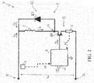
Figure 2 is a schematic view of a power and control unit included in the coil actuator according to the invention; -
Figure 3 is an example of operation of the coil actuator according to the invention. - With reference to the cited figures, the present invention relates to a
coil actuator 1 for low and medium voltage applications. - Conveniently, the
coil actuator 1 is intended to be installed in low or medium voltage apparatuses, such as low or medium voltage circuit breakers, disconnectors, contactors, and the like. - In general, the
coil actuator 1 conveniently comprises a casing (not shown) defining a volume in which the internal components of said coil actuator are accommodated. - According to the invention, the
coil actuator 1 comprises acoil electromagnet 2 provided with a single coil winding 21 and amovable anchor 22. - The
movable anchor 22 is conveniently movable between a rest position and a launch position upon the application of an actuation force. - The
movable anchor 22 is moved from the rest position to the launch position (launch operation) by a magnetic force due to a magnetic flux generated by an excitation current IE flowing along thecoil electromagnet 2, more precisely along thesingle winding 21 of this latter. - Preferably, the
movable anchor 22 is moved from the launch position to the rest position (release operation) by a mechanical force exerted by mechanical means (not shown) included in thecoil electromagnet 2, such as a spring suitably charged during the launch operation of the coil electromagnet. - Preferably, the
movable anchor 22 cannot stably maintain the above-mentioned launch position. To maintain this condition, an excitation current IE has still to flow along the coil electromagnet 2 (hold operation). Once such an excitation current is interrupted or sufficiently reduced, themovable anchor 22 returns in the rest position due to the opposing force exerted by the above-mentioned mechanical means. - Conveniently, when the
coil actuator 1 is installed in a low or medium voltage apparatus, themovable anchor 22 is operatively coupled with a kinematic mechanism of said apparatus. As an example, when thecoil actuator 1 is installed in a medium voltage circuit breaker, themovable anchor 22 may be operatively coupled with the primary command chain of the circuit breaker. - According to the invention, the
coil actuator 1 comprises a power andcontrol unit 3 operatively coupled with thecoil electromagnet 2 to suitably control the operation of this latter. - The power and
control unit 3 comprises a power circuit 4 and aPWM controller 6. - The power circuit 4 is operatively coupled with the
coil electromagnet 2 to drive this latter upon receiving an input voltage VIN at suitable input terminals T1, T2. In this way, when the power circuit is fed with the input voltage VIN, thecoil electromagnet 2 can be fed by a suitable excitation current IE and an operation of thecoil electromagnet 2 can be carried out. Preferably, the input voltage VIN has a DC waveform. - More preferably, the input voltage VIN has a rectified full-wave sinusoidal waveform having a given operating frequency (e.g. 50 Hz).
- However, in principle, the input voltage VIN may have different waveforms, such as a rectified half-wave sinusoidal waveform, a pulsed waveform or a continuous waveform. Preferably, the power and
control unit 3 comprises first sensing means 5 (e.g. a resistive divider) adapted to provide first detection signals S1 indicative of a behavior of the input voltage VIN received by the power circuit 4. - As it will better emerge from the following, an input current IIN may flow through the power circuit 4, when an input voltage VIN is supplied to this latter.
- Preferably, the power and
control unit 3 comprises second sensing means 7 (e.g. a resistive shunt) adapted to provide second detection signals S2 indicative of a behavior of the input voltage IIN received by the power circuit 4. - The
PWM controller 6 is operatively coupled with the power circuit 4 to control the operation of this latter. In particular, as it will be better emerge from the following, thePWM controller 6 is adapted to control the input current IIN flowing through the power circuit 4. - Preferably, the
PWM controller 6 is operatively coupled with the first sensing means 5 in order to receive and process the first detection signals S1, and possibly, with the second sensing means 7 in order to receive and process the second detection signals S2. - The
PWM controller 6 may include one or more computerized units (e.g. microprocessors) configured to execute software instructions to carry out the functionalities provided for said controller. In general, thePWM controller 6 may be may be realized according to solutions of known type and it will be hereinafter described only for the aspects relevant to the invention, for the sake of brevity. - Preferably, the
coil actuator 1 comprises or is operatively connected with a further control unit 8 adapted to interact with the power andcontrol unit 3, for example with thePWM controller 6. - The control unit 8 may include one or more computerized units (e.g. microprocessors) configured to execute software instructions to carry out the functionalities provided for said control unit. In general, the control unit 8 may be realized according to solutions of known type and it will be hereinafter described only for the aspects relevant to the invention, for the sake of brevity.
- Preferably, the
coil actuator 1 comprises apower supply unit 9 operatively coupled with the power andcontrol unit 3 and, possibly, with the control unit 8, to feed these latter units. - In particular, the
power supply unit 9 is adapted to provide the input voltage VIN received by the power circuit 4 of the power andcontrol unit 3. - Preferably, the
power supply stage 9 comprises a power supply circuit (not shown) adapted to receive a power supply voltage from a power supply source (e.g. an electric line). - Preferably, the
power supply stage 9 comprises a filter circuit (e.g. a LC filter - not shown) that may be configured to cut high frequency current components (possibly generated by the PWM controller 6) or other disturbances coming from the power supply source. - Preferably, the
power supply stage 9 comprises a rectifier circuit (e.g. a circuit bridge - not shown) to convert the power supply voltage (e.g. a sinusoidal voltage) provided by the above-mentioned power supply circuit into a suitable input voltage VIN (e.g. a rectified sinusoidal voltage) to be received by the by the power circuit 4 of the power andcontrol unit 3. - The
power supply stage 9 may further comprise additional power supply circuitry (not shown) to feed specific components of the coil actuator (e.g. thePWM controller 6 and the control unit 8) with suitable power supply voltages. - The operation of the
power supply stage 9 may be controlled by the further control unit 8, at least for what concerning the feeding of the power andcontrol unit 3. - In general, the
power supply stage 9 may be realized according to solutions of known type and it will be hereinafter described only for the aspects relevant to the invention, for the sake of brevity. - As mentioned above, the power circuit 4 comprises a first input terminal T1 and a second input terminal T2, at which it receives the input voltage VIN and, possibly, the input current IIN from the
power supply unit 9. - Preferably, the power circuit 4 comprises a
switch circuit 41 and adischarge circuit 42. Preferably, the power circuit 4 comprises an intermediate electric node T3 at which theelectromagnet 2, theswitch circuit 41 and thedischarge circuit 42 are electrically connected. Preferably, thedischarge circuit 42 is electrically connected in parallel with the electromagnet 2 (more precisely with the winding 21 of this latter) between the first input terminal T1 and the electric node T3. - Conveniently, the
discharge circuit 42 is designed to allow the equivalent inductance formed by theelectromagnet 2 to discharge when this latter is not fed by the input current IIN. - To this aim, the
discharge circuit 42 comprises a free-wheeling device suitably arranged to allow the circulation of a discharge current ID when the equivalent inductance formed by theelectromagnet 2 is subject to discharge. - Preferably, said free-wheeling device comprises a free-wheeling diode 420 (which may be of conventional type) having its anode and cathode electrically connected respectively with the electric node T3 and the first input terminal T1.
- Preferably, the
switch circuit 41 is electrically connected in series with the parallel group formed by thedischarge circuit 42 and thecoil electromagnet 2. - More precisely, the
switch circuit 41 is electrically connected between the electric node T3 and the second input terminal T2. - Conveniently, the
switch circuit 41 is designed to allow/prevent the input current IIN (which is received by the power circuit 4 when the input voltage VIN is applied at its input terminals T1, T2) to feed thecoil electromagnet 2. To this aim, theswitch circuit 41 comprises atleast power switch 410. - Preferably, said at least a power switch comprises a
power switch 410, which may be of conventional type, for example a power MOSFET or BJT. - Preferably, the
power switch 410 has its drain or collector terminal and its source or emitter terminal electrically connected respectively with the electric node T3 and the second input terminal T2. - The
power switch 410 is conveniently adapted to switch with a given switch frequency between a conduction state and an interdiction state. - The above-mentioned switch frequency is normally very higher than the operating frequency of the electric quantities characterizing the power circuit 4. As an example, the switching frequency of said power switch may of 10 kHz whereas the input voltage VIN may have an operating frequency of some tens of Hz.
- When the
power switch 410 is in a conduction state, the input current IIN is allowed to flow through the power circuit 4, more precisely along theelectromagnet 2 passing through said power switch and the input terminals T1, T2. In this case, the equivalent inductance formed by theelectromagnet 2 is charged. Additionally, the free-wheeling diode 420 is in an interdiction state and no currents will flow through it (with the exception of small leakage currents). - When the
power switch 410 is in an interdiction state, the input current IIN is interrupted. Thus, no currents will pass through it (with the exception of small leakage currents) and the input terminals T1, T2. In this case, the free-wheeling diode 420 is in a conduction state and a discharge current ID will flow through thedischarge circuit 42, thereby causing the discharge of the equivalent inductance formed by theelectromagnet 2. - Preferably, the
PWM controller 6 is operatively coupled with theswitch circuit 41 to control the operation of the above-mentioned atleast power switch 410. - Preferably, the
PWM controller 6 is adapted to control thepower switch 410. To this aim, it conveniently provides control signals VG (e.g. voltage signals of the pulsed type) to the gate or base terminal of such a power switch. - Preferably, the
PWM controller 6 is adapted to control a duty-cycle value D of thepower switch 410. - In this way, according to the well-known principles of PWM-like controls, the
PWM controller 6 is capable of controlling an average value of the input current IIN (in a time interval very longer than the switching period of thepower switch 410, such the period of the input voltage VIN) in such a way to make this latter to follow a given reference value (e.g. the reference value I1 or I2 or I3 as it will better emerge from the following) set for said input current. - In practice, the
PWM controller 6 compares the measured average values of the input current IIN (provided by the second detection signals S2 sent by the second sensing means 7) with the set reference value I1, I2, I3 and varies the duty-cycle value D of thepower switch 410 on the base of an error value obtained from such a comparison. - Obviously, an increase or decrease of the duty-cycle value D of the
power switch 410 will determine a corresponding increase or decrease of the average value of the input current IIN, respectively. - According to some embodiments (as shown in
figure 2 ), theswitch circuit 41 may include the above-mentioned second sensing means 7. In this case, the second sensing means 7 may be formed a resistive shunt electrically connected in series with thepower switch 410 and the input terminal T2 of the power circuit 4. - In order to operate, the electromagnet 2 (more precisely along the winding 21 of this latter) has to be fed with an excitation current IE having an average operating level IL, IH for a corresponding time interval, which may be in the order of hundreds of ms, e.g. equal to some tens of time periods of the input voltage VIN, when this latter is a periodic signal.
- The average operating level to be obtained for the excitation current IE may be a predetermined launch level IL, through which the
coil actuator 1 carries out a launch operation of theelectromagnet 2, or a predetermined hold level LH, through which thecoil actuator 1 carries out a hold operation of theelectromagnet 2. - In principle, however, the average operating level to be obtained for the excitation current IE may be of different type, for example a coil supervision level (not shown) to allow checking the integrity of the winding 21 of the
electromagnet 2, when theanchor 22 is a rest position. According to the invention, thePWM controller 6 is adapted to control the input current IIN flowing through the power circuit 4 in such a way to obtain and maintain an average operating level IL, IH selected for the excitation current IE - An important feature of the present invention consists in that the
PWM controller 6 is adapted to set a plurality of different reference values I1, I2, I3 for the input current IIN to control said input current (through a PWM control) in such a way to obtain the average operating level IL, IH selected for the excitation current IE flowing through theelectromagnet 2. - In other words, the
PWM controller 6 is adapted to set a plurality of different reference values I1, I2, I3 to be followed by the input current IIN whenever an average operating level IL, IH is selected for the excitation current IE flowing through theelectromagnet 2 in order to carry out an operation of theelectromagnet 2. - Conveniently, the
PWM controller 6 is adapted to set a different plurality of reference values I1, I2, I3 for each average operating level IL, IH selected for the excitation current IE. Preferably, as it will better emerge from the following, thePWM controller 6 is adapted to set a different triad of reference values I1, I2, I3 for each average operating level IL, IH selected for the excitation current IE. - A further important feature of the present invention consists in the
PWM controller 6 is adapted to select from time to time (i.e. instant by instant) each reference value I1, I2, I3 to be set for the input current IIN depending on the behavior of the input voltage VIN, more particularly depending on the instantaneous value VIN(t) taken said input voltage (conveniently as detected by the first sensing means 5). - The provision of a plurality of different reference values I1, I2, I3 to be set for the input current IIN is particularly useful when the input voltage VIN is intrinsically variable, for example since it has rectified sinusoidal waveform or a pulsed waveform, or it is somehow subject to variations.
- Preferably, when the input voltage VIN is subject to an increase (e.g. during a suitable half-period of a rectified sinusoidal waveform), the
PWM controller 6 is adapted to select: - a first reference value I1 to be set for the input current IIN until the input voltage VIN is lower than a first threshold value VTH1;
- a second reference value I2 to be set for the input current IIN if the input voltage VIN increases above the first threshold value VTH1. The second reference value I2 higher than the first reference value I1;
- a third reference value I3 to be set for the input current IIN if the input voltage VIN increases above a second threshold value VTH2 higher than the first threshold value VTH1. The third reference value I3 is higher than the second reference value I2.
- Preferably, when the input voltage VIN is subject to a decrease (e.g. during another suitable half-period of a rectified sinusoidal waveform), the
PWM controller 6 is adapted to select: - the third reference value I3 to be set for the input current IIN until the input voltage VIN is higher than the first threshold value VTH1;
- the second reference value I2 to be set for the input current IIN if the input voltage VIN decreases under the first threshold value VTH1;
- the first reference value I1 to be set for the input current IIN if the input voltage VIN decreases under a third threshold value VTH3 lower than the first threshold value VTH1.
- The above-mentioned threshold values VTH1, VTH2, VTH3 may be predetermined or selected from time to time (i.e. instant by instant) depending on the selected reference values I1, I2 or I3 to be set for the input current IIN. In this last case, when it selects a plurality of reference values I1, I2 or I3, the PWM selects also a corresponding plurality of threshold values VTH1, VTH2, VTH3 to be checked for setting said reference values.
- Conveniently, the reference values I1, I2, I3 and the threshold values VTH1, VTH2, VTH3 are stored by the
PWM controller 6 in a suitable memory. - The setting of multiple reference values I1, I2, I3 to be followed by the input current IIN depending on the behavior of the input voltage VIN allows obtaining a better control of the average value of the excitation current IE and therefore it remarkably facilitates the obtaining of an average operating level IL, IH selected for the excitation current IE.
- In addition, the setting of multiple reference values I1, I2, I3 for the input current IIN allows avoiding the usage of electrolytic capacitors to store the electric energy necessary to properly drive the
electromagnet 2 when the input voltage VIN varies. - In fact, the multiple reference values I1, I2, I3 may be designed in such a way that the
electromagnet 2 is subject to an extra-charge when the duty-cycle of thepower switch 410 increases due to an increase of the input voltage VIN. - In this way, it is prevented an excessive discharge of the
electromagnet 2 when the duty-cycle of thepower switch 410 is decreased due to a decrease of the input voltage VIN. - Preferably, the
PWM controller 6 is adapted to select the average operating level IL, IH to be obtained for the excitation current IE and a corresponding plurality of reference values I1, I2, I3 to be set for the input current IIN depending on the behavior of the input voltage VIN, more specifically depending on one or more characteristic parameters (e.g. the peak value, the RMS value or the like) detected for the input voltage VIN. - Conveniently, the
PWM controller 6 continuously checks one or more characteristic parameters of the input voltage VIN through the first sensing means 5. - Basing on such a checking, the
PWM controller 6 acquires information on the operating status of thecoil actuator 1 and, accordingly, it selects the average operating level IL, IH to be obtained for the excitation current IE and the corresponding plurality of reference values I1, I2, I3 according to which the input current IIN is controlled, - As an example, when the RMS value of the voltage VIN exceeds a given threshold, the
PWM controller 6 detects that an incoming launch operation of theelectromagnet 2 has to be carried out and it selects a predetermined launch level IL to be obtained for the excitation current IE and a corresponding plurality of reference values I1, I2, I3 to be followed by the excitation current IE in such a way that said predetermined launch level IL for the excitation current IE is obtained and the desired launch operation is carried out. - Conveniently, said one or more characteristic parameters of the input voltage VIN may be varied by the
power supply unit 9 upon receiving suitable control signals sent by the additional control unit 8. - In combination with or alternatively to the above solution, the
PWM controller 6 may select the average operating level IL, IH to be obtained for the excitation current IE and the corresponding plurality of reference values I1, I2, I3 for the input current IIN in response to control signals COM received at a suitable communication port 61 (e.g. a CAN-bus communication port). The control signals COM may be transmitted by the additional control unit 8 of thecoil actuator 1 to suitably mange the operation of this latter. - Referring to
figures 2-3 , an example of operation of the power andcontrol unit 3 is now described in further details. - In this example, the power circuit 4 is supposed to receive an input voltage VIN having a rectified full-wave sinusoidal waveform (e.g. with a period of 10 ms), as shown in
figure 3 . Additionally, theelectromagnet 2 is supposed have already carried out some charge/discharge cycles. - The
PWM controller 6 is supposed to select an average operating level IH (hold level) to be obtained for the excitation current IE for a given time interval (e.g. 100 ms - equal to 10 periods of the input voltage VIN) to carry out a hold operation of theelectromagnet 2 Accordingly, thePWM controller 6 selects a triad of stored reference values I1, I2, I3 (and possibly a corresponding triad of threshold values for the input voltage VTH1, VTH2, VTH3) to be used for carrying out a PWM control of the input current IIN and obtaining the selected launch level IL for the excitation current IE. - In order to select the most suitable reference value I1, I2 or I3 to be set for the input current IIN, the PWM checks the behavior of the input voltage VIN basing on the first detection signals provided by the first sensing means 5.
- In a first half-period, the input voltage VIN is subject to an increase.
- Initially, the input voltage VIN is lower than the first threshold value VTH1. The
PWM controller 6 thus selects the first reference value I1 for the input current IIN. In order to force the input current IIN to follow the reference value I1, thePWM controller 6 provides control signals VG to thepower switch 410 to operate this latter with a first duty-cycle value D1 that is relatively low. The input current IIN will follow the first reference value I1. As first duty-cycle value has been previously decreased, the excitation current IE decreases towards a certain steady-state value (not shown) that depends on the reference value I1 set for the input current IIN and the first duty-cycle value D1 set for thepower switch 410. - At the instant t1, the input voltage VIN exceeds the first threshold value VTH1. The
PWM controller 6 thus selects the second reference value I2 to be set for the input current IIN. The second reference value I2 is higher than the first reference value I1. ThePWM controller 6 provides control signals VG to thepower switch 410 to operate this latter with a second duty-cycle value D2 that is higher than the first duty-cycle value D1. The input current IIN will increase to follow the second reference value I2. As the duty-cycle value for thepower switch 410 is now higher, the excitation current IE stops decreasing (in this case without reaching the above-mentioned steady state value) and starts increasing to reach a new higher steady state value IE1. The new steady state value IE1 depends on the reference value I2 set for the input current IIN and the second duty-cycle value D2 set for thepower switch 410. In practice, the new steady state value IE1 is given by the following relation IE1 = IIN*D2. The excitation current IE will remain constant at the steady state value IE1 until the duty-cycle of thepower switch 410 changes again. - At the instant t2, the input voltage VIN exceeds the second threshold value VTH2. The
PWM controller 6 thus selects the third reference value I3 to be set for the input current IIN. The third reference value I3 is higher than the second reference value I2. ThePWM controller 6 provides control signals VG to thepower switch 410 to operate this latter with a third duty-cycle value D3 that is higher than the second duty-cycle value D2. The input current IIN will again increase to follow the third reference value I3. As the duty-cycle value set for thepower switch 410 is still higher, the excitation current IE continues to increase until it reaches a still higher new steady state value IE2. The steady state value IE2 depends on the reference value I3 set for the input current IIN and the second duty-cycle value D3 set for thepower switch 410. In practice, the steady state value IE2 is given by the following relation IE2 = IIN*D3. The excitation current IE will remain constant at the steady state value IE2 until the duty-cycle of thepower switch 410 changes again. It is observed that theelectromagnet 2 is subject to an extra-charge when excitation current IE is at the steady state value IE2 with respect to a steady-state condition with the excitation current IE is at the steady state value IE1, which, in principle, would be closer to the selected average operating level IH. As it will apparent in the following, however, such an extra-charge of theelectromagnet 2 is useful to prevent an excessive discharge of this latter when the input voltage VIN decreases. - In a second half-period, the input voltage VIN is subject to a decrease.
- Initially, the input voltage VIN remains higher than the first threshold value VTH1. The
PWM controller 6 thus maintains the third reference value I3 for the input current IIN. The input current IIN will continue to follow the third reference value I3 and the excitation current IE continues to maintain the steady state value IE2. - At the instant t3, the input voltage VIN decreases below the first threshold value VTH1. The
PWM controller 6 thus selects the second reference value I2 to bet set for the input current IIN. ThePWM controller 6 provides control signals VG to thepower switch 410 to operate this latter with the corresponding second duty-cycle value D2. The input current IIN decreases to follow the second reference value I2. As the duty-cycle value set for thepower switch 410 is now lower, the excitation current IE starts decreasing towards the lower steady state value IE1. At the instant t4, the input voltage VIN decreases below the third threshold value VTH3. ThePWM controller 6 thus selects the first reference value I1 to be set for the input current IIN. ThePWM controller 6 provides control signals VG to thepower switch 410 to operate this latter with the corresponding first duty-cycle value D1. The input current IIN decreases to follow the first reference value I1. As the duty-cycle value set for thepower switch 410 is still lower, the excitation current IE continues decreasing (in this case without stopping at the steady state value IE1) towards a still lower new steady state value. The excitation current IE will continue to decrease until the duty-cycle of thepower switch 410 changes again. As mentioned above, such a change of the duty-cycle of thepower switch 410 will conveniently occur before the excitation current IE reaches the new lower steady state value since theelectromagnet 2 has a prolonged discharge time due to the undergone extra-charge when excitation current IE was at the steady state value IE2. In this way, an excessive discharge of theelectromagnet 2 is prevented. - At the following periods of the input voltage VIN, the above described operation of the power and
control unit 3 is repeated. The excitation current IE thus varies about the selected average operating level IH without the contribution of stored energy to be provided by electrolytic capacitors. - The above described operation of the power and
control unit 3 will be conveniently repeated until thePWM controller 6 selects another average operating level (e.g. the launch level IL) to be obtained for the excitation current IE. - In this last case, the
PWM controller 6 will control the input current IIN in such a way to make the excitation current IE to vary about the selected launch level IL by suitably selecting the reference values I1, I2, I3 at each period of the input voltage VIN. - The
coil actuator 1, according to the invention, allows achieving the intended aims and objects. - The
coil actuator 1 is provided with a power andcontrol unit 3 having a compact design and capable of properly driving theelectromagnet 2 without the employment of electrolytic capacitors. Higher levels of reliability and a longer operating life with respect to solutions used in currently available coil actuators are ensured. - The
coil actuator 1 can be easily manufactured at industrial level at competitive costs with respect to currently available devices of the same type.
Claims (12)
- A coil actuator (1) for low and medium voltage applications comprising:- a coil electromagnet (2) provided with a single coil winding (21) and a movable anchor (22);- a power and control unit (3) comprising:characterised in that said PWM controller (6) is adapted to set a plurality of reference values (I1, I2, I3) for said input current (IIN) to control said input current (IIN) and obtain the average operating level (IL, IH) selected for said excitation current (IE), each reference value (I1, I2, I3) to be set for said input current (IIN) being selected among said plurality of reference values depending on the behavior of said input voltage (VIN).- a power circuit (4) operatively coupled with said coil electromagnet (2), said power circuit comprising input terminals (T1, T2), at which said power circuit receives an input voltage (VIN);- a PWM controller (6) operatively coupled with said power circuit (4), said PWM controller being adapted to control an input current (IIN) flowing through said power circuit (4) to obtain an average operating level (IL, IH) selected for an excitation current (IE) feeding said coil electromagnet;
- Coil actuator, according to claim 1, characterised in that, when said input voltage (VIN) is subject to an increase, said PWM controller (6) is adapted to select:- a first reference value (I1) to be set for said input current (IIN) until said input voltage (VIN) is lower than a first threshold value (VTH1);- a second reference value (I2) to be set for said input current (IIN) if said input voltage (VIN) increases above said first threshold value (VTH1), said second reference value (I2) being higher than said first reference value (I1);- a third reference value (I3) to be set for said input current (IIN) if said input voltage (VIN) increases above a second threshold value (VTH2) higher than said first threshold value (VTH1), said third reference value (I3) being higher than said second reference value (I2).
- Coil actuator, according to one or more of the previous claims, characterised in that, when said input voltage (VIN) is subject to a decrease, said PWM controller (6) is adapted to select:- a third reference value (I3) to be set for said input current (IIN) until said input voltage (VIN) is higher than said first threshold value (VTH1);- a second reference value (I2) to be set for said input current (IIN) if said input voltage (VIN) decreases under said first threshold value (VTH1), said third reference value (I3) being higher than said second reference value (I2);- a first reference value (I1) to be for said input current (IIN) if said input voltage (VIN) decreases under a third threshold value (VTH3) lower than said first threshold value (VTH1), said second reference value (I2) being higher than said first reference value (I1).
- Coil actuator, according to one or more of the previous claims, characterised in that said power and control unit (3) comprises first sensing means (5) adapted to provide first detection signals (S1) indicative of a behavior of said input voltage (VIN), said PWM controller being adapted to receive and process said first detection signals.
- Coil actuator, according to one or more of the previous claims, characterised in that said power and control unit (3) comprises second sensing means (7) adapted to provide second detection signals (S2) indicative of a behavior of said input current (IIN), said PWM controller being adapted to receive and process said second detection signals.
- Coil actuator, according to one or more of the previous claims, characterised in that said power circuit (4) comprises a discharge circuit (42), which is electrically connected with a first input terminal (T1) and an electric node (T3) of said power circuit (4) in parallel with said coil electromagnet (2), and a switch circuit (41), which is electrically connected with said electric node (T3) and a second input terminal (T2) of said power circuit (4), said switch circuit comprising at least a power switch (410), said PWM controller (6) being operatively coupled with said switch circuit (41) to control operation of said at least a power switch.
- Coil actuator, according to claim 6, characterised in that said at least a power switch comprises a power switch (410) adapted to switch with a given switch frequency between a conduction state, at which said input current (IIN) is allowed to flow through said power circuit (4), and an interdiction state, at which said input current (IIN) is interrupted.
- Coil actuator, according to claim 7, characterised in that a discharge current (ID) flows along said discharge circuit (42), when said power switch (410) is in a conduction state.
- Coil actuator, according to one of the claims from 7 to 8, characterised in that that said PWM controller (6) is adapted to control a duty-cycle value (D) of said power switch (410) in order to make said input current (IIN) to reach a reference value (I1, I2, I3) set for said input current.
- Coil actuator, according to one or more of the previous claims, characterised in that said PWM controller (6) is adapted to select an average operating level (IL, IH) to be obtained for said excitation current (IE) and a corresponding plurality of reference values (I1, I2, I3) to be set for said input current (IIN) depending on one or more characteristic parameters detected for said input voltage (VIN).
- Coil actuator, according to one or more of the previous claims, characterised in that said PWM controller (6) is adapted to select the average operating level (IL, IH) to be obtained for said excitation current (IE) and a corresponding plurality of reference values (I1, I2, I3) to be set for said input current (IIN) in response to control signals (COM) received at a communication port (61).
- A low or medium voltage apparatus, characterised in that it comprises a coil actuator (1), according to one or more of the previous claims.
Priority Applications (3)
| Application Number | Priority Date | Filing Date | Title |
|---|---|---|---|
| EP18192708.8A EP3621090B1 (en) | 2018-09-05 | 2018-09-05 | A coil actuator for low and medium voltage applications |
| CN201910832693.3A CN110880398B (en) | 2018-09-05 | 2019-09-04 | Coil actuator for low and medium voltage applications |
| US16/559,830 US11270825B2 (en) | 2018-09-05 | 2019-09-04 | Coil actuator for low and medium voltage applications |
Applications Claiming Priority (1)
| Application Number | Priority Date | Filing Date | Title |
|---|---|---|---|
| EP18192708.8A EP3621090B1 (en) | 2018-09-05 | 2018-09-05 | A coil actuator for low and medium voltage applications |
Publications (2)
| Publication Number | Publication Date |
|---|---|
| EP3621090A1 true EP3621090A1 (en) | 2020-03-11 |
| EP3621090B1 EP3621090B1 (en) | 2022-11-02 |
Family
ID=63517755
Family Applications (1)
| Application Number | Title | Priority Date | Filing Date |
|---|---|---|---|
| EP18192708.8A Active EP3621090B1 (en) | 2018-09-05 | 2018-09-05 | A coil actuator for low and medium voltage applications |
Country Status (3)
| Country | Link |
|---|---|
| US (1) | US11270825B2 (en) |
| EP (1) | EP3621090B1 (en) |
| CN (1) | CN110880398B (en) |
Families Citing this family (1)
| Publication number | Priority date | Publication date | Assignee | Title |
|---|---|---|---|---|
| DE102024203959B3 (en) * | 2024-04-26 | 2025-07-10 | Siemens Aktiengesellschaft | Method for determining electrical resistance |
Citations (4)
| Publication number | Priority date | Publication date | Assignee | Title |
|---|---|---|---|---|
| US20090015980A1 (en) * | 2007-07-09 | 2009-01-15 | Smc Kabushiki Kaisha | Solenoid valve driving circuit and solenoid valve |
| US20090015979A1 (en) * | 2007-07-09 | 2009-01-15 | Smc Kabushiki Kaisha | Solenoid valve driving circuit and solenoid valve |
| EP2149890B1 (en) | 2008-07-31 | 2014-12-24 | ABB Technology AG | A single coil actuator for low and medium voltage applications. |
| US20180174786A1 (en) * | 2016-03-16 | 2018-06-21 | Fuji Electric Fa Components & Systems Co., Ltd. | Operation coil drive device for magnetic contactor |
Family Cites Families (2)
| Publication number | Priority date | Publication date | Assignee | Title |
|---|---|---|---|---|
| ES2786501T3 (en) * | 2012-07-23 | 2020-10-13 | Whirlpool Co | A power supply device for a domestic appliance and a method of operation thereof |
| EP3220406B1 (en) * | 2016-03-14 | 2018-10-03 | ABB S.p.A. | A coil actuator for lv or mv applications |
-
2018
- 2018-09-05 EP EP18192708.8A patent/EP3621090B1/en active Active
-
2019
- 2019-09-04 US US16/559,830 patent/US11270825B2/en active Active
- 2019-09-04 CN CN201910832693.3A patent/CN110880398B/en active Active
Patent Citations (4)
| Publication number | Priority date | Publication date | Assignee | Title |
|---|---|---|---|---|
| US20090015980A1 (en) * | 2007-07-09 | 2009-01-15 | Smc Kabushiki Kaisha | Solenoid valve driving circuit and solenoid valve |
| US20090015979A1 (en) * | 2007-07-09 | 2009-01-15 | Smc Kabushiki Kaisha | Solenoid valve driving circuit and solenoid valve |
| EP2149890B1 (en) | 2008-07-31 | 2014-12-24 | ABB Technology AG | A single coil actuator for low and medium voltage applications. |
| US20180174786A1 (en) * | 2016-03-16 | 2018-06-21 | Fuji Electric Fa Components & Systems Co., Ltd. | Operation coil drive device for magnetic contactor |
Also Published As
| Publication number | Publication date |
|---|---|
| US20200075212A1 (en) | 2020-03-05 |
| US11270825B2 (en) | 2022-03-08 |
| EP3621090B1 (en) | 2022-11-02 |
| CN110880398A (en) | 2020-03-13 |
| CN110880398B (en) | 2021-08-03 |
Similar Documents
| Publication | Publication Date | Title |
|---|---|---|
| US5671115A (en) | Circuit arrangement for driving a contactor | |
| US10250031B2 (en) | Magnetic coil driving circuit for magnetic contactor | |
| US10755881B2 (en) | Circuit arrangement for operating electromagnetic drive systems | |
| JP7252412B2 (en) | coil drive | |
| US10825627B2 (en) | Controllable electric current switchgear and electrical assembly comprising this switchgear | |
| CN108141910A (en) | Household appliance | |
| US7369391B2 (en) | Drive circuit of direct-current voltage-driven magnetic contactor and power converter | |
| US11289256B2 (en) | Coil actuator for low and medium voltage applications | |
| US20180199407A1 (en) | Dimming device | |
| US11270825B2 (en) | Coil actuator for low and medium voltage applications | |
| EP4404463B1 (en) | Static ac switch with extended current range | |
| US10176951B2 (en) | Constant voltage supplying circuit for circuit breaker | |
| US4687985A (en) | Two terminal control switch having a main switch and a saturable current transformer whose primary winding is series connected with the main switch | |
| KR20000057100A (en) | Power supply for electronic instrument | |
| EP4571807A1 (en) | Supervisor unit for low and medium voltage applications | |
| JP2013109641A (en) | Two-wire system load control device | |
| US20210313131A1 (en) | Relay module | |
| US20220376553A1 (en) | Power receiving device and wireless power transfer system | |
| US12300452B2 (en) | Solenoid driver for a circuit breaker | |
| US12555730B2 (en) | Relay module with combined control and power supply input | |
| JPH06141548A (en) | Inrush current suppression circuit | |
| JP2025018116A (en) | Switching Power Supply | |
| SU1035568A1 (en) | Electromagnetic relay checking device | |
| US10574083B2 (en) | Electronic charger for electric power distribution installations and a control method thereof | |
| CN121617856A (en) | Contactor and electrical equipment |
Legal Events
| Date | Code | Title | Description |
|---|---|---|---|
| PUAI | Public reference made under article 153(3) epc to a published international application that has entered the european phase |
Free format text: ORIGINAL CODE: 0009012 |
|
| STAA | Information on the status of an ep patent application or granted ep patent |
Free format text: STATUS: THE APPLICATION HAS BEEN PUBLISHED |
|
| AK | Designated contracting states |
Kind code of ref document: A1 Designated state(s): AL AT BE BG CH CY CZ DE DK EE ES FI FR GB GR HR HU IE IS IT LI LT LU LV MC MK MT NL NO PL PT RO RS SE SI SK SM TR |
|
| AX | Request for extension of the european patent |
Extension state: BA ME |
|
| STAA | Information on the status of an ep patent application or granted ep patent |
Free format text: STATUS: REQUEST FOR EXAMINATION WAS MADE |
|
| 17P | Request for examination filed |
Effective date: 20200720 |
|
| RBV | Designated contracting states (corrected) |
Designated state(s): AL AT BE BG CH CY CZ DE DK EE ES FI FR GB GR HR HU IE IS IT LI LT LU LV MC MK MT NL NO PL PT RO RS SE SI SK SM TR |
|
| STAA | Information on the status of an ep patent application or granted ep patent |
Free format text: STATUS: EXAMINATION IS IN PROGRESS |
|
| 17Q | First examination report despatched |
Effective date: 20211012 |
|
| GRAP | Despatch of communication of intention to grant a patent |
Free format text: ORIGINAL CODE: EPIDOSNIGR1 |
|
| STAA | Information on the status of an ep patent application or granted ep patent |
Free format text: STATUS: GRANT OF PATENT IS INTENDED |
|
| INTG | Intention to grant announced |
Effective date: 20220520 |
|
| GRAS | Grant fee paid |
Free format text: ORIGINAL CODE: EPIDOSNIGR3 |
|
| GRAA | (expected) grant |
Free format text: ORIGINAL CODE: 0009210 |
|
| STAA | Information on the status of an ep patent application or granted ep patent |
Free format text: STATUS: THE PATENT HAS BEEN GRANTED |
|
| AK | Designated contracting states |
Kind code of ref document: B1 Designated state(s): AL AT BE BG CH CY CZ DE DK EE ES FI FR GB GR HR HU IE IS IT LI LT LU LV MC MK MT NL NO PL PT RO RS SE SI SK SM TR |
|
| REG | Reference to a national code |
Ref country code: GB Ref legal event code: FG4D |
|
| REG | Reference to a national code |
Ref country code: CH Ref legal event code: EP Ref country code: AT Ref legal event code: REF Ref document number: 1529378 Country of ref document: AT Kind code of ref document: T Effective date: 20221115 |
|
| REG | Reference to a national code |
Ref country code: DE Ref legal event code: R096 Ref document number: 602018042485 Country of ref document: DE |
|
| REG | Reference to a national code |
Ref country code: IE Ref legal event code: FG4D |
|
| REG | Reference to a national code |
Ref country code: LT Ref legal event code: MG9D |
|
| REG | Reference to a national code |
Ref country code: NL Ref legal event code: MP Effective date: 20221102 |
|
| REG | Reference to a national code |
Ref country code: AT Ref legal event code: MK05 Ref document number: 1529378 Country of ref document: AT Kind code of ref document: T Effective date: 20221102 |
|
| PG25 | Lapsed in a contracting state [announced via postgrant information from national office to epo] |
Ref country code: SE Free format text: LAPSE BECAUSE OF FAILURE TO SUBMIT A TRANSLATION OF THE DESCRIPTION OR TO PAY THE FEE WITHIN THE PRESCRIBED TIME-LIMIT Effective date: 20221102 Ref country code: PT Free format text: LAPSE BECAUSE OF FAILURE TO SUBMIT A TRANSLATION OF THE DESCRIPTION OR TO PAY THE FEE WITHIN THE PRESCRIBED TIME-LIMIT Effective date: 20230302 Ref country code: NO Free format text: LAPSE BECAUSE OF FAILURE TO SUBMIT A TRANSLATION OF THE DESCRIPTION OR TO PAY THE FEE WITHIN THE PRESCRIBED TIME-LIMIT Effective date: 20230202 Ref country code: LT Free format text: LAPSE BECAUSE OF FAILURE TO SUBMIT A TRANSLATION OF THE DESCRIPTION OR TO PAY THE FEE WITHIN THE PRESCRIBED TIME-LIMIT Effective date: 20221102 Ref country code: FI Free format text: LAPSE BECAUSE OF FAILURE TO SUBMIT A TRANSLATION OF THE DESCRIPTION OR TO PAY THE FEE WITHIN THE PRESCRIBED TIME-LIMIT Effective date: 20221102 Ref country code: ES Free format text: LAPSE BECAUSE OF FAILURE TO SUBMIT A TRANSLATION OF THE DESCRIPTION OR TO PAY THE FEE WITHIN THE PRESCRIBED TIME-LIMIT Effective date: 20221102 Ref country code: AT Free format text: LAPSE BECAUSE OF FAILURE TO SUBMIT A TRANSLATION OF THE DESCRIPTION OR TO PAY THE FEE WITHIN THE PRESCRIBED TIME-LIMIT Effective date: 20221102 |
|
| PG25 | Lapsed in a contracting state [announced via postgrant information from national office to epo] |
Ref country code: RS Free format text: LAPSE BECAUSE OF FAILURE TO SUBMIT A TRANSLATION OF THE DESCRIPTION OR TO PAY THE FEE WITHIN THE PRESCRIBED TIME-LIMIT Effective date: 20221102 Ref country code: PL Free format text: LAPSE BECAUSE OF FAILURE TO SUBMIT A TRANSLATION OF THE DESCRIPTION OR TO PAY THE FEE WITHIN THE PRESCRIBED TIME-LIMIT Effective date: 20221102 Ref country code: LV Free format text: LAPSE BECAUSE OF FAILURE TO SUBMIT A TRANSLATION OF THE DESCRIPTION OR TO PAY THE FEE WITHIN THE PRESCRIBED TIME-LIMIT Effective date: 20221102 Ref country code: IS Free format text: LAPSE BECAUSE OF FAILURE TO SUBMIT A TRANSLATION OF THE DESCRIPTION OR TO PAY THE FEE WITHIN THE PRESCRIBED TIME-LIMIT Effective date: 20230302 Ref country code: HR Free format text: LAPSE BECAUSE OF FAILURE TO SUBMIT A TRANSLATION OF THE DESCRIPTION OR TO PAY THE FEE WITHIN THE PRESCRIBED TIME-LIMIT Effective date: 20221102 Ref country code: GR Free format text: LAPSE BECAUSE OF FAILURE TO SUBMIT A TRANSLATION OF THE DESCRIPTION OR TO PAY THE FEE WITHIN THE PRESCRIBED TIME-LIMIT Effective date: 20230203 |
|
| PG25 | Lapsed in a contracting state [announced via postgrant information from national office to epo] |
Ref country code: NL Free format text: LAPSE BECAUSE OF FAILURE TO SUBMIT A TRANSLATION OF THE DESCRIPTION OR TO PAY THE FEE WITHIN THE PRESCRIBED TIME-LIMIT Effective date: 20221102 |
|
| PG25 | Lapsed in a contracting state [announced via postgrant information from national office to epo] |
Ref country code: SM Free format text: LAPSE BECAUSE OF FAILURE TO SUBMIT A TRANSLATION OF THE DESCRIPTION OR TO PAY THE FEE WITHIN THE PRESCRIBED TIME-LIMIT Effective date: 20221102 Ref country code: RO Free format text: LAPSE BECAUSE OF FAILURE TO SUBMIT A TRANSLATION OF THE DESCRIPTION OR TO PAY THE FEE WITHIN THE PRESCRIBED TIME-LIMIT Effective date: 20221102 Ref country code: EE Free format text: LAPSE BECAUSE OF FAILURE TO SUBMIT A TRANSLATION OF THE DESCRIPTION OR TO PAY THE FEE WITHIN THE PRESCRIBED TIME-LIMIT Effective date: 20221102 Ref country code: DK Free format text: LAPSE BECAUSE OF FAILURE TO SUBMIT A TRANSLATION OF THE DESCRIPTION OR TO PAY THE FEE WITHIN THE PRESCRIBED TIME-LIMIT Effective date: 20221102 Ref country code: CZ Free format text: LAPSE BECAUSE OF FAILURE TO SUBMIT A TRANSLATION OF THE DESCRIPTION OR TO PAY THE FEE WITHIN THE PRESCRIBED TIME-LIMIT Effective date: 20221102 |
|
| REG | Reference to a national code |
Ref country code: DE Ref legal event code: R097 Ref document number: 602018042485 Country of ref document: DE |
|
| PG25 | Lapsed in a contracting state [announced via postgrant information from national office to epo] |
Ref country code: SK Free format text: LAPSE BECAUSE OF FAILURE TO SUBMIT A TRANSLATION OF THE DESCRIPTION OR TO PAY THE FEE WITHIN THE PRESCRIBED TIME-LIMIT Effective date: 20221102 Ref country code: AL Free format text: LAPSE BECAUSE OF FAILURE TO SUBMIT A TRANSLATION OF THE DESCRIPTION OR TO PAY THE FEE WITHIN THE PRESCRIBED TIME-LIMIT Effective date: 20221102 |
|
| PLBE | No opposition filed within time limit |
Free format text: ORIGINAL CODE: 0009261 |
|
| STAA | Information on the status of an ep patent application or granted ep patent |
Free format text: STATUS: NO OPPOSITION FILED WITHIN TIME LIMIT |
|
| 26N | No opposition filed |
Effective date: 20230803 |
|
| PG25 | Lapsed in a contracting state [announced via postgrant information from national office to epo] |
Ref country code: SI Free format text: LAPSE BECAUSE OF FAILURE TO SUBMIT A TRANSLATION OF THE DESCRIPTION OR TO PAY THE FEE WITHIN THE PRESCRIBED TIME-LIMIT Effective date: 20221102 |
|
| REG | Reference to a national code |
Ref country code: CH Ref legal event code: PL |
|
| PG25 | Lapsed in a contracting state [announced via postgrant information from national office to epo] |
Ref country code: LU Free format text: LAPSE BECAUSE OF NON-PAYMENT OF DUE FEES Effective date: 20230905 |
|
| REG | Reference to a national code |
Ref country code: BE Ref legal event code: MM Effective date: 20230930 |
|
| GBPC | Gb: european patent ceased through non-payment of renewal fee |
Effective date: 20230905 |
|
| PG25 | Lapsed in a contracting state [announced via postgrant information from national office to epo] |
Ref country code: LU Free format text: LAPSE BECAUSE OF NON-PAYMENT OF DUE FEES Effective date: 20230905 Ref country code: MC Free format text: LAPSE BECAUSE OF FAILURE TO SUBMIT A TRANSLATION OF THE DESCRIPTION OR TO PAY THE FEE WITHIN THE PRESCRIBED TIME-LIMIT Effective date: 20221102 |
|
| REG | Reference to a national code |
Ref country code: IE Ref legal event code: MM4A |
|
| PG25 | Lapsed in a contracting state [announced via postgrant information from national office to epo] |
Ref country code: IE Free format text: LAPSE BECAUSE OF NON-PAYMENT OF DUE FEES Effective date: 20230905 |
|
| PG25 | Lapsed in a contracting state [announced via postgrant information from national office to epo] |
Ref country code: GB Free format text: LAPSE BECAUSE OF NON-PAYMENT OF DUE FEES Effective date: 20230905 |
|
| PG25 | Lapsed in a contracting state [announced via postgrant information from national office to epo] |
Ref country code: CH Free format text: LAPSE BECAUSE OF NON-PAYMENT OF DUE FEES Effective date: 20230930 |
|
| PG25 | Lapsed in a contracting state [announced via postgrant information from national office to epo] |
Ref country code: IE Free format text: LAPSE BECAUSE OF NON-PAYMENT OF DUE FEES Effective date: 20230905 Ref country code: GB Free format text: LAPSE BECAUSE OF NON-PAYMENT OF DUE FEES Effective date: 20230905 Ref country code: CH Free format text: LAPSE BECAUSE OF NON-PAYMENT OF DUE FEES Effective date: 20230930 |
|
| PG25 | Lapsed in a contracting state [announced via postgrant information from national office to epo] |
Ref country code: BE Free format text: LAPSE BECAUSE OF NON-PAYMENT OF DUE FEES Effective date: 20230930 |
|
| PG25 | Lapsed in a contracting state [announced via postgrant information from national office to epo] |
Ref country code: BG Free format text: LAPSE BECAUSE OF FAILURE TO SUBMIT A TRANSLATION OF THE DESCRIPTION OR TO PAY THE FEE WITHIN THE PRESCRIBED TIME-LIMIT Effective date: 20221102 |
|
| PG25 | Lapsed in a contracting state [announced via postgrant information from national office to epo] |
Ref country code: BG Free format text: LAPSE BECAUSE OF FAILURE TO SUBMIT A TRANSLATION OF THE DESCRIPTION OR TO PAY THE FEE WITHIN THE PRESCRIBED TIME-LIMIT Effective date: 20221102 |
|
| PG25 | Lapsed in a contracting state [announced via postgrant information from national office to epo] |
Ref country code: CY Free format text: LAPSE BECAUSE OF FAILURE TO SUBMIT A TRANSLATION OF THE DESCRIPTION OR TO PAY THE FEE WITHIN THE PRESCRIBED TIME-LIMIT; INVALID AB INITIO Effective date: 20180905 |
|
| PG25 | Lapsed in a contracting state [announced via postgrant information from national office to epo] |
Ref country code: HU Free format text: LAPSE BECAUSE OF FAILURE TO SUBMIT A TRANSLATION OF THE DESCRIPTION OR TO PAY THE FEE WITHIN THE PRESCRIBED TIME-LIMIT; INVALID AB INITIO Effective date: 20180905 |
|
| PGFP | Annual fee paid to national office [announced via postgrant information from national office to epo] |
Ref country code: DE Payment date: 20250919 Year of fee payment: 8 |
|
| PGFP | Annual fee paid to national office [announced via postgrant information from national office to epo] |
Ref country code: IT Payment date: 20250923 Year of fee payment: 8 |
|
| PGFP | Annual fee paid to national office [announced via postgrant information from national office to epo] |
Ref country code: FR Payment date: 20250922 Year of fee payment: 8 |
|
| PG25 | Lapsed in a contracting state [announced via postgrant information from national office to epo] |
Ref country code: TR Free format text: LAPSE BECAUSE OF FAILURE TO SUBMIT A TRANSLATION OF THE DESCRIPTION OR TO PAY THE FEE WITHIN THE PRESCRIBED TIME-LIMIT Effective date: 20221102 |