EP3620733A1 - Refrigerator - Google Patents
Refrigerator Download PDFInfo
- Publication number
- EP3620733A1 EP3620733A1 EP19191965.3A EP19191965A EP3620733A1 EP 3620733 A1 EP3620733 A1 EP 3620733A1 EP 19191965 A EP19191965 A EP 19191965A EP 3620733 A1 EP3620733 A1 EP 3620733A1
- Authority
- EP
- European Patent Office
- Prior art keywords
- drawer
- lid
- storage compartment
- refrigerator
- opening
- Prior art date
- Legal status (The legal status is an assumption and is not a legal conclusion. Google has not performed a legal analysis and makes no representation as to the accuracy of the status listed.)
- Granted
Links
Images


Classifications
-
- F—MECHANICAL ENGINEERING; LIGHTING; HEATING; WEAPONS; BLASTING
- F25—REFRIGERATION OR COOLING; COMBINED HEATING AND REFRIGERATION SYSTEMS; HEAT PUMP SYSTEMS; MANUFACTURE OR STORAGE OF ICE; LIQUEFACTION SOLIDIFICATION OF GASES
- F25D—REFRIGERATORS; COLD ROOMS; ICE-BOXES; COOLING OR FREEZING APPARATUS NOT OTHERWISE PROVIDED FOR
- F25D25/00—Charging, supporting, and discharging the articles to be cooled
- F25D25/02—Charging, supporting, and discharging the articles to be cooled by shelves
- F25D25/024—Slidable shelves
- F25D25/025—Drawers
Definitions
- the utility model relates to the field of refrigeration apparatuses, and in particular, to a refrigerator.
- a refrigerator is used as an example.
- one or more drawers are generally disposed in a storage compartment (such as a refrigerating compartment) of the refrigerator.
- a storage compartment such as a refrigerating compartment
- a user may pull out a drawer and take the required stored product. After taking the stored product, the user may push the drawer back into the storage compartment, so that an entire taking process is completed.
- the drawers within the existing refrigerators have open design and poor sealing performance, which easily results in odor tainting of the stored products within the storage compartments and even causes bacteria growth, and consequently, food hygiene is influenced.
- Embodiments of the utility model are intended to provide an improved refrigerator. Therefore, the embodiments of the utility model provide a refrigerator, including: a storage compartment; a drawer located within the storage compartment, the drawer having an opening facing upward; a lid for uncovering or covering the opening, the lid being slidably supported on an upper portion of the drawer, when the drawer is pulled out of the storage compartment, the lid being pulled out with the drawer and keeping the opening covered and sliding relative to the drawer to be pushed back into the storage compartment to uncover the opening; and a block located within the storage compartment, configured to prevent the lid from continuing moving rearward to keep the lid supported on the drawer that is pulled out, and enable the lid to cover the opening when the drawer is pushed into the storage compartment.
- solutions for embodiments of the utility model provide a refrigerator having a drawer.
- the drawer When the drawer is located within a storage compartment of the refrigerator and is pulled out of the storage compartment, an opening of the drawer is covered through a lid supported on the drawer, which can effectively improve sealing performance of the drawer and prevent a stored product in the drawer from being directly exposed within the storage compartment and being tainted with other stored products in the storage compartment, thereby helping improve food hygiene.
- the lid can be pushed by a user to slide forward and rearward relative to the drawer to uncover the opening of the drawer, which is convenient for the user to take the stored product in the drawer.
- the lid can be prevented from excessively moving rearward until detaching from the drawer, so that it can be ensured that the lid is always supported on the drawer while sliding forward and rearward.
- the block is disposed within the storage compartment, when the opening of the drawer is pushed back into the storage compartment in an uncovered state, the user does not need to cover the lid intentionally, but the opening of the drawer can be covered automatically through cooperation of the lid with the block as the drawer is pushed back into the storage compartment, so that the drawer is in a sealed state within the storage compartment.
- the lid includes: a frame, the frame enclosing a viewing port; and a transparent member disposed within the viewing port and connected to the frame. Accordingly, when the drawer is pulled out of the storage compartment, an interior of the drawer can be visually seen without pushing open the lid, and the user can accurately and quickly determine whether a stored product being sought is stored in the drawer, thereby reducing the number of unnecessary uncovering and covering of the drawer. In other words, the user can push open the lid of the drawer to take the stored product after determining that the stored product to be taken is actually stored in the drawer, instead of first uncovering the lid and then determining whether the stored product is in the drawer, which further reduces a possibility of odor tainting.
- the transparent member may be made of tempered glass.
- an area of the viewing port accounts for 60% to 90% of an area of the opening to ensure that all corners inside the drawer can be clearly seen from the viewing port, thereby avoiding a visual blind zone.
- the lid further includes a sealing strip fixed to a lower side of the lid and contacting an upper edge of the drawer when the lid covers the opening, thereby forming a confined space within the drawer, so that sealing performance of the drawer is better.
- the sealing strip may be fixed to a frame disposed surrounding a transparent member.
- the lid is made of a heat-conducting material to conduct temperature through a physical property of the material, thereby achieving a better freezing/unfreezing effect, so that partition storage and short-term sealed refrigeration can be implemented with a simple structural design.
- the drawer has an air duct, a space inside the drawer being in communication with a space outside the drawer when the air duct is opened, and the space inside the drawer being isolated from the space outside the drawer when the air duct is closed. Accordingly, a separate air duct designed on the drawer is beneficial to freely switch between partitioned storage and sealed storage, to meet diversified needs of users.
- the drawer includes a bottom wall, a front wall, a rear wall, a pair of side walls, and a top wall, the top wall being located between the opening and the front wall, and the air duct being located on a top wall of the drawer. Accordingly, when the air duct is opened, air inside the drawer can be quickly exchanged with air outside the drawer, and when the air duct is closed, it can be ensured that the drawer is in a relatively good sealed state. Further, when the drawer is pulled out of the storage compartment, the air duct disposed on the top wall of the drawer enables the user to visually observe a current state of the air duct, so that the user can adjust the air duct to be in an open/closed state as needed.
- the drawer further has a controller connected to the air duct to open or close the air duct. Accordingly, the user can control the air duct to be in an open/closed state as needed to flexibly switch the state of the drawer between the partitioned storage and the sealed storage.
- the lid has a stop, the lid moving rearward relative to the drawer until the stop abuts against the block to prevent the lid from continuing moving rearward. Accordingly, through the cooperation of the block with the stop, when the lid is pushed toward the storage compartment to uncover the opening of the drawer, the lid can be prevented from excessively moving rearward until detaching from the drawer, so that it can be ensured that the lid is always supported on the drawer. Further, when the drawer is pushed back into the storage compartment with the opening uncovered, as the drawer moves rearward, the lid is confined to an original place because the stop abuts against the block thereof. Accordingly, when the drawer moves into the storage compartment, the lid can be naturally covered on the drawer and the opening of the drawer is covered.
- the stop is connected to the handle of the lid, which facilitates overall aesthetic appearance of the drawer while simplifying the structure and being easy to manufacture.
- the block is fixed to an inner wall of the storage compartment and extends to an upper side of the lid to effectively prevent the lid supported on the upper edge of the drawer from excessively moving rearward and control the lid to cover the opening of the drawer when the drawer is pushed backed to the storage compartment.
- the refrigerator further includes: a guide rail, configured to movably fix the drawer within the storage compartment, the drawer being adapted to be pulled out or pushed back into the storage compartment along the guide rail. Accordingly, the user can conveniently pull out or push back the drawer as needed, preventing the drawer and/or the storage compartment from being damaged by unlubricated friction with an inner wall of the storage compartment when the drawer moves forward and rearward relative to the storage compartment, which can help improve user experience.
- an embodiment of the utility model provides a refrigerator, including: a storage compartment; a drawer located within the storage compartment, the drawer having an opening facing upward; a lid for uncovering or covering the opening, the lid being slidably supported at an upper portion of the drawer, when the drawer is pulled out of the storage compartment, the lid being pulled out with the drawer while keeping the opening covered and sliding relative to the drawer to be pushed back into the storage compartment to uncover the opening; and a block located within the storage compartment, configured to prevent the lid from continuing moving rearward to keep the lid supported on the drawer that is pulled out, and enable the lid to cover the opening when the drawer is pushed into the storage compartment.
- the solutions of embodiments of the utility model provide a refrigerator with a drawer.
- the opening of the drawer is covered by a lid supported on the drawer, which can effectively improve sealing performance of the drawer and prevent a stored product in the drawer from being directly exposed within the storage compartment and being tainted with other stored products in the storage compartment, and can help improve food hygiene.
- the lid when the drawer is pulled out of the storage compartment, the lid can be pushed by a user to slide forward and rearward relative to the drawer to uncover the opening of the drawer, which is convenient for the user to take the stored product in the drawer. Further, with the design for the block, the lid can be prevented from excessively moving rearward until detaching from the drawer, so that it can be ensured that the lid is always supported on the drawer while sliding forward and rearward.
- the block is disposed within the storage compartment, when the opening of the drawer is pushed back into the storage compartment in an uncovered state, the user does not need to cover the lid intentionally, but the opening of the drawer can be covered automatically through cooperation of the lid with the block as the drawer is pushed back into the storage compartment, so that the drawer is in a sealed state within the storage compartment.
- FIG. 1 is a partial schematic structural diagram of a refrigerator according to an embodiment of the utility model.
- FIG. 1 mainly takes an example of a storage compartment of the refrigerator and a drawer disposed therein, and further describes a specific structure of the drawer.
- this embodiment may also be applied to a refrigeration apparatus such as a refrigerated cabinet or a freezer in which stored products need to be stored in a separated and sealed manner.
- a refrigeration apparatus such as a refrigerated cabinet or a freezer in which stored products need to be stored in a separated and sealed manner.
- the refrigerator 100 may further include: a storage compartment 110; and a drawer 120 located within the storage compartment 110.
- a size of the drawer 120 may be adapted to an accommodation space of the storage compartment 110.
- the storage compartment 110 may be adapted to accommodate one or more drawers 120.
- the drawer 120 may include a bottom wall 120a, a front wall 120b, a rear wall 120c, and a pair of side walls 120d, and may further include an accommodation space enclosed by the bottom wall 120a, the front wall 120b, the pair of side walls 120d, and the rear wall 120c, and the drawer 120 may have an opening 121 facing upward, the opening 121 exposing the accommodation space.
- the drawer 120 may be adapted to accommodate stored products, and a user may take the stored products placed in the accommodation space from the opening 121. Alternatively, the user may also place the stored products from the opening 121 in the accommodation space.
- a width direction of the refrigerator 100 is set to a direction x
- a depth direction of the refrigerator 100 is set to a direction y
- a height direction of the refrigerator 100 is set to a direction z.
- a direction from inside to outside of the storage compartment 110 is a positive direction of the direction y (that is, the direction +y in the figure).
- a direction in which the drawer 120 is pulled out of the storage compartment 110 is the positive direction of the direction y.
- a plurality of the drawers 120 may be arranged side by side along the direction x, the direction y, and/or the direction z within the storage compartment 110.
- one drawer 120 accommodated within the storage compartment 110 is used as an example for specific description.
- the refrigerator 100 may further include a lid 130 for uncovering or covering the opening 121, the lid 130 being slidably supported on the upper portion of the drawer 120.
- the upper portion of the drawer 120 may refer to an upper edge 122 of at least one of the front wall 120b, a pair of side walls 120d, and a rear wall 120c of the drawer 120.
- a pull-out direction is the direction +y shown in the figure.
- the lid 130 may slide relative to the drawer 120 to be pushed back into the storage compartment 110 to uncover the opening 121.
- a pull-back direction is the direction -y shown in the figure.
- the refrigerator 100 may further include: a block 111 located within the storage compartment 110, configured to prevent the lid 130 from continuing moving rearward to keep the lid 130 supported on the drawer 120 that is pulled out, and when the drawer 120 is pushed into the storage compartment 110, enable the lid 130 to cover the opening 121.
- a block 111 located within the storage compartment 110, configured to prevent the lid 130 from continuing moving rearward to keep the lid 130 supported on the drawer 120 that is pulled out, and when the drawer 120 is pushed into the storage compartment 110, enable the lid 130 to cover the opening 121.
- the block 111 may be fixed to an inner wall of the storage compartment 110 and extend to an upper side of the lid 130, to effectively prevent the lid 130 supported on the upper edge 122 of the drawer 120 from excessively moving rearward, and control the lid 130 to cover the opening 121 of the drawer 120 when the drawer 120 is pushed back into the storage compartment 110.
- the block 111 may be disposed on an inner top wall of the storage compartment 110 and extend downward (that is, along a negative direction of the direction z in the figure) to the upper side of the lid 130.
- the drawer 120 may initially be located within the storage compartment 110, and the lid 130 is supported on the upper edge 122 of the drawer 120 while keeping the opening 121 of the drawer 120 covered.
- the front wall 120b of the drawer 120 may be provided with a handle portion 123, and the user can pull the drawer 120 along the direction +y through the handle portion 123 to pull the drawer 120 out of the storage compartment 110.
- the lid 130 keeps the opening 121 of the drawer 120 covered, as shown in FIG. 4 .
- an upper surface of the lid 130 may be provided with a handle 131, and the user can push the lid 130 along the direction -y through the handle 131 to uncover the opening 121 of the drawer 120, as shown in FIG. 2 .
- the handle 131 extends from the upper surface of the lid 130 toward the direction z. In other words, at an angle shown in FIG. 2 , the handle 131 protrudes from the upper surface of the lid 130.
- the lid 130 slides rearward relative to the drawer 120 at an upper portion of the drawer 120 until the handle 131 abuts against the block 111, to prevent the lid 130 from continuing sliding rearward.
- the user may pull the lid 130 along the direction +y through the handle 131, to manually cover the opening 121 of the drawer 120. Then, the drawer 120 is pushed along the direction -y to push the drawer 120 together with the lid 130 supported thereon back into the storage compartment 110, so that the drawer 120 and the lid 130 return to a state shown in FIG. 5 .
- the user may also push the drawer 120 directly along the direction -y in a state shown in FIG. 2 to push the drawer 120 back into the storage compartment 110.
- the handle 131 of the lid 130 abuts against the block 111, the lid 130 does not move rearward together with the drawer 120 when the drawer 120 moves rearward. Accordingly, through rearward movement of the drawer 120, the lid 130 can gradually cover the opening 121 of the drawer 120 until the drawer 120 and the lid 130 return to the state as shown in FIG. 5 .
- the block 111 may also be disposed on an inner side wall or on a rear wall of the storage compartment 110 and extend to the upper side of the lid 130.
- the upper side of the lid 130 may refer to an upper space of the lid 130 along the direction z.
- the block 111 may extend to an upper surface of the lid 130, and accordingly, the handle 131 only needs to protrude by a small size toward the direction z to abut against the block 111.
- a height of the gap along the direction z may be set to be small enough to prevent a rear end 130b of the lid 130 from rotating downward when the lid 130 is pushed back. Rotating downward refers to rotating along a reverse direction of the direction z.
- the lid 130 may have a stop 132, and the lid 130 moves rearward relative to the drawer 120 until the stop 132 abuts against the block 111, to prevent the lid 130 from continuing moving rearward.
- the lid 130 can be prevented from excessively moving rearward until detaching from the drawer 120, so that it can be ensured that the lid 130 is always supported on the drawer 120.
- the lid 130 is confined to an original place because the stop 132 abuts against the block 111 thereof. Accordingly, when the drawer 120 moves into the storage compartment 110, the lid 130 can be naturally covered on the drawer 120, and the opening 121 of the drawer 120 is covered.
- a height of the stop 132 along the direction z may be greater than a gap between the block 111 and the lid 130, to ensure that the stop 132 abuts against the block 111 when the stop 132 moves to the block 111 along the direction - y relative to the drawer 120 with the lid 130, to prevent the lid 130 from continuing moving rearward.
- the stop 132 may be connected to the handle 131 of the lid 130, which facilitates overall aesthetic appearance of the drawer 120, while simplifying a structure and being easy to manufacture.
- the stop 132 and/or the handle 131 may be fixed to the upper surface of the lid 130 in a manner of bonding, interference fit, or bolting.
- handle 131 and the stop 132 may be integrally formed.
- the stop 132 may be considered as an extension of the handle 131.
- the handle 131 may replace the stop 132 to prevent the lid 130 from sliding rearward, and vice versa.
- a distance that the lid 130 may slide rearward relative to the drawer 120 can be adjusted, and an area in which the opening 121 is uncovered can be further adjusted.
- the handle 131 may be located at a front end 130a of the upper surface of the lid 130, the front end 130a being one end close to a front wall 120b of the drawer 120.
- the block 111 may extend to the upper side of the lid 130 and be close to an outer side (that is, one side close to of the front wall 120b of the drawer 120 when the drawer 120 is located within the storage compartment 110) of the storage compartment 110, to enable the lid 130 to slide rearward to substantially fully uncovering the opening 121 of the drawer 120 when the drawer 120 is pulled out of the storage compartment 110, and prevent the lid 130 from moving until the opening 121 is completely covered when the drawer 120 is pushed back into the storage compartment 110.
- the lid 130 may include: a frame 133, the frame 133 enclosing a viewing port 134; and a transparent member 135, disposed within the viewing port 134 and connected to the frame 133.
- the drawer 120 when the drawer 120 is pulled out of the storage compartment 110, an interior of the drawer 120 can be visually seen without pushing open the lid 130, and the user can accurately and quickly determine whether a stored product being sought is stored within the drawer 120, thereby reducing the number of unnecessary uncovering and covering of the drawer 120.
- the user can push open the lid 130 of the drawer 120 to take the stored product after determining that the stored product to be taken is actually stored in the drawer 120, instead of uncovering the lid 130 first and then determining whether the stored product is in the drawer 120, which further reduces a possibility of odor tainting.
- the transparent member 135 may be made of a glass material to enable the lid 130 to be pressed against the upper edge 122 of the drawer 120 by its own weight while satisfying transparency of the viewing opening 134, thereby improving sealing performance of the drawer 120.
- the transparent member 135 may be made of tempered glass.
- an area of the viewing port 134 may occupy 60% to 90% of an area of the opening 121, to ensure that all corners inside the drawer 120 can be clearly seen from the viewing port 134, thereby avoiding a visual blind zone.
- those skilled in the art can also adjust the area of the viewing port 134 to an appropriate size as needed to meet diversified needs of users.
- the lid 130 may further include: a sealing strip 136 fixed to a lower side of the lid 130, and contacting an upper edge 122 of the drawer 120 when the lid 130 covers the opening 121, thereby forming a confined space within the drawer 120, so that the sealing performance of the drawer 120 becomes better.
- the sealing strip 136 may be fixed to the frame 133.
- the lid 130 may also be made of a heat-conducting material to conduct temperature through a physical property of a material, achieving a better freezing/unfreezing effect, so that partition storage and short-term sealed refrigeration can be implemented with a simple structural design.
- the lid 130 may be made of a metal material with relatively good heat-conducting performance.
- the drawer 120 may be made of a transparent material, such as a transparent plastic box, to help visually observe stored products within the drawer 120.
- the drawer 120 may have an air duct 124, a space inside the drawer 120 being in communication with a space outside the drawer 120 when the air duct 124 is opened, and the space inside the drawer 120 being isolated from the space outside the drawer 120 when the air duct (124) is closed.
- a separate air duct 124 designed on the drawer 120 is beneficial to freely switch between partitioned storage and sealed storage, to meet diversified needs of users.
- the lid 130 is used to cover the opening 121 of the drawer 120 while closing the air duct 124, so that a separate confined space can be formed within the drawer 120 to implement sealed storage.
- the lid 130 is still used to cover the opening 121 of the drawer 120 while opening the air duct 124, and the drawer 120 can be used as a normal container.
- the drawer 120 can be used as a normal container.
- a stored space within the storage compartment 110 can be separated, to implement partitioned storage.
- the drawer 120 may include a bottom wall 120a, a front wall 120b, a rear wall 120c, a pair of side walls 120d, and a top wall 120e.
- the top wall 120e is located between the opening 121 and the front wall 120b, and the air duct 124 may be located on the top wall 120e of the drawer 120.
- the air duct 124 disposed on the top wall 120e of the drawer 120 enables the user to visually observe a current state of the air duct 124, so that the user can adjust the air duct 124 to be in an open/closed state as needed.
- the drawer 120 may further have a controller 125 connected to the air duct 124 to open or close the air duct 124. Accordingly, the user can control the air duct 124 to be in an open/closed state as needed to freely and flexibly switch the state of the drawer 120 between the partitioned storage and the sealed storage.
- the controller 125 may be a physical controller, which controls opening/closing of the air duct 124 in a mechanical manner.
- the controller 125 may further be an electronic controller, which controls the opening/closing of the air duct 124 by transmitting a signal.
- the controller 125 may be located on the front wall 120b of the drawer 120 to facilitate user operation.
- the user can manipulate the controller 125 without pulling the drawer 120 out of the storage compartment 110.
- the controller 125 may further be configured to record storage time of the stored products within the drawer 120.
- the refrigerator 100 may further include: a guide rail 112, configured to movably fix the drawer 120 within the storage compartment 110, the drawer 120 being adapted to be pulled out or pushed back into the storage compartment 110 along the guide rail 112. Accordingly, the user can conveniently pull out or push back the drawer 120 as needed, preventing the drawer 120 and/or the storage compartment 110 from being damaged by unlubricated friction with an inner wall of the storage compartment 110 when the drawer 120 moves forward and rearward relative to the storage compartment 110, which can help improve user experience.
- a guide rail 112 configured to movably fix the drawer 120 within the storage compartment 110, the drawer 120 being adapted to be pulled out or pushed back into the storage compartment 110 along the guide rail 112. Accordingly, the user can conveniently pull out or push back the drawer 120 as needed, preventing the drawer 120 and/or the storage compartment 110 from being damaged by unlubricated friction with an inner wall of the storage compartment 110 when the drawer 120 moves forward and rearward relative to the storage compartment 110, which can help improve user experience.
- the guide rail 112 may include: a fixed rail fixed to an inner wall of the storage compartment 110; and a movable rail fixed to an outer wall of the drawer 120 and coupled to the fixed rail, the movable rail sliding forward and rearward relative to the fixed rail.
- Forward/rearward sliding refers to moving forward and rearward along directions ⁇ y.
- the fixed rail may be fixed to a pair of inner side walls of the storage compartment 110, and the movable rail is fixed to a pair of side walls 120d of the drawer 120.
- the fixed rail may be fixed to a pair of inner side walls of the storage compartment 110, and the movable rail is fixed to a bottom wall 120a of the drawer 120.
- the guide rail 112 may be selected from a roller-type guide rail, a steel-ball-type guide rail, a gear-type guide rail, or a damping-type sliding rail.
- a roller-type guide rail a steel-ball-type guide rail
- a gear-type guide rail a gear-type guide rail
- a damping-type sliding rail a guide rail 112
- Those skilled in the art may also select other types of guide rails as needed, and details are not described herein.
- the fixed rail may be fixed to the inner wall of the storage compartment 110 in a bolting manner.
- the movable rail may also be fixed to an outer wall of the drawer 120 and coupled to the fixed rail in a bolting manner.
- the fixed rail and/or the movable rail may also be fixed to the inner wall of the storage compartment 110 and/or the outer wall of the drawer 120 respectively in a manner of interference fit, bonding, or the like.
- the opening 121 of the drawer 120 is covered through the lid 130 supported on the drawer 120, thereby effectively improving the sealing performance of the drawer 120 and preventing the stored products within the drawer 120 from being directly exposed within the storage compartment 110 and being tainted with other stored products within the storage compartment 110, which can help improve food hygiene.
- the lid 130 may be pushed by the user to slide forward and rearward relative to the drawer 120 to uncover the opening 121 of the drawer 120, which is convenient for the user to take stored products within the drawer 120.
- the lid 130 can be prevented from excessively moving rearward until detaching from the drawer 120, so that it can be ensured that the lid 130 is always supported on the drawer 120 while sliding forward and rearward.
- the block 111 is disposed within the storage compartment 110, when the opening 121 of the drawer 120 is pushed back into the storage compartment 110 in an uncovered state, the user does not need to cover the lid 130 intentionally, but the opening 121 of the drawer 120 may be covered automatically through cooperation of the lid 130 with the block 111 as the drawer 120 is pushed back into the storage compartment 110, so that the drawer 120 is in a sealed state within the storage compartment 110.
Landscapes
- Engineering & Computer Science (AREA)
- Chemical & Material Sciences (AREA)
- Combustion & Propulsion (AREA)
- Physics & Mathematics (AREA)
- Mechanical Engineering (AREA)
- Thermal Sciences (AREA)
- General Engineering & Computer Science (AREA)
- Cold Air Circulating Systems And Constructional Details In Refrigerators (AREA)
- Refrigerator Housings (AREA)
- Drawers Of Furniture (AREA)
Abstract
Description
- The utility model relates to the field of refrigeration apparatuses, and in particular, to a refrigerator.
- With the popularization of refrigeration apparatuses in people's daily life, more and more people start using a refrigeration apparatus such as a refrigerator to store perishable food such as vegetables and fish.
- A refrigerator is used as an example. For convenience of taking, one or more drawers are generally disposed in a storage compartment (such as a refrigerating compartment) of the refrigerator. When a stored product needs to be taken, a user may pull out a drawer and take the required stored product. After taking the stored product, the user may push the drawer back into the storage compartment, so that an entire taking process is completed. Because the drawers within the existing refrigerators have open design and poor sealing performance, which easily results in odor tainting of the stored products within the storage compartments and even causes bacteria growth, and consequently, food hygiene is influenced.
- Embodiments of the utility model are intended to provide an improved refrigerator. Therefore, the embodiments of the utility model provide a refrigerator, including: a storage compartment; a drawer located within the storage compartment, the drawer having an opening facing upward; a lid for uncovering or covering the opening, the lid being slidably supported on an upper portion of the drawer, when the drawer is pulled out of the storage compartment, the lid being pulled out with the drawer and keeping the opening covered and sliding relative to the drawer to be pushed back into the storage compartment to uncover the opening; and a block located within the storage compartment, configured to prevent the lid from continuing moving rearward to keep the lid supported on the drawer that is pulled out, and enable the lid to cover the opening when the drawer is pushed into the storage compartment.
- Compared with lidless design used for the existing refrigerator drawer, solutions for embodiments of the utility model provide a refrigerator having a drawer. When the drawer is located within a storage compartment of the refrigerator and is pulled out of the storage compartment, an opening of the drawer is covered through a lid supported on the drawer, which can effectively improve sealing performance of the drawer and prevent a stored product in the drawer from being directly exposed within the storage compartment and being tainted with other stored products in the storage compartment, thereby helping improve food hygiene. Further, when the drawer is pulled out of the storage compartment, the lid can be pushed by a user to slide forward and rearward relative to the drawer to uncover the opening of the drawer, which is convenient for the user to take the stored product in the drawer. Further, with the design for the block, the lid can be prevented from excessively moving rearward until detaching from the drawer, so that it can be ensured that the lid is always supported on the drawer while sliding forward and rearward. Further, because the block is disposed within the storage compartment, when the opening of the drawer is pushed back into the storage compartment in an uncovered state, the user does not need to cover the lid intentionally, but the opening of the drawer can be covered automatically through cooperation of the lid with the block as the drawer is pushed back into the storage compartment, so that the drawer is in a sealed state within the storage compartment.
- Optionally, the lid includes: a frame, the frame enclosing a viewing port; and a transparent member disposed within the viewing port and connected to the frame. Accordingly, when the drawer is pulled out of the storage compartment, an interior of the drawer can be visually seen without pushing open the lid, and the user can accurately and quickly determine whether a stored product being sought is stored in the drawer, thereby reducing the number of unnecessary uncovering and covering of the drawer. In other words, the user can push open the lid of the drawer to take the stored product after determining that the stored product to be taken is actually stored in the drawer, instead of first uncovering the lid and then determining whether the stored product is in the drawer, which further reduces a possibility of odor tainting. In one embodiment, the transparent member may be made of tempered glass.
- Optionally, an area of the viewing port accounts for 60% to 90% of an area of the opening to ensure that all corners inside the drawer can be clearly seen from the viewing port, thereby avoiding a visual blind zone.
- Optionally, the lid further includes a sealing strip fixed to a lower side of the lid and contacting an upper edge of the drawer when the lid covers the opening, thereby forming a confined space within the drawer, so that sealing performance of the drawer is better. In one embodiment, the sealing strip may be fixed to a frame disposed surrounding a transparent member.
- Optionally, the lid is made of a heat-conducting material to conduct temperature through a physical property of the material, thereby achieving a better freezing/unfreezing effect, so that partition storage and short-term sealed refrigeration can be implemented with a simple structural design.
- Optionally, the drawer has an air duct, a space inside the drawer being in communication with a space outside the drawer when the air duct is opened, and the space inside the drawer being isolated from the space outside the drawer when the air duct is closed. Accordingly, a separate air duct designed on the drawer is beneficial to freely switch between partitioned storage and sealed storage, to meet diversified needs of users.
- Optionally, the drawer includes a bottom wall, a front wall, a rear wall, a pair of side walls, and a top wall, the top wall being located between the opening and the front wall, and the air duct being located on a top wall of the drawer. Accordingly, when the air duct is opened, air inside the drawer can be quickly exchanged with air outside the drawer, and when the air duct is closed, it can be ensured that the drawer is in a relatively good sealed state. Further, when the drawer is pulled out of the storage compartment, the air duct disposed on the top wall of the drawer enables the user to visually observe a current state of the air duct, so that the user can adjust the air duct to be in an open/closed state as needed.
- Optionally, the drawer further has a controller connected to the air duct to open or close the air duct. Accordingly, the user can control the air duct to be in an open/closed state as needed to flexibly switch the state of the drawer between the partitioned storage and the sealed storage.
- Optionally, the lid has a stop, the lid moving rearward relative to the drawer until the stop abuts against the block to prevent the lid from continuing moving rearward. Accordingly, through the cooperation of the block with the stop, when the lid is pushed toward the storage compartment to uncover the opening of the drawer, the lid can be prevented from excessively moving rearward until detaching from the drawer, so that it can be ensured that the lid is always supported on the drawer. Further, when the drawer is pushed back into the storage compartment with the opening uncovered, as the drawer moves rearward, the lid is confined to an original place because the stop abuts against the block thereof. Accordingly, when the drawer moves into the storage compartment, the lid can be naturally covered on the drawer and the opening of the drawer is covered.
- Optionally, the stop is connected to the handle of the lid, which facilitates overall aesthetic appearance of the drawer while simplifying the structure and being easy to manufacture.
- Optionally, the block is fixed to an inner wall of the storage compartment and extends to an upper side of the lid to effectively prevent the lid supported on the upper edge of the drawer from excessively moving rearward and control the lid to cover the opening of the drawer when the drawer is pushed backed to the storage compartment.
- Optionally, there is a gap between the block and the surface of the lid to improve a sliding effect of the lid, preventing the lid and/or the block from being damaged by unlubricated friction with the block when the lid moves forward and rearward, thereby optimizing user experience.
- Optionally, the refrigerator further includes: a guide rail, configured to movably fix the drawer within the storage compartment, the drawer being adapted to be pulled out or pushed back into the storage compartment along the guide rail. Accordingly, the user can conveniently pull out or push back the drawer as needed, preventing the drawer and/or the storage compartment from being damaged by unlubricated friction with an inner wall of the storage compartment when the drawer moves forward and rearward relative to the storage compartment, which can help improve user experience.
-
-
FIG. 1 is a partial schematic structural diagram of a refrigerator according to an embodiment of the utility model; -
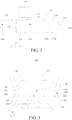
FIG. 2 is a side view ofFIG. 1 ; -
FIG. 3 is a schematic diagram of a combination of a lid and a drawer inFIG. 1 ; -
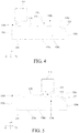
FIG. 4 is a side view ofFIG. 3 ; -
FIG. 5 is a diagram showing an effect of a lid and a drawer located within the storage compartment inFIG. 1 ; -
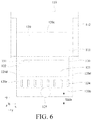
FIG. 6 is a top view ofFIG. 1 ; -
FIG. 7 is a side view of a partial structure of another refrigerator according to an embodiment of the utility model; -
FIG. 8 is an exploded view of a lid inFIG. 1 ; - 100-refrigerator; 110-storage compartment; 111-block; 112-guide rail; 120-drawer; 120a-bottom wall; 120b-front wall; 120c-rear wall; 120d-side wall; 120e-top wall; 121-opening; 122-upper edge; 123-handle portion; 124-air duct; 125-controller; 130-lid; 130a-front end of lid; 130b-rear end of lid; 131-handle; 132-stop; 133-frame; 134-viewing port; 135-transparent member; 136-sealing strip; gap-gap; x-width direction of the refrigerator; y-depth direction of the refrigerator; z-height direction of the refrigerator
- Those skilled in the art understand that, as the background art states, drawers in existing refrigerators are all designed without lids, and consequently products cannot be stored in the drawer in a sealed manner.
- In order to solve the foregoing technical problems, an embodiment of the utility model provides a refrigerator, including: a storage compartment; a drawer located within the storage compartment, the drawer having an opening facing upward; a lid for uncovering or covering the opening, the lid being slidably supported at an upper portion of the drawer, when the drawer is pulled out of the storage compartment, the lid being pulled out with the drawer while keeping the opening covered and sliding relative to the drawer to be pushed back into the storage compartment to uncover the opening; and a block located within the storage compartment, configured to prevent the lid from continuing moving rearward to keep the lid supported on the drawer that is pulled out, and enable the lid to cover the opening when the drawer is pushed into the storage compartment.
- Those skilled in the art will understand that the solutions of embodiments of the utility model provide a refrigerator with a drawer. When the drawer is located within the storage compartment of the refrigerator and is pulled out of the storage compartment, the opening of the drawer is covered by a lid supported on the drawer, which can effectively improve sealing performance of the drawer and prevent a stored product in the drawer from being directly exposed within the storage compartment and being tainted with other stored products in the storage compartment, and can help improve food hygiene.
- Further, when the drawer is pulled out of the storage compartment, the lid can be pushed by a user to slide forward and rearward relative to the drawer to uncover the opening of the drawer, which is convenient for the user to take the stored product in the drawer. Further, with the design for the block, the lid can be prevented from excessively moving rearward until detaching from the drawer, so that it can be ensured that the lid is always supported on the drawer while sliding forward and rearward. Further, because the block is disposed within the storage compartment, when the opening of the drawer is pushed back into the storage compartment in an uncovered state, the user does not need to cover the lid intentionally, but the opening of the drawer can be covered automatically through cooperation of the lid with the block as the drawer is pushed back into the storage compartment, so that the drawer is in a sealed state within the storage compartment.
- In order to make the foregoing objective, features, and advantages of the utility model more clearly and easier to understand, specific embodiments of the utility model are described in details below with reference to accompanying drawings.
-
FIG. 1 is a partial schematic structural diagram of a refrigerator according to an embodiment of the utility model. In order to more clearly illustrate technical features of this embodiment,FIG. 1 mainly takes an example of a storage compartment of the refrigerator and a drawer disposed therein, and further describes a specific structure of the drawer. - It should be noted that the design of this embodiment may also be applied to a refrigeration apparatus such as a refrigerated cabinet or a freezer in which stored products need to be stored in a separated and sealed manner.
- In particular, in this embodiment, the
refrigerator 100 may further include: astorage compartment 110; and adrawer 120 located within thestorage compartment 110. - A size of the
drawer 120 may be adapted to an accommodation space of thestorage compartment 110. For example, thestorage compartment 110 may be adapted to accommodate one ormore drawers 120. - More particular, with reference to
FIG. 1 andFIG. 2 (thestorage compartment 110 is omitted inFIG. 2 ), thedrawer 120 may include abottom wall 120a, afront wall 120b, arear wall 120c, and a pair ofside walls 120d, and may further include an accommodation space enclosed by thebottom wall 120a, thefront wall 120b, the pair ofside walls 120d, and therear wall 120c, and thedrawer 120 may have anopening 121 facing upward, theopening 121 exposing the accommodation space. - For example, the
drawer 120 may be adapted to accommodate stored products, and a user may take the stored products placed in the accommodation space from theopening 121. Alternatively, the user may also place the stored products from theopening 121 in the accommodation space. - For convenience of description, in this embodiment, a width direction of the
refrigerator 100 is set to a direction x, a depth direction of therefrigerator 100 is set to a direction y, and a height direction of therefrigerator 100 is set to a direction z. A direction from inside to outside of thestorage compartment 110 is a positive direction of the direction y (that is, the direction +y in the figure). In other words, a direction in which thedrawer 120 is pulled out of thestorage compartment 110 is the positive direction of the direction y. - For example, a plurality of the
drawers 120 may be arranged side by side along the direction x, the direction y, and/or the direction z within thestorage compartment 110. - Next, one
drawer 120 accommodated within thestorage compartment 110 is used as an example for specific description. - In one or more embodiments, still referring to
FIG. 1 andFIG. 2 , therefrigerator 100 may further include alid 130 for uncovering or covering theopening 121, thelid 130 being slidably supported on the upper portion of thedrawer 120. The upper portion of thedrawer 120 may refer to anupper edge 122 of at least one of thefront wall 120b, a pair ofside walls 120d, and arear wall 120c of thedrawer 120. - Further, referring to
FIG. 3 andFIG. 4 , when thedrawer 120 is pulled out of thestorage compartment 110, thelid 130 is pulled out with thedrawer 120 while keeping theopening 121 covered. A pull-out direction is the direction +y shown in the figure. - Further, referring to
FIG. 1 andFIG. 2 , thelid 130 may slide relative to thedrawer 120 to be pushed back into thestorage compartment 110 to uncover theopening 121. A pull-back direction is the direction -y shown in the figure. - Further, with reference to
FIG. 1 to FIG. 4 , therefrigerator 100 may further include: ablock 111 located within thestorage compartment 110, configured to prevent thelid 130 from continuing moving rearward to keep thelid 130 supported on thedrawer 120 that is pulled out, and when thedrawer 120 is pushed into thestorage compartment 110, enable thelid 130 to cover theopening 121. - In one or more embodiments, the
block 111 may be fixed to an inner wall of thestorage compartment 110 and extend to an upper side of thelid 130, to effectively prevent thelid 130 supported on theupper edge 122 of thedrawer 120 from excessively moving rearward, and control thelid 130 to cover theopening 121 of thedrawer 120 when thedrawer 120 is pushed back into thestorage compartment 110. - For example, referring to
FIG. 1 to FIG. 4 , theblock 111 may be disposed on an inner top wall of thestorage compartment 110 and extend downward (that is, along a negative direction of the direction z in the figure) to the upper side of thelid 130. - In a typical application scenario, referring to
FIG. 5 , thedrawer 120 may initially be located within thestorage compartment 110, and thelid 130 is supported on theupper edge 122 of thedrawer 120 while keeping theopening 121 of thedrawer 120 covered. - Further, the
front wall 120b of thedrawer 120 may be provided with ahandle portion 123, and the user can pull thedrawer 120 along the direction +y through thehandle portion 123 to pull thedrawer 120 out of thestorage compartment 110. - When the
drawer 120 is pulled out of thestorage compartment 110, thelid 130 keeps theopening 121 of thedrawer 120 covered, as shown inFIG. 4 . - Further, an upper surface of the
lid 130 may be provided with ahandle 131, and the user can push thelid 130 along the direction -y through thehandle 131 to uncover theopening 121 of thedrawer 120, as shown inFIG. 2 . Thehandle 131 extends from the upper surface of thelid 130 toward the direction z. In other words, at an angle shown inFIG. 2 , thehandle 131 protrudes from the upper surface of thelid 130. - The
lid 130 slides rearward relative to thedrawer 120 at an upper portion of thedrawer 120 until thehandle 131 abuts against theblock 111, to prevent thelid 130 from continuing sliding rearward. - Further, when the
opening 121 of thedrawer 120 is required to be covered, the user may pull thelid 130 along the direction +y through thehandle 131, to manually cover theopening 121 of thedrawer 120. Then, thedrawer 120 is pushed along the direction -y to push thedrawer 120 together with thelid 130 supported thereon back into thestorage compartment 110, so that thedrawer 120 and thelid 130 return to a state shown inFIG. 5 . - Alternatively, when the
opening 121 of thedrawer 120 is required to be covered, the user may also push thedrawer 120 directly along the direction -y in a state shown inFIG. 2 to push thedrawer 120 back into thestorage compartment 110. In addition, because thehandle 131 of thelid 130 abuts against theblock 111, thelid 130 does not move rearward together with thedrawer 120 when thedrawer 120 moves rearward. Accordingly, through rearward movement of thedrawer 120, thelid 130 can gradually cover theopening 121 of thedrawer 120 until thedrawer 120 and thelid 130 return to the state as shown inFIG. 5 . - As a variant, the
block 111 may also be disposed on an inner side wall or on a rear wall of thestorage compartment 110 and extend to the upper side of thelid 130. The upper side of thelid 130 may refer to an upper space of thelid 130 along the direction z. - In one or more embodiments, the
block 111 may extend to an upper surface of thelid 130, and accordingly, thehandle 131 only needs to protrude by a small size toward the direction z to abut against theblock 111. - In one or more alternative examples, referring to
FIG. 7 , there may be a gap between theblock 111 and a surface (that is, the upper surface) of thelid 130, to improve a sliding effect of thelid 130 and prevent thelid 130 and/or theblock 111 from being damaged by unlubricated friction with theblock 111 when thelid 130 slides forward and rearward, thereby optimizing user experience. - Further, a height of the gap along the direction z may be set to be small enough to prevent a
rear end 130b of thelid 130 from rotating downward when thelid 130 is pushed back. Rotating downward refers to rotating along a reverse direction of the direction z. - In one or more embodiments, the
lid 130 may have astop 132, and thelid 130 moves rearward relative to thedrawer 120 until thestop 132 abuts against theblock 111, to prevent thelid 130 from continuing moving rearward. - Accordingly, through cooperation of the
block 111 with thestop 132, when thelid 130 is pushed toward thestorage compartment 110 to uncover theopening 121 of thedrawer 120, thelid 130 can be prevented from excessively moving rearward until detaching from thedrawer 120, so that it can be ensured that thelid 130 is always supported on thedrawer 120. - Further, when the
drawer 120 is pushed rearward into thestorage compartment 110 when theopening 121 is uncovered, as thedrawer 120 moves rearward, thelid 130 is confined to an original place because thestop 132 abuts against theblock 111 thereof. Accordingly, when thedrawer 120 moves into thestorage compartment 110, thelid 130 can be naturally covered on thedrawer 120, and theopening 121 of thedrawer 120 is covered. - For example, referring to
FIG. 2 , a height of thestop 132 along the direction z may be greater than a gap between theblock 111 and thelid 130, to ensure that thestop 132 abuts against theblock 111 when thestop 132 moves to theblock 111 along the direction - y relative to thedrawer 120 with thelid 130, to prevent thelid 130 from continuing moving rearward. - In one or more embodiments, the
stop 132 may be connected to thehandle 131 of thelid 130, which facilitates overall aesthetic appearance of thedrawer 120, while simplifying a structure and being easy to manufacture. - For example, the
stop 132 and/or thehandle 131 may be fixed to the upper surface of thelid 130 in a manner of bonding, interference fit, or bolting. - Further, the
handle 131 and thestop 132 may be integrally formed. - For example, the
stop 132 may be considered as an extension of thehandle 131. Alternatively, thehandle 131 may replace thestop 132 to prevent thelid 130 from sliding rearward, and vice versa. - In one or more embodiments, by adjusting a specific location of the
handle 131 on thelid 130, and/or a specific location at which theblock 111 extends to the upper side of thelid 130, a distance that thelid 130 may slide rearward relative to thedrawer 120 can be adjusted, and an area in which theopening 121 is uncovered can be further adjusted. - For example, in order to uncover the
opening 121 as large as possible, thehandle 131 may be located at afront end 130a of the upper surface of thelid 130, thefront end 130a being one end close to afront wall 120b of thedrawer 120. Theblock 111 may extend to the upper side of thelid 130 and be close to an outer side (that is, one side close to of thefront wall 120b of thedrawer 120 when thedrawer 120 is located within the storage compartment 110) of thestorage compartment 110, to enable thelid 130 to slide rearward to substantially fully uncovering theopening 121 of thedrawer 120 when thedrawer 120 is pulled out of thestorage compartment 110, and prevent thelid 130 from moving until theopening 121 is completely covered when thedrawer 120 is pushed back into thestorage compartment 110. - In one or more embodiments, referring to
FIG. 8 , thelid 130 may include: aframe 133, theframe 133 enclosing aviewing port 134; and atransparent member 135, disposed within theviewing port 134 and connected to theframe 133. - Accordingly, when the
drawer 120 is pulled out of thestorage compartment 110, an interior of thedrawer 120 can be visually seen without pushing open thelid 130, and the user can accurately and quickly determine whether a stored product being sought is stored within thedrawer 120, thereby reducing the number of unnecessary uncovering and covering of thedrawer 120. In other words, the user can push open thelid 130 of thedrawer 120 to take the stored product after determining that the stored product to be taken is actually stored in thedrawer 120, instead of uncovering thelid 130 first and then determining whether the stored product is in thedrawer 120, which further reduces a possibility of odor tainting. - Preferably, the
transparent member 135 may be made of a glass material to enable thelid 130 to be pressed against theupper edge 122 of thedrawer 120 by its own weight while satisfying transparency of theviewing opening 134, thereby improving sealing performance of thedrawer 120. For example, thetransparent member 135 may be made of tempered glass. - In one or more embodiments, an area of the
viewing port 134 may occupy 60% to 90% of an area of theopening 121, to ensure that all corners inside thedrawer 120 can be clearly seen from theviewing port 134, thereby avoiding a visual blind zone. In a practical application, those skilled in the art can also adjust the area of theviewing port 134 to an appropriate size as needed to meet diversified needs of users. - In one or more embodiments, the
lid 130 may further include: a sealingstrip 136 fixed to a lower side of thelid 130, and contacting anupper edge 122 of thedrawer 120 when thelid 130 covers theopening 121, thereby forming a confined space within thedrawer 120, so that the sealing performance of thedrawer 120 becomes better. For example, the sealingstrip 136 may be fixed to theframe 133. - In one or more alternative examples, the
lid 130 may also be made of a heat-conducting material to conduct temperature through a physical property of a material, achieving a better freezing/unfreezing effect, so that partition storage and short-term sealed refrigeration can be implemented with a simple structural design. - For example, the
lid 130 may be made of a metal material with relatively good heat-conducting performance. - In one or more embodiments, the
drawer 120 may be made of a transparent material, such as a transparent plastic box, to help visually observe stored products within thedrawer 120. - In one or more embodiments, referring to
FIG. 1 ,FIG. 3 , andFIG. 6 , thedrawer 120 may have anair duct 124, a space inside thedrawer 120 being in communication with a space outside thedrawer 120 when theair duct 124 is opened, and the space inside thedrawer 120 being isolated from the space outside thedrawer 120 when the air duct (124) is closed. - Accordingly, a
separate air duct 124 designed on thedrawer 120 is beneficial to freely switch between partitioned storage and sealed storage, to meet diversified needs of users. - In a typical application scenario, the
lid 130 is used to cover theopening 121 of thedrawer 120 while closing theair duct 124, so that a separate confined space can be formed within thedrawer 120 to implement sealed storage. - In another typical application scenario, the
lid 130 is still used to cover theopening 121 of thedrawer 120 while opening theair duct 124, and thedrawer 120 can be used as a normal container. However, because other stored products within the storedcompartment 110 are isolated with each other, a stored space within thestorage compartment 110 can be separated, to implement partitioned storage. - In one or more embodiments, still referring to
FIG. 1 andFIG. 3 , thedrawer 120 may include abottom wall 120a, afront wall 120b, arear wall 120c, a pair ofside walls 120d, and atop wall 120e. Thetop wall 120e is located between theopening 121 and thefront wall 120b, and theair duct 124 may be located on thetop wall 120e of thedrawer 120. - Accordingly, when the
air duct 124 is opened, air inside thedrawer 120 can be quickly exchanged with air outside thedrawer 120, and when theair duct 124 is closed, it can be ensured that thedrawer 120 is in a relatively good sealed state. - Further, when the
drawer 120 is pulled out of thestorage compartment 110, theair duct 124 disposed on thetop wall 120e of thedrawer 120 enables the user to visually observe a current state of theair duct 124, so that the user can adjust theair duct 124 to be in an open/closed state as needed. - In one or more embodiments, the
drawer 120 may further have acontroller 125 connected to theair duct 124 to open or close theair duct 124. Accordingly, the user can control theair duct 124 to be in an open/closed state as needed to freely and flexibly switch the state of thedrawer 120 between the partitioned storage and the sealed storage. - For example, the
controller 125 may be a physical controller, which controls opening/closing of theair duct 124 in a mechanical manner. For another example, thecontroller 125 may further be an electronic controller, which controls the opening/closing of theair duct 124 by transmitting a signal. - Preferably, the
controller 125 may be located on thefront wall 120b of thedrawer 120 to facilitate user operation. For example, the user can manipulate thecontroller 125 without pulling thedrawer 120 out of thestorage compartment 110. - In one or more embodiments, the
controller 125 may further be configured to record storage time of the stored products within thedrawer 120. - In one or more embodiments, referring to
FIG. 6 , therefrigerator 100 may further include: aguide rail 112, configured to movably fix thedrawer 120 within thestorage compartment 110, thedrawer 120 being adapted to be pulled out or pushed back into thestorage compartment 110 along theguide rail 112. Accordingly, the user can conveniently pull out or push back thedrawer 120 as needed, preventing thedrawer 120 and/or thestorage compartment 110 from being damaged by unlubricated friction with an inner wall of thestorage compartment 110 when thedrawer 120 moves forward and rearward relative to thestorage compartment 110, which can help improve user experience. - In particular, the
guide rail 112 may include: a fixed rail fixed to an inner wall of thestorage compartment 110; and a movable rail fixed to an outer wall of thedrawer 120 and coupled to the fixed rail, the movable rail sliding forward and rearward relative to the fixed rail. Forward/rearward sliding refers to moving forward and rearward along directions ±y. - For example, the fixed rail may be fixed to a pair of inner side walls of the
storage compartment 110, and the movable rail is fixed to a pair ofside walls 120d of thedrawer 120. - For another example, the fixed rail may be fixed to a pair of inner side walls of the
storage compartment 110, and the movable rail is fixed to abottom wall 120a of thedrawer 120. - For example, the guide rail (also referred to as a sliding rail) 112 may be selected from a roller-type guide rail, a steel-ball-type guide rail, a gear-type guide rail, or a damping-type sliding rail. Those skilled in the art may also select other types of guide rails as needed, and details are not described herein.
- In one or more embodiments, the fixed rail may be fixed to the inner wall of the
storage compartment 110 in a bolting manner. Similarly, the movable rail may also be fixed to an outer wall of thedrawer 120 and coupled to the fixed rail in a bolting manner. - In one or more alternative example, the fixed rail and/or the movable rail may also be fixed to the inner wall of the
storage compartment 110 and/or the outer wall of thedrawer 120 respectively in a manner of interference fit, bonding, or the like. - Accordingly, according to the solutions of the embodiments, when the
drawer 120 is located within thestorage compartment 110 of therefrigerator 100 and when thedrawer 120 is pulled out of thestorage compartment 110, theopening 121 of thedrawer 120 is covered through thelid 130 supported on thedrawer 120, thereby effectively improving the sealing performance of thedrawer 120 and preventing the stored products within thedrawer 120 from being directly exposed within thestorage compartment 110 and being tainted with other stored products within thestorage compartment 110, which can help improve food hygiene. - Further, when the
drawer 120 is pulled out of thestorage compartment 110, thelid 130 may be pushed by the user to slide forward and rearward relative to thedrawer 120 to uncover theopening 121 of thedrawer 120, which is convenient for the user to take stored products within thedrawer 120. - Further, with the design of the
block 111, thelid 130 can be prevented from excessively moving rearward until detaching from thedrawer 120, so that it can be ensured that thelid 130 is always supported on thedrawer 120 while sliding forward and rearward. - Further, because the
block 111 is disposed within thestorage compartment 110, when theopening 121 of thedrawer 120 is pushed back into thestorage compartment 110 in an uncovered state, the user does not need to cover thelid 130 intentionally, but theopening 121 of thedrawer 120 may be covered automatically through cooperation of thelid 130 with theblock 111 as thedrawer 120 is pushed back into thestorage compartment 110, so that thedrawer 120 is in a sealed state within thestorage compartment 110. - Although the utility model is disclosed above, the utility model is not limited thereto. Various alterations and modifications may be made by a person skilled in the art without departing from the spirit and scope of the utility model, and thus the protection scope of the utility model should be subject to scope defined by the claims.
Claims (13)
- A refrigerator (100), characterized by comprising:a storage compartment (110);a drawer (120) located within the storage compartment (110), the drawer (120) having an opening (121) facing upward;a lid (130) for uncovering or covering the opening (121), the lid (130) being slidably supported on an upper portion of the drawer (120), and when the drawer (120) is pulled out of the storage compartment (110), the lid (130) being pulled out with the drawer (120) while keeping the opening (121) covered and sliding relative to the drawer (120) to be pushed back into the storage compartment (110) to uncover the opening (121);a block (111) located within the storage compartment (110), configured to: prevent the lid (130) from continuing moving rearward to keep the lid (130) supported on the drawer (120) that is pulled out, and when the drawer (120) is pushed into the storage compartment (110), enable the lid (130) to cover the opening (121).
- The refrigerator (100) according to claim 1, characterized in that the lid (130) comprises: a frame (133), the frame (133) enclosing a viewing port (134); and a transparent member (135) disposed within the viewing port (134) and connected to the frame (133).
- The refrigerator (100) according to claim 2, characterized in that an area of the viewing port (134) accounts for 60% to 90% of an area of the opening (121).
- The refrigerator (100) according to anyone of claims 1 to 3, characterized in that the lid (130) further comprises:
a sealing strip (136) fixed to a lower side of the lid (130) and contacting an upper edge (122) of the drawer (120) when the lid (130) covers the opening (121). - The refrigerator (100) according to anyone of claims 1 to 4, characterized in that the lid (130) is made of a heat-conducting material.
- The refrigerator (100) according to anyone of claims 1 to 5, characterized in that the drawer (120) comprises:
an air duct (124), a space inside the drawer (120) being in communication with a space outside the drawer (120) when the air duct (124) is opened, and the space inside the drawer (120) being isolated from the space outside the drawer (120) when the air duct (124) is closed. - The refrigerator (100) according to claim 6, characterized in that the drawer (120) comprises a bottom wall (120a), a front wall (120b), a rear wall (120c), a pair of side walls (120d), and a top wall (120e), the top wall (120e) being located between the opening (121) and the front wall (120b), and the air duct (124) being located on the top wall (120e) of the drawer (120).
- The refrigerator (100) according to claim 6, characterized in that the drawer (120) further comprises:
a controller (125) connected to the air duct (124) to open or close the air duct (124). - The refrigerator (100) according to anyone of claims 1 to 8, characterized in that the lid (130) has a stop (132), the lid (130) moving rearward relative to the drawer (120) until the stop (132) abuts against the block (111) to prevent the lid (130) from continuing moving rearward.
- The refrigerator (100) according to claim 9, characterized in that the stop (132) is connected to a handle (131) of the lid (130).
- The refrigerator (100) according to anyone of claims 1 to 10, characterized in that the block (111) is fixed to an inner wall of the storage compartment (110) and extends to an upper side of the lid (130).
- The refrigerator (100) according to anyone of claims 1 to 12, characterized in that there is a gap between the block (111) and a surface of the lid (130).
- The refrigerator (100) according to anyone of claims 1 to 12, characterized by further comprising:
a guide rail (112), configured to movably fix the drawer (120) within the storage compartment (110), the drawer (120) being adapted to be pulled out of or pushed back into the storage compartment (110) along the guide rail (112).
Applications Claiming Priority (1)
| Application Number | Priority Date | Filing Date | Title |
|---|---|---|---|
| CN201821476727.7U CN209027182U (en) | 2018-09-10 | 2018-09-10 | A kind of refrigerator |
Publications (2)
| Publication Number | Publication Date |
|---|---|
| EP3620733A1 true EP3620733A1 (en) | 2020-03-11 |
| EP3620733B1 EP3620733B1 (en) | 2022-06-29 |
Family
ID=66904370
Family Applications (1)
| Application Number | Title | Priority Date | Filing Date |
|---|---|---|---|
| EP19191965.3A Active EP3620733B1 (en) | 2018-09-10 | 2019-08-15 | Refrigerator |
Country Status (2)
| Country | Link |
|---|---|
| EP (1) | EP3620733B1 (en) |
| CN (1) | CN209027182U (en) |
Families Citing this family (2)
| Publication number | Priority date | Publication date | Assignee | Title |
|---|---|---|---|---|
| US11680359B2 (en) * | 2019-12-12 | 2023-06-20 | Whirlpool Corporation | Laundry treating appliance having a tub with a closure |
| CN113074492B (en) * | 2020-01-03 | 2024-01-12 | 博西华家用电器有限公司 | a household appliance |
Citations (3)
| Publication number | Priority date | Publication date | Assignee | Title |
|---|---|---|---|---|
| JP2000039256A (en) * | 1998-07-27 | 2000-02-08 | Fujitsu General Ltd | refrigerator |
| EP1564512A1 (en) * | 2004-02-10 | 2005-08-17 | Electrolux Home Products Corporation N.V. | Shelf assembly for a refrigerating apparatus |
| US20150059399A1 (en) * | 2013-09-03 | 2015-03-05 | Lg Electronics Inc. | Refrigerator |
-
2018
- 2018-09-10 CN CN201821476727.7U patent/CN209027182U/en active Active
-
2019
- 2019-08-15 EP EP19191965.3A patent/EP3620733B1/en active Active
Patent Citations (3)
| Publication number | Priority date | Publication date | Assignee | Title |
|---|---|---|---|---|
| JP2000039256A (en) * | 1998-07-27 | 2000-02-08 | Fujitsu General Ltd | refrigerator |
| EP1564512A1 (en) * | 2004-02-10 | 2005-08-17 | Electrolux Home Products Corporation N.V. | Shelf assembly for a refrigerating apparatus |
| US20150059399A1 (en) * | 2013-09-03 | 2015-03-05 | Lg Electronics Inc. | Refrigerator |
Also Published As
| Publication number | Publication date |
|---|---|
| EP3620733B1 (en) | 2022-06-29 |
| CN209027182U (en) | 2019-06-25 |
Similar Documents
| Publication | Publication Date | Title |
|---|---|---|
| US2711944A (en) | Refrigerator drawer and latch | |
| US5193892A (en) | Food compartment for refrigerators | |
| EP2420776A2 (en) | Refrigerator | |
| EP3152502B1 (en) | Refrigerator | |
| EP3620737A1 (en) | Refrigerator | |
| US2843441A (en) | Storage cabinet drawer assembly | |
| JP2009186141A (en) | refrigerator | |
| CN211233534U (en) | Storage box, storage box assembly and refrigeration equipment | |
| KR101995427B1 (en) | Refrigerator | |
| KR20100008104A (en) | A vegetable box for refrigerator and refrigerator having the same | |
| EP3620733B1 (en) | Refrigerator | |
| CN102124289A (en) | Refrigerator | |
| JP2000292054A (en) | Container for refrigerator | |
| KR20110080523A (en) | Refrigerator with drawer compartment with cover assembly | |
| US11215391B1 (en) | Staged access door for a home appliance | |
| CN104279830B (en) | The combination of quick-freezing drawer and refrigerator | |
| CN117280173A (en) | Components for food storage with slide-out shelves | |
| EP3620736A1 (en) | Refrigerator | |
| KR101055737B1 (en) | Kimchi Refrigerator | |
| JP4483032B2 (en) | Refrigerator storage container | |
| CN101231110B (en) | Refrigerator door having multi-door family taproom | |
| US20170276424A1 (en) | Storage Assembly for an Appliance | |
| JPS6349675Y2 (en) | ||
| JP4382278B2 (en) | Storage container for refrigerator | |
| KR100785117B1 (en) | Auto Open Storage Container |
Legal Events
| Date | Code | Title | Description |
|---|---|---|---|
| PUAI | Public reference made under article 153(3) epc to a published international application that has entered the european phase |
Free format text: ORIGINAL CODE: 0009012 |
|
| STAA | Information on the status of an ep patent application or granted ep patent |
Free format text: STATUS: THE APPLICATION HAS BEEN PUBLISHED |
|
| AK | Designated contracting states |
Kind code of ref document: A1 Designated state(s): AL AT BE BG CH CY CZ DE DK EE ES FI FR GB GR HR HU IE IS IT LI LT LU LV MC MK MT NL NO PL PT RO RS SE SI SK SM TR |
|
| AX | Request for extension of the european patent |
Extension state: BA ME |
|
| STAA | Information on the status of an ep patent application or granted ep patent |
Free format text: STATUS: REQUEST FOR EXAMINATION WAS MADE |
|
| 17P | Request for examination filed |
Effective date: 20200911 |
|
| RBV | Designated contracting states (corrected) |
Designated state(s): AL AT BE BG CH CY CZ DE DK EE ES FI FR GB GR HR HU IE IS IT LI LT LU LV MC MK MT NL NO PL PT RO RS SE SI SK SM TR |
|
| RIC1 | Information provided on ipc code assigned before grant |
Ipc: F25D 25/02 20060101AFI20220114BHEP |
|
| GRAP | Despatch of communication of intention to grant a patent |
Free format text: ORIGINAL CODE: EPIDOSNIGR1 |
|
| STAA | Information on the status of an ep patent application or granted ep patent |
Free format text: STATUS: GRANT OF PATENT IS INTENDED |
|
| INTG | Intention to grant announced |
Effective date: 20220225 |
|
| GRAS | Grant fee paid |
Free format text: ORIGINAL CODE: EPIDOSNIGR3 |
|
| GRAA | (expected) grant |
Free format text: ORIGINAL CODE: 0009210 |
|
| STAA | Information on the status of an ep patent application or granted ep patent |
Free format text: STATUS: THE PATENT HAS BEEN GRANTED |
|
| AK | Designated contracting states |
Kind code of ref document: B1 Designated state(s): AL AT BE BG CH CY CZ DE DK EE ES FI FR GB GR HR HU IE IS IT LI LT LU LV MC MK MT NL NO PL PT RO RS SE SI SK SM TR |
|
| REG | Reference to a national code |
Ref country code: CH Ref legal event code: EP |
|
| REG | Reference to a national code |
Ref country code: AT Ref legal event code: REF Ref document number: 1501604 Country of ref document: AT Kind code of ref document: T Effective date: 20220715 |
|
| REG | Reference to a national code |
Ref country code: IE Ref legal event code: FG4D |
|
| REG | Reference to a national code |
Ref country code: DE Ref legal event code: R096 Ref document number: 602019016357 Country of ref document: DE |
|
| REG | Reference to a national code |
Ref country code: LT Ref legal event code: MG9D |
|
| PG25 | Lapsed in a contracting state [announced via postgrant information from national office to epo] |
Ref country code: SE Free format text: LAPSE BECAUSE OF FAILURE TO SUBMIT A TRANSLATION OF THE DESCRIPTION OR TO PAY THE FEE WITHIN THE PRESCRIBED TIME-LIMIT Effective date: 20220629 Ref country code: NO Free format text: LAPSE BECAUSE OF FAILURE TO SUBMIT A TRANSLATION OF THE DESCRIPTION OR TO PAY THE FEE WITHIN THE PRESCRIBED TIME-LIMIT Effective date: 20220929 Ref country code: LT Free format text: LAPSE BECAUSE OF FAILURE TO SUBMIT A TRANSLATION OF THE DESCRIPTION OR TO PAY THE FEE WITHIN THE PRESCRIBED TIME-LIMIT Effective date: 20220629 Ref country code: HR Free format text: LAPSE BECAUSE OF FAILURE TO SUBMIT A TRANSLATION OF THE DESCRIPTION OR TO PAY THE FEE WITHIN THE PRESCRIBED TIME-LIMIT Effective date: 20220629 Ref country code: GR Free format text: LAPSE BECAUSE OF FAILURE TO SUBMIT A TRANSLATION OF THE DESCRIPTION OR TO PAY THE FEE WITHIN THE PRESCRIBED TIME-LIMIT Effective date: 20220930 Ref country code: FI Free format text: LAPSE BECAUSE OF FAILURE TO SUBMIT A TRANSLATION OF THE DESCRIPTION OR TO PAY THE FEE WITHIN THE PRESCRIBED TIME-LIMIT Effective date: 20220629 Ref country code: BG Free format text: LAPSE BECAUSE OF FAILURE TO SUBMIT A TRANSLATION OF THE DESCRIPTION OR TO PAY THE FEE WITHIN THE PRESCRIBED TIME-LIMIT Effective date: 20220929 |
|
| REG | Reference to a national code |
Ref country code: NL Ref legal event code: MP Effective date: 20220629 |
|
| REG | Reference to a national code |
Ref country code: AT Ref legal event code: MK05 Ref document number: 1501604 Country of ref document: AT Kind code of ref document: T Effective date: 20220629 |
|
| PG25 | Lapsed in a contracting state [announced via postgrant information from national office to epo] |
Ref country code: RS Free format text: LAPSE BECAUSE OF FAILURE TO SUBMIT A TRANSLATION OF THE DESCRIPTION OR TO PAY THE FEE WITHIN THE PRESCRIBED TIME-LIMIT Effective date: 20220629 Ref country code: LV Free format text: LAPSE BECAUSE OF FAILURE TO SUBMIT A TRANSLATION OF THE DESCRIPTION OR TO PAY THE FEE WITHIN THE PRESCRIBED TIME-LIMIT Effective date: 20220629 |
|
| PG25 | Lapsed in a contracting state [announced via postgrant information from national office to epo] |
Ref country code: NL Free format text: LAPSE BECAUSE OF FAILURE TO SUBMIT A TRANSLATION OF THE DESCRIPTION OR TO PAY THE FEE WITHIN THE PRESCRIBED TIME-LIMIT Effective date: 20220629 |
|
| PG25 | Lapsed in a contracting state [announced via postgrant information from national office to epo] |
Ref country code: SM Free format text: LAPSE BECAUSE OF FAILURE TO SUBMIT A TRANSLATION OF THE DESCRIPTION OR TO PAY THE FEE WITHIN THE PRESCRIBED TIME-LIMIT Effective date: 20220629 Ref country code: SK Free format text: LAPSE BECAUSE OF FAILURE TO SUBMIT A TRANSLATION OF THE DESCRIPTION OR TO PAY THE FEE WITHIN THE PRESCRIBED TIME-LIMIT Effective date: 20220629 Ref country code: RO Free format text: LAPSE BECAUSE OF FAILURE TO SUBMIT A TRANSLATION OF THE DESCRIPTION OR TO PAY THE FEE WITHIN THE PRESCRIBED TIME-LIMIT Effective date: 20220629 Ref country code: PT Free format text: LAPSE BECAUSE OF FAILURE TO SUBMIT A TRANSLATION OF THE DESCRIPTION OR TO PAY THE FEE WITHIN THE PRESCRIBED TIME-LIMIT Effective date: 20221031 Ref country code: ES Free format text: LAPSE BECAUSE OF FAILURE TO SUBMIT A TRANSLATION OF THE DESCRIPTION OR TO PAY THE FEE WITHIN THE PRESCRIBED TIME-LIMIT Effective date: 20220629 Ref country code: EE Free format text: LAPSE BECAUSE OF FAILURE TO SUBMIT A TRANSLATION OF THE DESCRIPTION OR TO PAY THE FEE WITHIN THE PRESCRIBED TIME-LIMIT Effective date: 20220629 Ref country code: AT Free format text: LAPSE BECAUSE OF FAILURE TO SUBMIT A TRANSLATION OF THE DESCRIPTION OR TO PAY THE FEE WITHIN THE PRESCRIBED TIME-LIMIT Effective date: 20220629 |
|
| PG25 | Lapsed in a contracting state [announced via postgrant information from national office to epo] |
Ref country code: PL Free format text: LAPSE BECAUSE OF FAILURE TO SUBMIT A TRANSLATION OF THE DESCRIPTION OR TO PAY THE FEE WITHIN THE PRESCRIBED TIME-LIMIT Effective date: 20220629 Ref country code: IS Free format text: LAPSE BECAUSE OF FAILURE TO SUBMIT A TRANSLATION OF THE DESCRIPTION OR TO PAY THE FEE WITHIN THE PRESCRIBED TIME-LIMIT Effective date: 20221029 |
|
| REG | Reference to a national code |
Ref country code: DE Ref legal event code: R097 Ref document number: 602019016357 Country of ref document: DE |
|
| PG25 | Lapsed in a contracting state [announced via postgrant information from national office to epo] |
Ref country code: MC Free format text: LAPSE BECAUSE OF FAILURE TO SUBMIT A TRANSLATION OF THE DESCRIPTION OR TO PAY THE FEE WITHIN THE PRESCRIBED TIME-LIMIT Effective date: 20220629 Ref country code: AL Free format text: LAPSE BECAUSE OF FAILURE TO SUBMIT A TRANSLATION OF THE DESCRIPTION OR TO PAY THE FEE WITHIN THE PRESCRIBED TIME-LIMIT Effective date: 20220629 |
|
| REG | Reference to a national code |
Ref country code: CH Ref legal event code: PL |
|
| PG25 | Lapsed in a contracting state [announced via postgrant information from national office to epo] |
Ref country code: LU Free format text: LAPSE BECAUSE OF NON-PAYMENT OF DUE FEES Effective date: 20220815 Ref country code: LI Free format text: LAPSE BECAUSE OF NON-PAYMENT OF DUE FEES Effective date: 20220831 Ref country code: DK Free format text: LAPSE BECAUSE OF FAILURE TO SUBMIT A TRANSLATION OF THE DESCRIPTION OR TO PAY THE FEE WITHIN THE PRESCRIBED TIME-LIMIT Effective date: 20220629 Ref country code: CZ Free format text: LAPSE BECAUSE OF FAILURE TO SUBMIT A TRANSLATION OF THE DESCRIPTION OR TO PAY THE FEE WITHIN THE PRESCRIBED TIME-LIMIT Effective date: 20220629 Ref country code: CH Free format text: LAPSE BECAUSE OF NON-PAYMENT OF DUE FEES Effective date: 20220831 |
|
| REG | Reference to a national code |
Ref country code: BE Ref legal event code: MM Effective date: 20220831 |
|
| PLBE | No opposition filed within time limit |
Free format text: ORIGINAL CODE: 0009261 |
|
| STAA | Information on the status of an ep patent application or granted ep patent |
Free format text: STATUS: NO OPPOSITION FILED WITHIN TIME LIMIT |
|
| 26N | No opposition filed |
Effective date: 20230330 |
|
| PG25 | Lapsed in a contracting state [announced via postgrant information from national office to epo] |
Ref country code: IE Free format text: LAPSE BECAUSE OF NON-PAYMENT OF DUE FEES Effective date: 20220815 Ref country code: FR Free format text: LAPSE BECAUSE OF NON-PAYMENT OF DUE FEES Effective date: 20220829 |
|
| PG25 | Lapsed in a contracting state [announced via postgrant information from national office to epo] |
Ref country code: SI Free format text: LAPSE BECAUSE OF FAILURE TO SUBMIT A TRANSLATION OF THE DESCRIPTION OR TO PAY THE FEE WITHIN THE PRESCRIBED TIME-LIMIT Effective date: 20220629 |
|
| PG25 | Lapsed in a contracting state [announced via postgrant information from national office to epo] |
Ref country code: BE Free format text: LAPSE BECAUSE OF NON-PAYMENT OF DUE FEES Effective date: 20220831 |
|
| PG25 | Lapsed in a contracting state [announced via postgrant information from national office to epo] |
Ref country code: IT Free format text: LAPSE BECAUSE OF FAILURE TO SUBMIT A TRANSLATION OF THE DESCRIPTION OR TO PAY THE FEE WITHIN THE PRESCRIBED TIME-LIMIT Effective date: 20220629 |
|
| PG25 | Lapsed in a contracting state [announced via postgrant information from national office to epo] |
Ref country code: HU Free format text: LAPSE BECAUSE OF FAILURE TO SUBMIT A TRANSLATION OF THE DESCRIPTION OR TO PAY THE FEE WITHIN THE PRESCRIBED TIME-LIMIT; INVALID AB INITIO Effective date: 20190815 |
|
| GBPC | Gb: european patent ceased through non-payment of renewal fee |
Effective date: 20230815 |
|
| PG25 | Lapsed in a contracting state [announced via postgrant information from national office to epo] |
Ref country code: CY Free format text: LAPSE BECAUSE OF FAILURE TO SUBMIT A TRANSLATION OF THE DESCRIPTION OR TO PAY THE FEE WITHIN THE PRESCRIBED TIME-LIMIT Effective date: 20220629 |
|
| PG25 | Lapsed in a contracting state [announced via postgrant information from national office to epo] |
Ref country code: MK Free format text: LAPSE BECAUSE OF FAILURE TO SUBMIT A TRANSLATION OF THE DESCRIPTION OR TO PAY THE FEE WITHIN THE PRESCRIBED TIME-LIMIT Effective date: 20220629 |
|
| PG25 | Lapsed in a contracting state [announced via postgrant information from national office to epo] |
Ref country code: TR Free format text: LAPSE BECAUSE OF FAILURE TO SUBMIT A TRANSLATION OF THE DESCRIPTION OR TO PAY THE FEE WITHIN THE PRESCRIBED TIME-LIMIT Effective date: 20220629 |
|
| PG25 | Lapsed in a contracting state [announced via postgrant information from national office to epo] |
Ref country code: GB Free format text: LAPSE BECAUSE OF NON-PAYMENT OF DUE FEES Effective date: 20230815 |
|
| PG25 | Lapsed in a contracting state [announced via postgrant information from national office to epo] |
Ref country code: GB Free format text: LAPSE BECAUSE OF NON-PAYMENT OF DUE FEES Effective date: 20230815 |
|
| PG25 | Lapsed in a contracting state [announced via postgrant information from national office to epo] |
Ref country code: MT Free format text: LAPSE BECAUSE OF FAILURE TO SUBMIT A TRANSLATION OF THE DESCRIPTION OR TO PAY THE FEE WITHIN THE PRESCRIBED TIME-LIMIT Effective date: 20220629 |
|
| PG25 | Lapsed in a contracting state [announced via postgrant information from national office to epo] |
Ref country code: BG Free format text: LAPSE BECAUSE OF FAILURE TO SUBMIT A TRANSLATION OF THE DESCRIPTION OR TO PAY THE FEE WITHIN THE PRESCRIBED TIME-LIMIT Effective date: 20220629 |
|
| PG25 | Lapsed in a contracting state [announced via postgrant information from national office to epo] |
Ref country code: BG Free format text: LAPSE BECAUSE OF FAILURE TO SUBMIT A TRANSLATION OF THE DESCRIPTION OR TO PAY THE FEE WITHIN THE PRESCRIBED TIME-LIMIT Effective date: 20220629 |
|
| PGFP | Annual fee paid to national office [announced via postgrant information from national office to epo] |
Ref country code: DE Payment date: 20250831 Year of fee payment: 7 |