EP3620637A1 - Control method for internal combustion engine and control device for internal combustion engine - Google Patents
Control method for internal combustion engine and control device for internal combustion engine Download PDFInfo
- Publication number
- EP3620637A1 EP3620637A1 EP17908545.1A EP17908545A EP3620637A1 EP 3620637 A1 EP3620637 A1 EP 3620637A1 EP 17908545 A EP17908545 A EP 17908545A EP 3620637 A1 EP3620637 A1 EP 3620637A1
- Authority
- EP
- European Patent Office
- Prior art keywords
- compression ratio
- point
- cylinder bore
- temperature
- internal combustion
- Prior art date
- Legal status (The legal status is an assumption and is not a legal conclusion. Google has not performed a legal analysis and makes no representation as to the accuracy of the status listed.)
- Granted
Links
Images


Classifications
-
- F—MECHANICAL ENGINEERING; LIGHTING; HEATING; WEAPONS; BLASTING
- F02—COMBUSTION ENGINES; HOT-GAS OR COMBUSTION-PRODUCT ENGINE PLANTS
- F02B—INTERNAL-COMBUSTION PISTON ENGINES; COMBUSTION ENGINES IN GENERAL
- F02B75/00—Other engines
- F02B75/04—Engines with variable distances between pistons at top dead-centre positions and cylinder heads
-
- F—MECHANICAL ENGINEERING; LIGHTING; HEATING; WEAPONS; BLASTING
- F02—COMBUSTION ENGINES; HOT-GAS OR COMBUSTION-PRODUCT ENGINE PLANTS
- F02D—CONTROLLING COMBUSTION ENGINES
- F02D15/00—Varying compression ratio
- F02D15/02—Varying compression ratio by alteration or displacement of piston stroke
-
- F—MECHANICAL ENGINEERING; LIGHTING; HEATING; WEAPONS; BLASTING
- F02—COMBUSTION ENGINES; HOT-GAS OR COMBUSTION-PRODUCT ENGINE PLANTS
- F02D—CONTROLLING COMBUSTION ENGINES
- F02D35/00—Controlling engines, dependent on conditions exterior or interior to engines, not otherwise provided for
- F02D35/02—Controlling engines, dependent on conditions exterior or interior to engines, not otherwise provided for on interior conditions
- F02D35/025—Controlling engines, dependent on conditions exterior or interior to engines, not otherwise provided for on interior conditions by determining temperatures inside the cylinder, e.g. combustion temperatures
- F02D35/026—Controlling engines, dependent on conditions exterior or interior to engines, not otherwise provided for on interior conditions by determining temperatures inside the cylinder, e.g. combustion temperatures using an estimation
-
- F—MECHANICAL ENGINEERING; LIGHTING; HEATING; WEAPONS; BLASTING
- F02—COMBUSTION ENGINES; HOT-GAS OR COMBUSTION-PRODUCT ENGINE PLANTS
- F02D—CONTROLLING COMBUSTION ENGINES
- F02D41/00—Electrical control of supply of combustible mixture or its constituents
- F02D41/02—Circuit arrangements for generating control signals
- F02D41/04—Introducing corrections for particular operating conditions
- F02D41/06—Introducing corrections for particular operating conditions for engine starting or warming up
-
- F—MECHANICAL ENGINEERING; LIGHTING; HEATING; WEAPONS; BLASTING
- F02—COMBUSTION ENGINES; HOT-GAS OR COMBUSTION-PRODUCT ENGINE PLANTS
- F02D—CONTROLLING COMBUSTION ENGINES
- F02D15/00—Varying compression ratio
- F02D15/04—Varying compression ratio by alteration of volume of compression space without changing piston stroke
-
- F—MECHANICAL ENGINEERING; LIGHTING; HEATING; WEAPONS; BLASTING
- F02—COMBUSTION ENGINES; HOT-GAS OR COMBUSTION-PRODUCT ENGINE PLANTS
- F02D—CONTROLLING COMBUSTION ENGINES
- F02D2200/00—Input parameters for engine control
- F02D2200/02—Input parameters for engine control the parameters being related to the engine
- F02D2200/021—Engine temperature
-
- F—MECHANICAL ENGINEERING; LIGHTING; HEATING; WEAPONS; BLASTING
- F02—COMBUSTION ENGINES; HOT-GAS OR COMBUSTION-PRODUCT ENGINE PLANTS
- F02D—CONTROLLING COMBUSTION ENGINES
- F02D37/00—Non-electrical conjoint control of two or more functions of engines, not otherwise provided for
- F02D37/02—Non-electrical conjoint control of two or more functions of engines, not otherwise provided for one of the functions being ignition
-
- F—MECHANICAL ENGINEERING; LIGHTING; HEATING; WEAPONS; BLASTING
- F02—COMBUSTION ENGINES; HOT-GAS OR COMBUSTION-PRODUCT ENGINE PLANTS
- F02D—CONTROLLING COMBUSTION ENGINES
- F02D43/00—Conjoint electrical control of two or more functions, e.g. ignition, fuel-air mixture, recirculation, supercharging or exhaust-gas treatment
Definitions
- the present invention relates to a control device and a control method for an internal combustion engine structured to vary a compression ratio.
- a patent document 1 discloses an internal combustion engine that includes: an in-cylinder-injection-use fuel injection valve for injecting fuel into a combustion chamber; a port-injection-use fuel injection valve for injecting fuel into an intake port; and a variable compression ratio mechanism structured to vary a mechanical compression ratio.
- patent document 1 merely addresses suppression of the occurrence of corrosion in the tip end portion of the in-cylinder-injection-use fuel injection valve.
- adhesion of condensed water on an inner peripheral surface of a cylinder bore may cause corrosion in the inner peripheral surface of the cylinder bore by acid formed from condensed water and nitrogen oxides (NOx) contained in combustion gas.
- NOx nitrogen oxides
- the mechanical compression ratio of the internal combustion engine is controlled variably under a condition that condensed water adheres to the inner peripheral surface of the cylinder bore, a piston ring slides on a corroded portion of the cylinder bore, and thereby causes a corroded piece to fall off the corroded portion.
- the mechanical compression ratio becomes low, a part which the corroded piece falls off may be newly corroded so that corrosion of the cylinder bore may progress.
- Patent Document 1 Japanese Patent Application Publication No. 2016-113945
- the present invention includes: acquiring a temperature correlating with a cylinder bore wall temperature; and fixing the mechanical compression ratio to a preset compression ratio point, in response to a condition that the acquired temperature is lower than a preset temperature point.
- the present invention by fixing the mechanical compression ratio while the cylinder bore wall temperature is low, it is possible to prevent a piston ring from sliding on a corroded surface of the cylinder bore, and thereby delay the progress of corrosion.
- FIG. 1 is an illustrative view showing schematic configuration of a control device of an internal combustion engine 1 according to the present invention, to which a control method of internal combustion engine 1 according to the present invention is applicable.
- Internal combustion engine 1 is mounted as a drive source on a vehicle such as an automotive vehicle, including an intake passage 2 and an exhaust passage 3.
- Intake passage 2 is connected to a combustion chamber 5 via an intake valve 4.
- Exhaust passage 3 is connected to combustion chamber 5 via an exhaust valve 6.
- Internal combustion engine 1 includes a first fuel injection valve 7 and a second fuel injection valve 8.
- First fuel injection valve 7 injects fuel directly into combustion chamber 5.
- Second fuel injection valve 8 injects fuel into intake passage 2 upstream of intake valve 4. The fuel injected by first fuel injection valve 7 and second fuel injection valve 8 is ignited in combustion chamber 5 by a spark plug 9.
- Intake passage 2 is provided with an air cleaner 10, an air flow meter 11, and a throttle valve 13.
- Air cleaner 10 collects foreign matter in intake air.
- Air flow meter 11 measures a quantity of intake air.
- Throttle valve 13 is an electronic throttle valve whose opening is controlled in accordance with a control signal from a control unit 12.
- Air flow meter 11 is disposed upstream of throttle valve 13. Air flow meter 11 contains a temperature sensor, and is structured to measure a temperature of intake air at an intake air inlet. Air cleaner 10 is disposed upstream of air flow meter 11.
- Exhaust passage 3 is provided with an upstream exhaust catalyst 14 such as a three-way catalyst, and a downstream exhaust catalyst 15 such as a NOx trap catalyst. Downstream exhaust catalyst 15 is disposed downstream of upstream exhaust catalyst 14.
- Internal combustion engine 1 further includes a turbocharger 18.
- Turbocharger 18 includes a compressor 16 disposed in intake passage 2, and an exhaust turbine 17 disposed in exhaust passage 3, wherein compressor 16 and exhaust turbine 17 are arranged coaxially.
- Compressor 16 is disposed upstream of throttle valve 13, and downstream of air flow meter 11.
- Exhaust turbine 17 is disposed upstream of upstream exhaust catalyst 14.
- Intake passage 2 is connected to a recirculation passage 19.
- Recirculation passage 19 includes a first end connected to a section of intake passage 2 upstream of compressor 16, and a second end connected to a section of intake passage 2 downstream of compressor 16.
- Recirculation passage 19 is provided with a recirculation valve 20.
- Recirculation valve 20 is an electronic recirculation valve structured to relieve a boost pressure from the section downstream of compressor 16 to the section upstream of compressor 16.
- Recirculation valve 20 may be implemented by a so-called check valve structured to open only when pressure downstream of compressor 16 becomes higher than or equal to a preset pressure point.
- Intake passage 2 is further provided with an intercooler 21.
- Intercooler 21 is disposed downstream of compressor 16, and is structured to cool intake air that is compressed (pressurized) by compressor 16, for improvement in charging efficiency.
- Intercooler 21 is disposed downstream of the downstream end of recirculation passage 19, and upstream of throttle valve 13.
- Exhaust passage 3 is connected to an exhaust bypass passage 22.
- Exhaust bypass passage 22 bypasses exhaust turbine 17, and connects a section upstream of exhaust turbine 17 to a section downstream of exhaust turbine 17.
- Exhaust bypass passage 22 includes a downstream end connected to a section of exhaust passage 3 upstream of upstream exhaust catalyst 14.
- Exhaust bypass passage 22 is provided with a wastegate valve 23.
- Wastegate valve 23 is an electronic wastegate valve that controls a quantity of exhaust gas in exhaust bypass passage 22. Wastegate valve 23 is structured to bypass a part of exhaust gas, which is to be introduced to exhaust turbine 17, to the section downstream of exhaust turbine 17, and thereby control the boost pressure of internal combustion engine 1.
- EGR passage 24 is branched from exhaust passage 3 and connected to intake passage 2, and is structured to perform exhaust gas recirculation (EGR) that introduces (recirculates) a part of exhaust gas as EGR gas from exhaust passage 3 into intake passage 2.
- EGR passage 24 includes a first end connected to a section of exhaust passage 3 between upstream exhaust catalyst 14 and downstream exhaust catalyst 15, and a second end connected to a section of intake passage 2 downstream of air flow meter 11 and upstream of compressor 16.
- EGR passage 24 is provided with an EGR valve 25 and an EGR cooler 26.
- EGR valve 25 is an electronic EGR valve that controls a flow rate of EGR gas in EGR passage 24.
- EGR cooler 26 is structured to cool EGR gas.
- intake passage 2 includes a collector section 27.
- Internal combustion engine 1 further includes a variable compression ratio mechanism 34 that is structured to vary a mechanical compression ratio of internal combustion engine 1 by varying a top dead center position of a piston 33 that slides in a cylinder bore 32 of a cylinder block 31.
- internal combustion engine 1 is structured to vary the mechanical compression ratio by varying a range of slide of piston 33 with respect to an inner peripheral surface 32a of cylinder bore 32.
- internal combustion engine 1 is structured to vary the mechanical compression ratio by varying a range of slide of piston 33 with respect to the cylinder.
- the mechanical compression ratio is determined by the top dead center position and bottom dead center position of piston 33.
- Piston 33 includes a first piston ring 35 and a second piston ring 36, wherein first piston ring 35 is closer to a piston crown of piston 33 than second piston ring 36.
- first piston ring 35 and second piston ring 36 is a so-called compression ring, and serves to eliminate a clearance between inner peripheral surface 32a of cylinder bore 32 and piston 33, and thereby maintain hermeticity.
- Variable compression ratio mechanism 34 employs a multilink piston-crank mechanism in which piston 33 is linked with a crank pin 38 of a crankshaft 37 via a plurality of links.
- Variable compression ratio mechanism 34 includes a lower link 39, an upper link 40, a control shaft 41, and a control link 42.
- Lower link 39 is rotatably attached to crank pin 38.
- Upper link 40 links lower link 39 with piston 33.
- Control shaft 41 includes an eccentric shaft part 41a.
- Control link 42 links eccentric shaft part 41a of control shaft 41 with lower link 39.
- Crankshaft 37 includes journals 43 and crank pins 38.
- Journal 43 is rotatably supported between cylinder block 31 and a crankshaft bearing bracket 44.
- Upper link 40 includes a first end rotatably attached to a piston pin 45, and a second end rotatably linked with lower link 39 via a first connection pin 46.
- Control link 42 includes a first end rotatably linked with lower link 39 via a second connection pin 47, and a second end rotatably attached to eccentric shaft part 41a of control shaft 41.
- First connection pin 46 and second connection pin 47 are pressed into and fixed to lower link 39.
- Control shaft 41 is arranged in parallel to crankshaft 37, and is rotatably supported by cylinder block 31. Specifically, control shaft 41 is rotatably supported between crankshaft bearing bracket 44 and a control shaft bearing bracket 48.
- Cylinder block 31 includes a lower part to which an oil pan upper part 49 is attached.
- Oil pan upper part 49 includes a lower part to which an oil pan lower part 50 is attached.
- Control shaft 41 receives input of rotation of a drive shaft 53 that is transmitted via an actuator link 51 and a drive shaft arm 52.
- Drive shaft 53 is disposed outside of oil pan upper part 49, and is arranged parallel to control shaft 41.
- Drive shaft arm 52 is fixed to drive shaft 53.
- Actuator link 51 includes a first end rotatably linked with drive shaft arm 52 via a pin 54a.
- Actuator link 51 is a narrow rod-shaped member that is arranged to be perpendicular to control shaft 41, and includes a second end rotatably linked via a pin 54b with a portion of control shaft 41 eccentric from a rotation center of control shaft 41.
- Drive shaft 53, drive shaft arm 52, and the first end portion of actuator link 51 are mounted in a housing 55 that is attached to a side face of oil pan upper part 49.
- Drive shaft 53 includes a first end connected to an electric motor 56 as an actuator via a speed reducer not shown. Namely, drive shaft 53 is rotationally driven by electric motor 56. The rotation speed of drive shaft 53 results from reduction from the rotation speed of electric motor 56 by the speed reducer.
- actuator link 51 travels along a plane perpendicular to drive shaft 53.
- the travel of actuator link 51 causes a swinging motion of the place of linkage between the second end of actuator link 51 and control shaft 41, and thereby rotates control shaft 41.
- eccentric shaft part 41a varies its position, wherein eccentric shaft part 41a serves as a fulcrum of swinging motion of control link 42.
- the mechanical compression ratio of internal combustion engine 1 is normally controlled by a normal compression ratio control based on an operating condition of internal combustion engine 1 (engine operating condition).
- the normal compression ratio control may be implemented by setting the mechanical compression ratio such that the mechanical compression ratio decreases as the operating condition of internal combustion engine 1 increases in speed and load.
- control unit 12 serves as a compression ratio control section to vary and fix the mechanical compression ratio of internal combustion engine 1 by variable compression ratio mechanism 34.
- Control unit 12 is a publicly known digital computer that contains a CPU, a ROM, a RAM, and input/output interfaces.
- Control unit 12 receives input of sensing signals from various sensors, namely, air flow meter 11, a crank angle sensor 61 for sensing a crank angle of crankshaft 37, an accelerator opening sensor 62 for sensing an amount of depression of an accelerator pedal, a rotation angle sensor 63 for sensing a rotation angle of drive shaft 53, a water temperature sensor 64 for sensing a cooling water temperature Tw, etc.
- Control unit 12 calculates a requested load of the internal combustion engine (i.e. engine load), based on a sensing value of accelerator opening sensor 62.
- Crank angle sensor 61 is structured to measure the engine speed of internal combustion engine 1.
- Water temperature sensor 64 serves as a wall temperature acquiring section to acquire a temperature of cooling water flowing around cylinder bore 32, as a temperature correlating with a cylinder bore wall temperature. In other words, water temperature sensor 64 acquires a temperature of cooling water flowing around the inner peripheral surface of the cylinder, as a temperature correlating with the cylinder bore wall temperature.
- the cylinder bore wall temperature is a wall temperature of inner peripheral surface 32a of cylinder bore 32. In other words, the cylinder bore wall temperature is a wall temperature of the inner peripheral surface of the cylinder.
- water temperature sensor 64 measures a temperature of cooling water in a water jacket 31a of cylinder block 31.
- control unit 12 Based on the sensing signals from the various sensors, control unit 12 optimally controls the fuel injection quantity and fuel injection timing of each of first fuel injection valve 7 and second fuel injection valve 8, the ignition timing of spark plug 9, the opening of throttle valve 13, the opening of recirculation valve 20, the opening of wastegate valve 23, the opening of EGR valve 25, the mechanical compression ratio of internal combustion engine 1 set by variable compression ratio mechanism 34, etc.
- the cylinder bore wall temperature is also low. In such a condition of low water temperature, condensed water may occur in combustion chamber 5. If condensed water occurs and adheres to inner peripheral surface 32a of cylinder bore 32, the condensed water is mixed with nitrogen oxides (NOx) contained in combustion gas to form acid which may corrode the inner peripheral surface of the cylinder bore on the upper side of the position of the piston ring at top dead center. On the other hand, even with acid formed from condensed water and nitrogen oxides, there is no possibility that the inner peripheral surface of the cylinder bore on the upper side of the position of the piston ring at top dead center is corroded, because the acid is swept away upward.
- NOx nitrogen oxides
- FIG. 2 is an illustrative view showing schematically a mechanism of corrosion and wear of the cylinder bore when the compression ratio is varied while the engine is in cold state.
- (a)-(f) represent situations at piston top dead center.
- FIG. 2 shows an internal combustion engine piston 71, a cylinder bore inner peripheral surface 72, a piston ring 73, a corroded portion 74 formed in cylinder bore inner peripheral surface 72, and a recess 75 formed in a place where piston ring 73 has shaved corroded portion 74.
- " ⁇ 8" indicates that the compression ratio is equal to 8
- " ⁇ 14" indicates that the compression ratio is equal to 14.
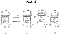
- FIG. 3 is an illustrative view showing schematically a mechanism of corrosion and wear of the cylinder bore when the compression ratio is fixed while the engine is in cold state.
- FIG. 3 (a)-(d) show situations at piston top dead center.
- FIG. 3 (a) relates to a cold state
- FIG. 3 (b)-(d) relate to a warmed-up state.
- FIG. 3 shows an internal combustion engine piston 71, a cylinder bore inner peripheral surface 72, a piston ring 73, a corroded portion 74 formed in cylinder bore inner peripheral surface 72, and a recess 75 formed in a place where piston ring 73 has shaved corroded portion 74.
- " ⁇ 8" indicates that the compression ratio is equal to 8
- " ⁇ 14" indicates that the compression ratio is equal to 14.
- the mechanical compression ratio of the internal combustion engine is controlled variably as shown by (b)-(d) in FIG. 3 . Since no condensed water occurs after completion of warming-up, even if variation of the mechanical compression ratio of the internal combustion engine causes piston ring 73 to shave the lower end of corroded portion 74, and thereby form recess 75, the non-corroded surface of recess 75 is not newly corroded.
- the mechanical compression ratio of internal combustion engine 1 is fixed. Specifically, it fixes the mechanical compression ratio of internal combustion engine 1 to the preset compression ratio point, in response to a condition that cooling water temperature Tw in water jacket 31a of cylinder block 31 is lower than preset temperature point Twth, wherein cooling water temperature Tw correlates with the cylinder bore wall temperature.
- Preset temperature point Twth is set higher than a point corresponding to a point of the cylinder bore wall temperature at which condensed water occurs on inner peripheral surface 32a of cylinder bore 32.
- preset temperature point Twth is set lower than a point corresponding to a point of the cylinder bore wall temperature at which no condensed water occurs on inner peripheral surface 32a of cylinder bore 32.
- preset temperature point Twth is set to the lowest point corresponding to the lowest point of the cylinder bore wall temperature at which no condensed water occurs on inner peripheral surface 32a of cylinder bore 32.
- the corroded portion of cylinder bore 32 is a portion of inner peripheral surface 32a of cylinder bore 32 on the cylinder head side (upper side) of first piston ring 35.
- the corroded portion of cylinder bore 32 is a portion of the bore surface on the upper side of the piston top ring.
- Corrosion of cylinder bore 32 is caused by acid formed from nitrogen oxides (NOx) contained in combustion gas and condensed water adhered to inner peripheral surface 32a of cylinder bore 32. While condensed water may occur, fixation of the mechanical compression ratio of internal combustion engine 1 to the preset compression ratio point serves to reliably delay the progress of corrosion.
- NOx nitrogen oxides
- the preset compression ratio point to which the mechanical compression ratio of internal combustion engine 1 is fixed when in cold state is set to an intermediate compression ratio point between a minimum compression ratio point and a maximum compression ratio point of a range of control such that the position of first piston ring 35 at the preset compression ratio point is set higher than the position of second piston ring 36 when the mechanical compression ratio is controlled to the maximum compression ratio point of the range of control.
- the minimum compression ratio point of the range of control is referred to simply as minimum compression ratio point
- the maximum compression ratio point of the range of control is referred to simply as maximum compression ratio point
- the intermediate compression ratio point between the minimum compression ratio point and the maximum compression ratio point of the range of control is referred to simply as intermediate compression ratio point.
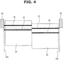
- FIG. 4 is an illustrative view showing a related part of the internal combustion engine according to the present invention, specifically showing a piston position when the mechanical compression ratio is at the maximum compression ratio point, and a piston position when the mechanical compression ratio is at the intermediate compression ratio point, in comparison.
- the left half of FIG. 4 shows a condition that the mechanical compression ratio is at the maximum compression ratio point
- the right half of FIG. 4 shows a condition that the mechanical compression ratio is at the intermediate compression ratio point.
- the setting that the preset compression ratio point is set to the intermediate compression ratio point, and the position of first piston ring 35 at the preset compression ratio point is set higher than the position of second piston ring 36 when the mechanical compression ratio is controlled to the maximum compression ratio point, serves to prevent second piston ring 36 from contacting a corroded portion 65 of cylinder bore 32, both at the piston position of top dead center under the maximum compression ratio point and at the piston position of top dead center under the preset compression ratio point.
- second piston ring 36 is reliably in contact with the non-corroded surface of cylinder bore 32, thereby ensuring the sealing.
- the corroded portion 65 is a portion of inner peripheral surface 32a of cylinder bore 32 which is corroded by acid formed from condensed water and nitrogen oxides (NOx) contained in combustion gas.
- the feature that the preset compression ratio point is different from the maximum compression ratio point, serves to allow relatively high load operation.
- the preset compression ratio point may be set to the maximum compression ratio point, instead of the intermediate compression ratio point.
- corroded portion 65 of inner peripheral surface 32a of cylinder bore 32 is maintained out of slide with first and second piston rings 35, 36, thus delaying the progress of corrosion due to wear of corroded portion 65 of inner peripheral surface 32a of cylinder bore 32.
- high load operation is limited by a requirement of knocking avoidance.
- the use of the sensed value of water temperature sensor 64 as the temperature correlating with the cylinder bore wall temperature allows application to the internal combustion engine provided with no sensor for directly sensing the temperature of inner peripheral surface 32a of cylinder bore 32.
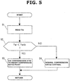
- FIG. 5 is a flow chart showing a flow of control according to the present embodiment.
- Step S1 it reads cooling water temperature Tw.
- Step S2 determines whether or not cooling water temperature Tw read at Step S1 is lower than preset temperature point Twth.
- Step S3 it determines whether or not cooling water temperature Tw read at Step S1 is lower than preset temperature point Twth.
- Step S3 it proceeds to Step S3.
- Step S4 it fixes the mechanical compression ratio of internal combustion engine 1 to the preset compression ratio point.
- Step S4 performs the normal compression ratio control to vary the mechanical compression ratio of internal combustion engine 1 variably in accordance with the operating condition.
Landscapes
- Engineering & Computer Science (AREA)
- Chemical & Material Sciences (AREA)
- Combustion & Propulsion (AREA)
- Mechanical Engineering (AREA)
- General Engineering & Computer Science (AREA)
- Output Control And Ontrol Of Special Type Engine (AREA)
Abstract
Description
- The present invention relates to a control device and a control method for an internal combustion engine structured to vary a compression ratio.
- A
patent document 1 discloses an internal combustion engine that includes: an in-cylinder-injection-use fuel injection valve for injecting fuel into a combustion chamber; a port-injection-use fuel injection valve for injecting fuel into an intake port; and a variable compression ratio mechanism structured to vary a mechanical compression ratio. - According to
patent document 1, when corrosion may occur in a tip end portion of a nozzle of the in-cylinder-injection-use fuel injection valve, the occurrence of corrosion is suppressed by increasing the mechanical compression ratio of the internal combustion engine, and allocating an entire quantity of fuel injection to port injection from the port-injection-use fuel injection valve. - However,
patent document 1 merely addresses suppression of the occurrence of corrosion in the tip end portion of the in-cylinder-injection-use fuel injection valve. - For example, when a temperature of cooling water of the internal combustion engine is low, adhesion of condensed water on an inner peripheral surface of a cylinder bore may cause corrosion in the inner peripheral surface of the cylinder bore by acid formed from condensed water and nitrogen oxides (NOx) contained in combustion gas.
- If the mechanical compression ratio of the internal combustion engine is controlled variably under a condition that condensed water adheres to the inner peripheral surface of the cylinder bore, a piston ring slides on a corroded portion of the cylinder bore, and thereby causes a corroded piece to fall off the corroded portion. When the mechanical compression ratio becomes low, a part which the corroded piece falls off may be newly corroded so that corrosion of the cylinder bore may progress.
- Namely, there is room for improvement in delaying the progress of corrosion which may occur in the internal combustion engine structured to vary the mechanical compression ratio.
- Patent Document 1: Japanese Patent Application Publication No.
2016-113945 - For an internal combustion engine structured to vary a mechanical compression ratio by varying a range of slide of a piston with respect to a cylinder bore, the present invention includes: acquiring a temperature correlating with a cylinder bore wall temperature; and fixing the mechanical compression ratio to a preset compression ratio point, in response to a condition that the acquired temperature is lower than a preset temperature point.
- According to the present invention, by fixing the mechanical compression ratio while the cylinder bore wall temperature is low, it is possible to prevent a piston ring from sliding on a corroded surface of the cylinder bore, and thereby delay the progress of corrosion.
-
-
FIG. 1 is an illustrative view showing schematic configuration of a control device of an internal combustion engine according to the present invention. -
FIG. 2 is an illustrative view showing schematically a mechanism of corrosion and wear of a cylinder bore when a compression ratio is varied in cold state. -
FIG. 3 is an illustrative view showing schematically a mechanism of corrosion and wear of a cylinder bore when a compression ratio is constant in cold state. -
FIG. 4 is an illustrative view showing a related part of the internal combustion engine according to the present invention. -
FIG. 5 is a flow chart showing a flow of control of the internal combustion engine according to the present invention. - The following describes an embodiment of the present invention in detail with reference to the drawings.
-
FIG. 1 is an illustrative view showing schematic configuration of a control device of aninternal combustion engine 1 according to the present invention, to which a control method ofinternal combustion engine 1 according to the present invention is applicable. -
Internal combustion engine 1 is mounted as a drive source on a vehicle such as an automotive vehicle, including anintake passage 2 and anexhaust passage 3.Intake passage 2 is connected to acombustion chamber 5 via an intake valve 4.Exhaust passage 3 is connected tocombustion chamber 5 via an exhaust valve 6. -
Internal combustion engine 1 includes a firstfuel injection valve 7 and a second fuel injection valve 8. Firstfuel injection valve 7 injects fuel directly intocombustion chamber 5. Second fuel injection valve 8 injects fuel intointake passage 2 upstream of intake valve 4. The fuel injected by firstfuel injection valve 7 and second fuel injection valve 8 is ignited incombustion chamber 5 by a spark plug 9. -
Intake passage 2 is provided with anair cleaner 10, anair flow meter 11, and athrottle valve 13.Air cleaner 10 collects foreign matter in intake air.Air flow meter 11 measures a quantity of intake air.Throttle valve 13 is an electronic throttle valve whose opening is controlled in accordance with a control signal from acontrol unit 12. -
Air flow meter 11 is disposed upstream ofthrottle valve 13.Air flow meter 11 contains a temperature sensor, and is structured to measure a temperature of intake air at an intake air inlet.Air cleaner 10 is disposed upstream ofair flow meter 11. -
Exhaust passage 3 is provided with anupstream exhaust catalyst 14 such as a three-way catalyst, and adownstream exhaust catalyst 15 such as a NOx trap catalyst.Downstream exhaust catalyst 15 is disposed downstream ofupstream exhaust catalyst 14. -
Internal combustion engine 1 further includes aturbocharger 18. Turbocharger 18 includes acompressor 16 disposed inintake passage 2, and anexhaust turbine 17 disposed inexhaust passage 3, whereincompressor 16 andexhaust turbine 17 are arranged coaxially.Compressor 16 is disposed upstream ofthrottle valve 13, and downstream ofair flow meter 11. Exhaustturbine 17 is disposed upstream ofupstream exhaust catalyst 14. -
Intake passage 2 is connected to arecirculation passage 19.Recirculation passage 19 includes a first end connected to a section ofintake passage 2 upstream ofcompressor 16, and a second end connected to a section ofintake passage 2 downstream ofcompressor 16. -
Recirculation passage 19 is provided with arecirculation valve 20.Recirculation valve 20 is an electronic recirculation valve structured to relieve a boost pressure from the section downstream ofcompressor 16 to the section upstream ofcompressor 16.Recirculation valve 20 may be implemented by a so-called check valve structured to open only when pressure downstream ofcompressor 16 becomes higher than or equal to a preset pressure point. -
Intake passage 2 is further provided with anintercooler 21. Intercooler 21 is disposed downstream ofcompressor 16, and is structured to cool intake air that is compressed (pressurized) bycompressor 16, for improvement in charging efficiency. Intercooler 21 is disposed downstream of the downstream end ofrecirculation passage 19, and upstream ofthrottle valve 13. -
Exhaust passage 3 is connected to an exhaust bypass passage 22. Exhaust bypass passage 22 bypassesexhaust turbine 17, and connects a section upstream ofexhaust turbine 17 to a section downstream ofexhaust turbine 17. Exhaust bypass passage 22 includes a downstream end connected to a section ofexhaust passage 3 upstream ofupstream exhaust catalyst 14. Exhaust bypass passage 22 is provided with awastegate valve 23.Wastegate valve 23 is an electronic wastegate valve that controls a quantity of exhaust gas in exhaust bypass passage 22.Wastegate valve 23 is structured to bypass a part of exhaust gas, which is to be introduced toexhaust turbine 17, to the section downstream ofexhaust turbine 17, and thereby control the boost pressure ofinternal combustion engine 1. -
Internal combustion engine 1 further includes anEGR passage 24. EGRpassage 24 is branched fromexhaust passage 3 and connected tointake passage 2, and is structured to perform exhaust gas recirculation (EGR) that introduces (recirculates) a part of exhaust gas as EGR gas fromexhaust passage 3 intointake passage 2. EGRpassage 24 includes a first end connected to a section ofexhaust passage 3 betweenupstream exhaust catalyst 14 anddownstream exhaust catalyst 15, and a second end connected to a section ofintake passage 2 downstream ofair flow meter 11 and upstream ofcompressor 16. EGRpassage 24 is provided with anEGR valve 25 and anEGR cooler 26.EGR valve 25 is an electronic EGR valve that controls a flow rate of EGR gas inEGR passage 24. EGRcooler 26 is structured to cool EGR gas. As shown inFIG. 1 ,intake passage 2 includes acollector section 27. -
Internal combustion engine 1 further includes a variable compression ratio mechanism 34 that is structured to vary a mechanical compression ratio ofinternal combustion engine 1 by varying a top dead center position of apiston 33 that slides in a cylinder bore 32 of acylinder block 31. Namely,internal combustion engine 1 is structured to vary the mechanical compression ratio by varying a range of slide ofpiston 33 with respect to an innerperipheral surface 32a of cylinder bore 32. In other words,internal combustion engine 1 is structured to vary the mechanical compression ratio by varying a range of slide ofpiston 33 with respect to the cylinder. The mechanical compression ratio is determined by the top dead center position and bottom dead center position ofpiston 33. -
Piston 33 includes afirst piston ring 35 and asecond piston ring 36, whereinfirst piston ring 35 is closer to a piston crown ofpiston 33 thansecond piston ring 36. Each offirst piston ring 35 andsecond piston ring 36 is a so-called compression ring, and serves to eliminate a clearance between innerperipheral surface 32a of cylinder bore 32 andpiston 33, and thereby maintain hermeticity. - Variable compression ratio mechanism 34 employs a multilink piston-crank mechanism in which
piston 33 is linked with acrank pin 38 of acrankshaft 37 via a plurality of links. Variable compression ratio mechanism 34 includes a lower link 39, anupper link 40, acontrol shaft 41, and acontrol link 42. Lower link 39 is rotatably attached to crankpin 38.Upper link 40 links lower link 39 withpiston 33.Control shaft 41 includes aneccentric shaft part 41a. Control link 42 linkseccentric shaft part 41a ofcontrol shaft 41 with lower link 39. -
Crankshaft 37 includesjournals 43 and crank pins 38.Journal 43 is rotatably supported betweencylinder block 31 and acrankshaft bearing bracket 44. -
Upper link 40 includes a first end rotatably attached to apiston pin 45, and a second end rotatably linked with lower link 39 via afirst connection pin 46.Control link 42 includes a first end rotatably linked with lower link 39 via a second connection pin 47, and a second end rotatably attached toeccentric shaft part 41a ofcontrol shaft 41.First connection pin 46 and second connection pin 47 are pressed into and fixed to lower link 39. -
Control shaft 41 is arranged in parallel tocrankshaft 37, and is rotatably supported bycylinder block 31. Specifically,control shaft 41 is rotatably supported betweencrankshaft bearing bracket 44 and a controlshaft bearing bracket 48. -
Cylinder block 31 includes a lower part to which an oil panupper part 49 is attached. Oil panupper part 49 includes a lower part to which an oil panlower part 50 is attached. -
Control shaft 41 receives input of rotation of adrive shaft 53 that is transmitted via anactuator link 51 and adrive shaft arm 52. Driveshaft 53 is disposed outside of oil panupper part 49, and is arranged parallel to controlshaft 41. Driveshaft arm 52 is fixed to driveshaft 53. -
Actuator link 51 includes a first end rotatably linked withdrive shaft arm 52 via apin 54a.Actuator link 51 is a narrow rod-shaped member that is arranged to be perpendicular to controlshaft 41, and includes a second end rotatably linked via apin 54b with a portion ofcontrol shaft 41 eccentric from a rotation center ofcontrol shaft 41. - Drive
shaft 53,drive shaft arm 52, and the first end portion ofactuator link 51 are mounted in ahousing 55 that is attached to a side face of oil panupper part 49. - Drive
shaft 53 includes a first end connected to anelectric motor 56 as an actuator via a speed reducer not shown. Namely, driveshaft 53 is rotationally driven byelectric motor 56. The rotation speed ofdrive shaft 53 results from reduction from the rotation speed ofelectric motor 56 by the speed reducer. - As
drive shaft 53 is rotated byelectric motor 56,actuator link 51 travels along a plane perpendicular to driveshaft 53. The travel of actuator link 51 causes a swinging motion of the place of linkage between the second end ofactuator link 51 andcontrol shaft 41, and thereby rotatescontrol shaft 41. Ascontrol shaft 41 rotates and varies its rotational position,eccentric shaft part 41a varies its position, whereineccentric shaft part 41a serves as a fulcrum of swinging motion ofcontrol link 42. In this way, by variation of the rotational position ofcontrol shaft 41 byelectric motor 56, the attitude of lower link 39 varies, to cause a variation in piston motion (stroke characteristics) ofpiston 33, namely, a variation in the top dead center position and bottom dead center position ofpiston 33, so that the mechanical compression ratio ofinternal combustion engine 1 is continuously varied. - The mechanical compression ratio of
internal combustion engine 1 is normally controlled by a normal compression ratio control based on an operating condition of internal combustion engine 1 (engine operating condition). The normal compression ratio control may be implemented by setting the mechanical compression ratio such that the mechanical compression ratio decreases as the operating condition ofinternal combustion engine 1 increases in speed and load. - Rotation of
electric motor 56 is controlled bycontrol unit 12. Namely,control unit 12 serves as a compression ratio control section to vary and fix the mechanical compression ratio ofinternal combustion engine 1 by variable compression ratio mechanism 34. -
Control unit 12 is a publicly known digital computer that contains a CPU, a ROM, a RAM, and input/output interfaces. -
Control unit 12 receives input of sensing signals from various sensors, namely,air flow meter 11, a crank angle sensor 61 for sensing a crank angle ofcrankshaft 37, an accelerator opening sensor 62 for sensing an amount of depression of an accelerator pedal, arotation angle sensor 63 for sensing a rotation angle ofdrive shaft 53, awater temperature sensor 64 for sensing a cooling water temperature Tw, etc.Control unit 12 calculates a requested load of the internal combustion engine (i.e. engine load), based on a sensing value of accelerator opening sensor 62. - Crank angle sensor 61 is structured to measure the engine speed of
internal combustion engine 1. -
Water temperature sensor 64 serves as a wall temperature acquiring section to acquire a temperature of cooling water flowing around cylinder bore 32, as a temperature correlating with a cylinder bore wall temperature. In other words,water temperature sensor 64 acquires a temperature of cooling water flowing around the inner peripheral surface of the cylinder, as a temperature correlating with the cylinder bore wall temperature. The cylinder bore wall temperature is a wall temperature of innerperipheral surface 32a of cylinder bore 32. In other words, the cylinder bore wall temperature is a wall temperature of the inner peripheral surface of the cylinder. In the present embodiment,water temperature sensor 64 measures a temperature of cooling water in awater jacket 31a ofcylinder block 31. - Based on the sensing signals from the various sensors,
control unit 12 optimally controls the fuel injection quantity and fuel injection timing of each of firstfuel injection valve 7 and second fuel injection valve 8, the ignition timing of spark plug 9, the opening ofthrottle valve 13, the opening ofrecirculation valve 20, the opening ofwastegate valve 23, the opening ofEGR valve 25, the mechanical compression ratio ofinternal combustion engine 1 set by variable compression ratio mechanism 34, etc. - When cooling water temperature Tw of
internal combustion engine 1 is low, the cylinder bore wall temperature is also low. In such a condition of low water temperature, condensed water may occur incombustion chamber 5. If condensed water occurs and adheres to innerperipheral surface 32a of cylinder bore 32, the condensed water is mixed with nitrogen oxides (NOx) contained in combustion gas to form acid which may corrode the inner peripheral surface of the cylinder bore on the upper side of the position of the piston ring at top dead center. On the other hand, even with acid formed from condensed water and nitrogen oxides, there is no possibility that the inner peripheral surface of the cylinder bore on the upper side of the position of the piston ring at top dead center is corroded, because the acid is swept away upward. - In general, in an internal combustion engine structured to vary a mechanical compression ratio, as a top dead center position is varied, a piston ring slides on a corroded portion of an inner peripheral surface of a cylinder bore. Accordingly, as shown in
FIG. 2 , corrosion of the inner peripheral surface of the cylinder bore may progress due to repetition of a process that the slide of the piston ring wears the corroded portion, and the part from which a corroded piece is removed is newly corroded. -
FIG. 2 is an illustrative view showing schematically a mechanism of corrosion and wear of the cylinder bore when the compression ratio is varied while the engine is in cold state. InFIG. 2, (a)-(f) represent situations at piston top dead center. -
FIG. 2 shows an internalcombustion engine piston 71, a cylinder bore innerperipheral surface 72, apiston ring 73, a corrodedportion 74 formed in cylinder bore innerperipheral surface 72, and arecess 75 formed in a place wherepiston ring 73 has shaved corrodedportion 74. InFIG. 2 , "ε8" indicates that the compression ratio is equal to 8, and "ε14" indicates that the compression ratio is equal to 14. - As shown by (a)-(c) in
FIG. 2 , as the mechanical compression ratio of the internal combustion engine varies from a lower point (ε8) to a higher point (ε14), the piston top dead center position moves upward, andpiston ring 73 shaves a lower end of corrodedportion 74, thereby forming therecess 75 in cylinder bore innerperipheral surface 72.Recess 75 is formed after corrodedportion 74 is shaved, and includes a surface not corroded (non-corroded surface). In (a)-(c) inFIG. 2 ,recess 75 is located radially outside ofpiston ring 73 located at the piston top dead center position when the mechanical compression ratio is high. - Then, as the mechanical compression ratio of the internal combustion engine is varied to the lower point (ε8) from the state of (c) in
FIG. 2 , the piston top dead center position moves downward. Accordingly, as shown by (d) inFIG. 2 , the non-corroded surface ofrecess 75 is newly corroded by acid formed from condensed water and nitrogen oxides (NOx) contained in combustion gas. - Then, as the mechanical compression ratio of the internal combustion engine is varied to the higher point (ε14) from the state of (d) in
FIG. 2 , the piston top dead center position moves upward. Accordingly, as shown by (e) inFIG. 2 , a newly corroded portion ofrecess 75 is shaved bypiston ring 73, so thatrecess 75 becomes large. - Then, as the mechanical compression ratio of the internal combustion engine is varied to the lower point (ε8) from the state of (e) in
FIG. 2 , the piston top dead center position moves downward. Accordingly, as shown by (f) inFIG. 2 , the non-corroded surface ofrecess 75 is newly corroded by acid formed from condensed water and nitrogen oxides (NOx) contained in combustion gas. - In this way, if the mechanical compression ratio of the internal combustion engine is controlled variably under condition that the occurrence of condensed water is possible, each variation of the mechanical compression ratio causes corrosion of cylinder bore inner
peripheral surface 72 to progress. -
FIG. 3 is an illustrative view showing schematically a mechanism of corrosion and wear of the cylinder bore when the compression ratio is fixed while the engine is in cold state.FIG. 3 (a)-(d) show situations at piston top dead center.FIG. 3 (a) relates to a cold state, andFIG. 3 (b)-(d) relate to a warmed-up state. -
FIG. 3 shows an internalcombustion engine piston 71, a cylinder bore innerperipheral surface 72, apiston ring 73, a corrodedportion 74 formed in cylinder bore innerperipheral surface 72, and arecess 75 formed in a place wherepiston ring 73 has shaved corrodedportion 74. InFIG. 2 , "ε8" indicates that the compression ratio is equal to 8, and "ε14" indicates that the compression ratio is equal to 14. - As shown by (a) in
FIG. 3 , when the mechanical compression ratio of the internal combustion engine is fixed to a preset compression ratio point such as ε8 under condition that the internal combustion engine is in cold state,piston ring 73 does not slide on corrodedportion 74 formed in cylinder bore innerperipheral surface 72 on the upper side of the position ofpiston ring 73 at top dead center. Accordingly, corrosion of cylinder bore innerperipheral surface 72 does not progress while the engine is in cold state. - After completion of warming-up of the internal combustion engine, the mechanical compression ratio of the internal combustion engine is controlled variably as shown by (b)-(d) in
FIG. 3 . Since no condensed water occurs after completion of warming-up, even if variation of the mechanical compression ratio of the internal combustion engine causespiston ring 73 to shave the lower end of corrodedportion 74, and thereby formrecess 75, the non-corroded surface ofrecess 75 is not newly corroded. - From this viewpoint, according to the present embodiment, while the wall temperature of inner
peripheral surface 32a of cylinder bore 32 is low, the mechanical compression ratio ofinternal combustion engine 1 is fixed. Specifically, it fixes the mechanical compression ratio ofinternal combustion engine 1 to the preset compression ratio point, in response to a condition that cooling water temperature Tw inwater jacket 31a ofcylinder block 31 is lower than preset temperature point Twth, wherein cooling water temperature Tw correlates with the cylinder bore wall temperature. - Preset temperature point Twth is set higher than a point corresponding to a point of the cylinder bore wall temperature at which condensed water occurs on inner
peripheral surface 32a of cylinder bore 32. In other words, preset temperature point Twth is set lower than a point corresponding to a point of the cylinder bore wall temperature at which no condensed water occurs on innerperipheral surface 32a of cylinder bore 32. For example, preset temperature point Twth is set to the lowest point corresponding to the lowest point of the cylinder bore wall temperature at which no condensed water occurs on innerperipheral surface 32a of cylinder bore 32. - This prevents
first piston ring 35 from sliding on a corroded portion of cylinder bore 32, and thereby serves to delay the progress of corrosion. The corroded portion of cylinder bore 32 is a portion of innerperipheral surface 32a of cylinder bore 32 on the cylinder head side (upper side) offirst piston ring 35. In other words, the corroded portion of cylinder bore 32 is a portion of the bore surface on the upper side of the piston top ring. - Corrosion of cylinder bore 32 is caused by acid formed from nitrogen oxides (NOx) contained in combustion gas and condensed water adhered to inner
peripheral surface 32a of cylinder bore 32. While condensed water may occur, fixation of the mechanical compression ratio ofinternal combustion engine 1 to the preset compression ratio point serves to reliably delay the progress of corrosion. - The preset compression ratio point to which the mechanical compression ratio of
internal combustion engine 1 is fixed when in cold state is set to an intermediate compression ratio point between a minimum compression ratio point and a maximum compression ratio point of a range of control such that the position offirst piston ring 35 at the preset compression ratio point is set higher than the position ofsecond piston ring 36 when the mechanical compression ratio is controlled to the maximum compression ratio point of the range of control. For convenience of explanation in the following description, the minimum compression ratio point of the range of control is referred to simply as minimum compression ratio point, and the maximum compression ratio point of the range of control is referred to simply as maximum compression ratio point, and the intermediate compression ratio point between the minimum compression ratio point and the maximum compression ratio point of the range of control is referred to simply as intermediate compression ratio point. -
FIG. 4 is an illustrative view showing a related part of the internal combustion engine according to the present invention, specifically showing a piston position when the mechanical compression ratio is at the maximum compression ratio point, and a piston position when the mechanical compression ratio is at the intermediate compression ratio point, in comparison. Specifically, the left half ofFIG. 4 shows a condition that the mechanical compression ratio is at the maximum compression ratio point, and the right half ofFIG. 4 shows a condition that the mechanical compression ratio is at the intermediate compression ratio point. - As shown in
FIG. 4 , the setting that the preset compression ratio point is set to the intermediate compression ratio point, and the position offirst piston ring 35 at the preset compression ratio point is set higher than the position ofsecond piston ring 36 when the mechanical compression ratio is controlled to the maximum compression ratio point, serves to preventsecond piston ring 36 from contacting a corrodedportion 65 of cylinder bore 32, both at the piston position of top dead center under the maximum compression ratio point and at the piston position of top dead center under the preset compression ratio point. - When the control to vary the mechanical compression ratio is permitted to set the mechanical compression ratio to the maximum compression ratio point,
second piston ring 36 is reliably in contact with the non-corroded surface of cylinder bore 32, thereby ensuring the sealing. - The corroded
portion 65 is a portion of innerperipheral surface 32a of cylinder bore 32 which is corroded by acid formed from condensed water and nitrogen oxides (NOx) contained in combustion gas. - The feature that the preset compression ratio point is different from the maximum compression ratio point, serves to allow relatively high load operation.
- The preset compression ratio point may be set to the maximum compression ratio point, instead of the intermediate compression ratio point. In this case, corroded
portion 65 of innerperipheral surface 32a of cylinder bore 32 is maintained out of slide with first and second piston rings 35, 36, thus delaying the progress of corrosion due to wear of corrodedportion 65 of innerperipheral surface 32a of cylinder bore 32. However, in case of the setting of the preset compression ratio point to the maximum compression ratio point, high load operation is limited by a requirement of knocking avoidance. - Since the cylinder bore wall temperature correlates significantly with the temperature of cooling water flowing around cylinder bore 32, the use of the sensed value of
water temperature sensor 64 as the temperature correlating with the cylinder bore wall temperature allows application to the internal combustion engine provided with no sensor for directly sensing the temperature of innerperipheral surface 32a of cylinder bore 32. - When cooling water temperature Tw becomes higher than or equal to preset temperature point Twth, the fixation of the compression ratio of variable compression ratio mechanism 34 to the preset compression ratio point is terminated, and the normal compression ratio control is started.
- In this way, when the condition that no corrosion occurs (the condition that no condensed water occurs) is established, it is possible to quickly shift into the normal compression ratio control.
-
FIG. 5 is a flow chart showing a flow of control according to the present embodiment. - At Step S1, it reads cooling water temperature Tw. At Step S2, it determines whether or not cooling water temperature Tw read at Step S1 is lower than preset temperature point Twth. When determining at Step S2 that cooling water temperature Tw is lower than preset temperature point Twth, it proceeds to Step S3. When determining at Step S2 that cooling water temperature Tw is higher than or equal to preset temperature point Twth, it proceeds to Step S4. At Step S3, it fixes the mechanical compression ratio of
internal combustion engine 1 to the preset compression ratio point. At Step S4, it performs the normal compression ratio control to vary the mechanical compression ratio ofinternal combustion engine 1 variably in accordance with the operating condition.
Claims (7)
- A control method for an internal combustion engine structured to vary a mechanical compression ratio by varying a range of slide of a piston with respect to a cylinder bore, the control method comprising:acquiring a temperature correlating with a cylinder bore wall temperature; andfixing the mechanical compression ratio to a preset compression ratio point, in response to a condition that the acquired temperature is lower than a preset temperature point.
- The control method as claimed in Claim 1, comprising:
setting the preset temperature point higher than a point corresponding to a point of the cylinder bore wall temperature at which condensed water occurs in the cylinder bore. - The control method as claimed in Claim 1 or 2, wherein the piston includes a piston crown, a first piston ring, and a second piston ring, and wherein the first piston ring is closer to the piston crown than the second piston ring, the control method comprising:
setting the preset compression ratio point to an intermediate compression ratio point between a minimum compression ratio point and a maximum compression ratio point of a range of control, wherein the first piston ring is higher in position when the mechanical compression ratio is at the preset compression ratio point than the second piston ring when the mechanical compression ratio is controlled to the maximum compression ratio point. - The control method as claimed in Claim 1 or 2, comprising:
setting the preset compression ratio point to the maximum compression ratio point of the range of control. - The control method as claimed in any one of Claims 1 to 4, comprising:
acquiring a temperature of cooling water flowing around the cylinder bore as the temperature correlating with the cylinder bore wall temperature. - The control method as claimed in any one of Claims 1 to 5, comprising:
performing a variable compression ratio control based on an engine operating condition, in response to a condition that the acquired temperature correlating with the cylinder bore wall temperature becomes higher than or equal to the preset temperature point. - A control device for an internal combustion engine structured to vary a mechanical compression ratio by varying a range of slide of a piston with respect to a cylinder bore, the control device comprising:a wall temperature acquiring section structured to acquire a temperature correlating with a cylinder bore wall temperature; anda compression ratio control section configured to fix the mechanical compression ratio to a preset compression ratio point, in response to a condition that the acquired temperature is lower than a preset temperature point.
Applications Claiming Priority (1)
| Application Number | Priority Date | Filing Date | Title |
|---|---|---|---|
| PCT/JP2017/017109 WO2018203360A1 (en) | 2017-05-01 | 2017-05-01 | Control method for internal combustion engine and control device for internal combustion engine |
Publications (3)
| Publication Number | Publication Date |
|---|---|
| EP3620637A1 true EP3620637A1 (en) | 2020-03-11 |
| EP3620637A4 EP3620637A4 (en) | 2020-04-22 |
| EP3620637B1 EP3620637B1 (en) | 2021-03-10 |
Family
ID=64017018
Family Applications (1)
| Application Number | Title | Priority Date | Filing Date |
|---|---|---|---|
| EP17908545.1A Active EP3620637B1 (en) | 2017-05-01 | 2017-05-01 | Control method for internal combustion engine and control device for internal combustion engine |
Country Status (5)
| Country | Link |
|---|---|
| US (1) | US10815879B2 (en) |
| EP (1) | EP3620637B1 (en) |
| JP (1) | JP6721119B2 (en) |
| CN (1) | CN110621860B (en) |
| WO (1) | WO2018203360A1 (en) |
Family Cites Families (15)
| Publication number | Priority date | Publication date | Assignee | Title |
|---|---|---|---|---|
| JP2005069131A (en) * | 2003-08-26 | 2005-03-17 | Nissan Motor Co Ltd | Control device for internal combustion engine with variable compression ratio mechanism |
| JP2007146701A (en) | 2005-11-25 | 2007-06-14 | Toyota Motor Corp | Internal combustion engine with variable compression ratio |
| JP5082938B2 (en) | 2008-03-07 | 2012-11-28 | トヨタ自動車株式会社 | Spark ignition internal combustion engine |
| JP2009293496A (en) | 2008-06-04 | 2009-12-17 | Toyota Motor Corp | Variable compression ratio internal combustion engine |
| US8511279B2 (en) * | 2009-01-06 | 2013-08-20 | Toyota Jidosha Kabushiki Kaisha | Spark ignition type internal combustion engine |
| WO2011027478A1 (en) * | 2009-09-03 | 2011-03-10 | トヨタ自動車株式会社 | Variable-compression-ratio, v-type internal combustion engine |
| JP5459503B2 (en) | 2010-07-14 | 2014-04-02 | 株式会社Ihi | Diesel engine cylinder bore corrosion prevention system |
| JP5906591B2 (en) | 2011-06-17 | 2016-04-20 | 日産自動車株式会社 | Control device for variable compression ratio internal combustion engine |
| JP5854126B2 (en) * | 2012-03-22 | 2016-02-09 | トヨタ自動車株式会社 | Control device for internal combustion engine |
| WO2014119354A1 (en) | 2013-02-01 | 2014-08-07 | 日産自動車株式会社 | Control device and control method for internal combustion engine |
| WO2014141729A1 (en) | 2013-03-13 | 2014-09-18 | 日産自動車株式会社 | Device and method for controlling internal combustion engine |
| JP5790684B2 (en) * | 2013-03-22 | 2015-10-07 | トヨタ自動車株式会社 | Spark ignition internal combustion engine |
| JP6413733B2 (en) | 2014-12-15 | 2018-10-31 | 日産自動車株式会社 | Control device for internal combustion engine |
| JP6697374B2 (en) * | 2016-12-19 | 2020-05-20 | 日立オートモティブシステムズ株式会社 | Internal combustion engine control device and combustion chamber wall temperature estimation method |
| JP6583313B2 (en) * | 2017-02-28 | 2019-10-02 | トヨタ自動車株式会社 | Control device for internal combustion engine |
-
2017
- 2017-05-01 JP JP2019516301A patent/JP6721119B2/en active Active
- 2017-05-01 EP EP17908545.1A patent/EP3620637B1/en active Active
- 2017-05-01 WO PCT/JP2017/017109 patent/WO2018203360A1/en not_active Ceased
- 2017-05-01 US US16/609,323 patent/US10815879B2/en active Active
- 2017-05-01 CN CN201780090232.2A patent/CN110621860B/en active Active
Also Published As
| Publication number | Publication date |
|---|---|
| JP6721119B2 (en) | 2020-07-08 |
| WO2018203360A1 (en) | 2018-11-08 |
| US10815879B2 (en) | 2020-10-27 |
| CN110621860B (en) | 2020-10-27 |
| JPWO2018203360A1 (en) | 2019-11-07 |
| EP3620637B1 (en) | 2021-03-10 |
| EP3620637A4 (en) | 2020-04-22 |
| CN110621860A (en) | 2019-12-27 |
| US20200056537A1 (en) | 2020-02-20 |
Similar Documents
| Publication | Publication Date | Title |
|---|---|---|
| US10920629B2 (en) | Oil temperature sensor diagnostic device | |
| Watanabe et al. | Research on extended expansion general-purpose engine theoretical analysis of multiple linkage system and improvement of thermal efficiency | |
| JP4793408B2 (en) | Intake control device for internal combustion engine and automatic adaptation device for internal combustion engine | |
| US9784190B2 (en) | Internal combustion engine control device and control method | |
| US10815879B2 (en) | Control method for internal combustion engine and control device for internal combustion engine | |
| US10927772B2 (en) | Control method for internal combustion engine, and control system for internal combustion engine | |
| EP3620626B1 (en) | Control method for internal combustion engine and control device for internal combustion engine | |
| JP2009013849A (en) | Diesel engine control device | |
| JP2005069131A (en) | Control device for internal combustion engine with variable compression ratio mechanism | |
| US11215137B1 (en) | Engine device | |
| JP7700745B2 (en) | Control device for internal combustion engine | |
| US12535021B2 (en) | Internal combustion engine control device and internal combustion engine control method | |
| US11067023B2 (en) | Internal combustion engine diagnostic method and internal combustion engine diagnostic device | |
| CN113853479B (en) | Control method and control device of internal combustion engine | |
| JP2009275679A (en) | Intake-air controller for internal combustion engine, and automatic adapting device for internal combustion engine | |
| WO2025126365A1 (en) | Control device for internal combustion engine | |
| JP2026037677A (en) | Gas sensor abnormality diagnosis device | |
| WO2019043902A1 (en) | Torque estimation method for internal combustion engine, and torque estimation device for internal combustion engine |
Legal Events
| Date | Code | Title | Description |
|---|---|---|---|
| STAA | Information on the status of an ep patent application or granted ep patent |
Free format text: STATUS: THE INTERNATIONAL PUBLICATION HAS BEEN MADE |
|
| PUAI | Public reference made under article 153(3) epc to a published international application that has entered the european phase |
Free format text: ORIGINAL CODE: 0009012 |
|
| STAA | Information on the status of an ep patent application or granted ep patent |
Free format text: STATUS: REQUEST FOR EXAMINATION WAS MADE |
|
| 17P | Request for examination filed |
Effective date: 20191113 |
|
| AK | Designated contracting states |
Kind code of ref document: A1 Designated state(s): AL AT BE BG CH CY CZ DE DK EE ES FI FR GB GR HR HU IE IS IT LI LT LU LV MC MK MT NL NO PL PT RO RS SE SI SK SM TR |
|
| AX | Request for extension of the european patent |
Extension state: BA ME |
|
| REG | Reference to a national code |
Ref country code: DE Ref legal event code: R079 Ref document number: 602017034579 Country of ref document: DE Free format text: PREVIOUS MAIN CLASS: F02D0015040000 Ipc: F02D0015020000 |
|
| A4 | Supplementary search report drawn up and despatched |
Effective date: 20200325 |
|
| RIC1 | Information provided on ipc code assigned before grant |
Ipc: F02D 41/06 20060101ALI20200319BHEP Ipc: F02D 15/02 20060101AFI20200319BHEP Ipc: F02B 75/04 20060101ALI20200319BHEP Ipc: F02D 35/02 20060101ALI20200319BHEP |
|
| DAV | Request for validation of the european patent (deleted) | ||
| DAX | Request for extension of the european patent (deleted) | ||
| GRAP | Despatch of communication of intention to grant a patent |
Free format text: ORIGINAL CODE: EPIDOSNIGR1 |
|
| STAA | Information on the status of an ep patent application or granted ep patent |
Free format text: STATUS: GRANT OF PATENT IS INTENDED |
|
| INTG | Intention to grant announced |
Effective date: 20201103 |
|
| GRAS | Grant fee paid |
Free format text: ORIGINAL CODE: EPIDOSNIGR3 |
|
| GRAA | (expected) grant |
Free format text: ORIGINAL CODE: 0009210 |
|
| STAA | Information on the status of an ep patent application or granted ep patent |
Free format text: STATUS: THE PATENT HAS BEEN GRANTED |
|
| AK | Designated contracting states |
Kind code of ref document: B1 Designated state(s): AL AT BE BG CH CY CZ DE DK EE ES FI FR GB GR HR HU IE IS IT LI LT LU LV MC MK MT NL NO PL PT RO RS SE SI SK SM TR |
|
| REG | Reference to a national code |
Ref country code: GB Ref legal event code: FG4D |
|
| REG | Reference to a national code |
Ref country code: AT Ref legal event code: REF Ref document number: 1370040 Country of ref document: AT Kind code of ref document: T Effective date: 20210315 Ref country code: CH Ref legal event code: EP |
|
| REG | Reference to a national code |
Ref country code: IE Ref legal event code: FG4D |
|
| REG | Reference to a national code |
Ref country code: DE Ref legal event code: R096 Ref document number: 602017034579 Country of ref document: DE |
|
| REG | Reference to a national code |
Ref country code: LT Ref legal event code: MG9D |
|
| PG25 | Lapsed in a contracting state [announced via postgrant information from national office to epo] |
Ref country code: BG Free format text: LAPSE BECAUSE OF FAILURE TO SUBMIT A TRANSLATION OF THE DESCRIPTION OR TO PAY THE FEE WITHIN THE PRESCRIBED TIME-LIMIT Effective date: 20210610 Ref country code: LT Free format text: LAPSE BECAUSE OF FAILURE TO SUBMIT A TRANSLATION OF THE DESCRIPTION OR TO PAY THE FEE WITHIN THE PRESCRIBED TIME-LIMIT Effective date: 20210310 Ref country code: NO Free format text: LAPSE BECAUSE OF FAILURE TO SUBMIT A TRANSLATION OF THE DESCRIPTION OR TO PAY THE FEE WITHIN THE PRESCRIBED TIME-LIMIT Effective date: 20210610 Ref country code: HR Free format text: LAPSE BECAUSE OF FAILURE TO SUBMIT A TRANSLATION OF THE DESCRIPTION OR TO PAY THE FEE WITHIN THE PRESCRIBED TIME-LIMIT Effective date: 20210310 Ref country code: GR Free format text: LAPSE BECAUSE OF FAILURE TO SUBMIT A TRANSLATION OF THE DESCRIPTION OR TO PAY THE FEE WITHIN THE PRESCRIBED TIME-LIMIT Effective date: 20210611 Ref country code: FI Free format text: LAPSE BECAUSE OF FAILURE TO SUBMIT A TRANSLATION OF THE DESCRIPTION OR TO PAY THE FEE WITHIN THE PRESCRIBED TIME-LIMIT Effective date: 20210310 |
|
| REG | Reference to a national code |
Ref country code: AT Ref legal event code: MK05 Ref document number: 1370040 Country of ref document: AT Kind code of ref document: T Effective date: 20210310 |
|
| REG | Reference to a national code |
Ref country code: NL Ref legal event code: MP Effective date: 20210310 |
|
| PG25 | Lapsed in a contracting state [announced via postgrant information from national office to epo] |
Ref country code: RS Free format text: LAPSE BECAUSE OF FAILURE TO SUBMIT A TRANSLATION OF THE DESCRIPTION OR TO PAY THE FEE WITHIN THE PRESCRIBED TIME-LIMIT Effective date: 20210310 Ref country code: LV Free format text: LAPSE BECAUSE OF FAILURE TO SUBMIT A TRANSLATION OF THE DESCRIPTION OR TO PAY THE FEE WITHIN THE PRESCRIBED TIME-LIMIT Effective date: 20210310 Ref country code: SE Free format text: LAPSE BECAUSE OF FAILURE TO SUBMIT A TRANSLATION OF THE DESCRIPTION OR TO PAY THE FEE WITHIN THE PRESCRIBED TIME-LIMIT Effective date: 20210310 |
|
| PG25 | Lapsed in a contracting state [announced via postgrant information from national office to epo] |
Ref country code: NL Free format text: LAPSE BECAUSE OF FAILURE TO SUBMIT A TRANSLATION OF THE DESCRIPTION OR TO PAY THE FEE WITHIN THE PRESCRIBED TIME-LIMIT Effective date: 20210310 |
|
| PG25 | Lapsed in a contracting state [announced via postgrant information from national office to epo] |
Ref country code: AT Free format text: LAPSE BECAUSE OF FAILURE TO SUBMIT A TRANSLATION OF THE DESCRIPTION OR TO PAY THE FEE WITHIN THE PRESCRIBED TIME-LIMIT Effective date: 20210310 Ref country code: SM Free format text: LAPSE BECAUSE OF FAILURE TO SUBMIT A TRANSLATION OF THE DESCRIPTION OR TO PAY THE FEE WITHIN THE PRESCRIBED TIME-LIMIT Effective date: 20210310 Ref country code: EE Free format text: LAPSE BECAUSE OF FAILURE TO SUBMIT A TRANSLATION OF THE DESCRIPTION OR TO PAY THE FEE WITHIN THE PRESCRIBED TIME-LIMIT Effective date: 20210310 Ref country code: CZ Free format text: LAPSE BECAUSE OF FAILURE TO SUBMIT A TRANSLATION OF THE DESCRIPTION OR TO PAY THE FEE WITHIN THE PRESCRIBED TIME-LIMIT Effective date: 20210310 |
|
| PG25 | Lapsed in a contracting state [announced via postgrant information from national office to epo] |
Ref country code: IS Free format text: LAPSE BECAUSE OF FAILURE TO SUBMIT A TRANSLATION OF THE DESCRIPTION OR TO PAY THE FEE WITHIN THE PRESCRIBED TIME-LIMIT Effective date: 20210710 Ref country code: SK Free format text: LAPSE BECAUSE OF FAILURE TO SUBMIT A TRANSLATION OF THE DESCRIPTION OR TO PAY THE FEE WITHIN THE PRESCRIBED TIME-LIMIT Effective date: 20210310 Ref country code: RO Free format text: LAPSE BECAUSE OF FAILURE TO SUBMIT A TRANSLATION OF THE DESCRIPTION OR TO PAY THE FEE WITHIN THE PRESCRIBED TIME-LIMIT Effective date: 20210310 Ref country code: PL Free format text: LAPSE BECAUSE OF FAILURE TO SUBMIT A TRANSLATION OF THE DESCRIPTION OR TO PAY THE FEE WITHIN THE PRESCRIBED TIME-LIMIT Effective date: 20210310 Ref country code: PT Free format text: LAPSE BECAUSE OF FAILURE TO SUBMIT A TRANSLATION OF THE DESCRIPTION OR TO PAY THE FEE WITHIN THE PRESCRIBED TIME-LIMIT Effective date: 20210712 |
|
| REG | Reference to a national code |
Ref country code: DE Ref legal event code: R097 Ref document number: 602017034579 Country of ref document: DE |
|
| REG | Reference to a national code |
Ref country code: CH Ref legal event code: PL |
|
| PLBE | No opposition filed within time limit |
Free format text: ORIGINAL CODE: 0009261 |
|
| STAA | Information on the status of an ep patent application or granted ep patent |
Free format text: STATUS: NO OPPOSITION FILED WITHIN TIME LIMIT |
|
| PG25 | Lapsed in a contracting state [announced via postgrant information from national office to epo] |
Ref country code: LI Free format text: LAPSE BECAUSE OF NON-PAYMENT OF DUE FEES Effective date: 20210531 Ref country code: LU Free format text: LAPSE BECAUSE OF NON-PAYMENT OF DUE FEES Effective date: 20210501 Ref country code: MC Free format text: LAPSE BECAUSE OF FAILURE TO SUBMIT A TRANSLATION OF THE DESCRIPTION OR TO PAY THE FEE WITHIN THE PRESCRIBED TIME-LIMIT Effective date: 20210310 Ref country code: DK Free format text: LAPSE BECAUSE OF FAILURE TO SUBMIT A TRANSLATION OF THE DESCRIPTION OR TO PAY THE FEE WITHIN THE PRESCRIBED TIME-LIMIT Effective date: 20210310 Ref country code: CH Free format text: LAPSE BECAUSE OF NON-PAYMENT OF DUE FEES Effective date: 20210531 Ref country code: AL Free format text: LAPSE BECAUSE OF FAILURE TO SUBMIT A TRANSLATION OF THE DESCRIPTION OR TO PAY THE FEE WITHIN THE PRESCRIBED TIME-LIMIT Effective date: 20210310 Ref country code: ES Free format text: LAPSE BECAUSE OF FAILURE TO SUBMIT A TRANSLATION OF THE DESCRIPTION OR TO PAY THE FEE WITHIN THE PRESCRIBED TIME-LIMIT Effective date: 20210310 |
|
| REG | Reference to a national code |
Ref country code: BE Ref legal event code: MM Effective date: 20210531 |
|
| 26N | No opposition filed |
Effective date: 20211213 |
|
| PG25 | Lapsed in a contracting state [announced via postgrant information from national office to epo] |
Ref country code: SI Free format text: LAPSE BECAUSE OF FAILURE TO SUBMIT A TRANSLATION OF THE DESCRIPTION OR TO PAY THE FEE WITHIN THE PRESCRIBED TIME-LIMIT Effective date: 20210310 |
|
| PG25 | Lapsed in a contracting state [announced via postgrant information from national office to epo] |
Ref country code: IT Free format text: LAPSE BECAUSE OF FAILURE TO SUBMIT A TRANSLATION OF THE DESCRIPTION OR TO PAY THE FEE WITHIN THE PRESCRIBED TIME-LIMIT Effective date: 20210310 Ref country code: IE Free format text: LAPSE BECAUSE OF NON-PAYMENT OF DUE FEES Effective date: 20210501 |
|
| PG25 | Lapsed in a contracting state [announced via postgrant information from national office to epo] |
Ref country code: IS Free format text: LAPSE BECAUSE OF FAILURE TO SUBMIT A TRANSLATION OF THE DESCRIPTION OR TO PAY THE FEE WITHIN THE PRESCRIBED TIME-LIMIT Effective date: 20210710 |
|
| PG25 | Lapsed in a contracting state [announced via postgrant information from national office to epo] |
Ref country code: BE Free format text: LAPSE BECAUSE OF NON-PAYMENT OF DUE FEES Effective date: 20210531 |
|
| PG25 | Lapsed in a contracting state [announced via postgrant information from national office to epo] |
Ref country code: CY Free format text: LAPSE BECAUSE OF FAILURE TO SUBMIT A TRANSLATION OF THE DESCRIPTION OR TO PAY THE FEE WITHIN THE PRESCRIBED TIME-LIMIT Effective date: 20210310 |
|
| PG25 | Lapsed in a contracting state [announced via postgrant information from national office to epo] |
Ref country code: HU Free format text: LAPSE BECAUSE OF FAILURE TO SUBMIT A TRANSLATION OF THE DESCRIPTION OR TO PAY THE FEE WITHIN THE PRESCRIBED TIME-LIMIT; INVALID AB INITIO Effective date: 20170501 |
|
| PG25 | Lapsed in a contracting state [announced via postgrant information from national office to epo] |
Ref country code: MK Free format text: LAPSE BECAUSE OF FAILURE TO SUBMIT A TRANSLATION OF THE DESCRIPTION OR TO PAY THE FEE WITHIN THE PRESCRIBED TIME-LIMIT Effective date: 20210310 |
|
| PG25 | Lapsed in a contracting state [announced via postgrant information from national office to epo] |
Ref country code: TR Free format text: LAPSE BECAUSE OF FAILURE TO SUBMIT A TRANSLATION OF THE DESCRIPTION OR TO PAY THE FEE WITHIN THE PRESCRIBED TIME-LIMIT Effective date: 20210310 |
|
| PG25 | Lapsed in a contracting state [announced via postgrant information from national office to epo] |
Ref country code: MT Free format text: LAPSE BECAUSE OF FAILURE TO SUBMIT A TRANSLATION OF THE DESCRIPTION OR TO PAY THE FEE WITHIN THE PRESCRIBED TIME-LIMIT Effective date: 20210310 |
|
| PGFP | Annual fee paid to national office [announced via postgrant information from national office to epo] |
Ref country code: DE Payment date: 20250423 Year of fee payment: 9 |
|
| PGFP | Annual fee paid to national office [announced via postgrant information from national office to epo] |
Ref country code: FR Payment date: 20250423 Year of fee payment: 9 |
|
| PGFP | Annual fee paid to national office [announced via postgrant information from national office to epo] |
Ref country code: GB Payment date: 20260317 Year of fee payment: 10 |