EP3620541B1 - Method and apparatus for high-efficiency dephosphorization by mass-energy conversion cycling and multi-component blowing for dephosphorization converter gas - Google Patents
Method and apparatus for high-efficiency dephosphorization by mass-energy conversion cycling and multi-component blowing for dephosphorization converter gas Download PDFInfo
- Publication number
- EP3620541B1 EP3620541B1 EP17908116.1A EP17908116A EP3620541B1 EP 3620541 B1 EP3620541 B1 EP 3620541B1 EP 17908116 A EP17908116 A EP 17908116A EP 3620541 B1 EP3620541 B1 EP 3620541B1
- Authority
- EP
- European Patent Office
- Prior art keywords
- gas
- blowing
- mass
- dephosphorization
- energy converted
- Prior art date
- Legal status (The legal status is an assumption and is not a legal conclusion. Google has not performed a legal analysis and makes no representation as to the accuracy of the status listed.)
- Active
Links
Images
Classifications
-
- C—CHEMISTRY; METALLURGY
- C21—METALLURGY OF IRON
- C21C—PROCESSING OF PIG-IRON, e.g. REFINING, MANUFACTURE OF WROUGHT-IRON OR STEEL; TREATMENT IN MOLTEN STATE OF FERROUS ALLOYS
- C21C5/00—Manufacture of carbon-steel, e.g. plain mild steel, medium carbon steel or cast steel or stainless steel
- C21C5/28—Manufacture of steel in the converter
- C21C5/30—Regulating or controlling the blowing
- C21C5/35—Blowing from above and through the bath
-
- C—CHEMISTRY; METALLURGY
- C21—METALLURGY OF IRON
- C21C—PROCESSING OF PIG-IRON, e.g. REFINING, MANUFACTURE OF WROUGHT-IRON OR STEEL; TREATMENT IN MOLTEN STATE OF FERROUS ALLOYS
- C21C5/00—Manufacture of carbon-steel, e.g. plain mild steel, medium carbon steel or cast steel or stainless steel
- C21C5/28—Manufacture of steel in the converter
- C21C5/38—Removal of waste gases or dust
-
- C—CHEMISTRY; METALLURGY
- C21—METALLURGY OF IRON
- C21C—PROCESSING OF PIG-IRON, e.g. REFINING, MANUFACTURE OF WROUGHT-IRON OR STEEL; TREATMENT IN MOLTEN STATE OF FERROUS ALLOYS
- C21C5/00—Manufacture of carbon-steel, e.g. plain mild steel, medium carbon steel or cast steel or stainless steel
- C21C5/28—Manufacture of steel in the converter
- C21C5/38—Removal of waste gases or dust
- C21C5/40—Offtakes or separating apparatus for converter waste gases or dust
-
- C—CHEMISTRY; METALLURGY
- C21—METALLURGY OF IRON
- C21C—PROCESSING OF PIG-IRON, e.g. REFINING, MANUFACTURE OF WROUGHT-IRON OR STEEL; TREATMENT IN MOLTEN STATE OF FERROUS ALLOYS
- C21C7/00—Treating molten ferrous alloys, e.g. steel, not covered by groups C21C1/00 - C21C5/00
- C21C7/04—Removing impurities by adding a treating agent
- C21C7/064—Dephosphorising; Desulfurising
-
- C—CHEMISTRY; METALLURGY
- C21—METALLURGY OF IRON
- C21C—PROCESSING OF PIG-IRON, e.g. REFINING, MANUFACTURE OF WROUGHT-IRON OR STEEL; TREATMENT IN MOLTEN STATE OF FERROUS ALLOYS
- C21C2100/00—Exhaust gas
- C21C2100/02—Treatment of the exhaust gas
-
- C—CHEMISTRY; METALLURGY
- C21—METALLURGY OF IRON
- C21C—PROCESSING OF PIG-IRON, e.g. REFINING, MANUFACTURE OF WROUGHT-IRON OR STEEL; TREATMENT IN MOLTEN STATE OF FERROUS ALLOYS
- C21C2100/00—Exhaust gas
- C21C2100/04—Recirculation of the exhaust gas
-
- Y—GENERAL TAGGING OF NEW TECHNOLOGICAL DEVELOPMENTS; GENERAL TAGGING OF CROSS-SECTIONAL TECHNOLOGIES SPANNING OVER SEVERAL SECTIONS OF THE IPC; TECHNICAL SUBJECTS COVERED BY FORMER USPC CROSS-REFERENCE ART COLLECTIONS [XRACs] AND DIGESTS
- Y02—TECHNOLOGIES OR APPLICATIONS FOR MITIGATION OR ADAPTATION AGAINST CLIMATE CHANGE
- Y02P—CLIMATE CHANGE MITIGATION TECHNOLOGIES IN THE PRODUCTION OR PROCESSING OF GOODS
- Y02P10/00—Technologies related to metal processing
- Y02P10/25—Process efficiency
Definitions
- the invention belongs to the field of the ferrous metallurgy technology and energy conservation and emission reduction, in particular to a dephosphorization pretreatment aspect of steelmaking, and particularly relates to a method and device for applying mass-energy conversion recycling of 30-350 ton dephosphorization converter gas to diversified top blowing and bottom blowing in a dephosphorization process to realize efficient dephosphorization and recycling of gas resources in a duplex steelmaking process.
- Dephosphorization in converter steelmaking is mainly carried out at a low temperature in the early smelting stage. If the oxygen supply flow is large, the dephosphorization reaction tends to be limited by the thermodynamic conditions of rapid temperature rise in a molten pool after a desiliconization reaction, resulting in difficulty in controlling the temperature in the blowing process and unstability in dephosphorization rate. If the oxygen supply flow is small, the stirring dynamic conditions in the molten pool are poor.
- Every ton of steel produced by the dephosphorization converter may result in 20-40 m 3 of coal gas, which contains 5%-30% of CO, 10%-30% of CO 2 , and the rest mainly N 2 and a small amount of O 2 .
- Due to the low calorific value of dephosphorization converter gas it has no recycling economic values, at present, domestic and foreign iron and steel enterprises all adopt emission treatment, which not only wastes resources and energy, but also pollutes the environment. If the mass-energy conversion of the dephosphorization converter gas can be applied to the smelting process of the dephosphorization converter as a way of resource recycling, it will strengthen the dynamic conditions of dephosphorization, improve the dephosphorization rate and reduce the exhaust emission.
- US 3 772 000 A discloses a method for converting solid ferrous metal to steel.
- US 4 561 637 A describes an apparatus for heating a steel bath utilizing converter waste gas.
- WO 2005/093106 A1 discloses a method for dephosphorization of hot metal using a hot metal pretreatment vessel.
- the invention provides a method and device for mass-energy conversion recycling of dephosphorization converter gas for diversified blowing so as to realize efficient dephosphorization in a converter duplex steelmaking process.
- Mass-energy conversion of the dephosphorization converter gas is realized in a combustion mode, the strong stirring and temperature control effects of N 2 and CO 2 in the mass-energy converted gas are utilized to provide good thermodynamic and dynamic conditions for a dephosphorization reaction, thus realizing the recycling of the dephosphorization converter gas after mass-energy conversion, and achieving the purpose of efficient dephosphorization.
- the invention is realized through the following technical solution: A method for mass-energy conversion recycling of dephosphorization converter gas for diversified blowing so as to realize efficient dephosphorization is provided in appended claim 1.
- the gas flow rates in different smelting stages are different when the mass-energy converted gas is used for blowing dephosphorization, specifically:
- the temperature rise of a molten pool due to an oxidation reaction is beneficial to slagging
- the top blowing mass-energy converted gas intensity is 0-0.5 Nm 3 /min/t
- the top blowing O 2 intensity is 1.0-2.5 Nm 3 /min/t
- the bottom blowing mass-energy converted gas intensity is 0.05-0.3 Nm 3 /min/t;
- the intensity of the mass-energy converted gas is increased, the dephosphorization temperature is controlled and stirring is strengthened, the top blowing mass-energy converted gas intensity is 0.2-1.0 Nm 3 /min/t, the top blowing O 2 intensity is 0.8-1.8 Nm 3 /min/t, and the bottom blowing mass-energy converted gas intensity is 0.1-0.5 Nm 3 /min/t;
- the temperature and composition of the molten pool are uniformized, further dephosphorization is carried out, the top blowing mass-energy converted gas intensity is 0.1-0.6 Nm 3 /min/t, the top blowing O 2 intensity is 1.0-2.0 Nm 3 /min/t, and the bottom blowing mass-energy converted gas intensity is 0.05-0.4 Nm 3 /min/t;
- the top blowing mass-energy converted gas is stopped, and the bottom blowing mass-energy converted gas intensity is 0.03-0.15 Nm 3 /min/t, so as to protect bottom blowing elements.
- the combustion improver is O 2 , and the consumption of the combustion improver changes with the content of CO in the gas emitted from the dephosphorization converter, and in order to ensure sufficient mass-energy conversion of the gas, the flow ratio of 02:CO should be kept at 0.5-1.5:1.
- the pressure of the mass-energy converted gas is guaranteed to be 0.01-0.5 MPa higher than the pressure of oxygen.
- the emitted gas after cooling and dedusting is combusted in a combustion chamber
- the combustion chamber comprises a combustion improver nozzle and an ignition device
- a lining of the combustion chamber is made of a refractory material
- a housing is an evaporative cooling pipeline
- the evaporative cooling pipeline is connected with a steam drum to recover the heat generated in the combustion process.
- the mass-energy converted gas can be provided to nitrogen sealing pipelines of the top blowing system, a dedusting system and a charging system of the converter, completely replacing N 2 for sealing of a top blowing spray gun, a dedusting smoke hood and a charging system unit of the dephosphorization converter, to prevent air from entering a flue.
- a device for mass-energy conversion recycling of dephosphorization converter gas for diversified blowing so as to realize efficient dephosphorization comprises a dephosphorization converter for duplex steelmaking, a first cooling device, a dedusting device and an emission chimney;
- the dephosphorization converter for duplex steelmaking is connected with the cooling device, the dedusting device is connected with the cooling device, and the emission chimney is connected with the dedusting device;
- the dephosphorization converter for duplex steelmaking comprises a top blowing system and a bottom blowing system; the top blowing system and the bottom blowing system respectively blow top blowing gas and bottom blowing gas from the top and bottom of the converter to realize dephosphorization, and the gas generated in the dephosphorization process sequentially passes through the cooling device and the dedusting device for cooling and dedusting, and then enters a pipeline in front of the emission chimney;
- the device further comprises a combustion chamber, a second cooling device, a compressor, a buffer device and a mixing device;
- An air inlet of the combustion chamber is connected with a pipeline between the dedusting device and the emission chimney;
- An air outlet of the combustion chamber is connected with the second cooling device
- the second cooling device, the compressor and the buffer device are sequentially connected;
- the buffer device is provided with two outlets, wherein one outlet is connected with the bottom blowing system and the other outlet is connected with an inlet of the mixing device;
- the inlet of the mixing device is also connected with an oxygen supply device;
- the mixing device is connected with the top blowing system
- the cooled and dedusted gas enters the combustion chamber, the CO component in the emitted gas is combusted and converted into CO 2 to obtain mass-energy converted gas, the mass-energy converted gas enters the buffer device after being cooled and pressurized, then part of the mass-energy converted gas enters the bottom blowing system of the dephosphorization converter as bottom blowing gas, and the other part enters the top blowing system of the dephosphorization converter as top blowing gas after being mixed with oxygen.
- the combustion chamber comprises a combustion improver nozzle and an ignition device, a lining of the combustion chamber is made of a refractory material, a housing is an evaporative cooling pipeline, and the evaporative cooling pipeline is connected with a steam drum to recover the heat generated in the combustion process.
- a gas analyzer is arranged at an air outlet of the combustion chamber.
- a gas analyzer is arranged in the dedusting device.
- the invention has the beneficial technical effects that: the method is suitable for a 30-350 ton dephosphorization converter, and the mass-energy conversion amount of gas per ton of steel is 10-50 Nm 3 ; meanwhile, by means of the evaporative cooling device of the combustion chamber, 5-20 kg of steam can be recovered; and the strong stirring and temperature control effects of N 2 and CO 2 provide good thermodynamic and dynamic conditions for the dephosphorization converter, thereby improving the dephosphorization rate by 5% or above.
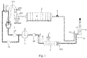
- Fig. 1 is a schematic diagram of a device for mass-energy conversion recycling of dephosphorization converter gas for diversified blowing so as to realize efficient dephosphorization;
- a method for mass-energy conversion recycling of dephosphorization converter gas for diversified blowing so as to realize efficient dephosphorization comprises the steps: In a dephosphorization converter for duplex steelmaking, conducting cooling and dedusting on the gas emitted by the dephosphorization converter, and then burning the gas in a combustion chamber by using a combustion improver to convert the CO component in the gas into CO 2 , wherein the combustion chamber comprises a combustion improver nozzle and an ignition device, a lining of the combustion chamber is made of a refractory material, a housing is an evaporative cooling pipeline, and the evaporative cooling pipeline is connected with a steam drum to recover the heat generated in the combustion process, so that mass-energy conversion of the dephosphorization converter gas is realized to obtain mass-energy converted gas; and after cooling and pressurization, making part of the mass-energy converted gas enter a bottom blowing system of the dephosphorization converter as bottom blowing gas to realize bottom blowing stirring of the mass-energy converted gas, and the other part
- the gas flow rates in different smelting stages are different when the mass-energy converted gas is used for blowing dephosphorization, specifically:
- the temperature of a molten pool rises due to an oxidation reaction for slagging
- the top blowing mass-energy converted gas intensity is 0-0.5 Nm 3 /min/t
- the top blowing O 2 intensity is 1.0-2.5 Nm 3 /min/t
- the bottom blowing mass-energy converted gas intensity is 0.05-0.3 Nm 3 /min/t;
- the intensity of the mass-energy converted gas is increased, the dephosphorization temperature is controlled and stirring is strengthened, the top blowing mass-energy converted gas intensity is 0.2-1.0 Nm 3 /min/t, the top blowing O 2 intensity is 0.8-1.8 Nm 3 /min/t, and the bottom blowing mass-energy converted gas intensity is 0.1-0.5 Nm 3 /min/t;
- the temperature and composition of the molten pool are uniformized, further dephosphorization is carried out, the top blowing mass-energy converted gas intensity is 0.1-0.6 Nm 3 /min/t, the top blowing O 2 intensity is 1.0-2.0 Nm 3 /min/t, and the bottom blowing mass-energy converted gas intensity is 0.05-0.4 Nm 3 /min/t;
- the top blowing mass-energy converted gas is stopped, and the bottom blowing mass-energy converted gas intensity is 0.03-0.15 Nm 3 /min/t, so as to protect bottom blowing elements.
- the combustion improver is O 2 , and the consumption of the combustion improver changes with the content of CO in the gas emitted from the dephosphorization converter, and in order to ensure sufficient mass-energy conversion of the gas, the flow ratio of O 2 :CO should be kept at 0.5-1.5:1.
- the pressure of the mass-energy converted gas is guaranteed to be at least 0.01-0.5 MPa higher than the pressure of oxygen.
- the mass-energy converted gas can be provided to nitrogen sealing pipelines of the top blowing system, a dedusting system and a charging system of the converter, completely replacing N 2 for sealing of a top blowing spray gun, a dedusting smoke hood and a charging system unit of the dephosphorization converter, to prevent air from entering a flue, wherein the nitrogen sealing pipelines of the top blowing system, the dedusting system and the charging system of the converter exist on a converter in the prior art.
- a device for mass-energy conversion recycling of dephosphorization converter gas for diversified blowing so as to realize efficient dephosphorization comprises a dephosphorization converter for duplex steelmaking 1, a first cooling device, a dedusting device and an emission chimney 5.
- the first cooling device comprises an evaporative cooling flue 201, a cooler nozzle 202 and an evaporative cooler 203 which are connected in sequence
- the dedusting device is an electrostatic precipitator 3, which comprises a gas analyzer.
- the dephosphorization converter for duplex steelmaking 1 is connected with the evaporative cooling flue 201, the electrostatic precipitator 3 is connected with the evaporative cooler 203, and the emission chimney 5 is connected with the electrostatic precipitator 3; and the dephosphorization converter for duplex steelmaking 1 comprises a top blowing system 12 and a bottom blowing system 13, the top blowing system 12 and the bottom blowing system 13 respectively blow top blowing gas and bottom blowing gas from the top and bottom of the converter 1 to realize dephosphorization, and gas generated in the dephosphorization process sequentially passes through the evaporative cooling flue 201, the cooler nozzle 202, the evaporative cooler 203 and the electrostatic precipitator 3 for cooling and dedusting, and then enters a pipeline in front of the emission chimney 5.
- the electrostatic precipitator 3 is connected with the emission chimney 5 through a pipeline, the pipeline is provided with a fan 4 on the side near the electrostatic precipitator 3, an emission-side bell-shaped valve 14 is arranged on the side near the emission chimney 5, and the emission-side bell-shaped valve 14 and the emission chimney 5 are provided with two switching valves 15 and 16.
- the switching valve 15 enables the gas passing through the emission-side bell-shaped valve 14 to enter the emission chimney 5 and be discharged through the emission chimney 5, and when the total amount of CO and CO 2 in the gas is greater than 18%, the switching valve 16 enables the gas passing through the emission-side bell-shaped valve 14 to enter another pipeline.
- the device further comprises a combustion chamber 6, a second cooling device, a compressor 8, a buffer device 11 and a mixing device 17, and the second cooling device is a gas cooler 9.
- An air inlet of the combustion chamber 6 is connected with the above another pipeline, an air outlet of the combustion chamber 6 is connected with the gas cooler 9, and the gas cooler 9, the compressor 10 and the buffer device 11 are sequentially connected.
- the buffer device 11 is provided with two outlets, wherein one outlet is connected with the bottom blowing system 13 and the other outlet is connected with the top blowing system 12, the top blowing system 12 is provided with the mixing device 17, and an inlet of the mixing device 17 is also connected with an oxygen supply device.
- the cooled and dedusted gas enters the combustion chamber, the CO component in the emitted gas is combusted and converted into CO 2 to obtain mass-energy converted gas, the mass-energy converted gas enters the buffer device after being cooled and pressurized, then part of the mass-energy converted gas enters the bottom blowing system of the dephosphorization converter as bottom blowing gas, the other part enters the top blowing system of the dephosphorization converter as top blowing gas after being mixed with oxygen, and the mass-energy converted gas is mixed with the oxygen in the mixing device to obtain diversified gas O 2 -N 2 -CO 2 which enters the converter 1 through top blowing.
- the mixed diversified gas O 2 -N 2 -CO 2 is sprayed into the dephosphorization converter 1 through a 3-7-hole supersonic top blowing spray gun, and the bottom blowing mass-energy converted gas can be blown into the dephosphorization converter 1 through 4-16 annular gap type or porous plug type or sleeve type bottom blowing elements.
- the combustion chamber 6 comprises a combustion improver nozzle 601 and an ignition device, a lining of the combustion chamber is made of a refractory material, a housing is an evaporative cooling pipeline, and the evaporative cooling pipeline is connected with a steam drum 7 to recover the heat generated in the combustion process.
- the combustion improver is sprayed into the combustion chamber 6 through the nozzle 601, the combustion improver is oxygen, the consumption of the combustion improver changes with the composition of the dedusted gas, and the flow ratio of O 2 :CO is kept at 0.5-1.5:1, so as to ensure sufficient mass-energy conversion of the gas.
- a gas analyzer 8 is arranged at an air outlet of the combustion chamber 6.
- the pressure of the mass-energy converted gas compressed by the compressor 8 is 0.01-0.5 MPa higher than that of the oxygen in the oxygen supply device, so as to ensure smooth mixing of the mass-energy converted gas and oxygen in the mixing device 17.
- the principle of the invention is that the smelting process of the dephosphorization converter for duplex steelmaking is a selective oxidation process of phosphorus and carbon; in order to realize "dephosphorization and carbon preservation", the top blowing O 2 flow is small and the temperature is low, and the decarbonization reaction is limited; the CO content in the gas is only 5%-30%, the CO 2 content is 10%-30%, and the heat value of the gas is low, so the gas does not have recycling economic values; the CO content is low, the gas quality is poor, and the gas does not have the value of being recycled as fuel; at present, iron and steel enterprises all adopt emission treatment for the dephosphorization converter gas, which not only wastes resources and energy, but also pollutes the environment.
- the main components of the mass-energy converted gas are CO 2 , N 2 and a small amount of residual O 2 , wherein the content of CO 2 reaches 35% or above, and CO 2 is a low oxidative substance.
- an oxidation reaction can occur between CO 2 and elements C, Fe, Si and Mn in molten iron, and the reaction between CO 2 and elements C and Fe is an endothermic reaction, which is beneficial to controlling the dephosphorization temperature.
- a large number of CO bubbles generated by the reaction of CO 2 with elements in the molten pool float upwards and have strong chemical stirring force to strengthen the dynamic conditions of dephosphorization; and N 2 in the mass-energy converted gas does not react with elements in the molten pool, but the stirring in the dephosphorization molten pool can be strengthened to promote the dephosphorization reaction.
- This embodiment adopts the method and device in Embodiment 1, and the specific conditions are as follows:
- the change of the gas content during blowing is shown in Table 1.
- the instantaneous gas flow rate is 160,000-190,000 Nm 3 /h.
- the gas After passing through the evaporative cooling flue and a dry dedusting system for cooling and dedusting, the gas enters the combustion chamber through an emission pipeline, eight combustion nozzles are used to inject the combustion improver, and the flow rate of the combustion improver varies with the composition of the dephosphorization converter gas as shown in Table 1 below.
- Table 1 Dephosphorization Converter Gas and Flow Rate of Combustion Improver Blowing time (min) Composition of dephosphorization converter gas (%) Flow rate of combustion improver (Nm 3 /h) CO O 2 CO 2 N 2 1.0 1.50 2.31 15.05 81.14 Emission 2.0 10.15 0.31 19.15 70.39 11177.5 3.0 14.56 0.27 22.5 62.67 14076.0 4.0 18.41 0.28 23.8 57.51 17348.5 5.0 21.25 0.25 19.96 58.54 19762.5 6.0 25.67 0.35 19.55 54.43 24369.5
- the mass-energy converted gas is pressurized to 2.2 MPa or above by the compressor and stored in the buffer device, and the average composition comprises 39% of CO 2 , 59.25% of N 2 , and the balance of a small amount of residual gas.
- the mass-energy converted gas is blown into a diversified gas main pipe in an injection mode, and is mixed with oxygen through the gas mixing device, the evenly mixed diversified gas O 2 -N 2 -CO 2 is sprayed into the dephosphorization converter through a 4-hole supersonic top blowing spray gun, and the bottom blowing mass-energy converted gas is blown into the dephosphorization converter through 16 annular gap type bottom blowing elements.
- the top blowing mass-energy converted gas is stopped, and the bottom blowing mass-energy converted gas intensity is 0.05 Nm 3 /min/t, so as to protect bottom blowing elements.
- the mass-energy conversion amount of gas per ton of steel is 45 Nm 3
- 12 kg of steam can be recovered by the evaporative cooling device of the combustion chamber, thereby improving the dephosphorization rate by 7.5%
- the mass-energy converted gas of the invention can completely replace N 2 for sealing of accessory equipment of the dephosphorization converter.
Landscapes
- Engineering & Computer Science (AREA)
- Chemical & Material Sciences (AREA)
- Materials Engineering (AREA)
- Metallurgy (AREA)
- Organic Chemistry (AREA)
- Manufacturing & Machinery (AREA)
- Environmental & Geological Engineering (AREA)
- Carbon Steel Or Casting Steel Manufacturing (AREA)
- Waste-Gas Treatment And Other Accessory Devices For Furnaces (AREA)
Description
- The invention belongs to the field of the ferrous metallurgy technology and energy conservation and emission reduction, in particular to a dephosphorization pretreatment aspect of steelmaking, and particularly relates to a method and device for applying mass-energy conversion recycling of 30-350 ton dephosphorization converter gas to diversified top blowing and bottom blowing in a dephosphorization process to realize efficient dephosphorization and recycling of gas resources in a duplex steelmaking process.
- Dephosphorization in converter steelmaking is mainly carried out at a low temperature in the early smelting stage. If the oxygen supply flow is large, the dephosphorization reaction tends to be limited by the thermodynamic conditions of rapid temperature rise in a molten pool after a desiliconization reaction, resulting in difficulty in controlling the temperature in the blowing process and unstability in dephosphorization rate. If the oxygen supply flow is small, the stirring dynamic conditions in the molten pool are poor. In order to produce high-quality steel, enterprises including Japan's Nippon Steel, China's Baosteel, Shougang Jingtang Company adopt a converter duplex smelting process, in a duplex steelmaking dephosphorization converter, in order to control the temperature of the molten pool, low-flow oxygen supply for slag formation is usually used to control the temperature, so as to realize efficient dephosphorization, however, the stirring dynamic conditions in the dephosphorization converter are poor, and slag foaming is caused by serious steel liquid peroxidation, which limits the dephosphorization speed and efficiency. If the stirring capacity of the molten pool in the dephosphorization process can be improved, the dephosphorization rate will be improved.
- Every ton of steel produced by the dephosphorization converter may result in 20-40 m3 of coal gas, which contains 5%-30% of CO, 10%-30% of CO2, and the rest mainly N2 and a small amount of O2. Due to the low calorific value of dephosphorization converter gas, it has no recycling economic values, at present, domestic and foreign iron and steel enterprises all adopt emission treatment, which not only wastes resources and energy, but also pollutes the environment. If the mass-energy conversion of the dephosphorization converter gas can be applied to the smelting process of the dephosphorization converter as a way of resource recycling, it will strengthen the dynamic conditions of dephosphorization, improve the dephosphorization rate and reduce the exhaust emission.
US 3 772 000 A discloses a method for converting solid ferrous metal to steel.US 4 561 637 A describes an apparatus for heating a steel bath utilizing converter waste gas.WO 2005/093106 A1 discloses a method for dephosphorization of hot metal using a hot metal pretreatment vessel. - In order to solve the above problems, the invention provides a method and device for mass-energy conversion recycling of dephosphorization converter gas for diversified blowing so as to realize efficient dephosphorization in a converter duplex steelmaking process. Mass-energy conversion of the dephosphorization converter gas is realized in a combustion mode, the strong stirring and temperature control effects of N2 and CO2 in the mass-energy converted gas are utilized to provide good thermodynamic and dynamic conditions for a dephosphorization reaction, thus realizing the recycling of the dephosphorization converter gas after mass-energy conversion, and achieving the purpose of efficient dephosphorization.
- The invention is realized through the following technical solution:
A method for mass-energy conversion recycling of dephosphorization converter gas for diversified blowing so as to realize efficient dephosphorization is provided in appended claim 1. - Further, the gas flow rates in different smelting stages are different when the mass-energy converted gas is used for blowing dephosphorization, specifically:
In the early stage of blowing, the temperature rise of a molten pool due to an oxidation reaction is beneficial to slagging, the top blowing mass-energy converted gas intensity is 0-0.5 Nm3/min/t, the top blowing O2 intensity is 1.0-2.5 Nm3/min/t, and the bottom blowing mass-energy converted gas intensity is 0.05-0.3 Nm3/min/t; - In the middle stage of blowing, the intensity of the mass-energy converted gas is increased, the dephosphorization temperature is controlled and stirring is strengthened, the top blowing mass-energy converted gas intensity is 0.2-1.0 Nm3/min/t, the top blowing O2 intensity is 0.8-1.8 Nm3/min/t, and the bottom blowing mass-energy converted gas intensity is 0.1-0.5 Nm3/min/t;
- In the later stage of blowing, the temperature and composition of the molten pool are uniformized, further dephosphorization is carried out, the top blowing mass-energy converted gas intensity is 0.1-0.6 Nm3/min/t, the top blowing O2 intensity is 1.0-2.0 Nm3/min/t, and the bottom blowing mass-energy converted gas intensity is 0.05-0.4 Nm3/min/t;
- During charging, tapping and waiting, the top blowing mass-energy converted gas is stopped, and the bottom blowing mass-energy converted gas intensity is 0.03-0.15 Nm3/min/t, so as to protect bottom blowing elements. The combustion improver is O2, and the consumption of the combustion improver changes with the content of CO in the gas emitted from the dephosphorization converter, and in order to ensure sufficient mass-energy conversion of the gas, the flow ratio of 02:CO should be kept at 0.5-1.5:1.
- Further, during the mixing process of the mass-energy converted gas and oxygen, the pressure of the mass-energy converted gas is guaranteed to be 0.01-0.5 MPa higher than the pressure of oxygen.
- Further, the emitted gas after cooling and dedusting is combusted in a combustion chamber, the combustion chamber comprises a combustion improver nozzle and an ignition device, a lining of the combustion chamber is made of a refractory material, a housing is an evaporative cooling pipeline, and the evaporative cooling pipeline is connected with a steam drum to recover the heat generated in the combustion process.
- Further, the mass-energy converted gas can be provided to nitrogen sealing pipelines of the top blowing system, a dedusting system and a charging system of the converter, completely replacing N2 for sealing of a top blowing spray gun, a dedusting smoke hood and a charging system unit of the dephosphorization converter, to prevent air from entering a flue.
- A device for mass-energy conversion recycling of dephosphorization converter gas for diversified blowing so as to realize efficient dephosphorization is provided. The device comprises a dephosphorization converter for duplex steelmaking, a first cooling device, a dedusting device and an emission chimney; the dephosphorization converter for duplex steelmaking is connected with the cooling device, the dedusting device is connected with the cooling device, and the emission chimney is connected with the dedusting device; the dephosphorization converter for duplex steelmaking comprises a top blowing system and a bottom blowing system; the top blowing system and the bottom blowing system respectively blow top blowing gas and bottom blowing gas from the top and bottom of the converter to realize dephosphorization, and the gas generated in the dephosphorization process sequentially passes through the cooling device and the dedusting device for cooling and dedusting, and then enters a pipeline in front of the emission chimney;
- The device further comprises a combustion chamber, a second cooling device, a compressor, a buffer device and a mixing device;
- An air inlet of the combustion chamber is connected with a pipeline between the dedusting device and the emission chimney;
- An air outlet of the combustion chamber is connected with the second cooling device;
- The second cooling device, the compressor and the buffer device are sequentially connected; The buffer device is provided with two outlets, wherein one outlet is connected with the bottom blowing system and the other outlet is connected with an inlet of the mixing device;
- The inlet of the mixing device is also connected with an oxygen supply device;
- The mixing device is connected with the top blowing system;
- The cooled and dedusted gas enters the combustion chamber, the CO component in the emitted gas is combusted and converted into CO2 to obtain mass-energy converted gas, the mass-energy converted gas enters the buffer device after being cooled and pressurized, then part of the mass-energy converted gas enters the bottom blowing system of the dephosphorization converter as bottom blowing gas, and the other part enters the top blowing system of the dephosphorization converter as top blowing gas after being mixed with oxygen.
- Further, the combustion chamber comprises a combustion improver nozzle and an ignition device, a lining of the combustion chamber is made of a refractory material, a housing is an evaporative cooling pipeline, and the evaporative cooling pipeline is connected with a steam drum to recover the heat generated in the combustion process.
- Further, a gas analyzer is arranged at an air outlet of the combustion chamber.
- Furthermore, a gas analyzer is arranged in the dedusting device.
- The invention has the beneficial technical effects that: the method is suitable for a 30-350 ton dephosphorization converter, and the mass-energy conversion amount of gas per ton of steel is 10-50 Nm3; meanwhile, by means of the evaporative cooling device of the combustion chamber, 5-20 kg of steam can be recovered; and the strong stirring and temperature control effects of N2 and CO2 provide good thermodynamic and dynamic conditions for the dephosphorization converter, thereby improving the dephosphorization rate by 5% or above.
-
Fig. 1 is a schematic diagram of a device for mass-energy conversion recycling of dephosphorization converter gas for diversified blowing so as to realize efficient dephosphorization; - Wherein, 1. converter, 201. evaporative cooling flue, 202. cooler nozzle, 203. evaporative cooler, 3. electrostatic precipitator, 4. fan, 5. emission chimney, 6. combustion chamber, 601. combustion improver device nozzle, 7. steam recovery device, 8. gas analyzer, 9. gas cooler, 10. compressor, 11. buffer device, 12. top blowing system, 13. bottom blowing system, 14. emission-side bell-shaped valve, 15. first switching valve, 16. second switching valve, and 17. mixing device.
- In order to make the object, technical solution and advantages of the invention clearer, the invention will be described in further detail below with reference to the drawings and embodiments. It should be understood that the specific embodiments described herein are only used to illustrate the invention and are not used to limit the invention.
- On the contrary, the present invention covers any alternatives, modifications, equivalent methods and solutions defined by the claims within the spirit and scope of the present invention. Further, in order to enable the public to have a better understanding of the present invention, in the following detailed description of the present invention, some specific details are described. It will be apparent to those skilled in the art that the present invention can be fully understood without the description of these details.
- A method for mass-energy conversion recycling of dephosphorization converter gas for diversified blowing so as to realize efficient dephosphorization is provided, and the method comprises the steps:
In a dephosphorization converter for duplex steelmaking, conducting cooling and dedusting on the gas emitted by the dephosphorization converter, and then burning the gas in a combustion chamber by using a combustion improver to convert the CO component in the gas into CO2, wherein the combustion chamber comprises a combustion improver nozzle and an ignition device, a lining of the combustion chamber is made of a refractory material, a housing is an evaporative cooling pipeline, and the evaporative cooling pipeline is connected with a steam drum to recover the heat generated in the combustion process, so that mass-energy conversion of the dephosphorization converter gas is realized to obtain mass-energy converted gas; and after cooling and pressurization, making part of the mass-energy converted gas enter a bottom blowing system of the dephosphorization converter as bottom blowing gas to realize bottom blowing stirring of the mass-energy converted gas, and the other part enter a top blowing system of the dephosphorization converter as top blowing gas after being mixed with oxygen, so as to realize diversified gas O2-N2-CO2 blowing dephosphorization, as a replacement for the existing way of top blowing part of O2 and bottom blowing Ar/N2 into the dephosphorization converter, thereby realizing recycling of the converted gas for efficient dephosphorization. - The gas flow rates in different smelting stages are different when the mass-energy converted gas is used for blowing dephosphorization, specifically:
In the early stage of blowing, the temperature of a molten pool rises due to an oxidation reaction for slagging, the top blowing mass-energy converted gas intensity is 0-0.5 Nm3/min/t, the top blowing O2 intensity is 1.0-2.5 Nm3/min/t, and the bottom blowing mass-energy converted gas intensity is 0.05-0.3 Nm3/min/t; - In the middle stage of blowing, the intensity of the mass-energy converted gas is increased, the dephosphorization temperature is controlled and stirring is strengthened, the top blowing mass-energy converted gas intensity is 0.2-1.0 Nm3/min/t, the top blowing O2 intensity is 0.8-1.8 Nm3/min/t, and the bottom blowing mass-energy converted gas intensity is 0.1-0.5 Nm3/min/t;
- In the later stage of blowing, the temperature and composition of the molten pool are uniformized, further dephosphorization is carried out, the top blowing mass-energy converted gas intensity is 0.1-0.6 Nm3/min/t, the top blowing O2 intensity is 1.0-2.0 Nm3/min/t, and the bottom blowing mass-energy converted gas intensity is 0.05-0.4 Nm3/min/t;
- During charging, tapping and waiting, the top blowing mass-energy converted gas is stopped, and the bottom blowing mass-energy converted gas intensity is 0.03-0.15 Nm3/min/t, so as to protect bottom blowing elements.
- The combustion improver is O2, and the consumption of the combustion improver changes with the content of CO in the gas emitted from the dephosphorization converter, and in order to ensure sufficient mass-energy conversion of the gas, the flow ratio of O2:CO should be kept at 0.5-1.5:1.
- During the mixing process of the mass-energy converted gas and oxygen, the pressure of the mass-energy converted gas is guaranteed to be at least 0.01-0.5 MPa higher than the pressure of oxygen.
- Meanwhile, the mass-energy converted gas can be provided to nitrogen sealing pipelines of the top blowing system, a dedusting system and a charging system of the converter, completely replacing N2 for sealing of a top blowing spray gun, a dedusting smoke hood and a charging system unit of the dephosphorization converter, to prevent air from entering a flue, wherein the nitrogen sealing pipelines of the top blowing system, the dedusting system and the charging system of the converter exist on a converter in the prior art.
- A device for mass-energy conversion recycling of dephosphorization converter gas for diversified blowing so as to realize efficient dephosphorization is provided. The device comprises a dephosphorization converter for duplex steelmaking 1, a first cooling device, a dedusting device and an emission chimney 5.
- Wherein, the first cooling device comprises an
evaporative cooling flue 201, acooler nozzle 202 and anevaporative cooler 203 which are connected in sequence, and the dedusting device is an electrostatic precipitator 3, which comprises a gas analyzer. - The dephosphorization converter for duplex steelmaking 1 is connected with the
evaporative cooling flue 201, the electrostatic precipitator 3 is connected with theevaporative cooler 203, and the emission chimney 5 is connected with the electrostatic precipitator 3; and the dephosphorization converter for duplex steelmaking 1 comprises atop blowing system 12 and a bottom blowing system 13, thetop blowing system 12 and the bottom blowing system 13 respectively blow top blowing gas and bottom blowing gas from the top and bottom of the converter 1 to realize dephosphorization, and gas generated in the dephosphorization process sequentially passes through theevaporative cooling flue 201, thecooler nozzle 202, theevaporative cooler 203 and the electrostatic precipitator 3 for cooling and dedusting, and then enters a pipeline in front of the emission chimney 5. - The electrostatic precipitator 3 is connected with the emission chimney 5 through a pipeline, the pipeline is provided with a fan 4 on the side near the electrostatic precipitator 3, an emission-side bell-shaped valve 14 is arranged on the side near the emission chimney 5, and the emission-side bell-shaped valve 14 and the emission chimney 5 are provided with two switching
valves valve 15 enables the gas passing through the emission-side bell-shaped valve 14 to enter the emission chimney 5 and be discharged through the emission chimney 5, and when the total amount of CO and CO2 in the gas is greater than 18%, the switchingvalve 16 enables the gas passing through the emission-side bell-shaped valve 14 to enter another pipeline. - The device further comprises a combustion chamber 6, a second cooling device, a compressor 8, a
buffer device 11 and amixing device 17, and the second cooling device is a gas cooler 9. - An air inlet of the combustion chamber 6 is connected with the above another pipeline, an air outlet of the combustion chamber 6 is connected with the gas cooler 9, and the gas cooler 9, the
compressor 10 and thebuffer device 11 are sequentially connected. - The
buffer device 11 is provided with two outlets, wherein one outlet is connected with the bottom blowing system 13 and the other outlet is connected with thetop blowing system 12, thetop blowing system 12 is provided with the mixingdevice 17, and an inlet of the mixingdevice 17 is also connected with an oxygen supply device. - The cooled and dedusted gas enters the combustion chamber, the CO component in the emitted gas is combusted and converted into CO2 to obtain mass-energy converted gas, the mass-energy converted gas enters the buffer device after being cooled and pressurized, then part of the mass-energy converted gas enters the bottom blowing system of the dephosphorization converter as bottom blowing gas, the other part enters the top blowing system of the dephosphorization converter as top blowing gas after being mixed with oxygen, and the mass-energy converted gas is mixed with the oxygen in the mixing device to obtain diversified gas O2-N2-CO2 which enters the converter 1 through top blowing.
- The mixed diversified gas O2-N2-CO2 is sprayed into the dephosphorization converter 1 through a 3-7-hole supersonic top blowing spray gun, and the bottom blowing mass-energy converted gas can be blown into the dephosphorization converter 1 through 4-16 annular gap type or porous plug type or sleeve type bottom blowing elements.
- The combustion chamber 6 comprises a
combustion improver nozzle 601 and an ignition device, a lining of the combustion chamber is made of a refractory material, a housing is an evaporative cooling pipeline, and the evaporative cooling pipeline is connected with a steam drum 7 to recover the heat generated in the combustion process. - The combustion improver is sprayed into the combustion chamber 6 through the
nozzle 601, the combustion improver is oxygen, the consumption of the combustion improver changes with the composition of the dedusted gas, and the flow ratio of O2:CO is kept at 0.5-1.5:1, so as to ensure sufficient mass-energy conversion of the gas. - In order to monitor the composition of the gas discharged through the combustion chamber, a gas analyzer 8 is arranged at an air outlet of the combustion chamber 6.
- Since the amount of oxygen in the
mixing device 17 is significantly higher than that of the mass-energy converted gas during mixing, the pressure of the mass-energy converted gas compressed by the compressor 8 is 0.01-0.5 MPa higher than that of the oxygen in the oxygen supply device, so as to ensure smooth mixing of the mass-energy converted gas and oxygen in themixing device 17. - The principle of the invention is that the smelting process of the dephosphorization converter for duplex steelmaking is a selective oxidation process of phosphorus and carbon; in order to realize "dephosphorization and carbon preservation", the top blowing O2 flow is small and the temperature is low, and the decarbonization reaction is limited; the CO content in the gas is only 5%-30%, the CO2 content is 10%-30%, and the heat value of the gas is low, so the gas does not have recycling economic values; the CO content is low, the gas quality is poor, and the gas does not have the value of being recycled as fuel; at present, iron and steel enterprises all adopt emission treatment for the dephosphorization converter gas, which not only wastes resources and energy, but also pollutes the environment.
- According to the invention, O2 is blown by the combustion improver nozzle arranged in the combustion chamber, so that the reaction 2CO+O2=2CO2 occurs, CO in low-quality dephosphorization converter gas is converted into CO2, and the energy generated by combustion is recovered at the same time, so that mass-energy conversion is realized. The main components of the mass-energy converted gas are CO2, N2 and a small amount of residual O2, wherein the content of CO2 reaches 35% or above, and CO2 is a low oxidative substance. At the steelmaking temperature, an oxidation reaction can occur between CO2 and elements C, Fe, Si and Mn in molten iron, and the reaction between CO2 and elements C and Fe is an endothermic reaction, which is beneficial to controlling the dephosphorization temperature. Meanwhile, a large number of CO bubbles generated by the reaction of CO2 with elements in the molten pool float upwards and have strong chemical stirring force to strengthen the dynamic conditions of dephosphorization; and N2 in the mass-energy converted gas does not react with elements in the molten pool, but the stirring in the dephosphorization molten pool can be strengthened to promote the dephosphorization reaction.
- This embodiment adopts the method and device in Embodiment 1, and the specific conditions are as follows:
For a 300 t dephosphorization converter, the change of the gas content during blowing is shown in Table 1. The instantaneous gas flow rate is 160,000-190,000 Nm3/h. After passing through the evaporative cooling flue and a dry dedusting system for cooling and dedusting, the gas enters the combustion chamber through an emission pipeline, eight combustion nozzles are used to inject the combustion improver, and the flow rate of the combustion improver varies with the composition of the dephosphorization converter gas as shown in Table 1 below.Table 1 Dephosphorization Converter Gas and Flow Rate of Combustion Improver Blowing time (min) Composition of dephosphorization converter gas (%) Flow rate of combustion improver (Nm3/h) CO O2 CO2 N2 1.0 1.50 2.31 15.05 81.14 Emission 2.0 10.15 0.31 19.15 70.39 11177.5 3.0 14.56 0.27 22.5 62.67 14076.0 4.0 18.41 0.28 23.8 57.51 17348.5 5.0 21.25 0.25 19.96 58.54 19762.5 6.0 25.67 0.35 19.55 54.43 24369.5 - The mass-energy converted gas is pressurized to 2.2 MPa or above by the compressor and stored in the buffer device, and the average composition comprises 39% of CO2, 59.25% of N2, and the balance of a small amount of residual gas. The mass-energy converted gas is blown into a diversified gas main pipe in an injection mode, and is mixed with oxygen through the gas mixing device, the evenly mixed diversified gas O2-N2-CO2 is sprayed into the dephosphorization converter through a 4-hole supersonic top blowing spray gun, and the bottom blowing mass-energy converted gas is blown into the dephosphorization converter through 16 annular gap type bottom blowing elements.
- The specific blowing process comprises the following steps:
In the early stage of blowing, the oxygen blowing ratio should be increased, which is conducive to the temperature rise of the molten pool and rapid slag formation, the top blowing mass-energy converted gas intensity is 0.2 Nm3/min/t, the top blowing O2 intensity is 1.8 Nm3/min/t, the top blowing diversified gas ratio is CO2:N2:O2 = 1:1.5:23, and the bottom blowing mass-energy converted gas intensity is 0.2 Nm3/min/t; - In the middle stage of blowing, it is required to strengthen the mixing in the molten pool and control the temperature of the dephosphorization molten pool, therefore, the mass-energy converted gas blowing intensity should be increased, the top blowing mass-energy converted gas intensity is 0.9 Nm3/min/t, the top blowing O2 intensity is 0.9 Nm3/min/t, the top blowing diversified gas ratio is CO2:N2:O2=1:1.5:2.6, and the bottom blowing mass-energy converted gas intensity is 0.3 Nm3/min/t;
- In the later stage of blowing, the temperature and composition of the molten pool are uniformized, further dephosphorization is carried out, converted gas intensity is appropriately reduced, the top blowing mass-energy converted gas intensity is 0.4 Nm3/min/t, the top blowing O2 intensity is 1.4 Nm3/min/t, the top blowing diversified gas ratio is CO2:N2:O2=1:1.5:9, and the bottom blowing mass-energy converted gas intensity is 0.3 Nm3/min/t;
- During charging, tapping and waiting, the top blowing mass-energy converted gas is stopped, and the bottom blowing mass-energy converted gas intensity is 0.05 Nm3/min/t, so as to protect bottom blowing elements.
- When the method of the invention is applied to a 300 t dephosphorization converter, the mass-energy conversion amount of gas per ton of steel is 45 Nm3, 12 kg of steam can be recovered by the evaporative cooling device of the combustion chamber, thereby improving the dephosphorization rate by 7.5%, and the mass-energy converted gas of the invention can completely replace N2 for sealing of accessory equipment of the dephosphorization converter.
Claims (9)
- A method for mass-energy conversion recycling of dephosphorization converter gas for diversified blowing so as to realize efficient dephosphorization, wherein, comprising:in a dephosphorization converter for duplex steelmaking (1), conducting cooling and dedusting on the gas emitted by the dephosphorization converter, then burning the gas by using a combustion improver to convert the CO component in the gas into CO2, and meanwhile, recovering the heat generated by combustion, so that mass-energy conversion of the dephosphorization converter gas is realized to obtain mass-energy converted gas;after cooling and pressurization, part of the mass-energy converted gas entering a bottom blowing system (13) of the dephosphorization converter as bottom blowing gas to realize bottom blowing stirring of the mass-energy converted gas in the converter, and the other part entering a top blowing system (12) of the dephosphorization converter as top blowing gas after being mixed with oxygen, so as to realize diversified gas O2-N2-CO2 blowing dephosphorization in the converter, as a replacement for the existing way of top blowing part of O2 and bottom blowing N2 into the dephosphorization converter, thereby realizing recycling of the converted gas for efficient dephosphorization; wherein the process of diversified blowing for efficient dephosphorization is controlled in stages,wherein, the combustion improver is O2, and the consumption of the combustion improver changes with the content of CO in the gas emitted from the dephosphorization converter, and in order to ensure sufficient mass-energy conversion of the gas, the flow ratio of O2:CO should be kept at 0.5-1.5:1.
- The method according to claim 1, wherein, the gas flow rates in different smelting stages are different when the mass-energy converted gas is used for blowing dephosphorization, specifically:in an early stage of blowing (blowing quantity of top blowing gas of 0-25%), the temperature of a molten pool rises due to an oxidation reaction for slagging, the top blowing mass-energy converted gas intensity is 0-0.5 Nm3/min/t, the top blowing O2 intensity is 1.0-2.5 Nm3/min/t, and the bottom blowing mass-energy converted gas intensity is 0.05-0.3 Nm3/min/t;in a middle stage of blowing (blowing quantity of top blowing gas of 26-85%), the intensity of the mass-energy converted gas is increased, the dephosphorization temperature is controlled and stirring is strengthened, the top blowing mass-energy converted gas intensity is 0.2-1.0 Nm3/min/t, the top blowing O2 intensity is 0.8-1.8 Nm3/min/t, and the bottom blowing mass-energy converted gas intensity is 0.1-0.5 Nm3/min/t;in a later stage of blowing (blowing quantity of top blowing gas of 86-100%), the temperature and composition of the molten pool are uniformized, further dephosphorization is carried out, the top blowing mass-energy converted gas intensity is 0.1-0.6 Nm3/min/t, the top blowing O2 intensity is 1.0-2.0 Nm3/min/t, and the bottom blowing mass-energy converted gas intensity is 0.05-0.4 Nm3/min/t;during charging, tapping and waiting, the top blowing mass-energy converted gas is stopped, and the bottom blowing mass-energy converted gas intensity is 0.03-0.15 Nm3/min/t, so as to protect bottom blowing elements.
- The method according to claim 1, wherein, during the mixing process of the mass-energy converted gas and oxygen, the pressure of the mass-energy converted gas is guaranteed to be 0.01-0.5 MPa higher than the pressure of oxygen.
- The method according to claim 1, wherein, the emitted gas after cooling and dedusting is combusted in a combustion chamber (6), the combustion chamber (6) comprises a combustion improver nozzle and an ignition device, a lining of the combustion chamber (6) is made of a refractory material, a housing is an evaporative cooling pipeline, and the evaporative cooling pipeline is connected with a steam drum to recover the heat generated in the combustion process.
- The method according to claim 1, wherein, the mass-energy converted gas can be provided to nitrogen sealing pipelines of the top blowing system (12), a dedusting system and a charging system of the converter, completely replacing N2 for sealing of a top blowing spray gun, a dedusting smoke hood and a charging system unit of the dephosphorization converter, to prevent air from entering a flue.
- A device for mass-energy conversion recycling of dephosphorization converter gas for diversified blowing so as to realize efficient dephosphorization, the device comprising a dephosphorization converter for duplex steelmaking (1), a first cooling device, a dedusting device and an emission chimney (5); wherein the dephosphorization converter for duplex steelmaking (1) is connected with the cooling device, the dedusting device is connected with the cooling device, and the emission chimney (5) is connected with the dedusting device; the dephosphorization converter for duplex steelmaking (1) comprises a top blowing system (12) and a bottom blowing system (13); the top blowing system (12) and the bottom blowing system (13) respectively blow top blowing gas and bottom blowing gas from the top and bottom of the converter to realize dephosphorization process, and the gas generated in the dephosphorization process sequentially passes through the cooling device and the dedusting device for cooling and dedusting, and then enters a pipeline in front of the emission chimney (5); wherein,the device further comprises a combustion chamber (6), a second cooling device, a compressor (10), a buffer device (11) and a mixing device (17);an air inlet of the combustion chamber (6) is connected with a pipeline between the dedusting device and the emission chimney (5);an air outlet of the combustion chamber (6) is connected with the second cooling device;the second cooling device, the compressor (10) and the buffer device (11) are sequentially connected;the buffer device (11) is provided with two outlets, wherein one outlet is connected with the bottom blowing system (13), and the other outlet is connected with an inlet of the mixing device (17);the inlet of the mixing device (17) is also connected with an oxygen supply device;the mixing device (17) is connected with the top blowing system (12);the cooled and dedusted gas enters the combustion chamber (6), the CO component in the emitted gas is combusted and converted into CO2 to obtain mass-energy converted gas, the mass-energy converted gas enters the buffer device (11) after being cooled and pressurized, then part of the mass-energy converted gas enters the bottom blowing system (13) of the dephosphorization converter as bottom blowing gas, and the other part enters the top blowing system (12) of the dephosphorization converter as top blowing gas after being mixed with oxygen.
- The device according to claim 6, wherein, the combustion chamber (6) comprises a combustion improver nozzle and an ignition device, a lining of the combustion chamber (6) is made of a refractory material, a housing is an evaporative cooling pipeline, and the evaporative cooling pipeline is connected with a steam drum to recover the heat generated in the combustion process.
- The device according to claim 6, wherein, a gas analyzer (8) is arranged at an air outlet of the combustion chamber (6).
- The device according to claim 6, wherein, a gas analyzer (8) is arranged in the dedusting device.
Applications Claiming Priority (2)
| Application Number | Priority Date | Filing Date | Title |
|---|---|---|---|
| CN201710301930.4A CN107151724B (en) | 2017-05-02 | 2017-05-02 | The polynary blowing high efficiency dephosphorating method and apparatus of dephosphorization converter coal gas mass-energy conversion cycle |
| PCT/CN2017/087812 WO2018201552A1 (en) | 2017-05-02 | 2017-06-09 | Method and apparatus for high-efficiency dephosphorization by mass-energy conversion cycling and multi-component blowing for dephosphorization converter gas |
Publications (3)
| Publication Number | Publication Date |
|---|---|
| EP3620541A1 EP3620541A1 (en) | 2020-03-11 |
| EP3620541A4 EP3620541A4 (en) | 2020-04-08 |
| EP3620541B1 true EP3620541B1 (en) | 2021-10-06 |
Family
ID=59793550
Family Applications (1)
| Application Number | Title | Priority Date | Filing Date |
|---|---|---|---|
| EP17908116.1A Active EP3620541B1 (en) | 2017-05-02 | 2017-06-09 | Method and apparatus for high-efficiency dephosphorization by mass-energy conversion cycling and multi-component blowing for dephosphorization converter gas |
Country Status (3)
| Country | Link |
|---|---|
| EP (1) | EP3620541B1 (en) |
| CN (1) | CN107151724B (en) |
| WO (1) | WO2018201552A1 (en) |
Families Citing this family (5)
| Publication number | Priority date | Publication date | Assignee | Title |
|---|---|---|---|---|
| TWI703219B (en) * | 2018-04-24 | 2020-09-01 | 日商日本製鐵股份有限公司 | Dephosphorization method of hot metal |
| CN109234490B (en) * | 2018-11-07 | 2020-06-26 | 北京科技大学 | High-efficiency long-life blowing method and system for vanadium extraction-decarburization duplex converter |
| CN109913614B (en) * | 2019-02-01 | 2023-11-07 | 无锡红旗除尘设备有限公司 | Ultralow emission purifying treatment system for converter primary dry dedusting and diffusing flue gas |
| CN109837358B (en) * | 2019-03-26 | 2020-04-14 | 东北大学 | A system and method for self-circulating compound blowing of steelmaking flue gas |
| CN115319417A (en) * | 2022-08-20 | 2022-11-11 | 欧萨斯能源环境设备(南京)有限公司 | Manufacturing process of converter water-cooling flue |
Family Cites Families (11)
| Publication number | Priority date | Publication date | Assignee | Title |
|---|---|---|---|---|
| US3772000A (en) * | 1971-11-23 | 1973-11-13 | Columbia Gas Syst | Method for converting solid ferrous metal to steel |
| US3998626A (en) * | 1973-03-12 | 1976-12-21 | Pennsylvania Engineering Corporation | Method for air pollution control combined with safe recovery and control of gases from a bottom-blown steel converter vessel |
| JPS55104416A (en) * | 1979-01-31 | 1980-08-09 | Nippon Steel Corp | Oxygen top blowing steel making method using converter non-combustion exhaust gas |
| SU1032023A2 (en) * | 1981-07-06 | 1983-07-30 | Украинский Государственный Институт По Проектированию Металлургических Заводов | Method for protecting oxygen tuyerers in bottom blow converters |
| LU84390A1 (en) * | 1982-09-27 | 1984-04-24 | Arbed | METHOD AND DEVICE FOR HEATING A STEEL BATH FILLED WITH SCRAP |
| JP4779388B2 (en) * | 2004-03-25 | 2011-09-28 | Jfeスチール株式会社 | How to remove hot metal |
| CN1664118A (en) * | 2005-03-25 | 2005-09-07 | 北京科技大学 | A Converter Steelmaking Process with CO2 Gas Injection |
| CN101694352A (en) * | 2009-09-17 | 2010-04-14 | 无锡市东方环境工程设计研究所有限公司 | Waste heat recovery system of exhaust gas of metallurgical converter |
| CN101818227A (en) * | 2010-05-05 | 2010-09-01 | 北京科技大学 | Method for recycling CO2 separated from converter steel-making gas for top blowing and bottom blowing |
| CN201809374U (en) * | 2010-09-08 | 2011-04-27 | 北京科技大学 | Device for recycling converter coal gas generated from low-concentration carbon monoxide (CO) burner gas of converter |
| CN104928439B (en) * | 2015-07-08 | 2017-11-17 | 北京科技大学 | One kind utilizes CO2The method that dephosphorization efficiency is improved in duplex converter |
-
2017
- 2017-05-02 CN CN201710301930.4A patent/CN107151724B/en active Active
- 2017-06-09 WO PCT/CN2017/087812 patent/WO2018201552A1/en not_active Ceased
- 2017-06-09 EP EP17908116.1A patent/EP3620541B1/en active Active
Non-Patent Citations (1)
| Title |
|---|
| None * |
Also Published As
| Publication number | Publication date |
|---|---|
| EP3620541A4 (en) | 2020-04-08 |
| EP3620541A1 (en) | 2020-03-11 |
| CN107151724A (en) | 2017-09-12 |
| CN107151724B (en) | 2019-03-29 |
| WO2018201552A1 (en) | 2018-11-08 |
Similar Documents
| Publication | Publication Date | Title |
|---|---|---|
| EP3620541A1 (en) | Method and apparatus for high-efficiency dephosphorization by mass-energy conversion cycling and multi-component blowing for dephosphorization converter gas | |
| Fucheng et al. | Prospects for green steelmaking technology with low carbon emissions in China | |
| CN101818227A (en) | Method for recycling CO2 separated from converter steel-making gas for top blowing and bottom blowing | |
| CN113774178A (en) | Production system of Ou metallurgical furnace and hydrogen-rich carbon circulation blast furnace coupling | |
| CN101603104A (en) | CO in blast furnace and the coal gas of converter 2Separation and Recovery and cyclic utilization method | |
| CN101956038B (en) | Process method and device for performing lower-carbon ironmaking and steelmaking through melting reduction of iron ore | |
| CN103060510A (en) | High scrap ratio smelting method by adopting gas to heat | |
| CN105969937B (en) | It is a kind of to use the electric-arc furnace steelmaking boundling method for supplying oxygen for becoming calorific value fuel gas | |
| CN105238903A (en) | Method for achieving splashing slag furnace protecting work by means of converter gas | |
| CN105624358B (en) | A kind of method of single-turn stove dioxygen rifle production Low-phosphorus Steel | |
| CN107130079B (en) | It is a kind of to prepare CO using coal gas of converter2And the method and system of cycle injection | |
| CN209752602U (en) | Smoke dust adsorption equipment for steelmaking | |
| CN108300831A (en) | Method for improving heat source in smelting process of dephosphorization converter | |
| CN106978517B (en) | Modify the method and apparatus that converter emission coal gas recycling is applied to steel-making bottom blowing | |
| CN217103952U (en) | Ou ye stove jetting composite tuyere device | |
| CN209722190U (en) | A kind of quasi- pure oxygen ironmaking and blast furnace gas recycling device | |
| CN108977620B (en) | A single-channel secondary combustion oxygen lance for improving the scrap ratio in converters and its use method | |
| CN213778596U (en) | Heating electrode device capable of blowing powder for electric arc furnace | |
| CN111763794B (en) | A method for smelting stainless steel by mixing chrome ore powder and carbon powder in a TSR converter | |
| CN101250606A (en) | Method for reducing dust of steel mill by using CO2 | |
| WO2025036019A1 (en) | Steel smelting system and method based on hydrogen-rich reducing gas injection | |
| CN116287504B (en) | Method for utilizing carbon dioxide by high oxygen enrichment and total oxygen blast furnace injection | |
| CN108949245A (en) | A kind of coupling coal gasification realizes the device and method of blast furnace iron-making process carbon capture | |
| CN114875200A (en) | Method for preventing corrosion and water leakage of converter oxygen lance nozzle end face under dry dedusting condition | |
| CN114657317B (en) | Low-carbon metallurgy method |
Legal Events
| Date | Code | Title | Description |
|---|---|---|---|
| STAA | Information on the status of an ep patent application or granted ep patent |
Free format text: STATUS: THE INTERNATIONAL PUBLICATION HAS BEEN MADE |
|
| PUAI | Public reference made under article 153(3) epc to a published international application that has entered the european phase |
Free format text: ORIGINAL CODE: 0009012 |
|
| STAA | Information on the status of an ep patent application or granted ep patent |
Free format text: STATUS: REQUEST FOR EXAMINATION WAS MADE |
|
| 17P | Request for examination filed |
Effective date: 20191107 |
|
| AK | Designated contracting states |
Kind code of ref document: A1 Designated state(s): AL AT BE BG CH CY CZ DE DK EE ES FI FR GB GR HR HU IE IS IT LI LT LU LV MC MK MT NL NO PL PT RO RS SE SI SK SM TR |
|
| AX | Request for extension of the european patent |
Extension state: BA ME |
|
| A4 | Supplementary search report drawn up and despatched |
Effective date: 20200305 |
|
| RIC1 | Information provided on ipc code assigned before grant |
Ipc: C21C 5/38 20060101ALI20200228BHEP Ipc: C21C 5/40 20060101ALI20200228BHEP Ipc: C21C 7/064 20060101ALI20200228BHEP Ipc: C21C 5/35 20060101AFI20200228BHEP |
|
| DAV | Request for validation of the european patent (deleted) | ||
| DAX | Request for extension of the european patent (deleted) | ||
| STAA | Information on the status of an ep patent application or granted ep patent |
Free format text: STATUS: EXAMINATION IS IN PROGRESS |
|
| 17Q | First examination report despatched |
Effective date: 20201104 |
|
| GRAP | Despatch of communication of intention to grant a patent |
Free format text: ORIGINAL CODE: EPIDOSNIGR1 |
|
| STAA | Information on the status of an ep patent application or granted ep patent |
Free format text: STATUS: GRANT OF PATENT IS INTENDED |
|
| INTG | Intention to grant announced |
Effective date: 20210608 |
|
| GRAS | Grant fee paid |
Free format text: ORIGINAL CODE: EPIDOSNIGR3 |
|
| GRAA | (expected) grant |
Free format text: ORIGINAL CODE: 0009210 |
|
| STAA | Information on the status of an ep patent application or granted ep patent |
Free format text: STATUS: THE PATENT HAS BEEN GRANTED |
|
| AK | Designated contracting states |
Kind code of ref document: B1 Designated state(s): AL AT BE BG CH CY CZ DE DK EE ES FI FR GB GR HR HU IE IS IT LI LT LU LV MC MK MT NL NO PL PT RO RS SE SI SK SM TR |
|
| REG | Reference to a national code |
Ref country code: GB Ref legal event code: FG4D |
|
| REG | Reference to a national code |
Ref country code: CH Ref legal event code: EP Ref country code: AT Ref legal event code: REF Ref document number: 1436284 Country of ref document: AT Kind code of ref document: T Effective date: 20211015 |
|
| REG | Reference to a national code |
Ref country code: IE Ref legal event code: FG4D |
|
| REG | Reference to a national code |
Ref country code: DE Ref legal event code: R096 Ref document number: 602017047379 Country of ref document: DE |
|
| REG | Reference to a national code |
Ref country code: LT Ref legal event code: MG9D |
|
| REG | Reference to a national code |
Ref country code: NL Ref legal event code: MP Effective date: 20211006 |
|
| REG | Reference to a national code |
Ref country code: AT Ref legal event code: MK05 Ref document number: 1436284 Country of ref document: AT Kind code of ref document: T Effective date: 20211006 |
|
| PG25 | Lapsed in a contracting state [announced via postgrant information from national office to epo] |
Ref country code: RS Free format text: LAPSE BECAUSE OF FAILURE TO SUBMIT A TRANSLATION OF THE DESCRIPTION OR TO PAY THE FEE WITHIN THE PRESCRIBED TIME-LIMIT Effective date: 20211006 Ref country code: LT Free format text: LAPSE BECAUSE OF FAILURE TO SUBMIT A TRANSLATION OF THE DESCRIPTION OR TO PAY THE FEE WITHIN THE PRESCRIBED TIME-LIMIT Effective date: 20211006 Ref country code: FI Free format text: LAPSE BECAUSE OF FAILURE TO SUBMIT A TRANSLATION OF THE DESCRIPTION OR TO PAY THE FEE WITHIN THE PRESCRIBED TIME-LIMIT Effective date: 20211006 Ref country code: BG Free format text: LAPSE BECAUSE OF FAILURE TO SUBMIT A TRANSLATION OF THE DESCRIPTION OR TO PAY THE FEE WITHIN THE PRESCRIBED TIME-LIMIT Effective date: 20220106 Ref country code: AT Free format text: LAPSE BECAUSE OF FAILURE TO SUBMIT A TRANSLATION OF THE DESCRIPTION OR TO PAY THE FEE WITHIN THE PRESCRIBED TIME-LIMIT Effective date: 20211006 |
|
| PG25 | Lapsed in a contracting state [announced via postgrant information from national office to epo] |
Ref country code: IS Free format text: LAPSE BECAUSE OF FAILURE TO SUBMIT A TRANSLATION OF THE DESCRIPTION OR TO PAY THE FEE WITHIN THE PRESCRIBED TIME-LIMIT Effective date: 20220206 Ref country code: SE Free format text: LAPSE BECAUSE OF FAILURE TO SUBMIT A TRANSLATION OF THE DESCRIPTION OR TO PAY THE FEE WITHIN THE PRESCRIBED TIME-LIMIT Effective date: 20211006 Ref country code: PT Free format text: LAPSE BECAUSE OF FAILURE TO SUBMIT A TRANSLATION OF THE DESCRIPTION OR TO PAY THE FEE WITHIN THE PRESCRIBED TIME-LIMIT Effective date: 20220207 Ref country code: PL Free format text: LAPSE BECAUSE OF FAILURE TO SUBMIT A TRANSLATION OF THE DESCRIPTION OR TO PAY THE FEE WITHIN THE PRESCRIBED TIME-LIMIT Effective date: 20211006 Ref country code: NO Free format text: LAPSE BECAUSE OF FAILURE TO SUBMIT A TRANSLATION OF THE DESCRIPTION OR TO PAY THE FEE WITHIN THE PRESCRIBED TIME-LIMIT Effective date: 20220106 Ref country code: NL Free format text: LAPSE BECAUSE OF FAILURE TO SUBMIT A TRANSLATION OF THE DESCRIPTION OR TO PAY THE FEE WITHIN THE PRESCRIBED TIME-LIMIT Effective date: 20211006 Ref country code: LV Free format text: LAPSE BECAUSE OF FAILURE TO SUBMIT A TRANSLATION OF THE DESCRIPTION OR TO PAY THE FEE WITHIN THE PRESCRIBED TIME-LIMIT Effective date: 20211006 Ref country code: HR Free format text: LAPSE BECAUSE OF FAILURE TO SUBMIT A TRANSLATION OF THE DESCRIPTION OR TO PAY THE FEE WITHIN THE PRESCRIBED TIME-LIMIT Effective date: 20211006 Ref country code: GR Free format text: LAPSE BECAUSE OF FAILURE TO SUBMIT A TRANSLATION OF THE DESCRIPTION OR TO PAY THE FEE WITHIN THE PRESCRIBED TIME-LIMIT Effective date: 20220107 Ref country code: ES Free format text: LAPSE BECAUSE OF FAILURE TO SUBMIT A TRANSLATION OF THE DESCRIPTION OR TO PAY THE FEE WITHIN THE PRESCRIBED TIME-LIMIT Effective date: 20211006 |
|
| REG | Reference to a national code |
Ref country code: DE Ref legal event code: R097 Ref document number: 602017047379 Country of ref document: DE |
|
| PG25 | Lapsed in a contracting state [announced via postgrant information from national office to epo] |
Ref country code: SM Free format text: LAPSE BECAUSE OF FAILURE TO SUBMIT A TRANSLATION OF THE DESCRIPTION OR TO PAY THE FEE WITHIN THE PRESCRIBED TIME-LIMIT Effective date: 20211006 Ref country code: SK Free format text: LAPSE BECAUSE OF FAILURE TO SUBMIT A TRANSLATION OF THE DESCRIPTION OR TO PAY THE FEE WITHIN THE PRESCRIBED TIME-LIMIT Effective date: 20211006 Ref country code: RO Free format text: LAPSE BECAUSE OF FAILURE TO SUBMIT A TRANSLATION OF THE DESCRIPTION OR TO PAY THE FEE WITHIN THE PRESCRIBED TIME-LIMIT Effective date: 20211006 Ref country code: EE Free format text: LAPSE BECAUSE OF FAILURE TO SUBMIT A TRANSLATION OF THE DESCRIPTION OR TO PAY THE FEE WITHIN THE PRESCRIBED TIME-LIMIT Effective date: 20211006 Ref country code: DK Free format text: LAPSE BECAUSE OF FAILURE TO SUBMIT A TRANSLATION OF THE DESCRIPTION OR TO PAY THE FEE WITHIN THE PRESCRIBED TIME-LIMIT Effective date: 20211006 Ref country code: CZ Free format text: LAPSE BECAUSE OF FAILURE TO SUBMIT A TRANSLATION OF THE DESCRIPTION OR TO PAY THE FEE WITHIN THE PRESCRIBED TIME-LIMIT Effective date: 20211006 |
|
| PLBE | No opposition filed within time limit |
Free format text: ORIGINAL CODE: 0009261 |
|
| STAA | Information on the status of an ep patent application or granted ep patent |
Free format text: STATUS: NO OPPOSITION FILED WITHIN TIME LIMIT |
|
| 26N | No opposition filed |
Effective date: 20220707 |
|
| PG25 | Lapsed in a contracting state [announced via postgrant information from national office to epo] |
Ref country code: AL Free format text: LAPSE BECAUSE OF FAILURE TO SUBMIT A TRANSLATION OF THE DESCRIPTION OR TO PAY THE FEE WITHIN THE PRESCRIBED TIME-LIMIT Effective date: 20211006 |
|
| PG25 | Lapsed in a contracting state [announced via postgrant information from national office to epo] |
Ref country code: SI Free format text: LAPSE BECAUSE OF FAILURE TO SUBMIT A TRANSLATION OF THE DESCRIPTION OR TO PAY THE FEE WITHIN THE PRESCRIBED TIME-LIMIT Effective date: 20211006 |
|
| PG25 | Lapsed in a contracting state [announced via postgrant information from national office to epo] |
Ref country code: MC Free format text: LAPSE BECAUSE OF FAILURE TO SUBMIT A TRANSLATION OF THE DESCRIPTION OR TO PAY THE FEE WITHIN THE PRESCRIBED TIME-LIMIT Effective date: 20211006 |
|
| REG | Reference to a national code |
Ref country code: CH Ref legal event code: PL |
|
| REG | Reference to a national code |
Ref country code: BE Ref legal event code: MM Effective date: 20220630 |
|
| GBPC | Gb: european patent ceased through non-payment of renewal fee |
Effective date: 20220609 |
|
| PG25 | Lapsed in a contracting state [announced via postgrant information from national office to epo] |
Ref country code: LU Free format text: LAPSE BECAUSE OF NON-PAYMENT OF DUE FEES Effective date: 20220609 Ref country code: LI Free format text: LAPSE BECAUSE OF NON-PAYMENT OF DUE FEES Effective date: 20220630 Ref country code: IE Free format text: LAPSE BECAUSE OF NON-PAYMENT OF DUE FEES Effective date: 20220609 Ref country code: FR Free format text: LAPSE BECAUSE OF NON-PAYMENT OF DUE FEES Effective date: 20220630 Ref country code: CH Free format text: LAPSE BECAUSE OF NON-PAYMENT OF DUE FEES Effective date: 20220630 |
|
| PG25 | Lapsed in a contracting state [announced via postgrant information from national office to epo] |
Ref country code: IT Free format text: LAPSE BECAUSE OF FAILURE TO SUBMIT A TRANSLATION OF THE DESCRIPTION OR TO PAY THE FEE WITHIN THE PRESCRIBED TIME-LIMIT Effective date: 20211006 Ref country code: GB Free format text: LAPSE BECAUSE OF NON-PAYMENT OF DUE FEES Effective date: 20220609 Ref country code: BE Free format text: LAPSE BECAUSE OF NON-PAYMENT OF DUE FEES Effective date: 20220630 |
|
| PG25 | Lapsed in a contracting state [announced via postgrant information from national office to epo] |
Ref country code: MK Free format text: LAPSE BECAUSE OF FAILURE TO SUBMIT A TRANSLATION OF THE DESCRIPTION OR TO PAY THE FEE WITHIN THE PRESCRIBED TIME-LIMIT Effective date: 20211006 Ref country code: CY Free format text: LAPSE BECAUSE OF FAILURE TO SUBMIT A TRANSLATION OF THE DESCRIPTION OR TO PAY THE FEE WITHIN THE PRESCRIBED TIME-LIMIT Effective date: 20211006 |
|
| PG25 | Lapsed in a contracting state [announced via postgrant information from national office to epo] |
Ref country code: HU Free format text: LAPSE BECAUSE OF FAILURE TO SUBMIT A TRANSLATION OF THE DESCRIPTION OR TO PAY THE FEE WITHIN THE PRESCRIBED TIME-LIMIT; INVALID AB INITIO Effective date: 20170609 |
|
| PG25 | Lapsed in a contracting state [announced via postgrant information from national office to epo] |
Ref country code: TR Free format text: LAPSE BECAUSE OF FAILURE TO SUBMIT A TRANSLATION OF THE DESCRIPTION OR TO PAY THE FEE WITHIN THE PRESCRIBED TIME-LIMIT Effective date: 20211006 |
|
| PG25 | Lapsed in a contracting state [announced via postgrant information from national office to epo] |
Ref country code: MT Free format text: LAPSE BECAUSE OF FAILURE TO SUBMIT A TRANSLATION OF THE DESCRIPTION OR TO PAY THE FEE WITHIN THE PRESCRIBED TIME-LIMIT Effective date: 20211006 |
|
| PGFP | Annual fee paid to national office [announced via postgrant information from national office to epo] |
Ref country code: DE Payment date: 20250618 Year of fee payment: 9 |