EP3620332A1 - Driver assistance system and method for vehicle flank safety - Google Patents
Driver assistance system and method for vehicle flank safety Download PDFInfo
- Publication number
- EP3620332A1 EP3620332A1 EP19195141.7A EP19195141A EP3620332A1 EP 3620332 A1 EP3620332 A1 EP 3620332A1 EP 19195141 A EP19195141 A EP 19195141A EP 3620332 A1 EP3620332 A1 EP 3620332A1
- Authority
- EP
- European Patent Office
- Prior art keywords
- vehicle
- images
- flank
- obstacle
- operator
- Prior art date
- Legal status (The legal status is an assumption and is not a legal conclusion. Google has not performed a legal analysis and makes no representation as to the accuracy of the status listed.)
- Granted
Links
Images


Classifications
-
- B—PERFORMING OPERATIONS; TRANSPORTING
- B60—VEHICLES IN GENERAL
- B60R—VEHICLES, VEHICLE FITTINGS, OR VEHICLE PARTS, NOT OTHERWISE PROVIDED FOR
- B60R1/00—Optical viewing arrangements; Real-time viewing arrangements for drivers or passengers using optical image capturing systems, e.g. cameras or video systems specially adapted for use in or on vehicles
- B60R1/20—Real-time viewing arrangements for drivers or passengers using optical image capturing systems, e.g. cameras or video systems specially adapted for use in or on vehicles
- B60R1/22—Real-time viewing arrangements for drivers or passengers using optical image capturing systems, e.g. cameras or video systems specially adapted for use in or on vehicles for viewing an area outside the vehicle, e.g. the exterior of the vehicle
- B60R1/23—Real-time viewing arrangements for drivers or passengers using optical image capturing systems, e.g. cameras or video systems specially adapted for use in or on vehicles for viewing an area outside the vehicle, e.g. the exterior of the vehicle with a predetermined field of view
- B60R1/25—Real-time viewing arrangements for drivers or passengers using optical image capturing systems, e.g. cameras or video systems specially adapted for use in or on vehicles for viewing an area outside the vehicle, e.g. the exterior of the vehicle with a predetermined field of view to the sides of the vehicle
-
- B—PERFORMING OPERATIONS; TRANSPORTING
- B60—VEHICLES IN GENERAL
- B60R—VEHICLES, VEHICLE FITTINGS, OR VEHICLE PARTS, NOT OTHERWISE PROVIDED FOR
- B60R99/00—Subject matter not provided for in other groups of this subclass
-
- B—PERFORMING OPERATIONS; TRANSPORTING
- B60—VEHICLES IN GENERAL
- B60W—CONJOINT CONTROL OF VEHICLE SUB-UNITS OF DIFFERENT TYPE OR DIFFERENT FUNCTION; CONTROL SYSTEMS SPECIALLY ADAPTED FOR HYBRID VEHICLES; ROAD VEHICLE DRIVE CONTROL SYSTEMS FOR PURPOSES NOT RELATED TO THE CONTROL OF A PARTICULAR SUB-UNIT
- B60W30/00—Purposes of road vehicle drive control systems not related to the control of a particular sub-unit, e.g. of systems using conjoint control of vehicle sub-units
- B60W30/08—Active safety systems predicting or avoiding probable or impending collision or attempting to minimise its consequences
- B60W30/095—Predicting travel path or likelihood of collision
- B60W30/0953—Predicting travel path or likelihood of collision the prediction being responsive to vehicle dynamic parameters
-
- B—PERFORMING OPERATIONS; TRANSPORTING
- B60—VEHICLES IN GENERAL
- B60W—CONJOINT CONTROL OF VEHICLE SUB-UNITS OF DIFFERENT TYPE OR DIFFERENT FUNCTION; CONTROL SYSTEMS SPECIALLY ADAPTED FOR HYBRID VEHICLES; ROAD VEHICLE DRIVE CONTROL SYSTEMS FOR PURPOSES NOT RELATED TO THE CONTROL OF A PARTICULAR SUB-UNIT
- B60W50/00—Details of control systems for road vehicle drive control not related to the control of a particular sub-unit, e.g. process diagnostic or vehicle driver interfaces
- B60W50/08—Interaction between the driver and the control system
- B60W50/14—Means for informing the driver, warning the driver or prompting a driver intervention
- B60W50/16—Tactile feedback to the driver, e.g. vibration or force feedback to the driver on the steering wheel or the accelerator pedal
-
- G—PHYSICS
- G06—COMPUTING OR CALCULATING; COUNTING
- G06V—IMAGE OR VIDEO RECOGNITION OR UNDERSTANDING
- G06V20/00—Scenes; Scene-specific elements
- G06V20/50—Context or environment of the image
- G06V20/56—Context or environment of the image exterior to a vehicle by using sensors mounted on the vehicle
- G06V20/58—Recognition of moving objects or obstacles, e.g. vehicles or pedestrians; Recognition of traffic objects, e.g. traffic signs, traffic lights or roads
-
- B—PERFORMING OPERATIONS; TRANSPORTING
- B60—VEHICLES IN GENERAL
- B60R—VEHICLES, VEHICLE FITTINGS, OR VEHICLE PARTS, NOT OTHERWISE PROVIDED FOR
- B60R2300/00—Details of viewing arrangements using cameras and displays, specially adapted for use in a vehicle
- B60R2300/30—Details of viewing arrangements using cameras and displays, specially adapted for use in a vehicle characterised by the type of image processing
- B60R2300/301—Details of viewing arrangements using cameras and displays, specially adapted for use in a vehicle characterised by the type of image processing combining image information with other obstacle sensor information, e.g. using RADAR/LIDAR/SONAR sensors for estimating risk of collision
-
- B—PERFORMING OPERATIONS; TRANSPORTING
- B60—VEHICLES IN GENERAL
- B60R—VEHICLES, VEHICLE FITTINGS, OR VEHICLE PARTS, NOT OTHERWISE PROVIDED FOR
- B60R2300/00—Details of viewing arrangements using cameras and displays, specially adapted for use in a vehicle
- B60R2300/80—Details of viewing arrangements using cameras and displays, specially adapted for use in a vehicle characterised by the intended use of the viewing arrangement
- B60R2300/802—Details of viewing arrangements using cameras and displays, specially adapted for use in a vehicle characterised by the intended use of the viewing arrangement for monitoring and displaying vehicle exterior blind spot views
-
- B—PERFORMING OPERATIONS; TRANSPORTING
- B60—VEHICLES IN GENERAL
- B60W—CONJOINT CONTROL OF VEHICLE SUB-UNITS OF DIFFERENT TYPE OR DIFFERENT FUNCTION; CONTROL SYSTEMS SPECIALLY ADAPTED FOR HYBRID VEHICLES; ROAD VEHICLE DRIVE CONTROL SYSTEMS FOR PURPOSES NOT RELATED TO THE CONTROL OF A PARTICULAR SUB-UNIT
- B60W50/00—Details of control systems for road vehicle drive control not related to the control of a particular sub-unit, e.g. process diagnostic or vehicle driver interfaces
- B60W50/08—Interaction between the driver and the control system
- B60W50/14—Means for informing the driver, warning the driver or prompting a driver intervention
- B60W2050/146—Display means
Definitions
- the present invention relates generally to the automotive and active safety fields. More specifically, the present invention relates to a driver assistance (DA) system and method for vehicle flank safety. This system and method also have utility in autonomous driving (AD) applications.
- DA driver assistance
- AD autonomous driving
- the system and method optionally pair one or more cameras with one or more proximity sensors to provide free space awareness and contact avoidance related to the flank of a vehicle, providing a virtual distance grid overlay on one or more camera views available to an operator, predefined safety boundary intrusion detection under low-speed maneuvering conditions, door-open obstruction and danger detection, and a flank illumination system.
- an object of the present invention is to provide 360-degree visual assistance to the operator of a vehicle, especially with respect to the flank of a vehicle, as well as predefined safety boundary intrusion detection to the flank of the vehicle under low-speed maneuvering conditions - with either a camera only or a camera-proximity sensor combination.
- An object of the present invention is also to use this predefined flank safety boundary to assess the safety of opening a door in a given situation, given the detected presence/absence of a stationary or approaching object or obstacle.
- An object of the present invention is further to provide or trigger flank illumination under given circumstances, such that flank visibility and imaging is improved.
- the present invention provides a DA system and method for vehicle flank safety.
- This system and method also have utility in AD applications.
- the system and method optionally pair one or more cameras with one or more proximity sensors to provide free space awareness and contact avoidance related to the flank of a vehicle, providing a virtual distance grid overlay on one or more camera views available to an operator, predefined safety boundary intrusion detection under low-speed maneuvering conditions, door-open obstruction and danger detection, and a flank illumination system.
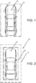
- flank refers, collectively, to the left and right surfaces of a vehicle, corresponding to the doors and side windows, as shown in FIG.1 , which includes the left flank 12 and the right flank 14 of the vehicle 10.
- FIG. 2 shows a virtual distance grid 16 surrounding the vehicle, including an outer boundary 18 and an inner boundary 20.
- the doorframe of the garage may intrude into the proximity of the left flank 12 ( FIG. 1 ) or the right flank 14 ( FIG. 1 ) of the vehicle and cause scratches and/or a dent.
- proximity sensor refers to a sensor that reports distance to an object/obstacle as an output, such as a sonar/ultrasound sensor, radar, lidar, etc.
- low-speed maneuvering refers to maneuvering under 10 mph.
- the present invention provides a vehicle system for displaying and detecting objects/obstacles in a flank of a vehicle, including: one or more cameras operable for obtaining one or more images of the flank of the vehicle; an algorithm operable for removing distortion from the one or more images, transforming the one or more images, and overlaying a virtual distance grid on the one or more images for presentation to an operator on a display disposed within the vehicle; means for detecting an object/obstacle within a predefined virtual safety envelope defined one or more of adjacent to and around the vehicle and including the flank of the vehicle; and a warning system operable for alerting the operator to the object/obstacle within the predefined virtual safety envelope defined one or more of adjacent to and around the vehicle and including the flank of the vehicle.
- Transforming the one or more images includes rotationally transforming the one or more images.
- the one or more images include a plurality of images each capturing a portion of the flank of the vehicle.
- the virtual distance grid is derived from at least one of a calibration parameter and a look-up table.
- the virtual distance grid includes at least one zone relatively closer to the vehicle and at least one zone relatively farther from the vehicle.
- the means for detecting the object/obstacle include one or more of the one or more cameras and a proximity sensor.
- the warning system includes one or more of a visual warning system, an auditory warning system, and a haptic warning system.
- the algorithm is further operable for determining and displaying one or more of a present orientation of the vehicle and a future orientation of the vehicle on the one or more images displayed to the operator.
- the algorithm is further operable for detecting and alerting the operator to a potential interaction between the object/obstacle and a door of the vehicle when open based on a predetermined or expected opening distance of the vehicle.
- the algorithm is further operable for detecting and predicting a potential incursion of a moving object/obstacle into the flank of the vehicle and alerting the operator thereto such that the operator does not unsafely exit the vehicle.
- the system further includes an illumination system operable for selectively illuminating the flank of the vehicle such that the one or more images can be obtained when one or more of: a low illumination condition is detected and the one or more cameras are activated.
- the present invention provides a vehicle method for displaying and detecting objects/obstacles in a flank of a vehicle, including: obtaining one or more images of the flank of the vehicle using one or more cameras; removing distortion from the one or more images, transforming the one or more images, and overlaying a virtual distance grid on the one or more images for presentation to an operator on a display disposed within the vehicle; detecting an object/obstacle within a predefined virtual safety envelope defined one or more of adjacent to and around the vehicle and including the flank of the vehicle; and alerting the operator to the object/obstacle within the predefined virtual safety envelope defined one or more of adjacent to and around the vehicle and including the flank of the vehicle using a warning system.
- Transforming the one or more images includes rotationally transforming the one or more images.
- the one or more images include a plurality of images each capturing a portion of the flank of the vehicle.
- the virtual distance grid is derived from at least one of a calibration parameter and a look-up table.
- the virtual distance grid includes at least one zone relatively closer to the vehicle and at least one zone relatively farther from the vehicle.
- the detecting the object/obstacle includes using one or more of the one or more cameras and a proximity sensor.
- the warning system includes one or more of a visual warning system, an auditory warning system, and a haptic warning system.
- the method further includes determining and displaying one or more of a present orientation of the vehicle and a future orientation of the vehicle on the one or more images displayed to the operator.
- the method further includes detecting and alerting the operator to a potential interaction between the object/obstacle and a door of the vehicle when open based on a predetermined or expected opening distance of the vehicle.
- the method further includes detecting and predicting a potential incursion of a moving object/obstacle into the flank of the vehicle and alerting the operator thereto such that the operator does not unsafely exit the vehicle.
- the method further includes selectively illuminating the flank of the vehicle such that the one or more images can be obtained when one or more of: a low illumination condition is detected and the one or more cameras are activated.
- the present invention provides a vehicle, including: one or more cameras operable for obtaining one or more images of the flank of the vehicle; an algorithm operable for removing distortion from the one or more images, transforming the one or more images, and overlaying a virtual distance grid on the one or more images for presentation to an operator on a display disposed within the vehicle; means for detecting an object/obstacle within a predefined virtual safety envelope defined one or more of adjacent to and around the vehicle and including a flank of the vehicle; and a warning system operable for alerting the operator to the object/obstacle within the predefined virtual safety envelope defined one or more of adjacent to and around the vehicle and including the flank of the vehicle.
- the means for detecting the object/obstacle include one or more of the one or more cameras and a proximity sensor.
- the present invention provides a DA system and method for vehicle flank safety.
- This system and method also have utility in AD applications.
- the system and method optionally pair one or more cameras with one or more proximity sensors to provide free space awareness and contact avoidance related to the flank of a vehicle, providing a virtual distance grid overlay on one or more camera views available to an operator, predefined safety boundary intrusion detection under low-speed maneuvering conditions, door-open obstruction and danger detection, and a flank illumination system.
- a virtual distance grid 16 ( FIG. 2 ) is overlaid on a flank-view camera display to provide visual assistance to an operator such that he or she has better distance/free space awareness.
- automatic proximity intrusion detection provides a warning when an object/obstacle falls within a predetermined distance from the vehicle 10 ( FIGS. 1 and 2 ), thereby providing enhanced collision avoidance under low-speed maneuvering conditions.
- operator information such as yaw and steering wheel angle, is used to display the current and predicted position and orientation of the vehicle 10, with the overlaid virtual distance grid 16, further enhancing collision avoidance under low-speed maneuvering conditions.
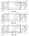
- flank camera images 22, 24, and 26 are provided and displayed to the operator after distortions are removed and rotational transformation or the like is performed.
- three sub-images 22, 24, and 26 are provided and displayed, including a front-wheel view 22, a side view 24, and a rear-wheel view 26, all proximate the near-flank 12 or 14 of the vehicle.
- BEVs bird's-eye-views
- the virtual distance grid 16 is overlaid on each of the sub-images 22, 24, and 26 using calibration parameters and/or look-up tables. Such techniques are well known to persons of ordinary skill in the art.
- the sub-images 22, 24, and 26 show an object/obstacle 28 outside of both the outer boundary 18 and the inner boundary 20 of the virtual distance grid 16, the object/obstacle 28 between the outer boundary 18 and the inner boundary 20 of the virtual distance grid 16, and the object/obstacle 28 inside both the outer boundary 18 and the inner boundary 20 of the virtual distance grid 16, respectively.
- the immediate next position of the vehicle 10 is predicted based on yaw angle, steering wheel angle, and the like, which information may also be displayed on the sub-mages 22, 24, and 26.
- FIGS. 4a-c shows an object/obstacle 28 outside of both the outer boundary 18 and the inner boundary 20 of the virtual distance grid 16, the object/obstacle 28 between the outer boundary 18 and the inner boundary 20 of the virtual distance grid 16, and the object/obstacle 28 inside both the outer boundary 18 and the inner boundary 20 of the virtual distance grid 16, respectively.
- the present invention utilizes obtained object/obstacle distance information, such as that related to nearby parked vehicles, combined with maximum door open angle information to alert an operator to potential impacts when a door is opened or the like.
- ground illumination may be provided when the cameras/proximity sensors of the present invention are activated.
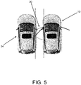
- door-open protection ensures the process of opening the door 30 without slamming it into other objects, such as nearby parked vehicles 34
- exit danger warning ensures the process of opening the door 30 and/or stepping out of the vehicle 10 without being hit by incoming moving objects, such as a vehicle or a cyclist 34 from the rear-flank.
- these functions could be activated and deactivated by manual instruction in a manner similar to how window/door locks in today's vehicles work, in order to prevent unwanted obstruction of the door 30.
- These functions should also be disabled in case a collision is detected, for example, when the airbag is activated, to prevent passengers from being locked in the vehicle while not able to manually deactivate them. It is recommended that these functions are only activated when the vehicle is parked (in P gear).
- the free space at the flanks are estimated based on algorithms that operate on data from the camera(s) and proximity sensor(s). Based on the estimated free space, the maximum door-open angle is calculated, such that the operational area of the door does not overlap with any non-free space.
- an extra layer of moving object detection is added besides the free space estimation.
- the nearby moving objects 34 are detected and tracked with the camera(s) and proximity sensors(s) using machine learning algorithms. Their speeds are estimated and the future trajectories are predicted. Once enabled, the system will calculate whether the operational area of door opening, as well as the (pre-defined) possible stepping out area 32 will be crossed by any of the trajectories of the nearby moving objects 34. If so, an appropriate alert is given.
- flank illumination is activated when at least the following two criteria are met simultaneously:
- the software application/algorithm/method of the present invention is implemented as coded instructions stored in a memory and executed by a processor.
- the processor is a hardware device for executing such coded instructions.
- the processor can be any custom made or commercially available processor, a central processing unit (CPU), an auxiliary processor among several processors associated with the memory, a semiconductor-based microprocessor (in the form of a microchip or chip set), or generally any device for executing coded instructions.
- the processor is configured to execute software stored within the memory, to communicate data to and from the memory, and to generally control operations pursuant to the coded instructions.
- the processor may include a mobile optimized processor, such as one optimized for power consumption and mobile applications.
- I/O interfaces can be used to receive user input and/or for providing system output.
- User input can be provided via, for example, a keypad, a touch screen, a scroll ball, a scroll bar, buttons, a voice-activation system, and/or the like.
- System output can be provided via a display device, such as a liquid crystal display (LCD), touch screen, and/or the like.
- the I/O interfaces can also include, for example, a serial port, a parallel port, a small computer system interface (SCSI), an infrared (IR) interface, a radio frequency (RF) interface, a universal serial bus (USB) interface, and/or the like.
- the I/O interfaces can include a graphical user interface (GUI) that enables the user to interact with the memory. Additionally, the I/O interfaces may further include an imaging device, i.e. the camera(s), etc.
- GUI graphical user interface
- the memory may include any of volatile memory elements (e.g., random access memory (RAM, such as DRAM, SRAM, SDRAM, etc.)), nonvolatile memory elements (e.g., ROM, hard drive, etc.), and combinations thereof. Moreover, the memory may incorporate electronic, magnetic, optical, and/or other types of storage media. Note that the memory may have a distributed architecture, where various components are situated remotely from one another, but can be accessed by the processor.
- the software in memory can include one or more software programs, each of which includes an ordered listing of executable instructions for implementing logical functions.
- the software in the memory includes a suitable operating system (O/S) and programs.
- O/S operating system
- the operating system essentially controls the execution of other computer programs, and provides scheduling, input-output control, file and data management, memory management, and communication control and related services.
- the programs may include various applications, add-ons, etc. configured to provide end user functionality.
- the programs can include an application or "app" which provides various functionalities.
- the present invention provides a DA system and method for vehicle flank safety.
- This system and method also have utility in AD applications.
- the system and method optionally pair one or more cameras with one or more proximity sensors to provide free space awareness and contact avoidance related to the flank of a vehicle, providing a virtual distance grid overlay on one or more camera views available to an operator, predefined safety boundary intrusion detection under low-speed maneuvering conditions, door-open obstruction and danger detection, and a flank illumination system.
Landscapes
- Engineering & Computer Science (AREA)
- Mechanical Engineering (AREA)
- Multimedia (AREA)
- Automation & Control Theory (AREA)
- Transportation (AREA)
- Human Computer Interaction (AREA)
- Physics & Mathematics (AREA)
- General Physics & Mathematics (AREA)
- Theoretical Computer Science (AREA)
- Traffic Control Systems (AREA)
- Closed-Circuit Television Systems (AREA)
- Fittings On The Vehicle Exterior For Carrying Loads, And Devices For Holding Or Mounting Articles (AREA)
Abstract
Description
- The present invention relates generally to the automotive and active safety fields. More specifically, the present invention relates to a driver assistance (DA) system and method for vehicle flank safety. This system and method also have utility in autonomous driving (AD) applications. The system and method optionally pair one or more cameras with one or more proximity sensors to provide free space awareness and contact avoidance related to the flank of a vehicle, providing a virtual distance grid overlay on one or more camera views available to an operator, predefined safety boundary intrusion detection under low-speed maneuvering conditions, door-open obstruction and danger detection, and a flank illumination system.
- The use of cameras to obtain surrounding views of a vehicle is well known to persons of ordinary skill in the art. It is also well known to persons of ordinary skill in the art to provide a virtual distance grid overlay on a rear camera view available to an operator when backing up a vehicle. It is further well known to persons of ordinary skill in the art to detect objects and obstacles within a predefined safety boundary in front of and/or behind a vehicle using proximity sensors, such as sonar, radar, and/or lidar. However, such proximity sensors are typically mounted near the corner of a vehicle and do not provide full flank coverage.
- Thus, an object of the present invention is to provide 360-degree visual assistance to the operator of a vehicle, especially with respect to the flank of a vehicle, as well as predefined safety boundary intrusion detection to the flank of the vehicle under low-speed maneuvering conditions - with either a camera only or a camera-proximity sensor combination. An object of the present invention is also to use this predefined flank safety boundary to assess the safety of opening a door in a given situation, given the detected presence/absence of a stationary or approaching object or obstacle. An object of the present invention is further to provide or trigger flank illumination under given circumstances, such that flank visibility and imaging is improved.
- In various aspects, the present invention provides a DA system and method for vehicle flank safety. This system and method also have utility in AD applications. The system and method optionally pair one or more cameras with one or more proximity sensors to provide free space awareness and contact avoidance related to the flank of a vehicle, providing a virtual distance grid overlay on one or more camera views available to an operator, predefined safety boundary intrusion detection under low-speed maneuvering conditions, door-open obstruction and danger detection, and a flank illumination system.
- As used herein, "flank" refers, collectively, to the left and right surfaces of a vehicle, corresponding to the doors and side windows, as shown in
FIG.1 , which includes theleft flank 12 and theright flank 14 of thevehicle 10. - As used herein, "proximity intrusion" refers to situations in which objects/obstacles fall within a predetermined safety envelope surrounding the
vehicle 10, which may cause undesired contact and collision with thevehicle 10.FIG. 2 shows avirtual distance grid 16 surrounding the vehicle, including anouter boundary 18 and aninner boundary 20. For example, when parking in a narrow garage, the doorframe of the garage may intrude into the proximity of the left flank 12 (FIG. 1 ) or the right flank 14 (FIG. 1 ) of the vehicle and cause scratches and/or a dent. - As used herein, "proximity sensor" refers to a sensor that reports distance to an object/obstacle as an output, such as a sonar/ultrasound sensor, radar, lidar, etc.
- As used herein, "low-speed maneuvering" refers to maneuvering under 10 mph.
- In one specific aspect, the present invention provides a vehicle system for displaying and detecting objects/obstacles in a flank of a vehicle, including: one or more cameras operable for obtaining one or more images of the flank of the vehicle; an algorithm operable for removing distortion from the one or more images, transforming the one or more images, and overlaying a virtual distance grid on the one or more images for presentation to an operator on a display disposed within the vehicle; means for detecting an object/obstacle within a predefined virtual safety envelope defined one or more of adjacent to and around the vehicle and including the flank of the vehicle; and a warning system operable for alerting the operator to the object/obstacle within the predefined virtual safety envelope defined one or more of adjacent to and around the vehicle and including the flank of the vehicle. Transforming the one or more images includes rotationally transforming the one or more images. Optionally, the one or more images include a plurality of images each capturing a portion of the flank of the vehicle. The virtual distance grid is derived from at least one of a calibration parameter and a look-up table. The virtual distance grid includes at least one zone relatively closer to the vehicle and at least one zone relatively farther from the vehicle. The means for detecting the object/obstacle include one or more of the one or more cameras and a proximity sensor. The warning system includes one or more of a visual warning system, an auditory warning system, and a haptic warning system. The algorithm is further operable for determining and displaying one or more of a present orientation of the vehicle and a future orientation of the vehicle on the one or more images displayed to the operator. The algorithm is further operable for detecting and alerting the operator to a potential interaction between the object/obstacle and a door of the vehicle when open based on a predetermined or expected opening distance of the vehicle. The algorithm is further operable for detecting and predicting a potential incursion of a moving object/obstacle into the flank of the vehicle and alerting the operator thereto such that the operator does not unsafely exit the vehicle. The system further includes an illumination system operable for selectively illuminating the flank of the vehicle such that the one or more images can be obtained when one or more of: a low illumination condition is detected and the one or more cameras are activated.
- In another specific aspect, the present invention provides a vehicle method for displaying and detecting objects/obstacles in a flank of a vehicle, including: obtaining one or more images of the flank of the vehicle using one or more cameras; removing distortion from the one or more images, transforming the one or more images, and overlaying a virtual distance grid on the one or more images for presentation to an operator on a display disposed within the vehicle; detecting an object/obstacle within a predefined virtual safety envelope defined one or more of adjacent to and around the vehicle and including the flank of the vehicle; and alerting the operator to the object/obstacle within the predefined virtual safety envelope defined one or more of adjacent to and around the vehicle and including the flank of the vehicle using a warning system. Transforming the one or more images includes rotationally transforming the one or more images. Optionally, the one or more images include a plurality of images each capturing a portion of the flank of the vehicle. The virtual distance grid is derived from at least one of a calibration parameter and a look-up table. The virtual distance grid includes at least one zone relatively closer to the vehicle and at least one zone relatively farther from the vehicle. The detecting the object/obstacle includes using one or more of the one or more cameras and a proximity sensor. The warning system includes one or more of a visual warning system, an auditory warning system, and a haptic warning system. The method further includes determining and displaying one or more of a present orientation of the vehicle and a future orientation of the vehicle on the one or more images displayed to the operator. The method further includes detecting and alerting the operator to a potential interaction between the object/obstacle and a door of the vehicle when open based on a predetermined or expected opening distance of the vehicle. The method further includes detecting and predicting a potential incursion of a moving object/obstacle into the flank of the vehicle and alerting the operator thereto such that the operator does not unsafely exit the vehicle. The method further includes selectively illuminating the flank of the vehicle such that the one or more images can be obtained when one or more of: a low illumination condition is detected and the one or more cameras are activated.
- In a further specific aspect, the present invention provides a vehicle, including: one or more cameras operable for obtaining one or more images of the flank of the vehicle; an algorithm operable for removing distortion from the one or more images, transforming the one or more images, and overlaying a virtual distance grid on the one or more images for presentation to an operator on a display disposed within the vehicle; means for detecting an object/obstacle within a predefined virtual safety envelope defined one or more of adjacent to and around the vehicle and including a flank of the vehicle; and a warning system operable for alerting the operator to the object/obstacle within the predefined virtual safety envelope defined one or more of adjacent to and around the vehicle and including the flank of the vehicle. The means for detecting the object/obstacle include one or more of the one or more cameras and a proximity sensor.
- The present invention is illustrated and described herein with reference to the various drawings, in which like reference numbers are used to denote like system components/method steps, as appropriate, and in which:
-
FIG. 1 is a schematic view illustrating the left flank and the right flank of a vehicle, both covered by the system and method of the present invention; -
FIG. 2 is a schematic view illustrating a virtual distance grid around the vehicle, used to trigger the proximity intrusion detection warning of the present invention; -
FIGS. 3a-c are schematic views illustrating exemplary flank camera views overlaid with a virtual distance grid in accordance with the system and method of the present invention; -
FIGS. 4a-c are schematic views illustrating the intrusion of an object/obstacle into the predetermined safety margin surrounding the vehicle, thereby potentially causing damage to the vehicle; -
FIG. 5 is a schematic view illustrating the functionality of the door impact warning system of the present invention; and -
FIG. 6 is a schematic view illustrating the functionality of the exit danger warning system of the present invention. - Again, in various aspects, the present invention provides a DA system and method for vehicle flank safety. This system and method also have utility in AD applications. The system and method optionally pair one or more cameras with one or more proximity sensors to provide free space awareness and contact avoidance related to the flank of a vehicle, providing a virtual distance grid overlay on one or more camera views available to an operator, predefined safety boundary intrusion detection under low-speed maneuvering conditions, door-open obstruction and danger detection, and a flank illumination system.
- The system and method of the present invention perform three primary functions. First, a virtual distance grid 16 (
FIG. 2 ) is overlaid on a flank-view camera display to provide visual assistance to an operator such that he or she has better distance/free space awareness. Second, automatic proximity intrusion detection provides a warning when an object/obstacle falls within a predetermined distance from the vehicle 10 (FIGS. 1 and 2 ), thereby providing enhanced collision avoidance under low-speed maneuvering conditions. Third, operator information, such as yaw and steering wheel angle, is used to display the current and predicted position and orientation of thevehicle 10, with the overlaidvirtual distance grid 16, further enhancing collision avoidance under low-speed maneuvering conditions. - Referring now specifically to
FIGS. 2 and3a-c , in accordance with the system and method of the present invention, one or moreflank camera images wheel view 22, aside view 24, and a rear-wheel view 26, all proximate the near-flank virtual distance grid 16 is overlaid on each of the sub-images 22, 24, and 26 using calibration parameters and/or look-up tables. Such techniques are well known to persons of ordinary skill in the art. Here, the sub-images 22, 24, and 26 show an object/obstacle 28 outside of both theouter boundary 18 and theinner boundary 20 of thevirtual distance grid 16, the object/obstacle 28 between theouter boundary 18 and theinner boundary 20 of thevirtual distance grid 16, and the object/obstacle 28 inside both theouter boundary 18 and theinner boundary 20 of thevirtual distance grid 16, respectively. The immediate next position of thevehicle 10 is predicted based on yaw angle, steering wheel angle, and the like, which information may also be displayed on the sub-mages 22, 24, and 26. - As is done conventionally for back-up maneuvering, algorithms are used in conjunction with the camera(s) and/or proximity sensor(s) to detect/predict intrusions into the
virtual distance grid 16.FIGS. 4a-c shows an object/obstacle 28 outside of both theouter boundary 18 and theinner boundary 20 of thevirtual distance grid 16, the object/obstacle 28 between theouter boundary 18 and theinner boundary 20 of thevirtual distance grid 16, and the object/obstacle 28 inside both theouter boundary 18 and theinner boundary 20 of thevirtual distance grid 16, respectively. The present invention utilizes obtained object/obstacle distance information, such as that related to nearby parked vehicles, combined with maximum door open angle information to alert an operator to potential impacts when a door is opened or the like. Similarly, the operator may be warned of moving vehicles, bicycles, pedestrians, etc. approaching the near-flank 12 and 14 (FIG. 1 ) of thevehicle 10. Finally, suitable ground illumination may be provided when the cameras/proximity sensors of the present invention are activated. - Referring now specifically to
FIGS. 5 and6 , the protection associated with exiting avehicle 10 is two-fold: (1) door-open protection and (2) exit danger warning. Broadly speaking, door-open protection ensures the process of opening thedoor 30 without slamming it into other objects, such as nearby parkedvehicles 34, and exit danger warning ensures the process of opening thedoor 30 and/or stepping out of thevehicle 10 without being hit by incoming moving objects, such as a vehicle or acyclist 34 from the rear-flank. These two functions are closely related as they both affect when it is safe to open thedoor 30 and step out of thevehicle 10, and how much thedoor 30 be opened safely. - It should be emphasized that these functions could be activated and deactivated by manual instruction in a manner similar to how window/door locks in today's vehicles work, in order to prevent unwanted obstruction of the
door 30. These functions should also be disabled in case a collision is detected, for example, when the airbag is activated, to prevent passengers from being locked in the vehicle while not able to manually deactivate them. It is recommended that these functions are only activated when the vehicle is parked (in P gear). - Once enabled, the free space at the flanks are estimated based on algorithms that operate on data from the camera(s) and proximity sensor(s). Based on the estimated free space, the maximum door-open angle is calculated, such that the operational area of the door does not overlap with any non-free space.
- For the exit danger warning, an extra layer of moving object detection is added besides the free space estimation. The nearby moving
objects 34 are detected and tracked with the camera(s) and proximity sensors(s) using machine learning algorithms. Their speeds are estimated and the future trajectories are predicted. Once enabled, the system will calculate whether the operational area of door opening, as well as the (pre-defined) possible stepping outarea 32 will be crossed by any of the trajectories of the nearby moving objects 34. If so, an appropriate alert is given. - Many conventional vehicles have surrounding illuminations for aesthetic purposes. Many safety features, especially ones require the use of camera(s), will not work ideally without proper illumination. For example, camera-based parking line detection, lane detection, object detection, as well as the applications currently being described would benefit from added illumination. In order to make vehicles safe in both day time and night time conditions, both outdoor and indoor, flank illumination is thus important. To save energy, flank illumination should not be activated all the time. In the present invention, flank illumination is activated when at least the following two criteria are met simultaneously:
- 1. Low illumination is detected. For this, the same technology as automatic headlights is utilized.
- 2. Surround/flank cameras are activated. This could be either manually or automatically triggered by other features in the vehicle.
- Preferably, the software application/algorithm/method of the present invention is implemented as coded instructions stored in a memory and executed by a processor. The processor is a hardware device for executing such coded instructions. The processor can be any custom made or commercially available processor, a central processing unit (CPU), an auxiliary processor among several processors associated with the memory, a semiconductor-based microprocessor (in the form of a microchip or chip set), or generally any device for executing coded instructions. The processor is configured to execute software stored within the memory, to communicate data to and from the memory, and to generally control operations pursuant to the coded instructions. In an exemplary embodiment, the processor may include a mobile optimized processor, such as one optimized for power consumption and mobile applications. Input/output (I/O) interfaces can be used to receive user input and/or for providing system output. User input can be provided via, for example, a keypad, a touch screen, a scroll ball, a scroll bar, buttons, a voice-activation system, and/or the like. System output can be provided via a display device, such as a liquid crystal display (LCD), touch screen, and/or the like. The I/O interfaces can also include, for example, a serial port, a parallel port, a small computer system interface (SCSI), an infrared (IR) interface, a radio frequency (RF) interface, a universal serial bus (USB) interface, and/or the like. The I/O interfaces can include a graphical user interface (GUI) that enables the user to interact with the memory. Additionally, the I/O interfaces may further include an imaging device, i.e. the camera(s), etc.
- The memory may include any of volatile memory elements (e.g., random access memory (RAM, such as DRAM, SRAM, SDRAM, etc.)), nonvolatile memory elements (e.g., ROM, hard drive, etc.), and combinations thereof. Moreover, the memory may incorporate electronic, magnetic, optical, and/or other types of storage media. Note that the memory may have a distributed architecture, where various components are situated remotely from one another, but can be accessed by the processor. The software in memory can include one or more software programs, each of which includes an ordered listing of executable instructions for implementing logical functions. The software in the memory includes a suitable operating system (O/S) and programs. The operating system essentially controls the execution of other computer programs, and provides scheduling, input-output control, file and data management, memory management, and communication control and related services. The programs may include various applications, add-ons, etc. configured to provide end user functionality. The programs can include an application or "app" which provides various functionalities.
- Thus, in various aspects, the present invention provides a DA system and method for vehicle flank safety. This system and method also have utility in AD applications. The system and method optionally pair one or more cameras with one or more proximity sensors to provide free space awareness and contact avoidance related to the flank of a vehicle, providing a virtual distance grid overlay on one or more camera views available to an operator, predefined safety boundary intrusion detection under low-speed maneuvering conditions, door-open obstruction and danger detection, and a flank illumination system.
- Although the present invention is illustrated and described herein with reference to preferred embodiments and specific examples thereof, it will be readily apparent to persons of ordinary skill in the art that other embodiments and examples may perform similar functions and/or achieve like results. All such equivalent embodiments and examples are within the spirit and scope of the present invention, are contemplated thereby, and are intended to be covered by the following non-limiting claims for all purposes.
Claims (15)
- A vehicle system for displaying and detecting objects/obstacles in a flank of a vehicle, comprising:one or more cameras operable for obtaining one or more images of the flank of the vehicle;an algorithm operable for removing distortion from the one or more images, transforming the one or more images, and overlaying a virtual distance grid on the one or more images on a display in the vehicle;means for detecting an object/obstacle within a predefined virtual safety envelope defined one or more of adjacent to and around the vehicle, wherein the means for detecting the object/obstacle comprise one or more of the one or more cameras and a proximity sensor; anda warning system operable for alerting the operator to the object/obstacle within the predefined virtual safety envelope defined one or more of adjacent to and around the vehicle.
- The vehicle system of claim 1, wherein transforming the one or more images comprises rotationally transforming the one or more images.
- The vehicle system of claim 1, wherein the one or more images comprise a plurality of images each capturing a portion of the flank of the vehicle.
- The vehicle system of claim 1, wherein the virtual distance grid is derived from at least one of a calibration parameter and a look-up table, and wherein the virtual distance grid comprises at least one zone relatively closer to the vehicle and at least one zone relatively farther from the vehicle.
- The vehicle system of claim 1, wherein the algorithm is further operable for determining and displaying one or more of a present orientation of the vehicle and a future orientation of the vehicle on the one or more images displayed to the operator.
- The vehicle system of claim 1, wherein the algorithm is further operable for detecting and alerting the operator to a potential interaction between the object/obstacle and a door of the vehicle when open based on a predetermined or expected opening distance of the vehicle.
- The vehicle system of claim 1, wherein the algorithm is further operable for detecting and predicting a potential incursion of a moving object/obstacle into the flank of the vehicle and alerting the operator.
- The vehicle system of claim 1, further comprising an illumination system operable for selectively illuminating the flank of the vehicle such that the one or more images can be obtained when one or more of: a low illumination condition is detected and the one or more cameras are activated.
- A vehicle method for displaying and detecting objects/obstacles in a flank of a vehicle, comprising:obtaining one or more images of the flank of the vehicle using one or more cameras;removing distortion from the one or more images, transforming the one or more images, and overlaying a virtual distance grid on the one or more images on a display in the vehicle;detecting an object/obstacle within a predefined virtual safety envelope defined one or more of adjacent to and around the vehicle, wherein the detecting the object/obstacle comprises using one or more of the one or more cameras and a proximity sensor; andalerting the operator to the object/obstacle within the predefined virtual safety envelope defined one or more of adjacent to and around the vehicle using a warning system.
- The vehicle method of claim 9, wherein transforming the one or more images comprises rotationally transforming the one or more images.
- The vehicle method of claim 9, wherein the one or more images comprise a plurality of images each capturing a portion of the flank of the vehicle.
- The vehicle method of claim 9, wherein the virtual distance grid is derived from at least one of a calibration parameter and a look-up table, and wherein the virtual distance grid comprises at least one zone relatively closer to the vehicle and at least one zone relatively farther from the vehicle.
- The vehicle method of claim 9, further comprising determining and displaying one or more of a present orientation of the vehicle and a future orientation of the vehicle on the one or more images displayed to the operator.
- The vehicle method of claim 9, further comprising detecting and alerting the operator to a potential interaction between the object/obstacle and a door of the vehicle when open based on a predetermined or expected opening distance of the vehicle.
- The vehicle method of claim 9, further comprising detecting and predicting a potential incursion of a moving object/obstacle into the flank of the vehicle and alerting the operator.
Applications Claiming Priority (1)
| Application Number | Priority Date | Filing Date | Title |
|---|---|---|---|
| US201862727270P | 2018-09-05 | 2018-09-05 |
Publications (2)
| Publication Number | Publication Date |
|---|---|
| EP3620332A1 true EP3620332A1 (en) | 2020-03-11 |
| EP3620332B1 EP3620332B1 (en) | 2021-03-10 |
Family
ID=67847657
Family Applications (1)
| Application Number | Title | Priority Date | Filing Date |
|---|---|---|---|
| EP19195141.7A Active EP3620332B1 (en) | 2018-09-05 | 2019-09-03 | Driver assistance system and method for vehicle flank safety |
Country Status (2)
| Country | Link |
|---|---|
| US (1) | US11787334B2 (en) |
| EP (1) | EP3620332B1 (en) |
Cited By (2)
| Publication number | Priority date | Publication date | Assignee | Title |
|---|---|---|---|---|
| EP4086116A1 (en) * | 2021-05-07 | 2022-11-09 | Guangzhou Xiaopeng Motors Technology Co., Ltd. | Vehicle door-opening anti-collision method and apparatus, vehicle, and storage medium |
| GB2609767A (en) * | 2019-08-29 | 2023-02-15 | Motional Ad Llc | Methods for passenger authentication and door operation for autonomous vehicles |
Families Citing this family (11)
| Publication number | Priority date | Publication date | Assignee | Title |
|---|---|---|---|---|
| US9557736B1 (en) * | 2015-04-08 | 2017-01-31 | Google Inc. | Detecting street parked vehicles |
| EP3620332B1 (en) * | 2018-09-05 | 2021-03-10 | Volvo Car Corporation | Driver assistance system and method for vehicle flank safety |
| US11443517B1 (en) * | 2019-08-19 | 2022-09-13 | Alarm.Com Incorporated | Video-based parking garage monitoring |
| US11351998B2 (en) * | 2020-03-18 | 2022-06-07 | Denso Corporation | Systems and methods for adapting activation of alerts according to curvature of a target path |
| BR112022025423A2 (en) * | 2020-06-19 | 2023-01-24 | Stoneridge Electronics Ab | MAN-MACHINE INTERFACE FOR COMMERCIAL VEHICLE CAMERA SYSTEMS |
| DE102020129844A1 (en) * | 2020-11-12 | 2022-05-12 | Kiekert Aktiengesellschaft | Method and device for controlling at least one motor vehicle closure element |
| US11724643B2 (en) * | 2021-01-20 | 2023-08-15 | Ford Global Technologies, Llc | Vehicle alarm |
| JP7671632B2 (en) * | 2021-06-22 | 2025-05-02 | フォルシアクラリオン・エレクトロニクス株式会社 | Vehicle surrounding information display device and vehicle surrounding information display method |
| US12306005B2 (en) * | 2021-07-23 | 2025-05-20 | Magna Electronics Inc. | Vehicular vision system with reduced memory for adaptable graphic overlays |
| KR20230151141A (en) * | 2022-04-22 | 2023-11-01 | 현대자동차주식회사 | Device for assisting safety exit of vehicle and method therefor |
| US12221036B2 (en) | 2022-10-05 | 2025-02-11 | Ford Global Technologies, Llc | Trailer sideswipe avoidance system |
Citations (6)
| Publication number | Priority date | Publication date | Assignee | Title |
|---|---|---|---|---|
| DE10226278A1 (en) * | 2002-06-13 | 2003-12-24 | Peter Lux | Collision avoidance system for helping a driver driving backwards comprises a rear-directed video camera, illumination source for generating a pattern and evaluation unit for deriving position information from the pattern image |
| US20090259401A1 (en) * | 2008-04-15 | 2009-10-15 | Caterpillar Inc. | Vehicle collision avoidance system |
| FR2982552A1 (en) * | 2011-11-10 | 2013-05-17 | Denso Corp | Monitoring device for monitoring e.g. motor bike in perimeter of object vehicle, has synthesis image generator producing display of information according to movement detection result, and display device displaying image and information |
| US20130155240A1 (en) * | 2011-06-07 | 2013-06-20 | Komatsu Ltd. | Work vehicle periphery monitoring apparatus |
| US20160001701A1 (en) * | 2014-07-03 | 2016-01-07 | Topcon Positioning Systems, Inc. | Machine Safety Dome |
| WO2016178190A1 (en) * | 2015-05-06 | 2016-11-10 | Magna Mirrors Of America, Inc. | Vehicle vision system with blind zone display and alert system |
Family Cites Families (22)
| Publication number | Priority date | Publication date | Assignee | Title |
|---|---|---|---|---|
| US5670935A (en) | 1993-02-26 | 1997-09-23 | Donnelly Corporation | Rearview vision system for vehicle including panoramic view |
| US5550677A (en) | 1993-02-26 | 1996-08-27 | Donnelly Corporation | Automatic rearview mirror system using a photosensor array |
| EP1179958B1 (en) * | 1999-04-16 | 2012-08-08 | Panasonic Corporation | Image processing device and monitoring system |
| US7167796B2 (en) | 2000-03-09 | 2007-01-23 | Donnelly Corporation | Vehicle navigation system for use with a telematics system |
| US7720580B2 (en) * | 2004-12-23 | 2010-05-18 | Donnelly Corporation | Object detection system for vehicle |
| US20100194861A1 (en) * | 2009-01-30 | 2010-08-05 | Reuben Hoppenstein | Advance in Transmission and Display of Multi-Dimensional Images for Digital Monitors and Television Receivers using a virtual lens |
| WO2011154987A1 (en) * | 2010-06-07 | 2011-12-15 | 三菱電機株式会社 | Camera distance measurement device |
| WO2013109869A1 (en) * | 2012-01-20 | 2013-07-25 | Magna Electronics, Inc. | Vehicle vision system with free positional virtual panoramic view |
| JP5829980B2 (en) * | 2012-06-19 | 2015-12-09 | トヨタ自動車株式会社 | Roadside detection device |
| US20150077560A1 (en) * | 2013-03-22 | 2015-03-19 | GM Global Technology Operations LLC | Front curb viewing system based upon dual cameras |
| US20150009010A1 (en) * | 2013-07-03 | 2015-01-08 | Magna Electronics Inc. | Vehicle vision system with driver detection |
| US9359009B2 (en) * | 2014-03-22 | 2016-06-07 | Ford Global Technologies, Llc | Object detection during vehicle parking |
| US10525883B2 (en) * | 2014-06-13 | 2020-01-07 | Magna Electronics Inc. | Vehicle vision system with panoramic view |
| DE102014109062A1 (en) * | 2014-06-27 | 2015-12-31 | Connaught Electronics Ltd. | Method for tracking a target vehicle approaching a motor vehicle by means of a camera system of the motor vehicle, camera system and motor vehicle |
| JP6514624B2 (en) | 2015-11-02 | 2019-05-15 | クラリオン株式会社 | Obstacle detection device |
| EP3742725B1 (en) * | 2015-11-30 | 2024-03-20 | Sumitomo Heavy Industries, Ltd. | Surroundings monitoring system for work machine |
| DE102016201304A1 (en) * | 2016-01-28 | 2017-08-03 | Robert Bosch Gmbh | Apparatus and method for detecting a curb in an environment of a vehicle and curb control system for a vehicle |
| US9987983B2 (en) * | 2016-02-11 | 2018-06-05 | GM Global Technology Operations LLC | Parking assist system for a vehicle and method of using the same |
| JP6361986B2 (en) * | 2016-05-30 | 2018-07-25 | マツダ株式会社 | Vehicle display device |
| US10007854B2 (en) * | 2016-07-07 | 2018-06-26 | Ants Technology (Hk) Limited | Computer vision based driver assistance devices, systems, methods and associated computer executable code |
| US10313584B2 (en) * | 2017-01-04 | 2019-06-04 | Texas Instruments Incorporated | Rear-stitched view panorama for rear-view visualization |
| EP3620332B1 (en) * | 2018-09-05 | 2021-03-10 | Volvo Car Corporation | Driver assistance system and method for vehicle flank safety |
-
2019
- 2019-09-03 EP EP19195141.7A patent/EP3620332B1/en active Active
- 2019-09-04 US US16/559,820 patent/US11787334B2/en active Active
Patent Citations (6)
| Publication number | Priority date | Publication date | Assignee | Title |
|---|---|---|---|---|
| DE10226278A1 (en) * | 2002-06-13 | 2003-12-24 | Peter Lux | Collision avoidance system for helping a driver driving backwards comprises a rear-directed video camera, illumination source for generating a pattern and evaluation unit for deriving position information from the pattern image |
| US20090259401A1 (en) * | 2008-04-15 | 2009-10-15 | Caterpillar Inc. | Vehicle collision avoidance system |
| US20130155240A1 (en) * | 2011-06-07 | 2013-06-20 | Komatsu Ltd. | Work vehicle periphery monitoring apparatus |
| FR2982552A1 (en) * | 2011-11-10 | 2013-05-17 | Denso Corp | Monitoring device for monitoring e.g. motor bike in perimeter of object vehicle, has synthesis image generator producing display of information according to movement detection result, and display device displaying image and information |
| US20160001701A1 (en) * | 2014-07-03 | 2016-01-07 | Topcon Positioning Systems, Inc. | Machine Safety Dome |
| WO2016178190A1 (en) * | 2015-05-06 | 2016-11-10 | Magna Mirrors Of America, Inc. | Vehicle vision system with blind zone display and alert system |
Cited By (5)
| Publication number | Priority date | Publication date | Assignee | Title |
|---|---|---|---|---|
| GB2609767A (en) * | 2019-08-29 | 2023-02-15 | Motional Ad Llc | Methods for passenger authentication and door operation for autonomous vehicles |
| US11623611B2 (en) | 2019-08-29 | 2023-04-11 | Motional Ad Llc | Methods for passenger authentication and door operation for autonomous vehicles |
| GB2609767B (en) * | 2019-08-29 | 2023-06-21 | Motional Ad Llc | Methods for passenger authentication and door operation for autonomous vehicles |
| US12280740B2 (en) | 2019-08-29 | 2025-04-22 | Motional Ad Llc | Methods for passenger authentication and door operation for autonomous vehicles |
| EP4086116A1 (en) * | 2021-05-07 | 2022-11-09 | Guangzhou Xiaopeng Motors Technology Co., Ltd. | Vehicle door-opening anti-collision method and apparatus, vehicle, and storage medium |
Also Published As
| Publication number | Publication date |
|---|---|
| US11787334B2 (en) | 2023-10-17 |
| US20200070725A1 (en) | 2020-03-05 |
| EP3620332B1 (en) | 2021-03-10 |
Similar Documents
| Publication | Publication Date | Title |
|---|---|---|
| US11787334B2 (en) | Driver assistance system and method for vehicle flank safety | |
| US10586226B2 (en) | Integration of vehicle boundary alert system with external transaction equipment | |
| US8120476B2 (en) | Digital camera rear-view system | |
| US9725040B2 (en) | Vehicle object detection system | |
| US11261642B2 (en) | System and method for tracking moving objects to avoid interference with vehicular door operations | |
| EP3959104B1 (en) | Anti-collision warning system for vehicle door, vehicle window glass structure, and anti-collision warning method for vehicle door | |
| US10913393B2 (en) | Door opening clearance detection | |
| US20140098230A1 (en) | Blind zone detection and alert system for vehicle | |
| CN111071246A (en) | Vehicle parking assist for avoiding contact with garage door | |
| CN109313859B (en) | Method and obstacle assistance device for automatic activation of an obstacle recognition device of a motor vehicle | |
| CN107848465A (en) | Vehicle Vision System with Blind Spot Display and Warning System | |
| US9129495B1 (en) | Multi-purpose side camera | |
| CN111655540B (en) | Method for identifying at least one object in proximity to a motor vehicle | |
| US20180162274A1 (en) | Vehicle side-rear warning device and method using the same | |
| CN105015413A (en) | Blind-area monitoring system for vehicles, and control method of blind-area monitoring system | |
| CN114435244A (en) | A vehicle door switch obstacle detection method, device, device and medium | |
| EP4371822A1 (en) | Auxiliary driving system and vehicle | |
| CN204250041U (en) | A kind of panorama automated parking system | |
| JP4901326B2 (en) | Rear warning system using vehicle outside mirror | |
| US12243451B2 (en) | Apparatus for displaying at least one virtual lane line based on environmental condition and method of controlling same | |
| JP6617462B2 (en) | Vehicle periphery visual recognition device | |
| JPS62273477A (en) | Monitor for surrounding area of vehicle | |
| KR20170070608A (en) | Vehicle And Control Method Thereof | |
| CN118289023A (en) | Vehicle control method, device, equipment and storage medium | |
| CN117657193B (en) | Vehicle warning method, device, system and computer-readable storage medium |
Legal Events
| Date | Code | Title | Description |
|---|---|---|---|
| PUAI | Public reference made under article 153(3) epc to a published international application that has entered the european phase |
Free format text: ORIGINAL CODE: 0009012 |
|
| STAA | Information on the status of an ep patent application or granted ep patent |
Free format text: STATUS: THE APPLICATION HAS BEEN PUBLISHED |
|
| AK | Designated contracting states |
Kind code of ref document: A1 Designated state(s): AL AT BE BG CH CY CZ DE DK EE ES FI FR GB GR HR HU IE IS IT LI LT LU LV MC MK MT NL NO PL PT RO RS SE SI SK SM TR |
|
| AX | Request for extension of the european patent |
Extension state: BA ME |
|
| STAA | Information on the status of an ep patent application or granted ep patent |
Free format text: STATUS: REQUEST FOR EXAMINATION WAS MADE |
|
| 17P | Request for examination filed |
Effective date: 20200911 |
|
| RBV | Designated contracting states (corrected) |
Designated state(s): AL AT BE BG CH CY CZ DE DK EE ES FI FR GB GR HR HU IE IS IT LI LT LU LV MC MK MT NL NO PL PT RO RS SE SI SK SM TR |
|
| GRAP | Despatch of communication of intention to grant a patent |
Free format text: ORIGINAL CODE: EPIDOSNIGR1 |
|
| STAA | Information on the status of an ep patent application or granted ep patent |
Free format text: STATUS: GRANT OF PATENT IS INTENDED |
|
| INTG | Intention to grant announced |
Effective date: 20201029 |
|
| GRAS | Grant fee paid |
Free format text: ORIGINAL CODE: EPIDOSNIGR3 |
|
| GRAA | (expected) grant |
Free format text: ORIGINAL CODE: 0009210 |
|
| STAA | Information on the status of an ep patent application or granted ep patent |
Free format text: STATUS: THE PATENT HAS BEEN GRANTED |
|
| AK | Designated contracting states |
Kind code of ref document: B1 Designated state(s): AL AT BE BG CH CY CZ DE DK EE ES FI FR GB GR HR HU IE IS IT LI LT LU LV MC MK MT NL NO PL PT RO RS SE SI SK SM TR |
|
| REG | Reference to a national code |
Ref country code: GB Ref legal event code: FG4D |
|
| REG | Reference to a national code |
Ref country code: CH Ref legal event code: EP Ref country code: AT Ref legal event code: REF Ref document number: 1369489 Country of ref document: AT Kind code of ref document: T Effective date: 20210315 |
|
| REG | Reference to a national code |
Ref country code: IE Ref legal event code: FG4D |
|
| REG | Reference to a national code |
Ref country code: DE Ref legal event code: R096 Ref document number: 602019003091 Country of ref document: DE |
|
| REG | Reference to a national code |
Ref country code: LT Ref legal event code: MG9D |
|
| PG25 | Lapsed in a contracting state [announced via postgrant information from national office to epo] |
Ref country code: GR Free format text: LAPSE BECAUSE OF FAILURE TO SUBMIT A TRANSLATION OF THE DESCRIPTION OR TO PAY THE FEE WITHIN THE PRESCRIBED TIME-LIMIT Effective date: 20210611 Ref country code: FI Free format text: LAPSE BECAUSE OF FAILURE TO SUBMIT A TRANSLATION OF THE DESCRIPTION OR TO PAY THE FEE WITHIN THE PRESCRIBED TIME-LIMIT Effective date: 20210310 Ref country code: HR Free format text: LAPSE BECAUSE OF FAILURE TO SUBMIT A TRANSLATION OF THE DESCRIPTION OR TO PAY THE FEE WITHIN THE PRESCRIBED TIME-LIMIT Effective date: 20210310 Ref country code: BG Free format text: LAPSE BECAUSE OF FAILURE TO SUBMIT A TRANSLATION OF THE DESCRIPTION OR TO PAY THE FEE WITHIN THE PRESCRIBED TIME-LIMIT Effective date: 20210610 Ref country code: LT Free format text: LAPSE BECAUSE OF FAILURE TO SUBMIT A TRANSLATION OF THE DESCRIPTION OR TO PAY THE FEE WITHIN THE PRESCRIBED TIME-LIMIT Effective date: 20210310 Ref country code: NO Free format text: LAPSE BECAUSE OF FAILURE TO SUBMIT A TRANSLATION OF THE DESCRIPTION OR TO PAY THE FEE WITHIN THE PRESCRIBED TIME-LIMIT Effective date: 20210610 |
|
| REG | Reference to a national code |
Ref country code: AT Ref legal event code: MK05 Ref document number: 1369489 Country of ref document: AT Kind code of ref document: T Effective date: 20210310 |
|
| REG | Reference to a national code |
Ref country code: NL Ref legal event code: MP Effective date: 20210310 |
|
| PG25 | Lapsed in a contracting state [announced via postgrant information from national office to epo] |
Ref country code: LV Free format text: LAPSE BECAUSE OF FAILURE TO SUBMIT A TRANSLATION OF THE DESCRIPTION OR TO PAY THE FEE WITHIN THE PRESCRIBED TIME-LIMIT Effective date: 20210310 Ref country code: SE Free format text: LAPSE BECAUSE OF FAILURE TO SUBMIT A TRANSLATION OF THE DESCRIPTION OR TO PAY THE FEE WITHIN THE PRESCRIBED TIME-LIMIT Effective date: 20210310 Ref country code: RS Free format text: LAPSE BECAUSE OF FAILURE TO SUBMIT A TRANSLATION OF THE DESCRIPTION OR TO PAY THE FEE WITHIN THE PRESCRIBED TIME-LIMIT Effective date: 20210310 |
|
| PG25 | Lapsed in a contracting state [announced via postgrant information from national office to epo] |
Ref country code: NL Free format text: LAPSE BECAUSE OF FAILURE TO SUBMIT A TRANSLATION OF THE DESCRIPTION OR TO PAY THE FEE WITHIN THE PRESCRIBED TIME-LIMIT Effective date: 20210310 |
|
| PG25 | Lapsed in a contracting state [announced via postgrant information from national office to epo] |
Ref country code: EE Free format text: LAPSE BECAUSE OF FAILURE TO SUBMIT A TRANSLATION OF THE DESCRIPTION OR TO PAY THE FEE WITHIN THE PRESCRIBED TIME-LIMIT Effective date: 20210310 Ref country code: CZ Free format text: LAPSE BECAUSE OF FAILURE TO SUBMIT A TRANSLATION OF THE DESCRIPTION OR TO PAY THE FEE WITHIN THE PRESCRIBED TIME-LIMIT Effective date: 20210310 Ref country code: SM Free format text: LAPSE BECAUSE OF FAILURE TO SUBMIT A TRANSLATION OF THE DESCRIPTION OR TO PAY THE FEE WITHIN THE PRESCRIBED TIME-LIMIT Effective date: 20210310 Ref country code: AT Free format text: LAPSE BECAUSE OF FAILURE TO SUBMIT A TRANSLATION OF THE DESCRIPTION OR TO PAY THE FEE WITHIN THE PRESCRIBED TIME-LIMIT Effective date: 20210310 |
|
| PG25 | Lapsed in a contracting state [announced via postgrant information from national office to epo] |
Ref country code: PL Free format text: LAPSE BECAUSE OF FAILURE TO SUBMIT A TRANSLATION OF THE DESCRIPTION OR TO PAY THE FEE WITHIN THE PRESCRIBED TIME-LIMIT Effective date: 20210310 Ref country code: PT Free format text: LAPSE BECAUSE OF FAILURE TO SUBMIT A TRANSLATION OF THE DESCRIPTION OR TO PAY THE FEE WITHIN THE PRESCRIBED TIME-LIMIT Effective date: 20210712 Ref country code: RO Free format text: LAPSE BECAUSE OF FAILURE TO SUBMIT A TRANSLATION OF THE DESCRIPTION OR TO PAY THE FEE WITHIN THE PRESCRIBED TIME-LIMIT Effective date: 20210310 Ref country code: SK Free format text: LAPSE BECAUSE OF FAILURE TO SUBMIT A TRANSLATION OF THE DESCRIPTION OR TO PAY THE FEE WITHIN THE PRESCRIBED TIME-LIMIT Effective date: 20210310 Ref country code: IS Free format text: LAPSE BECAUSE OF FAILURE TO SUBMIT A TRANSLATION OF THE DESCRIPTION OR TO PAY THE FEE WITHIN THE PRESCRIBED TIME-LIMIT Effective date: 20210710 |
|
| REG | Reference to a national code |
Ref country code: DE Ref legal event code: R097 Ref document number: 602019003091 Country of ref document: DE |
|
| PLBE | No opposition filed within time limit |
Free format text: ORIGINAL CODE: 0009261 |
|
| STAA | Information on the status of an ep patent application or granted ep patent |
Free format text: STATUS: NO OPPOSITION FILED WITHIN TIME LIMIT |
|
| PG25 | Lapsed in a contracting state [announced via postgrant information from national office to epo] |
Ref country code: ES Free format text: LAPSE BECAUSE OF FAILURE TO SUBMIT A TRANSLATION OF THE DESCRIPTION OR TO PAY THE FEE WITHIN THE PRESCRIBED TIME-LIMIT Effective date: 20210310 Ref country code: DK Free format text: LAPSE BECAUSE OF FAILURE TO SUBMIT A TRANSLATION OF THE DESCRIPTION OR TO PAY THE FEE WITHIN THE PRESCRIBED TIME-LIMIT Effective date: 20210310 Ref country code: AL Free format text: LAPSE BECAUSE OF FAILURE TO SUBMIT A TRANSLATION OF THE DESCRIPTION OR TO PAY THE FEE WITHIN THE PRESCRIBED TIME-LIMIT Effective date: 20210310 |
|
| 26N | No opposition filed |
Effective date: 20211213 |
|
| PG25 | Lapsed in a contracting state [announced via postgrant information from national office to epo] |
Ref country code: SI Free format text: LAPSE BECAUSE OF FAILURE TO SUBMIT A TRANSLATION OF THE DESCRIPTION OR TO PAY THE FEE WITHIN THE PRESCRIBED TIME-LIMIT Effective date: 20210310 |
|
| REG | Reference to a national code |
Ref country code: BE Ref legal event code: MM Effective date: 20210930 |
|
| PG25 | Lapsed in a contracting state [announced via postgrant information from national office to epo] |
Ref country code: IS Free format text: LAPSE BECAUSE OF FAILURE TO SUBMIT A TRANSLATION OF THE DESCRIPTION OR TO PAY THE FEE WITHIN THE PRESCRIBED TIME-LIMIT Effective date: 20210710 Ref country code: MC Free format text: LAPSE BECAUSE OF FAILURE TO SUBMIT A TRANSLATION OF THE DESCRIPTION OR TO PAY THE FEE WITHIN THE PRESCRIBED TIME-LIMIT Effective date: 20210310 |
|
| PG25 | Lapsed in a contracting state [announced via postgrant information from national office to epo] |
Ref country code: LU Free format text: LAPSE BECAUSE OF NON-PAYMENT OF DUE FEES Effective date: 20210903 Ref country code: IE Free format text: LAPSE BECAUSE OF NON-PAYMENT OF DUE FEES Effective date: 20210903 Ref country code: BE Free format text: LAPSE BECAUSE OF NON-PAYMENT OF DUE FEES Effective date: 20210930 |
|
| REG | Reference to a national code |
Ref country code: CH Ref legal event code: PL |
|
| PG25 | Lapsed in a contracting state [announced via postgrant information from national office to epo] |
Ref country code: CY Free format text: LAPSE BECAUSE OF FAILURE TO SUBMIT A TRANSLATION OF THE DESCRIPTION OR TO PAY THE FEE WITHIN THE PRESCRIBED TIME-LIMIT Effective date: 20210310 |
|
| PG25 | Lapsed in a contracting state [announced via postgrant information from national office to epo] |
Ref country code: LI Free format text: LAPSE BECAUSE OF NON-PAYMENT OF DUE FEES Effective date: 20220930 Ref country code: HU Free format text: LAPSE BECAUSE OF FAILURE TO SUBMIT A TRANSLATION OF THE DESCRIPTION OR TO PAY THE FEE WITHIN THE PRESCRIBED TIME-LIMIT; INVALID AB INITIO Effective date: 20190903 Ref country code: CH Free format text: LAPSE BECAUSE OF NON-PAYMENT OF DUE FEES Effective date: 20220930 |
|
| P01 | Opt-out of the competence of the unified patent court (upc) registered |
Effective date: 20231212 |
|
| PG25 | Lapsed in a contracting state [announced via postgrant information from national office to epo] |
Ref country code: MK Free format text: LAPSE BECAUSE OF FAILURE TO SUBMIT A TRANSLATION OF THE DESCRIPTION OR TO PAY THE FEE WITHIN THE PRESCRIBED TIME-LIMIT Effective date: 20210310 |
|
| GBPC | Gb: european patent ceased through non-payment of renewal fee |
Effective date: 20230903 |
|
| PG25 | Lapsed in a contracting state [announced via postgrant information from national office to epo] |
Ref country code: GB Free format text: LAPSE BECAUSE OF NON-PAYMENT OF DUE FEES Effective date: 20230903 |
|
| PG25 | Lapsed in a contracting state [announced via postgrant information from national office to epo] |
Ref country code: GB Free format text: LAPSE BECAUSE OF NON-PAYMENT OF DUE FEES Effective date: 20230903 |
|
| PG25 | Lapsed in a contracting state [announced via postgrant information from national office to epo] |
Ref country code: MT Free format text: LAPSE BECAUSE OF FAILURE TO SUBMIT A TRANSLATION OF THE DESCRIPTION OR TO PAY THE FEE WITHIN THE PRESCRIBED TIME-LIMIT Effective date: 20210310 |
|
| PGFP | Annual fee paid to national office [announced via postgrant information from national office to epo] |
Ref country code: IT Payment date: 20240820 Year of fee payment: 6 |
|
| PGFP | Annual fee paid to national office [announced via postgrant information from national office to epo] |
Ref country code: DE Payment date: 20250820 Year of fee payment: 7 |
|
| PGFP | Annual fee paid to national office [announced via postgrant information from national office to epo] |
Ref country code: FR Payment date: 20250820 Year of fee payment: 7 |
|
| PG25 | Lapsed in a contracting state [announced via postgrant information from national office to epo] |
Ref country code: TR Free format text: LAPSE BECAUSE OF FAILURE TO SUBMIT A TRANSLATION OF THE DESCRIPTION OR TO PAY THE FEE WITHIN THE PRESCRIBED TIME-LIMIT Effective date: 20210310 |