EP3620325B1 - Power plug or power socket with coupling means detecting sensor - Google Patents
Power plug or power socket with coupling means detecting sensor Download PDFInfo
- Publication number
- EP3620325B1 EP3620325B1 EP18192893.8A EP18192893A EP3620325B1 EP 3620325 B1 EP3620325 B1 EP 3620325B1 EP 18192893 A EP18192893 A EP 18192893A EP 3620325 B1 EP3620325 B1 EP 3620325B1
- Authority
- EP
- European Patent Office
- Prior art keywords
- socket
- power
- coupling means
- power plug
- signals
- Prior art date
- Legal status (The legal status is an assumption and is not a legal conclusion. Google has not performed a legal analysis and makes no representation as to the accuracy of the status listed.)
- Active
Links
Images


Classifications
-
- B—PERFORMING OPERATIONS; TRANSPORTING
- B60—VEHICLES IN GENERAL
- B60L—PROPULSION OF ELECTRICALLY-PROPELLED VEHICLES; SUPPLYING ELECTRIC POWER FOR AUXILIARY EQUIPMENT OF ELECTRICALLY-PROPELLED VEHICLES; ELECTRODYNAMIC BRAKE SYSTEMS FOR VEHICLES IN GENERAL; MAGNETIC SUSPENSION OR LEVITATION FOR VEHICLES; MONITORING OPERATING VARIABLES OF ELECTRICALLY-PROPELLED VEHICLES; ELECTRIC SAFETY DEVICES FOR ELECTRICALLY-PROPELLED VEHICLES
- B60L53/00—Methods of charging batteries, specially adapted for electric vehicles; Charging stations or on-board charging equipment therefor; Exchange of energy storage elements in electric vehicles
- B60L53/10—Methods of charging batteries, specially adapted for electric vehicles; Charging stations or on-board charging equipment therefor; Exchange of energy storage elements in electric vehicles characterised by the energy transfer between the charging station and the vehicle
- B60L53/14—Conductive energy transfer
-
- B—PERFORMING OPERATIONS; TRANSPORTING
- B60—VEHICLES IN GENERAL
- B60L—PROPULSION OF ELECTRICALLY-PROPELLED VEHICLES; SUPPLYING ELECTRIC POWER FOR AUXILIARY EQUIPMENT OF ELECTRICALLY-PROPELLED VEHICLES; ELECTRODYNAMIC BRAKE SYSTEMS FOR VEHICLES IN GENERAL; MAGNETIC SUSPENSION OR LEVITATION FOR VEHICLES; MONITORING OPERATING VARIABLES OF ELECTRICALLY-PROPELLED VEHICLES; ELECTRIC SAFETY DEVICES FOR ELECTRICALLY-PROPELLED VEHICLES
- B60L53/00—Methods of charging batteries, specially adapted for electric vehicles; Charging stations or on-board charging equipment therefor; Exchange of energy storage elements in electric vehicles
- B60L53/10—Methods of charging batteries, specially adapted for electric vehicles; Charging stations or on-board charging equipment therefor; Exchange of energy storage elements in electric vehicles characterised by the energy transfer between the charging station and the vehicle
- B60L53/14—Conductive energy transfer
- B60L53/16—Connectors, e.g. plugs or sockets, specially adapted for charging electric vehicles
-
- B—PERFORMING OPERATIONS; TRANSPORTING
- B60—VEHICLES IN GENERAL
- B60L—PROPULSION OF ELECTRICALLY-PROPELLED VEHICLES; SUPPLYING ELECTRIC POWER FOR AUXILIARY EQUIPMENT OF ELECTRICALLY-PROPELLED VEHICLES; ELECTRODYNAMIC BRAKE SYSTEMS FOR VEHICLES IN GENERAL; MAGNETIC SUSPENSION OR LEVITATION FOR VEHICLES; MONITORING OPERATING VARIABLES OF ELECTRICALLY-PROPELLED VEHICLES; ELECTRIC SAFETY DEVICES FOR ELECTRICALLY-PROPELLED VEHICLES
- B60L53/00—Methods of charging batteries, specially adapted for electric vehicles; Charging stations or on-board charging equipment therefor; Exchange of energy storage elements in electric vehicles
- B60L53/10—Methods of charging batteries, specially adapted for electric vehicles; Charging stations or on-board charging equipment therefor; Exchange of energy storage elements in electric vehicles characterised by the energy transfer between the charging station and the vehicle
- B60L53/14—Conductive energy transfer
- B60L53/18—Cables specially adapted for charging electric vehicles
-
- Y—GENERAL TAGGING OF NEW TECHNOLOGICAL DEVELOPMENTS; GENERAL TAGGING OF CROSS-SECTIONAL TECHNOLOGIES SPANNING OVER SEVERAL SECTIONS OF THE IPC; TECHNICAL SUBJECTS COVERED BY FORMER USPC CROSS-REFERENCE ART COLLECTIONS [XRACs] AND DIGESTS
- Y02—TECHNOLOGIES OR APPLICATIONS FOR MITIGATION OR ADAPTATION AGAINST CLIMATE CHANGE
- Y02T—CLIMATE CHANGE MITIGATION TECHNOLOGIES RELATED TO TRANSPORTATION
- Y02T10/00—Road transport of goods or passengers
- Y02T10/60—Other road transportation technologies with climate change mitigation effect
- Y02T10/70—Energy storage systems for electromobility, e.g. batteries
-
- Y—GENERAL TAGGING OF NEW TECHNOLOGICAL DEVELOPMENTS; GENERAL TAGGING OF CROSS-SECTIONAL TECHNOLOGIES SPANNING OVER SEVERAL SECTIONS OF THE IPC; TECHNICAL SUBJECTS COVERED BY FORMER USPC CROSS-REFERENCE ART COLLECTIONS [XRACs] AND DIGESTS
- Y02—TECHNOLOGIES OR APPLICATIONS FOR MITIGATION OR ADAPTATION AGAINST CLIMATE CHANGE
- Y02T—CLIMATE CHANGE MITIGATION TECHNOLOGIES RELATED TO TRANSPORTATION
- Y02T10/00—Road transport of goods or passengers
- Y02T10/60—Other road transportation technologies with climate change mitigation effect
- Y02T10/7072—Electromobility specific charging systems or methods for batteries, ultracapacitors, supercapacitors or double-layer capacitors
-
- Y—GENERAL TAGGING OF NEW TECHNOLOGICAL DEVELOPMENTS; GENERAL TAGGING OF CROSS-SECTIONAL TECHNOLOGIES SPANNING OVER SEVERAL SECTIONS OF THE IPC; TECHNICAL SUBJECTS COVERED BY FORMER USPC CROSS-REFERENCE ART COLLECTIONS [XRACs] AND DIGESTS
- Y02—TECHNOLOGIES OR APPLICATIONS FOR MITIGATION OR ADAPTATION AGAINST CLIMATE CHANGE
- Y02T—CLIMATE CHANGE MITIGATION TECHNOLOGIES RELATED TO TRANSPORTATION
- Y02T90/00—Enabling technologies or technologies with a potential or indirect contribution to GHG emissions mitigation
- Y02T90/10—Technologies relating to charging of electric vehicles
- Y02T90/12—Electric charging stations
-
- Y—GENERAL TAGGING OF NEW TECHNOLOGICAL DEVELOPMENTS; GENERAL TAGGING OF CROSS-SECTIONAL TECHNOLOGIES SPANNING OVER SEVERAL SECTIONS OF THE IPC; TECHNICAL SUBJECTS COVERED BY FORMER USPC CROSS-REFERENCE ART COLLECTIONS [XRACs] AND DIGESTS
- Y02—TECHNOLOGIES OR APPLICATIONS FOR MITIGATION OR ADAPTATION AGAINST CLIMATE CHANGE
- Y02T—CLIMATE CHANGE MITIGATION TECHNOLOGIES RELATED TO TRANSPORTATION
- Y02T90/00—Enabling technologies or technologies with a potential or indirect contribution to GHG emissions mitigation
- Y02T90/10—Technologies relating to charging of electric vehicles
- Y02T90/14—Plug-in electric vehicles
Definitions
- the present invention refers according to claim 1 to a power plug of a charging cable for charging an electric device, according to claim 6 to a cable having at least one of said power plugs, according to claim 8 to a power socket, according to claim 12 to a charging station comprising at least one of said power sockets and according to claim 13 to a method for charging an electric device, in particularly an electric vehicle.
- Document US9211799B2 discloses an electric vehicle charging assembly which includes a cord reel, a cord reel locking mechanism, and a master control unit for selectively unlocking the cord reel in response to an authorization signal.
- the electric vehicle charging assembly monitors the rotational position of the cord reel to prevent unauthorized use, and to record or relay information related to the improper use or malfunction of the electric vehicle charging assembly.
- Document DE102011001436B3 discloses a safety device, which has a locking device that is provided to selectively lock or release an electrical plug connector device.
- a lock detector determines current state of the locking device and provides an electrical signal indicating information about the current locking state. The information containing existence and nature of fault condition is included in the electrical signal, if a disturbance is detected by the lock detector.
- Document US2014167695A1 discloses a lock device which locks a locking subject to a power port.
- the lock device is provided with a lock mechanism including a lock member that is movable between a lock position and an unlock position.
- the lock mechanism moves the lock member to the lock position to lock the locking subject and moves the lock member to the unlock position to unlock the locking subject.
- a location registration unit registers, as a registered location, a location where switching of the locking subject between a lock state and an unlock state is prohibited or permitted.
- a location acquisition unit acquires a present location of the lock device.
- a switching control unit compares the present location with the registered location and controls the lock mechanism based on the comparison to switch the locking subject between the lock state and the unlock state.
- the lock device locks or unlocks a locking subject includes a lock member moved between a lock position where the lock member locks the locking subject and an unlock position where the lock member unlocks the unlocking subject and a movable transmission member that acts to move the lock member to at least the lock position.
- a guide mechanism is arranged between the transmission member and the lock member.
- the guide mechanism includes a sloped lock guide surface. The lock guide surface guides the lock member to the lock position when the transmission member moves in a first direction.
- the charging cable must be locked by the socket outlet of a charging station. With this interlock, it is guaranteed that no arcing occurs at the socket outlet of the charging station while electric vehicle is charging. In addition, this interlock prevents charging cable from being stolen.
- latching device of interlocks are made of a plastic material. For this reason, the plastic locking apparatus can be broken under extreme forces. An electric vehicle charging station with a broken latching device cannot lock the charging cable properly. Therefore, an arc can be seen at the socket outlet of charging stations or charging cables of users can be stolen. In such a case, charging stations cannot meet charging station standards. Interlocks in the charging station lock charging cables with a motor. These interlocks give the position of the motor as feedback.
- the power plug of the present invention is a power plug of a charging cable for charging an electric device, in particular an electric vehicle.
- the power plug at least comprises multiple contacts for conducting electric energy and/or signals, wherein each contact is linked with an individual wire, a housing for at least partially covering the contacts and/or the wires, wherein the housing comprises a coupling means for locking the contacts in a predefined position in a power socket, wherein the coupling means comprises a sensor element for detecting the predefined position.
- the housing comprises an inner surface which at least partially surrounds the contacts and/or wires and an outer surface which forms the coupling means, wherein the coupling means is shaped as a latching hole and wherein the sensor element is arranged inside the latching hole.
- the sensor element is a touch sensor for detecting contact between the power plug and the power socket in case the power plug is positioned into the power socket in the predefined position.
- the sensor element outputs signals and/or data, wherein the signals and/or data are transmittable to a control unit of a charging station for activating power supply into the power plug.
- This embodiment is beneficial since it is possible to detect a damaged coupling means, in case no or wrong signals and/or data are outputted by the sensor element.
- the signals and/or data are transmitted via a wireless signal and/or data transfer means, in particular via WiFi or Bluetooth or NFC, or the signals and/or data are transmitted via at least one wire arranged inside the housing. It is possible that the wire connects both ends of a cable. It is alternatively possible that the cable only extends between the sensor element and the nearest or closest end of the cable to which the power plug belongs.
- the touch sensor is according to a further preferred embodiment of the present invention additionally configured to detect light changes, pressure changes, tilt changes, changes in a magnetic field and/or current changes.
- the outer surface of the housing comprises a trench or guiding section via which the coupling means is guided into a predefined coupling position.
- the trench or guiding section preferably has at least partially a spiral shape.
- the before mentioned object is also solved by a cable comprising a plug according to any of the preceding claims.
- the cable preferably comprises two or exactly two power plugs according to the present invention.
- the before mentioned object is also solved by a power socket, in particular for coupling with a power plug according to claim 1.
- the power socket preferably comprises multiple socket contacts for conducting electric energy and/or signals, wherein each socket contact is linked with an individual socket wire, a socket housing for at least partially covering the socket contacts and/or the socket wires, wherein the socket housing comprises a socket coupling means for locking contacts of the power plug in the predefined position, wherein the socket coupling means comprises a socket sensor element for detecting the predefined position.
- the socket housing comprises an inner surface which at least partially surrounds the socket contacts and which forms the socket coupling means, wherein the socket coupling means is shaped as a protruding element, in particular a rod or trunnion or pin or projection, and wherein the socket sensor element is arranged on the protruding element.
- the socket sensor element is a touch sensor for detecting contact between the power plug and the power socket in case the power plug is positioned into the power socket in the predefined position.
- This embodiment is beneficial since the coupling means can be provided as part of the power socket and not necessarily as part of the power plug.
- This embodiment is also beneficial since the socket sensor element is positioned in such a manner that the sensor element is only triggered in case a counter element of the power plug contacts the socket sensor element.
- the socket sensor element outputs according to a further preferred embodiment of the present invention signals and/or data, wherein the signals and/or data are transmittable to a control unit, in particular of a charging station, for activating power supply into the power plug.
- a control unit in particular of a charging station, for activating power supply into the power plug.
- the signals and/or data are transmitted via a wireless signal and/or data transfer means of the socket, in particular via WiFi or Bluetooth or NFC, or the signals and/or data are transmitted via a wire arranged inside the socket housing.
- a wireless signal and/or data transfer means of the socket in particular via WiFi or Bluetooth or NFC, or the signals and/or data are transmitted via a wire arranged inside the socket housing.
- the touch sensor is according to a further preferred embodiment of the present invention additionally configured to detect light changes, pressure changes, tilt changes, changes in a magnetic field and/or current changes.
- the protruding element in particular latch or pin
- the protruding element can be moved, in particular in a radial direction. Movements of the protruding element are preferably carried out by means of an actuator, in particular an electric motor.
- an actuator in particular an electric motor.
- This embodiment is beneficial since the cable can be manufactured without a sensor element, since the power socket comprises the sensor element.
- the sensor element is preferably a touch sensor, in particularly a conductive element or a pressure measuring element.
- Said charging station comprises at least one power socket and preferably at least multiple power sockets according to any of claims 5 to 7.
- the before-mentioned object is further solved by a method for charging an electric device, in particular an electric vehicle.
- the method according to the present invention preferably comprises at least the steps: Providing a power socket having a socket coupling means for arranging a power plug of a cable in a predefined position, wherein the cable connects the power plug with an electric device, in particular an electric vehicle, providing the power plug as hereinbefore described, wherein the socket coupling means and/or the coupling means of the power plug each comprises a respective sensor element, inserting the power plug into the power socket, outputting signals and/or data in case the power plug and the power socket are arranged with respect to each other in a predefined position, and starting charging.
- the control unit preferably detects and/or analyzes the signals and/or data.
- the predefined position is a position in which the power plug is arranged in such a manner on or inside the power socket that electric energy can be transmitted.
- the charging station controls or evaluates interlock feedback before charging starts or a charging state is registered.
- the station preferably starts charging in case high logic level feedback is present.
- the sensor element outputs low logic level in case the socket coupling means is broken or is unlocked. High logic level occurs or is present in case the locking is successfully carried out.
- Fig. 1 of the present invention shows a power plug 1 which is connected to a cable 5 or which provides a cable 5.
- the cable 5 preferably comprises multiple wires, in particular electrically shielded wires.
- Reference number 2 refers to a housing of power plug 1 and reference number 3 refers to a grip which is preferably formed by sections of the housing.
- a surface section of power plug 1 forms or comprises a coupling means 4.
- the coupling means 4 is preferably used to set-up a form closure with power socket 6, or with a socket coupling means 16.
- the power socket 6 preferably comprises at least multiple socket contacts for conducting electric energy and/or signals, wherein each socket contact is linked with an individual socket wire, a socket housing 14 for at least partially covering the socket contacts and/or the socket wires.
- the socket housing 14 preferably comprises the socket coupling means 16, in particular socket latching means, for locking, in particular latching, contacts of the power plug 1 in a predefined position, wherein the socket coupling means 16 comprises a socket sensor element 18, in particular a touch sensor, for detecting the predefined position.
- Reference number 24 refers to an actuating means for moving the socket coupling means 16 from an unlocked position into a locked position and vice versa.
- the socket housing 14 preferably comprises an inner surface which at least partially surrounds the socket contacts and which forms the socket coupling means 16.
- the socket coupling means 16 is preferably shaped as a protruding element, in particular rod or trunnion or pin or projection.
- the socket sensor element 18 is preferably arranged on the protruding element.
- Reference number 20 preferably identifies a joint which couples a lid 22 to a housing of the power socket 6.
- Fig. 2 shows an embodiment, which is similar to the one shown in Fig 1 .
- the sensor element 8 is arranged inside the coupling means 4 or as part of coupling means 4.
- the present invention therefore also refers to a power plug 1 of a charging cable for charging an electric device, in particular an electric vehicle.
- the power plug 1 preferably comprises at least multiple contacts for conducting electric energy and/or signals, wherein each contact is linked with an individual wire, a housing 2 for at least partially covering the contacts and/or the wires, wherein the housing 2 comprises a coupling means 4, in particular latching means, for locking, in particular latching, the contacts in a predefined position in a power socket 6, wherein the coupling means 4 comprises a sensor element 8 for detecting the predefined position.
- the housing 2 preferably comprises an inner surface which at least partially surrounds the contacts and/or wires and an outer surface 10 which forms the coupling means.
- the coupling means 4 is preferably shaped as a latching hole.
- the sensor element 8 is preferably arranged inside the latching hole.
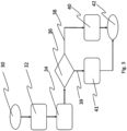
- Fig. 3 shows an example of a flow chart according to a method of the present invention.
- the method starts with reference number 30.
- a step of connecting the charging cable to an electric vehicle takes place.
- the locking apparatus is controlled. It is checked in step 36 if the sensor is activated. In case the sensor is activated (reference number 38) charging starts (reference number 40). In case the sensor is not activated (reference number 39) an error message is sent (e.g. "do not start charging") (cf. reference number 41). After step 40 or step 41 the method ends (cf. reference number 42).
Landscapes
- Engineering & Computer Science (AREA)
- Power Engineering (AREA)
- Transportation (AREA)
- Mechanical Engineering (AREA)
- Details Of Connecting Devices For Male And Female Coupling (AREA)
- Charge And Discharge Circuits For Batteries Or The Like (AREA)
- Electric Propulsion And Braking For Vehicles (AREA)
Description
- The present invention refers according to
claim 1 to a power plug of a charging cable for charging an electric device, according toclaim 6 to a cable having at least one of said power plugs, according to claim 8 to a power socket, according to claim 12 to a charging station comprising at least one of said power sockets and according to claim 13 to a method for charging an electric device, in particularly an electric vehicle. - Document
US9211799B2 - Document
DE102011001436B3 discloses a safety device, which has a locking device that is provided to selectively lock or release an electrical plug connector device. A lock detector determines current state of the locking device and provides an electrical signal indicating information about the current locking state. The information containing existence and nature of fault condition is included in the electrical signal, if a disturbance is detected by the lock detector. - Document
US2014167695A1 discloses a lock device which locks a locking subject to a power port. The lock device is provided with a lock mechanism including a lock member that is movable between a lock position and an unlock position. The lock mechanism moves the lock member to the lock position to lock the locking subject and moves the lock member to the unlock position to unlock the locking subject. A location registration unit registers, as a registered location, a location where switching of the locking subject between a lock state and an unlock state is prohibited or permitted. A location acquisition unit acquires a present location of the lock device. A switching control unit compares the present location with the registered location and controls the lock mechanism based on the comparison to switch the locking subject between the lock state and the unlock state. - Document
US2014169865A1 discloses a lock device. The lock device locks or unlocks a locking subject includes a lock member moved between a lock position where the lock member locks the locking subject and an unlock position where the lock member unlocks the unlocking subject and a movable transmission member that acts to move the lock member to at least the lock position. A guide mechanism is arranged between the transmission member and the lock member. The guide mechanism includes a sloped lock guide surface. The lock guide surface guides the lock member to the lock position when the transmission member moves in a first direction. - According to the standards of electric vehicles, the charging cable must be locked by the socket outlet of a charging station. With this interlock, it is guaranteed that no arcing occurs at the socket outlet of the charging station while electric vehicle is charging. In addition, this interlock prevents charging cable from being stolen. In the market, latching device of interlocks are made of a plastic material. For this reason, the plastic locking apparatus can be broken under extreme forces. An electric vehicle charging station with a broken latching device cannot lock the charging cable properly. Therefore, an arc can be seen at the socket outlet of charging stations or charging cables of users can be stolen. In such a case, charging stations cannot meet charging station standards. Interlocks in the charging station lock charging cables with a motor. These interlocks give the position of the motor as feedback.
- Thus, it is the object of the present invention to enhance safety while charging an electric vehicle.
- The before mentioned object is solved by a power plug according to
claim 1. - The power plug of the present invention is a power plug of a charging cable for charging an electric device, in particular an electric vehicle. The power plug at least comprises multiple contacts for conducting electric energy and/or signals, wherein each contact is linked with an individual wire, a housing for at least partially covering the contacts and/or the wires, wherein the housing comprises a coupling means for locking the contacts in a predefined position in a power socket, wherein the coupling means comprises a sensor element for detecting the predefined position. The housing comprises an inner surface which at least partially surrounds the contacts and/or wires and an outer surface which forms the coupling means, wherein the coupling means is shaped as a latching hole and wherein the sensor element is arranged inside the latching hole. The sensor element is a touch sensor for detecting contact between the power plug and the power socket in case the power plug is positioned into the power socket in the predefined position.
- This solution is beneficial since feedback can be provided due to the sensor element whether the coupling means is working fine or has been broken.
- Further preferred embodiments are subject-matter of the following specification parts and/or of the dependent claims.
- According to a preferred embodiment of the present invention the sensor element outputs signals and/or data, wherein the signals and/or data are transmittable to a control unit of a charging station for activating power supply into the power plug. This embodiment is beneficial since it is possible to detect a damaged coupling means, in case no or wrong signals and/or data are outputted by the sensor element.
- The signals and/or data are transmitted via a wireless signal and/or data transfer means, in particular via WiFi or Bluetooth or NFC, or the signals and/or data are transmitted via at least one wire arranged inside the housing. It is possible that the wire connects both ends of a cable. It is alternatively possible that the cable only extends between the sensor element and the nearest or closest end of the cable to which the power plug belongs.
- The touch sensor is according to a further preferred embodiment of the present invention additionally configured to detect light changes, pressure changes, tilt changes, changes in a magnetic field and/or current changes.
- According to a further preferred embodiment of the present invention, it is also possible that the outer surface of the housing comprises a trench or guiding section via which the coupling means is guided into a predefined coupling position. The trench or guiding section preferably has at least partially a spiral shape.
- The before mentioned object is also solved by a cable comprising a plug according to any of the preceding claims. The cable preferably comprises two or exactly two power plugs according to the present invention.
- The before mentioned object is also solved by a power socket, in particular for coupling with a power plug according to
claim 1. The power socket preferably comprises multiple socket contacts for conducting electric energy and/or signals, wherein each socket contact is linked with an individual socket wire, a socket housing for at least partially covering the socket contacts and/or the socket wires, wherein the socket housing comprises a socket coupling means for locking contacts of the power plug in the predefined position, wherein the socket coupling means comprises a socket sensor element for detecting the predefined position. The socket housing comprises an inner surface which at least partially surrounds the socket contacts and which forms the socket coupling means, wherein the socket coupling means is shaped as a protruding element, in particular a rod or trunnion or pin or projection, and wherein the socket sensor element is arranged on the protruding element. The socket sensor element is a touch sensor for detecting contact between the power plug and the power socket in case the power plug is positioned into the power socket in the predefined position. This embodiment is beneficial since the coupling means can be provided as part of the power socket and not necessarily as part of the power plug. This embodiment is also beneficial since the socket sensor element is positioned in such a manner that the sensor element is only triggered in case a counter element of the power plug contacts the socket sensor element. - The socket sensor element outputs according to a further preferred embodiment of the present invention signals and/or data, wherein the signals and/or data are transmittable to a control unit, in particular of a charging station, for activating power supply into the power plug. This embodiment is beneficial since the control unit only starts charging after at least the sensor signals and/or sensor data are received and/or analyzed.
- The signals and/or data are transmitted via a wireless signal and/or data transfer means of the socket, in particular via WiFi or Bluetooth or NFC, or the signals and/or data are transmitted via a wire arranged inside the socket housing. This embodiment is beneficial since the socket can be wirelessly connected to the control unit.
- The touch sensor is according to a further preferred embodiment of the present invention additionally configured to detect light changes, pressure changes, tilt changes, changes in a magnetic field and/or current changes.
- According to a further preferred embodiment of the present invention, it is also possible that the protruding element, in particular latch or pin, can be moved, in particular in a radial direction. Movements of the protruding element are preferably carried out by means of an actuator, in particular an electric motor. This embodiment is beneficial since the cable can be manufactured without a sensor element, since the power socket comprises the sensor element. The sensor element is preferably a touch sensor, in particularly a conductive element or a pressure measuring element.
- The before mentioned object is further solved by a charging station. Said charging station comprises at least one power socket and preferably at least multiple power sockets according to any of claims 5 to 7.
- The before-mentioned object is further solved by a method for charging an electric device, in particular an electric vehicle. The method according to the present invention preferably comprises at least the steps: Providing a power socket having a socket coupling means for arranging a power plug of a cable in a predefined position, wherein the cable connects the power plug with an electric device, in particular an electric vehicle, providing the power plug as hereinbefore described, wherein the socket coupling means and/or the coupling means of the power plug each comprises a respective sensor element, inserting the power plug into the power socket, outputting signals and/or data in case the power plug and the power socket are arranged with respect to each other in a predefined position, and starting charging. The control unit preferably detects and/or analyzes the signals and/or data. The predefined position is a position in which the power plug is arranged in such a manner on or inside the power socket that electric energy can be transmitted. The charging station controls or evaluates interlock feedback before charging starts or a charging state is registered. The station preferably starts charging in case high logic level feedback is present. The sensor element outputs low logic level in case the socket coupling means is broken or is unlocked. High logic level occurs or is present in case the locking is successfully carried out.
- For a more complete understanding of the present invention and advantages thereof, reference is now made to the following description taken in conjunction with the accompanying drawings. The invention is explained in more detail below using an exemplary embodiment which is specified in the schematic figures of the drawings, in which:
- Fig. 1
- shows an example of a first arrangement according to the present invention, wherein a sensor element is part of a latch or attached thereto,
- Fig. 2
- shows an example of a second arrangement according to the present invention, wherein a sensor element is part of a latch hole or attached thereto, and
- Fig. 3
- shows an example of a flow chart about a preferred sequence according to the present invention.
-
Fig. 1 of the present invention shows apower plug 1 which is connected to a cable 5 or which provides a cable 5. The cable 5 preferably comprises multiple wires, in particular electrically shielded wires. Reference number 2 refers to a housing ofpower plug 1 and reference number 3 refers to a grip which is preferably formed by sections of the housing. A surface section ofpower plug 1 forms or comprises a coupling means 4. The coupling means 4 is preferably used to set-up a form closure withpower socket 6, or with a socket coupling means 16. Thepower socket 6 preferably comprises at least multiple socket contacts for conducting electric energy and/or signals, wherein each socket contact is linked with an individual socket wire, asocket housing 14 for at least partially covering the socket contacts and/or the socket wires. Thus, thesocket housing 14 preferably comprises the socket coupling means 16, in particular socket latching means, for locking, in particular latching, contacts of thepower plug 1 in a predefined position, wherein the socket coupling means 16 comprises asocket sensor element 18, in particular a touch sensor, for detecting the predefined position.Reference number 24 refers to an actuating means for moving the socket coupling means 16 from an unlocked position into a locked position and vice versa. - The
socket housing 14 preferably comprises an inner surface which at least partially surrounds the socket contacts and which forms the socket coupling means 16. The socket coupling means 16 is preferably shaped as a protruding element, in particular rod or trunnion or pin or projection. Thesocket sensor element 18 is preferably arranged on the protruding element. -
Reference number 20 preferably identifies a joint which couples alid 22 to a housing of thepower socket 6. -
Fig. 2 shows an embodiment, which is similar to the one shown inFig 1 . However, thesensor element 8 is arranged inside the coupling means 4 or as part of coupling means 4. - The present invention therefore also refers to a
power plug 1 of a charging cable for charging an electric device, in particular an electric vehicle. Thepower plug 1 preferably comprises at least multiple contacts for conducting electric energy and/or signals, wherein each contact is linked with an individual wire, a housing 2 for at least partially covering the contacts and/or the wires, wherein the housing 2 comprises a coupling means 4, in particular latching means, for locking, in particular latching, the contacts in a predefined position in apower socket 6, wherein the coupling means 4 comprises asensor element 8 for detecting the predefined position. - The housing 2 preferably comprises an inner surface which at least partially surrounds the contacts and/or wires and an
outer surface 10 which forms the coupling means. The coupling means 4 is preferably shaped as a latching hole. Thesensor element 8 is preferably arranged inside the latching hole. -
Fig. 3 shows an example of a flow chart according to a method of the present invention. - The method starts with
reference number 30. According to reference number 32 a step of connecting the charging cable to an electric vehicle takes place. Instep 34 the locking apparatus is controlled. It is checked instep 36 if the sensor is activated. In case the sensor is activated (reference number 38) charging starts (reference number 40). In case the sensor is not activated (reference number 39) an error message is sent (e.g. "do not start charging") (cf. reference number 41). Afterstep 40 or step 41 the method ends (cf. reference number 42). -
- 1
- power plug
- 2
- housing
- 3
- grip
- 4
- coupling means
- 5
- cable
- 6
- power socket
- 8
- sensor element
- 10
- outer surface
- 14
- socket housing
- 16
- socket coupling means
- 18
- socket sensor element
- 20
- joint
- 22
- lid
- 24
- actuator
- 30
- start
- 32
- connecting the charging cable to electric vehicle
- 34
- control the locking apparatus
- 36
- is sensor activated
- 38
- yes
- 39
- no
- 40
- start the charging
- 41
- send error message - do not start charging
- 42
- end
Claims (9)
- Power plug (1) of a charging cable for charging an electric device, in particular an electric vehicle, the power plug at least comprising:multiple contacts for conducting electrical energy and/or signals, wherein each contact is linked with an individual wire,a housing (2) for at least partially covering the contacts and/or the wires,wherein the housing (2) comprises a coupling means (4) for locking the contacts in a predefined position in a power socket (6),wherein the coupling means (4) comprises a sensor element (8) for detecting the predefined position,characterized in that:the housing (2) comprises an inner surface which at least partially surrounds the contacts and/or wires and an outer surface (10) which forms the coupling means, wherein the coupling means (4) is shaped as a latching hole and wherein the sensor element (8) is arranged inside the latching hole; andthe sensor element (8) is a touch sensor for detecting contact between the power plug (1) and the power socket (6) in case the power plug is positioned into the power socket in the predefined position.
- Plug according to claim 1, characterized in that:the sensor element (8) outputs signals and/or data, wherein the signals and/or data are transmittable to a control unit of a charging station for activating power supply into the power plug;wherein the signals and/or data are transmitted via a wireless signal and/or data transfer means, in particular via WiFi or Bluetooth or NFC,
orthe signals and/or data are transmitted via a wire arranged inside the housing (2). - Plug according to any of the preceding claims, characterized in that:
the touch sensor is additionally configured to detect light changes, pressure changes, tilt changes, changes in a magnetic field and/or current changes. - Cable (12) comprising a plug according to any of the preceding claims.
- Power socket (6) for coupling with the power plug according to claim 1, the power socket at least comprising:multiple socket contacts for conducting electric energy and/or signals, wherein each socket contact is linked with an individual socket wire,a socket housing (14) for at least partially covering the socket contacts and/or the socket wires,wherein the socket housing (14) comprises a socket coupling means (16) for locking contacts of the power plug (1) in the predefined position,wherein the socket coupling means (16) comprises a socket sensor element (18) for detecting the predefined position,characterized in that:the socket housing (14) comprises an inner surface which at least partially surrounds the socket contacts and which forms the socket coupling means (16), wherein the socket coupling means (16) is shaped as a protruding element, in particular a rod or trunnion or pin or projection, and wherein the socket sensor element (18) is arranged on the protruding element; andthe socket sensor element (18) is a touch sensor for detecting contact between the power plug and the power socket in case the power plug is positioned into the power socket in the predefined position.
- Socket according to claim 5, characterized in that:the socket sensor element (18) outputs signals and/or data, wherein the signals and/or data are transmittable to a control unit of a charging station for activating power supply into the power plug;wherein the signals and/or data are transmitted via a wireless signal and/or data transfer means of the socket, in particular via WiFi or Bluetooth or NFC,
orthe signals and/or data are transmitted via a wire arranged inside the socket housing (14). - Socket according to claim 5 or claim 6, characterized in that:
the touch sensor is additionally configured to detect light changes, pressure changes, tilt changes, changes in a magnetic field and/or current changes. - Charging station comprising at least one power socket according to any of claims 5 to 7.
- Method for charging an electric device, in particular an electric vehicle, the method at least comprising:providing a power socket (6) having a socket coupling means (4) for arranging a power plug (1) of a cable (6) in a predefined position, wherein the cable (6) connects the power plug with an electric device, in particular an electric vehicle,providing the power plug (1) according to claim 1,wherein the socket coupling means (16) and/or the coupling means (4) of the power plug each comprises a respective sensor element (8, 18),inserting the power plug (1) into the power socket (6),outputting signals and/or data in case the power plug (1) and the power socket (6) are arranged with respect to each other in a predefined position, andstarting charging.
Priority Applications (1)
| Application Number | Priority Date | Filing Date | Title |
|---|---|---|---|
| EP18192893.8A EP3620325B1 (en) | 2018-09-06 | 2018-09-06 | Power plug or power socket with coupling means detecting sensor |
Applications Claiming Priority (1)
| Application Number | Priority Date | Filing Date | Title |
|---|---|---|---|
| EP18192893.8A EP3620325B1 (en) | 2018-09-06 | 2018-09-06 | Power plug or power socket with coupling means detecting sensor |
Publications (2)
| Publication Number | Publication Date |
|---|---|
| EP3620325A1 EP3620325A1 (en) | 2020-03-11 |
| EP3620325B1 true EP3620325B1 (en) | 2023-08-16 |
Family
ID=63524122
Family Applications (1)
| Application Number | Title | Priority Date | Filing Date |
|---|---|---|---|
| EP18192893.8A Active EP3620325B1 (en) | 2018-09-06 | 2018-09-06 | Power plug or power socket with coupling means detecting sensor |
Country Status (1)
| Country | Link |
|---|---|
| EP (1) | EP3620325B1 (en) |
Families Citing this family (4)
| Publication number | Priority date | Publication date | Assignee | Title |
|---|---|---|---|---|
| CN111355069B (en) * | 2020-03-17 | 2021-11-16 | 徐家贵 | New energy automobile mouth automatically regulated fixing device that charges |
| CN111502421B (en) * | 2020-04-08 | 2021-06-04 | 重庆长安汽车股份有限公司 | Locking method of electronic lock of charging gun |
| CN113415182B (en) * | 2021-06-03 | 2023-01-06 | 海纳同和智慧物联网(秦皇岛)有限责任公司 | High-power intelligent charging system with electronic lock |
| EP4640479A1 (en) * | 2024-04-23 | 2025-10-29 | Volvo Truck Corporation | An electric vehicle charging socket with an electrically conducting latch |
Citations (2)
| Publication number | Priority date | Publication date | Assignee | Title |
|---|---|---|---|---|
| US20130078840A1 (en) * | 2011-09-28 | 2013-03-28 | Kabushiki Kaisha Tokai Rika Denki Seisakusho | Power plug locking device |
| JP2014120230A (en) * | 2012-12-13 | 2014-06-30 | Tokai Rika Co Ltd | Lock device |
Family Cites Families (5)
| Publication number | Priority date | Publication date | Assignee | Title |
|---|---|---|---|---|
| DE102011001436B3 (en) | 2011-03-21 | 2012-07-19 | Küster Holding GmbH | Safety device for electrical plug connector device used in e.g. electric vehicle, provides electrical signal including information containing existence and nature of fault condition, if disturbance is detected by lock detector |
| US20130337669A1 (en) * | 2012-06-13 | 2013-12-19 | Schneider Electric USA, Inc. | Locking device for electric vehicle charging connector |
| JP5922565B2 (en) * | 2012-12-13 | 2016-05-24 | 株式会社東海理化電機製作所 | Locking device |
| JP2014117974A (en) * | 2012-12-13 | 2014-06-30 | Tokai Rika Co Ltd | Lock device |
| US9211799B2 (en) | 2013-08-15 | 2015-12-15 | Telefonix, Inc. | Mechanism for locking and fault detection in the electrical vehicle supply equipment cord |
-
2018
- 2018-09-06 EP EP18192893.8A patent/EP3620325B1/en active Active
Patent Citations (2)
| Publication number | Priority date | Publication date | Assignee | Title |
|---|---|---|---|---|
| US20130078840A1 (en) * | 2011-09-28 | 2013-03-28 | Kabushiki Kaisha Tokai Rika Denki Seisakusho | Power plug locking device |
| JP2014120230A (en) * | 2012-12-13 | 2014-06-30 | Tokai Rika Co Ltd | Lock device |
Also Published As
| Publication number | Publication date |
|---|---|
| EP3620325A1 (en) | 2020-03-11 |
Similar Documents
| Publication | Publication Date | Title |
|---|---|---|
| EP3620325B1 (en) | Power plug or power socket with coupling means detecting sensor | |
| EP2308140B1 (en) | Electrical connector system, an electrical device comprising the same and a method for unmating the same | |
| US11292354B2 (en) | Method and system for communication between a vehicle and a charging station for unlocking mechanical charging cable coupling | |
| EP2863488B1 (en) | Connector | |
| CN113400967B (en) | Vehicle with a vehicle body having a vehicle body support | |
| JP5958432B2 (en) | vehicle | |
| US10707623B2 (en) | Charging system for vehicle | |
| JP6289851B2 (en) | Plug-in connector and plug-in connection member | |
| CN105703165B (en) | Connection systems for power circuits and equipment for charging electric vehicles therewith | |
| US10910777B2 (en) | Charging connection for a motor vehicle | |
| US20180166818A1 (en) | High-voltage connector and high-voltage power supply connecting device having the same | |
| WO2014145629A1 (en) | Connector system with connection sensor | |
| CN106486841A (en) | There is the plug-in connector part of locking member | |
| KR20210018730A (en) | Charging connector locking apparatus for electric vehicle and control method thereof | |
| US9647389B2 (en) | Plug connector part comprising a locking element | |
| CN112659934A (en) | System for automatically unlocking a charging plug | |
| KR20210149853A (en) | Device for connecting fluid lines and other lines | |
| JP2014167875A (en) | Connector device | |
| CN114374122B (en) | Plug device and method for explosion-proof cable connector | |
| JP2016015341A (en) | Electric connector, electric connector unit, and charger for electric vehicle | |
| JP2008235253A (en) | Connector assembly with slider | |
| JP2019175559A (en) | Charging extension cable for electric vehicles | |
| CN121263326A (en) | Locking device for locking two charging interfaces, system having such a locking device, and method for controlling such a locking device |
Legal Events
| Date | Code | Title | Description |
|---|---|---|---|
| PUAI | Public reference made under article 153(3) epc to a published international application that has entered the european phase |
Free format text: ORIGINAL CODE: 0009012 |
|
| STAA | Information on the status of an ep patent application or granted ep patent |
Free format text: STATUS: THE APPLICATION HAS BEEN PUBLISHED |
|
| AK | Designated contracting states |
Kind code of ref document: A1 Designated state(s): AL AT BE BG CH CY CZ DE DK EE ES FI FR GB GR HR HU IE IS IT LI LT LU LV MC MK MT NL NO PL PT RO RS SE SI SK SM TR |
|
| AX | Request for extension of the european patent |
Extension state: BA ME |
|
| STAA | Information on the status of an ep patent application or granted ep patent |
Free format text: STATUS: REQUEST FOR EXAMINATION WAS MADE |
|
| 17P | Request for examination filed |
Effective date: 20200909 |
|
| RBV | Designated contracting states (corrected) |
Designated state(s): AL AT BE BG CH CY CZ DE DK EE ES FI FR GB GR HR HU IE IS IT LI LT LU LV MC MK MT NL NO PL PT RO RS SE SI SK SM TR |
|
| STAA | Information on the status of an ep patent application or granted ep patent |
Free format text: STATUS: EXAMINATION IS IN PROGRESS |
|
| 17Q | First examination report despatched |
Effective date: 20210916 |
|
| GRAP | Despatch of communication of intention to grant a patent |
Free format text: ORIGINAL CODE: EPIDOSNIGR1 |
|
| STAA | Information on the status of an ep patent application or granted ep patent |
Free format text: STATUS: GRANT OF PATENT IS INTENDED |
|
| INTG | Intention to grant announced |
Effective date: 20230315 |
|
| GRAS | Grant fee paid |
Free format text: ORIGINAL CODE: EPIDOSNIGR3 |
|
| GRAA | (expected) grant |
Free format text: ORIGINAL CODE: 0009210 |
|
| STAA | Information on the status of an ep patent application or granted ep patent |
Free format text: STATUS: THE PATENT HAS BEEN GRANTED |
|
| AK | Designated contracting states |
Kind code of ref document: B1 Designated state(s): AL AT BE BG CH CY CZ DE DK EE ES FI FR GB GR HR HU IE IS IT LI LT LU LV MC MK MT NL NO PL PT RO RS SE SI SK SM TR |
|
| REG | Reference to a national code |
Ref country code: CH Ref legal event code: EP |
|
| REG | Reference to a national code |
Ref country code: DE Ref legal event code: R096 Ref document number: 602018055361 Country of ref document: DE |
|
| REG | Reference to a national code |
Ref country code: IE Ref legal event code: FG4D |
|
| REG | Reference to a national code |
Ref country code: LT Ref legal event code: MG9D |
|
| REG | Reference to a national code |
Ref country code: NL Ref legal event code: MP Effective date: 20230816 |
|
| REG | Reference to a national code |
Ref country code: AT Ref legal event code: MK05 Ref document number: 1599725 Country of ref document: AT Kind code of ref document: T Effective date: 20230816 |
|
| PG25 | Lapsed in a contracting state [announced via postgrant information from national office to epo] |
Ref country code: GR Free format text: LAPSE BECAUSE OF FAILURE TO SUBMIT A TRANSLATION OF THE DESCRIPTION OR TO PAY THE FEE WITHIN THE PRESCRIBED TIME-LIMIT Effective date: 20231117 |
|
| PG25 | Lapsed in a contracting state [announced via postgrant information from national office to epo] |
Ref country code: IS Free format text: LAPSE BECAUSE OF FAILURE TO SUBMIT A TRANSLATION OF THE DESCRIPTION OR TO PAY THE FEE WITHIN THE PRESCRIBED TIME-LIMIT Effective date: 20231216 |
|
| PG25 | Lapsed in a contracting state [announced via postgrant information from national office to epo] |
Ref country code: SE Free format text: LAPSE BECAUSE OF FAILURE TO SUBMIT A TRANSLATION OF THE DESCRIPTION OR TO PAY THE FEE WITHIN THE PRESCRIBED TIME-LIMIT Effective date: 20230816 Ref country code: RS Free format text: LAPSE BECAUSE OF FAILURE TO SUBMIT A TRANSLATION OF THE DESCRIPTION OR TO PAY THE FEE WITHIN THE PRESCRIBED TIME-LIMIT Effective date: 20230816 Ref country code: PT Free format text: LAPSE BECAUSE OF FAILURE TO SUBMIT A TRANSLATION OF THE DESCRIPTION OR TO PAY THE FEE WITHIN THE PRESCRIBED TIME-LIMIT Effective date: 20231218 Ref country code: NO Free format text: LAPSE BECAUSE OF FAILURE TO SUBMIT A TRANSLATION OF THE DESCRIPTION OR TO PAY THE FEE WITHIN THE PRESCRIBED TIME-LIMIT Effective date: 20231116 Ref country code: NL Free format text: LAPSE BECAUSE OF FAILURE TO SUBMIT A TRANSLATION OF THE DESCRIPTION OR TO PAY THE FEE WITHIN THE PRESCRIBED TIME-LIMIT Effective date: 20230816 Ref country code: LV Free format text: LAPSE BECAUSE OF FAILURE TO SUBMIT A TRANSLATION OF THE DESCRIPTION OR TO PAY THE FEE WITHIN THE PRESCRIBED TIME-LIMIT Effective date: 20230816 Ref country code: LT Free format text: LAPSE BECAUSE OF FAILURE TO SUBMIT A TRANSLATION OF THE DESCRIPTION OR TO PAY THE FEE WITHIN THE PRESCRIBED TIME-LIMIT Effective date: 20230816 Ref country code: IS Free format text: LAPSE BECAUSE OF FAILURE TO SUBMIT A TRANSLATION OF THE DESCRIPTION OR TO PAY THE FEE WITHIN THE PRESCRIBED TIME-LIMIT Effective date: 20231216 Ref country code: HR Free format text: LAPSE BECAUSE OF FAILURE TO SUBMIT A TRANSLATION OF THE DESCRIPTION OR TO PAY THE FEE WITHIN THE PRESCRIBED TIME-LIMIT Effective date: 20230816 Ref country code: GR Free format text: LAPSE BECAUSE OF FAILURE TO SUBMIT A TRANSLATION OF THE DESCRIPTION OR TO PAY THE FEE WITHIN THE PRESCRIBED TIME-LIMIT Effective date: 20231117 Ref country code: FI Free format text: LAPSE BECAUSE OF FAILURE TO SUBMIT A TRANSLATION OF THE DESCRIPTION OR TO PAY THE FEE WITHIN THE PRESCRIBED TIME-LIMIT Effective date: 20230816 Ref country code: AT Free format text: LAPSE BECAUSE OF FAILURE TO SUBMIT A TRANSLATION OF THE DESCRIPTION OR TO PAY THE FEE WITHIN THE PRESCRIBED TIME-LIMIT Effective date: 20230816 |
|
| PG25 | Lapsed in a contracting state [announced via postgrant information from national office to epo] |
Ref country code: PL Free format text: LAPSE BECAUSE OF FAILURE TO SUBMIT A TRANSLATION OF THE DESCRIPTION OR TO PAY THE FEE WITHIN THE PRESCRIBED TIME-LIMIT Effective date: 20230816 |
|
| REG | Reference to a national code |
Ref country code: DE Ref legal event code: R119 Ref document number: 602018055361 Country of ref document: DE |
|
| PG25 | Lapsed in a contracting state [announced via postgrant information from national office to epo] |
Ref country code: ES Free format text: LAPSE BECAUSE OF FAILURE TO SUBMIT A TRANSLATION OF THE DESCRIPTION OR TO PAY THE FEE WITHIN THE PRESCRIBED TIME-LIMIT Effective date: 20230816 |
|
| PG25 | Lapsed in a contracting state [announced via postgrant information from national office to epo] |
Ref country code: SM Free format text: LAPSE BECAUSE OF FAILURE TO SUBMIT A TRANSLATION OF THE DESCRIPTION OR TO PAY THE FEE WITHIN THE PRESCRIBED TIME-LIMIT Effective date: 20230816 Ref country code: RO Free format text: LAPSE BECAUSE OF FAILURE TO SUBMIT A TRANSLATION OF THE DESCRIPTION OR TO PAY THE FEE WITHIN THE PRESCRIBED TIME-LIMIT Effective date: 20230816 Ref country code: ES Free format text: LAPSE BECAUSE OF FAILURE TO SUBMIT A TRANSLATION OF THE DESCRIPTION OR TO PAY THE FEE WITHIN THE PRESCRIBED TIME-LIMIT Effective date: 20230816 Ref country code: EE Free format text: LAPSE BECAUSE OF FAILURE TO SUBMIT A TRANSLATION OF THE DESCRIPTION OR TO PAY THE FEE WITHIN THE PRESCRIBED TIME-LIMIT Effective date: 20230816 Ref country code: DK Free format text: LAPSE BECAUSE OF FAILURE TO SUBMIT A TRANSLATION OF THE DESCRIPTION OR TO PAY THE FEE WITHIN THE PRESCRIBED TIME-LIMIT Effective date: 20230816 Ref country code: CZ Free format text: LAPSE BECAUSE OF FAILURE TO SUBMIT A TRANSLATION OF THE DESCRIPTION OR TO PAY THE FEE WITHIN THE PRESCRIBED TIME-LIMIT Effective date: 20230816 Ref country code: SK Free format text: LAPSE BECAUSE OF FAILURE TO SUBMIT A TRANSLATION OF THE DESCRIPTION OR TO PAY THE FEE WITHIN THE PRESCRIBED TIME-LIMIT Effective date: 20230816 |
|
| REG | Reference to a national code |
Ref country code: CH Ref legal event code: PL |
|
| PG25 | Lapsed in a contracting state [announced via postgrant information from national office to epo] |
Ref country code: LU Free format text: LAPSE BECAUSE OF NON-PAYMENT OF DUE FEES Effective date: 20230906 |
|
| REG | Reference to a national code |
Ref country code: BE Ref legal event code: MM Effective date: 20230930 |
|
| PG25 | Lapsed in a contracting state [announced via postgrant information from national office to epo] |
Ref country code: LU Free format text: LAPSE BECAUSE OF NON-PAYMENT OF DUE FEES Effective date: 20230906 Ref country code: MC Free format text: LAPSE BECAUSE OF FAILURE TO SUBMIT A TRANSLATION OF THE DESCRIPTION OR TO PAY THE FEE WITHIN THE PRESCRIBED TIME-LIMIT Effective date: 20230816 |
|
| PLBE | No opposition filed within time limit |
Free format text: ORIGINAL CODE: 0009261 |
|
| STAA | Information on the status of an ep patent application or granted ep patent |
Free format text: STATUS: NO OPPOSITION FILED WITHIN TIME LIMIT |
|
| REG | Reference to a national code |
Ref country code: IE Ref legal event code: MM4A |
|
| PG25 | Lapsed in a contracting state [announced via postgrant information from national office to epo] |
Ref country code: IE Free format text: LAPSE BECAUSE OF NON-PAYMENT OF DUE FEES Effective date: 20230906 |
|
| PG25 | Lapsed in a contracting state [announced via postgrant information from national office to epo] |
Ref country code: CH Free format text: LAPSE BECAUSE OF NON-PAYMENT OF DUE FEES Effective date: 20230930 |
|
| 26N | No opposition filed |
Effective date: 20240517 |
|
| GBPC | Gb: european patent ceased through non-payment of renewal fee |
Effective date: 20231116 |
|
| PG25 | Lapsed in a contracting state [announced via postgrant information from national office to epo] |
Ref country code: IT Free format text: LAPSE BECAUSE OF FAILURE TO SUBMIT A TRANSLATION OF THE DESCRIPTION OR TO PAY THE FEE WITHIN THE PRESCRIBED TIME-LIMIT Effective date: 20230816 Ref country code: IE Free format text: LAPSE BECAUSE OF NON-PAYMENT OF DUE FEES Effective date: 20230906 Ref country code: FR Free format text: LAPSE BECAUSE OF NON-PAYMENT OF DUE FEES Effective date: 20231016 Ref country code: DE Free format text: LAPSE BECAUSE OF NON-PAYMENT OF DUE FEES Effective date: 20240403 Ref country code: CH Free format text: LAPSE BECAUSE OF NON-PAYMENT OF DUE FEES Effective date: 20230930 Ref country code: SI Free format text: LAPSE BECAUSE OF FAILURE TO SUBMIT A TRANSLATION OF THE DESCRIPTION OR TO PAY THE FEE WITHIN THE PRESCRIBED TIME-LIMIT Effective date: 20230816 |
|
| PG25 | Lapsed in a contracting state [announced via postgrant information from national office to epo] |
Ref country code: BE Free format text: LAPSE BECAUSE OF NON-PAYMENT OF DUE FEES Effective date: 20230930 |
|
| PG25 | Lapsed in a contracting state [announced via postgrant information from national office to epo] |
Ref country code: GB Free format text: LAPSE BECAUSE OF NON-PAYMENT OF DUE FEES Effective date: 20231116 |
|
| PG25 | Lapsed in a contracting state [announced via postgrant information from national office to epo] |
Ref country code: GB Free format text: LAPSE BECAUSE OF NON-PAYMENT OF DUE FEES Effective date: 20231116 |
|
| PG25 | Lapsed in a contracting state [announced via postgrant information from national office to epo] |
Ref country code: BG Free format text: LAPSE BECAUSE OF FAILURE TO SUBMIT A TRANSLATION OF THE DESCRIPTION OR TO PAY THE FEE WITHIN THE PRESCRIBED TIME-LIMIT Effective date: 20230816 |
|
| PG25 | Lapsed in a contracting state [announced via postgrant information from national office to epo] |
Ref country code: BG Free format text: LAPSE BECAUSE OF FAILURE TO SUBMIT A TRANSLATION OF THE DESCRIPTION OR TO PAY THE FEE WITHIN THE PRESCRIBED TIME-LIMIT Effective date: 20230816 |
|
| PG25 | Lapsed in a contracting state [announced via postgrant information from national office to epo] |
Ref country code: CY Free format text: LAPSE BECAUSE OF FAILURE TO SUBMIT A TRANSLATION OF THE DESCRIPTION OR TO PAY THE FEE WITHIN THE PRESCRIBED TIME-LIMIT; INVALID AB INITIO Effective date: 20180906 |
|
| PG25 | Lapsed in a contracting state [announced via postgrant information from national office to epo] |
Ref country code: HU Free format text: LAPSE BECAUSE OF FAILURE TO SUBMIT A TRANSLATION OF THE DESCRIPTION OR TO PAY THE FEE WITHIN THE PRESCRIBED TIME-LIMIT; INVALID AB INITIO Effective date: 20180906 |
|
| PG25 | Lapsed in a contracting state [announced via postgrant information from national office to epo] |
Ref country code: TR Free format text: LAPSE BECAUSE OF FAILURE TO SUBMIT A TRANSLATION OF THE DESCRIPTION OR TO PAY THE FEE WITHIN THE PRESCRIBED TIME-LIMIT Effective date: 20230816 |