EP3620317A1 - Air treatment apparatus and valve mechanism - Google Patents
Air treatment apparatus and valve mechanism Download PDFInfo
- Publication number
- EP3620317A1 EP3620317A1 EP19195325.6A EP19195325A EP3620317A1 EP 3620317 A1 EP3620317 A1 EP 3620317A1 EP 19195325 A EP19195325 A EP 19195325A EP 3620317 A1 EP3620317 A1 EP 3620317A1
- Authority
- EP
- European Patent Office
- Prior art keywords
- valve
- inlet
- air
- valve mechanism
- filtration
- Prior art date
- Legal status (The legal status is an assumption and is not a legal conclusion. Google has not performed a legal analysis and makes no representation as to the accuracy of the status listed.)
- Withdrawn
Links
Images


Classifications
-
- B—PERFORMING OPERATIONS; TRANSPORTING
- B60—VEHICLES IN GENERAL
- B60H—ARRANGEMENTS OF HEATING, COOLING, VENTILATING OR OTHER AIR-TREATING DEVICES SPECIALLY ADAPTED FOR PASSENGER OR GOODS SPACES OF VEHICLES
- B60H1/00—Heating, cooling or ventilating devices
- B60H1/00357—Air-conditioning arrangements specially adapted for particular vehicles
- B60H1/00378—Air-conditioning arrangements specially adapted for particular vehicles for tractor or load vehicle cabins
-
- B—PERFORMING OPERATIONS; TRANSPORTING
- B60—VEHICLES IN GENERAL
- B60H—ARRANGEMENTS OF HEATING, COOLING, VENTILATING OR OTHER AIR-TREATING DEVICES SPECIALLY ADAPTED FOR PASSENGER OR GOODS SPACES OF VEHICLES
- B60H3/00—Other air-treating devices
- B60H3/06—Filtering
- B60H3/0608—Filter arrangements in the air stream
- B60H3/0633—Filter arrangements in the air stream with provisions for regenerating or cleaning the filter element
-
- B—PERFORMING OPERATIONS; TRANSPORTING
- B60—VEHICLES IN GENERAL
- B60H—ARRANGEMENTS OF HEATING, COOLING, VENTILATING OR OTHER AIR-TREATING DEVICES SPECIALLY ADAPTED FOR PASSENGER OR GOODS SPACES OF VEHICLES
- B60H3/00—Other air-treating devices
- B60H3/06—Filtering
- B60H3/0608—Filter arrangements in the air stream
- B60H3/0641—Filter arrangements in the air stream near ventilating openings in the vehicle exterior
-
- F—MECHANICAL ENGINEERING; LIGHTING; HEATING; WEAPONS; BLASTING
- F16—ENGINEERING ELEMENTS AND UNITS; GENERAL MEASURES FOR PRODUCING AND MAINTAINING EFFECTIVE FUNCTIONING OF MACHINES OR INSTALLATIONS; THERMAL INSULATION IN GENERAL
- F16K—VALVES; TAPS; COCKS; ACTUATING-FLOATS; DEVICES FOR VENTING OR AERATING
- F16K11/00—Multiple-way valves, e.g. mixing valves; Pipe fittings incorporating such valves
- F16K11/02—Multiple-way valves, e.g. mixing valves; Pipe fittings incorporating such valves with all movable sealing faces moving as one unit
- F16K11/04—Multiple-way valves, e.g. mixing valves; Pipe fittings incorporating such valves with all movable sealing faces moving as one unit comprising only lift valves
- F16K11/048—Multiple-way valves, e.g. mixing valves; Pipe fittings incorporating such valves with all movable sealing faces moving as one unit comprising only lift valves with valve seats positioned between movable valve members
Definitions
- the present invention relates to an air treatment apparatus and a valve mechanism for use in the same, in particular an air treatment apparatus for an operator environment or cab of an agricultural vehicle or a similar vehicle.
- Agricultural vehicles are known to operate in environments in which many different kinds of particulate or contaminant are present. This creates a requirement for filtration of the air for operators of such vehicles when in use.
- the particulates may be of different sizes and of different natures, for example larger particulates such as dust, pollen and the like and smaller contaminants such as fumes, aerosols and vapours.
- a first filter may be used when the predominant contaminant in the working environment of the agricultural vehicle is relatively large (for example dust stirred up when traversing a field) and a second filter is used when the predominant contaminant in the working environment is relatively small (for example when applying a herbicide, pesticide or similar).
- EU Standard EN 15695 provides for four categories of filter for cabin protection, where Category 2 protects only against dust but does not protect against aerosols and vapours, Category 3 protects against dust and aerosol, but not vapours and Category 4 protects against dust, aerosols and vapours.
- Category 3 filters tend to be more expensive than Category 2 filters, with Category 4 being most expensive. Accordingly, it is beneficial to the working life of the higher rated filters if they can be cleaned rather than replaced. It is a further advantage if such filters can be cleaned when in service on the agricultural vehicle rather than being removed while being cleaned (requiring replacement during cleaning or enforced downtime of the agricultural vehicle).
- a valve mechanism for an air treatment apparatus comprising a valve chamber having a fluid outlet and first and second fluid inlets, wherein each fluid inlet has a respective valve seat disposed on the exterior of the valve chamber around the inlet, wherein each fluid inlet has a respective valve body movable into engagement with the respective valve seat to close the inlet, and wherein the first and second valve bodies are rigidly connected by a joining body which extends through the fluid inlets and has a length greater than the separation of the valve seats.
- the valve mechanism joining body may be substantially straight, with the valve seats lying in substantially parallel planes.
- the joining body may be a single piece, or may comprise two or more joining body parts extending substantially parallel to each other between the first and second valve bodies.
- the valve mechanism may further comprise an actuator connected to one of the valve bodies by a linkage, which actuator is operable to move the valve body into engagement with the respective valve seat, wherein the linkage and actuator are located outside of the valve chamber, preferably in an area of a filter device outlet.
- the joining body is curved and each of the valve bodies extends substantially perpendicularly from a respective end of the joining body.
- the joining body may define an arc about an axis of rotation with the valve seats lying in respective planes, which planes intersect on a line substantially coincident with the axis of rotation, and the mechanism may further comprise a mounting body having a first end attached to one of the valve bodies and a second end pivotably attached to the valve chamber at or close to the axis of rotation.
- the mounting body and an actuator operable to move the mounting body are preferably located outside of the valve chamber, in an area of a filter device outlet.
- an air treatment apparatus for an operator environment of an agricultural vehicle in which air to be filtered is drawn into an air filtration system, filtered and directed to an agricultural vehicle HVAC system, which HVAC system comprises an inlet plenum, a blower, other HVAC components and an outlet to the operator environment; wherein the air filtration system comprises; at least one external inlet; a first filtration device having a first relatively coarser level of filtration located between the external inlet and the HVAC inlet plenum; a second filtration device having a second relatively finer level of filtration located between the external inlet or a further external inlet and the HVAC inlet plenum; an air filtration system blower connected to the HVAC inlet plenum; and a valve mechanism according to the first aspect of the invention, the valve mechanism having its first input connected to an output of the first filtration device, its second input connected to an output of the second filtration device, and its output connected to the inlet plenum of the HVAC system such that in use an air flow is directed from
- the air treatment apparatus further comprises a bypass connected at a second end adjacent the second filtration device such that in use when the valve mechanism connects the first filtration device to the HVAC inlet plenum a portion of an air flow through the air treatment apparatus is redirected to purge the second filtration device.
- the under pressure provided by the blowers sucks the valve mechanism, especially the valve bodies, against the fluid inlets and therefore helps to achieve an air tightness between the valve chamber and the filter outlet area.
- the valve chamber needs to be absolutely air tight to prevent drawing of contaminated air into the cabin, the mounting body or linkage is not placed in the valve chamber but in the filter outlet area. Therefore it is not needed to seal the mounting body or linkage because the filter outlet area belongs to the not sealed ambient area.
- FIG. 1 a schematic view of a first embodiment of an air filtration apparatus is shown comprising an air filtration system 2 (to the left of the dashed line 3) connected to an HVAC system 4 (to the right of the dashed line 3) for an operator environment or cabin of an agricultural vehicle.
- An external inlet 6 is shown feeding a first vent or duct 8 and a second vent or duct 10 by which air to be filtered is drawn into the filtration system.
- the first and second vents or ducts 8, 10 may be provided with individual external inlets.
- the external inlet 6 may conveniently be located in a roof housing of the cabin of the agricultural vehicle.
- the first vent or duct 8 is directed to a first filtration device 12 having a first relatively coarser level of filtration.
- the first filtration device 12 is conveniently suitable for extracting dust particles and the like from the externally fed air. By way of example, this may be a Category 2 dust filter.
- the first filtration device 12 is provided with an outlet 14.
- the outlet 14 is connected to a first inlet side of a valve mechanism 22 (described in further detail below with reference to Figures 3 to 7 ).
- the second vent or duct 10 is directed to a second filtration device 16 having a second relatively finer level of filtration.
- the second filtration device 16 is conveniently suitable for extracting dust, aerosols, vapour and the like from the externally fed air. By way of example, this may be a Category 4 filter.
- the second filtration device 16 is provided with an outlet 18.
- An air filtration system blower 20, conveniently a fresh air blower, is associated with the second filtration device 16.
- the air filtration system blower 20 is provided with an inlet connected to the outlet 18 of the second filtration device 16 and an outlet connected to a second inlet side of the valve mechanism 22.
- the valve mechanism 22 is provided with an outlet conduit 24.
- the valve mechanism allows air flow from the second filtration device 16 to the outlet conduit 24 while isolating the first filtration device 12 (as in Fig. 1 ) or, alternatively allows air flow from the first filtration device 12 to the outlet conduit 24 while isolating the second filtration device 16 (as in Fig. 2 ).
- the valve mechanism 22 may be operated by any convenient means, for example automatically following a suitable signal received from a suitable sensor, automatically following actuation of a suitable device for example a sprayer, or by the direct action of a driver actuating suitable means within the cab.
- the outlet conduit 24 is connected to an inlet plenum of the HVAC system and in particular connects the outlet conduit 24 to a blower 26 of the HVAC system ('HVAC system blower').
- the HVAC system typically includes additional components 28 downstream of the blower 26, such as by way of example a evaporator and a heater.
- the HVAC blower 26 is provided with a connecting conduit 30 to direct the air flow through the other components before delivery to the cabin by way of a cabin air supply duct 32.
- a first end of a bypass channel or passage 34 is connected to the connecting conduit 30.
- a second end of the bypass channel or passage 34 is located between the second filtration device 16 and the associated air filtration system blower 20.
- a further air recirculation path is provided by a conduit (not shown) extending between the cabin and the outlet conduit 24.
- valve mechanism 22 The typical operating position of the valve mechanism 22 is that shown in Figure 2 , with the inlet air being drawn through the coarser (and cheaper) filter 12. However, when there is a need to extract aerosols, vapour and the like the system is switched to the configuration shown in Figure 1 .
- the valve mechanism 22 is moved to the position shown and the air filtration system blower 20 is also actuated. Air is drawn into the air filtration system through the second vent or duct 10 (arrow A) and drawn through the second filtration device 16 to remove dust, aerosols, vapour and the like entrained in the air. The air is directed through the valve mechanism 22 to the outlet conduit 24 and then drawn by the HVAC system blower 26 into the HVAC system and onward to the cabin air supply duct 32 (arrow B). In this position, the valve mechanism 22 prevents communication between the first filtration device 12 and the HVAC blower 26. A first volume of underpressure (low pressure) is formed between the second filtration device 16 and the air filtration system blower 20. Since the HVAC blower 26 is stronger than the air filtration system blower 20, a second volume of underpressure is created between the air filtration system blower 20 and the HVAC blower 26.
- a first volume of underpressure low pressure
- valve mechanism 22 is caused to adopt the position shown in Figure 2 (the air filtration system blower 20 is also deactivated). In this position, the valve mechanism 22 prevents air flowing from the second filtration device 16 past the air filtration system blower 20 to the inlet plenum of the HVAC blower 26.
- Air is drawn into the air filtration system through the first vent or duct 8 (arrow A) and directed through the first filtration device 12 to remove dust and the like entrained in the air.
- the air passes through the valve mechanism 22 to the outlet conduit 24 and most is then drawn by the HVAC system blower 26 into the HVAC system and out through the cabin air supply duct 32 (arrow B).
- the air filtration system blower 20 is downstream of the valve mechanism 22, coupled to the inlet plenum of the HVAC blower 26.
- an outlet of the air filtration system blower 20 directs air through the bypass channel or passage 34 (arrow C) to the region between the second filtration unit 16 and inlet to the air filtration system blower 20.
- FIG. 3 represents a first embodiment of the valve mechanism 22.
- the mechanism comprises a valve chamber 40 having a fluid outlet 42 coupled with the outlet conduit 24, and first 44 and second 46 fluid inlets respectively coupled with the filter device outlets 18, 14.
- Each of the fluid inlets 44, 46 has a respective valve seat 48, 50 disposed on the exterior of the valve chamber around the inlet.
- Each of the fluid inlets 44, 46 also has a respective valve body 52, 54 movable into engagement with the respective valve seat 48, 50 to close the inlet.
- the first and second valve bodies 52, 54 are rigidly connected by a substantially straight joining body which extends through the fluid inlets 42, 44.
- the joining body 56 has a length greater than the separation of the valve seats 48, 50 so that closing of one of the inlets 44 results in the opening of the other 46.
- An actuator moves the valve bodies 52, 54 and joining body 56 by means of a linkage consisting of two links 59a, 59b which are located in the area outside of the valve chamber 40, in the area of the filter device outlet 14.
- the two links 59a, 59b are pivotably connected to each other, with one link 59a pivotably connected to the housing of chamber 40 and the other 59b pivotably connected to the valve body 54.
- valve seating in the embodiment of Figure 3 may comprise a chamfered portion of the valve body 52 cooperating with a corresponding chamfered recess 48 in the body of the valve chamber 40 as shown, but it will be understood that other arrangements are possible.
- the valve body 54 and valve chamber 40 may present substantially flat and parallel surfaces and the valve seat 50 may be simply provided by the two surfaces meeting, or additional sealing means such as a rubber seal, grommet or washer 50A may be provided around the opening 46.
- FIG. 4 to 8 illustrate an alternative embodiment of the valve mechanism 22.
- the joining body 56 is curved and each of the valve bodies 52, 54 extends in the manner of a flange substantially perpendicularly from a respective end of the joining body.
- the joining body 56 defines an arc about an axis of rotation R and the valve seats 48, 50 lie in respective planes, which planes intersect on a line substantially coincident with the axis of rotation.
- a mounting body 58 having a first end attached to one of the valve bodies 52, 54 and a second end pivotably attached to the valve chamber 40, close to the axis of rotation R, but outside of the chamber 40 and in the outlet area 14 of the first filtration device.
- valve seating configurations may take various forms as described above. Also, it will be understood that the plane in which the respective valve seats lie may not be aligned with the axis of rotation R. Such planes may be angled with respect to the axis R if the valves bodies are similarly angled such that they effect a seal when the two are brought into conjunction.
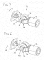
- Figure 6 shows the valve mechanism 22 with an actuator 100 which controls movement of the mounting body 58 to close either one of the inlets 44, 46 with the respective valve body 52, 54.
- the actuator 100 and the mounting body 58 are located outside of valve chamber 40 and in the area of the filter outlet 14.
- the actuator 100 can be operated directly by a driver of the vehicle and/or may be operated automatically (e.g. in response to a signal received from suitable sensors).
- a similar actuator to that at 100 is suitably used to control movement of the two links 59a, 59b in the embodiment of Fig. 3 , with the links 59a, 59b and actuator again being located outside of the valve chamber 40 and in the area of the filter outlet 14.
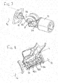
- joining body 56 may be a single piece, as shown in Figure 8 particularly, it may comprise two or more joining body parts 56A, 56B extending substantially parallel to each other between the first and second valve bodies 52, 54, optionally with cross-bracing between (not shown), in order to provide a rigid connection whilst reducing weight.
- the valve mechanism 22 has a valve chamber 40 with a fluid outlet 42 and first and second fluid inlets 44, 46.
- Each fluid inlet 44, 46 has a respective valve seat 48, 50 disposed on the exterior of the valve chamber around the inlet.
- Each fluid inlet 44, 46 also has a respective valve body 52, 54 movable into engagement with the respective valve seat to close the inlet.
- the first and second valve bodies 52, 54 are rigidly connected by a joining body 56 which extends through the fluid inlets 44, 46 and has a length greater than the separation of the valve seats, such that one fluid inlet is opened by the closing of the other.
Landscapes
- Engineering & Computer Science (AREA)
- Mechanical Engineering (AREA)
- General Engineering & Computer Science (AREA)
- Physics & Mathematics (AREA)
- Thermal Sciences (AREA)
- Filtering Of Dispersed Particles In Gases (AREA)
Abstract
Description
- The present invention relates to an air treatment apparatus and a valve mechanism for use in the same, in particular an air treatment apparatus for an operator environment or cab of an agricultural vehicle or a similar vehicle.
- Agricultural vehicles are known to operate in environments in which many different kinds of particulate or contaminant are present. This creates a requirement for filtration of the air for operators of such vehicles when in use. The particulates may be of different sizes and of different natures, for example larger particulates such as dust, pollen and the like and smaller contaminants such as fumes, aerosols and vapours.
- It is known to provide separate air filters to provide selective filtering of the air supply to a vehicle operator. For example a first filter may be used when the predominant contaminant in the working environment of the agricultural vehicle is relatively large (for example dust stirred up when traversing a field) and a second filter is used when the predominant contaminant in the working environment is relatively small (for example when applying a herbicide, pesticide or similar).
- Also, legislation in various countries now requires the use of filters of a particular rating to filter out particular contaminants from the air introduced into the operator environment or cabin of the agricultural vehicle. For example in the EU, EU Standard EN 15695 provides for four categories of filter for cabin protection, where
Category 2 protects only against dust but does not protect against aerosols and vapours,Category 3 protects against dust and aerosol, but not vapours andCategory 4 protects against dust, aerosols and vapours. In this context,Category 3 filters tend to be more expensive thanCategory 2 filters, withCategory 4 being most expensive. Accordingly, it is beneficial to the working life of the higher rated filters if they can be cleaned rather than replaced. It is a further advantage if such filters can be cleaned when in service on the agricultural vehicle rather than being removed while being cleaned (requiring replacement during cleaning or enforced downtime of the agricultural vehicle). - The present applicants International patent application
WO2019/120902 describes an air filtration apparatus having two filters in parallel, with a valve mechanism arranged to connect either one to an HVAC (heating, ventilation, air-conditioning) system whilst the other is being cleaned. There is a need for a suitable robust design of valve mechanism for such a system. - In accordance with a first aspect of the invention there is provided a valve mechanism for an air treatment apparatus, the mechanism comprising a valve chamber having a fluid outlet and first and second fluid inlets, wherein each fluid inlet has a respective valve seat disposed on the exterior of the valve chamber around the inlet, wherein each fluid inlet has a respective valve body movable into engagement with the respective valve seat to close the inlet, and wherein the first and second valve bodies are rigidly connected by a joining body which extends through the fluid inlets and has a length greater than the separation of the valve seats. This arrangement provides a simple and robust construction where movement of the joining body to bring one of the valve bodies into engagement with its respective valve seat, thereby closing that inlet, simultaneously acts to open the other inlet.
- The valve mechanism joining body may be substantially straight, with the valve seats lying in substantially parallel planes. The joining body may be a single piece, or may comprise two or more joining body parts extending substantially parallel to each other between the first and second valve bodies.
- The valve mechanism may further comprise an actuator connected to one of the valve bodies by a linkage, which actuator is operable to move the valve body into engagement with the respective valve seat, wherein the linkage and actuator are located outside of the valve chamber, preferably in an area of a filter device outlet.
- Preferably, the joining body is curved and each of the valve bodies extends substantially perpendicularly from a respective end of the joining body. In such an arrangement, the joining body may define an arc about an axis of rotation with the valve seats lying in respective planes, which planes intersect on a line substantially coincident with the axis of rotation, and the mechanism may further comprise a mounting body having a first end attached to one of the valve bodies and a second end pivotably attached to the valve chamber at or close to the axis of rotation. The mounting body and an actuator operable to move the mounting body are preferably located outside of the valve chamber, in an area of a filter device outlet.
- In accordance with a further aspect of the invention there is provided an air treatment apparatus for an operator environment of an agricultural vehicle in which air to be filtered is drawn into an air filtration system, filtered and directed to an agricultural vehicle HVAC system, which HVAC system comprises an inlet plenum, a blower, other HVAC components and an outlet to the operator environment;
wherein the air filtration system comprises;
at least one external inlet;
a first filtration device having a first relatively coarser level of filtration located between the external inlet and the HVAC inlet plenum;
a second filtration device having a second relatively finer level of filtration located between the external inlet or a further external inlet and the HVAC inlet plenum;
an air filtration system blower connected to the HVAC inlet plenum; and
a valve mechanism according to the first aspect of the invention, the valve mechanism having its first input connected to an output of the first filtration device, its second input connected to an output of the second filtration device, and its output connected to the inlet plenum of the HVAC system such that in use an air flow is directed from one or the other of the filtration devices to the HVAC inlet plenum. - Preferably, the air treatment apparatus further comprises a bypass connected at a second end adjacent the second filtration device such that in use when the valve mechanism connects the first filtration device to the HVAC inlet plenum a portion of an air flow through the air treatment apparatus is redirected to purge the second filtration device.
- There are two advantages of this arrangement. Firstly, the under pressure provided by the blowers sucks the valve mechanism, especially the valve bodies, against the fluid inlets and therefore helps to achieve an air tightness between the valve chamber and the filter outlet area. Secondly, as the valve chamber needs to be absolutely air tight to prevent drawing of contaminated air into the cabin, the mounting body or linkage is not placed in the valve chamber but in the filter outlet area. Therefore it is not needed to seal the mounting body or linkage because the filter outlet area belongs to the not sealed ambient area.
- Embodiments of the present invention will now be described by way of example only, and with reference to the accompanying drawings, in which:
-
Figure 1 shows a schematic view of a first embodiment of an air filtration apparatus in a first operating condition; -
Figure 2 shows a schematic view of the air filtration apparatus ofFigure 1 in a second operating condition; -
Figure 3 shows a schematic view of a first embodiment of valve mechanism used in the apparatus ofFigs. 1 and 2 , withFigure 3A showing an alternate arrangements of valve seat; -
Figure 4 is a schematic representation of a second embodiment of valve mechanism for use in the apparatus ofFigs. 1 and 2 ; and -
Figures 5 to 8 are perspective views, with some components omitted, of the second embodiment of valve mechanism. - The invention will now be described in the following detailed description with reference to the drawings, wherein preferred embodiments are described in detail to enable practice of the invention. Although the invention is described with reference to these specific preferred embodiments, it will be understood that the invention is not limited to these preferred embodiments. But to the contrary, the invention includes numerous alternatives, modifications and equivalents as will become apparent from consideration of the following detailed description.
- With reference to
Figures 1 and 2 , a schematic view of a first embodiment of an air filtration apparatus is shown comprising an air filtration system 2 (to the left of the dashed line 3) connected to an HVAC system 4 (to the right of the dashed line 3) for an operator environment or cabin of an agricultural vehicle. - An
external inlet 6 is shown feeding a first vent or duct 8 and a second vent orduct 10 by which air to be filtered is drawn into the filtration system. In an alternative embodiment (not shown) the first and second vents orducts 8, 10 may be provided with individual external inlets. Theexternal inlet 6 may conveniently be located in a roof housing of the cabin of the agricultural vehicle. - The first vent or duct 8 is directed to a
first filtration device 12 having a first relatively coarser level of filtration. Thefirst filtration device 12 is conveniently suitable for extracting dust particles and the like from the externally fed air. By way of example, this may be aCategory 2 dust filter. Thefirst filtration device 12 is provided with anoutlet 14. Theoutlet 14 is connected to a first inlet side of a valve mechanism 22 (described in further detail below with reference toFigures 3 to 7 ). - The second vent or
duct 10 is directed to asecond filtration device 16 having a second relatively finer level of filtration. Thesecond filtration device 16 is conveniently suitable for extracting dust, aerosols, vapour and the like from the externally fed air. By way of example, this may be aCategory 4 filter. Thesecond filtration device 16 is provided with anoutlet 18. An air filtration system blower 20, conveniently a fresh air blower, is associated with thesecond filtration device 16. The airfiltration system blower 20 is provided with an inlet connected to theoutlet 18 of thesecond filtration device 16 and an outlet connected to a second inlet side of thevalve mechanism 22. - The
valve mechanism 22 is provided with anoutlet conduit 24. The valve mechanism allows air flow from thesecond filtration device 16 to theoutlet conduit 24 while isolating the first filtration device 12 (as inFig. 1 ) or, alternatively allows air flow from thefirst filtration device 12 to theoutlet conduit 24 while isolating the second filtration device 16 (as inFig. 2 ). - The
valve mechanism 22 may be operated by any convenient means, for example automatically following a suitable signal received from a suitable sensor, automatically following actuation of a suitable device for example a sprayer, or by the direct action of a driver actuating suitable means within the cab. - In
Figures 1 and 2 theoutlet conduit 24 is connected to an inlet plenum of the HVAC system and in particular connects theoutlet conduit 24 to ablower 26 of the HVAC system ('HVAC system blower'). - The HVAC system typically includes
additional components 28 downstream of theblower 26, such as by way of example a evaporator and a heater. TheHVAC blower 26 is provided with a connectingconduit 30 to direct the air flow through the other components before delivery to the cabin by way of a cabinair supply duct 32. - A first end of a bypass channel or
passage 34 is connected to the connectingconduit 30. A second end of the bypass channel orpassage 34 is located between thesecond filtration device 16 and the associated airfiltration system blower 20. - A further air recirculation path is provided by a conduit (not shown) extending between the cabin and the
outlet conduit 24. - The typical operating position of the
valve mechanism 22 is that shown inFigure 2 , with the inlet air being drawn through the coarser (and cheaper)filter 12. However, when there is a need to extract aerosols, vapour and the like the system is switched to the configuration shown inFigure 1 . - To adopt the configuration shown in
Figure 1 , thevalve mechanism 22 is moved to the position shown and the airfiltration system blower 20 is also actuated. Air is drawn into the air filtration system through the second vent or duct 10 (arrow A) and drawn through thesecond filtration device 16 to remove dust, aerosols, vapour and the like entrained in the air. The air is directed through thevalve mechanism 22 to theoutlet conduit 24 and then drawn by theHVAC system blower 26 into the HVAC system and onward to the cabin air supply duct 32 (arrow B). In this position, thevalve mechanism 22 prevents communication between thefirst filtration device 12 and theHVAC blower 26. A first volume of underpressure (low pressure) is formed between thesecond filtration device 16 and the airfiltration system blower 20. Since theHVAC blower 26 is stronger than the airfiltration system blower 20, a second volume of underpressure is created between the airfiltration system blower 20 and theHVAC blower 26. - Due to an overpressure created in this situation on the HVAC system side, some of the air drawn into the HVAC system will recirculate through the bypass 34 (arrow C) into the region between the
second filtration device 16 and the airfiltration system blower 20 to mix with the freshly filtered air from thesecond filtration device 16 before being drawn by the airfiltration system blower 20 toward the HVAC blower. - Once the need to extract aerosols, vapour and the like has passed, the
valve mechanism 22 is caused to adopt the position shown inFigure 2 (the airfiltration system blower 20 is also deactivated). In this position, thevalve mechanism 22 prevents air flowing from thesecond filtration device 16 past the airfiltration system blower 20 to the inlet plenum of theHVAC blower 26. - Air is drawn into the air filtration system through the first vent or duct 8 (arrow A) and directed through the
first filtration device 12 to remove dust and the like entrained in the air. The air passes through thevalve mechanism 22 to theoutlet conduit 24 and most is then drawn by theHVAC system blower 26 into the HVAC system and out through the cabin air supply duct 32 (arrow B). - In addition, again due to the overpressure a portion of the air drawn into the HVAC system is drawn or recirculated through the bypass channel or passage 34 (arrow C) to the region between the
second filtration unit 16 and the airfiltration system blower 20, where, due to sealing of the airfiltration system blower 20 in its inactive state, the recirculated air is directed back through thesecond filtration device 16, thereby removing trapped dust, vapour and aerosol particles and the like from thesecond filtration device 16 and directing these back out through vent orduct 10. - This has as an advantage that the air filtered by the
first filtration device 12 is used to clean thesecond filtration device 16. It can be seen that thesecond filtration device 16 is being cleaned whenever thefirst filtration device 12 is in operation. It is a further advantage, with thefirst filtration device 12 connected to the HVAC system and the airfiltration system blower 20 associated with thesecond filtration device 16 inactive, that the use of the portion of the treated air to clean thesecond filtration device 16 results in a gentler cleaning action than if the air filtration system blower associated with thesecond filtration device 16 is reversed to drive air back through thesecond filtration device 16. This results in a prolonged life for thesecond filtration device 16. - As described in the above-mentioned International patent application
WO2019/120902 , variations on the layout ofFigures 1 and 2 are possible. In a first variant, the airfiltration system blower 20 is downstream of thevalve mechanism 22, coupled to the inlet plenum of theHVAC blower 26. In a second variant, an outlet of the airfiltration system blower 20 directs air through the bypass channel or passage 34 (arrow C) to the region between thesecond filtration unit 16 and inlet to the airfiltration system blower 20. -
Figure 3 represents a first embodiment of thevalve mechanism 22. The mechanism comprises avalve chamber 40 having afluid outlet 42 coupled with theoutlet conduit 24, and first 44 and second 46 fluid inlets respectively coupled with thefilter device outlets fluid inlets respective valve seat fluid inlets respective valve body respective valve seat second valve bodies fluid inlets body 56 has a length greater than the separation of the valve seats 48, 50 so that closing of one of theinlets 44 results in the opening of the other 46. - An actuator (not shown) moves the
valve bodies body 56 by means of a linkage consisting of twolinks valve chamber 40, in the area of thefilter device outlet 14. The twolinks link 59a pivotably connected to the housing ofchamber 40 and the other 59b pivotably connected to thevalve body 54. - The valve seating in the embodiment of
Figure 3 may comprise a chamfered portion of thevalve body 52 cooperating with a corresponding chamferedrecess 48 in the body of thevalve chamber 40 as shown, but it will be understood that other arrangements are possible. For example, as shown inFigure 3A , thevalve body 54 andvalve chamber 40 may present substantially flat and parallel surfaces and thevalve seat 50 may be simply provided by the two surfaces meeting, or additional sealing means such as a rubber seal, grommet or washer 50A may be provided around theopening 46. -
Figures 4 to 8 illustrate an alternative embodiment of thevalve mechanism 22. Those components performing the same function as in theFig. 3 embodiment are identified by the same reference numerals. In this embodiment, the joiningbody 56 is curved and each of thevalve bodies body 56 defines an arc about an axis of rotation R and the valve seats 48, 50 lie in respective planes, which planes intersect on a line substantially coincident with the axis of rotation. Supporting the valve bodies and joining body there is a mountingbody 58 having a first end attached to one of thevalve bodies valve chamber 40, close to the axis of rotation R, but outside of thechamber 40 and in theoutlet area 14 of the first filtration device. As before, movement of one of thevalve bodies 52 into engagement with itsrespective valve seat 48 to close theinlet 44 will cause the other of thevalve bodies 54 to disengage from itsrespective valve seat 50 and open theother inlet 46. - The valve seating configurations may take various forms as described above. Also, it will be understood that the plane in which the respective valve seats lie may not be aligned with the axis of rotation R. Such planes may be angled with respect to the axis R if the valves bodies are similarly angled such that they effect a seal when the two are brought into conjunction.
-
Figure 6 shows thevalve mechanism 22 with anactuator 100 which controls movement of the mountingbody 58 to close either one of theinlets respective valve body actuator 100 and the mountingbody 58 are located outside ofvalve chamber 40 and in the area of thefilter outlet 14. Theactuator 100 can be operated directly by a driver of the vehicle and/or may be operated automatically (e.g. in response to a signal received from suitable sensors). - A similar actuator to that at 100 is suitably used to control movement of the two
links Fig. 3 , with thelinks valve chamber 40 and in the area of thefilter outlet 14. - Whilst the joining
body 56 may be a single piece, as shown inFigure 8 particularly, it may comprise two or more joining body parts 56A, 56B extending substantially parallel to each other between the first andsecond valve bodies - In the foregoing the applicants have described a
valve mechanism 22 provided for an air treatment apparatus, together with an air treatment apparatus employing the same. Thevalve mechanism 22 has avalve chamber 40 with afluid outlet 42 and first and secondfluid inlets fluid inlet respective valve seat fluid inlet respective valve body second valve bodies body 56 which extends through thefluid inlets - From reading of the present disclosure, other modifications will be apparent to those skilled in the art and the scope of the invention is limited only by the following claims.
Claims (13)
wherein the air filtration system comprises;
at least one external inlet (6);
a first filtration device (12) having a first relatively coarser level of filtration located between the external inlet (6) and the HVAC inlet plenum;
a second filtration device (14) having a second relatively finer level of filtration located between the external inlet (6) or a further external inlet and the HVAC inlet plenum;
an air filtration system blower (20) connected to the HVAC inlet plenum; and
a valve mechanism (22) as claimed in any preceding claim, the valve mechanism having its first input (44) connected to an output (14) of the first filtration device (12), its second input (46) connected to an output (18) of the second filtration device (16), and its output (42, 24) connected to the inlet plenum of the HVAC system such that in use an air flow is directed from one or the other of the filtration devices to the HVAC inlet plenum.
Applications Claiming Priority (1)
| Application Number | Priority Date | Filing Date | Title |
|---|---|---|---|
| GBGB1814571.4A GB201814571D0 (en) | 2018-09-07 | 2018-09-07 | Air treatment apparatus and valve mechanism |
Publications (1)
| Publication Number | Publication Date |
|---|---|
| EP3620317A1 true EP3620317A1 (en) | 2020-03-11 |
Family
ID=63921070
Family Applications (1)
| Application Number | Title | Priority Date | Filing Date |
|---|---|---|---|
| EP19195325.6A Withdrawn EP3620317A1 (en) | 2018-09-07 | 2019-09-04 | Air treatment apparatus and valve mechanism |
Country Status (2)
| Country | Link |
|---|---|
| EP (1) | EP3620317A1 (en) |
| GB (1) | GB201814571D0 (en) |
Cited By (1)
| Publication number | Priority date | Publication date | Assignee | Title |
|---|---|---|---|---|
| EP4008574A1 (en) * | 2020-12-03 | 2022-06-08 | AGCO International GmbH | Air treatment system |
Citations (5)
| Publication number | Priority date | Publication date | Assignee | Title |
|---|---|---|---|---|
| CN204677814U (en) * | 2014-12-31 | 2015-09-30 | 深圳市冠瑞达能源装备有限公司 | A kind of selection atmospheric valve |
| WO2015159248A1 (en) * | 2014-04-16 | 2015-10-22 | Denso Thermal Systems S.P.A. | Cabin pressurazation system for agricultural machines, having a filteration system |
| WO2016005401A1 (en) * | 2014-07-09 | 2016-01-14 | Cnh Industrial Italia S.P.A. | Selective filtration level air treatment system. |
| EP3173266A1 (en) * | 2015-11-24 | 2017-05-31 | CNH Industrial France | Process of operating the air conditioning system of a cab of a machine |
| WO2019120902A1 (en) | 2017-12-20 | 2019-06-27 | Agco International Gmbh | Air treatment apparatus for an agricultural vehicle |
-
2018
- 2018-09-07 GB GBGB1814571.4A patent/GB201814571D0/en not_active Ceased
-
2019
- 2019-09-04 EP EP19195325.6A patent/EP3620317A1/en not_active Withdrawn
Patent Citations (5)
| Publication number | Priority date | Publication date | Assignee | Title |
|---|---|---|---|---|
| WO2015159248A1 (en) * | 2014-04-16 | 2015-10-22 | Denso Thermal Systems S.P.A. | Cabin pressurazation system for agricultural machines, having a filteration system |
| WO2016005401A1 (en) * | 2014-07-09 | 2016-01-14 | Cnh Industrial Italia S.P.A. | Selective filtration level air treatment system. |
| CN204677814U (en) * | 2014-12-31 | 2015-09-30 | 深圳市冠瑞达能源装备有限公司 | A kind of selection atmospheric valve |
| EP3173266A1 (en) * | 2015-11-24 | 2017-05-31 | CNH Industrial France | Process of operating the air conditioning system of a cab of a machine |
| WO2019120902A1 (en) | 2017-12-20 | 2019-06-27 | Agco International Gmbh | Air treatment apparatus for an agricultural vehicle |
Cited By (1)
| Publication number | Priority date | Publication date | Assignee | Title |
|---|---|---|---|---|
| EP4008574A1 (en) * | 2020-12-03 | 2022-06-08 | AGCO International GmbH | Air treatment system |
Also Published As
| Publication number | Publication date |
|---|---|
| GB201814571D0 (en) | 2018-10-24 |
Similar Documents
| Publication | Publication Date | Title |
|---|---|---|
| EP3727914B1 (en) | Air treatment apparatus | |
| US20210086582A1 (en) | Air treatment apparatus for an agricultural vehicle | |
| US11787268B2 (en) | Air treatment apparatus | |
| US8382870B2 (en) | Self-cleaning air filter | |
| EP4008574B1 (en) | Air treatment system | |
| US10538140B2 (en) | Cabin pressurization system for agricultural machines, having a filtration system | |
| CN101722816A (en) | Automotive ventilation system | |
| US4469490A (en) | Method and apparatus for cleaning air entering the cab of a vehicle | |
| AU2015286813C1 (en) | Air treatment system with pressure balance | |
| US7338357B2 (en) | Filter purge control for HVAC fixed air circulation system | |
| US11820200B2 (en) | Air treatment apparatus | |
| EP3166810B1 (en) | Selective filtration level air treatment system. | |
| US6217439B1 (en) | Climate control unit | |
| CA1088041A (en) | Filter system for agricultural aircraft | |
| US8272932B2 (en) | Ventilation system for a cab of an agricultural machine involved in spraying operations, and an agricultural machine fitted with such a system | |
| CA2219609A1 (en) | Air intake system for an off-highway machine | |
| GB2292883A (en) | Odour absorbing system for a vacuum cleaner | |
| AU2022203520A1 (en) | Air mixing plenum, system and method | |
| NZ788629A (en) | Air mixing plenum, system and method | |
| CN116512861A (en) | Particulate matter and/or winged insect purifying system and automobile with purifying system | |
| CN117412876A (en) | Vehicle heating, ventilation and air conditioning systems | |
| KR910700091A (en) | Collecting system with off-line filter cleaning |
Legal Events
| Date | Code | Title | Description |
|---|---|---|---|
| PUAI | Public reference made under article 153(3) epc to a published international application that has entered the european phase |
Free format text: ORIGINAL CODE: 0009012 |
|
| STAA | Information on the status of an ep patent application or granted ep patent |
Free format text: STATUS: THE APPLICATION HAS BEEN PUBLISHED |
|
| AK | Designated contracting states |
Kind code of ref document: A1 Designated state(s): AL AT BE BG CH CY CZ DE DK EE ES FI FR GB GR HR HU IE IS IT LI LT LU LV MC MK MT NL NO PL PT RO RS SE SI SK SM TR |
|
| AX | Request for extension of the european patent |
Extension state: BA ME |
|
| STAA | Information on the status of an ep patent application or granted ep patent |
Free format text: STATUS: REQUEST FOR EXAMINATION WAS MADE |
|
| 17P | Request for examination filed |
Effective date: 20200911 |
|
| RBV | Designated contracting states (corrected) |
Designated state(s): AL AT BE BG CH CY CZ DE DK EE ES FI FR GB GR HR HU IE IS IT LI LT LU LV MC MK MT NL NO PL PT RO RS SE SI SK SM TR |
|
| STAA | Information on the status of an ep patent application or granted ep patent |
Free format text: STATUS: THE APPLICATION IS DEEMED TO BE WITHDRAWN |
|
| 18D | Application deemed to be withdrawn |
Effective date: 20200912 |