EP3620090B1 - Elevated toilet seat assembly - Google Patents
Elevated toilet seat assembly Download PDFInfo
- Publication number
- EP3620090B1 EP3620090B1 EP19196186.1A EP19196186A EP3620090B1 EP 3620090 B1 EP3620090 B1 EP 3620090B1 EP 19196186 A EP19196186 A EP 19196186A EP 3620090 B1 EP3620090 B1 EP 3620090B1
- Authority
- EP
- European Patent Office
- Prior art keywords
- toilet seat
- toilet
- guard
- elevated
- seat assembly
- Prior art date
- Legal status (The legal status is an assumption and is not a legal conclusion. Google has not performed a legal analysis and makes no representation as to the accuracy of the status listed.)
- Active
Links
Images

Classifications
-
- A—HUMAN NECESSITIES
- A47—FURNITURE; DOMESTIC ARTICLES OR APPLIANCES; COFFEE MILLS; SPICE MILLS; SUCTION CLEANERS IN GENERAL
- A47K—SANITARY EQUIPMENT; ACCESSORIES THEREFOR, e.g. TOILET ACCESSORIES
- A47K13/00—Seats or covers for all kinds of closets
- A47K13/005—Auxiliary or portable seats
-
- A—HUMAN NECESSITIES
- A47—FURNITURE; DOMESTIC ARTICLES OR APPLIANCES; COFFEE MILLS; SPICE MILLS; SUCTION CLEANERS IN GENERAL
- A47K—SANITARY EQUIPMENT; ACCESSORIES THEREFOR, e.g. TOILET ACCESSORIES
- A47K13/00—Seats or covers for all kinds of closets
- A47K13/02—Seats or covers for all kinds of closets of plastic materials
-
- A—HUMAN NECESSITIES
- A47—FURNITURE; DOMESTIC ARTICLES OR APPLIANCES; COFFEE MILLS; SPICE MILLS; SUCTION CLEANERS IN GENERAL
- A47K—SANITARY EQUIPMENT; ACCESSORIES THEREFOR, e.g. TOILET ACCESSORIES
- A47K13/00—Seats or covers for all kinds of closets
- A47K13/12—Hinges
-
- A—HUMAN NECESSITIES
- A47—FURNITURE; DOMESTIC ARTICLES OR APPLIANCES; COFFEE MILLS; SPICE MILLS; SUCTION CLEANERS IN GENERAL
- A47K—SANITARY EQUIPMENT; ACCESSORIES THEREFOR, e.g. TOILET ACCESSORIES
- A47K13/00—Seats or covers for all kinds of closets
- A47K13/14—Protecting covers for closet seats
-
- A—HUMAN NECESSITIES
- A47—FURNITURE; DOMESTIC ARTICLES OR APPLIANCES; COFFEE MILLS; SPICE MILLS; SUCTION CLEANERS IN GENERAL
- A47K—SANITARY EQUIPMENT; ACCESSORIES THEREFOR, e.g. TOILET ACCESSORIES
- A47K13/00—Seats or covers for all kinds of closets
- A47K13/24—Parts or details not covered in, or of interest apart from, groups A47K13/02 - A47K13/22
-
- A—HUMAN NECESSITIES
- A47—FURNITURE; DOMESTIC ARTICLES OR APPLIANCES; COFFEE MILLS; SPICE MILLS; SUCTION CLEANERS IN GENERAL
- A47K—SANITARY EQUIPMENT; ACCESSORIES THEREFOR, e.g. TOILET ACCESSORIES
- A47K17/00—Other sanitary equipment not covered by the other groups of this subclass ; Holders for toilet brushes
- A47K17/02—Body supports, other than seats, for closets, e.g. handles, back-rests, foot-rests; Accessories for closets, e.g. reading tables
- A47K17/026—Armrests mounted on or around the toilet
-
- A—HUMAN NECESSITIES
- A47—FURNITURE; DOMESTIC ARTICLES OR APPLIANCES; COFFEE MILLS; SPICE MILLS; SUCTION CLEANERS IN GENERAL
- A47K—SANITARY EQUIPMENT; ACCESSORIES THEREFOR, e.g. TOILET ACCESSORIES
- A47K13/00—Seats or covers for all kinds of closets
- A47K13/04—Buffers for seats
Definitions
- the present invention relates to toilet seat assemblies, and more particularly to elevated toilet seat assemblies that assist in helping a person sit down on and stand up from a toilet.
- DE10136216 discloses a toilet for use by disabled people has seat whose inner and outer walls are linked by partitions, on which supporting bars whose heights can be adjusted are mounted.
- US5412815 discloses a raised toilet seat formed from a plastic material as a single member by injection molding.
- the present invention comprises the following features:
- An elevated toilet seat assembly for a toilet comprising;
- FIGS. 1 and 2 illustrate an elevated toilet seat assembly 10 coupled to a toilet 15.
- the toilet seat assembly 10 includes a toilet seat 20 pivotably coupled to a hinge post 25 about an axis 30 between a first position ( FIG. 1 ) and a second position ( FIG. 2 ).
- the first position is a raised or upright position.
- the second position is a lowered or in-use position when the toilet seat 20 engages a rim surface 32 of the toilet 15.
- the hinge post 25 includes two post members 35 that are coupled to a base 40 of the toilet 15.
- the hinge post 25 can be fixed to the base 40 by fasteners or selectively coupled to the base 40 by a quick-disconnect feature.
- the hinge post 25 can include one post member coupling the toilet seat 20 to the base 40.
- a height 45 of the hinge post 25 (i.e., a distance between the axis 30 and a bottom surface 50 of the hinge post 25; FIG. 4 ) is between about 3 inches (76.2 mm) and about 5 inches (127 mm). In some embodiments, the height 45 of the hinge post 25 is about 4 inches (101.6 mm).
- the illustrated toilet seat 20 is made of plastic. More particularly, the toilet seat 20 is injection molded as a single piece of solid plastic. As such, the below described features of the toilet seat 20 are formed in one injection molding process.
- the toilet seat 20 includes an upper portion 55 having a support surface 60 defined between an outer perimeter 65 and an inner perimeter 70 of the upper portion 55.
- the inner perimeter 70 is an inner seat edge of the upper portion 55 and defines a central or top opening 75 of the toilet seat 20.
- the upper portion 55 defines a maximum thickness 80 (e.g., a maximum height of the upper portion 55) between about 0.35 inches (8.89 mm) and about 0.85 inches (21.59 mm).
- the maximum thickness 80 is measured from the support surface 60 to a bottom surface 85 of the upper portion 55. In other embodiments, the maximum thickness 80 of the upper portion 55 is about 0.6 inches (15.24 mm). Furthermore, the upper portion 55 includes a protrusion 90 to couple with the hinge post 25 ( FIGS. 4 and 5 ).
- the toilet seat 20 also includes a lower portion 95 extending from the bottom surface 85 of the upper portion 55 ( FIG. 4 ).
- the lower portion 95 includes a shield or guard 100 having an upper edge 105 ( FIG. 3 and 5 ) defined by the inner perimeter 70 of the upper portion 55, a lower edge or inner guard edge 110 opposite the upper edge 105 defining a bottom opening 106 of the toilet seat 20, and an inner surface 115 and an outer surface 120 extending between the upper edge 105 and the lower edge 110.
- the guard 100 defines a height 125 of about 2.12 inches (53.85 mm) to about 2.62 inches (66.55 mm). In other embodiments, the height 125 is about 2.375 inches (60.33 mm).
- the height 125 is measured from the upper edge 105 to the lower edge 110 of the guard 100.
- a ratio of the height 125 over the maximum thickness 80 of the upper portion 55 is between about 3 and about 6. In other embodiments, the ratio of the height 125 over the maximum thickness 80 of the upper portion 55 is about 4.
- the illustrated guard 100 tapers from the lower edge 110 to the upper edge 105.
- the guard 100 includes a nonlinear taper (e.g., a curved taper) that gradually and continuously tapers from the lower edge 110 to the upper edge 105. In other embodiments, the guard 100 can include a linear taper.
- the guard 100 can be a stepped taper and/or include portions without any taper and other portions with angled tapers.
- the guard 100 can include a discontinuous taper from the lower edge 110 to the upper edge 105.
- the illustrated guard 100 continuously and completely surrounds the central opening 75 of the upper portion 55 ( FIG. 5 ), and the guard 100 does not extend outwardly beyond the outer perimeter 65 of the upper portion 55 ( FIGS. 4 and 5 ).
- the lower edge 110 is positioned between the outer perimeter 65 and the inner perimeter 70 of the upper portion 55 as shown in FIG. 5 .
- a longitudinal plane 130 (e.g., a first plane) is oriented perpendicular to the axis 30 and extends through the top opening 75 and the bottom opening 106 of the toilet seat 20.
- the longitudinal plane 130 is also oriented perpendicular to the rim surface 32 of the toilet 15 and extends through the top opening 75 and the bottom opening 106 when the toilet seat 20 is in the in-use position.
- FIG. 5 shows one position of the longitudinal plane 130 (e.g., extending centrally through the top and bottom openings 75, 160), but the longitudinal plane 130 can also be positioned differently (e.g., right or left of the longitudinal plane 130 as illustrated in FIG.
- the guard 100 also includes a lateral plane 155 (e.g., a second plane; FIG. 5 ) oriented parallel to the axis 30 and oriented perpendicular to the rim surface 32 of the toilet 15 when the toilet seat 20 is in the in-use position.
- the lateral plane 155 also extends through the top opening 75 and the bottom opening 106.
- FIG. 5 shows one position of the lateral plane 155 (e.g., extending centrally through the top and bottom openings 75, 160), but the lateral plane 155 can also be positioned differently (e.g., above or below the lateral plane 155 as illustrated in FIG.
- a third distance 160 which is measured within the lateral plane 155 between opposing points 165 on the upper edge 105, is less than a fourth distance 170, which is measured within the lateral plane 155 between opposing points 175 on the lower edge 110.
- a maximum dimension of the upper edge 105 of the support surface 60 e.g., a distance separating points 140
- a maximum dimension of the lower edge 110 of the guard 100 e.g., a distance separating points 150
- the maximum dimension of the upper edge 105 and the lower edge 110 can be measured perpendicular to the axis 30. In other embodiments, the maximum dimension of the upper edge 105 and the lower edge 110 can be measured parallel to the axis 30 such that the maximum dimension of the upper edge 105 (e.g., a distance separating points 165) is less than the maximum dimension of the lower edge 110 (e.g., a distance separating points 175).
- a plurality of supports 180 extend outwardly from the outer surface 120 of the guard 100 toward the outer perimeter 65 of the upper portion 55.
- each support 180 extends from the outer surface 120 of the guard 100 substantially parallel to the axis 30.
- each support 180 extends along the entire height 125 of the guard 100 from the bottom surface 85 of the upper portion 55 to the lower edge 110 of the guard 100 ( FIG. 4 ).
- the height 125 of the guard 100 is generally the same height of the supports 180, which is greater than the maximum thickness 80 of the upper portion 55.
- at least one support 180 can extend a portion of the height 125 of the guard 100 (e.g., from a midway of the guard 100 to the lower edge 110).
- the supports 180 are formed within the foot print area of the upper portion 55 (i.e., the supports 180 do not extend outwardly beyond the outer perimeter 65 of the support surface 60).
- the illustrated supports 180 include two pairs of supports, with each pair positioned on opposite sides of the guard 100 and extending away from each other ( FIG. 5 ). In other embodiments, the supports 180 can include more or less than four supports and/or be arranged differently around the guard 100.
- the toilet seat 20 can include at least one support 180 that extends away/toward the protrusion 90 (extending transverse (e.g., non-parallel) to the axis 30).
- each support 180 includes a foot 185 positioned on one end of the support 180.
- each foot 185 extends below the lower edge 110 of the guard 100 ( FIG. 4 ).
- each foot 185 can be a separate member (e.g., a rubber foot) from the toilet seat 20 that can be coupled to the end of each support 180.
- the feet 185 provide a softer contact surface that reduces the possibility of marring or noisily engaging the toilet 15 during use.
- the toilet seat assembly 10 also includes two support handles or arms 190 for a person to stabilize themselves sitting down on the toilet seat 20, during use of the toilet seat 20, and/or standing up from the toilet seat 20.
- each arm 190 is tubular in construction and is fixed to a pair of supports 180.
- the arms 190 can be removably coupled to the toilet seat 20.
- the support handles 190 can be plastic injection molded with the toilet seat 20 as one component.
- the toilet seat assembly 10 can omit the support handles 190.
- the illustrated toilet seat assembly 10 also includes a lid 195 that is pivotably coupled to the hinge posts 25 and the protrusion 90 about the axis 30 to selectively cover the central opening 75 of the toilet seat 20.
- the feet 185 of the supports 180 engage the rim surface 32 of the toilet 15 to support the toilet seat 20 at an elevated height above the rim surface 32. Accordingly, the bottom surface 85 of the upper portion 55 is positioned away from the rim surface 32 of the toilet 15 (e.g., the bottom surface 85 does not engage the rim surface 32).
- the support surface 60 of the toilet seat 20 is positioned between about 3 inches (76.2 mm) and about 5 inches (127 mm) above the rim surface 32 once the toilet seat 20 is in the in-use position. Accordingly, the elevated height of the support surface 60 assists in helping a person sit down on the support surface 60 or stand up from the support surface 60 before/after use.
- the guard 100 is operable to block waste from splashing out of the toilet 15 during use.
- the lower edge 110 is positioned above the rim surface 32 (e.g., the lower edge 110 does not extend below the rim surface 32 into the toilet 15).
- the feet 185 can be omitted so that the lower edge 110 of the guard 100 is positioned substantially level with the rim surface 32 when the supports 180 engage the rim surface 32.
- the toilet seat 20 is operably universal with many different types of toilets 15 (e.g., U.S. style round toilets, U.S. style elongated toilets, European style toilets, etc.).
Landscapes
- Health & Medical Sciences (AREA)
- Public Health (AREA)
- Epidemiology (AREA)
- General Health & Medical Sciences (AREA)
- Toilet Supplies (AREA)
Description
- The present invention relates to toilet seat assemblies, and more particularly to elevated toilet seat assemblies that assist in helping a person sit down on and stand up from a toilet.
DE10136216 discloses a toilet for use by disabled people has seat whose inner and outer walls are linked by partitions, on which supporting bars whose heights can be adjusted are mounted.US5412815 discloses a raised toilet seat formed from a plastic material as a single member by injection molding. - The present invention comprises the following features:
- An elevated toilet seat assembly for a toilet, the elevated toilet seat assembly comprising;
- a toilet seat configured to be pivotably coupled to the toilet about an axis, the toilet seat including
- a support surface having an inner top edge defining a top opening, the support surface configured to support a person on the toilet seat, and
- a guard extending below the support surface, the guard having an inner bottom edge defining a bottom opening of the toilet seat, the guard configured to block waste from splashing out of the toilet during use,
- wherein the guard tapers from the inner bottom edge of the guard toward the inner top edge of the support surface.
- Preferred embodiments are described in the dependent claims.
- Other aspects of the invention will become apparent by consideration of the detailed description and accompanying drawings.
-
-
FIG. 1 is a perspective view of an elevated toilet seat assembly according to an embodiment of the invention, the toilet seat assembly coupled to a toilet in a raised position. -
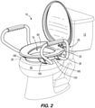
FIG. 2 is a perspective view of the elevated toilet seat assembly ofFIG. 1 in a lowered position. -
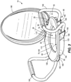
FIG. 3 is a perspective view of the elevated toilet seat assembly ofFIG. 1 . -
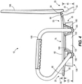
FIG. 4 is a side view of the elevated toilet seat assembly ofFIG. 3 . -
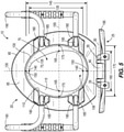
FIG. 5 is a bottom view of the elevated toilet seat assembly ofFIG. 3 . -
FIGS. 1 and2 illustrate an elevatedtoilet seat assembly 10 coupled to atoilet 15. Thetoilet seat assembly 10 includes atoilet seat 20 pivotably coupled to ahinge post 25 about anaxis 30 between a first position (FIG. 1 ) and a second position (FIG. 2 ). The first position is a raised or upright position. The second position is a lowered or in-use position when thetoilet seat 20 engages arim surface 32 of thetoilet 15. Thehinge post 25 includes twopost members 35 that are coupled to abase 40 of thetoilet 15. Thehinge post 25 can be fixed to thebase 40 by fasteners or selectively coupled to thebase 40 by a quick-disconnect feature. In other embodiments, thehinge post 25 can include one post member coupling thetoilet seat 20 to thebase 40. In the illustrated embodiment, aheight 45 of the hinge post 25 (i.e., a distance between theaxis 30 and abottom surface 50 of thehinge post 25;FIG. 4 ) is between about 3 inches (76.2 mm) and about 5 inches (127 mm). In some embodiments, theheight 45 of thehinge post 25 is about 4 inches (101.6 mm). - The illustrated
toilet seat 20 is made of plastic. More particularly, thetoilet seat 20 is injection molded as a single piece of solid plastic. As such, the below described features of thetoilet seat 20 are formed in one injection molding process. With reference toFIGS. 3 and4 , thetoilet seat 20 includes anupper portion 55 having asupport surface 60 defined between anouter perimeter 65 and an inner perimeter 70 of theupper portion 55. The inner perimeter 70 is an inner seat edge of theupper portion 55 and defines a central or top opening 75 of thetoilet seat 20. As best shown inFIG. 4 , theupper portion 55 defines a maximum thickness 80 (e.g., a maximum height of the upper portion 55) between about 0.35 inches (8.89 mm) and about 0.85 inches (21.59 mm). Themaximum thickness 80 is measured from thesupport surface 60 to abottom surface 85 of theupper portion 55. In other embodiments, themaximum thickness 80 of theupper portion 55 is about 0.6 inches (15.24 mm). Furthermore, theupper portion 55 includes aprotrusion 90 to couple with the hinge post 25 (FIGS. 4 and5 ). - The
toilet seat 20 also includes alower portion 95 extending from thebottom surface 85 of the upper portion 55 (FIG. 4 ). Thelower portion 95 includes a shield orguard 100 having an upper edge 105 (FIG. 3 and5 ) defined by the inner perimeter 70 of theupper portion 55, a lower edge orinner guard edge 110 opposite the upper edge 105 defining abottom opening 106 of thetoilet seat 20, and aninner surface 115 and anouter surface 120 extending between the upper edge 105 and thelower edge 110. Theguard 100 defines aheight 125 of about 2.12 inches (53.85 mm) to about 2.62 inches (66.55 mm). In other embodiments, theheight 125 is about 2.375 inches (60.33 mm). Theheight 125 is measured from the upper edge 105 to thelower edge 110 of theguard 100. As such, a ratio of theheight 125 over themaximum thickness 80 of theupper portion 55 is between about 3 and about 6. In other embodiments, the ratio of theheight 125 over themaximum thickness 80 of theupper portion 55 is about 4. The illustratedguard 100 tapers from thelower edge 110 to the upper edge 105. With reference toFIG. 4 , theguard 100 includes a nonlinear taper (e.g., a curved taper) that gradually and continuously tapers from thelower edge 110 to the upper edge 105. In other embodiments, theguard 100 can include a linear taper. In further embodiments, theguard 100 can be a stepped taper and/or include portions without any taper and other portions with angled tapers. In yet further embodiments, theguard 100 can include a discontinuous taper from thelower edge 110 to the upper edge 105. In addition, the illustratedguard 100 continuously and completely surrounds thecentral opening 75 of the upper portion 55 (FIG. 5 ), and theguard 100 does not extend outwardly beyond theouter perimeter 65 of the upper portion 55 (FIGS. 4 and5 ). For example, thelower edge 110 is positioned between theouter perimeter 65 and the inner perimeter 70 of theupper portion 55 as shown inFIG. 5 . - With continued reference to
FIG. 5 , a longitudinal plane 130 (e.g., a first plane) is oriented perpendicular to theaxis 30 and extends through the top opening 75 and the bottom opening 106 of thetoilet seat 20. As such, thelongitudinal plane 130 is also oriented perpendicular to therim surface 32 of thetoilet 15 and extends through the top opening 75 and the bottom opening 106 when thetoilet seat 20 is in the in-use position.FIG. 5 shows one position of the longitudinal plane 130 (e.g., extending centrally through the top andbottom openings 75, 160), but thelongitudinal plane 130 can also be positioned differently (e.g., right or left of thelongitudinal plane 130 as illustrated inFIG. 5 ) as long as thelongitudinal plane 130 is oriented perpendicular to theaxis 30. With continued reference toFIG. 5 , afirst distance 135, which is measured within thelongitudinal plane 130 betweenopposing points 140 on the upper edge 105, is less than asecond distance 145, which is measured within thelongitudinal plane 130 betweenopposing points 150 on thelower edge 110. - The
guard 100 also includes a lateral plane 155 (e.g., a second plane;FIG. 5 ) oriented parallel to theaxis 30 and oriented perpendicular to therim surface 32 of thetoilet 15 when thetoilet seat 20 is in the in-use position. Thelateral plane 155 also extends through the top opening 75 and the bottom opening 106.FIG. 5 shows one position of the lateral plane 155 (e.g., extending centrally through the top andbottom openings 75, 160), but thelateral plane 155 can also be positioned differently (e.g., above or below thelateral plane 155 as illustrated inFIG. 5 ) as long as thelateral plane 155 is oriented parallel to theaxis 30 and perpendicular to therim surface 32 when thetoilet seat 20 is in the in-use position. With continued reference toFIG. 5 , athird distance 160, which is measured within thelateral plane 155 betweenopposing points 165 on the upper edge 105, is less than afourth distance 170, which is measured within thelateral plane 155 betweenopposing points 175 on thelower edge 110. Stated another way, a maximum dimension of the upper edge 105 of the support surface 60 (e.g., a distance separating points 140) is less than a maximum dimension of thelower edge 110 of the guard 100 (e.g., a distance separating points 150). As such, in one embodiment, the maximum dimension of the upper edge 105 and thelower edge 110 can be measured perpendicular to theaxis 30. In other embodiments, the maximum dimension of the upper edge 105 and thelower edge 110 can be measured parallel to theaxis 30 such that the maximum dimension of the upper edge 105 (e.g., a distance separating points 165) is less than the maximum dimension of the lower edge 110 (e.g., a distance separating points 175). - With reference to
FIG. 5 , a plurality ofsupports 180 extend outwardly from theouter surface 120 of theguard 100 toward theouter perimeter 65 of theupper portion 55. In other words, eachsupport 180 extends from theouter surface 120 of theguard 100 substantially parallel to theaxis 30. In the illustrated embodiment, eachsupport 180 extends along theentire height 125 of theguard 100 from thebottom surface 85 of theupper portion 55 to thelower edge 110 of the guard 100 (FIG. 4 ). For example, theheight 125 of theguard 100 is generally the same height of thesupports 180, which is greater than themaximum thickness 80 of theupper portion 55. In other embodiments, at least onesupport 180 can extend a portion of theheight 125 of the guard 100 (e.g., from a midway of theguard 100 to the lower edge 110). Thesupports 180 are formed within the foot print area of the upper portion 55 (i.e., thesupports 180 do not extend outwardly beyond theouter perimeter 65 of the support surface 60). The illustrated supports 180 include two pairs of supports, with each pair positioned on opposite sides of theguard 100 and extending away from each other (FIG. 5 ). In other embodiments, thesupports 180 can include more or less than four supports and/or be arranged differently around theguard 100. For example, thetoilet seat 20 can include at least onesupport 180 that extends away/toward the protrusion 90 (extending transverse (e.g., non-parallel) to the axis 30). In the illustrated embodiment, eachsupport 180 includes afoot 185 positioned on one end of thesupport 180. Eachfoot 185 extends below thelower edge 110 of the guard 100 (FIG. 4 ). In other embodiments, eachfoot 185 can be a separate member (e.g., a rubber foot) from thetoilet seat 20 that can be coupled to the end of eachsupport 180. In such embodiments, thefeet 185 provide a softer contact surface that reduces the possibility of marring or noisily engaging thetoilet 15 during use. - As shown in
FIGS. 3-5 , thetoilet seat assembly 10 also includes two support handles orarms 190 for a person to stabilize themselves sitting down on thetoilet seat 20, during use of thetoilet seat 20, and/or standing up from thetoilet seat 20. In particular, eacharm 190 is tubular in construction and is fixed to a pair ofsupports 180. In other embodiments, thearms 190 can be removably coupled to thetoilet seat 20. In some embodiments, the support handles 190 can be plastic injection molded with thetoilet seat 20 as one component. In further embodiments, thetoilet seat assembly 10 can omit the support handles 190. - The illustrated
toilet seat assembly 10 also includes alid 195 that is pivotably coupled to the hinge posts 25 and theprotrusion 90 about theaxis 30 to selectively cover thecentral opening 75 of thetoilet seat 20. - As the
toilet seat 20 is moved from the upright position (FIG. 1 ) to the in-use position (FIG. 2 ), thefeet 185 of thesupports 180 engage therim surface 32 of thetoilet 15 to support thetoilet seat 20 at an elevated height above therim surface 32. Accordingly, thebottom surface 85 of theupper portion 55 is positioned away from therim surface 32 of the toilet 15 (e.g., thebottom surface 85 does not engage the rim surface 32). In the illustrated embodiment, thesupport surface 60 of thetoilet seat 20 is positioned between about 3 inches (76.2 mm) and about 5 inches (127 mm) above therim surface 32 once thetoilet seat 20 is in the in-use position. Accordingly, the elevated height of thesupport surface 60 assists in helping a person sit down on thesupport surface 60 or stand up from thesupport surface 60 before/after use. Furthermore, theguard 100 is operable to block waste from splashing out of thetoilet 15 during use. - As best shown in
FIG. 4 , as thefeet 185 extend beyond thelower edge 110 of theguard 100 to engage therim surface 32 of thetoilet 15, thelower edge 110 is positioned above the rim surface 32 (e.g., thelower edge 110 does not extend below therim surface 32 into the toilet 15). In other embodiments, thefeet 185 can be omitted so that thelower edge 110 of theguard 100 is positioned substantially level with therim surface 32 when thesupports 180 engage therim surface 32. Because theguard 100 does not extend into thetoilet 15, thetoilet seat 20 is operably universal with many different types of toilets 15 (e.g., U.S. style round toilets, U.S. style elongated toilets, European style toilets, etc.). - Although the invention has been described in detail with reference to certain preferred embodiments, variations and modifications exist within the scope of the following claims.
Claims (10)
- An elevated toilet seat assembly (10) for a toilet (15), the elevated toilet seat assembly (10) comprising;a toilet seat (20) configured to be pivotably coupled to the toilet (15) about an axis (30), the toilet seat (20) includinga support surface (60) having an inner top edge (70) defining a top opening (75) of the toilet seat (20), the support surface (60) configured to support a person on the toilet seat (20), anda guard (100) extending below the support surface (60), the guard (100) having an inner bottom edge (110) defining a bottom opening (106) of the toilet seat (20), the guard (100) configured to block waste from splashing out of the toilet (15) during use,characterised in that the guard (100) tapers from the inner bottom edge (110) of the guard (100) toward the inner top edge (70) of the support surface (60).
- The elevated toilet seat assembly (10) of claim 1, wherein the toilet seat (20) is made from a single piece of injection molded plastic.
- The elevated toilet seat assembly (10) of claim 1 or claim 2, wherein the toilet seat (20) includes a plurality of supports (180) extending from the guard (100), wherein the plurality of supports (180) is configured to position the support surface (60) at an elevated height above a rim (32) of the toilet (15).
- The elevated toilet seat assembly (10) of claim 3, wherein the plurality of supports (180) is configured to position the guard (100) relative to the rim (32) of the toilet (15) such that no portion of the guard (100) extends into the toilet (15).
- The elevated toilet seat assembly (10) of claim 4, wherein the plurality of supports (180) includes a plurality of feet (185) configured to directly engage the rim (32) of the toilet (15).
- The elevated toilet seat assembly (10) of any of the preceding claims, wherein a first plane (130) is configured to be perpendicular to a rim surface (32) of the toilet (15) and extends through the top and bottom openings (75, 106) when the toilet seat (20) is in an in-use position, and wherein a first distance (135), measured within the first plane (130) between opposing points (140) on the inner top edge (70) of the support surface (60), is less than a second distance (145), measured within the first plane (130) between opposing points (150) on the inner bottom edge (110) of the guard (100).
- The elevated toilet seat assembly (10) of claim 6, wherein the first plane (130) is perpendicular to the axis (30).
- The elevated toilet seat assembly (10) of claim 7, wherein a second plane (155) is perpendicular to the first plane (130) and extends through the top and bottom openings (75, 106) when the toilet seat (20) is in the in-use position, and wherein a third distance (160), measured within the second plane (155) between opposing points (165) on the inner top edge (70) of the support surface (60), is less than a fourth distance (170), measured within the second plane (155) between opposing points (175) on the inner bottom edge (110) of the guard (100).
- The elevated toilet seat assembly (10) of any of the preceding claims, further comprising a plurality of support handles (190) coupled to the plurality of supports (180), wherein the plurality of support handles (190) is configured to be gripped by the person to assist the person in sitting down on the toilet seat (20) or standing up from the toilet seat (20).
- The elevated toilet seat assembly (10) of any of the preceding claims, further comprising a hinge post (25) configured to be coupled to the toilet (15) to enable the toilet seat (20) to pivot about the axis (30).
Applications Claiming Priority (1)
| Application Number | Priority Date | Filing Date | Title |
|---|---|---|---|
| US201862729196P | 2018-09-10 | 2018-09-10 |
Publications (2)
| Publication Number | Publication Date |
|---|---|
| EP3620090A1 EP3620090A1 (en) | 2020-03-11 |
| EP3620090B1 true EP3620090B1 (en) | 2022-02-02 |
Family
ID=67902386
Family Applications (1)
| Application Number | Title | Priority Date | Filing Date |
|---|---|---|---|
| EP19196186.1A Active EP3620090B1 (en) | 2018-09-10 | 2019-09-09 | Elevated toilet seat assembly |
Country Status (4)
| Country | Link |
|---|---|
| US (1) | US11324363B2 (en) |
| EP (1) | EP3620090B1 (en) |
| CN (1) | CN110881888B (en) |
| CA (1) | CA3054914C (en) |
Cited By (1)
| Publication number | Priority date | Publication date | Assignee | Title |
|---|---|---|---|---|
| DE102023108365A1 (en) | 2023-03-03 | 2024-09-05 | Hamberger Industriewerke Gmbh | Toilet seat and toilet with such a seat |
Families Citing this family (6)
| Publication number | Priority date | Publication date | Assignee | Title |
|---|---|---|---|---|
| USD944368S1 (en) * | 2020-02-06 | 2022-02-22 | Stephen Jeffrey Knecht | Toilet seat for animal |
| USD992098S1 (en) * | 2021-02-17 | 2023-07-11 | Zakaria Fahed Abdallat | Slip-resistant toilet seat |
| US11690487B2 (en) * | 2021-07-19 | 2023-07-04 | Terrell M. Walker, SR. | Toilet handle cover |
| USD1001985S1 (en) | 2021-11-01 | 2023-10-17 | Bemis Manufacturing Company | Toilet seat |
| US12453447B2 (en) | 2021-11-01 | 2025-10-28 | Bemis Manufacturing Company | Toilet seat assembly |
| USD1077158S1 (en) | 2023-03-29 | 2025-05-27 | Bemis Manufacturing Company | Toilet seat assembly |
Family Cites Families (57)
| Publication number | Priority date | Publication date | Assignee | Title |
|---|---|---|---|---|
| US2932830A (en) | 1958-02-12 | 1960-04-19 | Douglas W Lund | Integrated bedpan and support |
| US3249950A (en) | 1963-07-01 | 1966-05-10 | James E Wilson | Sanitary bed pan having a disposable lining |
| US3594831A (en) * | 1968-08-21 | 1971-07-27 | Hamilton C Dejong | Combination toilet seat and elevator therefor |
| US3935601A (en) | 1974-12-23 | 1976-02-03 | Hermann Milton A S | Sanitary toilet seat ring lift |
| US4276663A (en) | 1977-06-29 | 1981-07-07 | Walter Gensurowsky | Toilet facility |
| US4214323A (en) | 1978-08-16 | 1980-07-29 | Temco Products, Inc. | Raised toilet seat apparatus |
| US4517689A (en) | 1982-03-10 | 1985-05-21 | Smith John T | Toilet seat |
| US4807308A (en) | 1987-12-11 | 1989-02-28 | Person Luann H | Portable stacking and nesting toilet |
| CN2089312U (en) | 1991-03-07 | 1991-11-27 | 西安市水卫器材二厂 | Super children closetstool with music |
| US5251338A (en) | 1991-07-23 | 1993-10-12 | Light Homer E | Toilet height conversion apparatus |
| JP2855074B2 (en) | 1994-03-23 | 1999-02-10 | ユニ・チャーム株式会社 | Western style portable toilet waste storage bag |
| US5412815A (en) | 1994-05-31 | 1995-05-09 | Gordon Ellis And Company | Toilet seats |
| US5432956A (en) | 1994-08-05 | 1995-07-18 | Park; Cynthia C. | Potty seat with liquid-filled chamber |
| AU4447896A (en) | 1995-12-04 | 1997-06-12 | Kurt Landsberger | Toilet seat including height increasing apparatus |
| US6081943A (en) | 1996-02-02 | 2000-07-04 | Garcete; Codi | Portable personal toilet facility device |
| NL1003048C2 (en) | 1996-05-07 | 1997-11-10 | Advies En Realisatieburo Oeop | To be installed above a toilet bowl and toilet assembly. |
| GB9718163D0 (en) | 1997-08-29 | 1997-10-29 | Mangar International Ltd | Tiolet aids for partially disabled and handicapped persons |
| US6052840A (en) * | 1998-09-09 | 2000-04-25 | West; Michael K. | Toilet training accessory |
| US6360382B1 (en) | 1999-04-05 | 2002-03-26 | Karding, Inc. | Powered toilet seat lift |
| USD423655S (en) | 1999-04-15 | 2000-04-25 | Bemis Manufacturing Company | Toilet seat and cover combination |
| USD448459S1 (en) | 2000-06-29 | 2001-09-25 | Bemis Manufacturing Company | Toilet seat and cover combination |
| US6418566B1 (en) | 2000-12-07 | 2002-07-16 | Duane Plonta | Toilet seat lift kit |
| DE10136216A1 (en) | 2001-07-25 | 2003-05-08 | Walter Gobbers | Toilet for use by disabled people has seat whose inner and outer walls are linked by partitions, on which supporting bars whose heights can be adjusted are mounted |
| US6857138B2 (en) | 2002-08-09 | 2005-02-22 | Scott Andrew Moser | Ergonomic raised toilet seat assembly |
| US7073210B2 (en) | 2004-04-23 | 2006-07-11 | Jin Shan Jiang | Toilet seat device for disabled person |
| DE102004020394A1 (en) | 2004-04-23 | 2005-11-10 | Aquatec Gmbh & Co. Kg | Device for increasing the seat height on a toilet |
| US7240377B2 (en) * | 2004-06-23 | 2007-07-10 | Robert Jerome Vanden Heuvel | Dual mode seat system |
| US20060156459A1 (en) * | 2005-01-18 | 2006-07-20 | Richard Hsu | Toilet bowl seat |
| US6986173B1 (en) | 2005-03-30 | 2006-01-17 | Hickey Thomas D | Portable folding toilet seat for backpacking, camping and travel |
| US8082603B2 (en) | 2005-10-21 | 2011-12-27 | Leibfried Michael R | Toilet and toilet seat mounting system |
| US20070113328A1 (en) | 2005-11-21 | 2007-05-24 | Juei-Chuan Cheng | Auxiliary seat pad for an invalid |
| GB0608090D0 (en) | 2006-04-25 | 2006-05-31 | Gordon Ellis & Co | Raised toilet seat |
| US20080034483A1 (en) | 2006-08-14 | 2008-02-14 | Schanz Richard W | Elevated toilet seat |
| GB2442198B (en) | 2006-09-29 | 2011-06-29 | Alan Frederick Sandy | Toilet Device |
| ATE444876T1 (en) | 2007-02-15 | 2009-10-15 | Dometic Gmbh | SPACE-SAVING TOILET SYSTEM |
| US20090044324A1 (en) * | 2007-08-17 | 2009-02-19 | Malak Naguib Meshreky | Bidet toilet seat apparatus and system for its use |
| US8763169B2 (en) | 2008-02-27 | 2014-07-01 | Liberty Hardware Mfg. Corp. | Elevated toilet seat assembly |
| DK2320779T3 (en) | 2008-08-05 | 2017-01-23 | Zoe Smith | TOILET TRAINING DEVICE |
| US9021620B1 (en) | 2009-01-15 | 2015-05-05 | Modular Services Company | Cantilevered brace assembly for wall-mounted toilet |
| US8484770B2 (en) | 2009-09-30 | 2013-07-16 | Kishor C. Desai | Toilet for the disabled |
| US20110191952A1 (en) | 2010-01-25 | 2011-08-11 | Tracy Brazier | Cushioned bed pan |
| EP3155945B1 (en) | 2011-03-11 | 2018-09-05 | Bemis Manufacturing Company | Toilet seat hinge assembly |
| CN201958765U (en) * | 2011-04-21 | 2011-09-07 | 谢红生 | Flush toilet chair |
| CN102949140A (en) | 2011-08-30 | 2013-03-06 | 杨家明 | Toilet seat device for assisting getting up and sitting down |
| US8925120B2 (en) | 2012-01-26 | 2015-01-06 | Anish Vijay Khiroya | Commode/toilet seat |
| US20130283515A1 (en) | 2012-04-30 | 2013-10-31 | Aaron Dee Schilpp | Toilet Training Seat |
| US20140101832A1 (en) | 2012-10-12 | 2014-04-17 | Apex Medical Corporation | Raised Toilet Seat Assembly |
| US20140101835A1 (en) * | 2012-10-15 | 2014-04-17 | James Gregory Notman | Urine deflector for a toilet seat |
| JP2014239872A (en) | 2013-05-14 | 2014-12-25 | 株式会社サンコー | Toilet bowl and toilet bowl system |
| US9439544B1 (en) | 2014-01-30 | 2016-09-13 | Anthony J. DeCarlo | Toilet stool table assembly |
| WO2015122676A1 (en) | 2014-02-11 | 2015-08-20 | 조성각 | Space-saving toilet |
| FI125395B (en) | 2014-03-13 | 2015-09-30 | Sanifram Oy | Toilet chair and washing liquid collection procedure |
| USD771227S1 (en) | 2014-04-16 | 2016-11-08 | Karibu Baby Limited | Baby cushioned potty seat with handle |
| US10039427B2 (en) * | 2014-06-09 | 2018-08-07 | Delta Faucet Company | Toilet night light |
| CN107280560A (en) | 2016-04-04 | 2017-10-24 | 冯先菊 | Field toilet frame |
| CN106175548A (en) | 2016-08-31 | 2016-12-07 | 周健军 | Portable convenient machine |
| USD838821S1 (en) | 2017-09-05 | 2019-01-22 | Richard Wong | Toilet seat |
-
2019
- 2019-09-05 US US16/561,594 patent/US11324363B2/en active Active
- 2019-09-09 EP EP19196186.1A patent/EP3620090B1/en active Active
- 2019-09-09 CA CA3054914A patent/CA3054914C/en active Active
- 2019-09-10 CN CN201910851880.6A patent/CN110881888B/en active Active
Cited By (1)
| Publication number | Priority date | Publication date | Assignee | Title |
|---|---|---|---|---|
| DE102023108365A1 (en) | 2023-03-03 | 2024-09-05 | Hamberger Industriewerke Gmbh | Toilet seat and toilet with such a seat |
Also Published As
| Publication number | Publication date |
|---|---|
| CA3054914C (en) | 2026-03-31 |
| EP3620090A1 (en) | 2020-03-11 |
| CA3054914A1 (en) | 2020-03-10 |
| CN110881888A (en) | 2020-03-17 |
| CN110881888B (en) | 2023-02-17 |
| US20200077848A1 (en) | 2020-03-12 |
| US11324363B2 (en) | 2022-05-10 |
Similar Documents
| Publication | Publication Date | Title |
|---|---|---|
| CA3054914C (en) | Elevated toilet seat assembly | |
| US4244064A (en) | Step stool construction | |
| US5340070A (en) | Leg shave plate | |
| US4574409A (en) | Bath seat | |
| US4941218A (en) | Seat structure for easy access to bathtubs | |
| WO1997017877A1 (en) | lNFANT BATHTUB WITH MULTIPLE-POSITION INFANT SUPPORT | |
| US11284754B2 (en) | Non-slip toilet training devices | |
| US2818577A (en) | Foot support for shower baths | |
| US2980922A (en) | Toilet seat elevator | |
| US5341528A (en) | Foot rest for use in a shower | |
| US4254516A (en) | Bath tubs | |
| US20080034483A1 (en) | Elevated toilet seat | |
| US5749103A (en) | Toilet seat having a sanitary lifting surface | |
| WO2007122407A1 (en) | Raised toilet seat | |
| CN202125241U (en) | Work panel and work platform ladder with same | |
| CN112603180B (en) | Children bath barrel | |
| JPS5932378Y2 (en) | Seat support mechanism in bathtub | |
| JPS6019671Y2 (en) | bathtub | |
| CN102251742B (en) | Working panel and working platform ladder with same | |
| AU2004100961A4 (en) | A Shower Chair | |
| JP2841351B2 (en) | Bus board | |
| JP3041059U (en) | Springboard | |
| AU2010219280B2 (en) | Mobile garbage bin base | |
| JP2004324130A (en) | Entrance stand | |
| JP2551507Y2 (en) | Shower chair with nurse |
Legal Events
| Date | Code | Title | Description |
|---|---|---|---|
| PUAI | Public reference made under article 153(3) epc to a published international application that has entered the european phase |
Free format text: ORIGINAL CODE: 0009012 |
|
| STAA | Information on the status of an ep patent application or granted ep patent |
Free format text: STATUS: THE APPLICATION HAS BEEN PUBLISHED |
|
| AK | Designated contracting states |
Kind code of ref document: A1 Designated state(s): AL AT BE BG CH CY CZ DE DK EE ES FI FR GB GR HR HU IE IS IT LI LT LU LV MC MK MT NL NO PL PT RO RS SE SI SK SM TR |
|
| AX | Request for extension of the european patent |
Extension state: BA ME |
|
| STAA | Information on the status of an ep patent application or granted ep patent |
Free format text: STATUS: REQUEST FOR EXAMINATION WAS MADE |
|
| 17P | Request for examination filed |
Effective date: 20200626 |
|
| RBV | Designated contracting states (corrected) |
Designated state(s): AL AT BE BG CH CY CZ DE DK EE ES FI FR GB GR HR HU IE IS IT LI LT LU LV MC MK MT NL NO PL PT RO RS SE SI SK SM TR |
|
| RIC1 | Information provided on ipc code assigned before grant |
Ipc: A47K 13/00 20060101AFI20210428BHEP Ipc: A47K 13/24 20060101ALI20210428BHEP Ipc: A47K 17/02 20060101ALI20210428BHEP |
|
| GRAP | Despatch of communication of intention to grant a patent |
Free format text: ORIGINAL CODE: EPIDOSNIGR1 |
|
| STAA | Information on the status of an ep patent application or granted ep patent |
Free format text: STATUS: GRANT OF PATENT IS INTENDED |
|
| INTG | Intention to grant announced |
Effective date: 20210708 |
|
| RIN1 | Information on inventor provided before grant (corrected) |
Inventor name: POMPLUN, BRIAN Inventor name: HENNE, BRIAN A. Inventor name: ARNDT, JONATHAN Inventor name: RAYMAKERS, PATRICK J. |
|
| GRAS | Grant fee paid |
Free format text: ORIGINAL CODE: EPIDOSNIGR3 |
|
| GRAA | (expected) grant |
Free format text: ORIGINAL CODE: 0009210 |
|
| STAA | Information on the status of an ep patent application or granted ep patent |
Free format text: STATUS: THE PATENT HAS BEEN GRANTED |
|
| AK | Designated contracting states |
Kind code of ref document: B1 Designated state(s): AL AT BE BG CH CY CZ DE DK EE ES FI FR GB GR HR HU IE IS IT LI LT LU LV MC MK MT NL NO PL PT RO RS SE SI SK SM TR |
|
| REG | Reference to a national code |
Ref country code: GB Ref legal event code: FG4D |
|
| REG | Reference to a national code |
Ref country code: CH Ref legal event code: EP Ref country code: AT Ref legal event code: REF Ref document number: 1466368 Country of ref document: AT Kind code of ref document: T Effective date: 20220215 |
|
| REG | Reference to a national code |
Ref country code: DE Ref legal event code: R096 Ref document number: 602019011335 Country of ref document: DE |
|
| REG | Reference to a national code |
Ref country code: IE Ref legal event code: FG4D |
|
| REG | Reference to a national code |
Ref country code: LT Ref legal event code: MG9D |
|
| REG | Reference to a national code |
Ref country code: NL Ref legal event code: MP Effective date: 20220202 |
|
| REG | Reference to a national code |
Ref country code: AT Ref legal event code: MK05 Ref document number: 1466368 Country of ref document: AT Kind code of ref document: T Effective date: 20220202 |
|
| PG25 | Lapsed in a contracting state [announced via postgrant information from national office to epo] |
Ref country code: SE Free format text: LAPSE BECAUSE OF FAILURE TO SUBMIT A TRANSLATION OF THE DESCRIPTION OR TO PAY THE FEE WITHIN THE PRESCRIBED TIME-LIMIT Effective date: 20220202 Ref country code: RS Free format text: LAPSE BECAUSE OF FAILURE TO SUBMIT A TRANSLATION OF THE DESCRIPTION OR TO PAY THE FEE WITHIN THE PRESCRIBED TIME-LIMIT Effective date: 20220202 Ref country code: PT Free format text: LAPSE BECAUSE OF FAILURE TO SUBMIT A TRANSLATION OF THE DESCRIPTION OR TO PAY THE FEE WITHIN THE PRESCRIBED TIME-LIMIT Effective date: 20220602 Ref country code: NO Free format text: LAPSE BECAUSE OF FAILURE TO SUBMIT A TRANSLATION OF THE DESCRIPTION OR TO PAY THE FEE WITHIN THE PRESCRIBED TIME-LIMIT Effective date: 20220502 Ref country code: NL Free format text: LAPSE BECAUSE OF FAILURE TO SUBMIT A TRANSLATION OF THE DESCRIPTION OR TO PAY THE FEE WITHIN THE PRESCRIBED TIME-LIMIT Effective date: 20220202 Ref country code: LT Free format text: LAPSE BECAUSE OF FAILURE TO SUBMIT A TRANSLATION OF THE DESCRIPTION OR TO PAY THE FEE WITHIN THE PRESCRIBED TIME-LIMIT Effective date: 20220202 Ref country code: HR Free format text: LAPSE BECAUSE OF FAILURE TO SUBMIT A TRANSLATION OF THE DESCRIPTION OR TO PAY THE FEE WITHIN THE PRESCRIBED TIME-LIMIT Effective date: 20220202 Ref country code: ES Free format text: LAPSE BECAUSE OF FAILURE TO SUBMIT A TRANSLATION OF THE DESCRIPTION OR TO PAY THE FEE WITHIN THE PRESCRIBED TIME-LIMIT Effective date: 20220202 Ref country code: BG Free format text: LAPSE BECAUSE OF FAILURE TO SUBMIT A TRANSLATION OF THE DESCRIPTION OR TO PAY THE FEE WITHIN THE PRESCRIBED TIME-LIMIT Effective date: 20220502 |
|
| PG25 | Lapsed in a contracting state [announced via postgrant information from national office to epo] |
Ref country code: PL Free format text: LAPSE BECAUSE OF FAILURE TO SUBMIT A TRANSLATION OF THE DESCRIPTION OR TO PAY THE FEE WITHIN THE PRESCRIBED TIME-LIMIT Effective date: 20220202 Ref country code: LV Free format text: LAPSE BECAUSE OF FAILURE TO SUBMIT A TRANSLATION OF THE DESCRIPTION OR TO PAY THE FEE WITHIN THE PRESCRIBED TIME-LIMIT Effective date: 20220202 Ref country code: GR Free format text: LAPSE BECAUSE OF FAILURE TO SUBMIT A TRANSLATION OF THE DESCRIPTION OR TO PAY THE FEE WITHIN THE PRESCRIBED TIME-LIMIT Effective date: 20220503 Ref country code: FI Free format text: LAPSE BECAUSE OF FAILURE TO SUBMIT A TRANSLATION OF THE DESCRIPTION OR TO PAY THE FEE WITHIN THE PRESCRIBED TIME-LIMIT Effective date: 20220202 Ref country code: AT Free format text: LAPSE BECAUSE OF FAILURE TO SUBMIT A TRANSLATION OF THE DESCRIPTION OR TO PAY THE FEE WITHIN THE PRESCRIBED TIME-LIMIT Effective date: 20220202 |
|
| PG25 | Lapsed in a contracting state [announced via postgrant information from national office to epo] |
Ref country code: IS Free format text: LAPSE BECAUSE OF FAILURE TO SUBMIT A TRANSLATION OF THE DESCRIPTION OR TO PAY THE FEE WITHIN THE PRESCRIBED TIME-LIMIT Effective date: 20220602 |
|
| PG25 | Lapsed in a contracting state [announced via postgrant information from national office to epo] |
Ref country code: SM Free format text: LAPSE BECAUSE OF FAILURE TO SUBMIT A TRANSLATION OF THE DESCRIPTION OR TO PAY THE FEE WITHIN THE PRESCRIBED TIME-LIMIT Effective date: 20220202 Ref country code: SK Free format text: LAPSE BECAUSE OF FAILURE TO SUBMIT A TRANSLATION OF THE DESCRIPTION OR TO PAY THE FEE WITHIN THE PRESCRIBED TIME-LIMIT Effective date: 20220202 Ref country code: RO Free format text: LAPSE BECAUSE OF FAILURE TO SUBMIT A TRANSLATION OF THE DESCRIPTION OR TO PAY THE FEE WITHIN THE PRESCRIBED TIME-LIMIT Effective date: 20220202 Ref country code: EE Free format text: LAPSE BECAUSE OF FAILURE TO SUBMIT A TRANSLATION OF THE DESCRIPTION OR TO PAY THE FEE WITHIN THE PRESCRIBED TIME-LIMIT Effective date: 20220202 Ref country code: DK Free format text: LAPSE BECAUSE OF FAILURE TO SUBMIT A TRANSLATION OF THE DESCRIPTION OR TO PAY THE FEE WITHIN THE PRESCRIBED TIME-LIMIT Effective date: 20220202 Ref country code: CZ Free format text: LAPSE BECAUSE OF FAILURE TO SUBMIT A TRANSLATION OF THE DESCRIPTION OR TO PAY THE FEE WITHIN THE PRESCRIBED TIME-LIMIT Effective date: 20220202 |
|
| REG | Reference to a national code |
Ref country code: DE Ref legal event code: R097 Ref document number: 602019011335 Country of ref document: DE |
|
| PG25 | Lapsed in a contracting state [announced via postgrant information from national office to epo] |
Ref country code: AL Free format text: LAPSE BECAUSE OF FAILURE TO SUBMIT A TRANSLATION OF THE DESCRIPTION OR TO PAY THE FEE WITHIN THE PRESCRIBED TIME-LIMIT Effective date: 20220202 |
|
| PLBE | No opposition filed within time limit |
Free format text: ORIGINAL CODE: 0009261 |
|
| STAA | Information on the status of an ep patent application or granted ep patent |
Free format text: STATUS: NO OPPOSITION FILED WITHIN TIME LIMIT |
|
| 26N | No opposition filed |
Effective date: 20221103 |
|
| PGFP | Annual fee paid to national office [announced via postgrant information from national office to epo] |
Ref country code: IT Payment date: 20220930 Year of fee payment: 4 |
|
| PG25 | Lapsed in a contracting state [announced via postgrant information from national office to epo] |
Ref country code: SI Free format text: LAPSE BECAUSE OF FAILURE TO SUBMIT A TRANSLATION OF THE DESCRIPTION OR TO PAY THE FEE WITHIN THE PRESCRIBED TIME-LIMIT Effective date: 20220202 |
|
| PG25 | Lapsed in a contracting state [announced via postgrant information from national office to epo] |
Ref country code: MC Free format text: LAPSE BECAUSE OF FAILURE TO SUBMIT A TRANSLATION OF THE DESCRIPTION OR TO PAY THE FEE WITHIN THE PRESCRIBED TIME-LIMIT Effective date: 20220202 |
|
| REG | Reference to a national code |
Ref country code: CH Ref legal event code: PL |
|
| REG | Reference to a national code |
Ref country code: BE Ref legal event code: MM Effective date: 20220930 |
|
| PG25 | Lapsed in a contracting state [announced via postgrant information from national office to epo] |
Ref country code: LU Free format text: LAPSE BECAUSE OF NON-PAYMENT OF DUE FEES Effective date: 20220909 |
|
| PG25 | Lapsed in a contracting state [announced via postgrant information from national office to epo] |
Ref country code: LI Free format text: LAPSE BECAUSE OF NON-PAYMENT OF DUE FEES Effective date: 20220930 Ref country code: IE Free format text: LAPSE BECAUSE OF NON-PAYMENT OF DUE FEES Effective date: 20220909 Ref country code: CH Free format text: LAPSE BECAUSE OF NON-PAYMENT OF DUE FEES Effective date: 20220930 |
|
| PG25 | Lapsed in a contracting state [announced via postgrant information from national office to epo] |
Ref country code: BE Free format text: LAPSE BECAUSE OF NON-PAYMENT OF DUE FEES Effective date: 20220930 |
|
| PG25 | Lapsed in a contracting state [announced via postgrant information from national office to epo] |
Ref country code: HU Free format text: LAPSE BECAUSE OF FAILURE TO SUBMIT A TRANSLATION OF THE DESCRIPTION OR TO PAY THE FEE WITHIN THE PRESCRIBED TIME-LIMIT; INVALID AB INITIO Effective date: 20190909 |
|
| PG25 | Lapsed in a contracting state [announced via postgrant information from national office to epo] |
Ref country code: CY Free format text: LAPSE BECAUSE OF FAILURE TO SUBMIT A TRANSLATION OF THE DESCRIPTION OR TO PAY THE FEE WITHIN THE PRESCRIBED TIME-LIMIT Effective date: 20220202 |
|
| PG25 | Lapsed in a contracting state [announced via postgrant information from national office to epo] |
Ref country code: MK Free format text: LAPSE BECAUSE OF FAILURE TO SUBMIT A TRANSLATION OF THE DESCRIPTION OR TO PAY THE FEE WITHIN THE PRESCRIBED TIME-LIMIT Effective date: 20220202 |
|
| PG25 | Lapsed in a contracting state [announced via postgrant information from national office to epo] |
Ref country code: TR Free format text: LAPSE BECAUSE OF FAILURE TO SUBMIT A TRANSLATION OF THE DESCRIPTION OR TO PAY THE FEE WITHIN THE PRESCRIBED TIME-LIMIT Effective date: 20220202 |
|
| PG25 | Lapsed in a contracting state [announced via postgrant information from national office to epo] |
Ref country code: MT Free format text: LAPSE BECAUSE OF FAILURE TO SUBMIT A TRANSLATION OF THE DESCRIPTION OR TO PAY THE FEE WITHIN THE PRESCRIBED TIME-LIMIT Effective date: 20220202 |
|
| PG25 | Lapsed in a contracting state [announced via postgrant information from national office to epo] |
Ref country code: IT Free format text: LAPSE BECAUSE OF NON-PAYMENT OF DUE FEES Effective date: 20230909 |
|
| PG25 | Lapsed in a contracting state [announced via postgrant information from national office to epo] |
Ref country code: IT Free format text: LAPSE BECAUSE OF NON-PAYMENT OF DUE FEES Effective date: 20230909 |
|
| PGFP | Annual fee paid to national office [announced via postgrant information from national office to epo] |
Ref country code: DE Payment date: 20250919 Year of fee payment: 7 |
|
| PGFP | Annual fee paid to national office [announced via postgrant information from national office to epo] |
Ref country code: GB Payment date: 20250919 Year of fee payment: 7 |
|
| PGFP | Annual fee paid to national office [announced via postgrant information from national office to epo] |
Ref country code: FR Payment date: 20250922 Year of fee payment: 7 |