EP3620076A1 - Webbing-buckling device of a multi-point seat belt system - Google Patents
Webbing-buckling device of a multi-point seat belt system Download PDFInfo
- Publication number
- EP3620076A1 EP3620076A1 EP19189542.4A EP19189542A EP3620076A1 EP 3620076 A1 EP3620076 A1 EP 3620076A1 EP 19189542 A EP19189542 A EP 19189542A EP 3620076 A1 EP3620076 A1 EP 3620076A1
- Authority
- EP
- European Patent Office
- Prior art keywords
- webbing
- tongue
- side plate
- frame portion
- plate portion
- Prior art date
- Legal status (The legal status is an assumption and is not a legal conclusion. Google has not performed a legal analysis and makes no representation as to the accuracy of the status listed.)
- Granted
Links
Images


Classifications
-
- A—HUMAN NECESSITIES
- A44—HABERDASHERY; JEWELLERY
- A44B—BUTTONS, PINS, BUCKLES, SLIDE FASTENERS, OR THE LIKE
- A44B11/00—Buckles; Similar fasteners for interconnecting straps or the like, e.g. for safety belts
- A44B11/25—Buckles; Similar fasteners for interconnecting straps or the like, e.g. for safety belts with two or more separable parts
- A44B11/2503—Safety buckles
- A44B11/2546—Details
- A44B11/2549—Fastening of other buckle elements to the main buckle
-
- B—PERFORMING OPERATIONS; TRANSPORTING
- B60—VEHICLES IN GENERAL
- B60R—VEHICLES, VEHICLE FITTINGS, OR VEHICLE PARTS, NOT OTHERWISE PROVIDED FOR
- B60R22/00—Safety belts or body harnesses in vehicles
- B60R22/18—Anchoring devices
-
- A—HUMAN NECESSITIES
- A44—HABERDASHERY; JEWELLERY
- A44B—BUTTONS, PINS, BUCKLES, SLIDE FASTENERS, OR THE LIKE
- A44B11/00—Buckles; Similar fasteners for interconnecting straps or the like, e.g. for safety belts
- A44B11/25—Buckles; Similar fasteners for interconnecting straps or the like, e.g. for safety belts with two or more separable parts
- A44B11/2503—Safety buckles
- A44B11/2507—Safety buckles actuated by a push-button
- A44B11/2511—Safety buckles actuated by a push-button acting perpendicularly to the main plane of the buckle, e.g. placed on the front face of the buckle
-
- A—HUMAN NECESSITIES
- A44—HABERDASHERY; JEWELLERY
- A44B—BUTTONS, PINS, BUCKLES, SLIDE FASTENERS, OR THE LIKE
- A44B11/00—Buckles; Similar fasteners for interconnecting straps or the like, e.g. for safety belts
- A44B11/25—Buckles; Similar fasteners for interconnecting straps or the like, e.g. for safety belts with two or more separable parts
- A44B11/2503—Safety buckles
- A44B11/2507—Safety buckles actuated by a push-button
- A44B11/2523—Safety buckles actuated by a push-button acting parallel to the main plane of the buckle and in the same direction as the fastening action
-
- A—HUMAN NECESSITIES
- A44—HABERDASHERY; JEWELLERY
- A44B—BUTTONS, PINS, BUCKLES, SLIDE FASTENERS, OR THE LIKE
- A44B11/00—Buckles; Similar fasteners for interconnecting straps or the like, e.g. for safety belts
- A44B11/25—Buckles; Similar fasteners for interconnecting straps or the like, e.g. for safety belts with two or more separable parts
- A44B11/2503—Safety buckles
- A44B11/2546—Details
- A44B11/2553—Attachment of buckle to strap
-
- A—HUMAN NECESSITIES
- A44—HABERDASHERY; JEWELLERY
- A44B—BUTTONS, PINS, BUCKLES, SLIDE FASTENERS, OR THE LIKE
- A44B11/00—Buckles; Similar fasteners for interconnecting straps or the like, e.g. for safety belts
- A44B11/25—Buckles; Similar fasteners for interconnecting straps or the like, e.g. for safety belts with two or more separable parts
- A44B11/2503—Safety buckles
- A44B11/2546—Details
- A44B11/2561—Tongue elements
-
- B—PERFORMING OPERATIONS; TRANSPORTING
- B60—VEHICLES IN GENERAL
- B60R—VEHICLES, VEHICLE FITTINGS, OR VEHICLE PARTS, NOT OTHERWISE PROVIDED FOR
- B60R22/00—Safety belts or body harnesses in vehicles
- B60R22/18—Anchoring devices
- B60R22/26—Anchoring devices secured to the seat
-
- B—PERFORMING OPERATIONS; TRANSPORTING
- B60—VEHICLES IN GENERAL
- B60R—VEHICLES, VEHICLE FITTINGS, OR VEHICLE PARTS, NOT OTHERWISE PROVIDED FOR
- B60R22/00—Safety belts or body harnesses in vehicles
- B60R22/18—Anchoring devices
- B60R2022/1806—Anchoring devices for buckles
-
- B—PERFORMING OPERATIONS; TRANSPORTING
- B60—VEHICLES IN GENERAL
- B60R—VEHICLES, VEHICLE FITTINGS, OR VEHICLE PARTS, NOT OTHERWISE PROVIDED FOR
- B60R22/00—Safety belts or body harnesses in vehicles
- B60R22/18—Anchoring devices
- B60R2022/1818—Belt guides
-
- B—PERFORMING OPERATIONS; TRANSPORTING
- B60—VEHICLES IN GENERAL
- B60R—VEHICLES, VEHICLE FITTINGS, OR VEHICLE PARTS, NOT OTHERWISE PROVIDED FOR
- B60R22/00—Safety belts or body harnesses in vehicles
- B60R22/12—Construction of belts or harnesses
Definitions
- the present invention relates to a webbing-buckling device of a multi-point seat belt system, and more particularly to a webbing-buckling device that is applied to a seat for various vehicles to provide multiple fixing points.
- a seat belt system disposed on a vehicle seat may be a multi-point seat belt system, including a four-point type, a five-point type, a six-point type, or a seven-point type. Every occupant in a vehicle can be simultaneously limited by distributed fixing points for being fastened steadily on a seat in the vehicle. When an external force is applied to the vehicle, the occupant can be secured on the seat with a sufficient protective effect.
- a conventional multi-point seat belt system including the four-point type, the five-point type, the six-point type, or the seven-point type, independent webbings are integratedly connected to a buckle assembly, multiple tongues, or a tongue assembly by sewing. Connecting relationships between the webbings and the buckle assembly, the tongues, or the tongue assembly are in a fixed state.
- the conventional multi-point seat belt system cannot adjust webbing lengths to fasten the occupants of different body shapes easily.
- the conventional multi-point seat belt system further need several adjustment members disposed on the webbings to adjust webbing lengths for occupants of different sizes. The occupants can be secured on the seat for protection and security.
- a webbing-buckling device of the conventional multi-point seat belt system In use, a webbing-buckling device of the conventional multi-point seat belt system is pushed to a position located about a pelvic center of the occupant.
- the adjustment members are respectively used to adjust the length of each independent webbing.
- the operation of the webbing-buckling device of the conventional multi-point seat belt system is inconvenient and time-consuming.
- the applicant has proposed a multi-point seat belt system for solving the problems as described about the webbing-buckling device of the conventional multi-point seat belt system.
- the multi-point seat belt system proposed by the applicant has a buckling set, two webbing-locking mechanism, at least one retractor, and two webbings.
- the buckling set has a buckle assembly and at least one tongue.
- the at least one tongue is detachably inserted into the buckle assembly.
- the two webbing-locking mechanisms are respectively connected to the at least one tongue and the buckle assembly, or the two webbing-locking mechanisms are connected to the at least one tongue.
- the two webbings are inserted into the two webbing-locking mechanisms.
- each one of the two webbings is connected to a corresponding retractor. Another end of each one of the two webbings is fixed on a side of a seat.
- an inclining locking mechanism disposed in each one of the retractors is locked, or the retractors are locked due to emergency deceleration or brake, the webbings are unidirectionally locked by the webbing-locking mechanism due to the change of the tension of the webbings.
- the webbings fastened on the occupant are tighter and tighter for restricting the occupant on the seat and increasing the security of the occupant on the seat.
- the applicant After proposing the multi-point seat belt system, the applicant has been continuously doing researches on the multi-point seat belt system.
- a moving member of the webbing-locking mechanism In a combined structure with the buckling set and the webbing-locking mechanism, a moving member of the webbing-locking mechanism is disposed around a connecting member of the webbing-locking mechanism. A limiting protrusion of the moving member is inserted into a through hole of the connecting member.
- the multi-point seat belt system proposed by the applicant has some defects, such as complex structure and high manufacturing difficulty. Thus, it is necessary to improve the multi-point seat belt system for increasing the product competitiveness.
- the objective of the invention is to provide a webbing-buckling device of a multi-point seat belt system that can solve the problems of the conventional multi-point seat belt system including complex structure and high manufacturing difficulty.
- the webbing-buckling device of a multi-point seat belt system is applied to connect to two webbings of the multi-point seat belt system.
- the webbing-buckling device has a buckle assembly and a tongue assembly.
- the buckle assembly has a buckle base, a locking assembly, and a webbing-locking member.
- the buckle base is made of a rigid material and has a body and a first frame portion.
- the first frame portion is formed on an end of the body and has a first through hole formed through the first frame portion.
- the locking assembly is disposed on the body of the buckle base and has a locking mechanism, a pressing member, and a tongue slot.
- the locking mechanism is disposed on the body of the buckle base.
- the pressing member is disposed on the locking mechanism.
- the tongue slot is formed on an end of the locking assembly opposite to the first frame portion.
- the pressing member selectively drives the locking mechanism to change to an unlocked state.
- the webbing-locking member is inserted through the first through hole of the first frame portion of the buckle base.
- the webbing-locking member is able to move relative to the first frame portion for locking one of the two webbings.
- the tongue assembly is detachably disposed on the buckle assembly and has a tongue base and a webbing-fixing member.
- the tongue base is made of a rigid material and has a tongue portion and a second frame portion.
- the second frame portion is formed on an end of the tongue portion and has a second through hole formed through the second frame portion.
- the webbing-fixing member is inserted through the second through hole of the second frame portion of the tongue base.
- the webbing-fixing member is able to move relative to the second frame portion for locking the other one of the two webbings.
- the tongue portion of the tongue base of the tongue assembly is selectively inserted into the tongue slot of the locking assembly of the buckle assembly for locking.
- the webbing-buckling device of a multi-point seat belt system is applied to connect to two webbings of the multi-point seat belt system.
- the webbing-buckling device has a buckle assembly and two tongue assemblies.
- the buckle assembly has a central shell, two tongue slots, a webbing-connecting portion, and a locking assembly.
- the central shell has two opposite sides and a bottom.
- the two tongue slots are respectively formed through the two opposite sides of the central shell.
- the webbing-connecting portion is disposed on the bottom of the central shell.
- the locking assembly is disposed in the central shell and has a locking mechanism and a pressing member.
- the locking mechanism is disposed in the central shell.
- the pressing member is disposed on the locking mechanism. The pressing member selectively drives the locking mechanism to change to an unlocked state.
- the two tongue assemblies are detachably disposed on the buckle assembly.
- Each one of the two tongue assemblies has a tongue base and a webbing-fixing member.
- the tongue base is made of a rigid material and has a tongue portion and a second frame portion.
- the second frame portion is formed on an end of the tongue portion and has a second through hole formed through the second frame portion.
- the webbing-fixing member is inserted through the second through hole of the second frame portion of the tongue base. The webbing-fixing member is able to move relative to the second frame portion.
- the two tongue assemblies are able to lock the two webbings respectively.
- the tongue portions of the tongue bases of the two tongue assemblies are respectively and selectively inserted into the tongue slots of the buckle assembly for locking simultaneously.
- the webbing-buckling device is applied to the multi-point seat belt system on a seat of a vehicle.
- the webbing-buckling device is selectively connected to the two webbings of the multi-point seat belt system.
- the webbing-buckling device has one buckle assembly and one tongue assembly
- the webbing-locking member is slidably inserted into the first frame portion of the buckle base.
- the webbing-fixing member is slidably inserted into the second frame portion of the tongue base.
- One of the two webbings is inserted between the first frame portion of the buckle assembly and the webbing-locking member.
- the other one of the two webbings is inserted between the second frame portion of the tongue assembly and the webbing-fixing member.
- the one buckle assembly and the one tongue assembly are connected between the two webbings.
- the webbing-buckling device has one buckle assembly and two tongue assemblies
- the webbing-fixing member is inserted through the second frame portion in each one of the two tongue assemblies.
- the two webbings are respectively inserted through the two tongue assemblies having the webbing-fixing member.
- the one buckle assembly and the two tongue assemblies are connected between the two webbings. Therefore, the webbing-buckling device is applied between the two webbings of the multi-point seat belt system for providing effects on connecting, height adjusting, and locking.
- a first side plate portion and a second side plate portion of the webbing-locking member are respectively located at two opposite sides of the first frame portion.
- the webbing-locking member is able to slide in the first frame portion.
- a first side plate portion and a second side plate portion of the webbing-fixing member are respectively located at two opposite sides of the second frame portion.
- the webbing-fixing member is able to slide in the second frame portion.
- the webbing-buckling device is combined by the buckle assembly and the two tongue assemblies. Structures of the webbing-fixing members of the two tongue assemblies are simplified. A first side plate portion and a second side plate portion of each one of the webbing-fixing members are respectively located at two opposite sides of a corresponding second frame portion. Structure of the webbing-buckling device is simplified for ease in manufacturing.
- the webbing-buckling device of the multi-point seat belt system is connected to the two webbings of the multi-point seat belt system.
- the webbing-buckling device is combined by the buckle assembly and the tongue assembly, a relative position between the webbing-locking member and the first frame portion can be changed by tension of the webbing for locking the webbings unidirectionally and respectively.
- a relative position between the webbing-locking member and the first frame portion can be changed.
- a relative position between the webbing-fixing member and the second frame portion can be changed.
- a height of the webbing-locking member relative to a corresponding webbing and a height of the webbing-fixing member relative to the corresponding webbing can be adjusted.
- the two webbings are locked on the webbing-buckling device by the tensions of the two webbings.
- the webbings fastened on an occupant are tighter and tighter for restricting the occupant on the seat and increasing the security of the occupant on the seat.
- a first embodiment of a webbing-buckling device 1A in accordance with the present invention comprises a buckle assembly 10A and a tongue assembly 20A.
- the buckle assembly 10A has a buckle base 11, a locking assembly 12, and a webbing-locking member 13.
- the buckle base 11 is made of a rigid material and has a body 111 and a first frame portion 112.
- the first frame portion 112 is formed on an end of the body 111 and has a first through hole 1121 and two first sides 1122.
- the first through hole 1121 is formed through the first frame portion 112 and has two ends.
- the two first sides 1122 are formed on the two ends of the first through hole 1121 respectively.
- the locking assembly 12 is disposed on the body 111 of the buckle base 11 and has a locking mechanism 121, a pressing member 122, and a tongue slot 111A.
- the locking mechanism 121 is disposed on the body 111 of the buckle base 11.
- the pressing member 122 is disposed on the locking mechanism 121.
- the tongue slot 111A is formed on an end of the locking assembly 12 opposite to the first frame portion 112.
- the pressing member 122 selectively drives the locking mechanism 121 to change to an unlocked state.
- the locking assembly 12 can be a known product.
- the locking assembly 12 is not an improved part in the present invention. Detailed structure of the locking assembly 12 will not be described herein.
- the webbing-locking member 13 is inserted through the first through hole 1121 of the first frame portion 112 of the buckle base 11.
- the webbing-locking member 13 is able to move relative to the first frame portion 112.
- the webbing-locking member 13 has a first side plate portion 131, a second side plate portion 132, and a through portion 133.
- the first side plate portion 131 and the second side plate portion 132 are opposite to each other at a spaced interval.
- the first side plate portion 131 and the second side plate portion 132 have a height difference.
- the through portion 133 is located between the first side plate portion 131 and the second side plate portion 132 and has a through groove 134 and two walls 135.
- the through groove 134 is downwardly and inclinedly extends from the first side plate portion 131 to the second side plate portion 132 and has two side edges.
- the two walls 135 are respectively located at the two side edges of the through groove 134 and are both connected to the first side plate portion 131 and the second side plate portion 132.
- Each one of the two walls 135 has an outer surface and a slide groove 136.
- the slide groove 136 is formed on the outer surface of each one of the two walls 135, extends longitudinally, and is located between the first side plate portion 131 and the second side plate portion 132.
- the first side plate portion 131 has a top edge and a flange 137.
- the flange 137 is formed on and protrudes from the top edge of the first side plate portion 131.
- the through portion 133 is inserted through the first through hole 1121 of the first frame portion 112.
- the first side plate portion 131 and the second side plate portion 132 are respectively located at two opposite sides of the first frame portion 112.
- the two first sides 1122 of the first frame portion 112 are respectively inserted into the slide grooves 136 of the two walls 135 in the webbing-locking member 13.
- the through portion 133 of the webbing-locking member 13 is limited by the first through hole 1121 of the first frame portion 112.
- the webbing-locking member 13 is able to slide in the first frame portion 112.
- the tongue assembly 20A is detachably disposed on the buckle assembly 10A and has a tongue base 21 and a webbing-fixing member 22.
- the tongue base 21 is made of a rigid material and has a tongue portion 211 and a second frame portion 212.
- the second frame portion 212 is formed on an end of the tongue portion 211 and has a second through hole 2121 and two second sides 2122.
- the second through hole 2121 is formed through the second frame portion 212 and has two ends.
- the second sides 2122 are formed on the two ends of the second through hole 2121 respectively.
- the webbing-fixing member 22 is inserted through the second through hole 2121 of the second frame portion 212 of the tongue base 21.
- the webbing-fixing member 22 is able to move relative to the second frame portion 212. Structures of the webbing-fixing member 22 and the webbing-locking member 13 are the same.
- the webbing-fixing member 22 has a first side plate portion 221, a second side plate portion 222, and a through portion 223.
- the first side plate portion 221 and the second side plate portion 222 are opposite to each other at a spaced interval.
- the first side plate portion 221 and the second side plate portion 222 have a height difference.
- the through portion 223 is located between the first side plate portion 221 and the second side plate portion 222 and has a through groove 224 and two walls 225.
- the through groove 224 downwardly and inclinedly extends from the first side plate portion 221 to the second side plate portion 222 and has two side edges.
- the two walls 225 are respectively located at the two side edges of the through groove 224 and are both connected to the first side plate portion 221 and the second side plate portion 222.
- Each one of the two walls 225 has an outer surface and a slide groove 226.
- the slide groove 226 is formed on the outer surface of each one of the two walls 225, extends longitudinally, and is located between the first side plate portion 221 and the second side plate portion 222.
- the first side plate portion 221 has a top edge and a flange 227.
- the flange 227 is formed on and protrudes from the top edge of the first side plate portion 221.
- the through portion 223 of the webbing-fixing member 22 is inserted through the second through hole 2121 of the second frame portion 212.
- the first side plate portion 221 and the second side plate portion 222 are respectively located at two opposite sides of the second frame portion 212.
- the two second sides 2122 of the second frame portion 212 are respectively inserted into the slide grooves 226 of the two walls 225 in the webbing-fixing member 22.
- the through portion 223 of the webbing-fixing member 22 is limited by the second through hole 2121 of the second frame portion 212.
- the webbing-fixing member 22 is able to slide in the second frame portion 212.
- the buckle base 11 of the buckle assembly 10A has a first connecting portion 113.
- the first connecting portion 113 is formed below the first frame portion 112 and has a first connecting hole 1131 formed through the first connecting portion 113.
- the tongue base 21 of the tongue assembly 20A has a second connecting portion 213.
- the second connecting portion 213 is formed below the second frame portion 212 and has a second connecting hole 2131 formed through the second connecting portion 213.
- the buckle assembly 10A has an outer shell 14.
- the outer shell 14 covers the body 111 of the buckle base 11 and the locking mechanism 121 of the locking assembly 12.
- the buckle assembly 10A further has another tongue slot 111A disposed on a side of the buckle assembly 10A opposite to the first frame portion 112.
- the tongue portion 211 of the tongue assembly 20A can be inserted into the tongue slot 111A.
- the tongue assembly 20A has a tongue shell 23.
- the tongue shell 23 covers the tongue base 21.
- the webbing-buckling device 1A can be applied to a four-point seat belt system or a six-point seat belt system.
- the webbing-buckling device 1A can be applied to a four-point seat belt system without a retractor 4 or a six-point seat belt system without a retractor 4.
- the webbing-buckling device 1A can be applied to the four-point seat belt system or the six-point seat belt system having at least one retractor 4.
- the at least one retractor 4 can be one or two retractors. Each one of the at least one retractor 4 is disposed on a seat back of a seat in a vehicle, can retract a webbing automatically, and has an inclining locking mechanism disposed in each one of the at least one retractor 4. When the vehicle is inclined, the webbing 2A, 2B is locked by the inclining locking mechanism. When the vehicle is urgently decelerated or braked, the at least one retractor 4 is locked for locking the webbing 2A, 2B.
- the at least one retractor 4 is a known product. Detailed structure of the at least one retractor 4 will not be described herein.
- the multi-point seat belt system has one retractor 4 disposed below the seat back of the seat and connected to a Y-shaped webbing member.
- Two webbings 2A, 2B of the Y-shaped webbing member are respectively inserted through the buckle assembly 10A and the tongue assembly 20A of the webbing-buckling device 1A.
- Distal ends of the two webbings 2A, 2B are respectively connected to two fixing members located at the opposite back sides of a cushion in the seat.
- the multi-point seat belt system has two retractors 4.
- the two retractors 4 are respectively disposed on the opposite top-back sides of the seat back and are respectively connected to two webbings 2A, 2B.
- the two webbings 2A, 2B are respectively inserted through the buckle assembly 10A and the tongue assembly 20A of the webbing-buckling device 1A. Distal ends of the two webbings 2A, 2B are respectively connected to the two fixing members located at the opposite back sides of the cushion in the seat to form the six-point seat belt system having six fixing points.
- two auxiliary webbings having adjusting members 6 are respectively disposed on the opposite front sides of the cushion in the seat and are respectively connected to the first connecting portion 113 of the buckle assembly 10A and the second connecting portion 213 of the tongue assembly 20A to form the six-point seat belt system having six fixing points.
- the two webbings 2A, 2B are respectively inserted through the buckle assembly 10A and the tongue assembly 20A.
- An end of each one of the two webbings 2A, 2B is connected to a corresponding retractor 4.
- the other end of each one of the two webbings 2A, 2B is a fixing end and is connected to a corresponding webbing-fixing member.
- Tension of the two webbings 2A, 2B can change a relative position between the webbing-locking member 13 and the first frame portion 112 and a relative position between the webbing-fixing member 22 and the second frame portion 212 for respectively and uni-directionally locking the two webbings 2A, 2B.
- a height of the webbing-buckling device 1A on the webbings 2A, 2B can be adjusted. Lengths of the auxiliary webbings 3A, 3B can be adjusted by the adjusting members 6.
- the adjusting members 6 are known products. Detailed structure of each one of the adjusting members 6 will not be described herein.
- an occupant sits on the seat.
- two hands of the occupant intuitionally and respectively hold the buckle base 11 of the buckle assembly 10A and the tongue base 21 of the tongue assembly 20A.
- the webbing-locking member 13 is pressed downwardly.
- a relative motion is generated between the first frame portion 112 and the webbing-locking member 13 for unlocking one of the webbings 2A.
- the webbing-fixing member 22 is pressed downwardly.
- a relative motion is generated between the second frame portion 212 and the webbing-fixing member 22 for unlocking the other one of the webbings 2B.
- the buckle base 11 of the buckle assembly 10A and the tongue base 21 of the tongue assembly 20A are upwardly pushed by the occupant.
- the buckle assembly 10A and the tongue assembly 20A are adjusted to suitable positions on the webbings 2A, 2B by a stepless operation.
- tensions of the webbings 2A, 2B are respectively applied to the buckle assembly 10A and the tongue assembly 20A.
- the webbing-locking member 13 is pushed upwardly.
- One of the webbings 2A is re-locked by the first frame portion 112 and the webbing-locking member 13.
- the webbing-fixing member 22 is pushed upwardly.
- the other one of the webbings 2B is re-locked by the second frame portion 212 and the webbing-fixing member 22.
- the webbings 2A, 2B are locked automatically by friction generated by the webbing-buckling device 1A.
- the occupant sits on the seat in the vehicle.
- the tongue portion 211 in the tongue assembly 20A is inserted into the buckle assembly 10A and is locked by the locking assembly 12.
- the webbing-buckling device 1A is located in front of a torso of the occupant.
- the inclining locking mechanism disposed in each one of the retractors 4 is locked, or the retractors 4 are locked due to emergency deceleration or brake, the relative position between the webbing-locking member 13 and the first frame portion 112 and the relative position between the webbing-fixing member 22 and the second frame portion 212 are changed by the tensions of the webbings 2A, 2B for locking the webbings 2A, 2B unidirectionally and respectively.
- One of the webbings 2A is locked between the webbing-locking member 13 and the first frame portion 112.
- the other one of the webbings 2B is locked between the webbing-fixing member 22 and the second frame portion 212.
- the webbings 2A, 2B are locked.
- the webbings 2A, 2B fastened on the occupant are tighter and tighter for restricting the occupant on the seat and increasing the security of the occupant on the seat.
- the assemblies in the four-point seat belt system without the retractor or the six-point seat belt system without the retractor are similar to the assemblies in the four-point seat belt system having the at least one retractor 4 or the six-point seat belt system having the at least one retractor 4.
- the difference is as follows.
- the two webbings 2A, 2B are not connected to the at least one retractor 4 and are connected to two adjusting members 6 respectively.
- Ends of the two weddings 2A, 2B are respectively inserted through two top rings 5 disposed on two opposite top sides of the seat back and are fixed on a back side of the seat back.
- the lengths of the two webbings 2A, 2B can be adjusted by the adjusting members 6 to fit occupants with different builds.
- the relative position between the webbing-locking member 13 and the first frame portion 112 and the relative position between the webbing-fixing member 22 and the second frame portion 212 are changed by the tensions of the webbings 2A, 2B for locking the webbings 2A, 2B unidirectionally and respectively.
- One of the webbings 2A is locked between the webbing-locking member 13 and the first frame portion 112.
- the other one of the webbings 2B is locked between the webbing-fixing member 22 and the second frame portion 212.
- the webbings 2A, 2B are locked.
- the webbings 2A, 2B fastened on the occupant are tighter and tighter for restricting the occupant on the seat and increasing the security of the occupant on the seat.
- the webbing-buckling device 1B has a buckle assembly 10B and two tongue assemblies 20B, 30B.
- the buckle assembly 10B has a central shell 11B, two tongue slots 111B, a webbing-connecting portion 123B, and a locking assembly 12B.
- the central shell 11B has two opposite sides and a bottom.
- the two tongue slots 111B are respectively formed through the two opposite sides of the central shell 11B.
- the webbing-connecting portion 123B is disposed on the bottom of the central shell 11B.
- the locking assembly 12B is disposed in the central shell 11B and has a locking mechanism 121B and a pressing member 122B.
- the locking mechanism 121B is disposed in the central shell 11B.
- the pressing member 122B is disposed on the locking mechanism 121B.
- the pressing member 122B selectively drives the locking mechanism 121B to change to an unlocked state.
- the locking assembly 12B can be a known product.
- the locking assembly 12B is not an improved part in the present invention. Detailed structures of the locking assembly 12B will not be described herein.
- the two tongue assemblies 20B, 30B are symmetric in shape.
- Each one of the two tongue assemblies 20B, 30B has a tongue base 21B, 31B and a webbing-fixing member 22B, 32B.
- the tongue base 21B, 31B is made of a rigid material and has a tongue portion 211B, 311B and a second frame portion 212B, 312B.
- the second frame portion 212B, 312B is formed on an end of the tongue portion 211B, 311B and has a second through hole 2121B, 3121B formed through the second frame portion 212B, 312B.
- the webbing-fixing member 22B, 32B is inserted through the second through hole 2121B, 3121B of the second frame portion 212B, 312B of the tongue base 21B, 31B.
- the webbing-fixing member 22B, 32B is able to move relative to the second frame portion 212B, 312B.
- the two tongue assemblies 20B, 30B are able to lock the two webbings 2A, 2B respectively.
- the tongue portions 211B, 311B of the tongue base 21B, 31B of the two tongue assemblies 20B, 30B are respectively and selectively inserted into the tongue slots 111B of the buckle assembly 10B for locking or unlocking simultaneously.
- the tongue base 21B, 31B has a second connecting portion 213B, 313B.
- the second connecting portion 213B, 313B is formed below the second frame portion 212B, 312B and has a second connecting hole 2131B, 3131B formed through the second connecting portion 213B, 313B.
- each one of the two tongue assemblies 20B, 30B has a tongue shell 23B, 33B.
- the tongue shell 23B, 33B covers the tongue base 21B, 31B.
- the structures of the tongue bases 21, 21B, 31B in the first embodiment and the second embodiment are the same.
- the structures of the webbing-fixing members 22, 22B, 32B in the first embodiment and the second embodiment are the same.
- Detailed structures of the tongue bases 21B, 31B and the webbing-fixing members 22B, 32B will not be described herein.
- the webbing-buckling device 1B can be applied to a five-point seat belt system having at least one retractor 4. Furthermore, the webbing-buckling device 1B can be applied to a seven-point seat belt system having at least one retractor. With reference to Figs. 26 to 27 , the webbing-buckling device 1B can be applied to a five-point seat belt system without a retractor. Furthermore, the webbing-buckling device can be applied to a seven-point seat belt system without a retractor.
- the webbing-buckling device 1B can be applied to the five-point seat belt system having at least one retractor 4.
- the at least one retractor 4 can be one or two retractors. Each one of the at least one retractor 4 is disposed on a seat back of a seat in a vehicle, can retract a webbing automatically, and has an inclining locking mechanism disposed in each one of the at least one retractor 4. When the vehicle is inclined, the webbing 2A, 2B is locked by the inclining locking mechanism.
- the at least one retractor 4 is a known product. Detailed structure of the at least one retractor 4 will not be described herein.
- the at least one retractor 4 is one, is disposed below the seat back of the seat, and is connected to a Y-shaped webbing member.
- Two webbings 2A, 2B of the Y-shaped webbing member are respectively inserted through the buckle assembly 10B and the tongue assemblies 20B, 30B of the webbing-buckling device 1B.
- Distal ends of the two webbings 2A, 2B are respectively connected to two fixing members located at the opposite back sides of a cushion in the seat.
- the at least one retractor 4 is two, the two retractors 4 are respectively disposed on the opposite top-back sides of the seat back and are respectively connected to the two webbings 2A, 2B.
- the two webbings 2A, 2B are respectively inserted through the two tongue assemblies 20B, 30B. Distal ends of the two webbings 2A, 2B are respectively connected to the two fixing members located at the opposite back sides of the cushion in the seat.
- the webbing-connecting portion 123B is connected to an auxiliary webbing 7 having an adjusting member 6.
- the auxiliary webbing 7 is connected to a front center of the seat to form a fixing point.
- two opposite front sides of the seat are respectively two auxiliary webbings having adjusting members.
- the two auxiliary webbings are respectively connected to the second connecting portions 213B, 313B in the two tongue assemblies 20B, 30B to form the seven-point seat belt system having seven fixing points.
- the second embodiment of the webbing-buckling device 1B is applied to the multi-point seat belt system. Assemblies of the two tongue assemblies 20B, 30B and the webbings 2A, 2B are the same as assemblies of the tongue assembly 20A and the webbings 2A, 2B and will not be described herein.
- the occupant may want to adjust the height of the webbing-buckling device 1B.
- the height adjustments of the webbing-buckling device 1A, 1B in the first embodiment and the second embodiment are the same and will not be described herein.
- a webbing-buckling device 1C has a buckle assembly 10C and a tongue assembly 20C.
- the buckle assemblies 10A, 10C of the webbing-buckling devices 1A, 1C in the first embodiment and the third embodiment are almost same and will not be described herein.
- a difference between the buckle assemblies 10A, 10C in the first embodiment and the third embodiment is in the structures of the second side plate portions 132 in the first embodiment and the third embodiment.
- a top surface area 1321C of the second side plate portion 132C in the third embodiment is larger than a top surface area of the second side plate portion 132 in the first embodiment for pressing easily.
- the tongue assemblies 20C of the webbing-buckling devices 1A, 1C in the first embodiment and the third embodiment are almost same and will not be described herein.
- a difference between the tongue assemblies 20 in the first embodiment and the third embodiment is in the structures of the second side plate portions 222, 222C in the first embodiment and the third embodiment.
- a top surface area 2221C of the second side plate portion 222C in the third embodiment is larger than a top surface area of the second side plate portion 222 in the first embodiment for pressing easily.
- the webbing-buckling device 1A When the webbing-buckling device 1A is applied to the multi-point seat belt system on the seat of the vehicle, the webbing-buckling device 1A is selectively connected to the two webbings 2A, 2B of the multi-point seat belt system.
- the webbing-buckling device 1A has one buckle assembly 10A and one tongue assembly 20A
- the webbing-locking member 13 is slidably inserted into the first frame portion 112 of the buckle base 11.
- the webbing-fixing member 22 is slidably inserted into the second frame portion 212 of the tongue base 21.
- One of the two webbings is inserted between the first frame portion 112 of the buckle assembly 10A and the webbing-locking member 13.
- the other one of the two webbings is inserted between the second frame portion 212 of the tongue assembly 20A and the webbing-fixing member 22.
- the one buckle assembly 10A and the one tongue assembly 20A are connected between the two webbings 2A, 2B.
- the webbing-buckling device 1B has one buckle assembly 10B and two tongue assemblies 20B, 30B
- the webbing-fixing members 22B, 32B are respectively inserted through the second frame portions 212B, 312B of the two tongue assemblies 20B, 30B.
- the two webbings 2A, 2B are respectively inserted through the two tongue assemblies 20B, 30B having the webbing-fixing members 22B, 32B.
- the one buckle assembly 10B and the two tongue assemblies 20B, 30B are connected between the two webbings 2A, 2B. Therefore, the webbing-buckling device 1B is applied between the two webbings 2A, 2B of the multi-point seat belt system for providing effects on connecting, height adjusting, and locking.
- the structure of the webbing-locking member 13 and the structure of the webbing-fixing member 22 are simplified.
- the first side plate portion 131 and the second side plate portion 132 of the webbing-locking portion 13 are respectively located at the two opposite sides of the first frame portion 112.
- the first side plate portion 221 and the second side plate portion 222 of the webbing-fixing member 22 are respectively located at the two opposite sides of the second frame portion 212.
- the webbing-locking member 13 and the webbing-fixing portion 22 are inserted through and are able to slide in the first frame portion 112 in the buckle assembly 10A and the second frame portion 212 in the tongue assembly 20A respectively.
- the webbing-buckling device 1B is combined by the buckle assembly 10B and the two tongue assemblies 20B, 30B.
- the structures of the webbing-fixing members 22B, 32B of the two tongue assemblies 20B, 30B are simplified.
- the first side plate portion 221B and the second side plate portion 222B of each one of the webbing-fixing members 22B, 32B are respectively located at the two opposite sides of the corresponding second frame portions 212B, 312B.
- Each one of the webbing-fixing members 22B, 32B is directly inserted through and is able to slide in the corresponding second frame portions 212B, 312B.
- the structure of the webbing-buckling device is simplified for ease in manufacturing.
Landscapes
- Engineering & Computer Science (AREA)
- Mechanical Engineering (AREA)
- Automotive Seat Belt Assembly (AREA)
Abstract
Description
- This application claims the benefit of Taiwan patent application No.
107131139, filed on September 05, 2018 - The present invention relates to a webbing-buckling device of a multi-point seat belt system, and more particularly to a webbing-buckling device that is applied to a seat for various vehicles to provide multiple fixing points.
- Based on high security requirements for various vehicles such as sport utility vehicles, racing cars or tanks, a seat belt system disposed on a vehicle seat may be a multi-point seat belt system, including a four-point type, a five-point type, a six-point type, or a seven-point type. Every occupant in a vehicle can be simultaneously limited by distributed fixing points for being fastened steadily on a seat in the vehicle. When an external force is applied to the vehicle, the occupant can be secured on the seat with a sufficient protective effect.
- In a conventional multi-point seat belt system including the four-point type, the five-point type, the six-point type, or the seven-point type, independent webbings are integratedly connected to a buckle assembly, multiple tongues, or a tongue assembly by sewing. Connecting relationships between the webbings and the buckle assembly, the tongues, or the tongue assembly are in a fixed state. The conventional multi-point seat belt system cannot adjust webbing lengths to fasten the occupants of different body shapes easily. The conventional multi-point seat belt system further need several adjustment members disposed on the webbings to adjust webbing lengths for occupants of different sizes. The occupants can be secured on the seat for protection and security.
- In use, a webbing-buckling device of the conventional multi-point seat belt system is pushed to a position located about a pelvic center of the occupant. The adjustment members are respectively used to adjust the length of each independent webbing. The operation of the webbing-buckling device of the conventional multi-point seat belt system is inconvenient and time-consuming.
- For overcoming the problems as described about the webbing-buckling device of the conventional multi-point seat belt system, the applicant has proposed a multi-point seat belt system for solving the problems as described about the webbing-buckling device of the conventional multi-point seat belt system. The multi-point seat belt system proposed by the applicant has a buckling set, two webbing-locking mechanism, at least one retractor, and two webbings. The buckling set has a buckle assembly and at least one tongue. The at least one tongue is detachably inserted into the buckle assembly. The two webbing-locking mechanisms are respectively connected to the at least one tongue and the buckle assembly, or the two webbing-locking mechanisms are connected to the at least one tongue. The two webbings are inserted into the two webbing-locking mechanisms. An end of each one of the two webbings is connected to a corresponding retractor. Another end of each one of the two webbings is fixed on a side of a seat. When the seat belt system is correctly locked, an inclining locking mechanism disposed in each one of the retractors is locked, or the retractors are locked due to emergency deceleration or brake, the webbings are unidirectionally locked by the webbing-locking mechanism due to the change of the tension of the webbings. The webbings fastened on the occupant are tighter and tighter for restricting the occupant on the seat and increasing the security of the occupant on the seat.
- After proposing the multi-point seat belt system, the applicant has been continuously doing researches on the multi-point seat belt system. In a combined structure with the buckling set and the webbing-locking mechanism, a moving member of the webbing-locking mechanism is disposed around a connecting member of the webbing-locking mechanism. A limiting protrusion of the moving member is inserted into a through hole of the connecting member. The multi-point seat belt system proposed by the applicant has some defects, such as complex structure and high manufacturing difficulty. Thus, it is necessary to improve the multi-point seat belt system for increasing the product competitiveness.
- The objective of the invention is to provide a webbing-buckling device of a multi-point seat belt system that can solve the problems of the conventional multi-point seat belt system including complex structure and high manufacturing difficulty.
- The webbing-buckling device of a multi-point seat belt system is applied to connect to two webbings of the multi-point seat belt system. The webbing-buckling device has a buckle assembly and a tongue assembly.
- The buckle assembly has a buckle base, a locking assembly, and a webbing-locking member. The buckle base is made of a rigid material and has a body and a first frame portion. The first frame portion is formed on an end of the body and has a first through hole formed through the first frame portion. The locking assembly is disposed on the body of the buckle base and has a locking mechanism, a pressing member, and a tongue slot. The locking mechanism is disposed on the body of the buckle base. The pressing member is disposed on the locking mechanism. The tongue slot is formed on an end of the locking assembly opposite to the first frame portion. The pressing member selectively drives the locking mechanism to change to an unlocked state. The webbing-locking member is inserted through the first through hole of the first frame portion of the buckle base. The webbing-locking member is able to move relative to the first frame portion for locking one of the two webbings.
- The tongue assembly is detachably disposed on the buckle assembly and has a tongue base and a webbing-fixing member. The tongue base is made of a rigid material and has a tongue portion and a second frame portion. The second frame portion is formed on an end of the tongue portion and has a second through hole formed through the second frame portion. The webbing-fixing member is inserted through the second through hole of the second frame portion of the tongue base. The webbing-fixing member is able to move relative to the second frame portion for locking the other one of the two webbings. The tongue portion of the tongue base of the tongue assembly is selectively inserted into the tongue slot of the locking assembly of the buckle assembly for locking.
- Alternatively, the webbing-buckling device of a multi-point seat belt system is applied to connect to two webbings of the multi-point seat belt system. The webbing-buckling device has a buckle assembly and two tongue assemblies.
- The buckle assembly has a central shell, two tongue slots, a webbing-connecting portion, and a locking assembly. The central shell has two opposite sides and a bottom. The two tongue slots are respectively formed through the two opposite sides of the central shell. The webbing-connecting portion is disposed on the bottom of the central shell. The locking assembly is disposed in the central shell and has a locking mechanism and a pressing member. The locking mechanism is disposed in the central shell. The pressing member is disposed on the locking mechanism. The pressing member selectively drives the locking mechanism to change to an unlocked state.
- The two tongue assemblies are detachably disposed on the buckle assembly. Each one of the two tongue assemblies has a tongue base and a webbing-fixing member. The tongue base is made of a rigid material and has a tongue portion and a second frame portion. The second frame portion is formed on an end of the tongue portion and has a second through hole formed through the second frame portion. The webbing-fixing member is inserted through the second through hole of the second frame portion of the tongue base. The webbing-fixing member is able to move relative to the second frame portion.
- The two tongue assemblies are able to lock the two webbings respectively. The tongue portions of the tongue bases of the two tongue assemblies are respectively and selectively inserted into the tongue slots of the buckle assembly for locking simultaneously.
- The webbing-buckling device is applied to the multi-point seat belt system on a seat of a vehicle. The webbing-buckling device is selectively connected to the two webbings of the multi-point seat belt system. When the webbing-buckling device has one buckle assembly and one tongue assembly, the webbing-locking member is slidably inserted into the first frame portion of the buckle base. The webbing-fixing member is slidably inserted into the second frame portion of the tongue base. One of the two webbings is inserted between the first frame portion of the buckle assembly and the webbing-locking member. The other one of the two webbings is inserted between the second frame portion of the tongue assembly and the webbing-fixing member. The one buckle assembly and the one tongue assembly are connected between the two webbings.
- When the webbing-buckling device has one buckle assembly and two tongue assemblies, the webbing-fixing member is inserted through the second frame portion in each one of the two tongue assemblies. The two webbings are respectively inserted through the two tongue assemblies having the webbing-fixing member. The one buckle assembly and the two tongue assemblies are connected between the two webbings. Therefore, the webbing-buckling device is applied between the two webbings of the multi-point seat belt system for providing effects on connecting, height adjusting, and locking.
- Furthermore, when the webbing-buckling device is combined by the buckle assembly and the tongue assembly, structure of the webbing-locking member of the buckle assembly and structure of the webbing-fixing member of the tongue assembly are simplified. A first side plate portion and a second side plate portion of the webbing-locking member are respectively located at two opposite sides of the first frame portion. The webbing-locking member is able to slide in the first frame portion. A first side plate portion and a second side plate portion of the webbing-fixing member are respectively located at two opposite sides of the second frame portion. The webbing-fixing member is able to slide in the second frame portion.
- Alternatively, the webbing-buckling device is combined by the buckle assembly and the two tongue assemblies. Structures of the webbing-fixing members of the two tongue assemblies are simplified. A first side plate portion and a second side plate portion of each one of the webbing-fixing members are respectively located at two opposite sides of a corresponding second frame portion. Structure of the webbing-buckling device is simplified for ease in manufacturing.
- Furthermore, the webbing-buckling device of the multi-point seat belt system is connected to the two webbings of the multi-point seat belt system. When the webbing-buckling device is combined by the buckle assembly and the tongue assembly, a relative position between the webbing-locking member and the first frame portion can be changed by tension of the webbing for locking the webbings unidirectionally and respectively.
- When the webbing-buckling device is combined by the buckle assembly and the two tongue assemblies, in each one of the two tongue assemblies, a relative position of the webbing-fixing member and the second frame portion can be changed by tension of the webbing for locking the corresponding webbing unidirectionally and respectively.
- A relative position between the webbing-locking member and the first frame portion can be changed. A relative position between the webbing-fixing member and the second frame portion can be changed. Thus, a height of the webbing-locking member relative to a corresponding webbing and a height of the webbing-fixing member relative to the corresponding webbing can be adjusted.
- In addition, the two webbings are locked on the webbing-buckling device by the tensions of the two webbings. The webbings fastened on an occupant are tighter and tighter for restricting the occupant on the seat and increasing the security of the occupant on the seat.
-
-
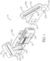
Fig. 1 is an exploded perspective view of a first embodiment of a webbing-buckling device of a multi-point seat belt system in accordance with the present invention, showing the webbing-buckling device is unlocked; -
Fig. 2 is another exploded perspective view of the webbing-buckling device inFig. 1 ; -
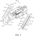
Fig. 3 is an enlarged and exploded perspective view of a buckle assembly of the webbing-buckling device inFig. 1 ; -
Fig. 4 is another enlarged and exploded perspective view of a tongue assembly of the webbing-buckling device inFig. 1 ; -
Fig. 5 is a front side view of the webbing-buckling device inFig. 1 , showing an outer shell is disposed around the buckle assembly, and a tongue shell is disposed around the tongue assembly; -
Fig. 6 is an operational perspective view of the webbing-buckling device inFig. 1 , showing the webbing-buckling device is applied to a four-point seat belt system on a seat of a vehicle; -
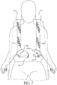
Fig. 7 is a front side view of the webbing-buckling device inFig. 6 , showing the webbing-buckling device is unlocked; -
Fig. 8 is a front side view of the webbing-buckling device inFig. 6 , showing the webbing-buckling device is locked; -
Fig. 9 is another operational perspective view of the webbing-buckling device inFig. 1 , showing the webbing-buckling device is applied to a six-point seat belt system on a seat of a vehicle; -
Fig. 10 is a front side view of the webbing-buckling device inFig. 9 , showing the webbing-buckling device is unlocked; -
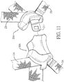
Fig. 11 is an enlarged perspective view of the webbing-buckling device inFig. 10 ; -
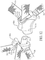
Fig. 12 is another perspective view of the webbing-buckling device inFig. 10 ; -
Fig. 13 is an enlarged side view in partial section of the webbing-buckling device inFig. 10 , showing a webbing is inserted through a first frame portion and a webbing-locking member, showing the webbing-buckling device is unlocked; -
Fig. 14 is an enlarged side view in partial section of the webbing-buckling device inFig. 10 , showing the webbing is fixed between the first frame portion and the webbing-locking member; -
Fig. 15 is another front side view of the webbing-buckling device inFig. 9 , showing the webbing-buckling device is locked; -
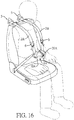
Fig. 16 is an operational perspective view of a four-point seat belt system without a retractor, showing the webbing-buckling device inFig. 1 is applied to the four-point seat belt system without the retractor; -
Fig. 17 is a front side view of the four-point seat belt system without the retractor inFig. 16 , showing the webbing-buckling device is unlocked; -
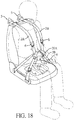
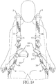
Fig. 18 is an operational perspective view of a six-point seat belt system without a retractor, showing the webbing-buckling device inFig. 1 is applied to the six-point seat belt system without the retractor; -
Fig. 19 is a front side view of the six-point seat belt system without the retractor inFig. 18 , showing the webbing-buckling device is unlocked; -
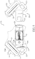
Fig. 20 is an exploded perspective view of a second embodiment of a webbing-buckling device of a multi-point seat belt system in accordance with the present invention, showing the webbing-buckling device is unlocked; -
Fig. 21 is another exploded perspective view of the webbing-buckling device inFig. 20 ; -
Fig. 22 is a front side view of the webbing-buckling device inFig. 20 , showing a tongue shell is disposed around a tongue assembly; -
Fig. 23 is an operational perspective view of the webbing-buckling device inFig. 20 , showing the webbing-buckling device is applied to a five-point seat belt system on a seat of a vehicle; -
Fig. 24 is a front side view of the webbing-buckling device inFig. 23 , showing the webbing-buckling device is unlocked; -
Fig. 25 is a front side view of the webbing-buckling device inFig. 23 , showing the webbing-buckling device is locked; -
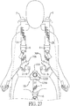
Fig. 26 is an operational perspective view of a five-point seat belt system without a retractor, showing the webbing-buckling device inFig. 20 is applied to the five-point seat belt system without the retractor; -
Fig. 27 is a front side view of the five-point seat belt system without the retractor inFig. 26 , showing the webbing-buckling device is unlocked; -
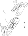
Fig. 28 is an exploded perspective view of a third embodiment of a webbing-buckling device of a multi-point seat belt system in accordance with the present invention, showing the webbing-buckling device is unlocked; -
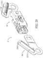
Fig. 29 is another exploded perspective view of the webbing-buckling device inFig. 28 ; -
Fig. 30 is an enlarged and exploded perspective view of the webbing-buckling device inFig. 28 ; -
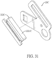
Fig. 31 is another enlarged and exploded perspective view of the webbing-buckling device inFig. 28 ; and -
Fig. 32 is an enlarged side view in partial section of the webbing-buckling device inFig. 31 , showing a webbing is inserted through a first frame portion and a webbing-locking member. - With reference to
Figs. 1 to 4 , a first embodiment of a webbing-bucklingdevice 1A in accordance with the present invention comprises abuckle assembly 10A and atongue assembly 20A. - With reference to
Figs. 1 to 3 , thebuckle assembly 10A has abuckle base 11, a lockingassembly 12, and a webbing-lockingmember 13. Thebuckle base 11 is made of a rigid material and has abody 111 and afirst frame portion 112. Thefirst frame portion 112 is formed on an end of thebody 111 and has a first throughhole 1121 and twofirst sides 1122. The first throughhole 1121 is formed through thefirst frame portion 112 and has two ends. The twofirst sides 1122 are formed on the two ends of the first throughhole 1121 respectively. - With reference to
Figs. 1 to 3 , and12 , the lockingassembly 12 is disposed on thebody 111 of thebuckle base 11 and has alocking mechanism 121, a pressingmember 122, and atongue slot 111A. Thelocking mechanism 121 is disposed on thebody 111 of thebuckle base 11. The pressingmember 122 is disposed on thelocking mechanism 121. Thetongue slot 111A is formed on an end of the lockingassembly 12 opposite to thefirst frame portion 112. The pressingmember 122 selectively drives thelocking mechanism 121 to change to an unlocked state. The lockingassembly 12 can be a known product. The lockingassembly 12 is not an improved part in the present invention. Detailed structure of the lockingassembly 12 will not be described herein. - With reference to
Figs. 1 to 3 , and13 , the webbing-lockingmember 13 is inserted through the first throughhole 1121 of thefirst frame portion 112 of thebuckle base 11. The webbing-lockingmember 13 is able to move relative to thefirst frame portion 112. The webbing-lockingmember 13 has a firstside plate portion 131, a secondside plate portion 132, and a throughportion 133. The firstside plate portion 131 and the secondside plate portion 132 are opposite to each other at a spaced interval. The firstside plate portion 131 and the secondside plate portion 132 have a height difference. The throughportion 133 is located between the firstside plate portion 131 and the secondside plate portion 132 and has a throughgroove 134 and twowalls 135. The throughgroove 134 is downwardly and inclinedly extends from the firstside plate portion 131 to the secondside plate portion 132 and has two side edges. The twowalls 135 are respectively located at the two side edges of the throughgroove 134 and are both connected to the firstside plate portion 131 and the secondside plate portion 132. Each one of the twowalls 135 has an outer surface and aslide groove 136. Theslide groove 136 is formed on the outer surface of each one of the twowalls 135, extends longitudinally, and is located between the firstside plate portion 131 and the secondside plate portion 132. The firstside plate portion 131 has a top edge and aflange 137. Theflange 137 is formed on and protrudes from the top edge of the firstside plate portion 131. - With reference to
Figs. 1 to 3 , and13 , in the webbing-lockingmember 13, the throughportion 133 is inserted through the first throughhole 1121 of thefirst frame portion 112. The firstside plate portion 131 and the secondside plate portion 132 are respectively located at two opposite sides of thefirst frame portion 112. The twofirst sides 1122 of thefirst frame portion 112 are respectively inserted into theslide grooves 136 of the twowalls 135 in the webbing-lockingmember 13. The throughportion 133 of the webbing-lockingmember 13 is limited by the first throughhole 1121 of thefirst frame portion 112. The webbing-lockingmember 13 is able to slide in thefirst frame portion 112. - With reference to
Figs. 1 to 4 , thetongue assembly 20A is detachably disposed on thebuckle assembly 10A and has atongue base 21 and a webbing-fixingmember 22. Thetongue base 21 is made of a rigid material and has atongue portion 211 and asecond frame portion 212. Thesecond frame portion 212 is formed on an end of thetongue portion 211 and has a second throughhole 2121 and twosecond sides 2122. The second throughhole 2121 is formed through thesecond frame portion 212 and has two ends. Thesecond sides 2122 are formed on the two ends of the second throughhole 2121 respectively. - With reference to
Figs. 1 to 4 ,13 , and14 , the webbing-fixingmember 22 is inserted through the second throughhole 2121 of thesecond frame portion 212 of thetongue base 21. The webbing-fixingmember 22 is able to move relative to thesecond frame portion 212. Structures of the webbing-fixingmember 22 and the webbing-lockingmember 13 are the same. - With reference to
Figs. 1 ,2 ,4 , and13 , the webbing-fixingmember 22 has a firstside plate portion 221, a secondside plate portion 222, and a throughportion 223. The firstside plate portion 221 and the secondside plate portion 222 are opposite to each other at a spaced interval. The firstside plate portion 221 and the secondside plate portion 222 have a height difference. The throughportion 223 is located between the firstside plate portion 221 and the secondside plate portion 222 and has a throughgroove 224 and twowalls 225. The throughgroove 224 downwardly and inclinedly extends from the firstside plate portion 221 to the secondside plate portion 222 and has two side edges. The twowalls 225 are respectively located at the two side edges of the throughgroove 224 and are both connected to the firstside plate portion 221 and the secondside plate portion 222. Each one of the twowalls 225 has an outer surface and aslide groove 226. Theslide groove 226 is formed on the outer surface of each one of the twowalls 225, extends longitudinally, and is located between the firstside plate portion 221 and the secondside plate portion 222. The firstside plate portion 221 has a top edge and aflange 227. Theflange 227 is formed on and protrudes from the top edge of the firstside plate portion 221. - With reference to
Figs. 1 to 4 ,13 , and14 , in the first embodiment, the throughportion 223 of the webbing-fixingmember 22 is inserted through the second throughhole 2121 of thesecond frame portion 212. The firstside plate portion 221 and the secondside plate portion 222 are respectively located at two opposite sides of thesecond frame portion 212. The twosecond sides 2122 of thesecond frame portion 212 are respectively inserted into theslide grooves 226 of the twowalls 225 in the webbing-fixingmember 22. The throughportion 223 of the webbing-fixingmember 22 is limited by the second throughhole 2121 of thesecond frame portion 212. The webbing-fixingmember 22 is able to slide in thesecond frame portion 212. - With reference to
Figs. 1 to 5 , in the first embodiment, thebuckle base 11 of thebuckle assembly 10A has a first connectingportion 113. The first connectingportion 113 is formed below thefirst frame portion 112 and has a first connectinghole 1131 formed through the first connectingportion 113. Thetongue base 21 of thetongue assembly 20A has a second connectingportion 213. The second connectingportion 213 is formed below thesecond frame portion 212 and has a second connectinghole 2131 formed through the second connectingportion 213. - With reference to
Fig. 5 , thebuckle assembly 10A has anouter shell 14. Theouter shell 14 covers thebody 111 of thebuckle base 11 and thelocking mechanism 121 of the lockingassembly 12. With reference toFig. 12 , thebuckle assembly 10A further has anothertongue slot 111A disposed on a side of thebuckle assembly 10A opposite to thefirst frame portion 112. Thetongue portion 211 of thetongue assembly 20A can be inserted into thetongue slot 111A. Thetongue assembly 20A has atongue shell 23. Thetongue shell 23 covers thetongue base 21. - With reference to
Figs. 6 and9 , the webbing-bucklingdevice 1A can be applied to a four-point seat belt system or a six-point seat belt system. With reference toFigs. 16 and18 , the webbing-bucklingdevice 1A can be applied to a four-point seat belt system without a retractor 4 or a six-point seat belt system without a retractor 4. - With reference to
Fig. 6 and9 , the webbing-bucklingdevice 1A can be applied to the four-point seat belt system or the six-point seat belt system having at least one retractor 4. The at least one retractor 4 can be one or two retractors. Each one of the at least one retractor 4 is disposed on a seat back of a seat in a vehicle, can retract a webbing automatically, and has an inclining locking mechanism disposed in each one of the at least one retractor 4. When the vehicle is inclined, thewebbing webbing - The multi-point seat belt system has one retractor 4 disposed below the seat back of the seat and connected to a Y-shaped webbing member. Two webbings 2A, 2B of the Y-shaped webbing member are respectively inserted through the
buckle assembly 10A and thetongue assembly 20A of the webbing-bucklingdevice 1A. Distal ends of the twowebbings Fig. 6 , the multi-point seat belt system has two retractors 4. The two retractors 4 are respectively disposed on the opposite top-back sides of the seat back and are respectively connected to twowebbings - With reference to
Figs. 6 and9 , the twowebbings buckle assembly 10A and thetongue assembly 20A of the webbing-bucklingdevice 1A. Distal ends of the twowebbings Fig. 9 , two auxiliary webbings having adjustingmembers 6 are respectively disposed on the opposite front sides of the cushion in the seat and are respectively connected to the first connectingportion 113 of thebuckle assembly 10A and the second connectingportion 213 of thetongue assembly 20A to form the six-point seat belt system having six fixing points. - With reference to
Figs. 6 to 12 , the twowebbings buckle assembly 10A and thetongue assembly 20A. An end of each one of the twowebbings webbings webbings member 13 and thefirst frame portion 112 and a relative position between the webbing-fixingmember 22 and thesecond frame portion 212 for respectively and uni-directionally locking the twowebbings device 1A on thewebbings auxiliary webbings members 6. The adjustingmembers 6 are known products. Detailed structure of each one of the adjustingmembers 6 will not be described herein. - With reference to
Figs. 6 to 12 ,13 , and14 , an occupant sits on the seat. When the occupant wants to adjust the height of the webbing-bucklingdevice 1A, two hands of the occupant intuitionally and respectively hold thebuckle base 11 of thebuckle assembly 10A and thetongue base 21 of thetongue assembly 20A. The webbing-lockingmember 13 is pressed downwardly. A relative motion is generated between thefirst frame portion 112 and the webbing-lockingmember 13 for unlocking one of thewebbings 2A. The webbing-fixingmember 22 is pressed downwardly. A relative motion is generated between thesecond frame portion 212 and the webbing-fixingmember 22 for unlocking the other one of thewebbings 2B. Simultaneously, thebuckle base 11 of thebuckle assembly 10A and thetongue base 21 of thetongue assembly 20A are upwardly pushed by the occupant. Thebuckle assembly 10A and thetongue assembly 20A are adjusted to suitable positions on thewebbings device 1A, tensions of the webbings 2A, 2B are respectively applied to thebuckle assembly 10A and thetongue assembly 20A. The webbing-lockingmember 13 is pushed upwardly. One of thewebbings 2A is re-locked by thefirst frame portion 112 and the webbing-lockingmember 13. The webbing-fixingmember 22 is pushed upwardly. The other one of thewebbings 2B is re-locked by thesecond frame portion 212 and the webbing-fixingmember 22. Thewebbings device 1A. - With reference to
Figs. 1 ,2 , and6 to 12 , the occupant sits on the seat in the vehicle. Thetongue portion 211 in thetongue assembly 20A is inserted into thebuckle assembly 10A and is locked by the lockingassembly 12. The webbing-bucklingdevice 1A is located in front of a torso of the occupant. When the six-point seat belt system is correctly locked, the inclining locking mechanism disposed in each one of the retractors 4 is locked, or the retractors 4 are locked due to emergency deceleration or brake, the relative position between the webbing-lockingmember 13 and thefirst frame portion 112 and the relative position between the webbing-fixingmember 22 and thesecond frame portion 212 are changed by the tensions of the webbings 2A, 2B for locking thewebbings webbings 2A is locked between the webbing-lockingmember 13 and thefirst frame portion 112. The other one of thewebbings 2B is locked between the webbing-fixingmember 22 and thesecond frame portion 212. Thewebbings webbings - When the webbing-buckling
device 1A can be applied to a four-point seat belt system without a retractor or a six-point seat belt system without a retractor, the assemblies in the four-point seat belt system without the retractor or the six-point seat belt system without the retractor are similar to the assemblies in the four-point seat belt system having the at least one retractor 4 or the six-point seat belt system having the at least one retractor 4. With reference toFigs. 16 to 19 , the difference is as follows. The twowebbings members 6 respectively. Ends of the twoweddings webbings members 6 to fit occupants with different builds. - The relative position between the webbing-locking
member 13 and thefirst frame portion 112 and the relative position between the webbing-fixingmember 22 and thesecond frame portion 212 are changed by the tensions of the webbings 2A, 2B for locking thewebbings webbings 2A is locked between the webbing-lockingmember 13 and thefirst frame portion 112. The other one of thewebbings 2B is locked between the webbing-fixingmember 22 and thesecond frame portion 212. Thewebbings webbings - With reference to
Figs. 20 to 22 , in a second embodiment of the present invention, the webbing-bucklingdevice 1B has abuckle assembly 10B and twotongue assemblies - With reference to
Figs. 20 to 22 , thebuckle assembly 10B has acentral shell 11B, twotongue slots 111B, a webbing-connectingportion 123B, and a lockingassembly 12B. Thecentral shell 11B has two opposite sides and a bottom. The twotongue slots 111B are respectively formed through the two opposite sides of thecentral shell 11B. The webbing-connectingportion 123B is disposed on the bottom of thecentral shell 11B. The lockingassembly 12B is disposed in thecentral shell 11B and has alocking mechanism 121B and apressing member 122B. Thelocking mechanism 121B is disposed in thecentral shell 11B. The pressingmember 122B is disposed on thelocking mechanism 121B. The pressingmember 122B selectively drives thelocking mechanism 121B to change to an unlocked state. The lockingassembly 12B can be a known product. The lockingassembly 12B is not an improved part in the present invention. Detailed structures of the lockingassembly 12B will not be described herein. - With reference to
Figs. 20 to 22 , structures of thetongue assemblies tongue assemblies tongue assemblies tongue base member tongue base tongue portion second frame portion second frame portion tongue portion hole second frame portion member hole second frame portion tongue base member second frame portion tongue assemblies webbings tongue portions tongue base tongue assemblies tongue slots 111B of thebuckle assembly 10B for locking or unlocking simultaneously. - With reference to
Figs. 20 to 22 , in each one of the twotongue assemblies tongue base portion portion second frame portion hole portion - With reference to
Fig. 22 , each one of the twotongue assemblies tongue shell tongue shell tongue base - The structures of the tongue bases 21, 21B, 31B in the first embodiment and the second embodiment are the same. The structures of the webbing-fixing
members members - With reference to
Figs. 23 to 25 , the webbing-bucklingdevice 1B can be applied to a five-point seat belt system having at least one retractor 4. Furthermore, the webbing-bucklingdevice 1B can be applied to a seven-point seat belt system having at least one retractor. With reference toFigs. 26 to 27 , the webbing-bucklingdevice 1B can be applied to a five-point seat belt system without a retractor. Furthermore, the webbing-buckling device can be applied to a seven-point seat belt system without a retractor. - With reference to
Figs. 23 to 25 , the webbing-bucklingdevice 1B can be applied to the five-point seat belt system having at least one retractor 4. The at least one retractor 4 can be one or two retractors. Each one of the at least one retractor 4 is disposed on a seat back of a seat in a vehicle, can retract a webbing automatically, and has an inclining locking mechanism disposed in each one of the at least one retractor 4. When the vehicle is inclined, thewebbing - With reference to
Figs. 23 to 25 , the at least one retractor 4 is one, is disposed below the seat back of the seat, and is connected to a Y-shaped webbing member. Two webbings 2A, 2B of the Y-shaped webbing member are respectively inserted through thebuckle assembly 10B and thetongue assemblies device 1B. Distal ends of the twowebbings webbings webbings tongue assemblies webbings portion 123B is connected to anauxiliary webbing 7 having an adjustingmember 6. Theauxiliary webbing 7 is connected to a front center of the seat to form a fixing point. In addition, two opposite front sides of the seat are respectively two auxiliary webbings having adjusting members. The two auxiliary webbings are respectively connected to the second connectingportions tongue assemblies - The second embodiment of the webbing-buckling
device 1B is applied to the multi-point seat belt system. Assemblies of the twotongue assemblies webbings tongue assembly 20A and thewebbings - When an occupant sits on the seat, the occupant may want to adjust the height of the webbing-buckling
device 1B. The height adjustments of the webbing-bucklingdevice - With reference to
Figs. 28 to 29 , in a third embodiment of a webbing-bucklingdevice 1C has abuckle assembly 10C and atongue assembly 20C. Thebuckle assemblies devices buckle assemblies side plate portions 132 in the first embodiment and the third embodiment. With reference toFigs. 13 and32 , atop surface area 1321C of the secondside plate portion 132C in the third embodiment is larger than a top surface area of the secondside plate portion 132 in the first embodiment for pressing easily. - With reference to
Figs. 30 and31 , thetongue assemblies 20C of the webbing-bucklingdevices side plate portions top surface area 2221C of the secondside plate portion 222C in the third embodiment is larger than a top surface area of the secondside plate portion 222 in the first embodiment for pressing easily. - When the webbing-buckling
device 1A is applied to the multi-point seat belt system on the seat of the vehicle, the webbing-bucklingdevice 1A is selectively connected to the twowebbings device 1A has onebuckle assembly 10A and onetongue assembly 20A, the webbing-lockingmember 13 is slidably inserted into thefirst frame portion 112 of thebuckle base 11. The webbing-fixingmember 22 is slidably inserted into thesecond frame portion 212 of thetongue base 21. One of the two webbings is inserted between thefirst frame portion 112 of thebuckle assembly 10A and the webbing-lockingmember 13. The other one of the two webbings is inserted between thesecond frame portion 212 of thetongue assembly 20A and the webbing-fixingmember 22. The onebuckle assembly 10A and the onetongue assembly 20A are connected between the twowebbings device 1B has onebuckle assembly 10B and twotongue assemblies members second frame portions tongue assemblies webbings tongue assemblies members buckle assembly 10B and the twotongue assemblies webbings device 1B is applied between the twowebbings - Furthermore, when the webbing-buckling
device 1A is combined by thebuckle assembly 10A and thetongue assembly 20A, the structure of the webbing-lockingmember 13 and the structure of the webbing-fixingmember 22 are simplified. The firstside plate portion 131 and the secondside plate portion 132 of the webbing-lockingportion 13 are respectively located at the two opposite sides of thefirst frame portion 112. The firstside plate portion 221 and the secondside plate portion 222 of the webbing-fixingmember 22 are respectively located at the two opposite sides of thesecond frame portion 212. The webbing-lockingmember 13 and the webbing-fixingportion 22 are inserted through and are able to slide in thefirst frame portion 112 in thebuckle assembly 10A and thesecond frame portion 212 in thetongue assembly 20A respectively. - Alternatively, the webbing-buckling
device 1B is combined by thebuckle assembly 10B and the twotongue assemblies members tongue assemblies side plate portion 221B and the secondside plate portion 222B of each one of the webbing-fixingmembers second frame portions members second frame portions
Claims (8)
- A webbing-buckling device of a multi-point seat belt system applied to connect to two webbings (2A, 2B) of the multi-point seat belt system, and characterized in that the webbing-buckling device comprises:a buckle assembly (10A) havinga buckle base (11) made of a rigid material and having a body (111) and a first frame portion (112), the first frame portion (112) formed on an end of the body (111) and having a first through hole (1121) formed through the first frame portion (112);a locking assembly (12) disposed on the body (111) of the buckle base (11) and having a locking mechanism (121), a pressing member (122), and a tongue slot (111A), the locking mechanism (121) disposed on the body (111) of the buckle base (11), the pressing member (122) disposed on the locking mechanism (121), and the tongue slot (111A) formed on an end of the locking assembly (12) opposite to the first frame portion (112), wherein the pressing member (122) selectively drives the locking mechanism (121) to change to an unlocked state; anda webbing-locking member (13) inserted through the first through hole (1121) of the first frame portion (112) of the buckle base (11), wherein the webbing-locking member (13) is able to move relative to the first frame portion (112) for locking one of the two webbings (2A, 2B); anda tongue assembly (20A, 20B, 30B) detachably disposed on the buckle assembly (10A, 10B) and havinga tongue base (21, 21B, 31B) made of a rigid material and having a tongue portion (211, 211B, 311B) and a second frame portion (212), the second frame portion (212) formed on an end of the tongue portion (211, 211B, 311B) and having a second through hole (2121) formed through the second frame portion (212); anda webbing-fixing member (22) inserted through the second through hole (2121) of the second frame portion (212) of the tongue base (21, 21B, 31B), wherein the webbing-fixing member (22) is able to move relative to the second frame portion (212) for locking the other one of the two webbings (2A. 2B), the tongue portion (211) of the tongue base (21) of the tongue assembly (20A) is selectively inserted into the tongue slot (111A) of the locking assembly (12) of the buckle assembly (10A) for locking.
- The webbing-buckling device of the multi-point seat belt system as claimed in claim 1, wherein
each one of the webbing-locking member (13) and the webbing-fixing member (22) hasa first side plate portion (131, 221);a second side plate portion (132, 222) being opposite to the first side plate portion (131, 221) at a spaced interval, wherein the first side plate portion (131, 221) and the second side plate portion (132, 222) have a height difference; anda through portion (133, 223) located between the first side plate portion (131, 221) and the second side plate portion (132, 222) and havingthe first frame portion (112) of the buckle base (11) has two first sides (1122) formed on two ends of the first through hole (1121) respectively, the through portion (133) of the webbing-locking member (13) is inserted through the first through hole (1121) of the first frame portion (112), the first side plate portion (131) and the second side plate portion (132) of the webbing-locking member (13) are respectively located at two opposite sides of the first frame portion (112), the two first sides (1122) of the first frame portion (112) are respectively inserted into the slide grooves (136) of the two walls in the webbing-locking member (13), the through portion (133) of the webbing-locking member (13) is limited by the first through hole (1121) of the first frame portion (112), and the webbing-locking member (13) is able to slide in the first frame portion (112); anda through groove (134, 224) downwardly and inclinedly extending from the first side plate portion (131, 221) to the second side plate portion (132, 222) and having two side edges; andtwo walls (135,225) respectively located at the two side edges of the through groove (134, 224) and both connected to the first side plate portion (131, 221) and the second side plate portion (132, 222), wherein each one of the two walls (135,225) has an outer surface and a slide groove (136, 226) formed on the outer surface, extending longitudinally, and located between the first side plate portion (131, 221) and the second side plate portion (132, 222), the first side plate portion (131, 221) has a top edge and a flange (137, 227), and the flange (137, 227) is formed on and protrudes from the top edge of the first side plate portion (131, 221);
the second frame portion (212) of the tongue base (21) has two second sides (2122) formed on two ends of the second through hole (2121) respectively, the through portion (223) of the webbing-fixing member (22) is inserted through the second through hole (2121) of the second frame portion (212), the first side plate portion (221) and the second side plate portion (222) of the webbing-fixing member (22) are respectively located at two opposite sides of the second frame portion (222), the two second sides (2122) of the second frame portion (212) are respectively inserted into the slide grooves (226) of the two walls (225) in the webbing-fixing member (22), the through portion (133) of the webbing-fixing member (22) is limited by the second through hole (2121) of the second frame portion (212), and the webbing-fixing member (22) is able to slide in the second frame portion (212). - The webbing-buckling device of the multi-point seat belt system as claimed in claim 2, wherein
the buckle assembly (10A) has an outer shell (14), and the outer shell (14) of the buckle assembly (10A) covers the body (111) of the buckle base (11) and the locking mechanism (121) of the locking assembly (12); and
the tongue assembly (20A) has a tongue shell (23), and the tongue shell (23) of the tongue assembly (20A) covers the tongue base (21, 21B, 31B). - The webbing-buckling device of the multi-point seat belt system as claimed in any one of claims 1 to 3, wherein
the buckle base (11) of the buckle assembly (10A) has a first connecting portion (113), and the first connecting portion (113) is formed below the first frame portion (112) and has a first connecting hole (1131) formed through the first connecting portion (113); and
the tongue base (21, 21B, 31B) of the tongue assembly (20A, 20B, 30B) has a second connecting portion (213), and the second connecting portion (213) is formed below the second frame portion (212) and has a second connecting hole (2131) formed through the second connecting portion (213). - A webbing-buckling device of a multi-point seat belt system applied to connect to two webbings (2A, 2B) of the multi-point seat belt system, the webbing-buckling device comprising:a buckle assembly (10B) having a central shell (11B), two tongue slots (111B), a webbing-connecting portion (123B), and a locking assembly (12, 12B), the central shell (11B) having two opposite sides and a bottom, the two tongue slots (111B) respectively formed through the two opposite sides of the central shell (11B), the webbing-connecting portion (123B) disposed on the bottom of the central shell (11B), and the locking assembly (12B) disposed in the central shell (11B) and having a locking mechanism (121B) and a pressing member (122B), the locking mechanism (121B) disposed in the central shell (11B), and the pressing member (122B) disposed on the locking mechanism (121B), wherein the pressing member (122B) selectively drives the locking mechanism (121B) to change to an unlocked state; andtwo tongue assemblies (20B, 30B) detachably disposed on the buckle assembly (10B), and each one of the two tongue assemblies (20B, 30B) havinga tongue base (21B, 31B) made of a rigid material and having a tongue portion (211B, 311B) and a second frame portion (212B, 312B), the second frame portion (212B, 312B) formed on an end of the tongue portion (211, 211B, 311B) and having a second through hole (2121B, 3121B) formed through the second frame portion (212B, 312B); anda webbing-fixing member (22B, 32B) inserted through the second through hole (2121B, 3121B) of the second frame portion (212B, 312B) of the tongue base (21B, 31B), wherein the webbing-fixing member (22B, 32B) is able to move relative to the second frame portion (212B, 312B); andwherein the two tongue assemblies (20B, 30B) are able to lock the two webbings (2A, 2B) respectively, the tongue portion (211, 211B, 311B)s of the tongue base (21, 21B, 31B)s of the two tongue assemblies (20B, 30B) are respectively and selectively inserted into the tongue slots (111B) of the buckle assembly (10B) for locking simultaneously.
- The webbing-buckling device of the multi-point seat belt system as claimed in claim 5, wherein
each one of the webbing-fixing members (22B, 32B) of the two tongue assemblies (20B, 30B) hasa first side plate portion (221);a second side plate portion (222) being opposite to each other at a spaced interval, wherein the first side plate portion (221) and the second side plate portion (222) have a height difference;a through portion (223) located between the first side plate portion (221) and the second side plate portion (222) and havingin each one of the two tongue assemblies (20B, 30B), the second frame portion (212B, 312B) of the tongue base (21B, 31B) has two second sides formed on two ends of the second through hole (2121B, 3121B) respectively, the through portion (223) of the webbing-fixing member (22B, 32B) is inserted through the second through hole (2121B, 3121B) of the second frame portion (212B, 312B), the first side plate portion (131) and the second side plate portion (222) of the webbing-fixing member (22B, 32B) are respectively located at two opposite sides of the second frame portion (212B, 312B), the two second sides of the second frame portion (212B, 312B) are respectively inserted into the slide grooves (226) of the two walls (225) in the webbing-fixing member (22B, 32B), the through portion (223) of the webbing-fixing member (22B, 32B) is limited by the second through hole (2121B, 3121B) of the second frame portion (212B, 312B), and the webbing-fixing member (22B, 32B) is able to slide in the second frame portion (212B, 312B).a through groove (224) downwardly and inclinedly extending from the first side plate portion (221) to the second side plate portion (222) and having two side edges; andtwo walls (225) respectively located at the two side edges of the through groove (224) and both connected to the first side plate portion (221) and the second side plate portion (222), wherein each one of the two walls (225) has an outer surface and a slide groove (226) formed on the outer surface, extending longitudinally, and located between the first side plate portion (221) and the second side plate portion (222), the first side plate portion (221) has a top edge and a flange (227), and the flange (227) is formed on and protrudes from the top edge of the first side plate portion (221); - The webbing-buckling device of the multi-point seat belt system as claimed in claim 6, wherein each one of the tongue assemblies (20B, 30B) has a tongue shell (23B, 33B), and the tongue shell (23B, 33B) covers the tongue base (21B, 31B).
- The webbing-buckling device of the multi-point seat belt system as claimed in any one of claims 5 to 7, wherein in each one of the two tongue assemblies (20B, 30B), the tongue base (21B, 31B) has a second connecting portion (213B, 313B), and the second connecting portion (213B, 313B) is formed below the second frame portion (212B, 312B) and has a second connecting hole (2131B, 3131B) formed through the second connecting portion (213B, 313B).
Applications Claiming Priority (1)
| Application Number | Priority Date | Filing Date | Title |
|---|---|---|---|
| TW107131139A TWI673020B (en) | 2018-09-05 | 2018-09-05 | Ribbon fastening device for multi-point seat belt system |
Publications (3)
| Publication Number | Publication Date |
|---|---|
| EP3620076A1 true EP3620076A1 (en) | 2020-03-11 |
| EP3620076C0 EP3620076C0 (en) | 2024-01-10 |
| EP3620076B1 EP3620076B1 (en) | 2024-01-10 |
Family
ID=67514477
Family Applications (1)
| Application Number | Title | Priority Date | Filing Date |
|---|---|---|---|
| EP19189542.4A Active EP3620076B1 (en) | 2018-09-05 | 2019-08-01 | Webbing-buckling device of a multi-point seat belt system |
Country Status (5)
| Country | Link |
|---|---|
| US (1) | US11007973B2 (en) |
| EP (1) | EP3620076B1 (en) |
| JP (1) | JP6989146B2 (en) |
| CN (1) | CN110877595A (en) |
| TW (1) | TWI673020B (en) |
Cited By (1)
| Publication number | Priority date | Publication date | Assignee | Title |
|---|---|---|---|---|
| EP3919328A1 (en) * | 2020-06-03 | 2021-12-08 | Hornling Industrial Inc. | Latching mechanism |
Families Citing this family (4)
| Publication number | Priority date | Publication date | Assignee | Title |
|---|---|---|---|---|
| US20230036452A1 (en) * | 2021-07-28 | 2023-02-02 | Safe, Inc. | Dual three-point restraint system |
| USD1076713S1 (en) * | 2023-09-27 | 2025-05-27 | Wen-yuan Wu | Seat belt locking buckle |
| USD1076714S1 (en) * | 2023-09-27 | 2025-05-27 | Wen-yuan Wu | Seat belt locking buckle |
| USD1113068S1 (en) * | 2024-02-24 | 2026-02-10 | Taiwan Racing Products Co., Ltd. | Seat belt lift latch |
Citations (3)
| Publication number | Priority date | Publication date | Assignee | Title |
|---|---|---|---|---|
| DE10109868A1 (en) * | 2000-03-03 | 2001-09-27 | Trw Vehicle Safety Systems | Seat belt arrangement for motor vehicle has shoulder straps connected to vehicle and extending from upper section of seat close to shoulders of occupant, and lap straps extending from sides of seat and partially over hips of occupant |
| US20070044285A1 (en) * | 2005-08-02 | 2007-03-01 | Ryoji Kawamura | Belt lock |
| US20150272281A1 (en) * | 2014-03-28 | 2015-10-01 | Wonderland Nurserygoods Company Limited | Buckle device |
Family Cites Families (15)
| Publication number | Priority date | Publication date | Assignee | Title |
|---|---|---|---|---|
| JP2004136768A (en) * | 2002-10-17 | 2004-05-13 | Takata Corp | Seat belt device |
| US6837547B2 (en) * | 2003-04-21 | 2005-01-04 | Trw Vehicle Safety Systems Inc. | Vehicle occupant protection device including an end release buckle assembly |
| US9480308B2 (en) * | 2007-10-12 | 2016-11-01 | Ford Global Technologies, Llc | Buckle-tongue arrangement for four point seat belt system |
| KR100947497B1 (en) * | 2009-10-13 | 2010-03-17 | 남 영 박 | A automobile safety belt |
| US8402617B2 (en) * | 2011-03-16 | 2013-03-26 | Liang-Hsiung Wang | Sand-removing seat belt buckle |
| WO2013188614A1 (en) | 2012-06-13 | 2013-12-19 | Indiana Mills & Manufacturing Inc | Integral multi-point restraint system for vehicle seat |
| KR101552659B1 (en) * | 2012-08-10 | 2015-09-14 | 아우토리브 디벨롭먼트 아베 | Buckle apparatus for seat belt |
| US10065596B2 (en) * | 2015-03-17 | 2018-09-04 | Halcore Group, Inc. | Vehicle safety belt |
| US10137855B2 (en) * | 2015-05-19 | 2018-11-27 | Key Safety Systems, Inc. | Safety belt system with signal sending tension sensor |
| US9781977B2 (en) * | 2015-08-11 | 2017-10-10 | Shield Restraint Systems, Inc. | Interlocking web connectors for occupant restraint systems and associated methods of use and manufacture |
| KR101623438B1 (en) * | 2016-01-19 | 2016-05-23 | 김대길 | Portable apparatus for fixing safety seat belt for vehicles |
| TWI617467B (en) | 2016-08-16 | 2018-03-11 | Wang liang xiong | Belt webbing adjustment device |
| TWI636906B (en) * | 2017-08-31 | 2018-10-01 | 王亮雄 | Multi-point safety belt device |
| CN108437927A (en) * | 2018-04-17 | 2018-08-24 | 安徽车鑫保汽车销售有限公司 | Automatic dismounting device of car blet |
| TWI698362B (en) * | 2019-03-11 | 2020-07-11 | 王亮雄 | Multi-point seat belt system |
-
2018
- 2018-09-05 TW TW107131139A patent/TWI673020B/en active
- 2018-09-13 CN CN201811066725.5A patent/CN110877595A/en active Pending
-
2019
- 2019-08-01 EP EP19189542.4A patent/EP3620076B1/en active Active
- 2019-08-06 US US16/532,851 patent/US11007973B2/en active Active
- 2019-08-20 JP JP2019150746A patent/JP6989146B2/en active Active
Patent Citations (3)
| Publication number | Priority date | Publication date | Assignee | Title |
|---|---|---|---|---|
| DE10109868A1 (en) * | 2000-03-03 | 2001-09-27 | Trw Vehicle Safety Systems | Seat belt arrangement for motor vehicle has shoulder straps connected to vehicle and extending from upper section of seat close to shoulders of occupant, and lap straps extending from sides of seat and partially over hips of occupant |
| US20070044285A1 (en) * | 2005-08-02 | 2007-03-01 | Ryoji Kawamura | Belt lock |
| US20150272281A1 (en) * | 2014-03-28 | 2015-10-01 | Wonderland Nurserygoods Company Limited | Buckle device |
Cited By (2)
| Publication number | Priority date | Publication date | Assignee | Title |
|---|---|---|---|---|
| EP3919328A1 (en) * | 2020-06-03 | 2021-12-08 | Hornling Industrial Inc. | Latching mechanism |
| US11571047B2 (en) | 2020-06-03 | 2023-02-07 | Hornling Industrial Inc. | Latching mechanism |
Also Published As
| Publication number | Publication date |
|---|---|
| JP2020037398A (en) | 2020-03-12 |
| JP6989146B2 (en) | 2022-01-05 |
| TW202010428A (en) | 2020-03-16 |
| US20200070770A1 (en) | 2020-03-05 |
| US11007973B2 (en) | 2021-05-18 |
| TWI673020B (en) | 2019-10-01 |
| EP3620076C0 (en) | 2024-01-10 |
| EP3620076B1 (en) | 2024-01-10 |
| CN110877595A (en) | 2020-03-13 |
Similar Documents
| Publication | Publication Date | Title |
|---|---|---|
| EP3620076B1 (en) | Webbing-buckling device of a multi-point seat belt system | |
| US20190061680A1 (en) | Multi-point seat belt assembly | |
| US6312015B1 (en) | Clamp for retractor belt | |
| US5176402A (en) | Detachable vehicle belt guide | |
| JP6368010B2 (en) | Webbing adjuster for seat belt system | |
| EP3486126B1 (en) | Webbing adjustment device | |
| US9022483B2 (en) | Seatbelt buckle tongue assembly | |
| US4848794A (en) | Free running cinching connector | |
| EP0693394A2 (en) | A child seat for a vehicle and a seat belt system for the child seat | |
| US10512309B2 (en) | Seat belt connector tongue assembly having locking mechanism | |
| JP2020011718A (en) | Webbing height adjustment device | |
| JP2003524549A (en) | Seat belt system | |
| US4878272A (en) | Tongue assembly | |
| CN102985298B (en) | Seatbelt fastening device and possess its seat safety belt apparatus | |
| EP0104621B1 (en) | Adjustable anchor mounting device | |
| EP3715187A1 (en) | Multi-point seat belt system | |
| US20110140405A1 (en) | Devices for adjusting tension in seat belts and other restraint system webs, and associated methods | |
| JP2760178B2 (en) | Vehicle seat belt device | |
| US7325879B2 (en) | Seat belt guide | |
| TW202504786A (en) | Protection reinforcement device for multi-point seat belt system of transportation vehicles | |
| JPH051629U (en) | Seat belt holder | |
| TW202519427A (en) | Webbing height adjuster and webbing height adjusting device | |
| CN111717153A (en) | Multi-point seat belt system | |
| JPH0228126Y2 (en) | ||
| JPS62241750A (en) | Seat belt device for automobile |
Legal Events
| Date | Code | Title | Description |
|---|---|---|---|
| PUAI | Public reference made under article 153(3) epc to a published international application that has entered the european phase |
Free format text: ORIGINAL CODE: 0009012 |
|
| STAA | Information on the status of an ep patent application or granted ep patent |
Free format text: STATUS: THE APPLICATION HAS BEEN PUBLISHED |
|
| AK | Designated contracting states |
Kind code of ref document: A1 Designated state(s): AL AT BE BG CH CY CZ DE DK EE ES FI FR GB GR HR HU IE IS IT LI LT LU LV MC MK MT NL NO PL PT RO RS SE SI SK SM TR |
|
| AX | Request for extension of the european patent |
Extension state: BA ME |
|
| STAA | Information on the status of an ep patent application or granted ep patent |
Free format text: STATUS: REQUEST FOR EXAMINATION WAS MADE |
|
| 17P | Request for examination filed |
Effective date: 20200615 |
|
| RBV | Designated contracting states (corrected) |
Designated state(s): AL AT BE BG CH CY CZ DE DK EE ES FI FR GB GR HR HU IE IS IT LI LT LU LV MC MK MT NL NO PL PT RO RS SE SI SK SM TR |
|
| STAA | Information on the status of an ep patent application or granted ep patent |
Free format text: STATUS: EXAMINATION IS IN PROGRESS |
|
| 17Q | First examination report despatched |
Effective date: 20220824 |
|
| GRAP | Despatch of communication of intention to grant a patent |
Free format text: ORIGINAL CODE: EPIDOSNIGR1 |
|
| STAA | Information on the status of an ep patent application or granted ep patent |
Free format text: STATUS: GRANT OF PATENT IS INTENDED |
|
| INTG | Intention to grant announced |
Effective date: 20230816 |
|
| GRAS | Grant fee paid |
Free format text: ORIGINAL CODE: EPIDOSNIGR3 |
|
| GRAA | (expected) grant |
Free format text: ORIGINAL CODE: 0009210 |
|
| STAA | Information on the status of an ep patent application or granted ep patent |
Free format text: STATUS: THE PATENT HAS BEEN GRANTED |
|
| AK | Designated contracting states |
Kind code of ref document: B1 Designated state(s): AL AT BE BG CH CY CZ DE DK EE ES FI FR GB GR HR HU IE IS IT LI LT LU LV MC MK MT NL NO PL PT RO RS SE SI SK SM TR |
|
| REG | Reference to a national code |
Ref country code: GB Ref legal event code: FG4D |
|
| REG | Reference to a national code |
Ref country code: CH Ref legal event code: EP |
|
| REG | Reference to a national code |
Ref country code: DE Ref legal event code: R096 Ref document number: 602019044773 Country of ref document: DE |
|
| REG | Reference to a national code |
Ref country code: IE Ref legal event code: FG4D |
|
| U01 | Request for unitary effect filed |
Effective date: 20240110 |
|
| U07 | Unitary effect registered |
Designated state(s): AT BE BG DE DK EE FI FR IT LT LU LV MT NL PT SE SI Effective date: 20240115 |
|
| PG25 | Lapsed in a contracting state [announced via postgrant information from national office to epo] |
Ref country code: IS Free format text: LAPSE BECAUSE OF FAILURE TO SUBMIT A TRANSLATION OF THE DESCRIPTION OR TO PAY THE FEE WITHIN THE PRESCRIBED TIME-LIMIT Effective date: 20240510 |
|
| PGFP | Annual fee paid to national office [announced via postgrant information from national office to epo] |
Ref country code: GB Payment date: 20240605 Year of fee payment: 6 |
|
| PG25 | Lapsed in a contracting state [announced via postgrant information from national office to epo] |
Ref country code: GR Free format text: LAPSE BECAUSE OF FAILURE TO SUBMIT A TRANSLATION OF THE DESCRIPTION OR TO PAY THE FEE WITHIN THE PRESCRIBED TIME-LIMIT Effective date: 20240411 |
|
| PG25 | Lapsed in a contracting state [announced via postgrant information from national office to epo] |
Ref country code: HR Free format text: LAPSE BECAUSE OF FAILURE TO SUBMIT A TRANSLATION OF THE DESCRIPTION OR TO PAY THE FEE WITHIN THE PRESCRIBED TIME-LIMIT Effective date: 20240110 Ref country code: RS Free format text: LAPSE BECAUSE OF FAILURE TO SUBMIT A TRANSLATION OF THE DESCRIPTION OR TO PAY THE FEE WITHIN THE PRESCRIBED TIME-LIMIT Effective date: 20240410 |
|
| PG25 | Lapsed in a contracting state [announced via postgrant information from national office to epo] |
Ref country code: ES Free format text: LAPSE BECAUSE OF FAILURE TO SUBMIT A TRANSLATION OF THE DESCRIPTION OR TO PAY THE FEE WITHIN THE PRESCRIBED TIME-LIMIT Effective date: 20240110 |
|
| PG25 | Lapsed in a contracting state [announced via postgrant information from national office to epo] |
Ref country code: RS Free format text: LAPSE BECAUSE OF FAILURE TO SUBMIT A TRANSLATION OF THE DESCRIPTION OR TO PAY THE FEE WITHIN THE PRESCRIBED TIME-LIMIT Effective date: 20240410 Ref country code: NO Free format text: LAPSE BECAUSE OF FAILURE TO SUBMIT A TRANSLATION OF THE DESCRIPTION OR TO PAY THE FEE WITHIN THE PRESCRIBED TIME-LIMIT Effective date: 20240410 Ref country code: IS Free format text: LAPSE BECAUSE OF FAILURE TO SUBMIT A TRANSLATION OF THE DESCRIPTION OR TO PAY THE FEE WITHIN THE PRESCRIBED TIME-LIMIT Effective date: 20240510 Ref country code: HR Free format text: LAPSE BECAUSE OF FAILURE TO SUBMIT A TRANSLATION OF THE DESCRIPTION OR TO PAY THE FEE WITHIN THE PRESCRIBED TIME-LIMIT Effective date: 20240110 Ref country code: GR Free format text: LAPSE BECAUSE OF FAILURE TO SUBMIT A TRANSLATION OF THE DESCRIPTION OR TO PAY THE FEE WITHIN THE PRESCRIBED TIME-LIMIT Effective date: 20240411 Ref country code: ES Free format text: LAPSE BECAUSE OF FAILURE TO SUBMIT A TRANSLATION OF THE DESCRIPTION OR TO PAY THE FEE WITHIN THE PRESCRIBED TIME-LIMIT Effective date: 20240110 |
|
| PG25 | Lapsed in a contracting state [announced via postgrant information from national office to epo] |
Ref country code: PL Free format text: LAPSE BECAUSE OF FAILURE TO SUBMIT A TRANSLATION OF THE DESCRIPTION OR TO PAY THE FEE WITHIN THE PRESCRIBED TIME-LIMIT Effective date: 20240110 |
|
| PG25 | Lapsed in a contracting state [announced via postgrant information from national office to epo] |
Ref country code: PL Free format text: LAPSE BECAUSE OF FAILURE TO SUBMIT A TRANSLATION OF THE DESCRIPTION OR TO PAY THE FEE WITHIN THE PRESCRIBED TIME-LIMIT Effective date: 20240110 |
|
| U20 | Renewal fee for the european patent with unitary effect paid |
Year of fee payment: 6 Effective date: 20240828 |
|
| REG | Reference to a national code |
Ref country code: DE Ref legal event code: R097 Ref document number: 602019044773 Country of ref document: DE |
|
| PG25 | Lapsed in a contracting state [announced via postgrant information from national office to epo] |
Ref country code: SM Free format text: LAPSE BECAUSE OF FAILURE TO SUBMIT A TRANSLATION OF THE DESCRIPTION OR TO PAY THE FEE WITHIN THE PRESCRIBED TIME-LIMIT Effective date: 20240110 |
|
| PG25 | Lapsed in a contracting state [announced via postgrant information from national office to epo] |
Ref country code: CZ Free format text: LAPSE BECAUSE OF FAILURE TO SUBMIT A TRANSLATION OF THE DESCRIPTION OR TO PAY THE FEE WITHIN THE PRESCRIBED TIME-LIMIT Effective date: 20240110 |
|
| PG25 | Lapsed in a contracting state [announced via postgrant information from national office to epo] |
Ref country code: SK Free format text: LAPSE BECAUSE OF FAILURE TO SUBMIT A TRANSLATION OF THE DESCRIPTION OR TO PAY THE FEE WITHIN THE PRESCRIBED TIME-LIMIT Effective date: 20240110 |
|
| PG25 | Lapsed in a contracting state [announced via postgrant information from national office to epo] |
Ref country code: SM Free format text: LAPSE BECAUSE OF FAILURE TO SUBMIT A TRANSLATION OF THE DESCRIPTION OR TO PAY THE FEE WITHIN THE PRESCRIBED TIME-LIMIT Effective date: 20240110 Ref country code: SK Free format text: LAPSE BECAUSE OF FAILURE TO SUBMIT A TRANSLATION OF THE DESCRIPTION OR TO PAY THE FEE WITHIN THE PRESCRIBED TIME-LIMIT Effective date: 20240110 Ref country code: RO Free format text: LAPSE BECAUSE OF FAILURE TO SUBMIT A TRANSLATION OF THE DESCRIPTION OR TO PAY THE FEE WITHIN THE PRESCRIBED TIME-LIMIT Effective date: 20240110 Ref country code: CZ Free format text: LAPSE BECAUSE OF FAILURE TO SUBMIT A TRANSLATION OF THE DESCRIPTION OR TO PAY THE FEE WITHIN THE PRESCRIBED TIME-LIMIT Effective date: 20240110 |
|
| PLBE | No opposition filed within time limit |
Free format text: ORIGINAL CODE: 0009261 |
|
| STAA | Information on the status of an ep patent application or granted ep patent |
Free format text: STATUS: NO OPPOSITION FILED WITHIN TIME LIMIT |
|
| 26N | No opposition filed |
Effective date: 20241011 |
|
| REG | Reference to a national code |
Ref country code: CH Ref legal event code: PL |
|
| PG25 | Lapsed in a contracting state [announced via postgrant information from national office to epo] |
Ref country code: MC Free format text: LAPSE BECAUSE OF FAILURE TO SUBMIT A TRANSLATION OF THE DESCRIPTION OR TO PAY THE FEE WITHIN THE PRESCRIBED TIME-LIMIT Effective date: 20240110 Ref country code: CH Free format text: LAPSE BECAUSE OF NON-PAYMENT OF DUE FEES Effective date: 20240831 |
|
| PG25 | Lapsed in a contracting state [announced via postgrant information from national office to epo] |
Ref country code: IE Free format text: LAPSE BECAUSE OF NON-PAYMENT OF DUE FEES Effective date: 20240801 |
|
| U20 | Renewal fee for the european patent with unitary effect paid |
Year of fee payment: 7 Effective date: 20250826 |
|
| PG25 | Lapsed in a contracting state [announced via postgrant information from national office to epo] |
Ref country code: CY Free format text: LAPSE BECAUSE OF FAILURE TO SUBMIT A TRANSLATION OF THE DESCRIPTION OR TO PAY THE FEE WITHIN THE PRESCRIBED TIME-LIMIT; INVALID AB INITIO Effective date: 20190801 |
|
| PG25 | Lapsed in a contracting state [announced via postgrant information from national office to epo] |
Ref country code: HU Free format text: LAPSE BECAUSE OF FAILURE TO SUBMIT A TRANSLATION OF THE DESCRIPTION OR TO PAY THE FEE WITHIN THE PRESCRIBED TIME-LIMIT; INVALID AB INITIO Effective date: 20190801 |