EP3619729B1 - Keypad device with rocker button mechanism - Google Patents
Keypad device with rocker button mechanism Download PDFInfo
- Publication number
- EP3619729B1 EP3619729B1 EP18743341.2A EP18743341A EP3619729B1 EP 3619729 B1 EP3619729 B1 EP 3619729B1 EP 18743341 A EP18743341 A EP 18743341A EP 3619729 B1 EP3619729 B1 EP 3619729B1
- Authority
- EP
- European Patent Office
- Prior art keywords
- faceplate
- circuit board
- keypad device
- switch
- plungers
- Prior art date
- Legal status (The legal status is an assumption and is not a legal conclusion. Google has not performed a legal analysis and makes no representation as to the accuracy of the status listed.)
- Active
Links
Images



Classifications
-
- H—ELECTRICITY
- H01—ELECTRIC ELEMENTS
- H01H—ELECTRIC SWITCHES; RELAYS; SELECTORS; EMERGENCY PROTECTIVE DEVICES
- H01H13/00—Switches having rectilinearly-movable operating part or parts adapted for pushing or pulling in one direction only, e.g. push-button switch
- H01H13/70—Switches having rectilinearly-movable operating part or parts adapted for pushing or pulling in one direction only, e.g. push-button switch having a plurality of operating members associated with different sets of contacts, e.g. keyboard
-
- H—ELECTRICITY
- H01—ELECTRIC ELEMENTS
- H01H—ELECTRIC SWITCHES; RELAYS; SELECTORS; EMERGENCY PROTECTIVE DEVICES
- H01H13/00—Switches having rectilinearly-movable operating part or parts adapted for pushing or pulling in one direction only, e.g. push-button switch
- H01H13/70—Switches having rectilinearly-movable operating part or parts adapted for pushing or pulling in one direction only, e.g. push-button switch having a plurality of operating members associated with different sets of contacts, e.g. keyboard
- H01H13/702—Switches having rectilinearly-movable operating part or parts adapted for pushing or pulling in one direction only, e.g. push-button switch having a plurality of operating members associated with different sets of contacts, e.g. keyboard with contacts carried by or formed from layers in a multilayer structure, e.g. membrane switches
- H01H13/705—Switches having rectilinearly-movable operating part or parts adapted for pushing or pulling in one direction only, e.g. push-button switch having a plurality of operating members associated with different sets of contacts, e.g. keyboard with contacts carried by or formed from layers in a multilayer structure, e.g. membrane switches characterised by construction, mounting or arrangement of operating parts, e.g. push-buttons or keys
- H01H13/7065—Switches having rectilinearly-movable operating part or parts adapted for pushing or pulling in one direction only, e.g. push-button switch having a plurality of operating members associated with different sets of contacts, e.g. keyboard with contacts carried by or formed from layers in a multilayer structure, e.g. membrane switches characterised by construction, mounting or arrangement of operating parts, e.g. push-buttons or keys characterised by the mechanism between keys and layered keyboards
-
- H—ELECTRICITY
- H01—ELECTRIC ELEMENTS
- H01H—ELECTRIC SWITCHES; RELAYS; SELECTORS; EMERGENCY PROTECTIVE DEVICES
- H01H13/00—Switches having rectilinearly-movable operating part or parts adapted for pushing or pulling in one direction only, e.g. push-button switch
- H01H13/70—Switches having rectilinearly-movable operating part or parts adapted for pushing or pulling in one direction only, e.g. push-button switch having a plurality of operating members associated with different sets of contacts, e.g. keyboard
- H01H13/78—Switches having rectilinearly-movable operating part or parts adapted for pushing or pulling in one direction only, e.g. push-button switch having a plurality of operating members associated with different sets of contacts, e.g. keyboard characterised by the contacts or the contact sites
- H01H13/807—Switches having rectilinearly-movable operating part or parts adapted for pushing or pulling in one direction only, e.g. push-button switch having a plurality of operating members associated with different sets of contacts, e.g. keyboard characterised by the contacts or the contact sites characterised by the spatial arrangement of the contact sites, e.g. superimposed sites
-
- H—ELECTRICITY
- H01—ELECTRIC ELEMENTS
- H01H—ELECTRIC SWITCHES; RELAYS; SELECTORS; EMERGENCY PROTECTIVE DEVICES
- H01H13/00—Switches having rectilinearly-movable operating part or parts adapted for pushing or pulling in one direction only, e.g. push-button switch
- H01H13/70—Switches having rectilinearly-movable operating part or parts adapted for pushing or pulling in one direction only, e.g. push-button switch having a plurality of operating members associated with different sets of contacts, e.g. keyboard
- H01H13/702—Switches having rectilinearly-movable operating part or parts adapted for pushing or pulling in one direction only, e.g. push-button switch having a plurality of operating members associated with different sets of contacts, e.g. keyboard with contacts carried by or formed from layers in a multilayer structure, e.g. membrane switches
- H01H13/705—Switches having rectilinearly-movable operating part or parts adapted for pushing or pulling in one direction only, e.g. push-button switch having a plurality of operating members associated with different sets of contacts, e.g. keyboard with contacts carried by or formed from layers in a multilayer structure, e.g. membrane switches characterised by construction, mounting or arrangement of operating parts, e.g. push-buttons or keys
- H01H13/7065—Switches having rectilinearly-movable operating part or parts adapted for pushing or pulling in one direction only, e.g. push-button switch having a plurality of operating members associated with different sets of contacts, e.g. keyboard with contacts carried by or formed from layers in a multilayer structure, e.g. membrane switches characterised by construction, mounting or arrangement of operating parts, e.g. push-buttons or keys characterised by the mechanism between keys and layered keyboards
- H01H13/7073—Switches having rectilinearly-movable operating part or parts adapted for pushing or pulling in one direction only, e.g. push-button switch having a plurality of operating members associated with different sets of contacts, e.g. keyboard with contacts carried by or formed from layers in a multilayer structure, e.g. membrane switches characterised by construction, mounting or arrangement of operating parts, e.g. push-buttons or keys characterised by the mechanism between keys and layered keyboards characterised by springs, e.g. Euler springs
-
- H—ELECTRICITY
- H01—ELECTRIC ELEMENTS
- H01H—ELECTRIC SWITCHES; RELAYS; SELECTORS; EMERGENCY PROTECTIVE DEVICES
- H01H13/00—Switches having rectilinearly-movable operating part or parts adapted for pushing or pulling in one direction only, e.g. push-button switch
- H01H13/70—Switches having rectilinearly-movable operating part or parts adapted for pushing or pulling in one direction only, e.g. push-button switch having a plurality of operating members associated with different sets of contacts, e.g. keyboard
- H01H13/84—Switches having rectilinearly-movable operating part or parts adapted for pushing or pulling in one direction only, e.g. push-button switch having a plurality of operating members associated with different sets of contacts, e.g. keyboard characterised by ergonomic functions, e.g. for miniature keyboards; characterised by operational sensory functions, e.g. sound feedback
-
- H—ELECTRICITY
- H01—ELECTRIC ELEMENTS
- H01H—ELECTRIC SWITCHES; RELAYS; SELECTORS; EMERGENCY PROTECTIVE DEVICES
- H01H13/00—Switches having rectilinearly-movable operating part or parts adapted for pushing or pulling in one direction only, e.g. push-button switch
- H01H13/70—Switches having rectilinearly-movable operating part or parts adapted for pushing or pulling in one direction only, e.g. push-button switch having a plurality of operating members associated with different sets of contacts, e.g. keyboard
- H01H13/84—Switches having rectilinearly-movable operating part or parts adapted for pushing or pulling in one direction only, e.g. push-button switch having a plurality of operating members associated with different sets of contacts, e.g. keyboard characterised by ergonomic functions, e.g. for miniature keyboards; characterised by operational sensory functions, e.g. sound feedback
- H01H13/85—Switches having rectilinearly-movable operating part or parts adapted for pushing or pulling in one direction only, e.g. push-button switch having a plurality of operating members associated with different sets of contacts, e.g. keyboard characterised by ergonomic functions, e.g. for miniature keyboards; characterised by operational sensory functions, e.g. sound feedback characterised by tactile feedback features
-
- H—ELECTRICITY
- H01—ELECTRIC ELEMENTS
- H01H—ELECTRIC SWITCHES; RELAYS; SELECTORS; EMERGENCY PROTECTIVE DEVICES
- H01H2205/00—Movable contacts
- H01H2205/002—Movable contacts fixed to operating part
-
- H—ELECTRICITY
- H01—ELECTRIC ELEMENTS
- H01H—ELECTRIC SWITCHES; RELAYS; SELECTORS; EMERGENCY PROTECTIVE DEVICES
- H01H2215/00—Tactile feedback
- H01H2215/004—Collapsible dome or bubble
-
- H—ELECTRICITY
- H01—ELECTRIC ELEMENTS
- H01H—ELECTRIC SWITCHES; RELAYS; SELECTORS; EMERGENCY PROTECTIVE DEVICES
- H01H2219/00—Legends
- H01H2219/036—Light emitting elements
-
- H—ELECTRICITY
- H01—ELECTRIC ELEMENTS
- H01H—ELECTRIC SWITCHES; RELAYS; SELECTORS; EMERGENCY PROTECTIVE DEVICES
- H01H2221/00—Actuators
- H01H2221/008—Actuators other then push button
- H01H2221/012—Joy stick type
-
- H—ELECTRICITY
- H01—ELECTRIC ELEMENTS
- H01H—ELECTRIC SWITCHES; RELAYS; SELECTORS; EMERGENCY PROTECTIVE DEVICES
- H01H2221/00—Actuators
- H01H2221/032—Actuators adjustable
-
- H—ELECTRICITY
- H01—ELECTRIC ELEMENTS
- H01H—ELECTRIC SWITCHES; RELAYS; SELECTORS; EMERGENCY PROTECTIVE DEVICES
- H01H2221/00—Actuators
- H01H2221/08—Actuators composed of different parts
- H01H2221/082—Superimposed actuators
Definitions
- Various premises management systems include a panel or control device configured to receive input from users to control or set settings for the system.
- the device can include a numerical keypad and an LCD screen to display output.
- the device can include many mechanical parts that are prone to damage and deterioration over time.
- WO 2009/133890 A1 discloses a composite switch which comprises a first switch that operates by applying a first load to a first key, and a second switch that operates by applying a second load to a second key disposed on the first key.
- US 2008/316064 A1 discloses an electronic device comprising at least a keypad structure and a printed circuit board.
- the keypad structure comprises a switch, a keypad body, and a touching element.
- the keypad body having a through hole is relatively disposed to the switch.
- the touching element is inserted into the through hole.
- the printed circuit board is electrically connected to the switch.
- US 2012/044660 A1 discloses a process for characterizing a tactile response of a first mechanical actuator (e.g., button) based on a back off distance.
- the first mechanical actuator may include a plunger, a dome-shaped flexible membrane, and an electrical contact, all aligned with each other so that a contact signal is generated when the flexible membrane touches the contact.
- the plunger can be moved a first distance towards the contact until the contact signal is generated at a contact point. Then the plunger can be backed off a second distance from the contact point.
- This second distance may be called the "back off distance”.
- the particular feel of the first mechanical actuator can then be correlated to a particular back off distance. This process can be repeated a number of times to classify a number of different "feels" for the first mechanical actuator based on a number of different back off distances.
- a keypad device includes a circuit board having a plurality of raised buttons disposed on a first surface of the circuit board, a plurality of resilient switches disposed on a periphery of the first surface, and a plurality of through-holes, wherein each of the raised buttons and switches, when actuated, closes a circuit on the circuit board and effects an input to the keypad device.
- the keypad device further includes a faceplate fastened to the circuit board, the faceplate having an array of openings configured to allow the raised buttons to pass through, a plurality of bosses extending from a first surface of the faceplate toward the circuit board and positioned to pass through the plurality of through-holes on the circuit board, and a plurality of plungers aligned above and in contact with the resilient switches such that when the faceplate is pressed toward the circuit board, in a region at or near a subject plunger, the subject plunger actuates the resilient switch that is in contact with the plunger, wherein the faceplate is adjustably secured to the circuit board by screws inserted into the plurality of bosses through a second surface of the circuit board, opposite the first surface of the circuit board.
- this may provide a durable keypad device whose feel and responsiveness can be fine-tuned easily.
- the present disclosure may provide improved usability and/or ergonomics.
- a region on the faceplate may be considered to be near a subject plunger if the region on the faceplate is closer to the subject plunger than it is to any other plunger of the keypad device.
- the faceplate comprises one or more translucent portions formed proximal to one or more of the plurality of plungers
- the circuit board comprises one or more LED's disposed beneath the one or more translucent portions such that light from the LED's is visible through the translucent portions.
- this may enable a user to distinguish the plungers from the buttons more easily, aiding usability.
- the plurality of plungers may comprise four plungers positioned such that when pressure is applied to the faceplate at any subject plunger to press the faceplate toward the board, only the switch in contact with the plunger is actuated while the remaining switches remain open.
- a user may be able to exercise control over greater range of functionality than a conventional rocker switch.
- two of the plungers are disposed at opposing ends of a first axis that passes through a center of the faceplate and the remaining plungers are disposed at opposing ends of a second axis that passes through the center of the faceplate and is perpendicular to the first axis.
- the faceplate may be constructed of a rigid and seamless material. This may provide good cosmetics and enables the faceplate to be manufactured easily and efficiently as a single injection molded part.
- the faceplate is constructed of a metallic material. This may provide increased strength and durability.
- the faceplate may be constructed of a plastic material.
- the faceplate may further comprise a stiffening ridge encircling the plurality of openings, wherein the stiffening ridge fortifies the faceplate against bending. This may aid the longevity of the keypad device and provide improved users with improved tactile feedback.
- At least one resilient switch may comprise a resilient, flexible dome structure and/or at least one resilient switch may comprise a spring-loaded switch.
- keypad device may further comprise a processor configured to implement a security control system.
- a security control system configured to implement a security control system.
- this may provide a user with greater or more convenient control over a security system than conventional keypad devices.
- a keypad device having a rocker mechanism according to the disclosed subject matter includes a faceplate cover that functions as multi-directional rocker switch. Compared to conventional rocker mechanisms, the disclosed keypad device requires fewer parts to implement the rocker function, is simpler to manufacture, is less prone to wear and tear through use over time, and provides options for better illuminated indicators at depressible sections of the rocker.
- FIG. 1 shows a front view of a keypad device 100 according to a disclosed embodiment.
- the device includes a faceplate 110 with a plurality of icons 120 marking depressible sections of the faceplate 110.
- the faceplate 110 includes four icons, however this is merely a single embodiment, different numbers of icons/depressible sections can be implemented.
- the faceplate 110 includes an array of openings which allow a plurality of buttons 130 to protrude through.
- Each of the buttons and depressible icons are positioned to actuate a switch in a circuit board beneath the faceplate 110 and thereby input data into the device 100, such as, for example, a passcode, a menu selection, or to change a parameter setting, as will be described further below.
- an outer edge 140 of faceplate can be formed to slant upward. This provides the user with a familiar, raised feel which indicates the availability of the rocker function, as well as enhancing the aesthetics of the device 100.
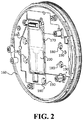
- FIG. 2 shows a rear view of the device 100.
- a housing 160 covers the rear and sides of the device.
- the housing 160 can include an opening 170 that provides access to one or more components of the circuit board 200 housed between the faceplate 110 and housing 160, e.g., a battery component, memory component, etc., that can be exchanged or upgraded.
- the housing 160 can include a plurality of openings 180 that provide access to adjusting screws 190 that can be used to fine tune the faceplate 110 for responsiveness, as will be explained below.
- FIG. 3A shows a top side of the faceplate 110, detached from the device 100.
- the faceplate 110 can be constructed as a single, rigid, seamless component, including an array of openings 135 that allow buttons to protrude through and travel freely.
- the faceplate 110 includes a plurality of depressible portions 115, 116, 117, 118.
- the faceplate 110 includes a total of four depressible portions 115, 116, 117, 118 arranged in quarter positions around the periphery.
- the depressible portions are opaque and can be marked with an indicator to signify to the user the availability and location of the rocker function.
- a single, seamless faceplate reduces the complexity of construction of the device 100. It provides good cosmetics and is easy to manufacture as a single injection molded part.
- the inclusion of the array of openings 135 can weaken the faceplate 110 enough to increase a likelihood of the faceplate 110 flexing rather than remaining rigid when a depressible section is pressed. Such flexing can lead to increased wear and tear as well as detract from the high-quality presentation of the device.
- a stiffening ridge 138 is disposed on the faceplate 110, surrounding the array of openings 135, to enhance a rigid quality of the faceplate 110.
- the depressible portions are translucent such that they allow at least some amount of light to pass through and which indicate which sections of the faceplate 110 can be depressed to utilize the rocker function.
- the translucent depressible portions 115, 116, 117, 118 can be aligned over one or more LEDs controlled by a processor connected to the circuit board 200. In this manner the device 100 can display one or more colors through the depressible portions 115, 116, 117, 118, e.g., according to a status or state of the device, or to indicate availability of certain features.
- the device 100 can be configured such that one of the translucent depressible portions 115 is marked with an outline of a shield icon.
- a red light could indicate to a user that a security feature controlled by the device 100 is currently turned off. While in this state, the user can press the shield icon to activate the security feature.
- the device processor can change the color displayed through the translucent depressible portion 115 from red to green, to indicate to the user that the security feature has been activated.
- FIG. 3B shows a bottom side of the faceplate 110, detached from the device 100.
- the plurality of openings 135 are arranged in an array in a central area of the faceplate.
- the depressible portions 115 are positioned around the plurality of openings 135 along a peripheral area of the faceplate 110.
- a first pair of depressible portions 115, 117 are positioned along a first alignment axis 121, each disposed on opposing sides of the faceplate 110.
- a second pair of depressible portions 116, 118 are positioned on opposing sides of a second alignment axis 122 that is perpendicular to the first alignment axis 121.
- Other embodiments may include a single depressible portion, three or more pairs of depressible portions disposed on opposing ends of respective alignment axis, or other configurations.
- a corresponding plunger 125, 126, 127, 128 is disposed on the bottom side of faceplate 110.
- the plurality of plungers 125, 126, 127, 128 protrude from the bottom surface of the faceplate 110, each toward respective switches on the circuit board 200.
- the faceplate 110 progresses toward the circuit board 200 and causes the corresponding plunger 125, 126, 127, 128 to actuate a switch on the circuit board 200.
- the plungers 125, 126, 127, 128 are positioned such that when pressure is applied at any depressible section near a subject plunger, i.e., to press the faceplate toward the board, only the switch in contact with the subject plunger is actuated while the remaining switches remain open.
- a plurality of bosses 145 are disposed on the bottom side of the faceplate 110. Similar to the plurality of plungers 125, 126, 127, 128, each of the plurality of bosses protrude from the bottom surface of the faceplate 110 toward the circuit board 200.
- FIG. 4 shows a cutaway side view of the faceplate 110, circuit board 200 and housing 160.
- a magnified view shows a boss 145, adjustment screw 190, plunger 125, switch 210, and circuit board opening 220.
- the faceplate 110 is mounted above the circuit board 200 such that plunger 125 rests on top of and in contact with switch 210.
- Switch 210 is a resilient switch that, when pressed, closes a circuit on the circuit board 200 and, when released, automatically returns to its original position.
- Switch 210 can be implemented as a dome-switch, as shown in FIG. 4 , or as a different type of switch, such as a spring-loaded switch or other type of resilient switch that exerts an upward counter-force when pressed down.
- the circuit board 200 includes an opening 220 for each faceplate boss 145.
- the faceplate boss 145 is positioned on the faceplate 110 to be aligned to protrude through the opening 220 when the faceplate 110 is placed over the circuit board 200.
- An adjusting screw 190 is inserted into the boss 145 to secure the faceplate 110 to the circuit board 200 and prevent the faceplate 110 from detaching from the circuit board 200 in an upward direction, i.e., away from the circuit board 200.
- the boss 145/screw 190 arrangement does not prevent the faceplate from moving in a downward direction, i.e., toward the circuit board 200.
- the adjusting screw 190 can be tightened or loosened to tune the contact of the plunger 125 against the switch 210 at each depressible section of the faceplate 110.
- the boss 145/screw 190 combination allows for fine tuning of responsiveness without requiring the use of shims or other additional parts normally used for tuning in a conventional rocker function apparatus.
- boss 145/screw 190 combination references the housing 160.
- boss 145/screw 190 combination references the circuit board 200 directly, thereby reducing the number of layers in the tolerance stack to a minimum compared to conventional rocker mechanisms which can include multiple layers in the tolerance stack, leading to a less consistent button feel in the rocker mechanism.
- the disclosed keypad device provides an improved rocker function with a consistent feel and easily tunable features, as well as improved persistence against wear and tear.
- the disclosed keypad device with a rocker function can include a processor and a memory installed in the circuit board and be used to implement, for example, a security control system, HVAC control system, or a component of a premises management system wherein the central buttons are used for alphanumerical input and the peripheral depressible sections that provide the rocker function input are used to select menus, select operational modes, transmit a signal, change a device parameter such as color or sound, etc.
Landscapes
- Push-Button Switches (AREA)
- Input From Keyboards Or The Like (AREA)
Description
- Various premises management systems (e.g., security systems, HVAC systems, etc.) include a panel or control device configured to receive input from users to control or set settings for the system. The device can include a numerical keypad and an LCD screen to display output. The device can include many mechanical parts that are prone to damage and deterioration over time.
-
WO 2009/133890 A1 discloses a composite switch which comprises a first switch that operates by applying a first load to a first key, and a second switch that operates by applying a second load to a second key disposed on the first key. -
US 2008/316064 A1 discloses an electronic device comprising at least a keypad structure and a printed circuit board. The keypad structure comprises a switch, a keypad body, and a touching element. The keypad body having a through hole is relatively disposed to the switch. The touching element is inserted into the through hole. There is a touching distance defined between the touching element and the switch, and the touching element can be moved relatively to the keypad body for adjusting the touching distance. Also, the printed circuit board is electrically connected to the switch. -
US 2012/044660 A1 discloses a process for characterizing a tactile response of a first mechanical actuator (e.g., button) based on a back off distance. The first mechanical actuator may include a plunger, a dome-shaped flexible membrane, and an electrical contact, all aligned with each other so that a contact signal is generated when the flexible membrane touches the contact. The plunger can be moved a first distance towards the contact until the contact signal is generated at a contact point. Then the plunger can be backed off a second distance from the contact point. - This second distance may be called the "back off distance". The particular feel of the first mechanical actuator can then be correlated to a particular back off distance. This process can be repeated a number of times to classify a number of different "feels" for the first mechanical actuator based on a number of different back off distances.
- According to an embodiment of the disclosed subject matter, a keypad device includes a circuit board having a plurality of raised buttons disposed on a first surface of the circuit board, a plurality of resilient switches disposed on a periphery of the first surface, and a plurality of through-holes, wherein each of the raised buttons and switches, when actuated, closes a circuit on the circuit board and effects an input to the keypad device. The keypad device further includes a faceplate fastened to the circuit board, the faceplate having an array of openings configured to allow the raised buttons to pass through, a plurality of bosses extending from a first surface of the faceplate toward the circuit board and positioned to pass through the plurality of through-holes on the circuit board, and a plurality of plungers aligned above and in contact with the resilient switches such that when the faceplate is pressed toward the circuit board, in a region at or near a subject plunger, the subject plunger actuates the resilient switch that is in contact with the plunger, wherein the faceplate is adjustably secured to the circuit board by screws inserted into the plurality of bosses through a second surface of the circuit board, opposite the first surface of the circuit board. Advantageously, this may provide a durable keypad device whose feel and responsiveness can be fine-tuned easily. Moreover, by providing buttons together with plungers for actuating switches arranged on a periphery of the circuit board, the present disclosure may provide improved usability and/or ergonomics. In some embodiments of the disclosed subject matter, a region on the faceplate may be considered to be near a subject plunger if the region on the faceplate is closer to the subject plunger than it is to any other plunger of the keypad device.
- Optionally, the faceplate comprises one or more translucent portions formed proximal to one or more of the plurality of plungers, and the circuit board comprises one or more LED's disposed beneath the one or more translucent portions such that light from the LED's is visible through the translucent portions. Advantageously, this may enable a user to distinguish the plungers from the buttons more easily, aiding usability.
- The plurality of plungers may comprise four plungers positioned such that when pressure is applied to the faceplate at any subject plunger to press the faceplate toward the board, only the switch in contact with the plunger is actuated while the remaining switches remain open. Thus, a user may be able to exercise control over greater range of functionality than a conventional rocker switch.
- Optionally, two of the plungers are disposed at opposing ends of a first axis that passes through a center of the faceplate and the remaining plungers are disposed at opposing ends of a second axis that passes through the center of the faceplate and is perpendicular to the first axis.
- The faceplate may be constructed of a rigid and seamless material. This may provide good cosmetics and enables the faceplate to be manufactured easily and efficiently as a single injection molded part. Optionally, the faceplate is constructed of a metallic material. This may provide increased strength and durability.
- In some embodiments of the disclosed subject matter, the faceplate may be constructed of a plastic material. In such embodiments, the faceplate may further comprise a stiffening ridge encircling the plurality of openings, wherein the stiffening ridge fortifies the faceplate against bending. This may aid the longevity of the keypad device and provide improved users with improved tactile feedback.
- At least one resilient switch may comprise a resilient, flexible dome structure and/or at least one resilient switch may comprise a spring-loaded switch.
- They keypad device may further comprise a processor configured to implement a security control system. Advantageously, this may provide a user with greater or more convenient control over a security system than conventional keypad devices.
- Additional features, advantages, and embodiments of the disclosed subject matter may be set forth or apparent from consideration of the following detailed description, drawings, and claims. Moreover, it is to be understood that both the foregoing summary and the following detailed description are illustrative and are intended to provide further explanation without limiting the scope of the claims.
- The accompanying drawings, which are included to provide a further understanding of the disclosed subject matter, are incorporated in and constitute a part of this specification. The drawings also illustrate embodiments of the disclosed subject matter and together with the detailed description serve to explain the principles of embodiments of the disclosed subject matter. No attempt is made to show structural details in more detail than may be necessary for a fundamental understanding of the disclosed subject matter and various ways in which it may be practiced.
-
FIG. 1 shows a front perspective view of a keypad device according to an embodiment of the disclosed subject matter. -
FIG. 2 shows a rear perspective view of a keypad device according to an embodiment of the disclosed subject matter. -
FIG. 3A shows a top perspective view of a faceplate according to an embodiment of the disclosed subject matter. -
FIG. 3B shows a bottom perspective view of a faceplate according to an embodiment of the disclosed subject matter. -
FIG. 4 shows a cut-away side view of a keypad device according to an embodiment of the disclosed subject matter with a magnified view. - Various aspects or features of this disclosure are described with reference to the drawings, wherein like reference numerals are used to refer to like elements throughout. In this specification, numerous details are set forth in order to provide a thorough understanding of this disclosure. It should be understood, however, that certain aspects of disclosure may be practiced without these specific details, or with other methods, components, materials, etc. In other instances, well-known structures and devices are shown in block diagram form to facilitate describing the subject disclosure.
- A keypad device having a rocker mechanism according to the disclosed subject matter includes a faceplate cover that functions as multi-directional rocker switch. Compared to conventional rocker mechanisms, the disclosed keypad device requires fewer parts to implement the rocker function, is simpler to manufacture, is less prone to wear and tear through use over time, and provides options for better illuminated indicators at depressible sections of the rocker.
-
FIG. 1 shows a front view of akeypad device 100 according to a disclosed embodiment. The device includes afaceplate 110 with a plurality oficons 120 marking depressible sections of thefaceplate 110. In the embodiment shown, thefaceplate 110 includes four icons, however this is merely a single embodiment, different numbers of icons/depressible sections can be implemented. - The
faceplate 110 includes an array of openings which allow a plurality ofbuttons 130 to protrude through. Each of the buttons and depressible icons are positioned to actuate a switch in a circuit board beneath thefaceplate 110 and thereby input data into thedevice 100, such as, for example, a passcode, a menu selection, or to change a parameter setting, as will be described further below. - To aid in facilitating use of the rocker function an
outer edge 140 of faceplate can be formed to slant upward. This provides the user with a familiar, raised feel which indicates the availability of the rocker function, as well as enhancing the aesthetics of thedevice 100. -
FIG. 2 shows a rear view of thedevice 100. Ahousing 160 covers the rear and sides of the device. Thehousing 160 can include anopening 170 that provides access to one or more components of thecircuit board 200 housed between thefaceplate 110 andhousing 160, e.g., a battery component, memory component, etc., that can be exchanged or upgraded. Thehousing 160 can include a plurality ofopenings 180 that provide access to adjustingscrews 190 that can be used to fine tune thefaceplate 110 for responsiveness, as will be explained below. -
FIG. 3A shows a top side of thefaceplate 110, detached from thedevice 100. Thefaceplate 110 can be constructed as a single, rigid, seamless component, including an array ofopenings 135 that allow buttons to protrude through and travel freely. Thefaceplate 110 includes a plurality ofdepressible portions faceplate 110 includes a total of fourdepressible portions - The use of a single, seamless faceplate reduces the complexity of construction of the
device 100. It provides good cosmetics and is easy to manufacture as a single injection molded part. However, for some construction materials the inclusion of the array ofopenings 135 can weaken thefaceplate 110 enough to increase a likelihood of thefaceplate 110 flexing rather than remaining rigid when a depressible section is pressed. Such flexing can lead to increased wear and tear as well as detract from the high-quality presentation of the device. Accordingly, in some embodiments, an example of which is shown inFIG. 3A , astiffening ridge 138 is disposed on thefaceplate 110, surrounding the array ofopenings 135, to enhance a rigid quality of thefaceplate 110. - In the embodiment shown in
FIGS. 3A and 3B , the depressible portions are translucent such that they allow at least some amount of light to pass through and which indicate which sections of thefaceplate 110 can be depressed to utilize the rocker function. The translucentdepressible portions circuit board 200. In this manner thedevice 100 can display one or more colors through thedepressible portions - For example, in one mode of operation the
device 100 can be configured such that one of the translucentdepressible portions 115 is marked with an outline of a shield icon. A red light could indicate to a user that a security feature controlled by thedevice 100 is currently turned off. While in this state, the user can press the shield icon to activate the security feature. Upon activation the device processor can change the color displayed through the translucentdepressible portion 115 from red to green, to indicate to the user that the security feature has been activated. -
FIG. 3B shows a bottom side of thefaceplate 110, detached from thedevice 100. The plurality ofopenings 135 are arranged in an array in a central area of the faceplate. Thedepressible portions 115 are positioned around the plurality ofopenings 135 along a peripheral area of thefaceplate 110. In this embodiment, a first pair ofdepressible portions first alignment axis 121, each disposed on opposing sides of thefaceplate 110. A second pair ofdepressible portions second alignment axis 122 that is perpendicular to thefirst alignment axis 121. Other embodiments may include a single depressible portion, three or more pairs of depressible portions disposed on opposing ends of respective alignment axis, or other configurations. - At each
depressible portion corresponding plunger faceplate 110. When thefaceplate 110 is secured to thecircuit board 200, the plurality ofplungers faceplate 110, each toward respective switches on thecircuit board 200. Thus, when the top side of thefaceplate 110 is pressed by a user, at or near a depressible portion, 115, 116, 117, 118, thefaceplate 110 progresses toward thecircuit board 200 and causes thecorresponding plunger circuit board 200. - In the embodiment shown in
FIG. 3B , theplungers - A plurality of
bosses 145 are disposed on the bottom side of thefaceplate 110. Similar to the plurality ofplungers faceplate 110 toward thecircuit board 200. -
FIG. 4 shows a cutaway side view of thefaceplate 110,circuit board 200 andhousing 160. A magnified view shows aboss 145,adjustment screw 190,plunger 125,switch 210, andcircuit board opening 220. As seen in the magnified view, thefaceplate 110 is mounted above thecircuit board 200 such thatplunger 125 rests on top of and in contact withswitch 210. -
Switch 210 is a resilient switch that, when pressed, closes a circuit on thecircuit board 200 and, when released, automatically returns to its original position. Switch 210 can be implemented as a dome-switch, as shown inFIG. 4 , or as a different type of switch, such as a spring-loaded switch or other type of resilient switch that exerts an upward counter-force when pressed down. - The
circuit board 200 includes anopening 220 for eachfaceplate boss 145. Thefaceplate boss 145 is positioned on thefaceplate 110 to be aligned to protrude through theopening 220 when thefaceplate 110 is placed over thecircuit board 200. An adjustingscrew 190 is inserted into theboss 145 to secure thefaceplate 110 to thecircuit board 200 and prevent thefaceplate 110 from detaching from thecircuit board 200 in an upward direction, i.e., away from thecircuit board 200. However, theboss 145/screw 190 arrangement does not prevent the faceplate from moving in a downward direction, i.e., toward thecircuit board 200. - In this arrangement, when the
faceplate 110 is pressed at a depressible portion, that portion will descend toward thecircuit board 200, driving theplunger 125 downward into the dome-switch 210. The depression actuates theswitch 210, thereby closing a circuit on thecircuit board 200 and effecting an input to thedevice 100. Theresilient switch 210, upon being pressed down, exerts a counter-force upward to return to its initial state. Thus, when the user refrains from pressing thefaceplate 110, theswitch 210 forces theplunger 125, and by extension thefaceplate 110, up to the faceplate's 110 original resting position. - The adjusting
screw 190 can be tightened or loosened to tune the contact of theplunger 125 against theswitch 210 at each depressible section of thefaceplate 110. Theboss 145/screw 190 combination allows for fine tuning of responsiveness without requiring the use of shims or other additional parts normally used for tuning in a conventional rocker function apparatus. - In an embodiment the
boss 145/screw 190 combination references thehousing 160. In an alternate embodiment theboss 145/screw 190 combination references thecircuit board 200 directly, thereby reducing the number of layers in the tolerance stack to a minimum compared to conventional rocker mechanisms which can include multiple layers in the tolerance stack, leading to a less consistent button feel in the rocker mechanism. - The disclosed keypad device provides an improved rocker function with a consistent feel and easily tunable features, as well as improved persistence against wear and tear. The disclosed keypad device with a rocker function can include a processor and a memory installed in the circuit board and be used to implement, for example, a security control system, HVAC control system, or a component of a premises management system wherein the central buttons are used for alphanumerical input and the peripheral depressible sections that provide the rocker function input are used to select menus, select operational modes, transmit a signal, change a device parameter such as color or sound, etc.
- The foregoing description, for purpose of explanation, has been described with reference to specific embodiments. However, the illustrative discussions above are not intended to be exhaustive or to limit embodiments of the disclosed subject matter to the precise forms disclosed. Many modifications and variations are possible in view of the above teachings. The embodiments were chosen and described in order to explain the principles of embodiments of the disclosed subject matter and their practical applications, to thereby enable others skilled in the art to utilize those embodiments as well as various embodiments with various modifications as may be suited to the particular use contemplated.
Claims (11)
- A keypad device (100), comprising:a circuit board (200) having:a plurality of raised buttons (130) disposed on a first surface of the circuit board (200),a plurality of resilient switches (210) disposed on a periphery of the first surface, anda plurality of through-holes,wherein each of the raised buttons (130) and switches (210), when actuated, closes a circuit on the circuit board (200) and effects an input to the keypad device (100);anda faceplate (110) fastened to the circuit board (200), the faceplate (110) having:an array of openings (135) configured to allow the raised buttons (130) to pass through,a plurality of bosses (145) extending from a first surface of the faceplate (110) toward the circuit board (200) and positioned to pass through the plurality of through-holes on the circuit board (200), anda plurality of plungers (125, 126, 127, 128) aligned above and in contact with the resilient switches (210) such that when the faceplate is pressed toward the circuit board (200), in a region at or near a subject plunger (125, 126, 127, 128), the subject plunger (125, 126, 127, 128) actuates the resilient switch (210) that is in contact with the subject plunger (125, 126, 127, 128),wherein the faceplate (110) is adjustably secured to the circuit board by screws (190) inserted into the plurality of bosses (145) through a second surface of the circuit board (200), opposite the first surface of the circuit board (200).
- The keypad device (100) of claim 1, wherein:the faceplate (110) comprises one or more translucent portions (115, 116, 117, 118) formed proximal to one or more of the plurality of plungers (125, 126, 127, 128); andthe circuit board comprises (200) one or more LED's disposed beneath the one or more translucent portions (115, 116, 117, 118) such that light from the LED's is visible through the translucent portions (115, 116, 117, 118).
- The keypad device (100) of claim 1 or claim 2, wherein the plurality of plungers (125, 126, 127, 128) comprise four plungers positioned such that when pressure is applied to the faceplate (110) at any subject plunger (125, 126, 127, 128) to press the faceplate (110) toward the board, only the switch (210) in contact with the plunger (125, 126, 127, 128) is actuated while the remaining switches (210) remain open.
- The keypad device (100) of claim 3, wherein two of the plungers (125, 126, 127, 128) are disposed at opposing ends of a first axis that passes through a center of the faceplate (110) and the remaining plungers (125, 126, 127, 128) are disposed at opposing ends of a second axis that passes through the center of the faceplate (110) and is perpendicular to the first axis.
- The keypad device (100) of any preceding claim, wherein the faceplate (110) is constructed of a rigid and seamless material.
- The keypad device (100) of any preceding claim, wherein the faceplate (110) is constructed of a metallic material.
- The keypad device (100) of any of claims 1 to 5, wherein the faceplate (110) is constructed of a plastic material.
- The keypad device (100) of any preceding claim, wherein the faceplate (110) further comprises a stiffening ridge (138) encircling the plurality of openings (135), wherein the stiffening ridge (138) fortifies the faceplate (110) against bending.
- The keypad device (100) of any preceding claim, wherein at least one resilient switch (210) comprises a resilient, flexible dome structure.
- The keypad device (100) of any preceding claim, wherein at least one resilient switch (210) comprises a spring-loaded switch.
- They keypad device (100) of any preceding claim, further comprising a processor configured to implement a security control system.
Applications Claiming Priority (2)
| Application Number | Priority Date | Filing Date | Title |
|---|---|---|---|
| US15/800,012 US10276324B1 (en) | 2017-10-31 | 2017-10-31 | Keypad device with rocker button mechanism |
| PCT/US2018/040338 WO2019089093A1 (en) | 2017-10-31 | 2018-06-29 | Keypad device with rocker button mechanism |
Publications (2)
| Publication Number | Publication Date |
|---|---|
| EP3619729A1 EP3619729A1 (en) | 2020-03-11 |
| EP3619729B1 true EP3619729B1 (en) | 2020-08-19 |
Family
ID=62976344
Family Applications (1)
| Application Number | Title | Priority Date | Filing Date |
|---|---|---|---|
| EP18743341.2A Active EP3619729B1 (en) | 2017-10-31 | 2018-06-29 | Keypad device with rocker button mechanism |
Country Status (4)
| Country | Link |
|---|---|
| US (2) | US10276324B1 (en) |
| EP (1) | EP3619729B1 (en) |
| CN (2) | CN110709954B (en) |
| WO (1) | WO2019089093A1 (en) |
Family Cites Families (41)
| Publication number | Priority date | Publication date | Assignee | Title |
|---|---|---|---|---|
| JPS56147540U (en) * | 1980-04-04 | 1981-11-06 | ||
| US4618744A (en) | 1985-04-29 | 1986-10-21 | Advanced Input Devices, Inc. | Rocker key elastomer dome keyboard |
| US4980522A (en) * | 1988-06-13 | 1990-12-25 | Mitsubishi Denki Kabiushiki Kaisha | Operating key switch unit |
| US5734136A (en) * | 1996-06-12 | 1998-03-31 | Qualcomm Incorporated | Keypad assembly with moisture-excluding seal |
| JP4006552B2 (en) * | 1998-02-02 | 2007-11-14 | 富士フイルム株式会社 | Electronic device dial control unit structure |
| JP2000215761A (en) * | 1999-01-22 | 2000-08-04 | Kenwood Corp | Multi-directional operation key structure |
| DE10107572C1 (en) * | 2001-02-17 | 2002-10-24 | Loewe Opta Gmbh | Multi-directional function switch for control device has operating element deflected sidewards during its depression for coupling concentric ring contact to different ring segment contacts |
| US6925315B2 (en) | 2001-10-30 | 2005-08-02 | Fred Langford | Telephone handset with thumb-operated tactile keypad |
| US6657141B1 (en) | 2002-11-12 | 2003-12-02 | Mitsuku Denshi Kogyo K.K. | Four-way slide switch |
| CN2664144Y (en) * | 2003-11-12 | 2004-12-15 | 金宝电子工业股份有限公司 | Polydirectional push-button structure |
| KR100597008B1 (en) * | 2004-03-09 | 2006-07-06 | 삼성전자주식회사 | Electronic Keys |
| US7084360B2 (en) * | 2004-07-28 | 2006-08-01 | Lear Corporation | Elastomeric vehicle control switch |
| JP4448020B2 (en) | 2004-12-21 | 2010-04-07 | サンアロー株式会社 | Direction detection switch |
| US7629548B2 (en) * | 2005-07-14 | 2009-12-08 | Access Business Group International Llc | Control panel assembly |
| US20070086825A1 (en) | 2005-10-15 | 2007-04-19 | Min Byung K | Circular keyboard |
| CN1979706A (en) * | 2005-11-29 | 2007-06-13 | 乐金电子(天津)电器有限公司 | Button fitting structure of drum washer control panel assembly |
| CN2886781Y (en) * | 2006-02-10 | 2007-04-04 | 鸿富锦精密工业(深圳)有限公司 | Power supply key module structure |
| KR100827621B1 (en) * | 2006-04-27 | 2008-05-07 | 삼성전기주식회사 | Input device |
| KR101176943B1 (en) * | 2006-05-09 | 2012-08-30 | 삼성전자주식회사 | A function key assembly for fortable device |
| US7663070B2 (en) | 2006-06-30 | 2010-02-16 | Avaya Inc. | Four-way rocker switch with display |
| US7795553B2 (en) * | 2006-09-11 | 2010-09-14 | Apple Inc. | Hybrid button |
| US7425686B1 (en) | 2007-01-25 | 2008-09-16 | Ford Global Technologies, Llc | Four-way rocker switch |
| TWI335603B (en) | 2007-06-25 | 2011-01-01 | Benq Corp | Keypad structure and electronic device using the same |
| CN101441954B (en) * | 2007-11-23 | 2011-05-11 | 上海乐金广电电子有限公司 | Lever type key structure |
| CN101459003A (en) * | 2007-12-13 | 2009-06-17 | 鸿富锦精密工业(深圳)有限公司 | Press-key component and electronic device using the component |
| WO2009094804A1 (en) * | 2008-01-24 | 2009-08-06 | Panasonic Corporation | Key switch and electronic device |
| CN101971276B (en) | 2008-04-28 | 2014-03-19 | 日本电气株式会社 | Composite switch and portable device with same |
| CN101587792A (en) | 2008-05-21 | 2009-11-25 | 深圳富泰宏精密工业有限公司 | The portable electron device of Keysheet module, this Keysheet module of tool and method for inputting characters with great |
| CN201210774Y (en) * | 2008-06-04 | 2009-03-18 | 贵州航天乌江科技有限责任公司 | High-reliability electronic controller |
| DE102009000536A1 (en) * | 2009-02-02 | 2010-08-05 | Ford Global Technologies, LLC, Dearborn | Modular light switch unit for controlling lighting groups for motor vehicle, has modular operating elements designed as switches, and main switch for switching on and off headlights enclosed by smaller switch |
| SE534890C2 (en) * | 2009-05-06 | 2012-02-07 | Scania Cv Ab | Device for operating a suspension level system in a vehicle |
| FR2957692B1 (en) * | 2010-03-17 | 2012-06-08 | Delphi Tech Inc | RETRO-LIGHT ROTARY SWITCH CONTROL DEVICE BY A LIGHT GUIDE |
| US8420965B2 (en) | 2010-08-17 | 2013-04-16 | Apple Inc. | Button assembly with drive assembly |
| JP5720224B2 (en) * | 2010-12-14 | 2015-05-20 | ヤマハ株式会社 | Switch structure, electronic component installation structure, and electronic musical instrument including the same |
| TWI434312B (en) * | 2011-03-09 | 2014-04-11 | Delta Electronics Inc | Keyswitch controller |
| CN202068461U (en) * | 2011-05-06 | 2011-12-07 | 中兴通讯股份有限公司 | Terminal keyboard structure and terminal |
| KR101425949B1 (en) * | 2012-08-24 | 2014-08-05 | (주)아이티버스 | Pushing type signal input device |
| DE102013205689B3 (en) * | 2013-03-28 | 2014-09-25 | Continental Automotive Gmbh | Portable electronic user device |
| CN205306207U (en) * | 2015-01-15 | 2016-06-15 | 吕岳敏 | Electronic product turns over box -like protective sheath with keyboard |
| CN105931906B (en) * | 2016-06-16 | 2018-08-28 | 东莞市新七甲电子科技有限公司 | Elastic adjustable key |
| CN206059242U (en) * | 2016-09-27 | 2017-03-29 | 广东欧珀移动通信有限公司 | Silica gel push-button and the combination button containing the silica gel push-button and electronic product |
-
2017
- 2017-10-31 US US15/800,012 patent/US10276324B1/en active Active
-
2018
- 2018-06-29 CN CN201880036947.4A patent/CN110709954B/en active Active
- 2018-06-29 WO PCT/US2018/040338 patent/WO2019089093A1/en not_active Ceased
- 2018-06-29 EP EP18743341.2A patent/EP3619729B1/en active Active
- 2018-06-29 CN CN202210102646.5A patent/CN114420488A/en active Pending
-
2019
- 2019-02-25 US US16/284,225 patent/US10741343B2/en active Active
Non-Patent Citations (1)
| Title |
|---|
| None * |
Also Published As
| Publication number | Publication date |
|---|---|
| EP3619729A1 (en) | 2020-03-11 |
| US20190131086A1 (en) | 2019-05-02 |
| US10276324B1 (en) | 2019-04-30 |
| US20190189372A1 (en) | 2019-06-20 |
| WO2019089093A1 (en) | 2019-05-09 |
| CN110709954A (en) | 2020-01-17 |
| CN114420488A (en) | 2022-04-29 |
| CN110709954B (en) | 2022-02-18 |
| US10741343B2 (en) | 2020-08-11 |
Similar Documents
| Publication | Publication Date | Title |
|---|---|---|
| US7916002B2 (en) | Haptic operative user interface input apparatus | |
| CA2412243C (en) | Keyboard assembly for a mobile device | |
| US8502092B2 (en) | Rotary switch mechanism | |
| US5982355A (en) | Multiple purpose controls for electrical systems | |
| EP3752382B1 (en) | A multifunctional switch device | |
| US20070018965A1 (en) | Illuminated touch control interface | |
| US6525279B2 (en) | Switching device | |
| JP4190568B1 (en) | Mobile device | |
| JP2007523456A (en) | switch | |
| US20180197697A1 (en) | Slim-type key structure | |
| US20160268073A1 (en) | Keyboard device | |
| US10276324B1 (en) | Keypad device with rocker button mechanism | |
| JP4977538B2 (en) | 4-way rocker switch with display | |
| US9024791B2 (en) | Input device with rotary wheel | |
| US8717201B2 (en) | Electronic device | |
| KR100863311B1 (en) | Control panel assembly | |
| JP2026068542A (en) | Keyboard and operating device | |
| JP2005158579A (en) | Electronic equipment | |
| US6377756B1 (en) | Operation button used for portable apparatus | |
| KR100465305B1 (en) | Button type switch | |
| KR20060026348A (en) | Keypad with key interlock prevention function and portable terminal having the same | |
| KR100459772B1 (en) | Key button assembly | |
| KR20040107768A (en) | Mobile terminal having function of touch pad |
Legal Events
| Date | Code | Title | Description |
|---|---|---|---|
| STAA | Information on the status of an ep patent application or granted ep patent |
Free format text: STATUS: UNKNOWN |
|
| STAA | Information on the status of an ep patent application or granted ep patent |
Free format text: STATUS: THE INTERNATIONAL PUBLICATION HAS BEEN MADE |
|
| PUAI | Public reference made under article 153(3) epc to a published international application that has entered the european phase |
Free format text: ORIGINAL CODE: 0009012 |
|
| STAA | Information on the status of an ep patent application or granted ep patent |
Free format text: STATUS: REQUEST FOR EXAMINATION WAS MADE |
|
| 17P | Request for examination filed |
Effective date: 20191206 |
|
| AK | Designated contracting states |
Kind code of ref document: A1 Designated state(s): AL AT BE BG CH CY CZ DE DK EE ES FI FR GB GR HR HU IE IS IT LI LT LU LV MC MK MT NL NO PL PT RO RS SE SI SK SM TR |
|
| AX | Request for extension of the european patent |
Extension state: BA ME |
|
| GRAP | Despatch of communication of intention to grant a patent |
Free format text: ORIGINAL CODE: EPIDOSNIGR1 |
|
| STAA | Information on the status of an ep patent application or granted ep patent |
Free format text: STATUS: GRANT OF PATENT IS INTENDED |
|
| DAV | Request for validation of the european patent (deleted) | ||
| DAX | Request for extension of the european patent (deleted) | ||
| INTG | Intention to grant announced |
Effective date: 20200313 |
|
| GRAS | Grant fee paid |
Free format text: ORIGINAL CODE: EPIDOSNIGR3 |
|
| GRAA | (expected) grant |
Free format text: ORIGINAL CODE: 0009210 |
|
| STAA | Information on the status of an ep patent application or granted ep patent |
Free format text: STATUS: THE PATENT HAS BEEN GRANTED |
|
| AK | Designated contracting states |
Kind code of ref document: B1 Designated state(s): AL AT BE BG CH CY CZ DE DK EE ES FI FR GB GR HR HU IE IS IT LI LT LU LV MC MK MT NL NO PL PT RO RS SE SI SK SM TR |
|
| REG | Reference to a national code |
Ref country code: CH Ref legal event code: EP |
|
| REG | Reference to a national code |
Ref country code: DE Ref legal event code: R096 Ref document number: 602018007132 Country of ref document: DE |
|
| REG | Reference to a national code |
Ref country code: AT Ref legal event code: REF Ref document number: 1304890 Country of ref document: AT Kind code of ref document: T Effective date: 20200915 |
|
| REG | Reference to a national code |
Ref country code: IE Ref legal event code: FG4D |
|
| REG | Reference to a national code |
Ref country code: LT Ref legal event code: MG4D |
|
| REG | Reference to a national code |
Ref country code: NL Ref legal event code: MP Effective date: 20200819 |
|
| PG25 | Lapsed in a contracting state [announced via postgrant information from national office to epo] |
Ref country code: SE Free format text: LAPSE BECAUSE OF FAILURE TO SUBMIT A TRANSLATION OF THE DESCRIPTION OR TO PAY THE FEE WITHIN THE PRESCRIBED TIME-LIMIT Effective date: 20200819 Ref country code: LT Free format text: LAPSE BECAUSE OF FAILURE TO SUBMIT A TRANSLATION OF THE DESCRIPTION OR TO PAY THE FEE WITHIN THE PRESCRIBED TIME-LIMIT Effective date: 20200819 Ref country code: PT Free format text: LAPSE BECAUSE OF FAILURE TO SUBMIT A TRANSLATION OF THE DESCRIPTION OR TO PAY THE FEE WITHIN THE PRESCRIBED TIME-LIMIT Effective date: 20201221 Ref country code: HR Free format text: LAPSE BECAUSE OF FAILURE TO SUBMIT A TRANSLATION OF THE DESCRIPTION OR TO PAY THE FEE WITHIN THE PRESCRIBED TIME-LIMIT Effective date: 20200819 Ref country code: GR Free format text: LAPSE BECAUSE OF FAILURE TO SUBMIT A TRANSLATION OF THE DESCRIPTION OR TO PAY THE FEE WITHIN THE PRESCRIBED TIME-LIMIT Effective date: 20201120 Ref country code: FI Free format text: LAPSE BECAUSE OF FAILURE TO SUBMIT A TRANSLATION OF THE DESCRIPTION OR TO PAY THE FEE WITHIN THE PRESCRIBED TIME-LIMIT Effective date: 20200819 Ref country code: NO Free format text: LAPSE BECAUSE OF FAILURE TO SUBMIT A TRANSLATION OF THE DESCRIPTION OR TO PAY THE FEE WITHIN THE PRESCRIBED TIME-LIMIT Effective date: 20201119 Ref country code: BG Free format text: LAPSE BECAUSE OF FAILURE TO SUBMIT A TRANSLATION OF THE DESCRIPTION OR TO PAY THE FEE WITHIN THE PRESCRIBED TIME-LIMIT Effective date: 20201119 |
|
| REG | Reference to a national code |
Ref country code: AT Ref legal event code: MK05 Ref document number: 1304890 Country of ref document: AT Kind code of ref document: T Effective date: 20200819 |
|
| PG25 | Lapsed in a contracting state [announced via postgrant information from national office to epo] |
Ref country code: NL Free format text: LAPSE BECAUSE OF FAILURE TO SUBMIT A TRANSLATION OF THE DESCRIPTION OR TO PAY THE FEE WITHIN THE PRESCRIBED TIME-LIMIT Effective date: 20200819 Ref country code: RS Free format text: LAPSE BECAUSE OF FAILURE TO SUBMIT A TRANSLATION OF THE DESCRIPTION OR TO PAY THE FEE WITHIN THE PRESCRIBED TIME-LIMIT Effective date: 20200819 Ref country code: PL Free format text: LAPSE BECAUSE OF FAILURE TO SUBMIT A TRANSLATION OF THE DESCRIPTION OR TO PAY THE FEE WITHIN THE PRESCRIBED TIME-LIMIT Effective date: 20200819 Ref country code: LV Free format text: LAPSE BECAUSE OF FAILURE TO SUBMIT A TRANSLATION OF THE DESCRIPTION OR TO PAY THE FEE WITHIN THE PRESCRIBED TIME-LIMIT Effective date: 20200819 Ref country code: IS Free format text: LAPSE BECAUSE OF FAILURE TO SUBMIT A TRANSLATION OF THE DESCRIPTION OR TO PAY THE FEE WITHIN THE PRESCRIBED TIME-LIMIT Effective date: 20201219 |
|
| PG25 | Lapsed in a contracting state [announced via postgrant information from national office to epo] |
Ref country code: SM Free format text: LAPSE BECAUSE OF FAILURE TO SUBMIT A TRANSLATION OF THE DESCRIPTION OR TO PAY THE FEE WITHIN THE PRESCRIBED TIME-LIMIT Effective date: 20200819 Ref country code: EE Free format text: LAPSE BECAUSE OF FAILURE TO SUBMIT A TRANSLATION OF THE DESCRIPTION OR TO PAY THE FEE WITHIN THE PRESCRIBED TIME-LIMIT Effective date: 20200819 Ref country code: RO Free format text: LAPSE BECAUSE OF FAILURE TO SUBMIT A TRANSLATION OF THE DESCRIPTION OR TO PAY THE FEE WITHIN THE PRESCRIBED TIME-LIMIT Effective date: 20200819 Ref country code: DK Free format text: LAPSE BECAUSE OF FAILURE TO SUBMIT A TRANSLATION OF THE DESCRIPTION OR TO PAY THE FEE WITHIN THE PRESCRIBED TIME-LIMIT Effective date: 20200819 Ref country code: CZ Free format text: LAPSE BECAUSE OF FAILURE TO SUBMIT A TRANSLATION OF THE DESCRIPTION OR TO PAY THE FEE WITHIN THE PRESCRIBED TIME-LIMIT Effective date: 20200819 |
|
| REG | Reference to a national code |
Ref country code: DE Ref legal event code: R097 Ref document number: 602018007132 Country of ref document: DE |
|
| PG25 | Lapsed in a contracting state [announced via postgrant information from national office to epo] |
Ref country code: AL Free format text: LAPSE BECAUSE OF FAILURE TO SUBMIT A TRANSLATION OF THE DESCRIPTION OR TO PAY THE FEE WITHIN THE PRESCRIBED TIME-LIMIT Effective date: 20200819 Ref country code: AT Free format text: LAPSE BECAUSE OF FAILURE TO SUBMIT A TRANSLATION OF THE DESCRIPTION OR TO PAY THE FEE WITHIN THE PRESCRIBED TIME-LIMIT Effective date: 20200819 Ref country code: ES Free format text: LAPSE BECAUSE OF FAILURE TO SUBMIT A TRANSLATION OF THE DESCRIPTION OR TO PAY THE FEE WITHIN THE PRESCRIBED TIME-LIMIT Effective date: 20200819 |
|
| PLBE | No opposition filed within time limit |
Free format text: ORIGINAL CODE: 0009261 |
|
| STAA | Information on the status of an ep patent application or granted ep patent |
Free format text: STATUS: NO OPPOSITION FILED WITHIN TIME LIMIT |
|
| PG25 | Lapsed in a contracting state [announced via postgrant information from national office to epo] |
Ref country code: SK Free format text: LAPSE BECAUSE OF FAILURE TO SUBMIT A TRANSLATION OF THE DESCRIPTION OR TO PAY THE FEE WITHIN THE PRESCRIBED TIME-LIMIT Effective date: 20200819 |
|
| 26N | No opposition filed |
Effective date: 20210520 |
|
| PG25 | Lapsed in a contracting state [announced via postgrant information from national office to epo] |
Ref country code: IT Free format text: LAPSE BECAUSE OF FAILURE TO SUBMIT A TRANSLATION OF THE DESCRIPTION OR TO PAY THE FEE WITHIN THE PRESCRIBED TIME-LIMIT Effective date: 20200819 |
|
| PG25 | Lapsed in a contracting state [announced via postgrant information from national office to epo] |
Ref country code: MC Free format text: LAPSE BECAUSE OF FAILURE TO SUBMIT A TRANSLATION OF THE DESCRIPTION OR TO PAY THE FEE WITHIN THE PRESCRIBED TIME-LIMIT Effective date: 20200819 |
|
| REG | Reference to a national code |
Ref country code: CH Ref legal event code: PL |
|
| REG | Reference to a national code |
Ref country code: BE Ref legal event code: MM Effective date: 20210630 |
|
| PG25 | Lapsed in a contracting state [announced via postgrant information from national office to epo] |
Ref country code: LU Free format text: LAPSE BECAUSE OF NON-PAYMENT OF DUE FEES Effective date: 20210629 |
|
| PG25 | Lapsed in a contracting state [announced via postgrant information from national office to epo] |
Ref country code: LI Free format text: LAPSE BECAUSE OF NON-PAYMENT OF DUE FEES Effective date: 20210630 Ref country code: IE Free format text: LAPSE BECAUSE OF NON-PAYMENT OF DUE FEES Effective date: 20210629 Ref country code: CH Free format text: LAPSE BECAUSE OF NON-PAYMENT OF DUE FEES Effective date: 20210630 |
|
| PG25 | Lapsed in a contracting state [announced via postgrant information from national office to epo] |
Ref country code: BE Free format text: LAPSE BECAUSE OF NON-PAYMENT OF DUE FEES Effective date: 20210630 |
|
| PG25 | Lapsed in a contracting state [announced via postgrant information from national office to epo] |
Ref country code: CY Free format text: LAPSE BECAUSE OF FAILURE TO SUBMIT A TRANSLATION OF THE DESCRIPTION OR TO PAY THE FEE WITHIN THE PRESCRIBED TIME-LIMIT Effective date: 20200819 |
|
| PG25 | Lapsed in a contracting state [announced via postgrant information from national office to epo] |
Ref country code: HU Free format text: LAPSE BECAUSE OF FAILURE TO SUBMIT A TRANSLATION OF THE DESCRIPTION OR TO PAY THE FEE WITHIN THE PRESCRIBED TIME-LIMIT; INVALID AB INITIO Effective date: 20180629 |
|
| PG25 | Lapsed in a contracting state [announced via postgrant information from national office to epo] |
Ref country code: SI Free format text: LAPSE BECAUSE OF FAILURE TO SUBMIT A TRANSLATION OF THE DESCRIPTION OR TO PAY THE FEE WITHIN THE PRESCRIBED TIME-LIMIT Effective date: 20200819 |
|
| PG25 | Lapsed in a contracting state [announced via postgrant information from national office to epo] |
Ref country code: MK Free format text: LAPSE BECAUSE OF FAILURE TO SUBMIT A TRANSLATION OF THE DESCRIPTION OR TO PAY THE FEE WITHIN THE PRESCRIBED TIME-LIMIT Effective date: 20200819 |
|
| PG25 | Lapsed in a contracting state [announced via postgrant information from national office to epo] |
Ref country code: MT Free format text: LAPSE BECAUSE OF FAILURE TO SUBMIT A TRANSLATION OF THE DESCRIPTION OR TO PAY THE FEE WITHIN THE PRESCRIBED TIME-LIMIT Effective date: 20200819 |
|
| PG25 | Lapsed in a contracting state [announced via postgrant information from national office to epo] |
Ref country code: TR Free format text: LAPSE BECAUSE OF FAILURE TO SUBMIT A TRANSLATION OF THE DESCRIPTION OR TO PAY THE FEE WITHIN THE PRESCRIBED TIME-LIMIT Effective date: 20200819 |
|
| PGFP | Annual fee paid to national office [announced via postgrant information from national office to epo] |
Ref country code: GB Payment date: 20260629 Year of fee payment: 9 |
|
| PGFP | Annual fee paid to national office [announced via postgrant information from national office to epo] |
Ref country code: DE Payment date: 20260629 Year of fee payment: 9 |
|
| PGFP | Annual fee paid to national office [announced via postgrant information from national office to epo] |
Ref country code: FR Payment date: 20260625 Year of fee payment: 9 |