EP3619583B1 - Diagnostic systems and methods for isolating failure modes of a vehicle - Google Patents
Diagnostic systems and methods for isolating failure modes of a vehicle Download PDFInfo
- Publication number
- EP3619583B1 EP3619583B1 EP17912733.7A EP17912733A EP3619583B1 EP 3619583 B1 EP3619583 B1 EP 3619583B1 EP 17912733 A EP17912733 A EP 17912733A EP 3619583 B1 EP3619583 B1 EP 3619583B1
- Authority
- EP
- European Patent Office
- Prior art keywords
- engine
- sensor
- data
- engine speed
- speed
- Prior art date
- Legal status (The legal status is an assumption and is not a legal conclusion. Google has not performed a legal analysis and makes no representation as to the accuracy of the status listed.)
- Active
Links
Images



Classifications
-
- F—MECHANICAL ENGINEERING; LIGHTING; HEATING; WEAPONS; BLASTING
- F02—COMBUSTION ENGINES; HOT-GAS OR COMBUSTION-PRODUCT ENGINE PLANTS
- F02D—CONTROLLING COMBUSTION ENGINES
- F02D41/00—Electrical control of supply of combustible mixture or its constituents
- F02D41/22—Safety or indicating devices for abnormal conditions
- F02D41/221—Safety or indicating devices for abnormal conditions relating to the failure of actuators or electrically driven elements
-
- F—MECHANICAL ENGINEERING; LIGHTING; HEATING; WEAPONS; BLASTING
- F02—COMBUSTION ENGINES; HOT-GAS OR COMBUSTION-PRODUCT ENGINE PLANTS
- F02D—CONTROLLING COMBUSTION ENGINES
- F02D41/00—Electrical control of supply of combustible mixture or its constituents
- F02D41/22—Safety or indicating devices for abnormal conditions
-
- F—MECHANICAL ENGINEERING; LIGHTING; HEATING; WEAPONS; BLASTING
- F02—COMBUSTION ENGINES; HOT-GAS OR COMBUSTION-PRODUCT ENGINE PLANTS
- F02B—INTERNAL-COMBUSTION PISTON ENGINES; COMBUSTION ENGINES IN GENERAL
- F02B37/00—Engines characterised by provision of pumps driven at least for part of the time by exhaust
- F02B37/12—Control of the pumps
- F02B37/16—Control of the pumps by bypassing charging air
-
- F—MECHANICAL ENGINEERING; LIGHTING; HEATING; WEAPONS; BLASTING
- F02—COMBUSTION ENGINES; HOT-GAS OR COMBUSTION-PRODUCT ENGINE PLANTS
- F02D—CONTROLLING COMBUSTION ENGINES
- F02D41/00—Electrical control of supply of combustible mixture or its constituents
- F02D41/22—Safety or indicating devices for abnormal conditions
- F02D41/222—Safety or indicating devices for abnormal conditions relating to the failure of sensors or parameter detection devices
-
- G—PHYSICS
- G01—MEASURING; TESTING
- G01M—TESTING STATIC OR DYNAMIC BALANCE OF MACHINES OR STRUCTURES; TESTING OF STRUCTURES OR APPARATUS, NOT OTHERWISE PROVIDED FOR
- G01M15/00—Testing of engines
- G01M15/04—Testing internal-combustion engines
- G01M15/05—Testing internal-combustion engines by combined monitoring of two or more different engine parameters
-
- G—PHYSICS
- G05—CONTROLLING; REGULATING
- G05B—CONTROL OR REGULATING SYSTEMS IN GENERAL; FUNCTIONAL ELEMENTS OF SUCH SYSTEMS; MONITORING OR TESTING ARRANGEMENTS FOR SUCH SYSTEMS OR ELEMENTS
- G05B23/00—Testing or monitoring of control systems or parts thereof
- G05B23/02—Electric testing or monitoring
- G05B23/0205—Electric testing or monitoring by means of a monitoring system capable of detecting and responding to faults
- G05B23/0259—Electric testing or monitoring by means of a monitoring system capable of detecting and responding to faults characterized by the response to fault detection
- G05B23/0275—Fault isolation and identification, e.g. classify fault; estimate cause or root of failure
-
- G—PHYSICS
- G05—CONTROLLING; REGULATING
- G05B—CONTROL OR REGULATING SYSTEMS IN GENERAL; FUNCTIONAL ELEMENTS OF SUCH SYSTEMS; MONITORING OR TESTING ARRANGEMENTS FOR SUCH SYSTEMS OR ELEMENTS
- G05B23/00—Testing or monitoring of control systems or parts thereof
- G05B23/02—Electric testing or monitoring
- G05B23/0205—Electric testing or monitoring by means of a monitoring system capable of detecting and responding to faults
- G05B23/0259—Electric testing or monitoring by means of a monitoring system capable of detecting and responding to faults characterized by the response to fault detection
- G05B23/0286—Modifications to the monitored process, e.g. stopping operation or adapting control
- G05B23/0289—Reconfiguration to prevent failure, e.g. usually as a reaction to incipient failure detection
-
- G—PHYSICS
- G07—CHECKING-DEVICES
- G07C—TIME OR ATTENDANCE REGISTERS; REGISTERING OR INDICATING THE WORKING OF MACHINES; GENERATING RANDOM NUMBERS; VOTING OR LOTTERY APPARATUS; ARRANGEMENTS, SYSTEMS OR APPARATUS FOR CHECKING NOT PROVIDED FOR ELSEWHERE
- G07C5/00—Registering or indicating the working of vehicles
- G07C5/08—Registering or indicating performance data other than driving, working, idle, or waiting time, with or without registering driving, working, idle or waiting time
- G07C5/0808—Diagnosing performance data
-
- G—PHYSICS
- G07—CHECKING-DEVICES
- G07C—TIME OR ATTENDANCE REGISTERS; REGISTERING OR INDICATING THE WORKING OF MACHINES; GENERATING RANDOM NUMBERS; VOTING OR LOTTERY APPARATUS; ARRANGEMENTS, SYSTEMS OR APPARATUS FOR CHECKING NOT PROVIDED FOR ELSEWHERE
- G07C5/00—Registering or indicating the working of vehicles
- G07C5/08—Registering or indicating performance data other than driving, working, idle, or waiting time, with or without registering driving, working, idle or waiting time
- G07C5/0816—Indicating performance data, e.g. occurrence of a malfunction
- G07C5/0825—Indicating performance data, e.g. occurrence of a malfunction using optical means
-
- F—MECHANICAL ENGINEERING; LIGHTING; HEATING; WEAPONS; BLASTING
- F02—COMBUSTION ENGINES; HOT-GAS OR COMBUSTION-PRODUCT ENGINE PLANTS
- F02D—CONTROLLING COMBUSTION ENGINES
- F02D41/00—Electrical control of supply of combustible mixture or its constituents
- F02D41/22—Safety or indicating devices for abnormal conditions
- F02D2041/227—Limping Home, i.e. taking specific engine control measures at abnormal conditions
-
- F—MECHANICAL ENGINEERING; LIGHTING; HEATING; WEAPONS; BLASTING
- F02—COMBUSTION ENGINES; HOT-GAS OR COMBUSTION-PRODUCT ENGINE PLANTS
- F02D—CONTROLLING COMBUSTION ENGINES
- F02D41/00—Electrical control of supply of combustible mixture or its constituents
- F02D41/22—Safety or indicating devices for abnormal conditions
- F02D2041/228—Warning displays
-
- F—MECHANICAL ENGINEERING; LIGHTING; HEATING; WEAPONS; BLASTING
- F02—COMBUSTION ENGINES; HOT-GAS OR COMBUSTION-PRODUCT ENGINE PLANTS
- F02D—CONTROLLING COMBUSTION ENGINES
- F02D41/00—Electrical control of supply of combustible mixture or its constituents
- F02D41/24—Electrical control of supply of combustible mixture or its constituents characterised by the use of digital means
- F02D41/26—Electrical control of supply of combustible mixture or its constituents characterised by the use of digital means using computer, e.g. microprocessor
- F02D41/28—Interface circuits
- F02D2041/281—Interface circuits between sensors and control unit
-
- F—MECHANICAL ENGINEERING; LIGHTING; HEATING; WEAPONS; BLASTING
- F02—COMBUSTION ENGINES; HOT-GAS OR COMBUSTION-PRODUCT ENGINE PLANTS
- F02D—CONTROLLING COMBUSTION ENGINES
- F02D2200/00—Input parameters for engine control
- F02D2200/02—Input parameters for engine control the parameters being related to the engine
- F02D2200/10—Parameters related to the engine output, e.g. engine torque or engine speed
- F02D2200/101—Engine speed
-
- Y—GENERAL TAGGING OF NEW TECHNOLOGICAL DEVELOPMENTS; GENERAL TAGGING OF CROSS-SECTIONAL TECHNOLOGIES SPANNING OVER SEVERAL SECTIONS OF THE IPC; TECHNICAL SUBJECTS COVERED BY FORMER USPC CROSS-REFERENCE ART COLLECTIONS [XRACs] AND DIGESTS
- Y02—TECHNOLOGIES OR APPLICATIONS FOR MITIGATION OR ADAPTATION AGAINST CLIMATE CHANGE
- Y02T—CLIMATE CHANGE MITIGATION TECHNOLOGIES RELATED TO TRANSPORTATION
- Y02T10/00—Road transport of goods or passengers
- Y02T10/10—Internal combustion engine [ICE] based vehicles
- Y02T10/40—Engine management systems
Definitions
- the present disclosure generally relates to diagnostic systems for internal combustion engines, and more specifically to a fault isolation test that includes controlling the engine in a unique manner during a service event to allow for identification of one or more failed components of an internal combustion engine.
- a control system coupled to an internal combustion engine includes a control mechanism having an actuator responsive to an actuator command to control the mechanism to a specified position, and a position sensor producing a signal indicative of a position of the mechanism relative to a reference position.
- the sensor signal is typically analyzed to determine the overall operability of the mechanism and/or to determine fault conditions associated with the sensor itself.
- fault conditions and/or failure modes may occur with respect to the actuator and/or the mechanism itself that are undetectable via analysis of the sensor signal alone.
- the signal produced by a control valve position sensor may indicate that the valve is moving and operating normally even though a failure condition exists that prevents the valve from forming a proper seal with a valve-sealing surface.
- a component diagnostic system that includes a fault isolation methodology that allows for the identification of a failed component or a particular failure mode based on one or more fault codes generated by the control unit of an internal combustion engine.
- DE 10 2015 120977 A1 , EP 2 489 850 A1 , US 2007/288134 A1 and DE 10 2004 036064 A1 disclose the distinction between sensor and actuator failures in specific engine components.
- a method includes the features according to claim 1. Further embodiments of the method are disclosed by dependent claims 2 to 7.
- a system in another embodiment, includes the features according to claim 8. Further embodiments of the system are disclosed by dependent claims 9 to 15.
- a present system includes a controller having a control signal generation unit that provides control signals to actuate one or more valve actuators of an engine to a desired position, and control signals to modify one or more operational parameters and an operational mode of the engine.
- the present system and individual component diagnostic units are dependent on at least one engine sensors and/or actuator position sensor. To differentiate between the component error and the dependent sensor/actuator error, the present system generates at least one fault code corresponding to one or more failure modes. In some embodiments, all the possible failure modes are then manually checked by a service technician to correctly diagnose the failure mode.
- a failure mode isolation unit can be used by the service technician to isolate the failure mode from the one or more failure modes in response to modifying the operational parameters or the operational mode, causing actuation of the valves to a desired position, and receiving and processing the parameter signals from the sensors.
- FIG. 1 shows an exemplary internal combustion engine system 10 of a vehicle including an engine 12, a fueling system 14 including a fuel mixer 16 to mix air with fuel and/or with a recirculated air/fuel mixture, and a charging subsystem 18 including a low pressure (LP) turbocharger 20 and a high pressure (HP) turbocharger 22, each turbocharger 20, 22 including a compressor driven by a turbine caused to rotate by flow of exhaust gas through its vanes, where the air/fuel mixture is densified by the compressors.
- An inter-air cooler 24 is positioned between HP turbocharger 22 and LP turbocharger 20 to cool the densified air/fuel mixture output from LP turbocharger 20.
- a charged-air cooler (CAC) 26 is provided downstream of and to cool the densified air/fuel mixture output from HP turbocharger 22.
- the densified air/fuel mixture discharged through CAC 26 is supplied to a compressor bypass valve (CBV) 30 which is operable in accordance with a bypass signal provided by a controller 32 to direct the densified air/fuel mixture, or any portion thereof, to a fuel metering assembly or throttle 34, or back to fuel mixer system 16 for mixing with fresh air and fuel.
- gas charge refers to gases supplied to fuel metering assembly 34.
- Engine 12 includes intake manifold 36 receiving the gas charge from CBV 30, cylinders 38 to combust the gas charge, and exhaust manifold 40 receiving combustion gases from cylinders 38 and supplying the combusted gases to two-stage charging subsystem 18.
- controller 32 includes an engine control unit (ECU) 42 operable to produce control signals on any one or more of signal paths 44 to control the operation of one or more corresponding suitably positioned engine components, such as fueling system 14, CBV 30, and charging subsystem 18.
- ECU 42 is in communication with a controller area network (CAN) or other serial bus systems for communicating with various components and sensors on engine 12 and/or within the vehicle.
- CAN controller area network
- a turbo speed sensor (TSPD) 46, an inter-stage pressure sensor (ISP) 48, and a charge pressure sensor (CHP) 50 are used to determine performance of charging subsystem 18.
- TSPD 46 monitors a turbo spinning speed of charging subsystem 18
- ISP 48 monitors a ratio of an inter-stage air pressure between LP turbocharger 20 and HP turbocharger 22
- CHP 50 monitors a manifold turbo pressure of charging subsystem 18.
- Other air handling system components such as an exhaust gas recirculation (EGR) valve, a variable geometry turbocharger turbine, an exhaust throttle, and/or a wastegate, and the like, are also controlled by ECU 42.
- EGR exhaust gas recirculation
- ECU 42 includes a diagnostic unit 52 configured for detecting a fault of an engine component based on at least one fault code corresponding to one or more failure modes by isolating a failure mode from the one or more failure modes.
- diagnostic unit 52 performs diagnostic steps to isolate faults/failures associated with any one or more of the air handling system components just described, as a function of a corresponding commanded actuator position and resulting actuator position, and further as a function of another engine/air handling system operating condition other than the resulting actuator position.
- Such a strategy allows for discrimination of the source of a detected fault/failure as between the actuator position sensor, the actuator, and the air handling system itself.
- the isolated failure mode prevents incorrect replacement of components in a service event, and misidentification of failed components for a proper initial repair. As such, only components identified by the isolated failure mode are replaced or serviced, thereby reducing maintenance time and expenses.
- FIG. 2 shows an exemplary diagnostic unit 52 featuring its sub-units in accordance with embodiments of the present disclosure.
- diagnostic unit 52 includes an initialization unit 202, a control signal generation unit 204, a failure detection unit 205, a failure mode isolation unit 206, a parameter signal process unit 208, and a display unit 210.
- Initialization unit 202 receives signals from sensors 212 via hardware input/output (HWIO) devices 214.
- HWIO devices 214 include an interface control unit 216 and hardware interfaces/drivers 218.
- Interface control unit 216 provides an interface between the units 202-210, and hardware interfaces/drivers 218.
- Hardware interfaces/drivers 218 control operation of, for example, a camshaft phaser position sensor, a pressure sensor, an engine speed sensor, and other engine system components. Other engine system devices include ignition coils, spark plugs, throttle valves, solenoids, etc. Hardware interface/drivers 218 also receive sensor signals, which are communicated to the control unit, such as controller 32.
- Memory 220 is operatively coupled to HWIO devices 214 to store and retrieve operational data and parameters. Memory 220 can be part of ECU 42 or separate from ECU 42.
- interface control unit 216 is communicably coupled to controller 32, and provides commands to controller 32 corresponding to a desired position of one or more valves, provides commands to controller 32 wherein at least one of the commands causes controller 32 to modify at least one of: an operational parameter of engine 12 and a mode of operation of engine 12, and receives one or more parameter signals corresponding to an operational parameter of engine 12.
- Interface control unit 216 includes failure mode isolation unit 206 which is configured to isolate a failure mode of one or more engine components from the one or more failure modes in response to actuating at least one valve, modifying the mode of operation of engine 12, and modifying at least one operational parameter of engine 12. Examples are described in greater detail below in paragraphs relating to FIGS. 3-5 . Other combinations with sub-units 200-210 and interface control unit 216 are also contemplated to suit different applications.
- sensors 212 include TSPD 46, ISP 48, and CHP 50, but other suitable sensors, such as a camshaft phaser position sensor or an engine speed sensor, are contemplated to suit different applications.
- Initialization unit 202 generates an initialization signal based on the signals from sensors 212 and determines whether to enable control signal generation unit 204 by verifying that various initialization conditions are met.
- the initialization conditions include ensuring that the engine speed of the engine 12 is at a predetermined engine speed (e.g., 600 or 2000 RPM) and that the vehicle has been in a safe stationary position for a predetermined time period.
- initialization unit 202 When the initialization conditions are met, initialization unit 202 generates and transmits the initialization signal to control signal generation unit 204.
- control signal generation unit 204 is configured to provide control signals to one or more valve actuators, such as the bypass signal for CBV 30, of engine 12 to actuate one or more valves associated with the actuators to a desired position. Further, control signal generation unit 204 is configured to provide control signals to modify one or more operational parameters of engine 12, and to provide control signals to modify an operational mode of engine. For example, control signal generation unit 204 provides an engine speed control signal to modify the engine speed of engine 12 from 600 RPM to 2000 RPM. In another example, control signal generation unit 204 provides an operation mode signal to modify the engine operation mode of engine 12 from an automated operation mode to a normal operation mode. In use, control signal generation unit 204 provides an override signal to suppress controls related to EGR or exhaust back-pressure valve (EBV) operations. Other control signals associated with engine 12 are also contemplated to suit different applications.
- EGR exhaust back-pressure valve
- Parameter signal process unit 208 is configured to receive parameter signals corresponding to at least one operational parameter of engine 12.
- parameter signal process unit 208 receives parameter signals associated with engine 12, such as a gear position signal, a coolant temperature signal, a battery voltage signal, a net torque signal, an exhaust pressure signal, and the like.
- parameter signal process unit 208 receives the parameter signals to prepare engine 12 in a predetermined diagnostic condition (e.g., starting engine 12 in an idle state at 600 RPM).
- parameter signal process unit 208 receives parameter signals from at least one sensor coupled to engine 12, wherein the signal corresponds, for example, to a position of a valve.
- parameter signal process unit 208 receives parameter signals associated with charging subsystem 18, such as a charge pressure signal, a turbo speed signal, and a CBV position signal.
- Failure detection unit 205 is configured to generate at least one fault code corresponding to one or more failure modes, wherein the fault code indicates a potential failure of one or more engine components. In some embodiments, failure detection unit 205 is further configured to detect a failure corresponding to one or more failure modes and generate a fault code, while failure mode isolation unit 206 is configured to isolate the failure to one or more failed parts.
- the one or more engine components include: a turbo speed sensor, an inter-stage pressure sensor, a charge pressure sensor, and a compressor by-pass valve position sensor, and the one or more failure modes include: a turbo speed sensor in-range failure mode, an inter-stage pressure sensor failure mode, a charge pressure sensor in-range failure mode, a high speed turbo failure mode, and a compressor by-pass valve efficiency failure mode.
- a first fault code having a numerical value of 686 indicates a turbo speed fault
- a second fault code having a numerical value of 2973 indicates a charge pressure fault
- a third fault code having a numerical value of 4683 indicates a CBV stuck open fault
- a fourth fault code having a numerical value of 4684 indicates a CBV stuck closed fault.
- these fault codes are related to one or more failure modes of engine 12, namely a turbo speed sensor in-range failure mode, an inter-stage pressure sensor in-rage failure mode, a charge pressure sensor in-range failure mode, and a CBV/high speed turbo efficiency failure mode. Conventionally, it is difficult to determine which failure mode is related to which fault code.
- failure mode isolation unit 206 isolates a failure mode 222 from the one or more failure modes in response to at least one of: modifying one or more operational parameters of engine 12, modifying an operational mode of engine 12, causing actuation of one or more valves to a desired position, and receiving parameter signals corresponding to at least one of an operational parameter of engine 12 and a sensor (e.g., TSPD 46, ISP 48, and CHP 50) coupled to engine 12.
- a sensor e.g., TSPD 46, ISP 48, and CHP 50
- Display unit 210 is configured to output the isolated failure mode 222 for display, e.g., on a display device 224.
- the isolated failure mode 222 is presented on a screen or printed on a paper for viewing in real-time, wherein the data related to the isolated failure mode 222 corresponds to the operational parameters of engine 12.
- Other suitable presentation methods are contemplated to suit the application.
- FIG. 3 shows an exemplary method of isolating a failure mode from one or more failure modes of a vehicle in accordance with embodiments of the present disclosure. It will be described with reference to FIGS. 1 and 2 . It should be understood that the blocks within the method can be modified and executed in a different order or sequence without altering the principles of the present disclosure.
- failure detection unit 205 In operation, at block 302, failure detection unit 205 generates at least one fault code corresponding to one or more failure modes.
- Exemplary fault codes include a turbo speed fault code, a charge pressure fault code, a compressor by-pass valve stuck open fault code, or a compressor by-pass valve stuck closed fault code.
- Exemplary failure modes include a turbo speed sensor in-range failure mode, an inter-stage pressure sensor failure mode, a charge pressure sensor in-range failure mode, a high speed turbo failure mode, or a compressor by-pass valve efficiency failure mode.
- the fault codes 686, 2973, 4683, 4684 are generated by failure detection unit 205 during a diagnostic event, at least one of failure modes is related to the fault codes to indicate a potential failure of one or more engine components.
- the fault codes 686, 2973, 4683, and 4684 indicate the failure of the air handling system in one of sensors TSPD 46, ISP 48, and CHP 50, or CBV 30.
- failure mode isolation unit 206 modifies a mode of operation of engine 12 in response to the generated at least one fault code. Modifying the engine operation mode refers to operating engine 12 in a normal mode and then operating engine 12 in an abnormal mode.
- the normal mode refers to a normal driving condition where none of the operational parameters of engine 12 is overridden.
- the abnormal mode refers to an abnormal driving condition where at least one operational parameter of engine 12 is overridden for testing.
- failure mode isolation unit 206 places engine 12 in a normal operation mode at an engine speed of 600 RPM without performing EGR or EBV operations such that engine 12 is placed in a condition for setting up a specific exhaust flow path with no EGR flow.
- failure mode isolation unit 206 places engine 12 in an abnormal operation mode by overriding the at least one operational parameter associated with one or more valve actuators or by modifying an engine speed of engine 12.
- the operating parameters include values exhibiting an out-of-range characteristic of normal driving conditions (e.g., an out-of-mission mode).
- the testing is conducted only in a stationary, non-driving condition of the vehicle.
- failure mode isolation unit 206 commands the control signal generation unit 204 to actuate one or more valve actuators of engine 12 to a desired position in response to the generated at least one of fault code.
- control signal generation unit 204 generates a control signal to override CBV 30 to be fully opened to bypass the compressor and receive an intake air flow.
- parameter signal process unit 208 receives at least one parameter value corresponding to one or more operational parameters of engine 12 in response to the generated at least one of fault code.
- parameter signal process unit 208 receives parameter values, such as RPMs, sensor pressures and actuator position in response to the generated fault codes 686, 2973, 4683, 4684.
- parameter signal process unit 208 receives data provided by at least one sensor positioned within engine 12 in response to the generated at least one of fault code.
- parameter signal process unit 208 receives a turbo speed from TSPD 46, or pressure values from ISP 48 and CHP 50 when one or more of the fault codes 686, 2973, 4683, 4684 are generated.
- failure mode isolation unit 206 isolates a failure mode from the one or more failure modes in response to at least one of: modifying the mode of operation of engine 12, actuating one or more valve actuators, such as CBV 30, receiving the at least one parameter value, and receiving the data provided by at least one sensor, such as TSPD 46, ISP 48, and CHP 50.
- at least one operational parameter of engine 12 is modified in response to the generated at least one fault code.
- engine 12 is an internal combustion engine
- an engine speed is modified by control signal generation unit 204 from 600 RPM to 2000 RPM
- failure mode isolation unit 206 compares one or more changes in the turbo speed and pressure values at two different engine speeds (e.g., 600 and 2000 RPMs) to detect the potential failure of one or more engine components. Exemplary isolation techniques are illustrated in paragraphs below relating to FIGS. 4 and 5 .
- FIG. 4 shows a first example of isolating the failure modes related to ISP 48 and/or CHP 50.
- parameter signal process unit 208 receives data provided by ISP 48 and/or CHP 50 in response to CBV 30 being moved to an opened position.
- parameter signal process unit 208 receives data provided by ISP 48 and/or CHP 50 in response to CBV 30 being moved to a closed position.
- control signal generation unit 204 increases an engine speed from a first engine speed (e.g., 600 RPM) to a second engine speed (e.g., 2000 RPM).
- sensors 212 include a turbo speed sensor (TSPD) 46, an inter-stage pressure sensor (ISP) 48, and a charge pressure sensor (CHP) 50.
- TSPD turbo speed sensor
- ISP inter-stage pressure sensor
- CHP charge pressure sensor
- parameter signal process unit 208 receives data (e.g., pressure) provided by ISP 48 and/or CHP 50 when the engine speed is at 600 RPM and CBV 30 is in the opened position, and receives data provided by ISP 48 and/or CHP 50 when the engine speed is at 600 RPM and CBV 30 is in the closed position.
- parameter signal process unit 208 receives data provided by ISP 48 and/or CHP 50 when the engine speed is at 2000 RPM and CBV 30 is in the opened position, and receives data provided by ISP 48 and/or CHP 50 when the engine speed is at 2000 RPM and CBV 30 is in the closed position.
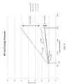
- FIG. 4 represents an exemplary reference graph having parameter values and data received by parameter signal process unit 208 when the parameter values and data are provided by faultless sensors, such as ISP 48 and CHP 50, in response to CBV 30 moving between an opened position and a closed position.
- a first line segment 402 indicates a faultless CHP 50 having a beginning pressure value of approximately 100 kilopascal (kPa) at 600 RPM and an ending pressure value of approximately 118 kPa at 2000 RPM, when CBV 30 is in the opened position.
- a second line segment 404 indicates a faultless ISP 48 having a beginning pressure value of approximately 102 kPa at 600 RPM and an ending pressure value of approximately 119 kPa, when CBV 30 is in the opened position.
- a third line segment 406 indicates a faultless CHP 50 having a beginning pressure value of approximately 102 kPa at 600 RPM and an ending pressure value of 122 kPa at 2000 RPM, when CBV 30 is in the closed position.
- a fourth line segment 408 indicates a faultless ISP 48 having a beginning pressure value of approximately 103 kPa and an ending pressure value of approximately 181 kPa, when CBV 30 is in the closed position.
- At least one of a turbo speed sensor in-range failure mode, an inter-stage pressure sensor failure mode, a charge pressure sensor in-range failure mode, a high speed turbo failure mode, or a compressor by-pass valve efficiency failure mode can be isolated based on detection of a deviation from the pressure values shown in FIG. 4 , indicating a faulty engine component.
- failure mode isolation unit 206 monitors data signals, such as parameter values and data provided by sensors 212 (e.g., corresponding to CUP 50 and/or ISP 48) and determines if the charge pressure value exceeds a predetermined threshold charge pressure during a predetermined time period between when CBV 30 is in the opened position at the second engine speed and when CBV 30 is in the closed position at the second engine speed.
- pressure values for ISP 48 and CHP 50 should be nearly identical (e.g., line segments 402 and 404) between 600 RPM and 2000 RPM when CBV 30 is opened. However, if the pressure value of CUP 50 is greater than the one of ISP 48 by 7 kPa, a possible CBV stuck or partially stuck closed condition is suspected.
- Failure mode isolation unit 206 is further configured to perform two checks.
- First check is to monitor data signals corresponding to the charge pressure sensor and determine if the charge pressure exceeded a predetermined threshold charge pressure during a time period between when CBV 30 is in the opened position at the second engine speed and when CBV 30 is in the closed position at the second engine speed.
- Second check is to monitor data signals corresponding to the turbo speed sensor and determine if the turbo speed is within a predetermined turbo speed range when CBV 30 is in the closed position at the second engine speed. Based on a condition whether at least one of first and second checks passes or fails, one of three different actions described below is performed.
- first action refers to if both first and second check pass, and there is a pre-existing fault code, then inter-stage pressure sensor 48 is the possible failed part. A service technician is guided to check inter-stage pressure sensor 48, and replace it as needed. Road testing is required to validate the replacement fixes the problem and no fault codes turn on.
- Second action refers to if first check passes and second check fails, then turbo speed sensor 46 is the failed part. The service technician is guided to check turbo speed sensor 46 and replace it as needed. The failure mode isolation unit test is repeated.
- Third action refers to if first check fails, then second check does not matter. In this case, there are three possible failed parts, charge pressure sensor 50, compressor by-pass valve 30 or high pressure turbo. For example, the service technician is guided to replace charge pressure sensor 50 and repeat the failure mode isolation unit test. If first check fails again after replacing the charge pressure sensor, then compressor bypass valve 50 or high pressure turbo needs to be inspected and replaced it as needed.
- FIG. 5 shows a second example of isolating the failure modes related to TSPD 46.
- parameter signal process unit 208 receives data provided by TSPD 46 in response to CBV 30 being moved to an opened position.
- parameter signal process unit 208 receives data provided by TSPD 46 in response to CBV 30 being moved to a closed position.
- control signal generation unit 204 increases an engine speed from a first engine speed (e.g., 600 RPM) to a second engine speed (e.g., 2000 RPM).
- parameter signal process unit 208 receives data (e.g., turbo speed) provided by TSPD 46 when the engine speed is at 600 RPM and CBV 30 is in the opened position, and receives data provided by TSPD 46 when the engine speed is at 600 RPM and CBV 30 is in the closed position.
- parameter signal process unit 208 receives data provided by TSPD 46 when the engine speed is at 2000 RPM and CBV 30 is in the opened position, and receives data provided by TSPD 46 when the engine speed is at 2000 RPM and CBV 30 is in the closed position.
- FIG. 5 represents an exemplary reference graph having parameter values and data received by parameter signal process unit 208 when the parameter values and data are provided by faultless sensors, such as TSPD 46, in response to CBV 30 moving between an opened position and a closed position.
- a first line segment 502 indicates a faultless TSPD 46 having a beginning turbo speed of approximately 32 kiloRPM (kRPM) at 600 RPM engine speed and an ending turbo speed of approximately 112 kRPM at 2000 RPM engine speed, when CBV 30 is in the opened position.
- a second line segment 504 indicates a faultless TSPD 46 having a beginning turbo speed of approximately 33 kRPM at 600 RPM engine speed and an ending turbo speed of approximately 148 kRPM, when CBV 30 is in the closed position.
- a turbo speed sensor in-range failure mode can be isolated based on a deviation from the turbo speeds shown in FIG. 5 , indicating a faulty engine component.
- failure mode isolation unit 206 monitors data signals, such as parameter values and data provided by sensors 212 (e.g., corresponding to TSPD 46) and determines if the turbo speed is within a predetermined turbo speed range when CBV 30 is in the closed position at the second engine speed. When no deviation is detected based on values shown in FIGS.
- TSPD 46, ISP 48, and CHP 50 are presumed operating appropriately, and thus a faulty CBV 30 is suspected.
- the compressor by-pass valve efficiency failure mode is isolated by failure mode isolation unit 206.
- CUP 50 and TSPD 46 are both above the predetermined levels when CBV 30 is closed at the second engine speed of 2000 RPM, and a fault code exists, then inter-stage pressure sensor 46 is faulty. If CUP 50 is above the predetermined level and TSPD 46 is not above the predetermined level when CBV 30 is closed at the second engine speed of 2000 RPM, then turbo speed sensor 46 is faulty. If CUP 50 is not above the predetermined levels with CBV 30 closed at the second engine speed of 2000 RPM, then CUP 50, CBV 30 or high power turbo could be faulty. Failure mode isolation unit 206 then instructs the service technician to replace CHP 50 and repeat the failure mode isolation unit 206 test. If CHP 50 is still not above the predetermined levels with CBV 30 closed at the second engine speed of 2000 RPM, then failure is isolated to either CBV or high pressure (HP) turbo.
- HP high pressure
- the term "unit” refers to, be part of, or include an Application Specific Integrated Circuit (ASIC), an electronic circuit, a processor or microprocessor (shared, dedicated, or group) and/or memory (shared, dedicated, or group) that executes one or more software or firmware programs, a combinational logic circuit, and/or other suitable components that provide the described functionality.
- ASIC Application Specific Integrated Circuit
- processor or microprocessor shared, dedicated, or group
- memory shared, dedicated, or group
- each sub-unit can be operated as a separate unit from ECU 42, and other suitable combinations of sub-units are contemplated to suit different applications.
- the units 202-210 are illustratively depicted as separate units, the functions and capabilities of each unit can be implemented, combined, and used in conjunction with/into any unit or any combination of units to suit different applications.
- the sub-units 206 and 208 are disposed on an external server or another suitable computing device, such as a laptop or a mobile device, to facilitate easy mobility of the present system.
- the sub-units 206 and 208 are separated from the parent unit 52, and independently executed by the server or computing device.
- Other suitable combinations of the sub-units 202-210 are also contemplated depending on different applications.
Landscapes
- Engineering & Computer Science (AREA)
- Chemical & Material Sciences (AREA)
- Physics & Mathematics (AREA)
- General Physics & Mathematics (AREA)
- Combustion & Propulsion (AREA)
- Mechanical Engineering (AREA)
- General Engineering & Computer Science (AREA)
- Automation & Control Theory (AREA)
- Chemical Kinetics & Catalysis (AREA)
- Supercharger (AREA)
- Combined Controls Of Internal Combustion Engines (AREA)
- Output Control And Ontrol Of Special Type Engine (AREA)
- Control Of Turbines (AREA)
Description
- The present disclosure generally relates to diagnostic systems for internal combustion engines, and more specifically to a fault isolation test that includes controlling the engine in a unique manner during a service event to allow for identification of one or more failed components of an internal combustion engine.
- Systems for diagnosing engine components based strictly on the behavior of such components are known and have been implemented extensively in the automotive and diesel engine industries. However, with such conventional diagnostic approaches, it is difficult to diagnose some fault conditions associated with electrically actuatable control mechanisms.
- For example, a control system coupled to an internal combustion engine includes a control mechanism having an actuator responsive to an actuator command to control the mechanism to a specified position, and a position sensor producing a signal indicative of a position of the mechanism relative to a reference position. Using conventional diagnostic techniques, the sensor signal is typically analyzed to determine the overall operability of the mechanism and/or to determine fault conditions associated with the sensor itself. However, fault conditions and/or failure modes may occur with respect to the actuator and/or the mechanism itself that are undetectable via analysis of the sensor signal alone. As one specific example, the signal produced by a control valve position sensor may indicate that the valve is moving and operating normally even though a failure condition exists that prevents the valve from forming a proper seal with a valve-sealing surface.
- Accordingly, it is desirable to develop a component diagnostic system that includes a fault isolation methodology that allows for the identification of a failed component or a particular failure mode based on one or more fault codes generated by the control unit of an internal combustion engine.
DE 10 2015 120977 A1 ,EP 2 489 850 A1 ,US 2007/288134 A1 andDE 10 2004 036064 A1 disclose the distinction between sensor and actuator failures in specific engine components. - In one embodiment of the present disclosure, a method includes the features according to claim 1. Further embodiments of the method are disclosed by dependent claims 2 to 7.
- In another embodiment of the present disclosure, a system includes the features according to claim 8. Further embodiments of the system are disclosed by dependent claims 9 to 15.
- The above-mentioned and other features of this disclosure and the manner of obtaining them will become more apparent and the disclosure itself will be better understood by reference to the following description of embodiments of the present disclosure taken in conjunction with the accompanying drawings, wherein:
-
FIG. 1 is a schematic illustration of an exemplary internal combustion engine system having a diagnostic unit in accordance with embodiments of the present disclosure; -
FIG. 2 is a functional block diagram of the diagnostic unit ofFIG. 1 featuring related units and components associated with the diagnostic unit in accordance with embodiments of the present disclosure; -
FIG. 3 is a flowchart illustrating one example of a method of isolating failure modes of a vehicle in accordance with embodiments of the present disclosure; -
FIG. 4 is a graphical representation of one example of the method of isolating the failure modes related to an inter-stage pressure sensor and a charge pressure sensor in accordance with embodiments of the present disclosure; and -
FIG. 5 is a graphical representation of another example of the method of isolating the failure modes related to a turbo speed sensor in accordance with embodiments of the present disclosure. - While the present disclosure is amenable to various modifications and alternative forms, specific embodiments have been shown by way of example in the drawings and are described in detail below. The intention, however, is not to limit the present disclosure to the particular embodiments described. On the contrary, the present disclosure is intended to cover all modifications, equivalents, and alternatives falling within the scope of the present disclosure as defined by the appended claims.
- In the following detailed description, reference is made to the accompanying drawings which form a part hereof, and in which is shown by way of illustration specific embodiments in which the present disclosure is practiced. These embodiments are described in sufficient detail to enable those skilled in the art to practice the present disclosure, and it is to be understood that other embodiments can be utilized and that structural changes can be made without departing from the scope of the present disclosure. Therefore, the following detailed description is not to be taken in a limiting sense, and the scope of the present disclosure is defined by the appended claims.
- In one embodiment, a present system includes a controller having a control signal generation unit that provides control signals to actuate one or more valve actuators of an engine to a desired position, and control signals to modify one or more operational parameters and an operational mode of the engine. The present system and individual component diagnostic units are dependent on at least one engine sensors and/or actuator position sensor. To differentiate between the component error and the dependent sensor/actuator error, the present system generates at least one fault code corresponding to one or more failure modes. In some embodiments, all the possible failure modes are then manually checked by a service technician to correctly diagnose the failure mode. For example, a failure mode isolation unit can be used by the service technician to isolate the failure mode from the one or more failure modes in response to modifying the operational parameters or the operational mode, causing actuation of the valves to a desired position, and receiving and processing the parameter signals from the sensors.
-
FIG. 1 shows an exemplary internalcombustion engine system 10 of a vehicle including anengine 12, afueling system 14 including afuel mixer 16 to mix air with fuel and/or with a recirculated air/fuel mixture, and acharging subsystem 18 including a low pressure (LP)turbocharger 20 and a high pressure (HP)turbocharger 22, eachturbocharger inter-air cooler 24 is positioned between HPturbocharger 22 andLP turbocharger 20 to cool the densified air/fuel mixture output fromLP turbocharger 20. A charged-air cooler (CAC) 26 is provided downstream of and to cool the densified air/fuel mixture output from HPturbocharger 22. The densified air/fuel mixture discharged throughCAC 26 is supplied to a compressor bypass valve (CBV) 30 which is operable in accordance with a bypass signal provided by acontroller 32 to direct the densified air/fuel mixture, or any portion thereof, to a fuel metering assembly orthrottle 34, or back tofuel mixer system 16 for mixing with fresh air and fuel. As used herein, "gas charge" refers to gases supplied tofuel metering assembly 34.Engine 12 includesintake manifold 36 receiving the gas charge fromCBV 30,cylinders 38 to combust the gas charge, andexhaust manifold 40 receiving combustion gases fromcylinders 38 and supplying the combusted gases to two-stage charging subsystem 18. - In
FIG. 1 ,controller 32 includes an engine control unit (ECU) 42 operable to produce control signals on any one or more ofsignal paths 44 to control the operation of one or more corresponding suitably positioned engine components, such asfueling system 14,CBV 30, andcharging subsystem 18. One or more air handling system components described above are controlled by ECU 42 for regulating operation ofengine system 10. ECU 42 is in communication with a controller area network (CAN) or other serial bus systems for communicating with various components and sensors onengine 12 and/or within the vehicle. For example, a turbo speed sensor (TSPD) 46, an inter-stage pressure sensor (ISP) 48, and a charge pressure sensor (CHP) 50 are used to determine performance ofcharging subsystem 18. In this example, TSPD 46 monitors a turbo spinning speed ofcharging subsystem 18,ISP 48 monitors a ratio of an inter-stage air pressure betweenLP turbocharger 20 and HPturbocharger 22, and CHP 50 monitors a manifold turbo pressure ofcharging subsystem 18. Other air handling system components, such as an exhaust gas recirculation (EGR) valve, a variable geometry turbocharger turbine, an exhaust throttle, and/or a wastegate, and the like, are also controlled by ECU 42. - ECU 42 includes a
diagnostic unit 52 configured for detecting a fault of an engine component based on at least one fault code corresponding to one or more failure modes by isolating a failure mode from the one or more failure modes. In one example,diagnostic unit 52 performs diagnostic steps to isolate faults/failures associated with any one or more of the air handling system components just described, as a function of a corresponding commanded actuator position and resulting actuator position, and further as a function of another engine/air handling system operating condition other than the resulting actuator position. Such a strategy allows for discrimination of the source of a detected fault/failure as between the actuator position sensor, the actuator, and the air handling system itself. Advantageously, the isolated failure mode prevents incorrect replacement of components in a service event, and misidentification of failed components for a proper initial repair. As such, only components identified by the isolated failure mode are replaced or serviced, thereby reducing maintenance time and expenses. -
FIG. 2 shows an exemplarydiagnostic unit 52 featuring its sub-units in accordance with embodiments of the present disclosure. In this example,diagnostic unit 52 includes aninitialization unit 202, a controlsignal generation unit 204, afailure detection unit 205, a failuremode isolation unit 206, a parametersignal process unit 208, and adisplay unit 210.Initialization unit 202 receives signals fromsensors 212 via hardware input/output (HWIO)devices 214. In one example, HWIOdevices 214 include aninterface control unit 216 and hardware interfaces/drivers 218.Interface control unit 216 provides an interface between the units 202-210, and hardware interfaces/drivers 218. Hardware interfaces/drivers 218 control operation of, for example, a camshaft phaser position sensor, a pressure sensor, an engine speed sensor, and other engine system components. Other engine system devices include ignition coils, spark plugs, throttle valves, solenoids, etc. Hardware interface/drivers 218 also receive sensor signals, which are communicated to the control unit, such ascontroller 32.Memory 220 is operatively coupled toHWIO devices 214 to store and retrieve operational data and parameters.Memory 220 can be part of ECU 42 or separate from ECU 42. - As another example,
interface control unit 216 is communicably coupled tocontroller 32, and provides commands to controller 32 corresponding to a desired position of one or more valves, provides commands to controller 32 wherein at least one of the commands causescontroller 32 to modify at least one of: an operational parameter ofengine 12 and a mode of operation ofengine 12, and receives one or more parameter signals corresponding to an operational parameter ofengine 12.Interface control unit 216 includes failuremode isolation unit 206 which is configured to isolate a failure mode of one or more engine components from the one or more failure modes in response to actuating at least one valve, modifying the mode of operation ofengine 12, and modifying at least one operational parameter ofengine 12. Examples are described in greater detail below in paragraphs relating toFIGS. 3-5 . Other combinations with sub-units 200-210 andinterface control unit 216 are also contemplated to suit different applications. - In this example,
sensors 212 include TSPD 46,ISP 48, andCHP 50, but other suitable sensors, such as a camshaft phaser position sensor or an engine speed sensor, are contemplated to suit different applications.Initialization unit 202 generates an initialization signal based on the signals fromsensors 212 and determines whether to enable controlsignal generation unit 204 by verifying that various initialization conditions are met. For example, the initialization conditions include ensuring that the engine speed of theengine 12 is at a predetermined engine speed (e.g., 600 or 2000 RPM) and that the vehicle has been in a safe stationary position for a predetermined time period. When the initialization conditions are met,initialization unit 202 generates and transmits the initialization signal to controlsignal generation unit 204. - During operation, control
signal generation unit 204 is configured to provide control signals to one or more valve actuators, such as the bypass signal forCBV 30, ofengine 12 to actuate one or more valves associated with the actuators to a desired position. Further, controlsignal generation unit 204 is configured to provide control signals to modify one or more operational parameters ofengine 12, and to provide control signals to modify an operational mode of engine. For example, controlsignal generation unit 204 provides an engine speed control signal to modify the engine speed ofengine 12 from 600 RPM to 2000 RPM. In another example, controlsignal generation unit 204 provides an operation mode signal to modify the engine operation mode ofengine 12 from an automated operation mode to a normal operation mode. In use, controlsignal generation unit 204 provides an override signal to suppress controls related to EGR or exhaust back-pressure valve (EBV) operations. Other control signals associated withengine 12 are also contemplated to suit different applications. - Parameter
signal process unit 208 is configured to receive parameter signals corresponding to at least one operational parameter ofengine 12. For example, parametersignal process unit 208 receives parameter signals associated withengine 12, such as a gear position signal, a coolant temperature signal, a battery voltage signal, a net torque signal, an exhaust pressure signal, and the like. In one example, parametersignal process unit 208 receives the parameter signals to prepareengine 12 in a predetermined diagnostic condition (e.g., startingengine 12 in an idle state at 600 RPM). Further, parametersignal process unit 208 receives parameter signals from at least one sensor coupled toengine 12, wherein the signal corresponds, for example, to a position of a valve. In other examples, parametersignal process unit 208 receives parameter signals associated with chargingsubsystem 18, such as a charge pressure signal, a turbo speed signal, and a CBV position signal. -
Failure detection unit 205 is configured to generate at least one fault code corresponding to one or more failure modes, wherein the fault code indicates a potential failure of one or more engine components. In some embodiments,failure detection unit 205 is further configured to detect a failure corresponding to one or more failure modes and generate a fault code, while failuremode isolation unit 206 is configured to isolate the failure to one or more failed parts. The one or more engine components include: a turbo speed sensor, an inter-stage pressure sensor, a charge pressure sensor, and a compressor by-pass valve position sensor, and the one or more failure modes include: a turbo speed sensor in-range failure mode, an inter-stage pressure sensor failure mode, a charge pressure sensor in-range failure mode, a high speed turbo failure mode, and a compressor by-pass valve efficiency failure mode. - For example, in an air handling system, a first fault code having a numerical value of 686 indicates a turbo speed fault, a second fault code having a numerical value of 2973 indicates a charge pressure fault, a third fault code having a numerical value of 4683 indicates a CBV stuck open fault, and a fourth fault code having a numerical value of 4684 indicates a CBV stuck closed fault. In this example, these fault codes are related to one or more failure modes of
engine 12, namely a turbo speed sensor in-range failure mode, an inter-stage pressure sensor in-rage failure mode, a charge pressure sensor in-range failure mode, and a CBV/high speed turbo efficiency failure mode. Conventionally, it is difficult to determine which failure mode is related to which fault code. However, as described further below, failuremode isolation unit 206 isolates afailure mode 222 from the one or more failure modes in response to at least one of: modifying one or more operational parameters ofengine 12, modifying an operational mode ofengine 12, causing actuation of one or more valves to a desired position, and receiving parameter signals corresponding to at least one of an operational parameter ofengine 12 and a sensor (e.g.,TSPD 46,ISP 48, and CHP 50) coupled toengine 12. -
Display unit 210 is configured to output theisolated failure mode 222 for display, e.g., on adisplay device 224. For example, theisolated failure mode 222 is presented on a screen or printed on a paper for viewing in real-time, wherein the data related to theisolated failure mode 222 corresponds to the operational parameters ofengine 12. Other suitable presentation methods are contemplated to suit the application. -
FIG. 3 shows an exemplary method of isolating a failure mode from one or more failure modes of a vehicle in accordance with embodiments of the present disclosure. It will be described with reference toFIGS. 1 and2 . It should be understood that the blocks within the method can be modified and executed in a different order or sequence without altering the principles of the present disclosure. - In operation, at
block 302,failure detection unit 205 generates at least one fault code corresponding to one or more failure modes. Exemplary fault codes include a turbo speed fault code, a charge pressure fault code, a compressor by-pass valve stuck open fault code, or a compressor by-pass valve stuck closed fault code. Exemplary failure modes include a turbo speed sensor in-range failure mode, an inter-stage pressure sensor failure mode, a charge pressure sensor in-range failure mode, a high speed turbo failure mode, or a compressor by-pass valve efficiency failure mode. As described above, when one or more of the fault codes 686, 2973, 4683, 4684 are generated byfailure detection unit 205 during a diagnostic event, at least one of failure modes is related to the fault codes to indicate a potential failure of one or more engine components. In this example, the fault codes 686, 2973, 4683, and 4684 indicate the failure of the air handling system in one ofsensors TSPD 46,ISP 48, andCHP 50, orCBV 30. - At
block 304, failuremode isolation unit 206 modifies a mode of operation ofengine 12 in response to the generated at least one fault code. Modifying the engine operation mode refers to operatingengine 12 in a normal mode and then operatingengine 12 in an abnormal mode. The normal mode refers to a normal driving condition where none of the operational parameters ofengine 12 is overridden. The abnormal mode refers to an abnormal driving condition where at least one operational parameter ofengine 12 is overridden for testing. For example, failuremode isolation unit 206places engine 12 in a normal operation mode at an engine speed of 600 RPM without performing EGR or EBV operations such thatengine 12 is placed in a condition for setting up a specific exhaust flow path with no EGR flow. As another example, failuremode isolation unit 206places engine 12 in an abnormal operation mode by overriding the at least one operational parameter associated with one or more valve actuators or by modifying an engine speed ofengine 12. In the abnormal operation mode, the operating parameters include values exhibiting an out-of-range characteristic of normal driving conditions (e.g., an out-of-mission mode). For example, in the abnormal operation mode, the testing is conducted only in a stationary, non-driving condition of the vehicle. Atblock 306, failuremode isolation unit 206 commands the controlsignal generation unit 204 to actuate one or more valve actuators ofengine 12 to a desired position in response to the generated at least one of fault code. For example, controlsignal generation unit 204 generates a control signal to overrideCBV 30 to be fully opened to bypass the compressor and receive an intake air flow. - At
block 308, parametersignal process unit 208 receives at least one parameter value corresponding to one or more operational parameters ofengine 12 in response to the generated at least one of fault code. For example, parametersignal process unit 208 receives parameter values, such as RPMs, sensor pressures and actuator position in response to the generated fault codes 686, 2973, 4683, 4684. Atblock 310, parametersignal process unit 208 receives data provided by at least one sensor positioned withinengine 12 in response to the generated at least one of fault code. For example, parametersignal process unit 208 receives a turbo speed fromTSPD 46, or pressure values fromISP 48 andCHP 50 when one or more of the fault codes 686, 2973, 4683, 4684 are generated. - At
block 312, failuremode isolation unit 206 isolates a failure mode from the one or more failure modes in response to at least one of: modifying the mode of operation ofengine 12, actuating one or more valve actuators, such asCBV 30, receiving the at least one parameter value, and receiving the data provided by at least one sensor, such asTSPD 46,ISP 48, andCHP 50. During the diagnostic event, at least one operational parameter ofengine 12 is modified in response to the generated at least one fault code. In this example,engine 12 is an internal combustion engine, an engine speed is modified by controlsignal generation unit 204 from 600 RPM to 2000 RPM, and failuremode isolation unit 206 compares one or more changes in the turbo speed and pressure values at two different engine speeds (e.g., 600 and 2000 RPMs) to detect the potential failure of one or more engine components. Exemplary isolation techniques are illustrated in paragraphs below relating toFIGS. 4 and5 . -
FIG. 4 shows a first example of isolating the failure modes related toISP 48 and/orCHP 50. InFIG. 4 , parametersignal process unit 208 receives data provided byISP 48 and/orCHP 50 in response toCBV 30 being moved to an opened position. Similarly, parametersignal process unit 208 receives data provided byISP 48 and/orCHP 50 in response toCBV 30 being moved to a closed position. In this example, controlsignal generation unit 204 increases an engine speed from a first engine speed (e.g., 600 RPM) to a second engine speed (e.g., 2000 RPM). As discussed above,sensors 212 include a turbo speed sensor (TSPD) 46, an inter-stage pressure sensor (ISP) 48, and a charge pressure sensor (CHP) 50. - In
FIG. 4 , parametersignal process unit 208 receives data (e.g., pressure) provided byISP 48 and/orCHP 50 when the engine speed is at 600 RPM andCBV 30 is in the opened position, and receives data provided byISP 48 and/orCHP 50 when the engine speed is at 600 RPM andCBV 30 is in the closed position. Similarly, parametersignal process unit 208 receives data provided byISP 48 and/orCHP 50 when the engine speed is at 2000 RPM andCBV 30 is in the opened position, and receives data provided byISP 48 and/orCHP 50 when the engine speed is at 2000 RPM andCBV 30 is in the closed position.FIG. 4 represents an exemplary reference graph having parameter values and data received by parametersignal process unit 208 when the parameter values and data are provided by faultless sensors, such asISP 48 andCHP 50, in response toCBV 30 moving between an opened position and a closed position. - In this example, a
first line segment 402 indicates afaultless CHP 50 having a beginning pressure value of approximately 100 kilopascal (kPa) at 600 RPM and an ending pressure value of approximately 118 kPa at 2000 RPM, whenCBV 30 is in the opened position. Asecond line segment 404 indicates afaultless ISP 48 having a beginning pressure value of approximately 102 kPa at 600 RPM and an ending pressure value of approximately 119 kPa, whenCBV 30 is in the opened position. A third line segment 406 indicates afaultless CHP 50 having a beginning pressure value of approximately 102 kPa at 600 RPM and an ending pressure value of 122 kPa at 2000 RPM, whenCBV 30 is in the closed position. Afourth line segment 408 indicates afaultless ISP 48 having a beginning pressure value of approximately 103 kPa and an ending pressure value of approximately 181 kPa, whenCBV 30 is in the closed position. - At least one of a turbo speed sensor in-range failure mode, an inter-stage pressure sensor failure mode, a charge pressure sensor in-range failure mode, a high speed turbo failure mode, or a compressor by-pass valve efficiency failure mode can be isolated based on detection of a deviation from the pressure values shown in
FIG. 4 , indicating a faulty engine component. For example, failuremode isolation unit 206 monitors data signals, such as parameter values and data provided by sensors 212 (e.g., corresponding toCUP 50 and/or ISP 48) and determines if the charge pressure value exceeds a predetermined threshold charge pressure during a predetermined time period between whenCBV 30 is in the opened position at the second engine speed and whenCBV 30 is in the closed position at the second engine speed. In this example, pressure values forISP 48 andCHP 50 should be nearly identical (e.g.,line segments 402 and 404) between 600 RPM and 2000 RPM whenCBV 30 is opened. However, if the pressure value ofCUP 50 is greater than the one ofISP 48 by 7 kPa, a possible CBV stuck or partially stuck closed condition is suspected. - Failure
mode isolation unit 206 is further configured to perform two checks. First check is to monitor data signals corresponding to the charge pressure sensor and determine if the charge pressure exceeded a predetermined threshold charge pressure during a time period between whenCBV 30 is in the opened position at the second engine speed and whenCBV 30 is in the closed position at the second engine speed. Second check is to monitor data signals corresponding to the turbo speed sensor and determine if the turbo speed is within a predetermined turbo speed range whenCBV 30 is in the closed position at the second engine speed. Based on a condition whether at least one of first and second checks passes or fails, one of three different actions described below is performed. - As an example only, first action refers to if both first and second check pass, and there is a pre-existing fault code, then inter-stage
pressure sensor 48 is the possible failed part. A service technician is guided to checkinter-stage pressure sensor 48, and replace it as needed. Road testing is required to validate the replacement fixes the problem and no fault codes turn on. Second action refers to if first check passes and second check fails, thenturbo speed sensor 46 is the failed part. The service technician is guided to checkturbo speed sensor 46 and replace it as needed. The failure mode isolation unit test is repeated. Third action refers to if first check fails, then second check does not matter. In this case, there are three possible failed parts,charge pressure sensor 50, compressor by-pass valve 30 or high pressure turbo. For example, the service technician is guided to replacecharge pressure sensor 50 and repeat the failure mode isolation unit test. If first check fails again after replacing the charge pressure sensor, thencompressor bypass valve 50 or high pressure turbo needs to be inspected and replaced it as needed. -
FIG. 5 shows a second example of isolating the failure modes related to TSPD 46. InFIG. 5 , parametersignal process unit 208 receives data provided byTSPD 46 in response toCBV 30 being moved to an opened position. Similarly, parametersignal process unit 208 receives data provided byTSPD 46 in response toCBV 30 being moved to a closed position. As similarly shown inFIG. 4 , controlsignal generation unit 204 increases an engine speed from a first engine speed (e.g., 600 RPM) to a second engine speed (e.g., 2000 RPM). - In
FIG. 5 , parametersignal process unit 208 receives data (e.g., turbo speed) provided byTSPD 46 when the engine speed is at 600 RPM andCBV 30 is in the opened position, and receives data provided byTSPD 46 when the engine speed is at 600 RPM andCBV 30 is in the closed position. Similarly, parametersignal process unit 208 receives data provided byTSPD 46 when the engine speed is at 2000 RPM andCBV 30 is in the opened position, and receives data provided byTSPD 46 when the engine speed is at 2000 RPM andCBV 30 is in the closed position.FIG. 5 represents an exemplary reference graph having parameter values and data received by parametersignal process unit 208 when the parameter values and data are provided by faultless sensors, such asTSPD 46, in response toCBV 30 moving between an opened position and a closed position. - In this example, a first line segment 502 indicates a
faultless TSPD 46 having a beginning turbo speed of approximately 32 kiloRPM (kRPM) at 600 RPM engine speed and an ending turbo speed of approximately 112 kRPM at 2000 RPM engine speed, whenCBV 30 is in the opened position. Asecond line segment 504 indicates afaultless TSPD 46 having a beginning turbo speed of approximately 33 kRPM at 600 RPM engine speed and an ending turbo speed of approximately 148 kRPM, whenCBV 30 is in the closed position. - Again, at least one of a turbo speed sensor in-range failure mode, an inter-stage pressure sensor failure mode, a charge pressure sensor in-range failure mode, a high speed turbo failure mode, or a compressor by-pass valve efficiency failure mode can be isolated based on a deviation from the turbo speeds shown in
FIG. 5 , indicating a faulty engine component. For example, failuremode isolation unit 206 monitors data signals, such as parameter values and data provided by sensors 212 (e.g., corresponding to TSPD 46) and determines if the turbo speed is within a predetermined turbo speed range whenCBV 30 is in the closed position at the second engine speed. When no deviation is detected based on values shown inFIGS. 4 and5 ,TSPD 46,ISP 48, andCHP 50 are presumed operating appropriately, and thus afaulty CBV 30 is suspected. As a result, in this example, the compressor by-pass valve efficiency failure mode is isolated by failuremode isolation unit 206. - As an example only, if
CUP 50 andTSPD 46 are both above the predetermined levels whenCBV 30 is closed at the second engine speed of 2000 RPM, and a fault code exists, then inter-stagepressure sensor 46 is faulty. IfCUP 50 is above the predetermined level andTSPD 46 is not above the predetermined level whenCBV 30 is closed at the second engine speed of 2000 RPM, thenturbo speed sensor 46 is faulty. IfCUP 50 is not above the predetermined levels withCBV 30 closed at the second engine speed of 2000 RPM, thenCUP 50,CBV 30 or high power turbo could be faulty. Failuremode isolation unit 206 then instructs the service technician to replaceCHP 50 and repeat the failuremode isolation unit 206 test. IfCHP 50 is still not above the predetermined levels withCBV 30 closed at the second engine speed of 2000 RPM, then failure is isolated to either CBV or high pressure (HP) turbo. - Embodiments of the present disclosure are described below by way of example only, with reference to the accompanying drawings. Further, the following description is merely exemplary in nature and is in no way intended to limit the disclosure, its application, or uses. As used herein, the term "unit" refers to, be part of, or include an Application Specific Integrated Circuit (ASIC), an electronic circuit, a processor or microprocessor (shared, dedicated, or group) and/or memory (shared, dedicated, or group) that executes one or more software or firmware programs, a combinational logic circuit, and/or other suitable components that provide the described functionality. Thus, while this disclosure includes particular examples and arrangements of the units, the scope of the present system should not be so limited since other modifications will become apparent to the skilled practitioner.
- Furthermore, while the above description describes hardware in the form of a processor executing code, hardware in the form of a state machine, or dedicated logic capable of producing the same effect, other structures are also contemplated. Although the sub-units 202-210 are illustrated as children units subordinate of the
parent unit 52, each sub-unit can be operated as a separate unit from ECU 42, and other suitable combinations of sub-units are contemplated to suit different applications. Also, although the units 202-210 are illustratively depicted as separate units, the functions and capabilities of each unit can be implemented, combined, and used in conjunction with/into any unit or any combination of units to suit different applications. For example, in some embodiments, the sub-units 206 and 208 are disposed on an external server or another suitable computing device, such as a laptop or a mobile device, to facilitate easy mobility of the present system. In this configuration, the sub-units 206 and 208 are separated from theparent unit 52, and independently executed by the server or computing device. Other suitable combinations of the sub-units 202-210 are also contemplated depending on different applications. - It is to be understood that the above description is intended to be illustrative, and not restrictive. Many other embodiments will be apparent to those of skill in the art upon reading and understanding the above description. For example, it is contemplated that features described in association with one embodiment are optionally employed in addition or as an alternative to features described in associate with another embodiment. The scope of the present disclosure should, therefore, be determined with reference to the appended claims.
Claims (15)
- A method comprising:generating (302), by a controller (32), at least one fault code corresponding to one or more failure modes;in response to the generated at least one fault code:modifying (304), by the controller, a mode of operation of an engine (12) by operating the engine in a normal mode and then operating the engine in a testing mode;controlling (306), by the controller, one or more valve actuators of the engine by actuating the one or more valve actuators to a desired position;receiving (308), by the controller, at least one parameter value corresponding to one or more operational parameters of the engine to determine whether the at least one parameter value is within a predetermined value range;receiving (310), by the controller, data provided by at least one sensor (212) positioned within the engine to determine whether the data is within a predetermined data range; andisolating (312), by the controller, a failure mode from the one or more failure modes based on at least one of: modifying the mode of operation by operating the engine in the normal mode and then operating the engine in the testing mode, controlling the one or more valve actuators by actuating the one or more valve actuators to the desired position, receiving the at least one parameter value corresponding to the one or more operational parameters to determine whether the at least one parameter value is within the predetermined value range, and receiving the data provided by the at least one sensor to determine whether the data is within the predetermined data range.
- The method of claim 1, wherein:the at least one fault code includes a turbo speed fault code, a charge pressure fault code, an inter-stage pressure fault code, a compressor by-pass valve stuck open fault code, and a compressor by-pass valve stuck closed fault code;the one or more failure modes include a turbo speed sensor in-range failure mode, an inter-stage pressure sensor failure mode, a charge pressure sensor in-range failure mode, a high speed turbo failure mode, a high pressure turbo failure mode, and a compressor by-pass valve efficiency failure mode;operating the engine in the normal mode includes operating the engine in a normal driving condition; andoperating the engine in the testing mode includes operating the engine in a stationary non-driving condition.
- The method of any of the previous claims, wherein the engine is an internal combustion engine and in response to the generated at least one fault code:
modifying, by the controller, at least one of the one or more operational parameters of the engine by modifying an engine speed of the internal combustion engine. - The method of any of the previous claims, wherein receiving the data provided by the at least one sensor includes receiving the data in response to a compressor by-pass valve (CBV) being moved to an opened position, and receiving the data in response to the CBV being moved to a closed position.
- The method of claim 3, wherein modifying the engine speed includes increasing the engine speed from a first engine speed to a second engine speed.
- The method of claim 5, wherein receiving the data provided by the at least one sensor includes:receiving the data when the engine speed is at the first engine speed and a compressor by-pass valve (CBV) is in an opened position, and receiving the data when the engine speed is at the first engine speed and the CBV is in a closed position; andreceiving the data when the engine speed is at the second engine speed and the CBV is in the opened position, and receiving the data when the engine speed is at the second speed and the CBV is in the closed position.
- The method of claim 6, wherein:the at least one sensor includes a turbo speed sensor (46), an inter-stage pressure sensor (48), and a charge pressure sensor (50); andthe first engine speed is 600 RPM and the second engine speed is 2000 RPM.
- A system comprising:
a controller (32) configured to:generate at least one fault code corresponding to one or more failure modes; andin response to the generated at least one fault code:modify a mode of operation of an engine (12) by providing control signals to operate the engine in a normal mode and then operate the engine in a testing mode;control one or more valve actuators of the engine by providing control signals to actuate the one or more valve actuators to a desired position;receive a parameter value corresponding to at least one operational parameter of the engine to determine whether the parameter value is within a predetermined value range;receive data from at least one sensor (212) coupled to the engine to determine whether the data is within a predetermined data range; andisolate a failure mode from the one or more failure modes based on at least one of: modifying the mode of operation by providing the control signals to operate the engine in the normal mode and then operate the engine in the testing mode, controlling the one or more valve actuators by providing the control signals to actuate the one or more valve actuators to the desired position, receiving the parameter value corresponding to the at least one operational parameter to determine whether the parameter value is within the predetermined value range, and receiving the data from the at least one sensor to determine whether the data is within the predetermined data range. - The system of claim 8, wherein:the at least one fault code indicates a potential failure of one or more engine components;the one or more engine components include a turbo speed sensor (46), an inter-stage pressure sensor (48), a charge pressure sensor (50), and a compressor by-pass valve position sensor; andthe one or more failure modes include a turbo speed sensor in-range failure mode, an inter-stage pressure sensor failure mode, a charge pressure sensor in-range failure mode, a high speed turbo failure mode, and a compressor by-pass valve efficiency failure mode.
- The system of claim 8 or 9, wherein the engine includes a compressor by-pass valve (CBV) moveable between an opened position and a closed position, and the controller is further configured to:
receive the data from the at least one sensor in response to the CBV moving to the opened position, and receive the data from the at least one sensor in response to the CBV moving to the closed position. - The system of claim 10, wherein in response to the generated at least one fault code, the controller is further configured to:modify the at least one operational parameter of the engine by providing control signals to increase an engine speed from a first engine speed to a second engine speed;receive the data from the at least one sensor when the engine speed is at the first engine speed and the CBV is in the opened position;receive the data from the at least one sensor when the engine speed is at the first engine speed and the CBV is in the closed position;receive the data from the at least one sensor when the engine speed is at the second engine speed and the CBV is in the opened position; andreceive the data from the at least one sensor when the engine speed is at the second engine speed and the CBV is in the closed position.
- The system of claim 11, wherein:the at least one sensor includes a turbo speed sensor (46), an inter-stage pressure sensor (48), and a charge pressure sensor (50); andthe first engine speed is 600 RPM and the second engine speed is 2000 RPM.
- The system of claim 12, wherein the controller is further configured to:monitor data signals corresponding to the charge pressure sensor to determine if a charge pressure exceeded a predetermined threshold charge pressure during a time period between when the CBV is in the opened position at the second engine speed and when the CBV is in the closed position at the second engine speed; andmonitor data signals corresponding to the turbo speed sensor to determine if a turbo speed is within a predetermined turbo speed range when the CBV is in the closed position at the second engine speed.
- The system of claim 8, further comprising:
an interface device communicably coupled to the controller and configured to:provide commands to the controller corresponding to the desired position of the one or more valve actuators; andprovide commands to the controller wherein at least one of the commands causes the controller to modify at least one of: the mode of operation of the engine and the at least one operational parameter of the engine. - The system of claim 14, wherein the interface device is configured to display data corresponding to the at least one operational parameter of the engine in real-time.
Applications Claiming Priority (1)
| Application Number | Priority Date | Filing Date | Title |
|---|---|---|---|
| PCT/US2017/036546 WO2018226234A1 (en) | 2017-06-08 | 2017-06-08 | Diagnostic systems and methods for isolating failure modes of a vehicle |
Publications (3)
| Publication Number | Publication Date |
|---|---|
| EP3619583A1 EP3619583A1 (en) | 2020-03-11 |
| EP3619583A4 EP3619583A4 (en) | 2020-12-09 |
| EP3619583B1 true EP3619583B1 (en) | 2023-09-06 |
Family
ID=64566764
Family Applications (1)
| Application Number | Title | Priority Date | Filing Date |
|---|---|---|---|
| EP17912733.7A Active EP3619583B1 (en) | 2017-06-08 | 2017-06-08 | Diagnostic systems and methods for isolating failure modes of a vehicle |
Country Status (4)
| Country | Link |
|---|---|
| US (1) | US11022060B2 (en) |
| EP (1) | EP3619583B1 (en) |
| CN (1) | CN111886552B (en) |
| WO (1) | WO2018226234A1 (en) |
Families Citing this family (2)
| Publication number | Priority date | Publication date | Assignee | Title |
|---|---|---|---|---|
| US11615660B2 (en) * | 2020-11-17 | 2023-03-28 | Caterpillar Inc. | Identifying a failed turbocharger of a plurality of turbochargers |
| US11887409B2 (en) | 2021-05-19 | 2024-01-30 | Pony Al Inc. | Device health code broadcasting on mixed vehicle communication networks |
Citations (1)
| Publication number | Priority date | Publication date | Assignee | Title |
|---|---|---|---|---|
| EP2489850B1 (en) * | 2011-02-21 | 2013-08-21 | Ford Global Technologies, LLC | Method for operating a turbocharger arrangement and control unit for a turbocharger arrangement |
Family Cites Families (37)
| Publication number | Priority date | Publication date | Assignee | Title |
|---|---|---|---|---|
| WO1990015316A1 (en) * | 1989-06-07 | 1990-12-13 | Electra International Pty. Ltd. | Computer-aided engine diagnostic system |
| JPH0427750A (en) * | 1990-05-22 | 1992-01-30 | Mitsubishi Electric Corp | Electronic control device for internal combustion engine |
| US6112150A (en) | 1999-04-09 | 2000-08-29 | Cummins Engine Co Inc | Fault recognition system and method for an internal combustion engine |
| AU2000272739A1 (en) | 2000-08-09 | 2002-02-18 | Abb Research Ltd | System for determining error causes |
| US6837226B2 (en) * | 2001-01-31 | 2005-01-04 | Cummins, Inc. | System for diagnosing EGR valve, actuator and sensor related failure conditions |
| US6497227B2 (en) | 2001-01-31 | 2002-12-24 | Cummins, Inc. | System for diagnosing fault conditions associated with an air handling system for an internal combustion engine |
| DE10146901A1 (en) | 2001-09-24 | 2003-05-15 | Abb Research Ltd | Method and system for processing error hypotheses |
| US6687601B2 (en) | 2002-03-21 | 2004-02-03 | Cummins, Inc. | System for diagnosing an air handling mechanism of an internal combustion engine |
| DE102004036064A1 (en) * | 2004-07-24 | 2006-03-16 | Volkswagen Ag | Diagnostic method for detecting errors in the charge pressure control of an exhaust gas turbocharger of an internal combustion engine |
| US7280941B2 (en) * | 2004-12-29 | 2007-10-09 | General Electric Company | Method and apparatus for in-situ detection and isolation of aircraft engine faults |
| US7613554B2 (en) * | 2006-06-12 | 2009-11-03 | Ford Global Technologies, Llc | System and method for demonstrating functionality of on-board diagnostics for vehicles |
| US8423226B2 (en) | 2006-06-14 | 2013-04-16 | Service Solutions U.S. Llc | Dynamic decision sequencing method and apparatus for optimizing a diagnostic test plan |
| US7631552B2 (en) | 2006-12-22 | 2009-12-15 | Detroit Diesel Corporation | Method of verifying component functionality on EGR and air systems |
| US20090043447A1 (en) * | 2007-08-07 | 2009-02-12 | General Electric Company | Systems and Methods for Model-Based Sensor Fault Detection and Isolation |
| US8036837B2 (en) * | 2008-02-29 | 2011-10-11 | Fisher Controls International Llc | Diagnostic method for detecting control valve component failure |
| US8271233B2 (en) | 2008-04-01 | 2012-09-18 | United Technologies Corporation | Method of multi-level fault isolation design |
| US7761223B2 (en) * | 2008-06-17 | 2010-07-20 | Gm Global Technology Operations, Inc. | Fuel system diagnostics by analyzing engine cylinder pressure signal and crankshaft speed signal |
| CN102209982B (en) * | 2008-09-30 | 2013-11-20 | 沙特阿拉伯石油公司 | Systems and methods for improved cooperation between control and safety systems |
| US20100082197A1 (en) * | 2008-09-30 | 2010-04-01 | Honeywell International Inc. | Intermittent fault detection and reasoning |
| JP5456699B2 (en) * | 2009-01-14 | 2014-04-02 | トヨタ自動車株式会社 | Hybrid vehicle control device and hybrid vehicle control method |
| CN101871403B (en) * | 2009-04-22 | 2014-04-02 | 通用汽车环球科技运作公司 | Diagnostic system and method for pressure sensor in driving state |
| US8648700B2 (en) | 2009-06-23 | 2014-02-11 | Bosch Automotive Service Solutions Llc | Alerts issued upon component detection failure |
| JP5280333B2 (en) * | 2009-11-06 | 2013-09-04 | 本田技研工業株式会社 | Vehicle fault diagnosis device |
| CN102050109B (en) * | 2009-11-10 | 2014-04-02 | 通用汽车环球科技运作公司 | System and method for detecting and responding to the pressure loss in hydraulic automatic transmission |
| US8498776B2 (en) | 2009-11-17 | 2013-07-30 | GM Global Technology Operations LLC | Fault diagnosis and prognosis using diagnostic trouble code markov chains |
| US20120173076A1 (en) * | 2011-01-04 | 2012-07-05 | Larry Gene Anderson | System and method for diagnosing a turbocharger |
| EP2489851B1 (en) * | 2011-02-21 | 2016-08-17 | Ford Global Technologies, LLC | Method for operating a turbocharger arrangement and control unit for a turbocharger arrangement |
| WO2013016576A1 (en) | 2011-07-26 | 2013-01-31 | United Parcel Service Of American, Inc. | Systems and methods for managing fault codes |
| EP2628918B1 (en) * | 2012-02-15 | 2020-04-22 | Ford Global Technologies, LLC | Method for operating an internal combustion engine with a turbocharger arrangement and control unit for an engine with a turbocharger arrangement |
| DE102013218576B4 (en) * | 2012-09-20 | 2023-08-24 | GM Global Technology Operations LLC (n. d. Ges. d. Staates Delaware) | Fault mode power system with multiple energy storage devices |
| US9915925B2 (en) * | 2014-02-25 | 2018-03-13 | Honeywell International Inc. | Initiated test health management system and method |
| US10030593B2 (en) * | 2014-05-29 | 2018-07-24 | Cummins Inc. | System and method for detecting air fuel ratio imbalance |
| CN104360679B (en) * | 2014-10-21 | 2017-02-08 | 南京航空航天大学 | Train suspension system fault diagnosis and fault-tolerant control method based on dynamic actuator |
| US10012137B2 (en) * | 2014-12-09 | 2018-07-03 | Ford Global Technologies, Llc | Diagnostic method for a compressor recirculation valve |
| US9879580B2 (en) | 2015-08-19 | 2018-01-30 | Cummins, Inc. | Diagnostic methods for a high efficiency exhaust aftertreatment system |
| CN106708003B (en) * | 2015-11-13 | 2019-06-28 | 湖南南车时代电动汽车股份有限公司 | A system and method for fault detection of a motor controller |
| CN105759782B (en) * | 2016-01-26 | 2018-06-08 | 中国人民解放军装甲兵工程学院 | A kind of car fault diagnosis construction of strategy method based on density of infection |
-
2017
- 2017-06-08 CN CN201780091124.7A patent/CN111886552B/en active Active
- 2017-06-08 US US16/620,200 patent/US11022060B2/en active Active
- 2017-06-08 WO PCT/US2017/036546 patent/WO2018226234A1/en not_active Ceased
- 2017-06-08 EP EP17912733.7A patent/EP3619583B1/en active Active
Patent Citations (1)
| Publication number | Priority date | Publication date | Assignee | Title |
|---|---|---|---|---|
| EP2489850B1 (en) * | 2011-02-21 | 2013-08-21 | Ford Global Technologies, LLC | Method for operating a turbocharger arrangement and control unit for a turbocharger arrangement |
Also Published As
| Publication number | Publication date |
|---|---|
| CN111886552A (en) | 2020-11-03 |
| US11022060B2 (en) | 2021-06-01 |
| US20210079865A1 (en) | 2021-03-18 |
| CN111886552B (en) | 2024-03-26 |
| EP3619583A4 (en) | 2020-12-09 |
| EP3619583A1 (en) | 2020-03-11 |
| WO2018226234A1 (en) | 2018-12-13 |
Similar Documents
| Publication | Publication Date | Title |
|---|---|---|
| US10012169B2 (en) | Method and device for diagnosing a component in a gas-routing system of an engine system having a combustion engine | |
| US6688104B2 (en) | Method and device for operating an electrical supercharger | |
| US8353198B2 (en) | Diagnostic method and device for diagnosing an intake system of an internal combustion engine | |
| US6687601B2 (en) | System for diagnosing an air handling mechanism of an internal combustion engine | |
| US8336291B2 (en) | Exhaust throttle valve diagnosing device and method | |
| US8463490B2 (en) | Method and device for diagnosing an intake tract of an internal combustion engine | |
| JP4415912B2 (en) | Engine control system | |
| KR102777552B1 (en) | Apparatus for diagnozing egr valve and method using the same | |
| JP7193017B2 (en) | LEAK DIAGNOSIS METHOD AND LEAK DIAGNOSIS DEVICE FOR BLOW-BY GAS PROCESSING DEVICE FOR INTERNAL COMBUSTION ENGINE | |
| US11215530B2 (en) | Engine health diagnosis and fault isolation with cranking test | |
| EP2952729B1 (en) | Exhaust gas recirculation control device and exhaust gas recirculation control method for an internal combustion engine | |
| EP2674597A1 (en) | Control device for internal combustion engine | |
| CN108223156B (en) | Method and apparatus for diagnosing engine systems | |
| JP2008240576A (en) | Fault diagnosis device for supercharging system | |
| JP7193016B2 (en) | LEAK DIAGNOSIS METHOD AND LEAK DIAGNOSIS DEVICE FOR BLOW-BY GAS PROCESSING DEVICE FOR INTERNAL COMBUSTION ENGINE | |
| JP5931993B2 (en) | Control device for internal combustion engine | |
| EP3619583B1 (en) | Diagnostic systems and methods for isolating failure modes of a vehicle | |
| US8234055B2 (en) | Engine movement detection systems and methods | |
| US8997559B2 (en) | Method and device for diagnosing a blowoff valve for a supercharging device of an internal combustion engine | |
| CN102656530B (en) | For implementing the method and apparatus of on board diagnosis | |
| CN107957721B (en) | Method for diagnosing a malfunction of a power stage of an electronic wastegate actuator | |
| US20180094565A1 (en) | Method and device for determining the load condition of an exhaust gas particulate filter | |
| CN108223042B (en) | Method and apparatus for diagnosing an engine system | |
| JP2020153300A (en) | Diagnostic equipment, diagnostic methods and diagnostic programs | |
| JP2013036749A (en) | Failure diagnosis device for electromagnetically driven control valve |
Legal Events
| Date | Code | Title | Description |
|---|---|---|---|
| STAA | Information on the status of an ep patent application or granted ep patent |
Free format text: STATUS: THE INTERNATIONAL PUBLICATION HAS BEEN MADE |
|
| PUAI | Public reference made under article 153(3) epc to a published international application that has entered the european phase |
Free format text: ORIGINAL CODE: 0009012 |
|
| STAA | Information on the status of an ep patent application or granted ep patent |
Free format text: STATUS: REQUEST FOR EXAMINATION WAS MADE |
|
| 17P | Request for examination filed |
Effective date: 20191203 |
|
| AK | Designated contracting states |
Kind code of ref document: A1 Designated state(s): AL AT BE BG CH CY CZ DE DK EE ES FI FR GB GR HR HU IE IS IT LI LT LU LV MC MK MT NL NO PL PT RO RS SE SI SK SM TR |
|
| AX | Request for extension of the european patent |
Extension state: BA ME |
|
| DAV | Request for validation of the european patent (deleted) | ||
| DAX | Request for extension of the european patent (deleted) | ||
| A4 | Supplementary search report drawn up and despatched |
Effective date: 20201111 |
|
| RIC1 | Information provided on ipc code assigned before grant |
Ipc: G05B 23/00 20060101ALI20201105BHEP Ipc: G05B 23/02 20060101AFI20201105BHEP Ipc: F02D 41/22 20060101ALI20201105BHEP Ipc: G01M 17/00 20060101ALI20201105BHEP |
|
| GRAP | Despatch of communication of intention to grant a patent |
Free format text: ORIGINAL CODE: EPIDOSNIGR1 |
|
| STAA | Information on the status of an ep patent application or granted ep patent |
Free format text: STATUS: GRANT OF PATENT IS INTENDED |
|
| INTG | Intention to grant announced |
Effective date: 20230321 |
|
| P01 | Opt-out of the competence of the unified patent court (upc) registered |
Effective date: 20230510 |
|
| GRAS | Grant fee paid |
Free format text: ORIGINAL CODE: EPIDOSNIGR3 |
|
| GRAA | (expected) grant |
Free format text: ORIGINAL CODE: 0009210 |
|
| STAA | Information on the status of an ep patent application or granted ep patent |
Free format text: STATUS: THE PATENT HAS BEEN GRANTED |
|
| AK | Designated contracting states |
Kind code of ref document: B1 Designated state(s): AL AT BE BG CH CY CZ DE DK EE ES FI FR GB GR HR HU IE IS IT LI LT LU LV MC MK MT NL NO PL PT RO RS SE SI SK SM TR |
|
| REG | Reference to a national code |
Ref country code: GB Ref legal event code: FG4D |
|
| REG | Reference to a national code |
Ref country code: CH Ref legal event code: EP |
|
| REG | Reference to a national code |
Ref country code: DE Ref legal event code: R096 Ref document number: 602017074002 Country of ref document: DE |
|
| REG | Reference to a national code |
Ref country code: IE Ref legal event code: FG4D |
|
| REG | Reference to a national code |
Ref country code: LT Ref legal event code: MG9D |
|
| REG | Reference to a national code |
Ref country code: NL Ref legal event code: MP Effective date: 20230906 |
|
| PG25 | Lapsed in a contracting state [announced via postgrant information from national office to epo] |
Ref country code: GR Free format text: LAPSE BECAUSE OF FAILURE TO SUBMIT A TRANSLATION OF THE DESCRIPTION OR TO PAY THE FEE WITHIN THE PRESCRIBED TIME-LIMIT Effective date: 20231207 |
|
| PG25 | Lapsed in a contracting state [announced via postgrant information from national office to epo] |
Ref country code: SE Free format text: LAPSE BECAUSE OF FAILURE TO SUBMIT A TRANSLATION OF THE DESCRIPTION OR TO PAY THE FEE WITHIN THE PRESCRIBED TIME-LIMIT Effective date: 20230906 Ref country code: RS Free format text: LAPSE BECAUSE OF FAILURE TO SUBMIT A TRANSLATION OF THE DESCRIPTION OR TO PAY THE FEE WITHIN THE PRESCRIBED TIME-LIMIT Effective date: 20230906 Ref country code: NO Free format text: LAPSE BECAUSE OF FAILURE TO SUBMIT A TRANSLATION OF THE DESCRIPTION OR TO PAY THE FEE WITHIN THE PRESCRIBED TIME-LIMIT Effective date: 20231206 Ref country code: LV Free format text: LAPSE BECAUSE OF FAILURE TO SUBMIT A TRANSLATION OF THE DESCRIPTION OR TO PAY THE FEE WITHIN THE PRESCRIBED TIME-LIMIT Effective date: 20230906 Ref country code: LT Free format text: LAPSE BECAUSE OF FAILURE TO SUBMIT A TRANSLATION OF THE DESCRIPTION OR TO PAY THE FEE WITHIN THE PRESCRIBED TIME-LIMIT Effective date: 20230906 Ref country code: HR Free format text: LAPSE BECAUSE OF FAILURE TO SUBMIT A TRANSLATION OF THE DESCRIPTION OR TO PAY THE FEE WITHIN THE PRESCRIBED TIME-LIMIT Effective date: 20230906 Ref country code: GR Free format text: LAPSE BECAUSE OF FAILURE TO SUBMIT A TRANSLATION OF THE DESCRIPTION OR TO PAY THE FEE WITHIN THE PRESCRIBED TIME-LIMIT Effective date: 20231207 Ref country code: FI Free format text: LAPSE BECAUSE OF FAILURE TO SUBMIT A TRANSLATION OF THE DESCRIPTION OR TO PAY THE FEE WITHIN THE PRESCRIBED TIME-LIMIT Effective date: 20230906 |
|
| REG | Reference to a national code |
Ref country code: AT Ref legal event code: MK05 Ref document number: 1609343 Country of ref document: AT Kind code of ref document: T Effective date: 20230906 |
|
| PG25 | Lapsed in a contracting state [announced via postgrant information from national office to epo] |
Ref country code: NL Free format text: LAPSE BECAUSE OF FAILURE TO SUBMIT A TRANSLATION OF THE DESCRIPTION OR TO PAY THE FEE WITHIN THE PRESCRIBED TIME-LIMIT Effective date: 20230906 |
|
| PG25 | Lapsed in a contracting state [announced via postgrant information from national office to epo] |
Ref country code: IS Free format text: LAPSE BECAUSE OF FAILURE TO SUBMIT A TRANSLATION OF THE DESCRIPTION OR TO PAY THE FEE WITHIN THE PRESCRIBED TIME-LIMIT Effective date: 20240106 |
|
| PG25 | Lapsed in a contracting state [announced via postgrant information from national office to epo] |
Ref country code: AT Free format text: LAPSE BECAUSE OF FAILURE TO SUBMIT A TRANSLATION OF THE DESCRIPTION OR TO PAY THE FEE WITHIN THE PRESCRIBED TIME-LIMIT Effective date: 20230906 |
|
| PG25 | Lapsed in a contracting state [announced via postgrant information from national office to epo] |
Ref country code: ES Free format text: LAPSE BECAUSE OF FAILURE TO SUBMIT A TRANSLATION OF THE DESCRIPTION OR TO PAY THE FEE WITHIN THE PRESCRIBED TIME-LIMIT Effective date: 20230906 |
|
| PG25 | Lapsed in a contracting state [announced via postgrant information from national office to epo] |
Ref country code: SM Free format text: LAPSE BECAUSE OF FAILURE TO SUBMIT A TRANSLATION OF THE DESCRIPTION OR TO PAY THE FEE WITHIN THE PRESCRIBED TIME-LIMIT Effective date: 20230906 Ref country code: RO Free format text: LAPSE BECAUSE OF FAILURE TO SUBMIT A TRANSLATION OF THE DESCRIPTION OR TO PAY THE FEE WITHIN THE PRESCRIBED TIME-LIMIT Effective date: 20230906 Ref country code: IS Free format text: LAPSE BECAUSE OF FAILURE TO SUBMIT A TRANSLATION OF THE DESCRIPTION OR TO PAY THE FEE WITHIN THE PRESCRIBED TIME-LIMIT Effective date: 20240106 Ref country code: ES Free format text: LAPSE BECAUSE OF FAILURE TO SUBMIT A TRANSLATION OF THE DESCRIPTION OR TO PAY THE FEE WITHIN THE PRESCRIBED TIME-LIMIT Effective date: 20230906 Ref country code: EE Free format text: LAPSE BECAUSE OF FAILURE TO SUBMIT A TRANSLATION OF THE DESCRIPTION OR TO PAY THE FEE WITHIN THE PRESCRIBED TIME-LIMIT Effective date: 20230906 Ref country code: CZ Free format text: LAPSE BECAUSE OF FAILURE TO SUBMIT A TRANSLATION OF THE DESCRIPTION OR TO PAY THE FEE WITHIN THE PRESCRIBED TIME-LIMIT Effective date: 20230906 Ref country code: AT Free format text: LAPSE BECAUSE OF FAILURE TO SUBMIT A TRANSLATION OF THE DESCRIPTION OR TO PAY THE FEE WITHIN THE PRESCRIBED TIME-LIMIT Effective date: 20230906 Ref country code: SK Free format text: LAPSE BECAUSE OF FAILURE TO SUBMIT A TRANSLATION OF THE DESCRIPTION OR TO PAY THE FEE WITHIN THE PRESCRIBED TIME-LIMIT Effective date: 20230906 Ref country code: PT Free format text: LAPSE BECAUSE OF FAILURE TO SUBMIT A TRANSLATION OF THE DESCRIPTION OR TO PAY THE FEE WITHIN THE PRESCRIBED TIME-LIMIT Effective date: 20240108 |
|
| PG25 | Lapsed in a contracting state [announced via postgrant information from national office to epo] |
Ref country code: PL Free format text: LAPSE BECAUSE OF FAILURE TO SUBMIT A TRANSLATION OF THE DESCRIPTION OR TO PAY THE FEE WITHIN THE PRESCRIBED TIME-LIMIT Effective date: 20230906 Ref country code: IT Free format text: LAPSE BECAUSE OF FAILURE TO SUBMIT A TRANSLATION OF THE DESCRIPTION OR TO PAY THE FEE WITHIN THE PRESCRIBED TIME-LIMIT Effective date: 20230906 |
|
| REG | Reference to a national code |
Ref country code: DE Ref legal event code: R097 Ref document number: 602017074002 Country of ref document: DE |
|
| PG25 | Lapsed in a contracting state [announced via postgrant information from national office to epo] |
Ref country code: DK Free format text: LAPSE BECAUSE OF FAILURE TO SUBMIT A TRANSLATION OF THE DESCRIPTION OR TO PAY THE FEE WITHIN THE PRESCRIBED TIME-LIMIT Effective date: 20230906 |
|
| PLBE | No opposition filed within time limit |
Free format text: ORIGINAL CODE: 0009261 |
|
| STAA | Information on the status of an ep patent application or granted ep patent |
Free format text: STATUS: NO OPPOSITION FILED WITHIN TIME LIMIT |
|
| PG25 | Lapsed in a contracting state [announced via postgrant information from national office to epo] |
Ref country code: DK Free format text: LAPSE BECAUSE OF FAILURE TO SUBMIT A TRANSLATION OF THE DESCRIPTION OR TO PAY THE FEE WITHIN THE PRESCRIBED TIME-LIMIT Effective date: 20230906 Ref country code: SI Free format text: LAPSE BECAUSE OF FAILURE TO SUBMIT A TRANSLATION OF THE DESCRIPTION OR TO PAY THE FEE WITHIN THE PRESCRIBED TIME-LIMIT Effective date: 20230906 |
|
| 26N | No opposition filed |
Effective date: 20240607 |
|
| PG25 | Lapsed in a contracting state [announced via postgrant information from national office to epo] |
Ref country code: BG Free format text: LAPSE BECAUSE OF FAILURE TO SUBMIT A TRANSLATION OF THE DESCRIPTION OR TO PAY THE FEE WITHIN THE PRESCRIBED TIME-LIMIT Effective date: 20230906 |
|
| PG25 | Lapsed in a contracting state [announced via postgrant information from national office to epo] |
Ref country code: BG Free format text: LAPSE BECAUSE OF FAILURE TO SUBMIT A TRANSLATION OF THE DESCRIPTION OR TO PAY THE FEE WITHIN THE PRESCRIBED TIME-LIMIT Effective date: 20230906 |
|
| PG25 | Lapsed in a contracting state [announced via postgrant information from national office to epo] |
Ref country code: MC Free format text: LAPSE BECAUSE OF FAILURE TO SUBMIT A TRANSLATION OF THE DESCRIPTION OR TO PAY THE FEE WITHIN THE PRESCRIBED TIME-LIMIT Effective date: 20230906 |
|
| REG | Reference to a national code |
Ref country code: CH Ref legal event code: PL |
|
| PG25 | Lapsed in a contracting state [announced via postgrant information from national office to epo] |
Ref country code: LU Free format text: LAPSE BECAUSE OF NON-PAYMENT OF DUE FEES Effective date: 20240608 |
|
| PG25 | Lapsed in a contracting state [announced via postgrant information from national office to epo] |
Ref country code: IE Free format text: LAPSE BECAUSE OF NON-PAYMENT OF DUE FEES Effective date: 20240608 |
|
| PG25 | Lapsed in a contracting state [announced via postgrant information from national office to epo] |
Ref country code: BE Free format text: LAPSE BECAUSE OF NON-PAYMENT OF DUE FEES Effective date: 20240630 Ref country code: CH Free format text: LAPSE BECAUSE OF NON-PAYMENT OF DUE FEES Effective date: 20240630 |
|
| PG25 | Lapsed in a contracting state [announced via postgrant information from national office to epo] |
Ref country code: FR Free format text: LAPSE BECAUSE OF NON-PAYMENT OF DUE FEES Effective date: 20240630 |
|
| REG | Reference to a national code |
Ref country code: BE Ref legal event code: MM Effective date: 20240630 |
|
| PGFP | Annual fee paid to national office [announced via postgrant information from national office to epo] |
Ref country code: DE Payment date: 20250627 Year of fee payment: 9 |
|
| PGFP | Annual fee paid to national office [announced via postgrant information from national office to epo] |
Ref country code: GB Payment date: 20250627 Year of fee payment: 9 |
|
| PG25 | Lapsed in a contracting state [announced via postgrant information from national office to epo] |
Ref country code: CY Free format text: LAPSE BECAUSE OF FAILURE TO SUBMIT A TRANSLATION OF THE DESCRIPTION OR TO PAY THE FEE WITHIN THE PRESCRIBED TIME-LIMIT; INVALID AB INITIO Effective date: 20170608 |
|
| PG25 | Lapsed in a contracting state [announced via postgrant information from national office to epo] |
Ref country code: HU Free format text: LAPSE BECAUSE OF FAILURE TO SUBMIT A TRANSLATION OF THE DESCRIPTION OR TO PAY THE FEE WITHIN THE PRESCRIBED TIME-LIMIT; INVALID AB INITIO Effective date: 20170608 |