EP3619490B1 - Thermal energy storage apparatus - Google Patents
Thermal energy storage apparatus Download PDFInfo
- Publication number
- EP3619490B1 EP3619490B1 EP18794502.7A EP18794502A EP3619490B1 EP 3619490 B1 EP3619490 B1 EP 3619490B1 EP 18794502 A EP18794502 A EP 18794502A EP 3619490 B1 EP3619490 B1 EP 3619490B1
- Authority
- EP
- European Patent Office
- Prior art keywords
- thermal energy
- block
- energy storage
- storage apparatus
- heat
- Prior art date
- Legal status (The legal status is an assumption and is not a legal conclusion. Google has not performed a legal analysis and makes no representation as to the accuracy of the status listed.)
- Active
Links
Images



Classifications
-
- F—MECHANICAL ENGINEERING; LIGHTING; HEATING; WEAPONS; BLASTING
- F01—MACHINES OR ENGINES IN GENERAL; ENGINE PLANTS IN GENERAL; STEAM ENGINES
- F01K—STEAM ENGINE PLANTS; STEAM ACCUMULATORS; ENGINE PLANTS NOT OTHERWISE PROVIDED FOR; ENGINES USING SPECIAL WORKING FLUIDS OR CYCLES
- F01K3/00—Plants characterised by the use of steam or heat accumulators, or intermediate steam heaters, therein
- F01K3/18—Plants characterised by the use of steam or heat accumulators, or intermediate steam heaters, therein having heaters
- F01K3/186—Plants characterised by the use of steam or heat accumulators, or intermediate steam heaters, therein having heaters using electric heat
-
- F—MECHANICAL ENGINEERING; LIGHTING; HEATING; WEAPONS; BLASTING
- F28—HEAT EXCHANGE IN GENERAL
- F28D—HEAT-EXCHANGE APPARATUS, NOT PROVIDED FOR IN ANOTHER SUBCLASS, IN WHICH THE HEAT-EXCHANGE MEDIA DO NOT COME INTO DIRECT CONTACT
- F28D20/00—Heat storage plants or apparatus in general; Regenerative heat-exchange apparatus not covered by groups F28D17/00 or F28D19/00
- F28D20/02—Heat storage plants or apparatus in general; Regenerative heat-exchange apparatus not covered by groups F28D17/00 or F28D19/00 using latent heat
- F28D20/023—Heat storage plants or apparatus in general; Regenerative heat-exchange apparatus not covered by groups F28D17/00 or F28D19/00 using latent heat the latent heat storage material being enclosed in granular particles or dispersed in a porous, fibrous or cellular structure
-
- C—CHEMISTRY; METALLURGY
- C09—DYES; PAINTS; POLISHES; NATURAL RESINS; ADHESIVES; COMPOSITIONS NOT OTHERWISE PROVIDED FOR; APPLICATIONS OF MATERIALS NOT OTHERWISE PROVIDED FOR
- C09K—MATERIALS FOR MISCELLANEOUS APPLICATIONS, NOT PROVIDED FOR ELSEWHERE
- C09K5/00—Heat-transfer, heat-exchange or heat-storage materials, e.g. refrigerants; Materials for the production of heat or cold by chemical reactions other than by combustion
- C09K5/02—Materials undergoing a change of physical state when used
- C09K5/06—Materials undergoing a change of physical state when used the change of state being from liquid to solid or vice versa
-
- F—MECHANICAL ENGINEERING; LIGHTING; HEATING; WEAPONS; BLASTING
- F01—MACHINES OR ENGINES IN GENERAL; ENGINE PLANTS IN GENERAL; STEAM ENGINES
- F01K—STEAM ENGINE PLANTS; STEAM ACCUMULATORS; ENGINE PLANTS NOT OTHERWISE PROVIDED FOR; ENGINES USING SPECIAL WORKING FLUIDS OR CYCLES
- F01K3/00—Plants characterised by the use of steam or heat accumulators, or intermediate steam heaters, therein
- F01K3/02—Use of accumulators and specific engine types; Control thereof
-
- F—MECHANICAL ENGINEERING; LIGHTING; HEATING; WEAPONS; BLASTING
- F01—MACHINES OR ENGINES IN GENERAL; ENGINE PLANTS IN GENERAL; STEAM ENGINES
- F01K—STEAM ENGINE PLANTS; STEAM ACCUMULATORS; ENGINE PLANTS NOT OTHERWISE PROVIDED FOR; ENGINES USING SPECIAL WORKING FLUIDS OR CYCLES
- F01K3/00—Plants characterised by the use of steam or heat accumulators, or intermediate steam heaters, therein
- F01K3/12—Plants characterised by the use of steam or heat accumulators, or intermediate steam heaters, therein having two or more accumulators
-
- F—MECHANICAL ENGINEERING; LIGHTING; HEATING; WEAPONS; BLASTING
- F02—COMBUSTION ENGINES; HOT-GAS OR COMBUSTION-PRODUCT ENGINE PLANTS
- F02G—HOT GAS OR COMBUSTION-PRODUCT POSITIVE-DISPLACEMENT ENGINE PLANTS; USE OF WASTE HEAT OF COMBUSTION ENGINES; NOT OTHERWISE PROVIDED FOR
- F02G1/00—Hot gas positive-displacement engine plants
- F02G1/04—Hot gas positive-displacement engine plants of closed-cycle type
-
- F—MECHANICAL ENGINEERING; LIGHTING; HEATING; WEAPONS; BLASTING
- F28—HEAT EXCHANGE IN GENERAL
- F28D—HEAT-EXCHANGE APPARATUS, NOT PROVIDED FOR IN ANOTHER SUBCLASS, IN WHICH THE HEAT-EXCHANGE MEDIA DO NOT COME INTO DIRECT CONTACT
- F28D20/00—Heat storage plants or apparatus in general; Regenerative heat-exchange apparatus not covered by groups F28D17/00 or F28D19/00
- F28D20/02—Heat storage plants or apparatus in general; Regenerative heat-exchange apparatus not covered by groups F28D17/00 or F28D19/00 using latent heat
- F28D20/021—Heat storage plants or apparatus in general; Regenerative heat-exchange apparatus not covered by groups F28D17/00 or F28D19/00 using latent heat the latent heat storage material and the heat-exchanging means being enclosed in one container
-
- F—MECHANICAL ENGINEERING; LIGHTING; HEATING; WEAPONS; BLASTING
- F28—HEAT EXCHANGE IN GENERAL
- F28F—DETAILS OF HEAT-EXCHANGE AND HEAT-TRANSFER APPARATUS, OF GENERAL APPLICATION
- F28F21/00—Constructions of heat-exchange apparatus characterised by the selection of particular materials
- F28F21/02—Constructions of heat-exchange apparatus characterised by the selection of particular materials of carbon, e.g. graphite
-
- F—MECHANICAL ENGINEERING; LIGHTING; HEATING; WEAPONS; BLASTING
- F28—HEAT EXCHANGE IN GENERAL
- F28D—HEAT-EXCHANGE APPARATUS, NOT PROVIDED FOR IN ANOTHER SUBCLASS, IN WHICH THE HEAT-EXCHANGE MEDIA DO NOT COME INTO DIRECT CONTACT
- F28D20/00—Heat storage plants or apparatus in general; Regenerative heat-exchange apparatus not covered by groups F28D17/00 or F28D19/00
- F28D2020/0065—Details, e.g. particular heat storage tanks, auxiliary members within tanks
- F28D2020/0082—Multiple tanks arrangements, e.g. adjacent tanks, tank in tank
-
- Y—GENERAL TAGGING OF NEW TECHNOLOGICAL DEVELOPMENTS; GENERAL TAGGING OF CROSS-SECTIONAL TECHNOLOGIES SPANNING OVER SEVERAL SECTIONS OF THE IPC; TECHNICAL SUBJECTS COVERED BY FORMER USPC CROSS-REFERENCE ART COLLECTIONS [XRACs] AND DIGESTS
- Y02—TECHNOLOGIES OR APPLICATIONS FOR MITIGATION OR ADAPTATION AGAINST CLIMATE CHANGE
- Y02E—REDUCTION OF GREENHOUSE GAS [GHG] EMISSIONS, RELATED TO ENERGY GENERATION, TRANSMISSION OR DISTRIBUTION
- Y02E10/00—Energy generation through renewable energy sources
- Y02E10/40—Solar thermal energy, e.g. solar towers
- Y02E10/46—Conversion of thermal power into mechanical power, e.g. Rankine, Stirling or solar thermal engines
-
- Y—GENERAL TAGGING OF NEW TECHNOLOGICAL DEVELOPMENTS; GENERAL TAGGING OF CROSS-SECTIONAL TECHNOLOGIES SPANNING OVER SEVERAL SECTIONS OF THE IPC; TECHNICAL SUBJECTS COVERED BY FORMER USPC CROSS-REFERENCE ART COLLECTIONS [XRACs] AND DIGESTS
- Y02—TECHNOLOGIES OR APPLICATIONS FOR MITIGATION OR ADAPTATION AGAINST CLIMATE CHANGE
- Y02E—REDUCTION OF GREENHOUSE GAS [GHG] EMISSIONS, RELATED TO ENERGY GENERATION, TRANSMISSION OR DISTRIBUTION
- Y02E60/00—Enabling technologies; Technologies with a potential or indirect contribution to GHG emissions mitigation
- Y02E60/14—Thermal energy storage
Definitions
- the present invention relates to a thermal energy storage apparatus.
- the sun's rays can be so excessive that the resultant heat and energy are dissipated as over-supply, rather than being usable by a solar-powered device.
- a previous attempt to address the above difficulties used a silicon metalloid material as a means of storing thermal energy inside the material for use at a later time, for example, when solar input was no longer available, such as during the evenings or times of inclement weather. During peak solar activity the silicon metalloid material would absorb thermal energy as it underwent a phase change from a solid to a liquid.
- Silicon metalloid material is characterised in part by the property that on undergoing a phase change from liquid to solid, there is an expansion of the material rather than contraction as would be expected for most other materials.
- the thermal energy stored within the silicon metalloid material could be converted into electrical and/or mechanical action through electrical devices such as a Stirling engine or
- Turbine and so forth thus providing a source of power at times when solar activity was not available.
- silicon metalloid material requires significant care and understanding of its physical transformation during its expansion and contraction as it absorbs and releases thermal energy during phase changes.
- the expansion and contraction of the silicon metalloid material creates significant build-up of pressure on an enclosure in which it is placed. For example, if silicon metalloid material in the form of ingots is placed directly in contact with a refractory heat-absorbing material such as graphite, the metalloid would be absorbed by the graphite on undergoing a phase change to its liquid form. If the silicon metalloid is stored in a separate enclosure before being inserted into the refractory material, the continual pressure build-up and collapse of the silicon metalloid ingots as they undergo phase changes can result in fissuring of the enclosure.
- PCT/AU2010/001035 published as WO 2011/017767 .
- PCT/AU2010/001035 sought to address these problems by providing an enclosure in the form of an elongate canister formed of ceramics, the elongate canister including a pressure dispersion punt in its base to disperse and control expansion, and a series of grooves in one of its ends, the series of grooves acting as a heat sink.
- a series of such canisters are used to store silicon metalloid, and are packed in interleaved arrangement with a series of sintered graphite rods. It has been found, though, that in such an arrangement the canisters are prone to cracking, particularly in the region of the grooves.
- thermal energy storage apparatus described in PCT/AU2010/001035 suffers from performance issues due to poor heat transfer from the heat absorbing material into the phase change material. This particularly arises due to the graphite heat absorption material being in the form of bundled rods.
- thermo energy storage apparatus according to independent claim 1.
- the side walls are formed with a progressively decreasing wall angle as they extend upwardly from the base.
- the side walls are separated into discrete sections having a constant wall angle. More preferably, the discrete sections are separated by a groove formed in the block, the groove extending around a surface of the receptacle.
- a base of the receptacle is rectangular.
- the thermal energy storage apparatus can further include one or more heating elements in thermal contact with the heat absorbing material.
- the one or more heating elements extend alongside an outer surface of the block.
- the heating elements are electric heating elements and formed of graphite.
- the thermal energy storage apparatus can further include means for extracting heat from the heat storage elements.
- the means for extracting heat is preferably a closed-cycle heat engine or turbomachine coupled to the heat storage apparatus.
- the closed-cycle heat engine can be a Stirling engine coupled to the heat storage apparatus via a wick.
- the phase change material includes silicon metalloid or a eutectic, hypereutectic or hypoeutectic silicon composition.
- the phase change material is formed as an ingot.
- the block of heat-absorbing material can be injected with a highly crystalline petroleum coke.
- the receptacle is preferably disposed within a housing that is substantially evacuated or filled with nitrogen.
- a receptacle of the thermal energy storage apparatus is disposed in an oxygen free environment.
- thermo energy storage system including a plurality of apparatuses of the above described type.
- the apparatuses are preferably in communication with a plurality of closed-cycle heat engines or turbines.
- FIG. 1 there is shown a thermal energy storage apparatus 10 according to a preferred embodiment of the present invention.
- the thermal energy storage apparatus 10 includes a block 12 of a heat-absorbing material. As illustrated in Figures 2 to 5 , the block 12 defines at least one receptacle 14 in which phase change material can be received. In this regard, the block 12 may be formed with a single receptacle as illustrated in Figures 10 to 12 , twin receptacles as illustrated in Figures 2 to 9 , or greater than two receptacles.
- the block 12 is a contiguous block of compressed sintered graphite which is machinable.
- the term "contiguous” refers to a single mass of material, whether solid or porous, in which any two points within the mass may be joined by a continuous path. By being “contiguous” the block is a single or unitary piece of heat absorbing material. The block is not composed of an assemblage of multiple, discrete pieces of heat absorbing material.
- a receptacle By the block defining at least one "receptacle” is meant that the block is shaped to have at least one cavity that can receive the phase change material.
- a receptacle may be formed in the block of compressed sintered graphite by a material removal process in which graphite is removed to form a cavity in the block. This may be achieved, for example, by machining the block.
- a phase change material which expands on cooling in this case silicon metalloid, is stored within the receptacles 14.
- side walls of the receptacles 14 are formed with a progressively decreasing wall angle as they extend upwardly from a base 16 of the receptacle.
- portions of the wall that are closer to the base 16 are at or near to vertical, with the wall angle decreasing closer to horizontal as the wall extends away from the base.
- a lowermost portion of the walls may be vertical, the height of any such portions would be minimized.
- the described configuration of the walls of the receptacles 14 provides that as the phase change material cools and expands it is urged upwardly to disperse pressure and reduce the amount of pressure applied to the block 12, thereby reducing cracking or fissuring of the block 12 over thermal cycling.
- the present invention provides a block of a heat-absorbing material, the block (i) defining at least one receptacle having a mouth and a base, and (ii) being a contiguous block of compressed sintered graphite; and a phase change material stored in the or each receptacle, the phase change material being one that expands as it cools, wherein separation of side walls of the or each receptacle progressively increases as they extend upwardly from the base to the mouth of the receptacle, whereby as the phase change material solidifies it expands towards the mouth of the receptacle to reduce pressure applied to the heat-absorbing material.
- the side walls of the receptacle 14 are separated into discrete sections 15. Provided the horizontal cross-section of the receptacle increases along an upward direction, there is no particular limitation to the specific design of the sections 15.
- a vertical cross-section of the receptacle has a step-wise profile.
- a side wall of the receptacle is such that each section 15 has a vertical wall alternating with a horizontal step to provide a step-like profile.
- the step-wise change in wall profile is such that the separation distance between the side walls of receptacle increases from its base towards its top.
- a vertical cross-section of the receptacle has an angular profile.
- a side wall is such that each section 15 is inclined at an angle relative to the vertical direction.
- the sections can each have a constant angle in which case, the side wall can be at a constant angle (as in Figures 10 and 11 ).
- the angle of one or more the sections 15 can vary as they extend from the base of the receptacle, for example, the incline of sections 15 in the upper part of the side wall can decrease as the sections extend away from the base, i.e. a lower most section can be more vertical than an uppermost section. In all cases, the distance between side walls increase as they extend away from the base.
- a vertical cross-section of a side wall the receptacle can have a combination of a step-wise and angular profile.
- lower sections 15a of the side wall of the receptacle can be step-like, while upper sections 15b of the side wall can have an angular profile.
- the sections 15 may have a curved face.
- a discrete section 15 can be separated from the section adjacent to it by a groove 18 formed in the block.
- the discrete sections are each separated by a groove 18 formed in the block, the groove 18 extending around a surface of the receptacle 14. Groove 18 further allows pressure dispersement of the expanding phase change material by providing a relief into which the material can flow under pressure.
- grooves 18 may be omitted.
- the side walls may be curved to provide a progressively decreasing wall angle.
- a base 16 of the receptacle is rectangular and forms a trough. It will be appreciated that the base may take the shape of other polygons, preferably regular polygons, or be circular, though it has been found that a rectangular shape is most desirable and allows the amount of graphite used in the block 12 to be minimised while maximising the amount of phase change material that can be contained in the receptacle 14, thereby increasing the efficiency of the apparatus without rendering the block prone to damage. Also, a rectangular base renders the receptacle mechanically stronger than, for example, an angled base (i.e. as in a receptacle having a vertical cross-section shaped as a "V"). This advantageously ensures that the block 12 can better withstand the lateral pressure generated during solidification of the phase change material.
- Figures 6 to 9 and 10 to 12 illustrate alternative blocks 112, 212 that take slightly different shapes and show that variations are possible within the scope of the present disclosure.
- block 112 of Figures 6 to 9 has a slightly wider base 116 to accommodate more phase change material and the separation of the sections 115 of the side walls are staggered and progressively increase as they extend upwardly from the base.
- Figures 10 to 12 show a block 212 having a single receptacle 214 in which sections 215, which define the surface of the receptacle and are separated by grooves 218, have constant wall angle .
- phase change material During cooling, an area of an upper surface of the phase change material forms a dome. This is a result of the portion of the phase change material in contact with the block 12 cooling first, leaving a central portion of the phase change material in a liquid state and capable of being moved upwardly as the phase change material cools.
- silicon metalloid has a latent heat storage capacity of approximately 497 W/kg at a temperature of 1410°C.
- a eutectic (or hypoeutectic or hypereutectic) silicon composition which has a lower heat capacity but also a lower phase transition temperature.
- a eutectic Al-Si alloy having an Al:Si ratio of 1:12 has a much lower transition temperature of 580°C, whilst still having a relatively large storage capacity of approximately 200 W/kg.
- the phase change material of the thermal energy storage apparatus can be in a suitable form.
- the phase change material can be in the form of an ingot.
- the heat-absorbing material is a contiguous block 12 of compressed sintered graphite, which is machinable.
- the sintered graphite being "compressed” is meant that the sintered graphite is compressed into shape.
- the resulting compressed sintered graphite can then be machined to provide, for example, the receptacles and other shape features depending on the intended use.
- compressed sintered graphite is denser than sintered graphite.
- Block 12 may also include a binder or have other material impregnated therein and/or be coated.
- the block 12 is impregnated with a highly crystalline petroleum coke, such as needle or acicular coke. This provides increased heat transfer rate across the block 12.
- the block 12 is also coated with a coating to protect it from oxidisation.
- the coating may be a silicon carbide slurry.
- Manufacturing of the block 12, in particular formation of the receptacles, is performed by machining a raw block of compressed sintered graphite.
- the block 12 may also be moulded or cast in a mould and compressed while moulding. Ends of the block may also be machined to accept an end of a Stirling engine, as described further below, or in other forms the block may be machined to allow connection to a turbomachine.
- sintered graphite is used in the presently described embodiments, there is also disclosed that other heat-absorbing materials may be suitable, provided they have suitably high thermal conductivity and can be machined into a shape to accommodate the phase-change material and its expansion upon solidification.
- electric current is supplied to the electric heating elements 20 by an external energy source.
- the current may be a DC current from a photovoltaic array or an AC current from a wind turbine.
- the electric heating elements 20 are provided in close proximity to and around the block 12 and are in thermal contact with the block 12.
- the electric heating elements 20 being "in thermal contact" with the block 12 is meant any arrangement that allows for heat transfer between the electric heating elements 20 and the block 12.
- the block 12 is provided within an enclosure 26 of the apparatus 10, and the heating elements 20 are disposed in slots 24 formed in insulation inside the enclosure 26.
- the enclosure 26 can be formed of any suitable material.
- the enclosure 26 may be made of mild steel.
- the electric heating elements 20 are disposed only along long edges of the block 12 so that ends of the block 12, which is where the Sterling engine is positioned, are slightly cooler to encourage flow of heat toward the engine.
- heat can flow along the block, thereby allowing simultaneous charging and discharging, i.e. storage of heat from the heating elements and extraction of heat via the Sterling engine.
- the silicon metalloid (or eutectic silicon composition, for example) absorbs sensible heat until its temperature reaches melting temperature, at which point further heat input to the silicon metalloid is stored as latent heat of fusion.
- the external energy source solar or wind
- the silicon metalloid solidifies. The stored heat is then released to the surrounding graphite.
- the heating elements 20 are preferably formed of graphite, and may be coupled to a current source in conventional fashion, for example by copper cabling.
- the heating elements 20 are formed of compressed sintered graphite, providing for efficient heating.
- the heating elements 20 are made of an iron-chromium-aluminium alloy (FeCrAl), for example Kanthal.
- the block 12 can be heated directly by solar energy, for example by providing one or more solar concentrators to focus sunlight onto the block 12 at one or more locations, or via hot gases exhausted from a turbomachine.
- Providing electric heating elements 20 at predetermined locations affords greater control over heating of the block 12, and allows it to be used in conjunction with electricity generation systems, particularly renewable electricity generation systems that have unused electrical energy that can be sent back to the elements to top up their storage instead of being grounded.
- the apparatus 10 can be coupled to a Carnot cycle heat engine, such as a Stirling engine or a Brayton engine, or to turbine machinery.
- a Carnot cycle heat engine such as a Stirling engine or a Brayton engine
- two Stirling engines 22 are coupled to the block 12 of the energy storage apparatus 10, such that an end of each Stirling engine can receive heat through apertures 17 which are formed in the block 12.
- a temperature gradient forms between the core of the phase change material (hot side) and the Stirling engine (cold side), resulting in heat being transferred from the phase change material to each Stirling engine through the block 12 of compressed sintered graphite.
- the apertures 17 are formed in the end of the block 12 that do not comprise heating elements 20, that side being cooler than the side where the heating elements 20 are located.
- the temperature gradient between the core of the phase change material (hot side) and the Stirling engines 22 (cold side) is increased, thereby improving the efficiency at which heat travels from the phase change material to the engines 22 through the block 12 of compressed sintered graphite.
- the core of the phase-change material is at a higher temperature than the head of the heat engine, heat is transported from the phase-change material by thermal conduction.
- a wick may be provided for connection of the engine to the block 12.
- the apparatus 10 is in communication with a plurality of closed-cycle heat engines.
- Different areas of the block 12 may heat at different rates and can each have one or more temperature sensors associated therewith. Temperature readings from each sensor may be communicated to a control system (not shown), and the readings used by the control system to adjust the electric current flowing to the heating elements 20, and thus the degree of heating of the block.
- the apparatus is disposed within a housing, which is preferably formed of mild steel, the block is sandwiched between upper, lower and side layers of an insulating material.
- the layers may employ different insulating materials depending on the operating temperatures experienced by the top and bottom of the apparatus 10.
- the apparatus is disposed within a housing that is substantially evacuated or filled with nitrogen.
- the apparatus is disposed in an oxygen free environment. This advantageously minimises oxidation of the heat absorbing material forming the receptacle to preserve its heat transfer characteristics.
- a further aspect of the invention relates to a method of storing thermal energy, including the steps of (i) providing a thermal energy storage apparatus of the kind described herein, and (ii) providing thermal energy to the phase change material.
- the provision of thermal energy to the phase change material may be achieved by any means described herein.
- a plurality of apparatuses of the above described type may be used to form a thermal energy storage system to provide scalable storage as required.
- the apparatuses are arranged side by side and are preferably enclosed to trap excess heat.
- the apparatuses are arranged in a hole formed in the ground, the hole being lined with concrete around sides thereof.
Landscapes
- Engineering & Computer Science (AREA)
- Chemical & Material Sciences (AREA)
- Mechanical Engineering (AREA)
- General Engineering & Computer Science (AREA)
- Combustion & Propulsion (AREA)
- Physics & Mathematics (AREA)
- Thermal Sciences (AREA)
- Dispersion Chemistry (AREA)
- Chemical Kinetics & Catalysis (AREA)
- Materials Engineering (AREA)
- Organic Chemistry (AREA)
- Thermal Insulation (AREA)
- Carbon And Carbon Compounds (AREA)
- Silicon Compounds (AREA)
- Electric Propulsion And Braking For Vehicles (AREA)
- Battery Mounting, Suspending (AREA)
Description
- The present invention relates to a thermal energy storage apparatus.
- There has been a push in recent years to move away from fossil fuels as an energy source. The move towards what are generally characterised as "renewables" or cleaner fuel sources has seen significant development in the use of solar or wind energy as a means of providing usable forms of energy.
- However, consistency of supply and electricity grid stability is a major issue with renewables. For example, by its very nature, solar energy's biggest pitfall is the fact that at certain times of the day, the sun is unable to provide the necessary flux of photons to various devices that utilise solar energy. Similarly, wind-turbines and the like are only effective when there is sufficient wind strength to drive them.
- Interrupted or inconsistent supply of energy from a source makes it, in many instances, unreliable and also uneconomical, thereby limiting the potential use of the source.
- In addition, at certain times, the sun's rays can be so excessive that the resultant heat and energy are dissipated as over-supply, rather than being usable by a solar-powered device.
- A previous attempt to address the above difficulties used a silicon metalloid material as a means of storing thermal energy inside the material for use at a later time, for example, when solar input was no longer available, such as during the evenings or times of inclement weather. During peak solar activity the silicon metalloid material would absorb thermal energy as it underwent a phase change from a solid to a liquid.
- Silicon metalloid material is characterised in part by the property that on undergoing a phase change from liquid to solid, there is an expansion of the material rather than contraction as would be expected for most other materials.
- The thermal energy stored within the silicon metalloid material could be converted into electrical and/or mechanical action through electrical devices such as a Stirling engine or
- Turbine and so forth, thus providing a source of power at times when solar activity was not available.
- A disadvantage of silicon metalloid material is that it requires significant care and understanding of its physical transformation during its expansion and contraction as it absorbs and releases thermal energy during phase changes. The expansion and contraction of the silicon metalloid material creates significant build-up of pressure on an enclosure in which it is placed. For example, if silicon metalloid material in the form of ingots is placed directly in contact with a refractory heat-absorbing material such as graphite, the metalloid would be absorbed by the graphite on undergoing a phase change to its liquid form. If the silicon metalloid is stored in a separate enclosure before being inserted into the refractory material, the continual pressure build-up and collapse of the silicon metalloid ingots as they undergo phase changes can result in fissuring of the enclosure.
- If the ingots are stored within separate enclosures there would also be a need for the enclosure of the silicon metalloid ingots to efficiently transport heat, released during phase change of the silicon metalloid material, to the surrounding graphite.
- International Patent Application no.
PCT/AU2010/001035 WO 2011/017767 ) sought to address these problems by providing an enclosure in the form of an elongate canister formed of ceramics, the elongate canister including a pressure dispersion punt in its base to disperse and control expansion, and a series of grooves in one of its ends, the series of grooves acting as a heat sink. In the thermal energy storage apparatus described inPCT/AU2010/001035 - Also, the thermal energy storage apparatus described in
PCT/AU2010/001035 - This problem is addressed in International Patent Application no.
PCT/AU2012/000938 WO2013/020176 ), also to the present applicant, which describes a thermal energy storage apparatus comprising a block of heat-absorbing material and a plurality of heat storage elements. In this regard, it was recognised that by providing a block of heat-absorbing material in the form of a contiguous block of compressed material in the form of sintered graphite which is machinable, greater heat transfer from the block to the heat storage elements can be achieved. Although the performance of the thermal energy storage apparatus is greatly increased, containment tubes are still used, thereby reducing the efficiency of the apparatus, and cracking of the heat absorbing material can still be a problem. It is desirable to remove the containment tubes, though this leaves the block prone to cracking. - It would be desirable to overcome or alleviate the above mentioned difficulties, or at least provide a useful alternative.
- According to the present invention there is provided a thermal energy storage apparatus according to independent claim 1.
- According to a preferred embodiment of the present invention, the side walls are formed with a progressively decreasing wall angle as they extend upwardly from the base. Preferably, the side walls are separated into discrete sections having a constant wall angle. More preferably, the discrete sections are separated by a groove formed in the block, the groove extending around a surface of the receptacle.
- In preferred embodiments, a base of the receptacle is rectangular.
- The thermal energy storage apparatus can further include one or more heating elements in thermal contact with the heat absorbing material. Preferably, the one or more heating elements extend alongside an outer surface of the block. Preferably, the heating elements are electric heating elements and formed of graphite.
- The thermal energy storage apparatus can further include means for extracting heat from the heat storage elements. The means for extracting heat is preferably a closed-cycle heat engine or turbomachine coupled to the heat storage apparatus. The closed-cycle heat engine can be a Stirling engine coupled to the heat storage apparatus via a wick.
- According to a preferred embodiment, the phase change material includes silicon metalloid or a eutectic, hypereutectic or hypoeutectic silicon composition. Preferably, the phase change material is formed as an ingot.
- The block of heat-absorbing material can be injected with a highly crystalline petroleum coke. The receptacle is preferably disposed within a housing that is substantially evacuated or filled with nitrogen.
- According to the invention there is also provided a method of storing thermal energy according to independent claim 13.
- Preferably, a receptacle of the thermal energy storage apparatus is disposed in an oxygen free environment.
- According to the invention there is also provided a thermal energy storage system, including a plurality of apparatuses of the above described type.
- The apparatuses are preferably in communication with a plurality of closed-cycle heat engines or turbines.
- Preferred embodiments of the invention will now be described, by way of non-limiting example only, with reference to the accompanying drawings in which:
-
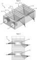
Figure 1 shows a thermal energy storage apparatus according to one embodiment of the present invention; -
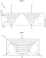
Figures 2 to 5 are respective perspective, plan, side and end views of a block of heat absorbing material for use with the thermal energy storage apparatus; -
Figures 6 to 9 are respective perspective, plan, side and end views of another block of heat absorbing material; and -
Figures 10 to 12 are respective plan, side and end views of another block of heat absorbing material. - Referring initially to
Figure 1 , there is shown a thermalenergy storage apparatus 10 according to a preferred embodiment of the present invention. - The thermal
energy storage apparatus 10 includes ablock 12 of a heat-absorbing material. As illustrated inFigures 2 to 5 , theblock 12 defines at least onereceptacle 14 in which phase change material can be received. In this regard, theblock 12 may be formed with a single receptacle as illustrated inFigures 10 to 12 , twin receptacles as illustrated inFigures 2 to 9 , or greater than two receptacles. Theblock 12 is a contiguous block of compressed sintered graphite which is machinable. - As used herein, the term "contiguous" refers to a single mass of material, whether solid or porous, in which any two points within the mass may be joined by a continuous path. By being "contiguous" the block is a single or unitary piece of heat absorbing material. The block is not composed of an assemblage of multiple, discrete pieces of heat absorbing material.
- By the block defining at least one "receptacle" is meant that the block is shaped to have at least one cavity that can receive the phase change material. For example, a receptacle may be formed in the block of compressed sintered graphite by a material removal process in which graphite is removed to form a cavity in the block. This may be achieved, for example, by machining the block.
- A phase change material which expands on cooling, in this case silicon metalloid, is stored within the
receptacles 14. As illustrated inFigures 2 to 12 , side walls of thereceptacles 14 are formed with a progressively decreasing wall angle as they extend upwardly from abase 16 of the receptacle. In this regard, portions of the wall that are closer to the base 16 are at or near to vertical, with the wall angle decreasing closer to horizontal as the wall extends away from the base. Although a lowermost portion of the walls may be vertical, the height of any such portions would be minimized. - The described configuration of the walls of the
receptacles 14 provides that as the phase change material cools and expands it is urged upwardly to disperse pressure and reduce the amount of pressure applied to theblock 12, thereby reducing cracking or fissuring of theblock 12 over thermal cycling. - By the phase change material being "urged upwardly" is meant that as the phase change material solidifies it expands towards the mouth of the receptacle as a result of the counter pressure offered by the surface of the receptacle. In other words, the present invention provides a block of a heat-absorbing material, the block (i) defining at least one receptacle having a mouth and a base, and (ii) being a contiguous block of compressed sintered graphite; and a phase change material stored in the or each receptacle, the phase change material being one that expands as it cools, wherein separation of side walls of the or each receptacle progressively increases as they extend upwardly from the base to the mouth of the receptacle, whereby as the phase change material solidifies it expands towards the mouth of the receptacle to reduce pressure applied to the heat-absorbing material.
- In some embodiments, the side walls of the
receptacle 14 are separated intodiscrete sections 15. Provided the horizontal cross-section of the receptacle increases along an upward direction, there is no particular limitation to the specific design of thesections 15. - In some embodiments, a vertical cross-section of the receptacle has a step-wise profile. In such embodiments, a side wall of the receptacle is such that each
section 15 has a vertical wall alternating with a horizontal step to provide a step-like profile. The step-wise change in wall profile is such that the separation distance between the side walls of receptacle increases from its base towards its top. - In other embodiments, a vertical cross-section of the receptacle has an angular profile. In such embodiments, a side wall is such that each
section 15 is inclined at an angle relative to the vertical direction. The sections can each have a constant angle in which case, the side wall can be at a constant angle (as inFigures 10 and 11 ). Alternatively, the angle of one or more thesections 15 can vary as they extend from the base of the receptacle, for example, the incline ofsections 15 in the upper part of the side wall can decrease as the sections extend away from the base, i.e. a lower most section can be more vertical than an uppermost section. In all cases, the distance between side walls increase as they extend away from the base. - In other embodiments, a vertical cross-section of a side wall the receptacle can have a combination of a step-wise and angular profile. For instance, as shown in
Figure 4 ,lower sections 15a of the side wall of the receptacle can be step-like, whileupper sections 15b of the side wall can have an angular profile. - In other embodiments, the
sections 15 may have a curved face. Adiscrete section 15 can be separated from the section adjacent to it by agroove 18 formed in the block. Preferably, the discrete sections are each separated by agroove 18 formed in the block, thegroove 18 extending around a surface of thereceptacle 14.Groove 18 further allows pressure dispersement of the expanding phase change material by providing a relief into which the material can flow under pressure. - In alternative embodiments,
grooves 18 may be omitted. Also, the side walls may be curved to provide a progressively decreasing wall angle. - In the illustrated embodiment, a
base 16 of the receptacle is rectangular and forms a trough. It will be appreciated that the base may take the shape of other polygons, preferably regular polygons, or be circular, though it has been found that a rectangular shape is most desirable and allows the amount of graphite used in theblock 12 to be minimised while maximising the amount of phase change material that can be contained in thereceptacle 14, thereby increasing the efficiency of the apparatus without rendering the block prone to damage. Also, a rectangular base renders the receptacle mechanically stronger than, for example, an angled base (i.e. as in a receptacle having a vertical cross-section shaped as a "V"). This advantageously ensures that theblock 12 can better withstand the lateral pressure generated during solidification of the phase change material. -
Figures 6 to 9 and10 to 12 illustratealternative blocks 112, 212 that take slightly different shapes and show that variations are possible within the scope of the present disclosure. - In particular, block 112 of
Figures 6 to 9 has a slightlywider base 116 to accommodate more phase change material and the separation of thesections 115 of the side walls are staggered and progressively increase as they extend upwardly from the base. - On the other hand,
Figures 10 to 12 show a block 212 having asingle receptacle 214 in whichsections 215, which define the surface of the receptacle and are separated bygrooves 218, have constant wall angle . - During cooling, an area of an upper surface of the phase change material forms a dome. This is a result of the portion of the phase change material in contact with the
block 12 cooling first, leaving a central portion of the phase change material in a liquid state and capable of being moved upwardly as the phase change material cools. - Regarding the phase change material, silicon metalloid has a latent heat storage capacity of approximately 497 W/kg at a temperature of 1410°C. In some circumstances it may be advantageous to employ, instead of silicon metalloid, a eutectic (or hypoeutectic or hypereutectic) silicon composition, which has a lower heat capacity but also a lower phase transition temperature. For example, a eutectic Al-Si alloy having an Al:Si ratio of 1:12 has a much lower transition temperature of 580°C, whilst still having a relatively large storage capacity of approximately 200 W/kg.
- The phase change material of the thermal energy storage apparatus can be in a suitable form. In one embodiment, the phase change material can be in the form of an ingot.
- The heat-absorbing material is a
contiguous block 12 of compressed sintered graphite, which is machinable. By the sintered graphite being "compressed" is meant that the sintered graphite is compressed into shape. The resulting compressed sintered graphite can then be machined to provide, for example, the receptacles and other shape features depending on the intended use. As a result of being compressed, compressed sintered graphite is denser than sintered graphite. By providing acontiguous block 12 of compressed sintered graphite, many advantages can be obtained. Firstly, liquid silicon is not absorbed by the compressed sintered graphite, thereby allowing containment tubes to be omitted. Also, when a contiguous block of graphite is made and is compressed, a "charged" block is obtained. In a charged block of compressed sintered graphite atoms align in the direction of a current applied thereto, therefore allowing increased heat transfer and thereby increasing the efficiency of the apparatus. -
Block 12 may also include a binder or have other material impregnated therein and/or be coated. In a preferred form, theblock 12 is impregnated with a highly crystalline petroleum coke, such as needle or acicular coke. This provides increased heat transfer rate across theblock 12. In a preferred form, theblock 12 is also coated with a coating to protect it from oxidisation. In one example, the coating may be a silicon carbide slurry. - Manufacturing of the
block 12, in particular formation of the receptacles, is performed by machining a raw block of compressed sintered graphite. In other forms, theblock 12 may also be moulded or cast in a mould and compressed while moulding. Ends of the block may also be machined to accept an end of a Stirling engine, as described further below, or in other forms the block may be machined to allow connection to a turbomachine. While sintered graphite is used in the presently described embodiments, there is also disclosed that other heat-absorbing materials may be suitable, provided they have suitably high thermal conductivity and can be machined into a shape to accommodate the phase-change material and its expansion upon solidification. - In operation of the thermal
energy storage apparatus 10, electric current is supplied to theelectric heating elements 20 by an external energy source. For example, the current may be a DC current from a photovoltaic array or an AC current from a wind turbine. As current passes through theheating elements 20, resistive heating of the surrounding graphite results.Electric heating elements 20 are provided in close proximity to and around theblock 12 and are in thermal contact with theblock 12. By theelectric heating elements 20 being "in thermal contact" with theblock 12 is meant any arrangement that allows for heat transfer between theelectric heating elements 20 and theblock 12. Preferably, theblock 12 is provided within anenclosure 26 of theapparatus 10, and theheating elements 20 are disposed in slots 24 formed in insulation inside theenclosure 26. Theenclosure 26 can be formed of any suitable material. For example, theenclosure 26 may be made of mild steel. - In some forms, the
electric heating elements 20 are disposed only along long edges of theblock 12 so that ends of theblock 12, which is where the Sterling engine is positioned, are slightly cooler to encourage flow of heat toward the engine. Advantageously, heat can flow along the block, thereby allowing simultaneous charging and discharging, i.e. storage of heat from the heating elements and extraction of heat via the Sterling engine. - Heat is then transported to the phase change material of the heat storage apparatus via
block 12. The silicon metalloid (or eutectic silicon composition, for example) absorbs sensible heat until its temperature reaches melting temperature, at which point further heat input to the silicon metalloid is stored as latent heat of fusion. When the external energy source (solar or wind) is no longer available, or drops below the level required to maintain the core temperature of the phase change material above the melting temperature, the silicon metalloid solidifies. The stored heat is then released to the surrounding graphite. - The
heating elements 20 are preferably formed of graphite, and may be coupled to a current source in conventional fashion, for example by copper cabling. In a preferred embodiment, theheating elements 20 are formed of compressed sintered graphite, providing for efficient heating. In alternative embodiments, theheating elements 20 are made of an iron-chromium-aluminium alloy (FeCrAl), for example Kanthal. - Alternatively, the
block 12 can be heated directly by solar energy, for example by providing one or more solar concentrators to focus sunlight onto theblock 12 at one or more locations, or via hot gases exhausted from a turbomachine. Providingelectric heating elements 20 at predetermined locations affords greater control over heating of theblock 12, and allows it to be used in conjunction with electricity generation systems, particularly renewable electricity generation systems that have unused electrical energy that can be sent back to the elements to top up their storage instead of being grounded. - In order to extract heat to perform mechanical and/or electrical work, the
apparatus 10 can be coupled to a Carnot cycle heat engine, such as a Stirling engine or a Brayton engine, or to turbine machinery. In the illustrated example, twoStirling engines 22 are coupled to theblock 12 of theenergy storage apparatus 10, such that an end of each Stirling engine can receive heat throughapertures 17 which are formed in theblock 12. When the phase-change material (located within the receptacles) stores heat, a temperature gradient forms between the core of the phase change material (hot side) and the Stirling engine (cold side), resulting in heat being transferred from the phase change material to each Stirling engine through theblock 12 of compressed sintered graphite. - Preferably, as shown in the embodiment of
Figure 1 , theapertures 17 are formed in the end of theblock 12 that do not compriseheating elements 20, that side being cooler than the side where theheating elements 20 are located. In this arrangement the temperature gradient between the core of the phase change material (hot side) and the Stirling engines 22 (cold side) is increased, thereby improving the efficiency at which heat travels from the phase change material to theengines 22 through theblock 12 of compressed sintered graphite. When the core of the phase-change material is at a higher temperature than the head of the heat engine, heat is transported from the phase-change material by thermal conduction. In alternative embodiments, a wick may be provided for connection of the engine to theblock 12. In some embodiments, theapparatus 10 is in communication with a plurality of closed-cycle heat engines. - Different areas of the
block 12 may heat at different rates and can each have one or more temperature sensors associated therewith. Temperature readings from each sensor may be communicated to a control system (not shown), and the readings used by the control system to adjust the electric current flowing to theheating elements 20, and thus the degree of heating of the block. - The apparatus is disposed within a housing, which is preferably formed of mild steel, the block is sandwiched between upper, lower and side layers of an insulating material. The layers may employ different insulating materials depending on the operating temperatures experienced by the top and bottom of the
apparatus 10. - In some embodiments, the apparatus is disposed within a housing that is substantially evacuated or filled with nitrogen. These arrangements advantageously provide improved thermal insulation for optimised heat transfer between the phase-change material and the Carnot cycle heat engine or turbine machinery coupled to the apparatus.
- In some embodiments, the apparatus is disposed in an oxygen free environment. This advantageously minimises oxidation of the heat absorbing material forming the receptacle to preserve its heat transfer characteristics.
- A further aspect of the invention relates to a method of storing thermal energy, including the steps of (i) providing a thermal energy storage apparatus of the kind described herein, and (ii) providing thermal energy to the phase change material. The provision of thermal energy to the phase change material may be achieved by any means described herein.
- A plurality of apparatuses of the above described type may be used to form a thermal energy storage system to provide scalable storage as required. In one form, the apparatuses are arranged side by side and are preferably enclosed to trap excess heat. In another form, the apparatuses are arranged in a hole formed in the ground, the hole being lined with concrete around sides thereof.
- Many modifications of the above embodiments will be apparent to those skilled in the art without departing from the scope of the present invention as defined by the appended claims.
- Throughout this specification, unless the context requires otherwise, the word "comprise", and variations such as "comprises" and "comprising", will be understood to imply the inclusion of a stated integer or step or group of integers or steps but not the exclusion of any other integer or step or group of integers or steps.
Claims (15)
- A thermal energy storage apparatus (10), including:a block of a heat-absorbing material (12), the block defining at least one receptacle (14) comprising side walls and a base (16) and being a contiguous block of compressed sintered graphite; anda phase change material stored in the or each receptacle (14), the phase change material being one that expands as it cools,characterised in that the block is configured that separation of the side walls of the or each receptacle (14) progressively increases as they extend upwardly from the base (16), whereby as the phase change material solidifies and expands it is urged upwardly to reduce pressure applied to the heat-absorbing material (12).
- A thermal energy storage apparatus (10) according to claim 1, wherein the side walls are formed with a progressively decreasing wall angle as they extend upwardly from the base.
- A thermal energy storage apparatus (10) according to claim 1 or claim 2, wherein the side walls are separated into discrete sections having a constant wall angle.
- A thermal energy storage apparatus (10) according to claim 3, wherein the discrete sections are separated by a groove (18) formed in the block, the groove (18) extending around a surface of the receptacle (14).
- A thermal energy storage apparatus (10) according to any one of the preceding claims, further including one or more heating elements (20) in thermal contact with the heat absorbing material (12), wherein the one or more heating elements (20) extend alongside an outer surface of the block (12).
- A thermal energy storage apparatus (10) according to claim 5, wherein the heating elements (20) are electric heating elements, in particular graphite heating elements.
- A thermal energy storage apparatus (10) according to any one of the preceding claims, further including means for extracting heat from the block (12), wherein the means for extracting heat is at least one closed-cycle heat engine (22) or turbomachine coupled to the block (12).
- A thermal energy storage apparatus (10) according to claim 7, wherein the at least one closed-cycle heat engine (22) is a Stirling engine and an end of the Stirling engine is received in an aperture formed (17) in the block.
- A thermal energy storage apparatus (10) according to any one of the preceding claims, wherein the phase change material includes silicon metalloid or a eutectic, hypereutectic or hypoeutectic silicon composition.
- A thermal energy storage apparatus (10) according to any one of the preceding claims, wherein the phase change material is formed as an ingot.
- A thermal energy storage apparatus (10) according to any one of the preceding claims, wherein the block of heat-absorbing material (12) is injected with a highly crystalline petroleum coke.
- A thermal energy storage apparatus (10) according to any one of the preceding claims, wherein the receptacle (14) is disposed within a housing (26) that is substantially evacuated or filled with nitrogen.
- A thermal energy storage system, including a plurality of apparatuses (10) according to any one of claims 1 to 12, the apparatuses (10) being in communication with a plurality of closed-cycle heat engines (22).
- A method of storing thermal energy, including the steps of:providing a thermal energy storage apparatus (10) according to any preceding claim; andproviding thermal energy to the phase change material;characterised in that separation of side walls of the or each receptacle (14) progressively increases as they extend upwardly from the base (16), thus urging upwardly the solidifying and expanding phase change material and thus reducing pressure applied to the heat-absorbing material (12).
- A method according to claim 14, wherein a receptacle (14) of the thermal energy storage apparatus (10) is disposed in an oxygen free environment.
Priority Applications (2)
| Application Number | Priority Date | Filing Date | Title |
|---|---|---|---|
| SI201831213T SI3619490T1 (en) | 2017-05-03 | 2018-05-03 | Thermal energy storage apparatus |
| HRP20250185TT HRP20250185T1 (en) | 2017-05-03 | 2018-05-03 | HEAT ENERGY STORAGE DEVICE |
Applications Claiming Priority (2)
| Application Number | Priority Date | Filing Date | Title |
|---|---|---|---|
| AU2017901612A AU2017901612A0 (en) | 2017-05-03 | Thermal energy storage apparatus | |
| PCT/AU2018/050405 WO2018201193A1 (en) | 2017-05-03 | 2018-05-03 | Thermal energy storage apparatus |
Publications (3)
| Publication Number | Publication Date |
|---|---|
| EP3619490A1 EP3619490A1 (en) | 2020-03-11 |
| EP3619490A4 EP3619490A4 (en) | 2021-03-03 |
| EP3619490B1 true EP3619490B1 (en) | 2024-11-20 |
Family
ID=64015932
Family Applications (1)
| Application Number | Title | Priority Date | Filing Date |
|---|---|---|---|
| EP18794502.7A Active EP3619490B1 (en) | 2017-05-03 | 2018-05-03 | Thermal energy storage apparatus |
Country Status (12)
| Country | Link |
|---|---|
| US (1) | US11067344B2 (en) |
| EP (1) | EP3619490B1 (en) |
| AU (1) | AU2018262109C1 (en) |
| CA (1) | CA3061766C (en) |
| DK (1) | DK3619490T3 (en) |
| ES (1) | ES3011533T3 (en) |
| FI (1) | FI3619490T3 (en) |
| HR (1) | HRP20250185T1 (en) |
| HU (1) | HUE071238T2 (en) |
| LT (1) | LT3619490T (en) |
| SI (1) | SI3619490T1 (en) |
| WO (1) | WO2018201193A1 (en) |
Families Citing this family (7)
| Publication number | Priority date | Publication date | Assignee | Title |
|---|---|---|---|---|
| LU100895B1 (en) * | 2016-12-08 | 2018-12-18 | Patrick Joseph Glynn | APPARATUS AND METHODS FOR ENERGY STORAGE AND RECOVERY |
| HUE071238T2 (en) | 2017-05-03 | 2025-08-28 | Green Energy Invest Ip | Thermal energy storage device |
| US10914293B2 (en) | 2018-06-20 | 2021-02-09 | David Alan McBay | Method, system and apparatus for extracting heat energy from geothermal briny fluid |
| MA56210A (en) | 2019-06-12 | 2022-04-20 | Energynest As | THERMAL ENERGY BATTERY |
| CA3189700A1 (en) * | 2020-09-21 | 2022-03-24 | Heiko Schwertner | Device for receiving, storing and releasing thermal energy |
| WO2023023762A1 (en) * | 2021-08-25 | 2023-03-02 | RESCU.EARTH Pty Ltd | Thermal energy storage cell |
| US12578152B2 (en) | 2021-09-22 | 2026-03-17 | Wellhead Power Solutions, Llc | Thermal energy storage system |
Family Cites Families (31)
| Publication number | Priority date | Publication date | Assignee | Title |
|---|---|---|---|---|
| US3370418A (en) | 1966-10-24 | 1968-02-27 | Donald A. Kelly | Rotary stirling cycle engines |
| US3548930A (en) | 1969-07-30 | 1970-12-22 | Ambrose W Byrd | Isothermal cover with thermal reservoirs |
| US4149525A (en) * | 1977-10-14 | 1979-04-17 | Prado David A | Solar collector |
| US4830092A (en) | 1986-10-27 | 1989-05-16 | Rockwell International Corporation | Heat enhancers and salt purifiers for thermal energy storage canister |
| JPH0760075B2 (en) * | 1987-01-31 | 1995-06-28 | 株式会社東芝 | Heat storage device |
| DE3905707A1 (en) * | 1989-02-24 | 1990-08-30 | Deutsche Forsch Luft Raumfahrt | HEAT STORAGE WITH EXPANDING EXPANSION AREA |
| US5201606A (en) * | 1990-06-25 | 1993-04-13 | Carolina Power & Light Company | Thermal storage tank and associated top structure |
| US5074283A (en) | 1990-08-10 | 1991-12-24 | The United States Department Of Energy | Thermal storage module for solar dynamic receivers |
| DE4232556A1 (en) * | 1992-09-29 | 1994-03-31 | Laengerer & Reich Gmbh & Co | Process for producing a heat store, in particular latent heat store |
| US5694515A (en) | 1995-01-09 | 1997-12-02 | The University Of Florida | Contact resistance-regulated storage heater for fluids |
| US5571232A (en) * | 1995-06-02 | 1996-11-05 | Carolina Power & Light Company | Thermal energy storage tank containing submerged ice mass |
| US7524385B2 (en) | 2006-10-03 | 2009-04-28 | Elemetric, Llc | Controlled phase transition of metals |
| WO2009031968A1 (en) | 2007-09-03 | 2009-03-12 | Marcus Lehto | Multi-stable actuator |
| US8584734B2 (en) | 2008-02-11 | 2013-11-19 | Navatek, Ltd | Two material phase change energy storage system |
| US20100212656A1 (en) | 2008-07-10 | 2010-08-26 | Infinia Corporation | Thermal energy storage device |
| US7971437B2 (en) | 2008-07-14 | 2011-07-05 | Bell Independent Power Corporation | Thermal energy storage systems and methods |
| DE112008003941T5 (en) * | 2008-07-16 | 2011-05-26 | Exencotech Ab | Energy system with phase change material |
| AU2010282232B2 (en) * | 2009-08-14 | 2016-02-04 | Latent Heat Storage Pty Ltd | Thermal energy storage apparatus, arrangement and method |
| GB0919934D0 (en) * | 2009-11-16 | 2009-12-30 | Sunamp Ltd | Energy storage systems |
| DE102009060911A1 (en) | 2009-12-31 | 2011-07-07 | Deutsches Zentrum für Luft- und Raumfahrt e.V. (DLR), 51147 | Device and system for temporary storage of thermal energy |
| DE102010004358A1 (en) * | 2010-01-12 | 2011-06-16 | Deutsches Zentrum für Luft- und Raumfahrt e.V. | Latent heat accumulator for use as e.g. overheating protection device in open solar receiver system of solar power station, has cells are made of high temperature-steady material and limit at channel, where fluid flows through channel |
| CH703780A2 (en) * | 2010-08-30 | 2012-03-15 | Airlight Energy Ip Sa | Heat storage. |
| US20120055661A1 (en) | 2010-09-03 | 2012-03-08 | Peter Feher | High temperature thermal energy storage system |
| DE202011000830U1 (en) | 2011-04-08 | 2011-08-05 | Dieter Girlich | convection heat |
| ES2624187T3 (en) * | 2011-08-09 | 2017-07-13 | Thermal energy storage device | |
| US9115937B2 (en) * | 2011-12-15 | 2015-08-25 | Virgil Dewitt Perryman | Thermal energy storage and delivery system |
| TWI532890B (en) * | 2012-06-25 | 2016-05-11 | 希利柯爾材料股份有限公司 | Controlled directional solidification of silicon |
| DE102012212837B4 (en) * | 2012-07-23 | 2016-12-29 | BankWare Ltd. | Device for the use of radiant energy |
| FR2999336A1 (en) * | 2012-12-07 | 2014-06-13 | Commissariat Energie Atomique | ELECTRONIC COMPONENT COMPRISING A HEAT ABSORBER MATERIAL AND METHOD FOR MANUFACTURING THE ELECTRONIC COMPONENT |
| FR3024214A3 (en) * | 2014-07-23 | 2016-01-29 | Muller & Cie Soc | SEASONAL THERMOELECTRIC STORAGE APPARATUS |
| HUE071238T2 (en) | 2017-05-03 | 2025-08-28 | Green Energy Invest Ip | Thermal energy storage device |
-
2018
- 2018-05-03 HU HUE18794502A patent/HUE071238T2/en unknown
- 2018-05-03 LT LTEPPCT/AU2018/050405T patent/LT3619490T/en unknown
- 2018-05-03 FI FIEP18794502.7T patent/FI3619490T3/en active
- 2018-05-03 AU AU2018262109A patent/AU2018262109C1/en active Active
- 2018-05-03 ES ES18794502T patent/ES3011533T3/en active Active
- 2018-05-03 US US16/610,339 patent/US11067344B2/en active Active
- 2018-05-03 EP EP18794502.7A patent/EP3619490B1/en active Active
- 2018-05-03 CA CA3061766A patent/CA3061766C/en active Active
- 2018-05-03 SI SI201831213T patent/SI3619490T1/en unknown
- 2018-05-03 WO PCT/AU2018/050405 patent/WO2018201193A1/en not_active Ceased
- 2018-05-03 DK DK18794502.7T patent/DK3619490T3/en active
- 2018-05-03 HR HRP20250185TT patent/HRP20250185T1/en unknown
Also Published As
| Publication number | Publication date |
|---|---|
| DK3619490T3 (en) | 2025-02-17 |
| HRP20250185T1 (en) | 2025-08-01 |
| LT3619490T (en) | 2025-05-26 |
| AU2018262109A1 (en) | 2019-08-08 |
| CA3061766C (en) | 2021-12-14 |
| AU2018262109C1 (en) | 2022-12-15 |
| US11067344B2 (en) | 2021-07-20 |
| ES3011533T3 (en) | 2025-04-07 |
| FI3619490T3 (en) | 2025-02-19 |
| EP3619490A4 (en) | 2021-03-03 |
| HUE071238T2 (en) | 2025-08-28 |
| CA3061766A1 (en) | 2018-11-08 |
| US20200088473A1 (en) | 2020-03-19 |
| WO2018201193A1 (en) | 2018-11-08 |
| EP3619490A1 (en) | 2020-03-11 |
| AU2018262109B2 (en) | 2019-09-19 |
| SI3619490T1 (en) | 2025-07-31 |
Similar Documents
| Publication | Publication Date | Title |
|---|---|---|
| EP3619490B1 (en) | Thermal energy storage apparatus | |
| AU2012292959B2 (en) | Thermal energy storage apparatus | |
| EP1730460B1 (en) | Method and apparatus for storing heat energy | |
| US20130056169A1 (en) | Energy handling system comprising an energy storage device with a phase change material | |
| US20110203573A1 (en) | Solar Collector | |
| US20200132393A1 (en) | Thermal Cell | |
| AU2020243828B2 (en) | An energy conversion, storage and retrieval device and method | |
| AU2014259137A1 (en) | Packed rock bed thermal energy storage facility | |
| US20200340759A1 (en) | Apparatus and methods for energy storage and retrieval | |
| US12498182B2 (en) | Energy storage device and method of heating a heat transfer fluid | |
| HK1201318B (en) | Thermal energy storage apparatus |
Legal Events
| Date | Code | Title | Description |
|---|---|---|---|
| REG | Reference to a national code |
Ref country code: HR Ref legal event code: TUEP Ref document number: P20250185T Country of ref document: HR |
|
| STAA | Information on the status of an ep patent application or granted ep patent |
Free format text: STATUS: THE INTERNATIONAL PUBLICATION HAS BEEN MADE |
|
| PUAI | Public reference made under article 153(3) epc to a published international application that has entered the european phase |
Free format text: ORIGINAL CODE: 0009012 |
|
| STAA | Information on the status of an ep patent application or granted ep patent |
Free format text: STATUS: REQUEST FOR EXAMINATION WAS MADE |
|
| 17P | Request for examination filed |
Effective date: 20191104 |
|
| AK | Designated contracting states |
Kind code of ref document: A1 Designated state(s): AL AT BE BG CH CY CZ DE DK EE ES FI FR GB GR HR HU IE IS IT LI LT LU LV MC MK MT NL NO PL PT RO RS SE SI SK SM TR |
|
| AX | Request for extension of the european patent |
Extension state: BA ME |
|
| DAV | Request for validation of the european patent (deleted) | ||
| DAX | Request for extension of the european patent (deleted) | ||
| A4 | Supplementary search report drawn up and despatched |
Effective date: 20210128 |
|
| RIC1 | Information provided on ipc code assigned before grant |
Ipc: F02G 1/04 20060101ALI20210122BHEP Ipc: F01K 3/12 20060101ALI20210122BHEP Ipc: F03G 6/06 20060101ALI20210122BHEP Ipc: F01K 23/02 20060101ALI20210122BHEP Ipc: F28D 20/02 20060101AFI20210122BHEP Ipc: C09K 5/06 20060101ALI20210122BHEP Ipc: F01K 3/18 20060101ALI20210122BHEP Ipc: F28D 20/00 20060101ALI20210122BHEP Ipc: F28F 21/02 20060101ALI20210122BHEP Ipc: F01K 3/02 20060101ALI20210122BHEP |
|
| RIC1 | Information provided on ipc code assigned before grant |
Ipc: F28F 21/02 20060101ALI20231113BHEP Ipc: F28D 20/00 20060101ALI20231113BHEP Ipc: F01K 3/18 20060101ALI20231113BHEP Ipc: F01K 3/12 20060101ALI20231113BHEP Ipc: F01K 3/02 20060101ALI20231113BHEP Ipc: F03G 6/06 20060101ALI20231113BHEP Ipc: F02G 1/04 20060101ALI20231113BHEP Ipc: F01K 23/02 20060101ALI20231113BHEP Ipc: C09K 5/06 20060101ALI20231113BHEP Ipc: F28D 20/02 20060101AFI20231113BHEP |
|
| GRAP | Despatch of communication of intention to grant a patent |
Free format text: ORIGINAL CODE: EPIDOSNIGR1 |
|
| STAA | Information on the status of an ep patent application or granted ep patent |
Free format text: STATUS: GRANT OF PATENT IS INTENDED |
|
| INTG | Intention to grant announced |
Effective date: 20240102 |
|
| GRAJ | Information related to disapproval of communication of intention to grant by the applicant or resumption of examination proceedings by the epo deleted |
Free format text: ORIGINAL CODE: EPIDOSDIGR1 |
|
| STAA | Information on the status of an ep patent application or granted ep patent |
Free format text: STATUS: REQUEST FOR EXAMINATION WAS MADE |
|
| INTC | Intention to grant announced (deleted) | ||
| GRAP | Despatch of communication of intention to grant a patent |
Free format text: ORIGINAL CODE: EPIDOSNIGR1 |
|
| GRAP | Despatch of communication of intention to grant a patent |
Free format text: ORIGINAL CODE: EPIDOSNIGR1 |
|
| STAA | Information on the status of an ep patent application or granted ep patent |
Free format text: STATUS: GRANT OF PATENT IS INTENDED |
|
| INTG | Intention to grant announced |
Effective date: 20240614 |
|
| GRAS | Grant fee paid |
Free format text: ORIGINAL CODE: EPIDOSNIGR3 |
|
| GRAA | (expected) grant |
Free format text: ORIGINAL CODE: 0009210 |
|
| STAA | Information on the status of an ep patent application or granted ep patent |
Free format text: STATUS: THE PATENT HAS BEEN GRANTED |
|
| AK | Designated contracting states |
Kind code of ref document: B1 Designated state(s): AL AT BE BG CH CY CZ DE DK EE ES FI FR GB GR HR HU IE IS IT LI LT LU LV MC MK MT NL NO PL PT RO RS SE SI SK SM TR |
|
| REG | Reference to a national code |
Ref country code: GB Ref legal event code: FG4D |
|
| REG | Reference to a national code |
Ref country code: CH Ref legal event code: EP |
|
| REG | Reference to a national code |
Ref country code: DE Ref legal event code: R096 Ref document number: 602018076762 Country of ref document: DE |
|
| REG | Reference to a national code |
Ref country code: IE Ref legal event code: FG4D |
|
| REG | Reference to a national code |
Ref country code: DK Ref legal event code: T3 Effective date: 20250210 |
|
| REG | Reference to a national code |
Ref country code: FI Ref legal event code: FGE |
|
| REG | Reference to a national code |
Ref country code: SE Ref legal event code: TRGR |
|
| REG | Reference to a national code |
Ref country code: NL Ref legal event code: FP |
|
| P01 | Opt-out of the competence of the unified patent court (upc) registered |
Free format text: CASE NUMBER: APP_5919/2025 Effective date: 20250204 |
|
| REG | Reference to a national code |
Ref country code: ES Ref legal event code: FG2A Ref document number: 3011533 Country of ref document: ES Kind code of ref document: T3 Effective date: 20250407 |
|
| PG25 | Lapsed in a contracting state [announced via postgrant information from national office to epo] |
Ref country code: PT Free format text: LAPSE BECAUSE OF FAILURE TO SUBMIT A TRANSLATION OF THE DESCRIPTION OR TO PAY THE FEE WITHIN THE PRESCRIBED TIME-LIMIT Effective date: 20250320 |
|
| PG25 | Lapsed in a contracting state [announced via postgrant information from national office to epo] |
Ref country code: LV Free format text: LAPSE BECAUSE OF FAILURE TO SUBMIT A TRANSLATION OF THE DESCRIPTION OR TO PAY THE FEE WITHIN THE PRESCRIBED TIME-LIMIT Effective date: 20241120 |
|
| PG25 | Lapsed in a contracting state [announced via postgrant information from national office to epo] |
Ref country code: PL Free format text: LAPSE BECAUSE OF FAILURE TO SUBMIT A TRANSLATION OF THE DESCRIPTION OR TO PAY THE FEE WITHIN THE PRESCRIBED TIME-LIMIT Effective date: 20241120 |
|
| PG25 | Lapsed in a contracting state [announced via postgrant information from national office to epo] |
Ref country code: RS Free format text: LAPSE BECAUSE OF FAILURE TO SUBMIT A TRANSLATION OF THE DESCRIPTION OR TO PAY THE FEE WITHIN THE PRESCRIBED TIME-LIMIT Effective date: 20250220 |
|
| PGFP | Annual fee paid to national office [announced via postgrant information from national office to epo] |
Ref country code: NL Payment date: 20250425 Year of fee payment: 8 |
|
| REG | Reference to a national code |
Ref country code: EE Ref legal event code: FG4A Ref document number: E024968 Country of ref document: EE Effective date: 20250213 |
|
| PGFP | Annual fee paid to national office [announced via postgrant information from national office to epo] |
Ref country code: LU Payment date: 20250425 Year of fee payment: 8 |
|
| RAP2 | Party data changed (patent owner data changed or rights of a patent transferred) |
Owner name: GREEN ENERGY INVESTMENTS IPPORTFOLIO 3 FZC LLC |
|
| REG | Reference to a national code |
Ref country code: HR Ref legal event code: ODRP Ref document number: P20250185T Country of ref document: HR Payment date: 20250429 Year of fee payment: 8 |
|
| REG | Reference to a national code |
Ref country code: HU Ref legal event code: HC9C Owner name: GREEN ENERGY INVESTMENTS IP, AE Free format text: FORMER OWNER(S): CLIMATE CHANGE TECHNOLOGIES PTY LTD, AU |
|
| REG | Reference to a national code |
Ref country code: GB Ref legal event code: 732E Free format text: REGISTERED BETWEEN 20250605 AND 20250611 |
|
| PG25 | Lapsed in a contracting state [announced via postgrant information from national office to epo] |
Ref country code: SM Free format text: LAPSE BECAUSE OF FAILURE TO SUBMIT A TRANSLATION OF THE DESCRIPTION OR TO PAY THE FEE WITHIN THE PRESCRIBED TIME-LIMIT Effective date: 20241120 |
|
| PGFP | Annual fee paid to national office [announced via postgrant information from national office to epo] |
Ref country code: FI Payment date: 20250425 Year of fee payment: 8 |
|
| PGFP | Annual fee paid to national office [announced via postgrant information from national office to epo] |
Ref country code: DE Payment date: 20250425 Year of fee payment: 8 |
|
| PGFP | Annual fee paid to national office [announced via postgrant information from national office to epo] |
Ref country code: DK Payment date: 20250425 Year of fee payment: 8 Ref country code: GB Payment date: 20250425 Year of fee payment: 8 |
|
| PGFP | Annual fee paid to national office [announced via postgrant information from national office to epo] |
Ref country code: LT Payment date: 20250428 Year of fee payment: 8 |
|
| PGFP | Annual fee paid to national office [announced via postgrant information from national office to epo] |
Ref country code: IS Payment date: 20250512 Year of fee payment: 8 Ref country code: HU Payment date: 20250528 Year of fee payment: 8 Ref country code: NO Payment date: 20250425 Year of fee payment: 8 |
|
| PGFP | Annual fee paid to national office [announced via postgrant information from national office to epo] |
Ref country code: IT Payment date: 20250530 Year of fee payment: 8 Ref country code: BE Payment date: 20250425 Year of fee payment: 8 |
|
| PGFP | Annual fee paid to national office [announced via postgrant information from national office to epo] |
Ref country code: HR Payment date: 20250429 Year of fee payment: 8 |
|
| REG | Reference to a national code |
Ref country code: HR Ref legal event code: PPPP Ref document number: P20250185T Country of ref document: HR Owner name: GREEN ENERGY INVESTMENTS IP PORTFOLIO 3 FZC LLC, AE |
|
| PGFP | Annual fee paid to national office [announced via postgrant information from national office to epo] |
Ref country code: EE Payment date: 20250530 Year of fee payment: 8 Ref country code: FR Payment date: 20250528 Year of fee payment: 8 |
|
| PGFP | Annual fee paid to national office [announced via postgrant information from national office to epo] |
Ref country code: MT Payment date: 20250512 Year of fee payment: 8 Ref country code: GR Payment date: 20250523 Year of fee payment: 8 Ref country code: BG Payment date: 20250521 Year of fee payment: 8 |
|
| PGFP | Annual fee paid to national office [announced via postgrant information from national office to epo] |
Ref country code: CH Payment date: 20250601 Year of fee payment: 8 |
|
| PG25 | Lapsed in a contracting state [announced via postgrant information from national office to epo] |
Ref country code: RO Free format text: LAPSE BECAUSE OF FAILURE TO SUBMIT A TRANSLATION OF THE DESCRIPTION OR TO PAY THE FEE WITHIN THE PRESCRIBED TIME-LIMIT Effective date: 20241120 |
|
| PGFP | Annual fee paid to national office [announced via postgrant information from national office to epo] |
Ref country code: AT Payment date: 20250522 Year of fee payment: 8 |
|
| PG25 | Lapsed in a contracting state [announced via postgrant information from national office to epo] |
Ref country code: SK Free format text: LAPSE BECAUSE OF FAILURE TO SUBMIT A TRANSLATION OF THE DESCRIPTION OR TO PAY THE FEE WITHIN THE PRESCRIBED TIME-LIMIT Effective date: 20241120 |
|
| PGFP | Annual fee paid to national office [announced via postgrant information from national office to epo] |
Ref country code: TR Payment date: 20250428 Year of fee payment: 8 |
|
| PGFP | Annual fee paid to national office [announced via postgrant information from national office to epo] |
Ref country code: CZ Payment date: 20250425 Year of fee payment: 8 |
|
| REG | Reference to a national code |
Ref country code: NL Ref legal event code: PD Owner name: GREEN ENERGY INVESTMENTS IP; AE Free format text: DETAILS ASSIGNMENT: CHANGE OF OWNER(S), ASSIGNMENT; FORMER OWNER NAME: CLIMATE CHANGE TECHNOLOGIES PTY LTD Effective date: 20250630 |
|
| PGFP | Annual fee paid to national office [announced via postgrant information from national office to epo] |
Ref country code: IE Payment date: 20250425 Year of fee payment: 8 |
|
| PGFP | Annual fee paid to national office [announced via postgrant information from national office to epo] |
Ref country code: SI Payment date: 20250428 Year of fee payment: 8 Ref country code: SE Payment date: 20250425 Year of fee payment: 8 |
|
| REG | Reference to a national code |
Ref country code: HR Ref legal event code: T1PR Ref document number: P20250185 Country of ref document: HR |
|
| REG | Reference to a national code |
Ref country code: BE Ref legal event code: PD Owner name: GREEN ENERGY INVESTMENTS IP; AE Free format text: DETAILS ASSIGNMENT: CHANGE OF OWNER(S), ASSIGNMENT; FORMER OWNER NAME: CLIMATE CHANGE TECHNOLOGIES PTY LTD Effective date: 20250526 Ref country code: DE Ref legal event code: R097 Ref document number: 602018076762 Country of ref document: DE |
|
| REG | Reference to a national code |
Ref country code: GR Ref legal event code: EP Ref document number: 20250400384 Country of ref document: GR Effective date: 20250707 |
|
| REG | Reference to a national code |
Ref country code: HU Ref legal event code: AG4A Ref document number: E071238 Country of ref document: HU |
|
| PLBE | No opposition filed within time limit |
Free format text: ORIGINAL CODE: 0009261 |
|
| STAA | Information on the status of an ep patent application or granted ep patent |
Free format text: STATUS: NO OPPOSITION FILED WITHIN TIME LIMIT |
|
| PGFP | Annual fee paid to national office [announced via postgrant information from national office to epo] |
Ref country code: ES Payment date: 20250630 Year of fee payment: 8 |
|
| 26N | No opposition filed |
Effective date: 20250821 |
|
| PGFP | Annual fee paid to national office [announced via postgrant information from national office to epo] |
Ref country code: CY Payment date: 20250428 Year of fee payment: 8 |
|
| PG25 | Lapsed in a contracting state [announced via postgrant information from national office to epo] |
Ref country code: MC Free format text: LAPSE BECAUSE OF FAILURE TO SUBMIT A TRANSLATION OF THE DESCRIPTION OR TO PAY THE FEE WITHIN THE PRESCRIBED TIME-LIMIT Effective date: 20241120 |