EP3619418B1 - A liquefied gas fuel feeding system and a marine vessel - Google Patents
A liquefied gas fuel feeding system and a marine vessel Download PDFInfo
- Publication number
- EP3619418B1 EP3619418B1 EP17721685.0A EP17721685A EP3619418B1 EP 3619418 B1 EP3619418 B1 EP 3619418B1 EP 17721685 A EP17721685 A EP 17721685A EP 3619418 B1 EP3619418 B1 EP 3619418B1
- Authority
- EP
- European Patent Office
- Prior art keywords
- tank
- gas
- pressure
- liquefied gas
- line section
- Prior art date
- Legal status (The legal status is an assumption and is not a legal conclusion. Google has not performed a legal analysis and makes no representation as to the accuracy of the status listed.)
- Active
Links
Images

Classifications
-
- F—MECHANICAL ENGINEERING; LIGHTING; HEATING; WEAPONS; BLASTING
- F02—COMBUSTION ENGINES; HOT-GAS OR COMBUSTION-PRODUCT ENGINE PLANTS
- F02M—SUPPLYING COMBUSTION ENGINES IN GENERAL WITH COMBUSTIBLE MIXTURES OR CONSTITUENTS THEREOF
- F02M21/00—Apparatus for supplying engines with non-liquid fuels, e.g. gaseous fuels stored in liquid form
- F02M21/02—Apparatus for supplying engines with non-liquid fuels, e.g. gaseous fuels stored in liquid form for gaseous fuels
- F02M21/0218—Details on the gaseous fuel supply system, e.g. tanks, valves, pipes, pumps, rails, injectors or mixers
- F02M21/023—Valves; Pressure or flow regulators in the fuel supply or return system
- F02M21/0239—Pressure or flow regulators therefor
-
- F—MECHANICAL ENGINEERING; LIGHTING; HEATING; WEAPONS; BLASTING
- F02—COMBUSTION ENGINES; HOT-GAS OR COMBUSTION-PRODUCT ENGINE PLANTS
- F02M—SUPPLYING COMBUSTION ENGINES IN GENERAL WITH COMBUSTIBLE MIXTURES OR CONSTITUENTS THEREOF
- F02M21/00—Apparatus for supplying engines with non-liquid fuels, e.g. gaseous fuels stored in liquid form
- F02M21/02—Apparatus for supplying engines with non-liquid fuels, e.g. gaseous fuels stored in liquid form for gaseous fuels
- F02M21/0218—Details on the gaseous fuel supply system, e.g. tanks, valves, pipes, pumps, rails, injectors or mixers
- F02M21/023—Valves; Pressure or flow regulators in the fuel supply or return system
-
- B—PERFORMING OPERATIONS; TRANSPORTING
- B63—SHIPS OR OTHER WATERBORNE VESSELS; RELATED EQUIPMENT
- B63B—SHIPS OR OTHER WATERBORNE VESSELS; EQUIPMENT FOR SHIPPING
- B63B25/00—Load-accommodating arrangements, e.g. stowing, trimming; Vessels characterised thereby
- B63B25/02—Load-accommodating arrangements, e.g. stowing, trimming; Vessels characterised thereby for bulk goods
- B63B25/08—Load-accommodating arrangements, e.g. stowing, trimming; Vessels characterised thereby for bulk goods fluid
- B63B25/12—Load-accommodating arrangements, e.g. stowing, trimming; Vessels characterised thereby for bulk goods fluid closed
- B63B25/16—Load-accommodating arrangements, e.g. stowing, trimming; Vessels characterised thereby for bulk goods fluid closed heat-insulated
-
- B—PERFORMING OPERATIONS; TRANSPORTING
- B63—SHIPS OR OTHER WATERBORNE VESSELS; RELATED EQUIPMENT
- B63H—MARINE PROPULSION OR STEERING
- B63H21/00—Use of propulsion power plant or units on vessels
- B63H21/38—Apparatus or methods specially adapted for use on marine vessels, for handling power plant or unit liquids, e.g. lubricants, coolants, fuels or the like
-
- F—MECHANICAL ENGINEERING; LIGHTING; HEATING; WEAPONS; BLASTING
- F02—COMBUSTION ENGINES; HOT-GAS OR COMBUSTION-PRODUCT ENGINE PLANTS
- F02M—SUPPLYING COMBUSTION ENGINES IN GENERAL WITH COMBUSTIBLE MIXTURES OR CONSTITUENTS THEREOF
- F02M21/00—Apparatus for supplying engines with non-liquid fuels, e.g. gaseous fuels stored in liquid form
- F02M21/02—Apparatus for supplying engines with non-liquid fuels, e.g. gaseous fuels stored in liquid form for gaseous fuels
- F02M21/0218—Details on the gaseous fuel supply system, e.g. tanks, valves, pipes, pumps, rails, injectors or mixers
- F02M21/023—Valves; Pressure or flow regulators in the fuel supply or return system
- F02M21/0242—Shut-off valves; Check valves; Safety valves; Pressure relief valves
-
- F—MECHANICAL ENGINEERING; LIGHTING; HEATING; WEAPONS; BLASTING
- F02—COMBUSTION ENGINES; HOT-GAS OR COMBUSTION-PRODUCT ENGINE PLANTS
- F02M—SUPPLYING COMBUSTION ENGINES IN GENERAL WITH COMBUSTIBLE MIXTURES OR CONSTITUENTS THEREOF
- F02M21/00—Apparatus for supplying engines with non-liquid fuels, e.g. gaseous fuels stored in liquid form
- F02M21/02—Apparatus for supplying engines with non-liquid fuels, e.g. gaseous fuels stored in liquid form for gaseous fuels
- F02M21/0218—Details on the gaseous fuel supply system, e.g. tanks, valves, pipes, pumps, rails, injectors or mixers
- F02M21/0221—Fuel storage reservoirs, e.g. cryogenic tanks
-
- Y—GENERAL TAGGING OF NEW TECHNOLOGICAL DEVELOPMENTS; GENERAL TAGGING OF CROSS-SECTIONAL TECHNOLOGIES SPANNING OVER SEVERAL SECTIONS OF THE IPC; TECHNICAL SUBJECTS COVERED BY FORMER USPC CROSS-REFERENCE ART COLLECTIONS [XRACs] AND DIGESTS
- Y02—TECHNOLOGIES OR APPLICATIONS FOR MITIGATION OR ADAPTATION AGAINST CLIMATE CHANGE
- Y02T—CLIMATE CHANGE MITIGATION TECHNOLOGIES RELATED TO TRANSPORTATION
- Y02T10/00—Road transport of goods or passengers
- Y02T10/10—Internal combustion engine [ICE] based vehicles
- Y02T10/30—Use of alternative fuels, e.g. biofuels
Definitions
- the present invention relates to a liquefied gas fuel feeding system for an internal combustion piston engine comprising: a tank configured to store fuel in cryogenic conditions, which when in use comprises a liquid gas space having a surface and an ullage space above the surface, a fuel supply line arranged to extend from the tank to the internal combustion piston engine, the fuel supply line comprising successively a first line section and a second line section, wherein the first line section is configured to receive liquefied gas from the tank, and comprises a liquid fuel pump configured to raise the pressure of liquefied gas to a predetermined first pressure and a gas evaporator configured to evaporate the liquefied gas at the first pressure; and wherein the second line section is configured to receive gaseous gas from the gas evaporator, the second line section comprising a gas valve unit arranged to the second line section and configured to open or close the flow connection between the gas evaporation system and the internal combustion piston engine.
- Natural gas as a fuel for internal combustion engines in marine vessels has become more common because of the environmental reasons since the combustion results are less harmful than for example those resulted in combustion of heavy or light fuel oil.
- the equipment for handling and regulating gas fuel is subjected to stringent safety regulations. Gaseous fuels are generally harmful to the environment and therefore any leakage to the atmosphere is undesired.
- EP 2032428 B1 discloses a fuel system for a gas driven piston engine in a marine vessel, which gas is stored in at least one fuel storage tank in the vessel as liquefied gas.
- the fuel feeding system comprises a separate fuel feed tank in which the gas is in liquid phase and at elevated pressure.
- the gas is also in liquid phase in the fuel storage tank, in which, however, prevails only the hydrostatic pressure caused by the liquid gas. In this kind of fuel system situations may occur in which excess gas needs to be purged from the tank, and often that means admission of gas into the atmosphere.
- US 5127230 discloses an LNG (liquefied natural gas) delivery system for a gas powered vehicle.
- the system includes a pair of LNG high pressure fuel tanks from which fuel is delivered to an engine.
- the system comprises vent valves set to operate if the pressure in the tanks of the system exceeds an abnormally high pressure.
- the system is configured to lead gas from a non-selected tank to be used in the engine if the pressure rises over a predetermined pressure. This is possible since the system includes a pair of similar high pressure tanks which in practise means that the system is somewhat complicated.
- Document CA2653643 A1 discloses a pressure control system comprising separate conduits for supplying liquefied gas and vapour from a cryogen space defined by a cryogenic storage tank.
- a first conduit can deliver liquefied gas to a use device through a heater and then a first flow controller.
- a second conduit can deliver vapour to the use device with flow therethrough controlled by a second flow controller.
- the first flow controller is not exposed to liquefied gas at cryogenic temperatures because it is located downstream from the heater.
- a pressure sensor measures pressure inside the cryogen space and the first and second flow controllers are independently operable to maintain the pressure inside the cryogen space within a predetermined range.
- a liquefied gas fuel feeding system for an internal combustion piston engine comprising: a tank configured to store fuel in cryogenic conditions, which when in use comprises a liquid gas space (lower part) having a surface and an ullage space (upper part) above the surface; a fuel supply line (line before pump) arranged to extend from the tank to the internal combustion piston engine, the fuel supply line (line before pump) comprising successively a first line section (line before pump), and a second line section, wherein the first line section is configured to receive liquefied gas from the tank, and comprises a liquid fuel pump configured to raise the pressure of liquefied gas to a predetermined first pressure and a gas evaporator in the pump configured to evaporate the liquefied gas into gaseous form at the first pressure: and wherein the second line section is configured to receive gaseous gas from the gas evaporator, the second line section comprising a gas valve unit configured to open or close the flow connection between the gas evaporator and the internal combustion
- An object of the invention is to provide a liquefied gas fuel feeding system in which the admission of the gas to the surroundings is minimized.
- a liquefied gas fuel feeding system for an internal combustion piston engine comprising: a tank configured to store fuel in cryogenic conditions, which when in use comprises a liquid gas space having a surface and an ullage space above the surface; a fuel supply line arranged to extend from the tank to the internal combustion piston engine, the fuel supply line comprising successively a first line section and a second line section, wherein the first line section is configured to receive liquefied gas from the tank, and comprises a liquid fuel pump configured to raise the pressure of liquefied gas to a predetermined first pressure and a gas evaporator configured to evaporate the liquefied gas at the first pressure; and wherein the second line section is configured to receive gaseous gas from the gas evaporator, the second line section comprising a gas valve unit arranged to the second line section and configured to open or close the flow connection between the gas evaporation system and the internal combustion piston engine; whereby the liquefied gas fuel feeding system is provided with a return line extending from the second line section to the tank, the
- the tank is configured to contain the fuel only typically at less than 1MPa.
- the tank is configured to store the fuel at about 100 - 400 kPa.
- the liquefied gas fuel feeding system comprises a conduit configured to provide a flow connection between the second line section and the ullage space of the tank, the conduit being provided with a valve member.
- the conduit extends from the second line section to the return line, to a location between the first pressure relief valve and the tank, which conduit is at least partly parallel to the first pressure relief valve and the valve member is parallel to the first pressure relief valve.
- the return line is provided with a heat exchanger coupled at its first side to the return line and at its second side to the first line section of the fuel supply line.
- the tank is provided with a second pressure relief valve and the first pressure relief valve is configured to open at a higher pressure than the second pressure relief valve.
- a marine vessel comprises an internal combustion piston engine provided with a liquefied gas fuel feeding system according to any one of the claims 1-5.
- the liquefied gas fuel feeding system according to the invention is applicable both for vessels carrying liquefied gas as cargo and for vessels using liquefied gas as fuel for gas consumers in the vessel. On LNG cargo vessels there may be additional compressors used for further pressurizing the fuel to be fed into engines.
- FIG. 1 depicts schematically a liquefied gas fuel feeding system 10 which is suitable for feeding gaseous fuel to an internal combustion piston engine 12 for example in a land based or a marine vessel power plant.
- the liquefied gas fuel feeding system 10 for an internal combustion piston engine 12 comprises a tank 14.
- the tank 14 is configured to store fuel in cryogenic conditions, which means that it is provided with suitable heat insulation.
- the tank is configured to store the fuel only typically at a moderate pressure, say about 100 - 400 kPa, or at least below 1 MPa.
- the tank inner space comprises a liquid gas space 14.1 having a surface 14.2 and an ullage space 14.3 above the surface.
- the gas fuel feeding system 10 comprises further a fuel supply line 16.
- the fuel supply line 16 is arranged to extend from the tank 14 to the internal combustion piston engine 12 such that the gas may be delivered to the engine 12 for use as its fuel.
- the fuel supply line 16 is provided with an enclosure 18 which forms a double wall surrounding for the inner pipe and the components in which the gas is conveyed or processed between the tank 14 and the engine 12. Where the fuel supply line 16 is a pipe the enclosure is advantageously an outer pipe around the pipe.
- the enclosure 18 may also comprise a cabinet 18' or alike in which certain auxiliary components such as a main gas valve 21, pressure regulators or pressure transmitter can be positioned.
- the fuel supply line 16 comprises successively a first line section 16.1 and a second line section 16.2, in which the first section is configured to handle liquefied gas and the second section is configure to handle gaseous gas.
- the first line section 16.1 is arranged to open into the liquid gas space 14.1 of the tank 14 from which it receives liquefied gas.
- the fuel supply line, more specifically the first line section comprises also a liquid fuel pump 20, which is configured to raise the pressure of liquefied gas to a level of predetermined first pressure.
- the first pressure level is such that it exceeds the required fuel feed pressure of the engine 12 added with the pressure losses in the fuel supply line 16.
- the first line section 16.1 is also provided with a shut-off valve 22 arranged between the tank 14 and the pump 20 i.e.
- the fuel supply line 16 comprises a gas evaporation system 24 configured to evaporate the liquefied gas into gaseous form and optionally to heat the evaporated gas to a desired temperature.
- the gas evaporation system 24 comprises a heat transfer unit or units which are connectable to a suitable heat source such as a cooling system of the engine 12.
- the evaporation system may also be referred to as an evaporator.
- the evaporation of the gas in the evaporator 24 takes place at the first pressure.
- the second line section 16.2 starts from the evaporation system 24 and extends to the engine 12.
- the second line section 16.2 is configured to receive gaseous gas from the gas evaporator 24.
- the second line section 16.2 comprises a so called gas valve unit 25, which is formed of the cabinet 18' and its components.
- the gas valve unit 25 is arranged to the second line section 16.2 and comprises the main gas valve 21.
- the main gas valve 21 is configured to open or close the flow connection between the gas evaporator 24 and the internal combustion piston engine 12.
- the liquefied gas fuel feeding system 16 is provided with a return line 26 which is extending from the second line section 16.2 to the tank 14 such that the return line 26 is opening into the ullage space 14.3 of the tank 14.
- the return line is provided with a first pressure relief valve 28.
- the first pressure relief valve is set to open at a first set pressure which is more than the first pressure level. This way, in case the pressure of the gas in the second line section 16.2 of the fuel supply line 16 exceeds the first set pressure, the relief valve 28 opens and the pressure in the fuel supply line 16 is decreased.
- the excess gas purged from the fuel supply line 16 is directed via the first return line 26 back to the tank 12.
- the excess gas is introduced into the ullage space 14.3 of the tank, which has a substantially large volume such that the excess gas introduced into the tank raises the pressure in the tank 14 only moderately.
- the return line 26 is provided with a check valve 36 as an additional and optional feature.
- the check valve is configured to allow gas flow in the direction towards the tank 14. This way the pressure changes in the tank 14 are not received by the return line 26.
- the check valve 36 isolates the systems from each other.
- the liquefied gas fuel feeding system 10 comprises a conduit 30' which is configured to provide a third flow connection between the pump 20 and the ullage space 14.3 of the tank 14.
- the conduit 30' is provided with a valve member 32'.
- the valve member 32' can be opened and closed manually or it can be connected to a control system which is configured to open the valve when certain predetermined criteria is met.
- any sudden increase of the pressure, regardless of the cause of such increase, of the gaseous gas causes the pressure relief valve 28 to open and the gas flow through the pressure relief valve 28 to return to the tank 14.
- the pressure in the tank is considerably lower than the gas pressure in the second line section 16.2, which makes it possible to route the gas back to the tank 14. This way, practically no gas is admitted to the atmosphere.
- the tank is provided with a second pressure relief valve 34 by means of which it is ensured that the pressure in the tank cannot raise too high. However, when the engine 12 is running the gas consumption is so high that the pressure in the tank 14 will not normally raise too high even if some gas would be introduced back to the tank 14 via the return line 26 or the conduit 30'.
- the first pressure relief valve 28 is configured to open at a higher pressure than the second pressure relief valve 34, such that no damage can be caused to the tank structure.
- the liquefied gas fuel feeding system 10 comprises a conduit 30 which is configured to provide a second flow connection between the second line section 16.2 of the liquefied gas fuel feeding system 16 and the ullage space 14.3 of the tank 14.
- the conduit 30 is provided with a valve member 32.
- the valve member can be opened and closed manually or it can be connected to a control system which is configured to open the valve when certain predetermined criteria is met.
- the conduit 30 and the valve member 32 the gas pressure in the fuel supply line 16 can be safely relieved to the tank for example for servicing the gas fuel feeding system.
- the conduit 30 extends from the second line section 16.2, to a location between the coupling position of the return line 26 and the tank 14, to the return line 26 downstream the first pressure relief valve 28.
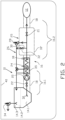
- FIG 2 there is shown another embodiment of the invention otherwise similar to that shown in the figure 1 , except that the return line 26 is here provided with a heat exchanger 35 coupled at its first side to the return line 26 and at its second side to the first line section 16.1 of the fuel supply line 16. This way gas returned to the tank 14 is cooled down by the liquefied gas flowing in the first line section.
- a marine vessel 40 which comprises an internal combustion piston engine 12 provided with a liquefied gas fuel feeding system 10 according to the invention.
Landscapes
- Engineering & Computer Science (AREA)
- Chemical & Material Sciences (AREA)
- Combustion & Propulsion (AREA)
- Mechanical Engineering (AREA)
- Chemical Kinetics & Catalysis (AREA)
- General Chemical & Material Sciences (AREA)
- Oil, Petroleum & Natural Gas (AREA)
- General Engineering & Computer Science (AREA)
- Ocean & Marine Engineering (AREA)
- Filling Or Discharging Of Gas Storage Vessels (AREA)
- Output Control And Ontrol Of Special Type Engine (AREA)
Description
- The present invention relates to a liquefied gas fuel feeding system for an internal combustion piston engine comprising: a tank configured to store fuel in cryogenic conditions, which when in use comprises a liquid gas space having a surface and an ullage space above the surface, a fuel supply line arranged to extend from the tank to the internal combustion piston engine, the fuel supply line comprising successively a first line section and a second line section, wherein the first line section is configured to receive liquefied gas from the tank, and comprises a liquid fuel pump configured to raise the pressure of liquefied gas to a predetermined first pressure and a gas evaporator configured to evaporate the liquefied gas at the first pressure; and wherein the second line section is configured to receive gaseous gas from the gas evaporator, the second line section comprising a gas valve unit arranged to the second line section and configured to open or close the flow connection between the gas evaporation system and the internal combustion piston engine.
- Natural gas as a fuel for internal combustion engines in marine vessels has become more common because of the environmental reasons since the combustion results are less harmful than for example those resulted in combustion of heavy or light fuel oil. At the same time the equipment for handling and regulating gas fuel is subjected to stringent safety regulations. Gaseous fuels are generally harmful to the environment and therefore any leakage to the atmosphere is undesired.
-
EP 2032428 B1 discloses a fuel system for a gas driven piston engine in a marine vessel, which gas is stored in at least one fuel storage tank in the vessel as liquefied gas. The fuel feeding system comprises a separate fuel feed tank in which the gas is in liquid phase and at elevated pressure. The gas is also in liquid phase in the fuel storage tank, in which, however, prevails only the hydrostatic pressure caused by the liquid gas. In this kind of fuel system situations may occur in which excess gas needs to be purged from the tank, and often that means admission of gas into the atmosphere. -
US 5127230 discloses an LNG (liquefied natural gas) delivery system for a gas powered vehicle. The system includes a pair of LNG high pressure fuel tanks from which fuel is delivered to an engine. The system comprises vent valves set to operate if the pressure in the tanks of the system exceeds an abnormally high pressure. During normal operation, instead of admitting gas into atmosphere, the system is configured to lead gas from a non-selected tank to be used in the engine if the pressure rises over a predetermined pressure. This is possible since the system includes a pair of similar high pressure tanks which in practise means that the system is somewhat complicated. - Document
CA2653643 A1 discloses a pressure control system comprising separate conduits for supplying liquefied gas and vapour from a cryogen space defined by a cryogenic storage tank. A first conduit can deliver liquefied gas to a use device through a heater and then a first flow controller. A second conduit can deliver vapour to the use device with flow therethrough controlled by a second flow controller. The first flow controller is not exposed to liquefied gas at cryogenic temperatures because it is located downstream from the heater. For automatic operation a pressure sensor measures pressure inside the cryogen space and the first and second flow controllers are independently operable to maintain the pressure inside the cryogen space within a predetermined range. - Document
US2013/104997 A1 discloses a liquefied gas fuel feeding system for an internal combustion piston engine comprising: a tank configured to store fuel in cryogenic conditions, which when in use comprises a liquid gas space (lower part) having a surface and an ullage space (upper part) above the surface; a fuel supply line (line before pump) arranged to extend from the tank to the internal combustion piston engine, the fuel supply line (line before pump) comprising successively a first line section (line before pump), and a second line section, wherein the first line section is configured to receive liquefied gas from the tank, and comprises a liquid fuel pump configured to raise the pressure of liquefied gas to a predetermined first pressure and a gas evaporator in the pump configured to evaporate the liquefied gas into gaseous form at the first pressure: and wherein the second line section is configured to receive gaseous gas from the gas evaporator, the second line section comprising a gas valve unit configured to open or close the flow connection between the gas evaporator and the internal combustion piston engine; wherein the liquefied gas fuel feeding system is provided with a return line extending from the second line section to the tank, the return line opening into the ullage space of the tank; and being provided with a first pressure relief valve configured to open when pressure in the second line section exceeds at a first set pressure. - An object of the invention is to provide a liquefied gas fuel feeding system in which the admission of the gas to the surroundings is minimized.
- Objects of the invention can be met substantially as is disclosed in the independent claims and in the other claims describing more details of different embodiments of the invention.
- A liquefied gas fuel feeding system for an internal combustion piston engine comprising: a tank configured to store fuel in cryogenic conditions, which when in use comprises a liquid gas space having a surface and an ullage space above the surface; a fuel supply line arranged to extend from the tank to the internal combustion piston engine, the fuel supply line comprising successively a first line section and a second line section, wherein the first line section is configured to receive liquefied gas from the tank, and comprises a liquid fuel pump configured to raise the pressure of liquefied gas to a predetermined first pressure and a gas evaporator configured to evaporate the liquefied gas at the first pressure; and wherein the second line section is configured to receive gaseous gas from the gas evaporator, the second line section comprising a gas valve unit arranged to the second line section and configured to open or close the flow connection between the gas evaporation system and the internal combustion piston engine; whereby the liquefied gas fuel feeding system is provided with a return line extending from the second line section to the tank, the return line opening into the ullage space of the tank and being provided with a first pressure relief valve configured to open when pressure in the second line section exceeds a first set pressure, wherein the liquefied gas fuel feeding system comprises a conduit configured to provide a flow connection between the second line section and the ullage space of the tank, and that the conduit is provided with a valve member, the conduit extends from the second line section, to the return line, to a location between the first pressure relief valve and the tank, which conduit is at least partly parallel to the first pressure relief valve and the valve member is parallel to the first pressure relief valve.
- According to an embodiment of the invention the tank is configured to contain the fuel only typically at less than 1MPa.
- According to an embodiment of the invention the tank is configured to store the fuel at about 100 - 400 kPa.
- According to the invention the liquefied gas fuel feeding system comprises a conduit configured to provide a flow connection between the second line section and the ullage space of the tank, the conduit being provided with a valve member.
- According to the invention the conduit extends from the second line section to the return line, to a location between the first pressure relief valve and the tank, which conduit is at least partly parallel to the first pressure relief valve and the valve member is parallel to the first pressure relief valve.
- According to an embodiment of the invention the return line is provided with a heat exchanger coupled at its first side to the return line and at its second side to the first line section of the fuel supply line.
- According to an embodiment of the invention the tank is provided with a second pressure relief valve and the first pressure relief valve is configured to open at a higher pressure than the second pressure relief valve.
- According to the invention a marine vessel comprises an internal combustion piston engine provided with a liquefied gas fuel feeding system according to any one of the claims 1-5.
- The exemplary embodiments of the invention presented in this patent application are not to be interpreted to pose limitations to the applicability of the appended claims. The verb "to comprise" is used in this patent application as an open limitation that does not exclude the existence of also unrecited features. The liquefied gas fuel feeding system according to the invention is applicable both for vessels carrying liquefied gas as cargo and for vessels using liquefied gas as fuel for gas consumers in the vessel. On LNG cargo vessels there may be additional compressors used for further pressurizing the fuel to be fed into engines.
- The features recited in depending claims are mutually freely combinable unless otherwise explicitly stated. The novel features which are considered as characteristic of the invention are set forth in particular in the appended claims.
- In the following, the invention will be described with reference to the accompanying exemplary, schematic drawings, in which
-
Figure 1 illustrates a liquefied gas fuel feeding system according to an embodiment of the invention, and -
Figure 2 illustrates a liquefied gas fuel feeding system according to another embodiment of the invention. -
Figure 1 depicts schematically a liquefied gasfuel feeding system 10 which is suitable for feeding gaseous fuel to an internalcombustion piston engine 12 for example in a land based or a marine vessel power plant. The liquefied gasfuel feeding system 10 for an internalcombustion piston engine 12 comprises atank 14. Thetank 14 is configured to store fuel in cryogenic conditions, which means that it is provided with suitable heat insulation. Also, the tank is configured to store the fuel only typically at a moderate pressure, say about 100 - 400 kPa, or at least below 1 MPa. Thus, when in use i.e. being filled with gas the tank, more precisely the tank inner space, comprises a liquid gas space 14.1 having a surface 14.2 and an ullage space 14.3 above the surface. - The gas
fuel feeding system 10 comprises further afuel supply line 16. Thefuel supply line 16 is arranged to extend from thetank 14 to the internalcombustion piston engine 12 such that the gas may be delivered to theengine 12 for use as its fuel. Thefuel supply line 16 is provided with anenclosure 18 which forms a double wall surrounding for the inner pipe and the components in which the gas is conveyed or processed between thetank 14 and theengine 12. Where thefuel supply line 16 is a pipe the enclosure is advantageously an outer pipe around the pipe. Theenclosure 18 may also comprise a cabinet 18' or alike in which certain auxiliary components such as amain gas valve 21, pressure regulators or pressure transmitter can be positioned. - The
fuel supply line 16 comprises successively a first line section 16.1 and a second line section 16.2, in which the first section is configured to handle liquefied gas and the second section is configure to handle gaseous gas. The first line section 16.1 is arranged to open into the liquid gas space 14.1 of thetank 14 from which it receives liquefied gas. The fuel supply line, more specifically the first line section comprises also aliquid fuel pump 20, which is configured to raise the pressure of liquefied gas to a level of predetermined first pressure. The first pressure level is such that it exceeds the required fuel feed pressure of theengine 12 added with the pressure losses in thefuel supply line 16. The first line section 16.1 is also provided with a shut-offvalve 22 arranged between thetank 14 and thepump 20 i.e. at the suction side of thepump 20. Further thefuel supply line 16 comprises agas evaporation system 24 configured to evaporate the liquefied gas into gaseous form and optionally to heat the evaporated gas to a desired temperature. Thegas evaporation system 24 comprises a heat transfer unit or units which are connectable to a suitable heat source such as a cooling system of theengine 12. The evaporation system may also be referred to as an evaporator. The evaporation of the gas in theevaporator 24 takes place at the first pressure. The second line section 16.2 starts from theevaporation system 24 and extends to theengine 12. Thus, the second line section 16.2 is configured to receive gaseous gas from thegas evaporator 24. The second line section 16.2 comprises a so calledgas valve unit 25, which is formed of the cabinet 18' and its components. Thegas valve unit 25 is arranged to the second line section 16.2 and comprises themain gas valve 21. Themain gas valve 21 is configured to open or close the flow connection between thegas evaporator 24 and the internalcombustion piston engine 12. - Further, the liquefied gas
fuel feeding system 16 is provided with areturn line 26 which is extending from the second line section 16.2 to thetank 14 such that thereturn line 26 is opening into the ullage space 14.3 of thetank 14. The return line is provided with a firstpressure relief valve 28. The first pressure relief valve is set to open at a first set pressure which is more than the first pressure level. This way, in case the pressure of the gas in the second line section 16.2 of thefuel supply line 16 exceeds the first set pressure, therelief valve 28 opens and the pressure in thefuel supply line 16 is decreased. The excess gas purged from thefuel supply line 16 is directed via thefirst return line 26 back to thetank 12. The excess gas is introduced into the ullage space 14.3 of the tank, which has a substantially large volume such that the excess gas introduced into the tank raises the pressure in thetank 14 only moderately. - In the embodiment of the
figure 1 thereturn line 26 is provided with acheck valve 36 as an additional and optional feature. The check valve is configured to allow gas flow in the direction towards thetank 14. This way the pressure changes in thetank 14 are not received by thereturn line 26. Thus, if asingle tank 14 is provided with more than one parallel liquefied gas fuel feeding system (not shown) thecheck valve 36 isolates the systems from each other. - It is also conceivable to connect other gas sources, from which gas needs to be withdrawn, to the
return line 26. In thefigure 1 thepump 20 is connected to the return line optionally for discharging vent gas from the pump to thetank 14. As is depicted by a dotted line in thefigure 1 , the liquefied gasfuel feeding system 10 comprises a conduit 30' which is configured to provide a third flow connection between thepump 20 and the ullage space 14.3 of thetank 14. The conduit 30' is provided with a valve member 32'. The valve member 32' can be opened and closed manually or it can be connected to a control system which is configured to open the valve when certain predetermined criteria is met. - By means of the present invention any sudden increase of the pressure, regardless of the cause of such increase, of the gaseous gas causes the
pressure relief valve 28 to open and the gas flow through thepressure relief valve 28 to return to thetank 14. The pressure in the tank is considerably lower than the gas pressure in the second line section 16.2, which makes it possible to route the gas back to thetank 14. This way, practically no gas is admitted to the atmosphere. - The tank is provided with a second
pressure relief valve 34 by means of which it is ensured that the pressure in the tank cannot raise too high. However, when theengine 12 is running the gas consumption is so high that the pressure in thetank 14 will not normally raise too high even if some gas would be introduced back to thetank 14 via thereturn line 26 or the conduit 30'. The firstpressure relief valve 28 is configured to open at a higher pressure than the secondpressure relief valve 34, such that no damage can be caused to the tank structure. - According to the invention the liquefied gas
fuel feeding system 10 comprises aconduit 30 which is configured to provide a second flow connection between the second line section 16.2 of the liquefied gasfuel feeding system 16 and the ullage space 14.3 of thetank 14. Theconduit 30 is provided with avalve member 32. The valve member can be opened and closed manually or it can be connected to a control system which is configured to open the valve when certain predetermined criteria is met. By means of theconduit 30 and thevalve member 32 the gas pressure in thefuel supply line 16 can be safely relieved to the tank for example for servicing the gas fuel feeding system. In the embodiment of thefigure 1 theconduit 30 extends from the second line section 16.2, to a location between the coupling position of thereturn line 26 and thetank 14, to thereturn line 26 downstream the firstpressure relief valve 28. - In the
figure 2 there is shown another embodiment of the invention otherwise similar to that shown in thefigure 1 , except that thereturn line 26 is here provided with aheat exchanger 35 coupled at its first side to thereturn line 26 and at its second side to the first line section 16.1 of thefuel supply line 16. This way gas returned to thetank 14 is cooled down by the liquefied gas flowing in the first line section. In thefigure 2 there is also shown amarine vessel 40 which comprises an internalcombustion piston engine 12 provided with a liquefied gasfuel feeding system 10 according to the invention.
Claims (5)
- A liquefied gas fuel feeding system (10) for an internal combustion piston engine (12) comprising:a tank (14) configured to store fuel in cryogenic conditions, which when in use comprises a liquid gas space (14.1) having a surface (14.2) and an ullage space (14.3) above the surface (14.2);a fuel supply line (16) arranged to extend from the tank (14) to the internal combustion piston engine (12), the fuel supply line (16) comprising successively a first line section (16.1) and a second line section 16.2), wherein the first line section (16.1) is configured to receive liquefied gas from the tank (14), and comprises a liquid fuel pump (20) configured to raise the pressure of liquefied gas to a predetermined first pressure and a gas evaporator (24) configured to evaporate the liquefied gas into gaseous form at the first pressure; andwherein the second line section (16.2) is configured to receive gaseous gas from the gas evaporator (24), the second line section (16.2) comprising a gas valve unit (25) configured to open or close the flow connection between the gas evaporator (24) and the internal combustion piston engine (12);the liquefied gas fuel feeding system (10) is provided with a return line (26) extending from the second line section (16.2) to the tank (14), the return line (26) opening into the ullage space (14.3) of the tank (14) and being provided with a first pressure relief valve (28) configured to open when pressure in the second line section (16.2) exceeds a first set pressure, characterized in that,the liquefied gas fuel feeding system (10) comprises a conduit (30) configured to provide a flow connection between the second line section (16.2) and the ullage space of the tank (14), and that the conduit (30) is provided with a valve member (32), the conduit (30) extends from the second line section (16.2), to the return line (26), to a location between the first pressure relief valve (28) and the tank (14), which conduit (30) is at least partly parallel to the first pressure relief valve (28) and the valve member (32) is parallel to the first pressure relief valve (28).
- The liquefied gas fuel feeding system (10) according to claim 1, characterized in that the return line (26) is provided with a heat exchanger (35) coupled at its first side to the return line (26) and at its second side to the first line section (16.1) of the fuel supply line (16).
- The liquefied gas fuel feeding system (10) according to claim 1, characterized in that the tank (14) is provided with a second pressure relief valve (34) and that the first pressure relief valve (28) is configured to open at a higher pressure than the second pressure relief valve (34).
- The liquefied gas fuel feeding system (10) according to claim 1, characterized in that the return line (26) is provided with a check valve (36).
- A marine vessel (40) comprising an internal combustion piston engine (12) provided with a liquefied gas fuel feeding system (10) according to any one of the preceding claims.
Applications Claiming Priority (1)
| Application Number | Priority Date | Filing Date | Title |
|---|---|---|---|
| PCT/EP2017/060796 WO2018202313A1 (en) | 2017-05-05 | 2017-05-05 | A liquefied gas fuel feeding system and a marine vessel |
Publications (2)
| Publication Number | Publication Date |
|---|---|
| EP3619418A1 EP3619418A1 (en) | 2020-03-11 |
| EP3619418B1 true EP3619418B1 (en) | 2023-07-19 |
Family
ID=58671679
Family Applications (1)
| Application Number | Title | Priority Date | Filing Date |
|---|---|---|---|
| EP17721685.0A Active EP3619418B1 (en) | 2017-05-05 | 2017-05-05 | A liquefied gas fuel feeding system and a marine vessel |
Country Status (4)
| Country | Link |
|---|---|
| EP (1) | EP3619418B1 (en) |
| KR (1) | KR102355332B1 (en) |
| CN (1) | CN110582632B (en) |
| WO (1) | WO2018202313A1 (en) |
Families Citing this family (7)
| Publication number | Priority date | Publication date | Assignee | Title |
|---|---|---|---|---|
| WO2021095948A1 (en) | 2019-11-15 | 2021-05-20 | 대우조선해양 주식회사 | System and method for supplying fuel for ship |
| CN111392019B (en) * | 2020-03-27 | 2022-04-08 | 大连船舶重工集团有限公司 | Clean ship power system who discharges |
| CN113561763A (en) * | 2020-04-28 | 2021-10-29 | 未势能源科技有限公司 | Fuel processing unit and fuel storage and supply system with same |
| CN112696289B (en) * | 2020-12-28 | 2024-07-26 | 大连船舶重工集团有限公司 | A marine liquid ammonia fuel supply and fuel recovery system |
| EP4285013B1 (en) * | 2021-01-27 | 2025-03-26 | Wärtsilä Services Switzerland Ltd | An assembly for direct injection of gaseous fuel in a cylinder of a two-stroke internal combustion piston engine and a two-stroke internal com-bustion piston engine |
| WO2022194346A1 (en) | 2021-03-16 | 2022-09-22 | Wärtsilä Gas Solutions Norway AS | A liquefied fuel discharge assembly in a storage tank |
| CN115478959B (en) * | 2021-06-15 | 2025-05-23 | 南通中集能源装备有限公司 | Liquid fuel delivery mechanism and ship |
Citations (1)
| Publication number | Priority date | Publication date | Assignee | Title |
|---|---|---|---|---|
| US20130104997A1 (en) * | 2009-03-30 | 2013-05-02 | Westport Power Inc. | Method And System For Controlling Fluid Flow From A Storage Tank Through A Supply Line To An End User |
Family Cites Families (9)
| Publication number | Priority date | Publication date | Assignee | Title |
|---|---|---|---|---|
| US5127230A (en) | 1991-05-17 | 1992-07-07 | Minnesota Valley Engineering, Inc. | LNG delivery system for gas powered vehicles |
| US5771946A (en) * | 1992-12-07 | 1998-06-30 | Chicago Bridge & Iron Technical Services Company | Method and apparatus for fueling vehicles with liquefied cryogenic fuel |
| JP4570130B2 (en) * | 2004-04-23 | 2010-10-27 | 岩谷産業株式会社 | Equipment-linked low temperature liquefied gas supply equipment |
| FI122137B (en) | 2006-06-27 | 2011-09-15 | Waertsilae Finland Oy | A fuel system for a gas-powered vessel |
| CA2653643C (en) * | 2009-02-26 | 2010-08-31 | Westport Power Inc. | Pressure control system and method |
| KR101386543B1 (en) * | 2012-10-24 | 2014-04-18 | 대우조선해양 주식회사 | System for treating boil-off gas for a ship |
| WO2014091061A1 (en) * | 2012-12-14 | 2014-06-19 | Wärtsilä Finland Oy | Method of starting gas delivery from a liquefied gas fuel system to a gas operated engine and a liquefied gas fuel system for a gas operated engine |
| KR101290430B1 (en) * | 2013-04-24 | 2013-07-26 | 현대중공업 주식회사 | A fuel gas supply system of liquefied natural gas |
| EP3356172B1 (en) * | 2015-10-02 | 2019-08-21 | Volvo Truck Corporation | A gas tank arrangement for a dual fuel internal combustion engine |
-
2017
- 2017-05-05 CN CN201780090361.1A patent/CN110582632B/en active Active
- 2017-05-05 WO PCT/EP2017/060796 patent/WO2018202313A1/en not_active Ceased
- 2017-05-05 KR KR1020197034372A patent/KR102355332B1/en active Active
- 2017-05-05 EP EP17721685.0A patent/EP3619418B1/en active Active
Patent Citations (1)
| Publication number | Priority date | Publication date | Assignee | Title |
|---|---|---|---|---|
| US20130104997A1 (en) * | 2009-03-30 | 2013-05-02 | Westport Power Inc. | Method And System For Controlling Fluid Flow From A Storage Tank Through A Supply Line To An End User |
Also Published As
| Publication number | Publication date |
|---|---|
| KR102355332B1 (en) | 2022-01-24 |
| KR20200003838A (en) | 2020-01-10 |
| EP3619418A1 (en) | 2020-03-11 |
| CN110582632A (en) | 2019-12-17 |
| CN110582632B (en) | 2022-02-18 |
| WO2018202313A1 (en) | 2018-11-08 |
Similar Documents
| Publication | Publication Date | Title |
|---|---|---|
| EP3619418B1 (en) | A liquefied gas fuel feeding system and a marine vessel | |
| EP2212186B1 (en) | Method and operating system for operating a lng fuelled marine vessel | |
| US9771886B2 (en) | Method and system for delivering a gaseous fuel into the air intake system of an internal combustion engine | |
| EP2989370B1 (en) | Liquid natural gas cooling on the fly | |
| CN102656084B (en) | An lng fuel tank system for at least one gas engine used for ship propulsion | |
| US9897055B2 (en) | Method and system for delivering a gaseous fuel into the air intake system of an internal combustion engine | |
| KR101588663B1 (en) | Device for supplying fuel gas in ships | |
| US11155359B2 (en) | Aircraft fuel tank pressurization systems and methods | |
| US11613175B2 (en) | Indoor safety device, a liquefied fuel gas system and a vehicle | |
| US20140137572A1 (en) | Natural Gas Vehicle Vented Gas Capture System | |
| US20190137038A1 (en) | Hydrogen filling station with liquid hydrogen | |
| KR101505796B1 (en) | Venting apparatus for engine and fuel gas supply system in ships | |
| KR101710997B1 (en) | Loading device for lng | |
| KR101571417B1 (en) | Venting apparatus for ships | |
| US20090095153A1 (en) | Natural gas recovery system and method | |
| CN110462278B (en) | Liquefied gas tank device and method of operating a liquefied gas tank device | |
| US10415509B2 (en) | Cooling system for cryogenic fuel delivery components | |
| CN111386395A (en) | Mobile container-tank module | |
| RU165208U1 (en) | TANK CRYOGENIC FUEL VEHICLE OPERATING ON LIQUEFIED NATURAL GAS | |
| KR102710835B1 (en) | Fuel gas supply system and ship including the same | |
| KR102561802B1 (en) | High pressure pump system and vessel including the same, and control method of high pressure pump system | |
| HK40029578A (en) | Mobile container-tank module | |
| KR20170116656A (en) | fire prevention apparatus of gas supply system |
Legal Events
| Date | Code | Title | Description |
|---|---|---|---|
| STAA | Information on the status of an ep patent application or granted ep patent |
Free format text: STATUS: UNKNOWN |
|
| STAA | Information on the status of an ep patent application or granted ep patent |
Free format text: STATUS: THE INTERNATIONAL PUBLICATION HAS BEEN MADE |
|
| PUAI | Public reference made under article 153(3) epc to a published international application that has entered the european phase |
Free format text: ORIGINAL CODE: 0009012 |
|
| STAA | Information on the status of an ep patent application or granted ep patent |
Free format text: STATUS: REQUEST FOR EXAMINATION WAS MADE |
|
| 17P | Request for examination filed |
Effective date: 20191015 |
|
| AK | Designated contracting states |
Kind code of ref document: A1 Designated state(s): AL AT BE BG CH CY CZ DE DK EE ES FI FR GB GR HR HU IE IS IT LI LT LU LV MC MK MT NL NO PL PT RO RS SE SI SK SM TR |
|
| AX | Request for extension of the european patent |
Extension state: BA ME |
|
| DAV | Request for validation of the european patent (deleted) | ||
| DAX | Request for extension of the european patent (deleted) | ||
| STAA | Information on the status of an ep patent application or granted ep patent |
Free format text: STATUS: EXAMINATION IS IN PROGRESS |
|
| 17Q | First examination report despatched |
Effective date: 20201210 |
|
| GRAP | Despatch of communication of intention to grant a patent |
Free format text: ORIGINAL CODE: EPIDOSNIGR1 |
|
| STAA | Information on the status of an ep patent application or granted ep patent |
Free format text: STATUS: GRANT OF PATENT IS INTENDED |
|
| INTG | Intention to grant announced |
Effective date: 20230207 |
|
| GRAS | Grant fee paid |
Free format text: ORIGINAL CODE: EPIDOSNIGR3 |
|
| GRAA | (expected) grant |
Free format text: ORIGINAL CODE: 0009210 |
|
| STAA | Information on the status of an ep patent application or granted ep patent |
Free format text: STATUS: THE PATENT HAS BEEN GRANTED |
|
| AK | Designated contracting states |
Kind code of ref document: B1 Designated state(s): AL AT BE BG CH CY CZ DE DK EE ES FI FR GB GR HR HU IE IS IT LI LT LU LV MC MK MT NL NO PL PT RO RS SE SI SK SM TR |
|
| REG | Reference to a national code |
Ref country code: GB Ref legal event code: FG4D |
|
| REG | Reference to a national code |
Ref country code: CH Ref legal event code: EP |
|
| REG | Reference to a national code |
Ref country code: DE Ref legal event code: R096 Ref document number: 602017071446 Country of ref document: DE |
|
| REG | Reference to a national code |
Ref country code: IE Ref legal event code: FG4D |
|
| REG | Reference to a national code |
Ref country code: NO Ref legal event code: T2 Effective date: 20230719 |
|
| REG | Reference to a national code |
Ref country code: NL Ref legal event code: FP |
|
| REG | Reference to a national code |
Ref country code: LT Ref legal event code: MG9D |
|
| REG | Reference to a national code |
Ref country code: AT Ref legal event code: MK05 Ref document number: 1589712 Country of ref document: AT Kind code of ref document: T Effective date: 20230719 |
|
| PG25 | Lapsed in a contracting state [announced via postgrant information from national office to epo] |
Ref country code: GR Free format text: LAPSE BECAUSE OF FAILURE TO SUBMIT A TRANSLATION OF THE DESCRIPTION OR TO PAY THE FEE WITHIN THE PRESCRIBED TIME-LIMIT Effective date: 20231020 |
|
| PG25 | Lapsed in a contracting state [announced via postgrant information from national office to epo] |
Ref country code: IS Free format text: LAPSE BECAUSE OF FAILURE TO SUBMIT A TRANSLATION OF THE DESCRIPTION OR TO PAY THE FEE WITHIN THE PRESCRIBED TIME-LIMIT Effective date: 20231119 |
|
| PG25 | Lapsed in a contracting state [announced via postgrant information from national office to epo] |
Ref country code: SE Free format text: LAPSE BECAUSE OF FAILURE TO SUBMIT A TRANSLATION OF THE DESCRIPTION OR TO PAY THE FEE WITHIN THE PRESCRIBED TIME-LIMIT Effective date: 20230719 Ref country code: RS Free format text: LAPSE BECAUSE OF FAILURE TO SUBMIT A TRANSLATION OF THE DESCRIPTION OR TO PAY THE FEE WITHIN THE PRESCRIBED TIME-LIMIT Effective date: 20230719 Ref country code: PT Free format text: LAPSE BECAUSE OF FAILURE TO SUBMIT A TRANSLATION OF THE DESCRIPTION OR TO PAY THE FEE WITHIN THE PRESCRIBED TIME-LIMIT Effective date: 20231120 Ref country code: LV Free format text: LAPSE BECAUSE OF FAILURE TO SUBMIT A TRANSLATION OF THE DESCRIPTION OR TO PAY THE FEE WITHIN THE PRESCRIBED TIME-LIMIT Effective date: 20230719 Ref country code: LT Free format text: LAPSE BECAUSE OF FAILURE TO SUBMIT A TRANSLATION OF THE DESCRIPTION OR TO PAY THE FEE WITHIN THE PRESCRIBED TIME-LIMIT Effective date: 20230719 Ref country code: IS Free format text: LAPSE BECAUSE OF FAILURE TO SUBMIT A TRANSLATION OF THE DESCRIPTION OR TO PAY THE FEE WITHIN THE PRESCRIBED TIME-LIMIT Effective date: 20231119 Ref country code: HR Free format text: LAPSE BECAUSE OF FAILURE TO SUBMIT A TRANSLATION OF THE DESCRIPTION OR TO PAY THE FEE WITHIN THE PRESCRIBED TIME-LIMIT Effective date: 20230719 Ref country code: GR Free format text: LAPSE BECAUSE OF FAILURE TO SUBMIT A TRANSLATION OF THE DESCRIPTION OR TO PAY THE FEE WITHIN THE PRESCRIBED TIME-LIMIT Effective date: 20231020 Ref country code: FI Free format text: LAPSE BECAUSE OF FAILURE TO SUBMIT A TRANSLATION OF THE DESCRIPTION OR TO PAY THE FEE WITHIN THE PRESCRIBED TIME-LIMIT Effective date: 20230719 Ref country code: AT Free format text: LAPSE BECAUSE OF FAILURE TO SUBMIT A TRANSLATION OF THE DESCRIPTION OR TO PAY THE FEE WITHIN THE PRESCRIBED TIME-LIMIT Effective date: 20230719 |
|
| PG25 | Lapsed in a contracting state [announced via postgrant information from national office to epo] |
Ref country code: PL Free format text: LAPSE BECAUSE OF FAILURE TO SUBMIT A TRANSLATION OF THE DESCRIPTION OR TO PAY THE FEE WITHIN THE PRESCRIBED TIME-LIMIT Effective date: 20230719 |
|
| REG | Reference to a national code |
Ref country code: DE Ref legal event code: R097 Ref document number: 602017071446 Country of ref document: DE |
|
| PG25 | Lapsed in a contracting state [announced via postgrant information from national office to epo] |
Ref country code: ES Free format text: LAPSE BECAUSE OF FAILURE TO SUBMIT A TRANSLATION OF THE DESCRIPTION OR TO PAY THE FEE WITHIN THE PRESCRIBED TIME-LIMIT Effective date: 20230719 |
|
| PG25 | Lapsed in a contracting state [announced via postgrant information from national office to epo] |
Ref country code: SM Free format text: LAPSE BECAUSE OF FAILURE TO SUBMIT A TRANSLATION OF THE DESCRIPTION OR TO PAY THE FEE WITHIN THE PRESCRIBED TIME-LIMIT Effective date: 20230719 Ref country code: RO Free format text: LAPSE BECAUSE OF FAILURE TO SUBMIT A TRANSLATION OF THE DESCRIPTION OR TO PAY THE FEE WITHIN THE PRESCRIBED TIME-LIMIT Effective date: 20230719 Ref country code: ES Free format text: LAPSE BECAUSE OF FAILURE TO SUBMIT A TRANSLATION OF THE DESCRIPTION OR TO PAY THE FEE WITHIN THE PRESCRIBED TIME-LIMIT Effective date: 20230719 Ref country code: EE Free format text: LAPSE BECAUSE OF FAILURE TO SUBMIT A TRANSLATION OF THE DESCRIPTION OR TO PAY THE FEE WITHIN THE PRESCRIBED TIME-LIMIT Effective date: 20230719 Ref country code: DK Free format text: LAPSE BECAUSE OF FAILURE TO SUBMIT A TRANSLATION OF THE DESCRIPTION OR TO PAY THE FEE WITHIN THE PRESCRIBED TIME-LIMIT Effective date: 20230719 Ref country code: CZ Free format text: LAPSE BECAUSE OF FAILURE TO SUBMIT A TRANSLATION OF THE DESCRIPTION OR TO PAY THE FEE WITHIN THE PRESCRIBED TIME-LIMIT Effective date: 20230719 Ref country code: SK Free format text: LAPSE BECAUSE OF FAILURE TO SUBMIT A TRANSLATION OF THE DESCRIPTION OR TO PAY THE FEE WITHIN THE PRESCRIBED TIME-LIMIT Effective date: 20230719 |
|
| PLBE | No opposition filed within time limit |
Free format text: ORIGINAL CODE: 0009261 |
|
| STAA | Information on the status of an ep patent application or granted ep patent |
Free format text: STATUS: NO OPPOSITION FILED WITHIN TIME LIMIT |
|
| 26N | No opposition filed |
Effective date: 20240422 |
|
| PG25 | Lapsed in a contracting state [announced via postgrant information from national office to epo] |
Ref country code: SI Free format text: LAPSE BECAUSE OF FAILURE TO SUBMIT A TRANSLATION OF THE DESCRIPTION OR TO PAY THE FEE WITHIN THE PRESCRIBED TIME-LIMIT Effective date: 20230719 |
|
| PG25 | Lapsed in a contracting state [announced via postgrant information from national office to epo] |
Ref country code: BG Free format text: LAPSE BECAUSE OF FAILURE TO SUBMIT A TRANSLATION OF THE DESCRIPTION OR TO PAY THE FEE WITHIN THE PRESCRIBED TIME-LIMIT Effective date: 20230719 |
|
| PG25 | Lapsed in a contracting state [announced via postgrant information from national office to epo] |
Ref country code: BG Free format text: LAPSE BECAUSE OF FAILURE TO SUBMIT A TRANSLATION OF THE DESCRIPTION OR TO PAY THE FEE WITHIN THE PRESCRIBED TIME-LIMIT Effective date: 20230719 |
|
| REG | Reference to a national code |
Ref country code: CH Ref legal event code: PL |
|
| PG25 | Lapsed in a contracting state [announced via postgrant information from national office to epo] |
Ref country code: MC Free format text: LAPSE BECAUSE OF FAILURE TO SUBMIT A TRANSLATION OF THE DESCRIPTION OR TO PAY THE FEE WITHIN THE PRESCRIBED TIME-LIMIT Effective date: 20230719 |
|
| PG25 | Lapsed in a contracting state [announced via postgrant information from national office to epo] |
Ref country code: LU Free format text: LAPSE BECAUSE OF NON-PAYMENT OF DUE FEES Effective date: 20240505 |
|
| PG25 | Lapsed in a contracting state [announced via postgrant information from national office to epo] |
Ref country code: MC Free format text: LAPSE BECAUSE OF FAILURE TO SUBMIT A TRANSLATION OF THE DESCRIPTION OR TO PAY THE FEE WITHIN THE PRESCRIBED TIME-LIMIT Effective date: 20230719 Ref country code: LU Free format text: LAPSE BECAUSE OF NON-PAYMENT OF DUE FEES Effective date: 20240505 Ref country code: CH Free format text: LAPSE BECAUSE OF NON-PAYMENT OF DUE FEES Effective date: 20240531 |
|
| REG | Reference to a national code |
Ref country code: BE Ref legal event code: MM Effective date: 20240531 |
|
| PG25 | Lapsed in a contracting state [announced via postgrant information from national office to epo] |
Ref country code: IE Free format text: LAPSE BECAUSE OF NON-PAYMENT OF DUE FEES Effective date: 20240505 |
|
| PG25 | Lapsed in a contracting state [announced via postgrant information from national office to epo] |
Ref country code: BE Free format text: LAPSE BECAUSE OF NON-PAYMENT OF DUE FEES Effective date: 20240531 |
|
| PGFP | Annual fee paid to national office [announced via postgrant information from national office to epo] |
Ref country code: NL Payment date: 20250521 Year of fee payment: 9 |
|
| PGFP | Annual fee paid to national office [announced via postgrant information from national office to epo] |
Ref country code: DE Payment date: 20250521 Year of fee payment: 9 |
|
| PGFP | Annual fee paid to national office [announced via postgrant information from national office to epo] |
Ref country code: GB Payment date: 20250527 Year of fee payment: 9 |
|
| PGFP | Annual fee paid to national office [announced via postgrant information from national office to epo] |
Ref country code: NO Payment date: 20250523 Year of fee payment: 9 |
|
| PGFP | Annual fee paid to national office [announced via postgrant information from national office to epo] |
Ref country code: IT Payment date: 20250527 Year of fee payment: 9 |
|
| PGFP | Annual fee paid to national office [announced via postgrant information from national office to epo] |
Ref country code: FR Payment date: 20250528 Year of fee payment: 9 |
|
| PG25 | Lapsed in a contracting state [announced via postgrant information from national office to epo] |
Ref country code: CY Free format text: LAPSE BECAUSE OF FAILURE TO SUBMIT A TRANSLATION OF THE DESCRIPTION OR TO PAY THE FEE WITHIN THE PRESCRIBED TIME-LIMIT; INVALID AB INITIO Effective date: 20170505 |
|
| PG25 | Lapsed in a contracting state [announced via postgrant information from national office to epo] |
Ref country code: HU Free format text: LAPSE BECAUSE OF FAILURE TO SUBMIT A TRANSLATION OF THE DESCRIPTION OR TO PAY THE FEE WITHIN THE PRESCRIBED TIME-LIMIT; INVALID AB INITIO Effective date: 20170505 |