EP3619046B1 - Improvements in or relating to printers - Google Patents
Improvements in or relating to printers Download PDFInfo
- Publication number
- EP3619046B1 EP3619046B1 EP18723921.5A EP18723921A EP3619046B1 EP 3619046 B1 EP3619046 B1 EP 3619046B1 EP 18723921 A EP18723921 A EP 18723921A EP 3619046 B1 EP3619046 B1 EP 3619046B1
- Authority
- EP
- European Patent Office
- Prior art keywords
- printer
- message
- speed
- printed
- Prior art date
- Legal status (The legal status is an assumption and is not a legal conclusion. Google has not performed a legal analysis and makes no representation as to the accuracy of the status listed.)
- Active
Links
Images


Classifications
-
- B—PERFORMING OPERATIONS; TRANSPORTING
- B41—PRINTING; LINING MACHINES; TYPEWRITERS; STAMPS
- B41J—TYPEWRITERS; SELECTIVE PRINTING MECHANISMS, i.e. MECHANISMS PRINTING OTHERWISE THAN FROM A FORME; CORRECTION OF TYPOGRAPHICAL ERRORS
- B41J29/00—Details of, or accessories for, typewriters or selective printing mechanisms not otherwise provided for
- B41J29/38—Drives, motors, controls or automatic cut-off devices for the entire printing mechanism
- B41J29/393—Devices for controlling or analysing the entire machine ; Controlling or analysing mechanical parameters involving printing of test patterns
-
- B—PERFORMING OPERATIONS; TRANSPORTING
- B41—PRINTING; LINING MACHINES; TYPEWRITERS; STAMPS
- B41J—TYPEWRITERS; SELECTIVE PRINTING MECHANISMS, i.e. MECHANISMS PRINTING OTHERWISE THAN FROM A FORME; CORRECTION OF TYPOGRAPHICAL ERRORS
- B41J25/00—Actions or mechanisms not otherwise provided for
- B41J25/001—Mechanisms for bodily moving print heads or carriages parallel to the paper surface
-
- B—PERFORMING OPERATIONS; TRANSPORTING
- B41—PRINTING; LINING MACHINES; TYPEWRITERS; STAMPS
- B41J—TYPEWRITERS; SELECTIVE PRINTING MECHANISMS, i.e. MECHANISMS PRINTING OTHERWISE THAN FROM A FORME; CORRECTION OF TYPOGRAPHICAL ERRORS
- B41J13/00—Devices or arrangements of selective printing mechanisms, e.g. ink-jet printers or thermal printers, specially adapted for supporting or handling copy material in short lengths, e.g. sheets
- B41J13/0009—Devices or arrangements of selective printing mechanisms, e.g. ink-jet printers or thermal printers, specially adapted for supporting or handling copy material in short lengths, e.g. sheets control of the transport of the copy material
-
- B—PERFORMING OPERATIONS; TRANSPORTING
- B41—PRINTING; LINING MACHINES; TYPEWRITERS; STAMPS
- B41J—TYPEWRITERS; SELECTIVE PRINTING MECHANISMS, i.e. MECHANISMS PRINTING OTHERWISE THAN FROM A FORME; CORRECTION OF TYPOGRAPHICAL ERRORS
- B41J2/00—Typewriters or selective printing mechanisms characterised by the printing or marking process for which they are designed
- B41J2/005—Typewriters or selective printing mechanisms characterised by the printing or marking process for which they are designed characterised by bringing liquid or particles selectively into contact with a printing material
- B41J2/01—Ink jet
- B41J2/015—Ink jet characterised by the jet generation process
- B41J2/02—Ink jet characterised by the jet generation process generating a continuous ink jet
-
- B—PERFORMING OPERATIONS; TRANSPORTING
- B41—PRINTING; LINING MACHINES; TYPEWRITERS; STAMPS
- B41J—TYPEWRITERS; SELECTIVE PRINTING MECHANISMS, i.e. MECHANISMS PRINTING OTHERWISE THAN FROM A FORME; CORRECTION OF TYPOGRAPHICAL ERRORS
- B41J2/00—Typewriters or selective printing mechanisms characterised by the printing or marking process for which they are designed
- B41J2/005—Typewriters or selective printing mechanisms characterised by the printing or marking process for which they are designed characterised by bringing liquid or particles selectively into contact with a printing material
- B41J2/01—Ink jet
- B41J2/015—Ink jet characterised by the jet generation process
- B41J2/02—Ink jet characterised by the jet generation process generating a continuous ink jet
- B41J2/03—Ink jet characterised by the jet generation process generating a continuous ink jet by pressure
-
- B—PERFORMING OPERATIONS; TRANSPORTING
- B41—PRINTING; LINING MACHINES; TYPEWRITERS; STAMPS
- B41J—TYPEWRITERS; SELECTIVE PRINTING MECHANISMS, i.e. MECHANISMS PRINTING OTHERWISE THAN FROM A FORME; CORRECTION OF TYPOGRAPHICAL ERRORS
- B41J2/00—Typewriters or selective printing mechanisms characterised by the printing or marking process for which they are designed
- B41J2/005—Typewriters or selective printing mechanisms characterised by the printing or marking process for which they are designed characterised by bringing liquid or particles selectively into contact with a printing material
- B41J2/01—Ink jet
- B41J2/015—Ink jet characterised by the jet generation process
- B41J2/04—Ink jet characterised by the jet generation process generating single droplets or particles on demand
- B41J2/045—Ink jet characterised by the jet generation process generating single droplets or particles on demand by pressure, e.g. electromechanical transducers
- B41J2/04501—Control methods or devices therefor, e.g. driver circuits, control circuits
- B41J2/04508—Control methods or devices therefor, e.g. driver circuits, control circuits aiming at correcting other parameters
-
- B—PERFORMING OPERATIONS; TRANSPORTING
- B41—PRINTING; LINING MACHINES; TYPEWRITERS; STAMPS
- B41J—TYPEWRITERS; SELECTIVE PRINTING MECHANISMS, i.e. MECHANISMS PRINTING OTHERWISE THAN FROM A FORME; CORRECTION OF TYPOGRAPHICAL ERRORS
- B41J2/00—Typewriters or selective printing mechanisms characterised by the printing or marking process for which they are designed
- B41J2/005—Typewriters or selective printing mechanisms characterised by the printing or marking process for which they are designed characterised by bringing liquid or particles selectively into contact with a printing material
- B41J2/01—Ink jet
- B41J2/21—Ink jet for multi-colour printing
- B41J2/2132—Print quality control characterised by dot disposition, e.g. for reducing white stripes or banding
-
- B—PERFORMING OPERATIONS; TRANSPORTING
- B41—PRINTING; LINING MACHINES; TYPEWRITERS; STAMPS
- B41J—TYPEWRITERS; SELECTIVE PRINTING MECHANISMS, i.e. MECHANISMS PRINTING OTHERWISE THAN FROM A FORME; CORRECTION OF TYPOGRAPHICAL ERRORS
- B41J2/00—Typewriters or selective printing mechanisms characterised by the printing or marking process for which they are designed
- B41J2/005—Typewriters or selective printing mechanisms characterised by the printing or marking process for which they are designed characterised by bringing liquid or particles selectively into contact with a printing material
- B41J2/01—Ink jet
- B41J2/015—Ink jet characterised by the jet generation process
- B41J2/02—Ink jet characterised by the jet generation process generating a continuous ink jet
- B41J2002/022—Control methods or devices for continuous ink jet
Definitions
- This invention relates to a method of, and/or a system for, maintaining print quality. While the system has been devised for providing an indication of print quality in a continuous inkjet printer it will be appreciated that the invention is also applicable to other printing technologies.
- Continuous inkjet ('CIJ') printers are widely used to place identification codes on products.
- a CIJ printer includes a printer housing that contains a system for pressurising ink. Once pressurised, the ink is passed, via an ink feed line through a conduit, to a printhead. At the printhead the pressurised ink is passed through a nozzle to form an inkjet. A vibration or perturbation is applied to the inkjet causing the jet to break into a stream of droplets.
- the printer includes a charge electrode to charge selected droplets, and an electrostatic facility to deflect the charged droplets away from their original trajectory and onto a substrate. By controlling the amount of charge that is placed on droplets, the trajectories of those droplets can be controlled to form a printed image.
- a continuous inkjet printer is so termed because the printer forms a continuous stream of droplets irrespective of whether or not any particular droplet is to be used to print.
- the printer selects the drops to be used for printing by applying a charge to those drops, unprinted drops being allowed to continue, on the same trajectory as they were jetted from the nozzle, into a catcher or gutter.
- the unprinted drops collected in the gutter are returned from the printhead to the printer housing via a gutter line included in the same conduit as contains the pressurised ink feed line feeding ink to the printhead.
- Ink, together with entrained air, is generally returned to the printer housing under vacuum, the vacuum being generated by a pump in the gutter line.
- CIJ printers print characters and images broken into strokes, or swaths of drops which, when printed side-by-side, form the required image.
- a stroke of print is formed using a raster architecture which defines the number of drops and the print height of a stroke, the vertical slice of a bitmap that defines which drops in the stroke are to be printed, and the application of a raster algorithm that establishes the voltage required at the charge electrode to achieve the required charge on each drop.
- the operation of the printer can be synchronised to a moving substrate using a speed sensing device such as an encoder which provides an output in pulses in response to the movement of the production line or substrate. These pulses are received by the printer and used to synchronise the print output.
- the encoder increments a counter in the printer which is compared to a target count for the onset of a stroke and, when the two are equal, the stroke is printed.
- CIJ printers often include systems which compensate for the time it takes for the charged droplets to travel from the point at which they are charged, to the substrate. This is often termed time-of-flight.
- An effective time-of-flight system will not just make an adjustment for the start of a printed message (the first stroke), but it will continually make adjustments for subsequent strokes in a printed message - the faster the substrate speed, the more the time-of-flight system advances the start of the stroke.
- EP 2 644 384 is concerned with a CIJ printer that can determine an acceleration of a production line and use the acceleration to predict the required interval between raster strokes.
- the maximum speed of printing is dictated by the raster length and drop frequency. If the speed of the production line exceeds that at which strokes can be printed, then the onset of a stroke will be delayed until the previous stroke is printed. This results in the appearance of an elongated or stretched print on the substrate in the direction of movement of the line due to the fact that the substrate has moved further than intended from one stroke to the next.
- the stretching of the intended print is in effect a degradation of print quality, so it is usual to warn the user when this occurs.
- One way of establishing the need to provide this warning is to simply detect if the target encoder count, is less than the current encoder count; that is to say the stroke is late and therefore the print must have stretched.
- GB-A-2,398,447 discloses a method and apparatus in accordance with the precharacterizing portions of claims 1 and 7 respectively.
- the invention provides a method of regulating the operation of a printer printing in strokes on a substrate passing along a moving production line in a print direction, said method being characterised in that it includes a user of said printer defining an allowable amount of stretch in said print direction of a message to be printed by said printer.
- allowable amount of stretch is meant an allowable increase in length in the print direction of a message due to an increase in length in the print direction of gaps between successive strokes printed by the printer.
- a speed sensing facility giving an output representative of the speed of said moving production line, said method comprising defining, in units corresponding to the output of said speed sensing facility, target gaps between strokes in said print direction; defining an allowable stretch in said message; and comparing the outputs of stroke printing events of said speed sensing facility with said target gaps.
- the output of said speed sensing facility is provided as encoder pulses and wherein said target gaps are defined in terms of pulses, said method comprising comparing the counts of encoder pulses of print stroke events with the counts representing said target gaps.
- said printer is provided with a print system into which a message to be printed is loaded, said method comprising programming said print system to determine said target count measures.
- said method further includes determining and storing a maximum difference between said outputs of stroke printing events of the speed sensing facility and said target gaps.
- Preferably said method further includes generating an alert in the event an actual amount of stretch exceeds the allowable amount of stretch.
- the invention provides a printer operable to print a message in strokes on a substrate passing in a print direction along a moving production line, wherein the printer is operable to receive an indication of an allowable increase in length in the print direction of a message due to an increase in length in the print direction of gaps between successive strokes printed by the printer, to receive an indication of a speed of movement in the print direction of a moving production line, to determine from the indication of the speed of movement of the moving production line whether an increase in length in the print direction of a message printed by the printer is greater than the allowable increase in length and, if so, to generate an alert.
- said printer comprises a continuous inkjet printer.
- a CIJ printer 5 is shown alongside a moving line 6 on which articles 7, constituting a substrate, are conveyed in the direction of arrow 8.
- a speed sensing facility such as encoder 9 is provided to output a sequence of pulses representative of the speed of the line 6.
- the CIJ printer 5 comprises a cabinet 10 and a printhead 11 positioned over the line 6 and connected to the cabinet 10 by an umbilical 12.
- the cabinet 10 contains the usual mechanical system 13 and electronics system 14 that enables the CIJ printer to operate in the known manner, the umbilical 12 circulating ink and make-up between the cabinet and the printhead in the known manner.
- a user interface 15 conventionally comprising a screen and a keyboard, is provided to allow data and instructions to be entered into the printer and line speed data is also entered into the electronics system 14 from the encoder 9.
- the invention provides a method which gives a more meaningful alert to a user that print quality has been affected by over-speed situations.
- the method allows the user to specify an amount of allowable elongation or stretching of a printed message before an alert is raised. Furthermore the user may also be informed of the amount of stretching that has actually been detected to assist with decision-making on how to deal with the alert.
- the user inputs an amount of allowable elongation or stretch via the user interface 15; this may be in units of distance or encoder-related counts and the value is stored in a register 20 in the electronics system 14 of the printer.
- the output signal from encoder 9 is entered and processed at 21, a step which may involve multiplication or division of the encoder frequency, and the resultant signal is then used to increment a counter 22 which represents the distance along the substrate.
- the message 23 to be printed on the substrate is loaded into print system 24, the print system analysing the message and establishing a series of charge or voltage values which constitute the vertical drop placements required for each stroke, along with target encoder count values for the horizontal positions of the starts of the strokes which are stored at 25. It will be appreciated that the spacing between strokes may not be constant but may vary according to the message which may contain segments at different pitches.
- the encoder counter 22 and the stroke target count 25 are continually compared/subtracted at step 26 and the result is presented to a comparator 27. If the encoder counter 22 is larger than the stroke target 25 by an amount greater than the allowable stretch entered at 20, then an alert is raised at step 28.
- the output of the subtract step 26 may also be fed into a peak detector 29 which records the maximum level of stretch observed since the value was last read by the electronics system 14.
- the value of peak detection may be used alongside the alert notification to give the user an indication of the actual stretch amount seen.
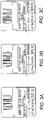
- the stretch referred to may be better understood by observing the line showing "SELL BY DATE” and the Date "APRIL 17".
- the date is shown at the correct spacing while in Figure 3B the spacing, though still acceptable, is stretched toward the edge of the label.
- Figure 3C indicates a print that has been stretched beyond an acceptable level and which would incur an alert as described herein.
- This solution may involve the use of a faster raster or possibly slowing the line speed, the method chosen depending on the nature of compromise that the user is willing to accept.
Landscapes
- Engineering & Computer Science (AREA)
- Quality & Reliability (AREA)
- Ink Jet (AREA)
- Accessory Devices And Overall Control Thereof (AREA)
Description
- This invention relates to a method of, and/or a system for, maintaining print quality. While the system has been devised for providing an indication of print quality in a continuous inkjet printer it will be appreciated that the invention is also applicable to other printing technologies.
- Continuous inkjet ('CIJ') printers are widely used to place identification codes on products. Typically a CIJ printer includes a printer housing that contains a system for pressurising ink. Once pressurised, the ink is passed, via an ink feed line through a conduit, to a printhead. At the printhead the pressurised ink is passed through a nozzle to form an inkjet. A vibration or perturbation is applied to the inkjet causing the jet to break into a stream of droplets.
- The printer includes a charge electrode to charge selected droplets, and an electrostatic facility to deflect the charged droplets away from their original trajectory and onto a substrate. By controlling the amount of charge that is placed on droplets, the trajectories of those droplets can be controlled to form a printed image.
- A continuous inkjet printer is so termed because the printer forms a continuous stream of droplets irrespective of whether or not any particular droplet is to be used to print. The printer selects the drops to be used for printing by applying a charge to those drops, unprinted drops being allowed to continue, on the same trajectory as they were jetted from the nozzle, into a catcher or gutter. The unprinted drops collected in the gutter are returned from the printhead to the printer housing via a gutter line included in the same conduit as contains the pressurised ink feed line feeding ink to the printhead. Ink, together with entrained air, is generally returned to the printer housing under vacuum, the vacuum being generated by a pump in the gutter line.
- CIJ printers print characters and images broken into strokes, or swaths of drops which, when printed side-by-side, form the required image.
- A stroke of print is formed using a raster architecture which defines the number of drops and the print height of a stroke, the vertical slice of a bitmap that defines which drops in the stroke are to be printed, and the application of a raster algorithm that establishes the voltage required at the charge electrode to achieve the required charge on each drop.
- The number of drops in a raster stroke, along with the frequency at which the drops are created, dictate how fast a message can be printed and this in turn dictates the maximum print speed on a production line.
- When the production line in running at less than the maximum print speed, there will be one or more unprinted drops between each succession of drops used to print a raster stroke. As the speed of the production line increases, the number of unprinted drops between each succession of drops used to print a raster stroke decreases, until at the maximum print speed, there are no unprinted drops between each succession of drops used to print a raster stroke.
- The operation of the printer can be synchronised to a moving substrate using a speed sensing device such as an encoder which provides an output in pulses in response to the movement of the production line or substrate. These pulses are received by the printer and used to synchronise the print output. In a typical printer application the encoder increments a counter in the printer which is compared to a target count for the onset of a stroke and, when the two are equal, the stroke is printed.
- In industrial marking and coding applications, it is generally the objective to print at the maximum rate possible for the technology used. For CIJ printers the maximum print rate is usually a compromise with print quality.
- CIJ printers often include systems which compensate for the time it takes for the charged droplets to travel from the point at which they are charged, to the substrate. This is often termed time-of-flight. An effective time-of-flight system will not just make an adjustment for the start of a printed message (the first stroke), but it will continually make adjustments for subsequent strokes in a printed message - the faster the substrate speed, the more the time-of-flight system advances the start of the stroke.
-
EP 2 644 384 is concerned with a CIJ printer that can determine an acceleration of a production line and use the acceleration to predict the required interval between raster strokes. - As outlined above, the maximum speed of printing is dictated by the raster length and drop frequency. If the speed of the production line exceeds that at which strokes can be printed, then the onset of a stroke will be delayed until the previous stroke is printed. This results in the appearance of an elongated or stretched print on the substrate in the direction of movement of the line due to the fact that the substrate has moved further than intended from one stroke to the next.
- The stretching of the intended print is in effect a degradation of print quality, so it is usual to warn the user when this occurs.
- One way of establishing the need to provide this warning is to simply detect if the target encoder count, is less than the current encoder count; that is to say the stroke is late and therefore the print must have stretched.
- When printing at any stroke rate, there will come a point when the encoder count is very close to the target encoder count to print the stroke, i.e. the stroke is just about to be printed. In this circumstance, if the time-of-flight system detects an increase in speed and advances the timing accordingly by advancing the encoder count, the stroke will be seen as being late and a stretch alert will be raised when this is not actually the case.
- When printing at or close to the maximum speed allowed by the raster, any slight increase in speed, as detected by the encoder, might cause this situation to occur, and therefore warn the user when the print quality has not significantly been affected, this being a nuisance to the user.
- Furthermore, since a print consists of many strokes, multiple alerts might be raised at a high rate which could overload software systems.
- It is an object of the invention to provide a method of regulating the use of a printer that will go at least some way in addressing the aforementioned problems; or which will at least offer a novel and useful choice.
-
GB-A-2,398,447 claims 1 and 7 respectively. - Accordingly, in one aspect, the invention provides a method of regulating the operation of a printer printing in strokes on a substrate passing along a moving production line in a print direction, said method being characterised in that it includes a user of said printer defining an allowable amount of stretch in said print direction of a message to be printed by said printer.
- By "allowable amount of stretch" is meant an allowable increase in length in the print direction of a message due to an increase in length in the print direction of gaps between successive strokes printed by the printer.
- Preferably a speed sensing facility is provided giving an output representative of the speed of said moving production line, said method comprising defining, in units corresponding to the output of said speed sensing facility, target gaps between strokes in said print direction; defining an allowable stretch in said message; and comparing the outputs of stroke printing events of said speed sensing facility with said target gaps.
- Preferably the output of said speed sensing facility is provided as encoder pulses and wherein said target gaps are defined in terms of pulses, said method comprising comparing the counts of encoder pulses of print stroke events with the counts representing said target gaps.
- Preferably said printer is provided with a print system into which a message to be printed is loaded, said method comprising programming said print system to determine said target count measures.
- Preferably said method further includes determining and storing a maximum difference between said outputs of stroke printing events of the speed sensing facility and said target gaps.
- Preferably said method further includes generating an alert in the event an actual amount of stretch exceeds the allowable amount of stretch.
- In a second aspect the invention provides a printer operable to print a message in strokes on a substrate passing in a print direction along a moving production line, wherein the printer is operable to receive an indication of an allowable increase in length in the print direction of a message due to an increase in length in the print direction of gaps between successive strokes printed by the printer, to receive an indication of a speed of movement in the print direction of a moving production line, to determine from the indication of the speed of movement of the moving production line whether an increase in length in the print direction of a message printed by the printer is greater than the allowable increase in length and, if so, to generate an alert.
- Preferably said printer comprises a continuous inkjet printer.
- One embodiment of the invention will now be described with reference to the accompanying drawings in which:
- Figure 1:
- shows a schematic view of a printer installation to which the invention might be applied;
- Figure 2:
- shows a block diagram of the method steps used to perform the invention; and
- Figures 3A to 3C:
- show examples of acceptable, barely acceptable, and unacceptable stretch of a message.
- The embodiment described herein is directed to a continuous (CIJ) printer but it will be appreciated, by those skilled in the art, that the invention may be applied to any printer that prints in strokes.
- Referring to
Figure 1 , aCIJ printer 5 is shown alongside a moving line 6 on whicharticles 7, constituting a substrate, are conveyed in the direction ofarrow 8. A speed sensing facility such as encoder 9 is provided to output a sequence of pulses representative of the speed of the line 6. - In the conventional manner the
CIJ printer 5 comprises acabinet 10 and a printhead 11 positioned over the line 6 and connected to thecabinet 10 by an umbilical 12. Thecabinet 10 contains the usualmechanical system 13 andelectronics system 14 that enables the CIJ printer to operate in the known manner, the umbilical 12 circulating ink and make-up between the cabinet and the printhead in the known manner. - A
user interface 15, conventionally comprising a screen and a keyboard, is provided to allow data and instructions to be entered into the printer and line speed data is also entered into theelectronics system 14 from the encoder 9. - Turning now to
Figure 2 , the invention provides a method which gives a more meaningful alert to a user that print quality has been affected by over-speed situations. In essence the method allows the user to specify an amount of allowable elongation or stretching of a printed message before an alert is raised. Furthermore the user may also be informed of the amount of stretching that has actually been detected to assist with decision-making on how to deal with the alert. - As a first step, the user inputs an amount of allowable elongation or stretch via the
user interface 15; this may be in units of distance or encoder-related counts and the value is stored in aregister 20 in theelectronics system 14 of the printer. - The output signal from encoder 9 is entered and processed at 21, a step which may involve multiplication or division of the encoder frequency, and the resultant signal is then used to increment a
counter 22 which represents the distance along the substrate. - The
message 23 to be printed on the substrate is loaded intoprint system 24, the print system analysing the message and establishing a series of charge or voltage values which constitute the vertical drop placements required for each stroke, along with target encoder count values for the horizontal positions of the starts of the strokes which are stored at 25. It will be appreciated that the spacing between strokes may not be constant but may vary according to the message which may contain segments at different pitches. - The
encoder counter 22 and thestroke target count 25 are continually compared/subtracted atstep 26 and the result is presented to acomparator 27. If theencoder counter 22 is larger than thestroke target 25 by an amount greater than the allowable stretch entered at 20, then an alert is raised atstep 28. - The output of the subtract
step 26 may also be fed into apeak detector 29 which records the maximum level of stretch observed since the value was last read by theelectronics system 14. The value of peak detection may be used alongside the alert notification to give the user an indication of the actual stretch amount seen. - Referring to
Figure 3 , the stretch referred to may be better understood by observing the line showing "SELL BY DATE" and the Date "APRIL 17". InFigure 3A , the date is shown at the correct spacing while inFigure 3B the spacing, though still acceptable, is stretched toward the edge of the label.Figure 3C indicates a print that has been stretched beyond an acceptable level and which would incur an alert as described herein. - Having been alerted, a user may then implement a solution. This solution may involve the use of a faster raster or possibly slowing the line speed, the method chosen depending on the nature of compromise that the user is willing to accept.
Claims (8)
- A method of regulating the operation of a printer (5) printing in strokes on a substrate (7) passing along a moving production line (6) in a print direction (8), said method being characterised in that it includes a user of said printer (5) defining (15) an allowable amount of stretch (20) in said print direction (8) of a message (23) to be printed by said printer (5).
- A method as claimed in claim 1 wherein a speed sensing facility (9) is provided giving an output representative of the speed of said moving production line (6), said method comprising defining, in units corresponding to the output of said speed sensing facility (9), target gaps (25) between strokes in said print direction (8); defining (15) an allowable stretch (20) in said message (23); and comparing (26) the outputs (22) of stroke printing events of said speed sensing facility (9) with said target gaps (25).
- A method as claimed in claim 2 wherein the output of said speed sensing facility (9) is provided as encoder pulses and wherein said target gaps (25) are defined in terms of pulses, said method comprising comparing (26) the counts (22) of encoder pulses of print stroke events with the counts representing said target gaps (25).
- A method as claimed in claim 3 wherein said printer (5) is provided with a print system (24) into which a message (23) to be printed is loaded, said method comprising programming said print system (24) to determine said target count measures (25).
- A method as claimed in any one of claims 2 to 4 further including determining (26) and storing (29) a maximum difference between said outputs (22) of stroke printing events of the speed sensing facility (9) and said target gaps (25).
- A method as claimed in any one of the preceding claims further including generating (28) an alert in the event an actual amount of stretch exceeds the allowable amount of stretch (20).
- A printer (5) operable to print a message (23) in strokes on a substrate (7) passing in a print direction (8) along a moving production line (6), characterised in that the printer (5) is operable (15) to receive an indication of an allowable increase in length (20) in the print direction (8) of a message (23) due to an increase in length in the print direction of gaps between successive strokes printed by the printer (5), to receive an indication of a speed of movement in the print direction (8) of a moving production line (6), to determine (27) from the indication of the speed of movement of the moving production line (6) whether an increase in length in the print direction (8) of a message (23) printed by the printer (5) is greater than the allowable increase in length (20) and, if so, to generate (28) an alert.
- A printer (5) as claimed in claim 7 comprising a continuous inkjet printer.
Applications Claiming Priority (2)
| Application Number | Priority Date | Filing Date | Title |
|---|---|---|---|
| GB1707044.2A GB2562714B (en) | 2017-05-03 | 2017-05-03 | Improvements in or relating to printers |
| PCT/GB2018/051171 WO2018203053A1 (en) | 2017-05-03 | 2018-05-02 | Improvements in or relating to printers |
Publications (2)
| Publication Number | Publication Date |
|---|---|
| EP3619046A1 EP3619046A1 (en) | 2020-03-11 |
| EP3619046B1 true EP3619046B1 (en) | 2022-06-22 |
Family
ID=59011093
Family Applications (1)
| Application Number | Title | Priority Date | Filing Date |
|---|---|---|---|
| EP18723921.5A Active EP3619046B1 (en) | 2017-05-03 | 2018-05-02 | Improvements in or relating to printers |
Country Status (6)
| Country | Link |
|---|---|
| US (1) | US10981400B2 (en) |
| EP (1) | EP3619046B1 (en) |
| JP (1) | JP6949995B2 (en) |
| CN (1) | CN110603151B (en) |
| GB (1) | GB2562714B (en) |
| WO (1) | WO2018203053A1 (en) |
Families Citing this family (2)
| Publication number | Priority date | Publication date | Assignee | Title |
|---|---|---|---|---|
| EP3705295B1 (en) * | 2019-03-06 | 2023-04-19 | Paul Leibinger GmbH & Co. KG Nummerier- und Markierungssysteme | Method for operating a cij printer with optical monitoring of printing quality, cij printer with optical monitoring of printing quality and method for teaching a cij printer with optical monitoring of printing quality |
| JP7468146B2 (en) * | 2020-05-27 | 2024-04-16 | セイコーエプソン株式会社 | Printing device and method for controlling printing device |
Family Cites Families (17)
| Publication number | Priority date | Publication date | Assignee | Title |
|---|---|---|---|---|
| JPS63154360A (en) * | 1986-12-19 | 1988-06-27 | Hitachi Ltd | Inkjet recording device |
| JPH03256748A (en) * | 1990-03-07 | 1991-11-15 | Hitachi Ltd | Ink jet recorder |
| JPH05138878A (en) * | 1991-11-20 | 1993-06-08 | Hitachi Ltd | Inkjet recording device |
| US6843297B2 (en) * | 2001-12-31 | 2005-01-18 | Eastman Kodak Company | Laminate cartridge |
| US7436532B2 (en) * | 2002-04-16 | 2008-10-14 | Canon Kabushiki Kaisha | Print control apparatus, print control method, and computer-executable program |
| US6869237B2 (en) * | 2003-02-11 | 2005-03-22 | Hewlett-Packard Development Company, L.P. | Compensating mechanical image stretch in a printing device |
| US7367647B2 (en) * | 2004-01-21 | 2008-05-06 | Silverbrook Research Pty Ltd | Pagewidth inkjet printer cartridge with ink delivery member |
| JP4621045B2 (en) * | 2005-03-23 | 2011-01-26 | キヤノンファインテック株式会社 | Recording apparatus and image processing apparatus |
| US8057008B2 (en) * | 2008-10-01 | 2011-11-15 | Xerox Corporation | Ink conductivity fault tolerant mode |
| CN101830109A (en) * | 2009-03-13 | 2010-09-15 | 致伸科技股份有限公司 | Inkjet printing correction method, inkjet printing apparatus and multifunctional one-piece machine |
| IN2012DN00864A (en) * | 2009-08-11 | 2015-07-10 | Hitachi Ind Equipment Sys | |
| CN102233718B (en) * | 2010-04-30 | 2013-08-14 | 深圳市大族激光科技股份有限公司 | A coding machine, a coding system and a coding method thereof |
| JP5475578B2 (en) * | 2010-07-12 | 2014-04-16 | 株式会社日立産機システム | Ink jet recording apparatus and control method thereof |
| JP5737884B2 (en) * | 2010-08-24 | 2015-06-17 | キヤノン株式会社 | Printing apparatus and control method thereof |
| FR2989625B1 (en) * | 2012-04-24 | 2015-12-25 | Markem Imaje | PRINTING AN AUTHENTICATION PATTERN WITH A CONTINUOUS INK JET PRINTER |
| JP2014213605A (en) * | 2013-04-30 | 2014-11-17 | 株式会社寺岡精工 | Label edition device |
| JP6252577B2 (en) * | 2015-10-13 | 2017-12-27 | コニカミノルタ株式会社 | Image processing apparatus and image processing method |
-
2017
- 2017-05-03 GB GB1707044.2A patent/GB2562714B/en active Active
-
2018
- 2018-05-02 EP EP18723921.5A patent/EP3619046B1/en active Active
- 2018-05-02 WO PCT/GB2018/051171 patent/WO2018203053A1/en not_active Ceased
- 2018-05-02 JP JP2019560382A patent/JP6949995B2/en active Active
- 2018-05-02 CN CN201880029629.5A patent/CN110603151B/en active Active
- 2018-05-02 US US16/607,411 patent/US10981400B2/en active Active
Also Published As
| Publication number | Publication date |
|---|---|
| JP2020518490A (en) | 2020-06-25 |
| US10981400B2 (en) | 2021-04-20 |
| GB201707044D0 (en) | 2017-06-14 |
| US20200130387A1 (en) | 2020-04-30 |
| CN110603151B (en) | 2021-09-10 |
| JP6949995B2 (en) | 2021-10-13 |
| EP3619046A1 (en) | 2020-03-11 |
| CN110603151A (en) | 2019-12-20 |
| GB2562714A (en) | 2018-11-28 |
| GB2562714B (en) | 2021-11-24 |
| WO2018203053A1 (en) | 2018-11-08 |
Similar Documents
| Publication | Publication Date | Title |
|---|---|---|
| JP5059845B2 (en) | Inkjet recording device | |
| CN103358701B (en) | Ink-jet recording apparatus and printing control method | |
| EP3233497B1 (en) | Drop velocity aberrancy detection | |
| US10981400B2 (en) | Printers | |
| EP1758740B1 (en) | System and method for auto-threshold adjustment for phasing | |
| EP3484712B1 (en) | Improvements in or relating to continuous inkjet printers | |
| CN100572071C (en) | Threshold automatic adjustment system and method for phase adjustment | |
| JP2017071077A (en) | Ink jet recording system, ink jet recording device used in the same, printing inspection device, and method for adjusting printing character height | |
| JP7692855B2 (en) | INKJET PRINTER AND METHOD FOR CONTROLLING INKJET PRINTER | |
| CN101628507B (en) | A method to achieve high-speed follow-up inkjet printing by dynamically controlling printing resolution | |
| US20190366712A1 (en) | Improvements in or relating to continuous inkjet printers | |
| CN116710286A (en) | Dynamic modulation voltage adjustment | |
| US11376842B2 (en) | Controller and method for activating a print head | |
| EP2979871A1 (en) | Inkjet printing device | |
| US11858267B2 (en) | Method for operating a CIJ printer with optical monitoring of printing quality, CIJ printer with optical monitoring of printing quality, and method for teaching-in a CIJ printer with optical monitoring of printing quality | |
| US20240308234A1 (en) | Printing apparatus, printing method, printing program and recording medium | |
| JP6099992B2 (en) | Inkjet recording apparatus and printing control method | |
| US20250187331A1 (en) | Printing apparatus, method, and computer-readable storage medium | |
| JP2019217709A (en) | Ink jet recording device and control method of ink jet recording device | |
| JPH09174857A (en) | Printing equipment | |
| US20210023841A1 (en) | Method for printing using sequence of printhead segments | |
| JP2022147106A (en) | Printer, printing method, printing program, and recording medium | |
| US20110032298A1 (en) | Printing method |
Legal Events
| Date | Code | Title | Description |
|---|---|---|---|
| STAA | Information on the status of an ep patent application or granted ep patent |
Free format text: STATUS: UNKNOWN |
|
| STAA | Information on the status of an ep patent application or granted ep patent |
Free format text: STATUS: THE INTERNATIONAL PUBLICATION HAS BEEN MADE |
|
| PUAI | Public reference made under article 153(3) epc to a published international application that has entered the european phase |
Free format text: ORIGINAL CODE: 0009012 |
|
| STAA | Information on the status of an ep patent application or granted ep patent |
Free format text: STATUS: REQUEST FOR EXAMINATION WAS MADE |
|
| 17P | Request for examination filed |
Effective date: 20191127 |
|
| AK | Designated contracting states |
Kind code of ref document: A1 Designated state(s): AL AT BE BG CH CY CZ DE DK EE ES FI FR GB GR HR HU IE IS IT LI LT LU LV MC MK MT NL NO PL PT RO RS SE SI SK SM TR |
|
| AX | Request for extension of the european patent |
Extension state: BA ME |
|
| DAV | Request for validation of the european patent (deleted) | ||
| DAX | Request for extension of the european patent (deleted) | ||
| GRAP | Despatch of communication of intention to grant a patent |
Free format text: ORIGINAL CODE: EPIDOSNIGR1 |
|
| STAA | Information on the status of an ep patent application or granted ep patent |
Free format text: STATUS: GRANT OF PATENT IS INTENDED |
|
| INTG | Intention to grant announced |
Effective date: 20211217 |
|
| RIN1 | Information on inventor provided before grant (corrected) |
Inventor name: MARTIN, JUERGEN Inventor name: LEE, DANIEL JOHN Inventor name: BRIDGES, RICHARD THOMAS CALHOUN |
|
| GRAS | Grant fee paid |
Free format text: ORIGINAL CODE: EPIDOSNIGR3 |
|
| GRAA | (expected) grant |
Free format text: ORIGINAL CODE: 0009210 |
|
| STAA | Information on the status of an ep patent application or granted ep patent |
Free format text: STATUS: THE PATENT HAS BEEN GRANTED |
|
| AK | Designated contracting states |
Kind code of ref document: B1 Designated state(s): AL AT BE BG CH CY CZ DE DK EE ES FI FR GB GR HR HU IE IS IT LI LT LU LV MC MK MT NL NO PL PT RO RS SE SI SK SM TR |
|
| REG | Reference to a national code |
Ref country code: GB Ref legal event code: FG4D |
|
| REG | Reference to a national code |
Ref country code: CH Ref legal event code: EP |
|
| REG | Reference to a national code |
Ref country code: DE Ref legal event code: R096 Ref document number: 602018037006 Country of ref document: DE |
|
| REG | Reference to a national code |
Ref country code: AT Ref legal event code: REF Ref document number: 1499531 Country of ref document: AT Kind code of ref document: T Effective date: 20220715 |
|
| REG | Reference to a national code |
Ref country code: IE Ref legal event code: FG4D |
|
| REG | Reference to a national code |
Ref country code: LT Ref legal event code: MG9D |
|
| REG | Reference to a national code |
Ref country code: NL Ref legal event code: MP Effective date: 20220622 |
|
| PG25 | Lapsed in a contracting state [announced via postgrant information from national office to epo] |
Ref country code: SE Free format text: LAPSE BECAUSE OF FAILURE TO SUBMIT A TRANSLATION OF THE DESCRIPTION OR TO PAY THE FEE WITHIN THE PRESCRIBED TIME-LIMIT Effective date: 20220622 Ref country code: NO Free format text: LAPSE BECAUSE OF FAILURE TO SUBMIT A TRANSLATION OF THE DESCRIPTION OR TO PAY THE FEE WITHIN THE PRESCRIBED TIME-LIMIT Effective date: 20220922 Ref country code: LT Free format text: LAPSE BECAUSE OF FAILURE TO SUBMIT A TRANSLATION OF THE DESCRIPTION OR TO PAY THE FEE WITHIN THE PRESCRIBED TIME-LIMIT Effective date: 20220622 Ref country code: HR Free format text: LAPSE BECAUSE OF FAILURE TO SUBMIT A TRANSLATION OF THE DESCRIPTION OR TO PAY THE FEE WITHIN THE PRESCRIBED TIME-LIMIT Effective date: 20220622 Ref country code: GR Free format text: LAPSE BECAUSE OF FAILURE TO SUBMIT A TRANSLATION OF THE DESCRIPTION OR TO PAY THE FEE WITHIN THE PRESCRIBED TIME-LIMIT Effective date: 20220923 Ref country code: FI Free format text: LAPSE BECAUSE OF FAILURE TO SUBMIT A TRANSLATION OF THE DESCRIPTION OR TO PAY THE FEE WITHIN THE PRESCRIBED TIME-LIMIT Effective date: 20220622 Ref country code: BG Free format text: LAPSE BECAUSE OF FAILURE TO SUBMIT A TRANSLATION OF THE DESCRIPTION OR TO PAY THE FEE WITHIN THE PRESCRIBED TIME-LIMIT Effective date: 20220922 |
|
| REG | Reference to a national code |
Ref country code: AT Ref legal event code: MK05 Ref document number: 1499531 Country of ref document: AT Kind code of ref document: T Effective date: 20220622 |
|
| PG25 | Lapsed in a contracting state [announced via postgrant information from national office to epo] |
Ref country code: RS Free format text: LAPSE BECAUSE OF FAILURE TO SUBMIT A TRANSLATION OF THE DESCRIPTION OR TO PAY THE FEE WITHIN THE PRESCRIBED TIME-LIMIT Effective date: 20220622 Ref country code: LV Free format text: LAPSE BECAUSE OF FAILURE TO SUBMIT A TRANSLATION OF THE DESCRIPTION OR TO PAY THE FEE WITHIN THE PRESCRIBED TIME-LIMIT Effective date: 20220622 |
|
| PG25 | Lapsed in a contracting state [announced via postgrant information from national office to epo] |
Ref country code: NL Free format text: LAPSE BECAUSE OF FAILURE TO SUBMIT A TRANSLATION OF THE DESCRIPTION OR TO PAY THE FEE WITHIN THE PRESCRIBED TIME-LIMIT Effective date: 20220622 |
|
| PG25 | Lapsed in a contracting state [announced via postgrant information from national office to epo] |
Ref country code: SM Free format text: LAPSE BECAUSE OF FAILURE TO SUBMIT A TRANSLATION OF THE DESCRIPTION OR TO PAY THE FEE WITHIN THE PRESCRIBED TIME-LIMIT Effective date: 20220622 Ref country code: SK Free format text: LAPSE BECAUSE OF FAILURE TO SUBMIT A TRANSLATION OF THE DESCRIPTION OR TO PAY THE FEE WITHIN THE PRESCRIBED TIME-LIMIT Effective date: 20220622 Ref country code: RO Free format text: LAPSE BECAUSE OF FAILURE TO SUBMIT A TRANSLATION OF THE DESCRIPTION OR TO PAY THE FEE WITHIN THE PRESCRIBED TIME-LIMIT Effective date: 20220622 Ref country code: PT Free format text: LAPSE BECAUSE OF FAILURE TO SUBMIT A TRANSLATION OF THE DESCRIPTION OR TO PAY THE FEE WITHIN THE PRESCRIBED TIME-LIMIT Effective date: 20221024 Ref country code: ES Free format text: LAPSE BECAUSE OF FAILURE TO SUBMIT A TRANSLATION OF THE DESCRIPTION OR TO PAY THE FEE WITHIN THE PRESCRIBED TIME-LIMIT Effective date: 20220622 Ref country code: EE Free format text: LAPSE BECAUSE OF FAILURE TO SUBMIT A TRANSLATION OF THE DESCRIPTION OR TO PAY THE FEE WITHIN THE PRESCRIBED TIME-LIMIT Effective date: 20220622 Ref country code: CZ Free format text: LAPSE BECAUSE OF FAILURE TO SUBMIT A TRANSLATION OF THE DESCRIPTION OR TO PAY THE FEE WITHIN THE PRESCRIBED TIME-LIMIT Effective date: 20220622 Ref country code: AT Free format text: LAPSE BECAUSE OF FAILURE TO SUBMIT A TRANSLATION OF THE DESCRIPTION OR TO PAY THE FEE WITHIN THE PRESCRIBED TIME-LIMIT Effective date: 20220622 |
|
| PG25 | Lapsed in a contracting state [announced via postgrant information from national office to epo] |
Ref country code: PL Free format text: LAPSE BECAUSE OF FAILURE TO SUBMIT A TRANSLATION OF THE DESCRIPTION OR TO PAY THE FEE WITHIN THE PRESCRIBED TIME-LIMIT Effective date: 20220622 Ref country code: IS Free format text: LAPSE BECAUSE OF FAILURE TO SUBMIT A TRANSLATION OF THE DESCRIPTION OR TO PAY THE FEE WITHIN THE PRESCRIBED TIME-LIMIT Effective date: 20221022 |
|
| REG | Reference to a national code |
Ref country code: DE Ref legal event code: R097 Ref document number: 602018037006 Country of ref document: DE |
|
| PG25 | Lapsed in a contracting state [announced via postgrant information from national office to epo] |
Ref country code: AL Free format text: LAPSE BECAUSE OF FAILURE TO SUBMIT A TRANSLATION OF THE DESCRIPTION OR TO PAY THE FEE WITHIN THE PRESCRIBED TIME-LIMIT Effective date: 20220622 |
|
| PG25 | Lapsed in a contracting state [announced via postgrant information from national office to epo] |
Ref country code: DK Free format text: LAPSE BECAUSE OF FAILURE TO SUBMIT A TRANSLATION OF THE DESCRIPTION OR TO PAY THE FEE WITHIN THE PRESCRIBED TIME-LIMIT Effective date: 20220622 |
|
| PLBE | No opposition filed within time limit |
Free format text: ORIGINAL CODE: 0009261 |
|
| STAA | Information on the status of an ep patent application or granted ep patent |
Free format text: STATUS: NO OPPOSITION FILED WITHIN TIME LIMIT |
|
| 26N | No opposition filed |
Effective date: 20230323 |
|
| P01 | Opt-out of the competence of the unified patent court (upc) registered |
Effective date: 20230502 |
|
| PG25 | Lapsed in a contracting state [announced via postgrant information from national office to epo] |
Ref country code: SI Free format text: LAPSE BECAUSE OF FAILURE TO SUBMIT A TRANSLATION OF THE DESCRIPTION OR TO PAY THE FEE WITHIN THE PRESCRIBED TIME-LIMIT Effective date: 20220622 |
|
| REG | Reference to a national code |
Ref country code: CH Ref legal event code: PL |
|
| PG25 | Lapsed in a contracting state [announced via postgrant information from national office to epo] |
Ref country code: MC Free format text: LAPSE BECAUSE OF FAILURE TO SUBMIT A TRANSLATION OF THE DESCRIPTION OR TO PAY THE FEE WITHIN THE PRESCRIBED TIME-LIMIT Effective date: 20220622 |
|
| REG | Reference to a national code |
Ref country code: BE Ref legal event code: MM Effective date: 20230531 |
|
| PG25 | Lapsed in a contracting state [announced via postgrant information from national office to epo] |
Ref country code: MC Free format text: LAPSE BECAUSE OF FAILURE TO SUBMIT A TRANSLATION OF THE DESCRIPTION OR TO PAY THE FEE WITHIN THE PRESCRIBED TIME-LIMIT Effective date: 20220622 Ref country code: LU Free format text: LAPSE BECAUSE OF NON-PAYMENT OF DUE FEES Effective date: 20230502 Ref country code: LI Free format text: LAPSE BECAUSE OF NON-PAYMENT OF DUE FEES Effective date: 20230531 Ref country code: CH Free format text: LAPSE BECAUSE OF NON-PAYMENT OF DUE FEES Effective date: 20230531 |
|
| REG | Reference to a national code |
Ref country code: IE Ref legal event code: MM4A |
|
| PG25 | Lapsed in a contracting state [announced via postgrant information from national office to epo] |
Ref country code: IE Free format text: LAPSE BECAUSE OF NON-PAYMENT OF DUE FEES Effective date: 20230502 |
|
| PG25 | Lapsed in a contracting state [announced via postgrant information from national office to epo] |
Ref country code: IE Free format text: LAPSE BECAUSE OF NON-PAYMENT OF DUE FEES Effective date: 20230502 |
|
| PG25 | Lapsed in a contracting state [announced via postgrant information from national office to epo] |
Ref country code: BE Free format text: LAPSE BECAUSE OF NON-PAYMENT OF DUE FEES Effective date: 20230531 |
|
| PG25 | Lapsed in a contracting state [announced via postgrant information from national office to epo] |
Ref country code: BG Free format text: LAPSE BECAUSE OF FAILURE TO SUBMIT A TRANSLATION OF THE DESCRIPTION OR TO PAY THE FEE WITHIN THE PRESCRIBED TIME-LIMIT Effective date: 20220622 |
|
| PG25 | Lapsed in a contracting state [announced via postgrant information from national office to epo] |
Ref country code: BG Free format text: LAPSE BECAUSE OF FAILURE TO SUBMIT A TRANSLATION OF THE DESCRIPTION OR TO PAY THE FEE WITHIN THE PRESCRIBED TIME-LIMIT Effective date: 20220622 |
|
| PGFP | Annual fee paid to national office [announced via postgrant information from national office to epo] |
Ref country code: DE Payment date: 20250520 Year of fee payment: 8 |
|
| PGFP | Annual fee paid to national office [announced via postgrant information from national office to epo] |
Ref country code: IT Payment date: 20250520 Year of fee payment: 8 |
|
| PGFP | Annual fee paid to national office [announced via postgrant information from national office to epo] |
Ref country code: FR Payment date: 20250516 Year of fee payment: 8 |
|
| PG25 | Lapsed in a contracting state [announced via postgrant information from national office to epo] |
Ref country code: CY Free format text: LAPSE BECAUSE OF FAILURE TO SUBMIT A TRANSLATION OF THE DESCRIPTION OR TO PAY THE FEE WITHIN THE PRESCRIBED TIME-LIMIT; INVALID AB INITIO Effective date: 20180502 |
|
| PG25 | Lapsed in a contracting state [announced via postgrant information from national office to epo] |
Ref country code: HU Free format text: LAPSE BECAUSE OF FAILURE TO SUBMIT A TRANSLATION OF THE DESCRIPTION OR TO PAY THE FEE WITHIN THE PRESCRIBED TIME-LIMIT; INVALID AB INITIO Effective date: 20180502 |
|
| PG25 | Lapsed in a contracting state [announced via postgrant information from national office to epo] |
Ref country code: TR Free format text: LAPSE BECAUSE OF FAILURE TO SUBMIT A TRANSLATION OF THE DESCRIPTION OR TO PAY THE FEE WITHIN THE PRESCRIBED TIME-LIMIT Effective date: 20220622 |
|
| PGFP | Annual fee paid to national office [announced via postgrant information from national office to epo] |
Ref country code: GB Payment date: 20260330 Year of fee payment: 9 |