EP3619030B1 - Plugged acoustic honeycomb - Google Patents
Plugged acoustic honeycomb Download PDFInfo
- Publication number
- EP3619030B1 EP3619030B1 EP18724021.3A EP18724021A EP3619030B1 EP 3619030 B1 EP3619030 B1 EP 3619030B1 EP 18724021 A EP18724021 A EP 18724021A EP 3619030 B1 EP3619030 B1 EP 3619030B1
- Authority
- EP
- European Patent Office
- Prior art keywords
- honeycomb
- panel
- plug
- acoustic
- support
- Prior art date
- Legal status (The legal status is an assumption and is not a legal conclusion. Google has not performed a legal analysis and makes no representation as to the accuracy of the status listed.)
- Active
Links
Images


Classifications
-
- B—PERFORMING OPERATIONS; TRANSPORTING
- B64—AIRCRAFT; AVIATION; COSMONAUTICS
- B64F—GROUND OR AIRCRAFT-CARRIER-DECK INSTALLATIONS SPECIALLY ADAPTED FOR USE IN CONNECTION WITH AIRCRAFT; DESIGNING, MANUFACTURING, ASSEMBLING, CLEANING, MAINTAINING OR REPAIRING AIRCRAFT, NOT OTHERWISE PROVIDED FOR; HANDLING, TRANSPORTING, TESTING OR INSPECTING AIRCRAFT COMPONENTS, NOT OTHERWISE PROVIDED FOR
- B64F5/00—Designing, manufacturing, assembling, cleaning, maintaining or repairing aircraft, not otherwise provided for; Handling, transporting, testing or inspecting aircraft components, not otherwise provided for
- B64F5/40—Maintaining or repairing aircraft
-
- B—PERFORMING OPERATIONS; TRANSPORTING
- B29—WORKING OF PLASTICS; WORKING OF SUBSTANCES IN A PLASTIC STATE IN GENERAL
- B29C—SHAPING OR JOINING OF PLASTICS; SHAPING OF MATERIAL IN A PLASTIC STATE, NOT OTHERWISE PROVIDED FOR; AFTER-TREATMENT OF THE SHAPED PRODUCTS, e.g. REPAIRING
- B29C73/00—Repairing of articles made from plastics or substances in a plastic state, e.g. of articles shaped or produced by using techniques covered by this subclass or subclass B29D
- B29C73/04—Repairing of articles made from plastics or substances in a plastic state, e.g. of articles shaped or produced by using techniques covered by this subclass or subclass B29D using preformed elements
- B29C73/06—Repairing of articles made from plastics or substances in a plastic state, e.g. of articles shaped or produced by using techniques covered by this subclass or subclass B29D using preformed elements using plugs sealing in the hole
-
- B—PERFORMING OPERATIONS; TRANSPORTING
- B32—LAYERED PRODUCTS
- B32B—LAYERED PRODUCTS, i.e. PRODUCTS BUILT-UP OF STRATA OF FLAT OR NON-FLAT, e.g. CELLULAR OR HONEYCOMB, FORM
- B32B3/00—Layered products comprising a layer with external or internal discontinuities or unevennesses, or a layer of non-planar shape; Layered products comprising a layer having particular features of form
- B32B3/10—Layered products comprising a layer with external or internal discontinuities or unevennesses, or a layer of non-planar shape; Layered products comprising a layer having particular features of form characterised by a discontinuous layer, i.e. formed of separate pieces of material
- B32B3/12—Layered products comprising a layer with external or internal discontinuities or unevennesses, or a layer of non-planar shape; Layered products comprising a layer having particular features of form characterised by a discontinuous layer, i.e. formed of separate pieces of material characterised by a layer of regularly- arranged cells, e.g. a honeycomb structure
-
- B—PERFORMING OPERATIONS; TRANSPORTING
- B64—AIRCRAFT; AVIATION; COSMONAUTICS
- B64D—EQUIPMENT FOR FITTING IN OR TO AIRCRAFT; FLIGHT SUITS; PARACHUTES; ARRANGEMENT OR MOUNTING OF POWER PLANTS OR PROPULSION TRANSMISSIONS IN AIRCRAFT
- B64D33/00—Arrangement in aircraft of power plant parts or auxiliaries not otherwise provided for
- B64D33/02—Arrangement in aircraft of power plant parts or auxiliaries not otherwise provided for of combustion air intakes
-
- G—PHYSICS
- G10—MUSICAL INSTRUMENTS; ACOUSTICS
- G10K—SOUND-PRODUCING DEVICES; METHODS OR DEVICES FOR PROTECTING AGAINST, OR FOR DAMPING, NOISE OR OTHER ACOUSTIC WAVES IN GENERAL; ACOUSTICS NOT OTHERWISE PROVIDED FOR
- G10K11/00—Methods or devices for transmitting, conducting or directing sound in general; Methods or devices for protecting against, or for damping, noise or other acoustic waves in general
- G10K11/16—Methods or devices for protecting against, or for damping, noise or other acoustic waves in general
- G10K11/172—Methods or devices for protecting against, or for damping, noise or other acoustic waves in general using resonance effects
-
- B—PERFORMING OPERATIONS; TRANSPORTING
- B29—WORKING OF PLASTICS; WORKING OF SUBSTANCES IN A PLASTIC STATE IN GENERAL
- B29C—SHAPING OR JOINING OF PLASTICS; SHAPING OF MATERIAL IN A PLASTIC STATE, NOT OTHERWISE PROVIDED FOR; AFTER-TREATMENT OF THE SHAPED PRODUCTS, e.g. REPAIRING
- B29C73/00—Repairing of articles made from plastics or substances in a plastic state, e.g. of articles shaped or produced by using techniques covered by this subclass or subclass B29D
- B29C73/24—Apparatus or accessories not otherwise provided for
- B29C73/26—Apparatus or accessories not otherwise provided for for mechanical pretreatment
- B29C2073/264—Apparatus or accessories not otherwise provided for for mechanical pretreatment for cutting out or grooving the area to be repaired
-
- B—PERFORMING OPERATIONS; TRANSPORTING
- B32—LAYERED PRODUCTS
- B32B—LAYERED PRODUCTS, i.e. PRODUCTS BUILT-UP OF STRATA OF FLAT OR NON-FLAT, e.g. CELLULAR OR HONEYCOMB, FORM
- B32B2305/00—Condition, form or state of the layers or laminate
- B32B2305/02—Cellular or porous
- B32B2305/024—Honeycomb
-
- B—PERFORMING OPERATIONS; TRANSPORTING
- B32—LAYERED PRODUCTS
- B32B—LAYERED PRODUCTS, i.e. PRODUCTS BUILT-UP OF STRATA OF FLAT OR NON-FLAT, e.g. CELLULAR OR HONEYCOMB, FORM
- B32B2307/00—Properties of the layers or laminate
- B32B2307/10—Properties of the layers or laminate having particular acoustical properties
- B32B2307/102—Insulating
-
- B—PERFORMING OPERATIONS; TRANSPORTING
- B32—LAYERED PRODUCTS
- B32B—LAYERED PRODUCTS, i.e. PRODUCTS BUILT-UP OF STRATA OF FLAT OR NON-FLAT, e.g. CELLULAR OR HONEYCOMB, FORM
- B32B2556/00—Patches, e.g. medical patches, repair patches
-
- B—PERFORMING OPERATIONS; TRANSPORTING
- B32—LAYERED PRODUCTS
- B32B—LAYERED PRODUCTS, i.e. PRODUCTS BUILT-UP OF STRATA OF FLAT OR NON-FLAT, e.g. CELLULAR OR HONEYCOMB, FORM
- B32B2605/00—Vehicles
- B32B2605/18—Aircraft
-
- B—PERFORMING OPERATIONS; TRANSPORTING
- B64—AIRCRAFT; AVIATION; COSMONAUTICS
- B64D—EQUIPMENT FOR FITTING IN OR TO AIRCRAFT; FLIGHT SUITS; PARACHUTES; ARRANGEMENT OR MOUNTING OF POWER PLANTS OR PROPULSION TRANSMISSIONS IN AIRCRAFT
- B64D33/00—Arrangement in aircraft of power plant parts or auxiliaries not otherwise provided for
- B64D33/02—Arrangement in aircraft of power plant parts or auxiliaries not otherwise provided for of combustion air intakes
- B64D2033/0206—Arrangement in aircraft of power plant parts or auxiliaries not otherwise provided for of combustion air intakes comprising noise reduction means, e.g. acoustic liners
Definitions
- the present invention relates generally to forming a plug of acoustic honeycomb in an existing acoustic honeycomb panel.
- the acoustic honeycomb plug is most often used to repair a damaged area of an existing panel.
- the acoustic honeycomb plug may also be used to replace a non-damaged area of the panel in order to provide desired alterations in the acoustic properties of the panel.
- the invention is particularly directed to methods which involve removing the damaged section of the acoustic honeycomb and inserting a replacement acoustic honeycomb section or plug in a way which limits alternations in the acoustic properties of the repaired acoustic honeycomb.
- the invention is useful for repairing acoustic honeycomb panels that are used in the acoustic damping structures of jet engines.
- acoustic treatments are typically incorporated in the engine inlet, nacelle and exhaust structures. These acoustic treatments include acoustic resonators that contain relatively thin acoustic materials or grids that have millions of holes that create acoustic impedance to the sound energy generated by the engine.
- the basic problem that faces engineers is how to add these thin and flexible acoustic materials into the structural elements of the jet engine and surrounding nacelle to provide desired noise attenuation.
- Honeycomb has been a popular material for use in aircraft and aerospace vehicles because it is relatively strong and lightweight and each honeycomb cell can be used as an acoustic resonator.
- the goal has been to somehow incorporate the thin acoustic materials into the honeycomb structure so that the honeycomb cells are closed or covered. The closing of the cells with acoustic material creates the acoustic impedance upon which the resonator is based.
- acoustic style honeycomb into complex curved structures required for engine nacelles is a major design consideration. It is very difficult to form a single honeycomb into an engine nacelle without significantly altering the honeycomb and its acoustic properties. Accordingly, numerous sections of curved or slightly curved acoustic honeycomb sections are typically spliced together to form the cylindrical nacelle structure.
- the sides of the honeycomb that are spliced together are composed of numerous protruding cell walls that are typically referred to as "dog ears".
- the protruding cell walls that make up the dog ears have ends that present a relatively small surface area for bonding of the two honeycomb sections together.
- it is very difficult to position the honeycomb sections so that the ends of the dog ears on opposing honeycomb sections are lined up and close enough for bonding.
- the preceding bonding/splicing issues have been typically solved by filling the seam line, and the partial cells that border the seam line, with an adhesive.
- the adhesive is used to completely fill all of the open spaces along the seam line to provide a solid and secure bond.
- the adhesive is typically a foam-type adhesive to keep the weight of the seam at a minimum.
- An advantage of filling the seam line and surrounding partial cells with adhesive is that the surface area of the honeycomb which is available for bonding is much larger than the surface area provided by the ends of the dog ears. A strong bond is achieved due to the relatively large surface area of honeycomb that interacts with the adhesive to form the seam.
- a foam-type adhesive can be used to bond together honeycomb sides that are curved and/or serpentine. Since bonding is accomplished by simply filling the seam line with adhesive, the shape and orientation of the dog ears and partial cells along the seam line can vary without affecting the overall performance of the seam.
- an adhesive seam line does have disadvantages.
- the acoustic properties of the honeycomb cells that are filled with adhesive are significantly altered or destroyed.
- Solid adhesive seams tend to be wide and relatively heavy, which is not desirable for aerospace applications where limiting weight is an important design consideration.
- the strength of the seam can vary depending upon the orientation of the dog ears on opposite sides of the seam line.
- the relatively wide adhesive seams tend to be stiff and may limit the ability to bend or otherwise shape the overall bonded honeycombs into a curved structure, such as an engine nacelle.
- honeycomb-supported adhesive seams to bond acoustic honeycomb sections together is described in U.S. Patent No. 8,579,076 B2 .
- the honeycomb supported seams are much thinner than prior foam-type adhesive seams and can be used regardless of whether or not the protruding ends of the honeycomb are aligned along the seam.
- the thinner seams provided by the honeycomb-supported adhesive also minimize any interference with the acoustic properties of the spliced honeycomb.
- the honeycomb-supported adhesive seams are flexible so that they can be used to bond together curved honeycomb sections.
- Acoustic honeycomb panels are sometimes damaged during manufacture or use. In order to repair the damaged section, it is necessary to remove the damaged portion of acoustic honeycomb and replace it with a plug of matching acoustic honeycomb that is bonded in place. Many of the same issues involved in seaming honeycomb sections together, as discussed above, are also presented when locating and bonding a plug of acoustic honeycomb in the hole formed when the damaged honeycomb has been removed. A number of other complex issues are also presented due to the fact that the acoustic honeycomb plug has to be inserted into the damaged panel rather than being bonded to an exposed edge of the acoustic honeycomb.
- the insertion and bonding of the acoustic honeycomb plug must be accomplished while keeping in mind that the acoustic properties of the repaired acoustic honeycomb panel should match the acoustic properties of the original non-damaged acoustic honeycomb panel.
- US 8,696,843 discloses a method of repairing an acoustically treated area of a composite honeycomb sandwich structure in which an impaired section of the honeycomb core is removed and replaced with a honeycomb repair plug and the cell walls of the repair plug are bonded to cell walls of the core.
- a honeycomb supported adhesive seam may be used to bond an acoustic honeycomb plug into a hole located in an existing acoustic honeycomb.
- the honeycomb supported adhesive seam was found to be effective in filling the seam channel that is formed between the acoustic honeycomb plug and the acoustic honeycomb panel to provide a secure bond without adversely altering the acoustic properties of the plugged acoustic honeycomb panel.
- the present invention provides a method for plugging an acoustic honeycomb panel according to claim 1.
- the invention also relates to a plugged acoustic honeycomb panel according to claim 7.
- the present invention may be used to form acoustic honeycomb plugs in a wide variety of complex acoustic honeycomb panel types and shapes.
- the following detailed description is directed to repairing the damaged area in an acoustic honeycomb panel of the type found in the nacelles and other sound damping structures present in large aircraft jet engines. This is a preferred use for the invention.
- the invention is also applicable to plugging holes in acoustic honeycomb panels with an acoustic honeycomb plug regardless of the reason for which the hole was made.
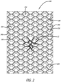
- a damaged acoustic honeycomb panel from the nacelle of a large jet engine is shown generally at 10d in FIG. 2 .
- the damaged acoustic honeycomb panel 10d has a damaged area or section shown at 12.
- the damaged acoustic honeycomb panel 10d can be made from any of the conventional materials used in making honeycomb panels including metals, ceramics, and composite materials.
- Exemplary metals include aluminum and aluminum alloys.
- Exemplary composites include aramid fibers, such as Nomex ® , carbon fibers, glass fibers and ceramic fibers and various combinations of these fibers with a suitable matrix resin.
- Exemplary matrix resins include thermosetting or thermoplastic resins where the thermosetting resin may or may not be toughend with a thermoplastic resin.
- the damaged acoustic honeycomb panel 10d has a first panel edge 14d and a second panel edge 16d.
- the damaged acoustic honeycomb panel 10d includes panel walls 18d that extend between the two panel edges 14d and 16d to define a plurality of panel honeycomb cells 20d.
- Each panel honeycomb cell 20d has a cross-sectional area that is measured perpendicular to the cell walls 18d.
- the depth or thickness of the damaged acoustic honeycomb panel 10d is the distance between the first panel edge 14d and the second panel edge 16d.
- the damaged acoustic honeycomb panel 10d includes acoustic septa 22d that are shown being located in all of the panel honeycomb cells 20d. Acoustic septa do not have to present in all panel honeycomb cells 20d and some cells may include more than one septa. Although any type of acoustic septum may be used, it is preferred that septa be the type of septum caps described in detail in U.S. PatentNos. 7,434,659; 7,510,052 and 7,854,298.
- septa are preferred because they are relatively flexible and retain their acoustic absorption properties when the acoustic honeycomb panel is in the form of a curved (nonplanar) structure, such as the acoustic honeycomb panel sections that present in jet engine nacelles.
- any of the acoustic materials typically used in acoustic honeycomb panels may be used to form the septa 22d.
- Acoustic materials are typically provided as relatively thin sheets that are perforated, porous or an open mesh fabric that is designed to provide noise attenuation. Perforated and porous sheets of various materials (metals, ceramics and plastics) may be used.
- the acoustic material is an open mesh fabric that is woven from monofilament fibers. The fibers may be composed of glass, carbon, ceramic or polymers.
- Monofilament polymer fibers made from polyamide, polyester, polyethylene chlorotrifluoroethylene (ECTFE), ethylene tetrafluoroethylene (ETFE), polytetrafluoroethylene (PTFE), polyphenylene sulfide (PPS), polyfluoroethylene propylene (FEP), polyether ether ketone (PEEK), polyamide 6 (Nylon, 6 PA6) and polyamide 12 (Nylon 12, PA12) are just a few examples.
- Open mesh fabric made from PEEK is preferred for high temperature applications. Open mesh acoustic fabrics are available from a wide variety of commercial sources. For example, sheets of open mesh acoustic fabric may be obtained from SEFAR America Inc. (Buffalo Division Headquarters 111 Calumet Street Depew, NY 14043) under the trade names SEFAR PETEX, SEFAR NITEX and SEFAR PEEKTEX.
- Solid sheets of acoustic material can also be used to form the septa 22d.
- perforations are formed in the solid sheet material either before or after the septa are placed within the honeycomb cell.
- the acoustic material be PEEK or a similar chemically resistant polymer material that is suitable for high temperature applications. Sheets or films of PEEK are available commercially from a number of sources, such as Victrex USA (Greenville, South Carolina) which produces sheets of PEEK under the tradename VICTREX ® PEEK TM polymer. Additional details regarding septum caps and their use in acoustic honeycombs are provided in published U.S. Patent Application No. 2012-0037449-A1 .
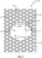
- the damaged area 12 of the acoustic honeycomb panel 10d is removed to form the acoustic honeycomb panel shown at 10a in FIG. 3 .
- the acoustic honeycomb panel 10a is the same as the damaged acoustic honeycomb panel 10d, except that the damaged area 12 has been removed to form a hole 13. Accordingly, the numbers identifying the elements of the acoustic honeycomb panel 10a as shown in FIG. 3 are the same as in FIG. 2 , except that "d" has been replaced with "a” to show that the two panels are the same, except for the removal of the damaged area 12 and formation of hole 13.
- the damaged honeycomb area 12 is removed by any of the known procedures for removing damaged honeycomb from an acoustic honeycomb panel.
- the removal method will depend upon the particular honeycomb material. Removal is typically accomplished by mechanical means, such as cutting or machining operations. However, thermal removal methods, such as laser cutting, may be used. Chemical removal methods are also possible depending upon the type of honeycomb material.
- the hole 13 extends between the first edge 14a. and second edge 16a of the acoustic honeycomb panel 10a.
- the hole 13 has a boundary 24a that is formed by the walls 26a of the portion of the acoustic honeycomb panel 10a that surrounds the hole 1 3.
- the hole 13 is shown as a circular cylinder that is formed by a circular boundary 24a. Holes with circular boundaries are preferred.
- the hole boundary 24a may be other shapes depending upon the damaged area being removed and the shape of the acoustic honeycomb panel in the damaged area.
- the hole boundary 24a may be square shaped, rectangular or other polygonal shape.
- the shape of the hole boundary 24a may also be irregular depending upon the size and shape of the damaged area.
- the hole boundary 24a is formed by end portions of the boundary walls 26a as shown at 28a.
- the hole boundary 24a is also formed by side portions of the boundary walls 26a as shown at 30a.
- a complex combination of boundary wall side portions 30a and end portions 28a form the hole boundary 24a.
- This complex combination of side portions and end portions will vary depending upon the size, shape and location of the hole 13 within the acoustic honeycomb panel 10a, as well as the particular acoustic honeycomb panel that is being repaired. It is preferred that the hole boundary be smooth and uniform in order to allow unhindered insertion of the acoustic honeycomb plug. Accordingly, any burrs or irregularities in the end or side portions of the boundary walls, which may occur during removal of the damaged area, should be removed, if possible.
- the acoustic honeycomb plug 32 has a first plug edge 34 and a second plug edge 36.
- the acoustic honeycomb plug 32 includes a plurality of plug walls 38 that extend between the first and second plug edges.
- the walls 38 define a plurality of plug honeycomb cells 40 which each has a cross-sectional area measured perpendicular to the plug walls 38.
- the plug depth or thickness is the distance between the first plug edge 34 and the second plug edge 36.
- the acoustic honeycomb plug 32 includes septa 42 that are shown being located in all of the plug honeycomb cells 40, Acoustic septa do not have to present in all plug honeycomb cells 40 and some cells may include more than one septa.
- any type of acoustic septum may be used in the same manner as the acoustic septa present in the acoustic honeycomb panel 10a. It is preferred, especially when repairing a damaged area, that the acoustic septa type and configuration in the acoustic honeycomb plug match the acoustic septa type and configuration of the acoustic honeycomb panel so that the acoustic properties of the original non-damaged acoustic honeycomb panel remain unchanged.
- the acoustic septa type and configuration may be varied widely when the acoustic honeycomb plug is being used to intentionally alter the acoustic properties of a non-damaged acoustic honeycomb panel.
- the acoustic honeycomb plug 32 has a plug perimeter 44 that is formed by those portions 46 of the plug walls that are located along the plug perimeter 44.
- the portions 46 of the plug wall that form the plug perimeter 44 may include a complex combination of end portions 48 and side portions 50. This complex combination of side portions and end portions that make up the plug perimeter will also vary depending upon the size, shape and location of the hole 13 that is being plugged 10a, as well as the particular acoustic honeycomb that is being used for the plug material. It is preferred that the plug perimeter be smooth and uniform in order to allow unhindered insertion of the acoustic honeycomb plug into hole 13. Accordingly, any burrs or irregularities in the end or side portions that form the plug perimeter, which may occur during formation of the plug, should be removed, if possible.
- the acoustic honeycomb plug 32 is formed in the same manner as the damaged area is removed from the existing acoustic honeycomb panel 10d.
- a plug that matches the size and shape of the hole 13 is mechanically, thermally or chemically removed from an undamaged acoustic honeycomb panel that has acoustic, physical and dimensional properties which match the damaged panel 10d.
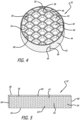
- the acoustic honeycomb plug 32 is shown as a seam coated acoustic honeycomb plug in which a honeycomb seam 52 has been attached to the plug 32 along the plug perimeter 44.
- the honeycomb seam 52 is shown in FIG. 5 prior to the honeycomb seam being wrapped around the plug perimeter 44.
- the honeycomb seam 52 includes a honeycomb support 54 that is in the shape of a ribbon having a thickness which is the distance between a first support edge 56 and a second support edge 58.
- the honeycomb support 54 has a width which is the distance between a first support side 60 and a second support side 62.
- the honeycomb support 54 includes a plurality of support walls 63 that extend between the first support edge 56 and second support edge 58.
- the support walls 63 form a plurality of support honeycomb cells 65 which each has a cross-sectional area measured perpendicular to the support walls 63.
- the support honeycomb cells are filled with an adhesive 67 that is present in a sufficient amount to provide bonding of the acoustic honeycomb plug 32 to the hole boundary 24a of acoustic honeycomb panel 10a.
- the honeycomb seam 52 has a head end 64 and a tail end 66 with the length of the honeycomb seam being the distance between the head end 64 and tail end 66.
- the length of the honeycomb seam matches the circumference of the plug perimeter so that the head end 64 and tail end 66 are located next to or adjacent each other when the honeycomb seam is applied to the plug perimeter as shown in FIG. 4 to form a cylindrical seam.
- Multiple segments of honeycomb seam may be used to form a single seam, if desired. Multiple honeycomb seam segments may be required when the size of the hole being repaired is relatively large. In general, however, it is preferred that the honeycomb seam be formed from a single segment or piece of honeycomb support.
- the material used to make the honeycomb support 54 can be any of the same materials that are used to make the acoustic honeycomb panels.
- the material should be sufficiently thin so that it can be flexed to provide enough flexibility" for wrapping around tire plug perimeter to form a cylindrical seam.
- the honeycomb support material be the same as that used in making the acoustic honeycomb panel and acoustic honeycomb plug.
- the thickness of the material used to form the honeycomb support can be varied with it being preferred that the material be as thin as possible while still providing necessary support to the adhesive.
- the adhesive 67 can be any suitable adhesive that is typically used in connection with the fabrication of honeycomb panels.
- the same adhesives that are used to bond the septa within the honeycomb cells are generally also suitable for use as the seam adhesive.
- Preferred adhesives include those that are stable at high temperature (300 - 400°F).
- Exemplary adhesives include epoxies, acrylics, phenolics, cyanoacrylates, bismaleimides, polyamide-imides, and polyimides. Polyamide-imide adhesives are particularly preferred.
- the honeycomb support 54 structure is preferably loaded with the desired adhesive so that the adhesive fills substantially all of the cells in the honeycomb support structure and coats the edges of the honeycomb support structure, The adhesive may extend somewhat past the edges of the honeycomb support 54, if desired.
- FIG. 6 shows the acoustic honeycomb plug 32b after it has been inserted into hole 13b of panel 16b.
- the honeycomb seam 52b is shown in place within the seam channel 70 that is located between the hole boundary 24b and plug perimeter 44b.
- the numbers identifying the elements of the acoustic honeycomb panel 10b, as shown in FIG. 6 are the same as in FIGS. 3 and 4 , except that "b" has been added. This shows that the acoustic honeycomb panels and seam coated acoustic honeycomb plugs remain the same after they are combined to form the plugged acoustic honeycomb panel 10b.
- the respective sizes of the plug perimeter 44b and hole boundary 24b are chosen so that a seam channel 70 is formed between the panel and plug.
- the seam channel 70 has a width which is the distance between the plug perimeter 44b and the hole boundary 24b.
- the depth of the seam channel 70 is equal to the plug depth at the plug perimeter 44b and the panel depth at the hole boundary 24b. It is preferred that the plug depth and panel depths are the same.
- the seam channel 70 also has a circumference that is determined by the plug perimeter circumference 44b and hole boundary 24b.
- the seam channel width and honeycomb seam thickness are chosen so that the acoustic honeycomb plug 32b can be inserted into acoustic honeycomb panel 10b, as shown in FIG. 6 . It is preferred that the width of the seam channel is slightly larger than the thickness of the honeycomb seam. The difference between the seam channel width and the honeycomb seam thickness should be as small as possible to provide adequate bonding of the adhesive. At the same time, this difference must also be large enough to allow the acoustic honeycomb plug to be inserted into position within the acoustic honeycomb panel without undue interference of premature seizing between the acoustic honeycomb plug, acoustic honeycomb panel and/or the honeycomb seam.
- a repaired acoustic honeycomb panel is shown at 10c in FIG. 1 .
- the repaired acoustic honeycomb panel 10c includes the acoustic honeycomb plug 32c which is securely and permanently bonded within the repaired acoustic honeycomb panel 10c by way of the cured honeycomb seam 52c.
- the numbers identifying the elements of the repaired acoustic honeycomb panel 10c are the same as in FIGS. 3 , 4 and 6 , except that "c" has been added.
- the honeycomb seam 52 is preferably located either on the plug perimeter 44 or hole boundary 24a prior to insertion of the acoustic honeycomb plug 32 into the acoustic honeycomb panel 10a.
- Many of the suitable adhesives are inherently tacky or sticky at room temperature (20°C to 25°C) or when heated to a particular softening temperature. It is preferred that the honeycomb seam be applied to the plug perimeter or hole boundary and pressed in place while the adhesive is tacky. The inherent tack of the adhesive holds the honeycomb seam in place during insertion of the acoustic honeycomb plug into the acoustic honeycomb panel.
- the adhesive be cooled or otherwise treated so that it is not tacky when the acoustic honeycomb plug is inserted into the hole. Keeping the adhesive in a non-tacky state eliminates the problems associated with premature adhesion of the acoustic honeycomb plug during insertion into the acoustic honeycomb panel.
- the adhesive is allowed to return to its tacky state to provide temporary adherence of the acoustic honeycomb plug perimeter to the hole boundary of the acoustic honeycomb panel, as shown in FIG. 6 .
- the adhesive is then heated or otherwise treated to cure or set the adhesive to form the final repaired panel, as shown in FIG. 1 .
- honeycomb seam adhesives are preferred as the honeycomb seam adhesive. These adhesives are inherently tacky at room temperature.
- a honeycomb seam containing a polyamide-imide adhesive is applied to the perimeter of an acoustic honeycomb plug at room temperature and adhered in place using slight pressure to form a seam coated acoustic honeycomb plug.
- the seam coated acoustic honeycomb plug is then cooled to a temperature of 0°C or less so that the adhesive is no longer tacky. Cooling to a temperature of 0°C is preferred.
- the seam coated adhesive plug is maintained at the cooled temperature during insertion into the acoustic honeycomb panel.
- the seam coated adhesive plug is then allowed to return to room temperature so that the adhesive regains its inherent tackiness to provide temporary adherence of the seam coated adhesive plug to the acoustic honeycomb panel.
- the adhesive is then heated to a temperature of 177°C for 60 minutes in order to cure the polyamide-imide adhesive and permanently bond the acoustic honeycomb plug within the acoustic honeycomb panel.
- the depth of the cells ranges from 0.25 to 3 inches or more.
- Exemplary acoustic honeycomb panels for repair that are used in the jet engines of large aircraft will typically have hexagonal cells that have a cross-sectional area of around 0.1 to 0.5 square inch, wall thicknesses of around 0.025 to 0.05 inch and a depth of around 1.0 to 2.0 inches.
- the seam channel dimension will vary depending upon the dimensions and shape of the acoustic honeycomb panel being repaired or altered, the size and shape of the acoustic honeycomb plug and the size and shape of the honeycomb seam.
- the seam channels will have a channel width of from 0.35 to 0.50 inch.
- Preferred seam channel thicknesses for use in repairing acoustic honeycomb panels found in the jet engines of large aircraft are from 0.060 to 0.100 inch.
- the depth of the seam channel will typically range from 0.25 inch to 3 inches or more.
- Preferred seam channel depths for use in repairing acoustic honeycomb panels found in the jet engines of large aircraft are from 1 to 2 inches.
- the circumference of the seam channel will depend upon the size of the hole being plugged and the size of the acoustic honeycomb plug. Typical seam channel circumferences will range from a minimum of 10 inches to much larger circumferences depending upon the size of the damaged area. It was found that 10 inches is the minimum circumference of the seam channel that is required when repairing acoustic honeycomb panels found in the jet engines of large aircraft.
- the honeycomb seam should have an overall thickness, which includes the honeycomb support and adhesive, which is from 0.025 to 0.050 inch less than the width of the seam channel.
- the adhesive will preferably extend slightly past the first and second support edges of the honeycomb support.
- the preferred thickness of the adhesive extending out past the first and second support edges is on the order of 0.005 to 0.010 inch.
- the thickness of the honeycomb seam is preferably from 0.025 to 0.050 inch less than the seam channel width when repairing damaged areas of acoustic honeycomb panels found in the jet engines of large aircraft that require a seam channel having dimensions that fall within the ranges set forth above.
Landscapes
- Engineering & Computer Science (AREA)
- Aviation & Aerospace Engineering (AREA)
- Physics & Mathematics (AREA)
- Acoustics & Sound (AREA)
- Multimedia (AREA)
- Mechanical Engineering (AREA)
- Manufacturing & Machinery (AREA)
- Transportation (AREA)
- Chemical & Material Sciences (AREA)
- Combustion & Propulsion (AREA)
- Soundproofing, Sound Blocking, And Sound Damping (AREA)
- Polyurethanes Or Polyureas (AREA)
Description
- The present invention relates generally to forming a plug of acoustic honeycomb in an existing acoustic honeycomb panel. The acoustic honeycomb plug is most often used to repair a damaged area of an existing panel. However, the acoustic honeycomb plug may also be used to replace a non-damaged area of the panel in order to provide desired alterations in the acoustic properties of the panel. The invention is particularly directed to methods which involve removing the damaged section of the acoustic honeycomb and inserting a replacement acoustic honeycomb section or plug in a way which limits alternations in the acoustic properties of the repaired acoustic honeycomb. The invention is useful for repairing acoustic honeycomb panels that are used in the acoustic damping structures of jet engines.
- It is widely recognized that the best way of dealing with excess noise generated by a specific source is to treat the noise at the source. This is typically accomplished by adding acoustic treatments to the structure at the noise source. One particularly problematic noise source is the jet engine used to propel aircraft. Acoustic treatments are typically incorporated in the engine inlet, nacelle and exhaust structures. These acoustic treatments include acoustic resonators that contain relatively thin acoustic materials or grids that have millions of holes that create acoustic impedance to the sound energy generated by the engine. The basic problem that faces engineers is how to add these thin and flexible acoustic materials into the structural elements of the jet engine and surrounding nacelle to provide desired noise attenuation.
- Honeycomb has been a popular material for use in aircraft and aerospace vehicles because it is relatively strong and lightweight and each honeycomb cell can be used as an acoustic resonator. For acoustic applications, the goal has been to somehow incorporate the thin acoustic materials into the honeycomb structure so that the honeycomb cells are closed or covered. The closing of the cells with acoustic material creates the acoustic impedance upon which the resonator is based.
- Forming acoustic style honeycomb into complex curved structures required for engine nacelles is a major design consideration. It is very difficult to form a single honeycomb into an engine nacelle without significantly altering the honeycomb and its acoustic properties. Accordingly, numerous sections of curved or slightly curved acoustic honeycomb sections are typically spliced together to form the cylindrical nacelle structure.
- The sides of the honeycomb that are spliced together are composed of numerous protruding cell walls that are typically referred to as "dog ears". The protruding cell walls that make up the dog ears have ends that present a relatively small surface area for bonding of the two honeycomb sections together. In addition, it is very difficult to position the honeycomb sections so that the ends of the dog ears on opposing honeycomb sections are lined up and close enough for bonding.
- The preceding bonding/splicing issues have been typically solved by filling the seam line, and the partial cells that border the seam line, with an adhesive. The adhesive is used to completely fill all of the open spaces along the seam line to provide a solid and secure bond. For aerospace applications, the adhesive is typically a foam-type adhesive to keep the weight of the seam at a minimum. An advantage of filling the seam line and surrounding partial cells with adhesive is that the surface area of the honeycomb which is available for bonding is much larger than the surface area provided by the ends of the dog ears. A strong bond is achieved due to the relatively large surface area of honeycomb that interacts with the adhesive to form the seam. In addition, a foam-type adhesive can be used to bond together honeycomb sides that are curved and/or serpentine. Since bonding is accomplished by simply filling the seam line with adhesive, the shape and orientation of the dog ears and partial cells along the seam line can vary without affecting the overall performance of the seam.
- The use of an adhesive seam line does have disadvantages. For example, the acoustic properties of the honeycomb cells that are filled with adhesive are significantly altered or destroyed. Solid adhesive seams tend to be wide and relatively heavy, which is not desirable for aerospace applications where limiting weight is an important design consideration. Also, the strength of the seam can vary depending upon the orientation of the dog ears on opposite sides of the seam line. In addition, the relatively wide adhesive seams tend to be stiff and may limit the ability to bend or otherwise shape the overall bonded honeycombs into a curved structure, such as an engine nacelle.
- One successful way of seaming acoustic honeycomb sections together involves using an adhesive that is supported by a ribbon-shaped honeycomb support. It was discovered that narrow and strong seams could be provided between honeycomb sections when a ribbon-shaped honeycomb support was used in combination with the adhesive. The use of honeycomb-supported adhesive seams to bond acoustic honeycomb sections together is described in
U.S. Patent No. 8,579,076 B2 . The honeycomb supported seams are much thinner than prior foam-type adhesive seams and can be used regardless of whether or not the protruding ends of the honeycomb are aligned along the seam. The thinner seams provided by the honeycomb-supported adhesive also minimize any interference with the acoustic properties of the spliced honeycomb. The honeycomb-supported adhesive seams are flexible so that they can be used to bond together curved honeycomb sections. - Acoustic honeycomb panels are sometimes damaged during manufacture or use. In order to repair the damaged section, it is necessary to remove the damaged portion of acoustic honeycomb and replace it with a plug of matching acoustic honeycomb that is bonded in place. Many of the same issues involved in seaming honeycomb sections together, as discussed above, are also presented when locating and bonding a plug of acoustic honeycomb in the hole formed when the damaged honeycomb has been removed. A number of other complex issues are also presented due to the fact that the acoustic honeycomb plug has to be inserted into the damaged panel rather than being bonded to an exposed edge of the acoustic honeycomb. In addition, the insertion and bonding of the acoustic honeycomb plug must be accomplished while keeping in mind that the acoustic properties of the repaired acoustic honeycomb panel should match the acoustic properties of the original non-damaged acoustic honeycomb panel.
-
US 8,696,843 discloses a method of repairing an acoustically treated area of a composite honeycomb sandwich structure in which an impaired section of the honeycomb core is removed and replaced with a honeycomb repair plug and the cell walls of the repair plug are bonded to cell walls of the core. - In accordance with the present invention, it was discovered that a honeycomb supported adhesive seam may be used to bond an acoustic honeycomb plug into a hole located in an existing acoustic honeycomb. The honeycomb supported adhesive seam was found to be effective in filling the seam channel that is formed between the acoustic honeycomb plug and the acoustic honeycomb panel to provide a secure bond without adversely altering the acoustic properties of the plugged acoustic honeycomb panel.
- The present invention provides a method for plugging an acoustic honeycomb panel according to claim 1.
- The invention also relates to a plugged acoustic honeycomb panel according to claim 7.
- Further details of the invention are set forth in the dependent claims.
- The above described and many other features and attendant advantages of the present invention will become better understood by reference to the following detailed description when taken in conjunction with the accompanying drawings.
-
-
FIG. 1 shows a repaired acoustic honeycomb panel in which an acoustic honeycomb plug has been inserted into the panel and bonded in place using a honeycomb seam in accordance with the present invention. -
FIG. 2 shows a damaged acoustic honeycomb panel prior to the damaged area being removed. -
FIG. 3 shows the damaged acoustic honeycomb panel after the damaged area has been removed. -
FIG. 4 shows a seam coated acoustic honeycomb plug in which the honeycomb seam has been adhered to the perimeter of the acoustic honeycomb plug. -
FIG. 5 shows an exemplary honeycomb seam prior to it being applied either to the perimeter of the acoustic honeycomb plug or to the boundary of the hole in the damaged acoustic honeycomb panel. -
FIG. 6 shows the seam coated acoustic honeycomb plug located the acoustic honeycomb panel prior to curing of the adhesive to form the repaired acoustic honeycomb panel shown inFIG. 1 . - The present invention may be used to form acoustic honeycomb plugs in a wide variety of complex acoustic honeycomb panel types and shapes. The following detailed description is directed to repairing the damaged area in an acoustic honeycomb panel of the type found in the nacelles and other sound damping structures present in large aircraft jet engines. This is a preferred use for the invention. However, it will be understood that the invention is also applicable to plugging holes in acoustic honeycomb panels with an acoustic honeycomb plug regardless of the reason for which the hole was made.
- A damaged acoustic honeycomb panel from the nacelle of a large jet engine is shown generally at 10d in
FIG. 2 . The damagedacoustic honeycomb panel 10d has a damaged area or section shown at 12. The damagedacoustic honeycomb panel 10d can be made from any of the conventional materials used in making honeycomb panels including metals, ceramics, and composite materials. Exemplary metals include aluminum and aluminum alloys. Exemplary composites include aramid fibers, such as Nomex®, carbon fibers, glass fibers and ceramic fibers and various combinations of these fibers with a suitable matrix resin. Exemplary matrix resins include thermosetting or thermoplastic resins where the thermosetting resin may or may not be toughend with a thermoplastic resin. - The damaged
acoustic honeycomb panel 10d has afirst panel edge 14d and asecond panel edge 16d. The damagedacoustic honeycomb panel 10d includespanel walls 18d that extend between the twopanel edges panel honeycomb cells 20d. Eachpanel honeycomb cell 20d has a cross-sectional area that is measured perpendicular to thecell walls 18d. The depth or thickness of the damagedacoustic honeycomb panel 10d is the distance between thefirst panel edge 14d and thesecond panel edge 16d. - The damaged
acoustic honeycomb panel 10d includesacoustic septa 22d that are shown being located in all of thepanel honeycomb cells 20d. Acoustic septa do not have to present in allpanel honeycomb cells 20d and some cells may include more than one septa. Although any type of acoustic septum may be used, it is preferred that septa be the type of septum caps described in detail in U.S. PatentNos. 7,434,659; 7,510,052 and 7,854,298. These types of septa are preferred because they are relatively flexible and retain their acoustic absorption properties when the acoustic honeycomb panel is in the form of a curved (nonplanar) structure, such as the acoustic honeycomb panel sections that present in jet engine nacelles. - Any of the acoustic materials typically used in acoustic honeycomb panels may be used to form the
septa 22d. Acoustic materials are typically provided as relatively thin sheets that are perforated, porous or an open mesh fabric that is designed to provide noise attenuation. Perforated and porous sheets of various materials (metals, ceramics and plastics) may be used. In one preferred embodiment the acoustic material is an open mesh fabric that is woven from monofilament fibers. The fibers may be composed of glass, carbon, ceramic or polymers. Monofilament polymer fibers made from polyamide, polyester, polyethylene chlorotrifluoroethylene (ECTFE), ethylene tetrafluoroethylene (ETFE), polytetrafluoroethylene (PTFE), polyphenylene sulfide (PPS), polyfluoroethylene propylene (FEP), polyether ether ketone (PEEK), polyamide 6 (Nylon, 6 PA6) and polyamide 12 (Nylon 12, PA12) are just a few examples. Open mesh fabric made from PEEK is preferred for high temperature applications. Open mesh acoustic fabrics are available from a wide variety of commercial sources. For example, sheets of open mesh acoustic fabric may be obtained from SEFAR America Inc. (Buffalo Division Headquarters 111 Calumet Street Depew, NY 14043) under the trade names SEFAR PETEX, SEFAR NITEX and SEFAR PEEKTEX. - Solid sheets of acoustic material can also be used to form the
septa 22d. In this case, perforations are formed in the solid sheet material either before or after the septa are placed within the honeycomb cell. Although metals, ceramics and plastics of the type identified above may be used to make perforated septa, it is preferred that the acoustic material be PEEK or a similar chemically resistant polymer material that is suitable for high temperature applications. Sheets or films of PEEK are available commercially from a number of sources, such as Victrex USA (Greenville, South Carolina) which produces sheets of PEEK under the tradename VICTREX® PEEK™ polymer. Additional details regarding septum caps and their use in acoustic honeycombs are provided in publishedU.S. Patent Application No. 2012-0037449-A1 . - The damaged
area 12 of theacoustic honeycomb panel 10d is removed to form the acoustic honeycomb panel shown at 10a inFIG. 3 . Theacoustic honeycomb panel 10a is the same as the damagedacoustic honeycomb panel 10d, except that the damagedarea 12 has been removed to form ahole 13. Accordingly, the numbers identifying the elements of theacoustic honeycomb panel 10a as shown inFIG. 3 are the same as inFIG. 2 , except that "d" has been replaced with "a" to show that the two panels are the same, except for the removal of the damagedarea 12 and formation ofhole 13. - The damaged
honeycomb area 12 is removed by any of the known procedures for removing damaged honeycomb from an acoustic honeycomb panel. The removal method will depend upon the particular honeycomb material. Removal is typically accomplished by mechanical means, such as cutting or machining operations. However, thermal removal methods, such as laser cutting, may be used. Chemical removal methods are also possible depending upon the type of honeycomb material. - The
hole 13 extends between the first edge 14a. andsecond edge 16a of theacoustic honeycomb panel 10a. Thehole 13 has aboundary 24a that is formed by thewalls 26a of the portion of theacoustic honeycomb panel 10a that surrounds the hole 1 3. Thehole 13 is shown as a circular cylinder that is formed by acircular boundary 24a. Holes with circular boundaries are preferred. However, thehole boundary 24a may be other shapes depending upon the damaged area being removed and the shape of the acoustic honeycomb panel in the damaged area. For example, thehole boundary 24a may be square shaped, rectangular or other polygonal shape. The shape of thehole boundary 24a may also be irregular depending upon the size and shape of the damaged area. - The
hole boundary 24a is formed by end portions of theboundary walls 26a as shown at 28a. Thehole boundary 24a is also formed by side portions of theboundary walls 26a as shown at 30a. As can be seen fromFIG. 3 , a complex combination of boundarywall side portions 30a andend portions 28a form thehole boundary 24a. This complex combination of side portions and end portions will vary depending upon the size, shape and location of thehole 13 within theacoustic honeycomb panel 10a, as well as the particular acoustic honeycomb panel that is being repaired. It is preferred that the hole boundary be smooth and uniform in order to allow unhindered insertion of the acoustic honeycomb plug. Accordingly, any burrs or irregularities in the end or side portions of the boundary walls, which may occur during removal of the damaged area, should be removed, if possible. - An exemplary acoustic honeycomb plug is shown at 32 in
FIG. 4 . Theacoustic honeycomb plug 32 has afirst plug edge 34 and asecond plug edge 36. Theacoustic honeycomb plug 32 includes a plurality ofplug walls 38 that extend between the first and second plug edges. Thewalls 38 define a plurality ofplug honeycomb cells 40 which each has a cross-sectional area measured perpendicular to theplug walls 38. The plug depth or thickness is the distance between thefirst plug edge 34 and thesecond plug edge 36. - The
acoustic honeycomb plug 32 includessepta 42 that are shown being located in all of theplug honeycomb cells 40, Acoustic septa do not have to present in all plughoneycomb cells 40 and some cells may include more than one septa. Although any type of acoustic septum may be used in the same manner as the acoustic septa present in theacoustic honeycomb panel 10a. It is preferred, especially when repairing a damaged area, that the acoustic septa type and configuration in the acoustic honeycomb plug match the acoustic septa type and configuration of the acoustic honeycomb panel so that the acoustic properties of the original non-damaged acoustic honeycomb panel remain unchanged. However, the acoustic septa type and configuration may be varied widely when the acoustic honeycomb plug is being used to intentionally alter the acoustic properties of a non-damaged acoustic honeycomb panel. - The
acoustic honeycomb plug 32 has aplug perimeter 44 that is formed by thoseportions 46 of the plug walls that are located along theplug perimeter 44. In a manner similar to thepanel boundary 24a, theportions 46 of the plug wall that form theplug perimeter 44 may include a complex combination ofend portions 48 andside portions 50. This complex combination of side portions and end portions that make up the plug perimeter will also vary depending upon the size, shape and location of thehole 13 that is being plugged 10a, as well as the particular acoustic honeycomb that is being used for the plug material. It is preferred that the plug perimeter be smooth and uniform in order to allow unhindered insertion of the acoustic honeycomb plug intohole 13. Accordingly, any burrs or irregularities in the end or side portions that form the plug perimeter, which may occur during formation of the plug, should be removed, if possible. - The
acoustic honeycomb plug 32 is formed in the same manner as the damaged area is removed from the existingacoustic honeycomb panel 10d. When repairing a damaged panel to restore original acoustic properties, a plug that matches the size and shape of thehole 13 is mechanically, thermally or chemically removed from an undamaged acoustic honeycomb panel that has acoustic, physical and dimensional properties which match the damagedpanel 10d. - The
acoustic honeycomb plug 32 is shown as a seam coated acoustic honeycomb plug in which ahoneycomb seam 52 has been attached to theplug 32 along theplug perimeter 44. Thehoneycomb seam 52 is shown inFIG. 5 prior to the honeycomb seam being wrapped around theplug perimeter 44. - The
honeycomb seam 52 includes ahoneycomb support 54 that is in the shape of a ribbon having a thickness which is the distance between afirst support edge 56 and asecond support edge 58. Thehoneycomb support 54 has a width which is the distance between afirst support side 60 and asecond support side 62. Thehoneycomb support 54 includes a plurality ofsupport walls 63 that extend between thefirst support edge 56 andsecond support edge 58. Thesupport walls 63 form a plurality ofsupport honeycomb cells 65 which each has a cross-sectional area measured perpendicular to thesupport walls 63. The support honeycomb cells are filled with an adhesive 67 that is present in a sufficient amount to provide bonding of theacoustic honeycomb plug 32 to thehole boundary 24a ofacoustic honeycomb panel 10a. - The
honeycomb seam 52 has ahead end 64 and atail end 66 with the length of the honeycomb seam being the distance between thehead end 64 andtail end 66. The length of the honeycomb seam matches the circumference of the plug perimeter so that thehead end 64 andtail end 66 are located next to or adjacent each other when the honeycomb seam is applied to the plug perimeter as shown inFIG. 4 to form a cylindrical seam. Multiple segments of honeycomb seam may be used to form a single seam, if desired. Multiple honeycomb seam segments may be required when the size of the hole being repaired is relatively large. In general, however, it is preferred that the honeycomb seam be formed from a single segment or piece of honeycomb support. - The material used to make the
honeycomb support 54 can be any of the same materials that are used to make the acoustic honeycomb panels. The material should be sufficiently thin so that it can be flexed to provide enough flexibility" for wrapping around tire plug perimeter to form a cylindrical seam. It is preferred that the honeycomb support material be the same as that used in making the acoustic honeycomb panel and acoustic honeycomb plug. The thickness of the material used to form the honeycomb support can be varied with it being preferred that the material be as thin as possible while still providing necessary support to the adhesive. - The adhesive 67 can be any suitable adhesive that is typically used in connection with the fabrication of honeycomb panels. The same adhesives that are used to bond the septa within the honeycomb cells are generally also suitable for use as the seam adhesive. Preferred adhesives include those that are stable at high temperature (300 - 400°F). Exemplary adhesives include epoxies, acrylics, phenolics, cyanoacrylates, bismaleimides, polyamide-imides, and polyimides. Polyamide-imide adhesives are particularly preferred. The
honeycomb support 54 structure is preferably loaded with the desired adhesive so that the adhesive fills substantially all of the cells in the honeycomb support structure and coats the edges of the honeycomb support structure, The adhesive may extend somewhat past the edges of thehoneycomb support 54, if desired. -
FIG. 6 shows theacoustic honeycomb plug 32b after it has been inserted intohole 13b of panel 16b. Thehoneycomb seam 52b is shown in place within theseam channel 70 that is located between thehole boundary 24b and plugperimeter 44b. The numbers identifying the elements of theacoustic honeycomb panel 10b, as shown inFIG. 6 , are the same as inFIGS. 3 and4 , except that "b" has been added. This shows that the acoustic honeycomb panels and seam coated acoustic honeycomb plugs remain the same after they are combined to form the pluggedacoustic honeycomb panel 10b. - The respective sizes of the
plug perimeter 44b andhole boundary 24b are chosen so that aseam channel 70 is formed between the panel and plug. Theseam channel 70 has a width which is the distance between theplug perimeter 44b and thehole boundary 24b. The depth of theseam channel 70 is equal to the plug depth at theplug perimeter 44b and the panel depth at thehole boundary 24b. It is preferred that the plug depth and panel depths are the same. Theseam channel 70 also has a circumference that is determined by theplug perimeter circumference 44b andhole boundary 24b. - The seam channel width and honeycomb seam thickness are chosen so that the
acoustic honeycomb plug 32b can be inserted intoacoustic honeycomb panel 10b, as shown inFIG. 6 . It is preferred that the width of the seam channel is slightly larger than the thickness of the honeycomb seam. The difference between the seam channel width and the honeycomb seam thickness should be as small as possible to provide adequate bonding of the adhesive. At the same time, this difference must also be large enough to allow the acoustic honeycomb plug to be inserted into position within the acoustic honeycomb panel without undue interference of premature seizing between the acoustic honeycomb plug, acoustic honeycomb panel and/or the honeycomb seam. - Once the acoustic honeycomb plug has been inserted into position, the adhesive is cured or otherwise allowed to set up in order to provide a repaired acoustic honeycomb panel. A repaired acoustic honeycomb panel is shown at 10c in
FIG. 1 . The repairedacoustic honeycomb panel 10c includes theacoustic honeycomb plug 32c which is securely and permanently bonded within the repairedacoustic honeycomb panel 10c by way of the curedhoneycomb seam 52c. The numbers identifying the elements of the repairedacoustic honeycomb panel 10c are the same as inFIGS. 3 ,4 and6 , except that "c" has been added. This shows that the acoustic honeycomb panels and seam coated acoustic honeycomb plugs remain the same after they are combined to form the repairedacoustic honeycomb panel 10c, except for thehoneycomb seam 52c being cured or otherwise set to form a permanent bond between theacoustic honeycomb panel 10c andacoustic honeycomb plug 32c. - The
honeycomb seam 52 is preferably located either on theplug perimeter 44 orhole boundary 24a prior to insertion of theacoustic honeycomb plug 32 into theacoustic honeycomb panel 10a. Many of the suitable adhesives are inherently tacky or sticky at room temperature (20°C to 25°C) or when heated to a particular softening temperature. It is preferred that the honeycomb seam be applied to the plug perimeter or hole boundary and pressed in place while the adhesive is tacky. The inherent tack of the adhesive holds the honeycomb seam in place during insertion of the acoustic honeycomb plug into the acoustic honeycomb panel. - The complexities of the shapes of the honeycomb walls along the plug perimeter and the hole boundary, as well as the respective sizes of the seam channel width and honeycomb seam thickness being close to each other, make it difficult to insert the acoustic honeycomb plug into the acoustic honeycomb panel without there being some contact of tire adhesive with either the plug perimeter, when the seam is located in the acoustic honeycomb panel, or the hole boundary, when the seam is located on the plug perimeter. Such adhesive contact is preferably avoided since it can cause premature adhesion and seizing of the acoustic honeycomb plug within the hole before the plug reaches the desired position within the acoustic honeycomb panel.
- In order to eliminate the problem associated with a tacky adhesive causing premature adhesion of the acoustic honeycomb plug, it is preferred that the adhesive be cooled or otherwise treated so that it is not tacky when the acoustic honeycomb plug is inserted into the hole. Keeping the adhesive in a non-tacky state eliminates the problems associated with premature adhesion of the acoustic honeycomb plug during insertion into the acoustic honeycomb panel. Once in place within the acoustic honeycomb panel, the adhesive is allowed to return to its tacky state to provide temporary adherence of the acoustic honeycomb plug perimeter to the hole boundary of the acoustic honeycomb panel, as shown in
FIG. 6 . The adhesive is then heated or otherwise treated to cure or set the adhesive to form the final repaired panel, as shown inFIG. 1 . - Polyamide-imide adhesives are preferred as the honeycomb seam adhesive. These adhesives are inherently tacky at room temperature. In a preferred embodiment, a honeycomb seam containing a polyamide-imide adhesive is applied to the perimeter of an acoustic honeycomb plug at room temperature and adhered in place using slight pressure to form a seam coated acoustic honeycomb plug. The seam coated acoustic honeycomb plug is then cooled to a temperature of 0°C or less so that the adhesive is no longer tacky. Cooling to a temperature of 0°C is preferred. The seam coated adhesive plug is maintained at the cooled temperature during insertion into the acoustic honeycomb panel. The seam coated adhesive plug is then allowed to return to room temperature so that the adhesive regains its inherent tackiness to provide temporary adherence of the seam coated adhesive plug to the acoustic honeycomb panel. The adhesive is then heated to a temperature of 177°C for 60 minutes in order to cure the polyamide-imide adhesive and permanently bond the acoustic honeycomb plug within the acoustic honeycomb panel.
- The acoustic honeycomb panels that can be repaired using the acoustic honeycomb plugs of the present invention can vary widely in cell cross-sectional area, wall thickness and depth. Typical acoustic honeycomb panels will have cells with cross-sectional areas ranging from 0.05 square inch to 1 square inch or more (here and in the rest of the description, 1 square inch = 6,45 square centimeters).
- The wall thicknesses of the honeycomb material will typically range from 0.001 to 0.050 inch (here and in the rest of the description, 1 inch = 2,54 cm).
- The depth of the cells (core thickness) ranges from 0.25 to 3 inches or more. Exemplary acoustic honeycomb panels for repair that are used in the jet engines of large aircraft will typically have hexagonal cells that have a cross-sectional area of around 0.1 to 0.5 square inch, wall thicknesses of around 0.025 to 0.05 inch and a depth of around 1.0 to 2.0 inches.
- The seam channel dimension will vary depending upon the dimensions and shape of the acoustic honeycomb panel being repaired or altered, the size and shape of the acoustic honeycomb plug and the size and shape of the honeycomb seam. Typically, the seam channels will have a channel width of from 0.35 to 0.50 inch. Preferred seam channel thicknesses for use in repairing acoustic honeycomb panels found in the jet engines of large aircraft are from 0.060 to 0.100 inch. The depth of the seam channel will typically range from 0.25 inch to 3 inches or more. Preferred seam channel depths for use in repairing acoustic honeycomb panels found in the jet engines of large aircraft are from 1 to 2 inches. The circumference of the seam channel will depend upon the size of the hole being plugged and the size of the acoustic honeycomb plug. Typical seam channel circumferences will range from a minimum of 10 inches to much larger circumferences depending upon the size of the damaged area. It was found that 10 inches is the minimum circumference of the seam channel that is required when repairing acoustic honeycomb panels found in the jet engines of large aircraft.
- The honeycomb seam should have an overall thickness, which includes the honeycomb support and adhesive, which is from 0.025 to 0.050 inch less than the width of the seam channel. The adhesive will preferably extend slightly past the first and second support edges of the honeycomb support. The preferred thickness of the adhesive extending out past the first and second support edges is on the order of 0.005 to 0.010 inch. The thickness of the honeycomb seam is preferably from 0.025 to 0.050 inch less than the seam channel width when repairing damaged areas of acoustic honeycomb panels found in the jet engines of large aircraft that require a seam channel having dimensions that fall within the ranges set forth above.
- Having thus described exemplary embodiments of the present invention, it should be noted by those skilled in the art that the within disclosures are exemplary only and that various other alternatives, adaptations and modifications may be made within the scope of the present invention. Accordingly, the present invention is not limited by the above-described embodiments, but is only limited by the following claims.
Claims (14)
- A method for plugging an acoustic honeycomb panel (10), said method comprising the steps of:A) providing an acoustic honeycomb panel (10) comprising a first panel edge (14) and a second panel edge (16), said acoustic honeycomb panel (10) further comprising a plurality of panel walls (18) that extend between said first and second panel edges (14, 16), said panel walls (18) defining a plurality of panel honeycomb cells (20) wherein each of said panel honeycomb cells (20) has a cross-sectional area measured perpendicular to said panel walls (18) and a panel depth defined by the distance between the first and second panel edges (14, 16), said acoustic honeycomb panel (10) further comprising acoustic septa (22) located within said plurality of panel honeycomb cells (20), said acoustic honeycomb panel (10) comprising a hole (13) extending between the first and second panel edges (14,16), said hole (13) having a boundary ( 24) defined by the walls (26) of a portion of said panel honeycomb cells (20) that surround said hole (13);B) providing an acoustic honeycomb plug (32) comprising a first plug edge (34) and a second plug edge (36), said acoustic honeycomb plug (32) further comprising a plurality of plug walls (38) that extend between said first and second plug edges (34, 36), said plug walls (38) defining a plurality of plug honeycomb cells (40) wherein each of said plug honeycomb cells (40) has a cross-sectional area measured perpendicular to said plug walls (38) and a plug depth defined by the distance between said first and second plug edges (34, 36), said acoustic honeycomb plug (32) further comprising acoustic septa (42) located within said plurality of plug honeycomb cells (40), said acoustic honeycomb plug (32) comprising a plug perimeter (44) defined by the plug walls (38) of a portion of said plug honeycomb cells (40) that are located along said plug perimeter (44);C) locating said acoustic honeycomb plug (32) within said hole (13) so as to form a seam channel (70) having a channel width defined by the distance between said plug perimeter (44) and said hole boundary (24), a channel depth defined by the plug depth at said plug perimeter (44) and the panel depth at said hole boundary (24) and a channel circumference;D) locating a honeycomb seam (52) in said seam channel (70) to adhesively bond said acoustic honeycomb panel (10) to said acoustic honeycomb plug (32), said honeycomb seam (52) comprising:a) a honeycomb support (54) that is in the shape of a ribbon having a support thickness defined by the distance between a first support edge (56) and a second support edge (58), a support width defined by the distance between a first support side (60) and a second support side (62) and a support circumference wherein the support thickness, support width and support circumference are such that said honeycomb support (54) is located within said seam channel (70), said honeycomb support (54) comprising a plurality of support walls (63) that extend between said first and second support edges (56, 58), said support walls (63) defining a plurality of support honeycomb cells (65) wherein each of said support honeycomb cells (65) has a cross-sectional area measured perpendicular to said support walls (63); andb) an adhesive (67) located in said support honeycomb cells (65), said adhesive (67) being present in an amount that is sufficient to fill said seam channel (70) and thereby bond said plug perimeter (44) to said panel boundary (24).
- A method for plugging an acoustic honeycomb panel (10) according to claim 1 wherein said honeycomb seam (52) is located on said plug perimeter (44) to form a seam coated acoustic honeycomb plug (32) that is then located in said hole (13).
- A method for plugging an acoustic honeycomb panel (10) according to claim 2 wherein said adhesive (67) is tacky when said honeycomb seam (52) is located on said plug perimeter (44) to form said seam coated acoustic honeycomb plug (32) and wherein said seam coated acoustic honeycomb plug (32) is treated so that said adhesive (67) is not tacky when said seam coated acoustic honeycomb plug (32) is located in said hole (13).
- A method for plugging an acoustic honeycomb panel (10) according to claim 3 wherein said seam coated acoustic honeycomb plug (32) is treated by cooling to a temperature at which said adhesive (67) is not tacky.
- A method of plugging an acoustic panel (10) according to claim 1, wherein the acoustic honeycomb panel (10) provided in step A) comprises a damaged area (12), and the process further comprises removing said damaged area (12) to form the hole (13) extending between the first and second panel edges (14, 16).
- A method of plugging an acoustic honeycomb panel (10) according to claim 5 wherein said acoustic honeycomb panel (10) comprising a damaged area (12) forms part of an acoustic treatment for a jet engine.
- A plugged acoustic honeycomb panel (10) comprising:A) an acoustic honeycomb panel (10) comprising a first panel edge (14) and a second panel edge (16), said acoustic honeycomb panel (10) further comprising a plurality of panel walls (18) that extend between said first and second panel edges (14, 16), said panel walls (18) defining a plurality of panel honeycomb cells (20) wherein each of said panel honeycomb cells (20) has a cross-sectional area measured perpendicular to said panel walls (18) and a panel depth defined by the distance between the first and second panel edges (14, 16), said acoustic honeycomb panel (10) further comprising acoustic septa (22) located within said plurality of panel honeycomb cells (20), said acoustic honeycomb panel (10) comprising a hole (13) extending between the first and second panel edges (14, 16), said hole (13) having a boundary (24) defined by the walls (26) of a portion of said panel honeycomb cells (20) that surround said hole (13);B) an acoustic honeycomb plug (32) comprising a first plug edge (34) and a second plug edge (36), said acoustic honeycomb plug (32) further comprising a plurality of plug walls (38) that extend between said first and second plug edges (34, 36), said plug walls (38) defining a plurality of plug honeycomb cells (40) wherein each of said plug honeycomb cells (40) has a cross-sectional area measured perpendicular to said walls (38) and a plug depth defined by the distance between said first and second plug edges (34, 36), said acoustic honeycomb plug (32) further comprising acoustic septa (42) located within said plurality of plug honeycomb cells (40), said acoustic honeycomb plug (32) comprising a plug perimeter (44) defined by the plug walls (38) of a portion of said plug honeycomb cells (40) that are located along said plug perimeter (44), said acoustic honeycomb plug (32) being located within said hole (13) so as to form a seam channel (70) having channel width defined by the distance between said plug perimeter (44) and said hole boundary (24), a channel depth defined by the plug depth at said plug perimeter (44) and the panel depth at said hole boundary (24) and a channel circumference; andC) a honeycomb seam (52) that is located in said seam channel (70) to adhesively bond said acoustic honeycomb panel (10) to said acoustic honeycomb plug (32), said honeycomb seam (52) comprising:a) a honeycomb support (54) that is in the shape of a ribbon having a support thickness defined by the distance between a first support edge (56) and a second support edge (58), a support width defined by the distance between a first support side (60) and a second support side (62) and a support circumference wherein the support thickness, support width and support circumference are such that said honeycomb support (54) is located within said seam channel (70), said honeycomb support (54) comprising a plurality of support walls (63) that extend between said first and second support edges (56, 58), said support walls (63) defining a plurality of support honeycomb cells (65) wherein each of said support honeycomb cells (65) has a cross-sectional area measured perpendicular to said support walls (63); andb) an adhesive (67) located in said support honeycomb cells (65), said adhesive (67) being present in an amount that is sufficient to fill said seam channel (70) and thereby bond said plug perimeter (44) to said panel boundary(24).
- A method for plugging an acoustic honeycomb panel (10) according to claim 1 or a plugged acoustic honeycomb panel (10) according to claim 7; wherein said honeycomb seam (52) is a single segment of ribbon having a head end (64) and a tail end (66) wherein said head end (64) and tail end (66) are located next to each other.
- A method for plugging an acoustic honeycomb panel (10) according to claim 1 or a plugged acoustic honeycomb panel (10) according to claim 7, wherein the seam channel width is from 8.9mm (0.35 inch) to 12.7mm (0.50 inch).
- A method for plugging an acoustic honeycomb panel (10) according to claim 1 or a plugged acoustic honeycomb panel (10) according to claim 7, wherein the seam channel depth is from 6.35mm (0.25 inch) to 76.2mm (3.0 inches).
- A method for plugging an acoustic honeycomb panel (10) according to claim 1 or a plugged acoustic honeycomb panel (10) according to claim 7, wherein the seam channel circumference is at least 254mm (10 inches).
- A method for plugging an acoustic honeycomb panel (10) according to claim 1 or a plugged acoustic honeycomb panel (10) according to claim 7, wherein said acoustic honeycomb panel (10) forms part of an acoustic treatment for a jet engine.
- A method for plugging an acoustic honeycomb panel (10) according to claim 1 or a plugged acoustic honeycomb panel (10) according to claim 7, wherein said adhesive (67) is a polyamide-imide adhesive.
- A method for plugging an acoustic honeycomb panel (10) according to claim 1 or a plugged acoustic honeycomb panel (10) according to claim 7, wherein said acoustic honeycomb panel (10) is made from a composite material.
Applications Claiming Priority (2)
| Application Number | Priority Date | Filing Date | Title |
|---|---|---|---|
| US15/583,059 US10604277B2 (en) | 2017-05-01 | 2017-05-01 | Plugged acoustic honeycomb |
| PCT/US2018/027741 WO2018204058A1 (en) | 2017-05-01 | 2018-04-16 | Plugged acoustic honeycomb |
Publications (2)
| Publication Number | Publication Date |
|---|---|
| EP3619030A1 EP3619030A1 (en) | 2020-03-11 |
| EP3619030B1 true EP3619030B1 (en) | 2024-03-06 |
Family
ID=62148471
Family Applications (1)
| Application Number | Title | Priority Date | Filing Date |
|---|---|---|---|
| EP18724021.3A Active EP3619030B1 (en) | 2017-05-01 | 2018-04-16 | Plugged acoustic honeycomb |
Country Status (5)
| Country | Link |
|---|---|
| US (1) | US10604277B2 (en) |
| EP (1) | EP3619030B1 (en) |
| CN (1) | CN110573328A (en) |
| SG (1) | SG11201909959VA (en) |
| WO (1) | WO2018204058A1 (en) |
Families Citing this family (7)
| Publication number | Priority date | Publication date | Assignee | Title |
|---|---|---|---|---|
| GB2559807B (en) * | 2017-02-21 | 2019-05-22 | Pembroke Bow Ltd | Helmet |
| US10589505B2 (en) | 2017-11-29 | 2020-03-17 | The Boeing Company | Structural rework of cellular core panels |
| DE102018206120A1 (en) * | 2018-04-20 | 2019-10-24 | Faurecia Innenraum Systeme Gmbh | Composite part, in particular interior trim part, and method for its production |
| US11440277B2 (en) * | 2020-04-12 | 2022-09-13 | Textron Innovations Inc. | Method of repairing composite sandwich panels |
| CN114953528A (en) * | 2022-05-12 | 2022-08-30 | 宁波曙翔新材料股份有限公司 | Method for repairing damage to surface of radar stealth foam structure plate anywhere |
| CN115352101A (en) * | 2022-07-20 | 2022-11-18 | 成都飞机工业(集团)有限责任公司 | Forming method of honeycomb sandwich part with pouring sealant |
| FR3160960A1 (en) * | 2024-04-09 | 2025-10-10 | Safran Aircraft Engines | Improved method for repairing an aircraft acoustic structure |
Family Cites Families (13)
| Publication number | Priority date | Publication date | Assignee | Title |
|---|---|---|---|---|
| US7041740B2 (en) * | 2003-09-26 | 2006-05-09 | Hexcel Corporation | Heat-settable resins |
| US8413761B2 (en) | 2005-04-04 | 2013-04-09 | Hexcel Corporation | Acoustic honeycomb with perforated septum caps |
| US7434659B2 (en) | 2005-04-04 | 2008-10-14 | Hexcel Corporation | Acoustic septum cap honeycomb |
| US7510052B2 (en) | 2005-04-04 | 2009-03-31 | Hexcel Corporation | Acoustic septum cap honeycomb |
| US20080233346A1 (en) | 2007-03-23 | 2008-09-25 | United Technologies Corporation | Repair of a composite sandwich structure having a perforated skin |
| FR2914773B1 (en) * | 2007-04-04 | 2012-12-14 | Airbus France | PROCESS FOR PRODUCING AN ACOUSTICALLY RESISTIVE STRUCTURE, ACOUSTICALLY RESISTIVE STRUCTURE THUS OBTAINED AND COATING USING SUCH A STRUCTURE |
| FR2941648B1 (en) * | 2009-02-05 | 2011-01-14 | Aircelle Sa | METHOD FOR MANUFACTURING ALVEOLAR STRUCTURE FOR A TURBOJET NACELLE |
| FR2941647B1 (en) * | 2009-02-05 | 2011-01-14 | Aircelle Sa | ALVEOLAR HOOD STRUCTURE SUITABLE FOR USE IN A STRUCTURING PANEL FOR AN AIRCRAFT NACELLE |
| JP5818700B2 (en) * | 2012-01-19 | 2015-11-18 | 三菱航空機株式会社 | Repair method and repair structure of honeycomb sandwich structure |
| US8579076B2 (en) * | 2012-02-29 | 2013-11-12 | Hexcel Corporation | Splicing of curved acoustic honeycomb |
| US9200125B2 (en) * | 2012-08-26 | 2015-12-01 | Hexcel Corporation | Composite material with polyamide particles |
| US8696843B1 (en) * | 2012-09-06 | 2014-04-15 | The Boeing Company | Repair of acoustically treated structures |
| CN105173109A (en) * | 2014-06-06 | 2015-12-23 | 哈尔滨飞机工业集团有限责任公司 | Repairing method for honeycomb sandwich structure |
-
2017
- 2017-05-01 US US15/583,059 patent/US10604277B2/en active Active
-
2018
- 2018-04-16 EP EP18724021.3A patent/EP3619030B1/en active Active
- 2018-04-16 CN CN201880027131.5A patent/CN110573328A/en active Pending
- 2018-04-16 SG SG11201909959V patent/SG11201909959VA/en unknown
- 2018-04-16 WO PCT/US2018/027741 patent/WO2018204058A1/en not_active Ceased
Also Published As
| Publication number | Publication date |
|---|---|
| WO2018204058A1 (en) | 2018-11-08 |
| CN110573328A (en) | 2019-12-13 |
| SG11201909959VA (en) | 2019-11-28 |
| US10604277B2 (en) | 2020-03-31 |
| EP3619030A1 (en) | 2020-03-11 |
| US20180312278A1 (en) | 2018-11-01 |
Similar Documents
| Publication | Publication Date | Title |
|---|---|---|
| US10604277B2 (en) | Plugged acoustic honeycomb | |
| EP2820646B1 (en) | Splicing of curved acoustic honeycomb | |
| JP6781676B2 (en) | Molding sound insulation structure forming method | |
| EP3295455B1 (en) | Acoustic structures with multiple degrees of freedom | |
| US10577117B2 (en) | Angled acoustic honeycomb | |
| EP3655596B1 (en) | Acoustic honeycomb structure with acoustic septa | |
| US9620102B1 (en) | Stepped acoustic structures with multiple degrees of freedom | |
| US8696843B1 (en) | Repair of acoustically treated structures | |
| US11437008B2 (en) | Acoustic barrier caps in acoustic honeycomb |
Legal Events
| Date | Code | Title | Description |
|---|---|---|---|
| STAA | Information on the status of an ep patent application or granted ep patent |
Free format text: STATUS: UNKNOWN |
|
| STAA | Information on the status of an ep patent application or granted ep patent |
Free format text: STATUS: THE INTERNATIONAL PUBLICATION HAS BEEN MADE |
|
| PUAI | Public reference made under article 153(3) epc to a published international application that has entered the european phase |
Free format text: ORIGINAL CODE: 0009012 |
|
| STAA | Information on the status of an ep patent application or granted ep patent |
Free format text: STATUS: REQUEST FOR EXAMINATION WAS MADE |
|
| 17P | Request for examination filed |
Effective date: 20191126 |
|
| AK | Designated contracting states |
Kind code of ref document: A1 Designated state(s): AL AT BE BG CH CY CZ DE DK EE ES FI FR GB GR HR HU IE IS IT LI LT LU LV MC MK MT NL NO PL PT RO RS SE SI SK SM TR |
|
| AX | Request for extension of the european patent |
Extension state: BA ME |
|
| DAV | Request for validation of the european patent (deleted) | ||
| DAX | Request for extension of the european patent (deleted) | ||
| STAA | Information on the status of an ep patent application or granted ep patent |
Free format text: STATUS: EXAMINATION IS IN PROGRESS |
|
| 17Q | First examination report despatched |
Effective date: 20220214 |
|
| P01 | Opt-out of the competence of the unified patent court (upc) registered |
Effective date: 20230530 |
|
| RAP3 | Party data changed (applicant data changed or rights of an application transferred) |
Owner name: HEXCEL CORPORATION |
|
| GRAP | Despatch of communication of intention to grant a patent |
Free format text: ORIGINAL CODE: EPIDOSNIGR1 |
|
| STAA | Information on the status of an ep patent application or granted ep patent |
Free format text: STATUS: GRANT OF PATENT IS INTENDED |
|
| INTG | Intention to grant announced |
Effective date: 20231024 |
|
| GRAS | Grant fee paid |
Free format text: ORIGINAL CODE: EPIDOSNIGR3 |
|
| GRAA | (expected) grant |
Free format text: ORIGINAL CODE: 0009210 |
|
| STAA | Information on the status of an ep patent application or granted ep patent |
Free format text: STATUS: THE PATENT HAS BEEN GRANTED |
|
| AK | Designated contracting states |
Kind code of ref document: B1 Designated state(s): AL AT BE BG CH CY CZ DE DK EE ES FI FR GB GR HR HU IE IS IT LI LT LU LV MC MK MT NL NO PL PT RO RS SE SI SK SM TR |
|
| REG | Reference to a national code |
Ref country code: GB Ref legal event code: FG4D |
|
| REG | Reference to a national code |
Ref country code: CH Ref legal event code: EP |
|
| REG | Reference to a national code |
Ref country code: DE Ref legal event code: R096 Ref document number: 602018066183 Country of ref document: DE |
|
| REG | Reference to a national code |
Ref country code: IE Ref legal event code: FG4D |
|
| REG | Reference to a national code |
Ref country code: LT Ref legal event code: MG9D |
|
| PG25 | Lapsed in a contracting state [announced via postgrant information from national office to epo] |
Ref country code: LT Free format text: LAPSE BECAUSE OF FAILURE TO SUBMIT A TRANSLATION OF THE DESCRIPTION OR TO PAY THE FEE WITHIN THE PRESCRIBED TIME-LIMIT Effective date: 20240306 |
|
| REG | Reference to a national code |
Ref country code: NL Ref legal event code: MP Effective date: 20240306 |
|
| PG25 | Lapsed in a contracting state [announced via postgrant information from national office to epo] |
Ref country code: GR Free format text: LAPSE BECAUSE OF FAILURE TO SUBMIT A TRANSLATION OF THE DESCRIPTION OR TO PAY THE FEE WITHIN THE PRESCRIBED TIME-LIMIT Effective date: 20240607 |
|
| PG25 | Lapsed in a contracting state [announced via postgrant information from national office to epo] |
Ref country code: RS Free format text: LAPSE BECAUSE OF FAILURE TO SUBMIT A TRANSLATION OF THE DESCRIPTION OR TO PAY THE FEE WITHIN THE PRESCRIBED TIME-LIMIT Effective date: 20240606 Ref country code: HR Free format text: LAPSE BECAUSE OF FAILURE TO SUBMIT A TRANSLATION OF THE DESCRIPTION OR TO PAY THE FEE WITHIN THE PRESCRIBED TIME-LIMIT Effective date: 20240306 |
|
| PG25 | Lapsed in a contracting state [announced via postgrant information from national office to epo] |
Ref country code: ES Free format text: LAPSE BECAUSE OF FAILURE TO SUBMIT A TRANSLATION OF THE DESCRIPTION OR TO PAY THE FEE WITHIN THE PRESCRIBED TIME-LIMIT Effective date: 20240306 |
|
| PG25 | Lapsed in a contracting state [announced via postgrant information from national office to epo] |
Ref country code: RS Free format text: LAPSE BECAUSE OF FAILURE TO SUBMIT A TRANSLATION OF THE DESCRIPTION OR TO PAY THE FEE WITHIN THE PRESCRIBED TIME-LIMIT Effective date: 20240606 Ref country code: NO Free format text: LAPSE BECAUSE OF FAILURE TO SUBMIT A TRANSLATION OF THE DESCRIPTION OR TO PAY THE FEE WITHIN THE PRESCRIBED TIME-LIMIT Effective date: 20240606 Ref country code: LT Free format text: LAPSE BECAUSE OF FAILURE TO SUBMIT A TRANSLATION OF THE DESCRIPTION OR TO PAY THE FEE WITHIN THE PRESCRIBED TIME-LIMIT Effective date: 20240306 Ref country code: HR Free format text: LAPSE BECAUSE OF FAILURE TO SUBMIT A TRANSLATION OF THE DESCRIPTION OR TO PAY THE FEE WITHIN THE PRESCRIBED TIME-LIMIT Effective date: 20240306 Ref country code: GR Free format text: LAPSE BECAUSE OF FAILURE TO SUBMIT A TRANSLATION OF THE DESCRIPTION OR TO PAY THE FEE WITHIN THE PRESCRIBED TIME-LIMIT Effective date: 20240607 Ref country code: FI Free format text: LAPSE BECAUSE OF FAILURE TO SUBMIT A TRANSLATION OF THE DESCRIPTION OR TO PAY THE FEE WITHIN THE PRESCRIBED TIME-LIMIT Effective date: 20240306 Ref country code: ES Free format text: LAPSE BECAUSE OF FAILURE TO SUBMIT A TRANSLATION OF THE DESCRIPTION OR TO PAY THE FEE WITHIN THE PRESCRIBED TIME-LIMIT Effective date: 20240306 Ref country code: BG Free format text: LAPSE BECAUSE OF FAILURE TO SUBMIT A TRANSLATION OF THE DESCRIPTION OR TO PAY THE FEE WITHIN THE PRESCRIBED TIME-LIMIT Effective date: 20240306 |
|
| REG | Reference to a national code |
Ref country code: AT Ref legal event code: MK05 Ref document number: 1663090 Country of ref document: AT Kind code of ref document: T Effective date: 20240306 |
|
| PG25 | Lapsed in a contracting state [announced via postgrant information from national office to epo] |
Ref country code: SE Free format text: LAPSE BECAUSE OF FAILURE TO SUBMIT A TRANSLATION OF THE DESCRIPTION OR TO PAY THE FEE WITHIN THE PRESCRIBED TIME-LIMIT Effective date: 20240306 Ref country code: LV Free format text: LAPSE BECAUSE OF FAILURE TO SUBMIT A TRANSLATION OF THE DESCRIPTION OR TO PAY THE FEE WITHIN THE PRESCRIBED TIME-LIMIT Effective date: 20240306 |
|
| PG25 | Lapsed in a contracting state [announced via postgrant information from national office to epo] |
Ref country code: NL Free format text: LAPSE BECAUSE OF FAILURE TO SUBMIT A TRANSLATION OF THE DESCRIPTION OR TO PAY THE FEE WITHIN THE PRESCRIBED TIME-LIMIT Effective date: 20240306 |
|
| PG25 | Lapsed in a contracting state [announced via postgrant information from national office to epo] |
Ref country code: NL Free format text: LAPSE BECAUSE OF FAILURE TO SUBMIT A TRANSLATION OF THE DESCRIPTION OR TO PAY THE FEE WITHIN THE PRESCRIBED TIME-LIMIT Effective date: 20240306 |
|
| PG25 | Lapsed in a contracting state [announced via postgrant information from national office to epo] |
Ref country code: IS Free format text: LAPSE BECAUSE OF FAILURE TO SUBMIT A TRANSLATION OF THE DESCRIPTION OR TO PAY THE FEE WITHIN THE PRESCRIBED TIME-LIMIT Effective date: 20240706 |
|
| PG25 | Lapsed in a contracting state [announced via postgrant information from national office to epo] |
Ref country code: SM Free format text: LAPSE BECAUSE OF FAILURE TO SUBMIT A TRANSLATION OF THE DESCRIPTION OR TO PAY THE FEE WITHIN THE PRESCRIBED TIME-LIMIT Effective date: 20240306 Ref country code: PT Free format text: LAPSE BECAUSE OF FAILURE TO SUBMIT A TRANSLATION OF THE DESCRIPTION OR TO PAY THE FEE WITHIN THE PRESCRIBED TIME-LIMIT Effective date: 20240708 |
|
| PG25 | Lapsed in a contracting state [announced via postgrant information from national office to epo] |
Ref country code: CZ Free format text: LAPSE BECAUSE OF FAILURE TO SUBMIT A TRANSLATION OF THE DESCRIPTION OR TO PAY THE FEE WITHIN THE PRESCRIBED TIME-LIMIT Effective date: 20240306 Ref country code: EE Free format text: LAPSE BECAUSE OF FAILURE TO SUBMIT A TRANSLATION OF THE DESCRIPTION OR TO PAY THE FEE WITHIN THE PRESCRIBED TIME-LIMIT Effective date: 20240306 |
|
| PG25 | Lapsed in a contracting state [announced via postgrant information from national office to epo] |
Ref country code: AT Free format text: LAPSE BECAUSE OF FAILURE TO SUBMIT A TRANSLATION OF THE DESCRIPTION OR TO PAY THE FEE WITHIN THE PRESCRIBED TIME-LIMIT Effective date: 20240306 |
|
| PG25 | Lapsed in a contracting state [announced via postgrant information from national office to epo] |
Ref country code: PL Free format text: LAPSE BECAUSE OF FAILURE TO SUBMIT A TRANSLATION OF THE DESCRIPTION OR TO PAY THE FEE WITHIN THE PRESCRIBED TIME-LIMIT Effective date: 20240306 |
|
| PG25 | Lapsed in a contracting state [announced via postgrant information from national office to epo] |
Ref country code: SK Free format text: LAPSE BECAUSE OF FAILURE TO SUBMIT A TRANSLATION OF THE DESCRIPTION OR TO PAY THE FEE WITHIN THE PRESCRIBED TIME-LIMIT Effective date: 20240306 |
|
| PG25 | Lapsed in a contracting state [announced via postgrant information from national office to epo] |
Ref country code: SM Free format text: LAPSE BECAUSE OF FAILURE TO SUBMIT A TRANSLATION OF THE DESCRIPTION OR TO PAY THE FEE WITHIN THE PRESCRIBED TIME-LIMIT Effective date: 20240306 Ref country code: SK Free format text: LAPSE BECAUSE OF FAILURE TO SUBMIT A TRANSLATION OF THE DESCRIPTION OR TO PAY THE FEE WITHIN THE PRESCRIBED TIME-LIMIT Effective date: 20240306 Ref country code: RO Free format text: LAPSE BECAUSE OF FAILURE TO SUBMIT A TRANSLATION OF THE DESCRIPTION OR TO PAY THE FEE WITHIN THE PRESCRIBED TIME-LIMIT Effective date: 20240306 Ref country code: PT Free format text: LAPSE BECAUSE OF FAILURE TO SUBMIT A TRANSLATION OF THE DESCRIPTION OR TO PAY THE FEE WITHIN THE PRESCRIBED TIME-LIMIT Effective date: 20240708 Ref country code: PL Free format text: LAPSE BECAUSE OF FAILURE TO SUBMIT A TRANSLATION OF THE DESCRIPTION OR TO PAY THE FEE WITHIN THE PRESCRIBED TIME-LIMIT Effective date: 20240306 Ref country code: IS Free format text: LAPSE BECAUSE OF FAILURE TO SUBMIT A TRANSLATION OF THE DESCRIPTION OR TO PAY THE FEE WITHIN THE PRESCRIBED TIME-LIMIT Effective date: 20240706 Ref country code: EE Free format text: LAPSE BECAUSE OF FAILURE TO SUBMIT A TRANSLATION OF THE DESCRIPTION OR TO PAY THE FEE WITHIN THE PRESCRIBED TIME-LIMIT Effective date: 20240306 Ref country code: CZ Free format text: LAPSE BECAUSE OF FAILURE TO SUBMIT A TRANSLATION OF THE DESCRIPTION OR TO PAY THE FEE WITHIN THE PRESCRIBED TIME-LIMIT Effective date: 20240306 Ref country code: AT Free format text: LAPSE BECAUSE OF FAILURE TO SUBMIT A TRANSLATION OF THE DESCRIPTION OR TO PAY THE FEE WITHIN THE PRESCRIBED TIME-LIMIT Effective date: 20240306 |
|
| REG | Reference to a national code |
Ref country code: CH Ref legal event code: PL |
|
| PG25 | Lapsed in a contracting state [announced via postgrant information from national office to epo] |
Ref country code: IT Free format text: LAPSE BECAUSE OF FAILURE TO SUBMIT A TRANSLATION OF THE DESCRIPTION OR TO PAY THE FEE WITHIN THE PRESCRIBED TIME-LIMIT Effective date: 20240306 |
|
| REG | Reference to a national code |
Ref country code: DE Ref legal event code: R097 Ref document number: 602018066183 Country of ref document: DE |
|
| PG25 | Lapsed in a contracting state [announced via postgrant information from national office to epo] |
Ref country code: LU Free format text: LAPSE BECAUSE OF NON-PAYMENT OF DUE FEES Effective date: 20240416 |
|
| REG | Reference to a national code |
Ref country code: BE Ref legal event code: MM Effective date: 20240430 |
|
| PG25 | Lapsed in a contracting state [announced via postgrant information from national office to epo] |
Ref country code: LU Free format text: LAPSE BECAUSE OF NON-PAYMENT OF DUE FEES Effective date: 20240416 Ref country code: IT Free format text: LAPSE BECAUSE OF FAILURE TO SUBMIT A TRANSLATION OF THE DESCRIPTION OR TO PAY THE FEE WITHIN THE PRESCRIBED TIME-LIMIT Effective date: 20240306 |
|
| PG25 | Lapsed in a contracting state [announced via postgrant information from national office to epo] |
Ref country code: MC Free format text: LAPSE BECAUSE OF FAILURE TO SUBMIT A TRANSLATION OF THE DESCRIPTION OR TO PAY THE FEE WITHIN THE PRESCRIBED TIME-LIMIT Effective date: 20240306 |
|
| PLBE | No opposition filed within time limit |
Free format text: ORIGINAL CODE: 0009261 |
|
| STAA | Information on the status of an ep patent application or granted ep patent |
Free format text: STATUS: NO OPPOSITION FILED WITHIN TIME LIMIT |
|
| PG25 | Lapsed in a contracting state [announced via postgrant information from national office to epo] |
Ref country code: DK Free format text: LAPSE BECAUSE OF FAILURE TO SUBMIT A TRANSLATION OF THE DESCRIPTION OR TO PAY THE FEE WITHIN THE PRESCRIBED TIME-LIMIT Effective date: 20240306 |
|
| PG25 | Lapsed in a contracting state [announced via postgrant information from national office to epo] |
Ref country code: BE Free format text: LAPSE BECAUSE OF NON-PAYMENT OF DUE FEES Effective date: 20240430 |
|
| PG25 | Lapsed in a contracting state [announced via postgrant information from national office to epo] |
Ref country code: MC Free format text: LAPSE BECAUSE OF FAILURE TO SUBMIT A TRANSLATION OF THE DESCRIPTION OR TO PAY THE FEE WITHIN THE PRESCRIBED TIME-LIMIT Effective date: 20240306 Ref country code: DK Free format text: LAPSE BECAUSE OF FAILURE TO SUBMIT A TRANSLATION OF THE DESCRIPTION OR TO PAY THE FEE WITHIN THE PRESCRIBED TIME-LIMIT Effective date: 20240306 Ref country code: BE Free format text: LAPSE BECAUSE OF NON-PAYMENT OF DUE FEES Effective date: 20240430 Ref country code: CH Free format text: LAPSE BECAUSE OF NON-PAYMENT OF DUE FEES Effective date: 20240430 |
|
| 26N | No opposition filed |
Effective date: 20241209 |
|
| PG25 | Lapsed in a contracting state [announced via postgrant information from national office to epo] |
Ref country code: IE Free format text: LAPSE BECAUSE OF NON-PAYMENT OF DUE FEES Effective date: 20240416 |
|
| PG25 | Lapsed in a contracting state [announced via postgrant information from national office to epo] |
Ref country code: SI Free format text: LAPSE BECAUSE OF FAILURE TO SUBMIT A TRANSLATION OF THE DESCRIPTION OR TO PAY THE FEE WITHIN THE PRESCRIBED TIME-LIMIT Effective date: 20240306 |
|
| PGFP | Annual fee paid to national office [announced via postgrant information from national office to epo] |
Ref country code: DE Payment date: 20250305 Year of fee payment: 8 |
|
| PG25 | Lapsed in a contracting state [announced via postgrant information from national office to epo] |
Ref country code: CY Free format text: LAPSE BECAUSE OF FAILURE TO SUBMIT A TRANSLATION OF THE DESCRIPTION OR TO PAY THE FEE WITHIN THE PRESCRIBED TIME-LIMIT; INVALID AB INITIO Effective date: 20180416 |
|
| PG25 | Lapsed in a contracting state [announced via postgrant information from national office to epo] |
Ref country code: HU Free format text: LAPSE BECAUSE OF FAILURE TO SUBMIT A TRANSLATION OF THE DESCRIPTION OR TO PAY THE FEE WITHIN THE PRESCRIBED TIME-LIMIT; INVALID AB INITIO Effective date: 20180416 |
|
| PGFP | Annual fee paid to national office [announced via postgrant information from national office to epo] |
Ref country code: GB Payment date: 20260312 Year of fee payment: 9 |
|
| PGFP | Annual fee paid to national office [announced via postgrant information from national office to epo] |
Ref country code: FR Payment date: 20260309 Year of fee payment: 9 |