EP3618922B1 - System and method for gantry-less particle therapy - Google Patents
System and method for gantry-less particle therapy Download PDFInfo
- Publication number
- EP3618922B1 EP3618922B1 EP18794458.2A EP18794458A EP3618922B1 EP 3618922 B1 EP3618922 B1 EP 3618922B1 EP 18794458 A EP18794458 A EP 18794458A EP 3618922 B1 EP3618922 B1 EP 3618922B1
- Authority
- EP
- European Patent Office
- Prior art keywords
- segment
- plane
- energizing
- magnets
- ion
- Prior art date
- Legal status (The legal status is an assumption and is not a legal conclusion. Google has not performed a legal analysis and makes no representation as to the accuracy of the status listed.)
- Active
Links
Images




Classifications
-
- H—ELECTRICITY
- H05—ELECTRIC TECHNIQUES NOT OTHERWISE PROVIDED FOR
- H05H—PLASMA TECHNIQUE; PRODUCTION OF ACCELERATED ELECTRICALLY-CHARGED PARTICLES OR OF NEUTRONS; PRODUCTION OR ACCELERATION OF NEUTRAL MOLECULAR OR ATOMIC BEAMS
- H05H7/00—Details of devices of the types covered by groups H05H9/00, H05H11/00, H05H13/00
- H05H7/001—Arrangements for beam delivery or irradiation
-
- A—HUMAN NECESSITIES
- A61—MEDICAL OR VETERINARY SCIENCE; HYGIENE
- A61N—ELECTROTHERAPY; MAGNETOTHERAPY; RADIATION THERAPY; ULTRASOUND THERAPY
- A61N5/00—Radiation therapy
- A61N5/10—X-ray therapy; Gamma-ray therapy; Particle-irradiation therapy
- A61N5/1077—Beam delivery systems
-
- G—PHYSICS
- G21—NUCLEAR PHYSICS; NUCLEAR ENGINEERING
- G21K—HANDLING OF PARTICLES OR IONISING RADIATION NOT OTHERWISE PROVIDED FOR; IRRADIATION DEVICES; GAMMA RAY OR X-RAY MICROSCOPES
- G21K5/00—Irradiation devices
- G21K5/04—Irradiation devices with beam-forming means
-
- H—ELECTRICITY
- H05—ELECTRIC TECHNIQUES NOT OTHERWISE PROVIDED FOR
- H05H—PLASMA TECHNIQUE; PRODUCTION OF ACCELERATED ELECTRICALLY-CHARGED PARTICLES OR OF NEUTRONS; PRODUCTION OR ACCELERATION OF NEUTRAL MOLECULAR OR ATOMIC BEAMS
- H05H13/00—Magnetic resonance accelerators; Cyclotrons
- H05H13/04—Synchrotrons
-
- A—HUMAN NECESSITIES
- A61—MEDICAL OR VETERINARY SCIENCE; HYGIENE
- A61N—ELECTROTHERAPY; MAGNETOTHERAPY; RADIATION THERAPY; ULTRASOUND THERAPY
- A61N5/00—Radiation therapy
- A61N5/10—X-ray therapy; Gamma-ray therapy; Particle-irradiation therapy
- A61N2005/1085—X-ray therapy; Gamma-ray therapy; Particle-irradiation therapy characterised by the type of particles applied to the patient
- A61N2005/1087—Ions; Protons
-
- A—HUMAN NECESSITIES
- A61—MEDICAL OR VETERINARY SCIENCE; HYGIENE
- A61N—ELECTROTHERAPY; MAGNETOTHERAPY; RADIATION THERAPY; ULTRASOUND THERAPY
- A61N5/00—Radiation therapy
- A61N5/10—X-ray therapy; Gamma-ray therapy; Particle-irradiation therapy
- A61N2005/1085—X-ray therapy; Gamma-ray therapy; Particle-irradiation therapy characterised by the type of particles applied to the patient
- A61N2005/109—Neutrons
-
- H—ELECTRICITY
- H05—ELECTRIC TECHNIQUES NOT OTHERWISE PROVIDED FOR
- H05H—PLASMA TECHNIQUE; PRODUCTION OF ACCELERATED ELECTRICALLY-CHARGED PARTICLES OR OF NEUTRONS; PRODUCTION OR ACCELERATION OF NEUTRAL MOLECULAR OR ATOMIC BEAMS
- H05H13/00—Magnetic resonance accelerators; Cyclotrons
- H05H13/005—Cyclotrons
-
- H—ELECTRICITY
- H05—ELECTRIC TECHNIQUES NOT OTHERWISE PROVIDED FOR
- H05H—PLASMA TECHNIQUE; PRODUCTION OF ACCELERATED ELECTRICALLY-CHARGED PARTICLES OR OF NEUTRONS; PRODUCTION OR ACCELERATION OF NEUTRAL MOLECULAR OR ATOMIC BEAMS
- H05H7/00—Details of devices of the types covered by groups H05H9/00, H05H11/00, H05H13/00
- H05H7/001—Arrangements for beam delivery or irradiation
- H05H2007/002—Arrangements for beam delivery or irradiation for modifying beam trajectory, e.g. gantries
-
- H—ELECTRICITY
- H05—ELECTRIC TECHNIQUES NOT OTHERWISE PROVIDED FOR
- H05H—PLASMA TECHNIQUE; PRODUCTION OF ACCELERATED ELECTRICALLY-CHARGED PARTICLES OR OF NEUTRONS; PRODUCTION OR ACCELERATION OF NEUTRAL MOLECULAR OR ATOMIC BEAMS
- H05H7/00—Details of devices of the types covered by groups H05H9/00, H05H11/00, H05H13/00
- H05H7/04—Magnet systems, e.g. undulators, wigglers; Energisation thereof
- H05H2007/046—Magnet systems, e.g. undulators, wigglers; Energisation thereof for beam deflection
-
- H—ELECTRICITY
- H05—ELECTRIC TECHNIQUES NOT OTHERWISE PROVIDED FOR
- H05H—PLASMA TECHNIQUE; PRODUCTION OF ACCELERATED ELECTRICALLY-CHARGED PARTICLES OR OF NEUTRONS; PRODUCTION OR ACCELERATION OF NEUTRAL MOLECULAR OR ATOMIC BEAMS
- H05H2277/00—Applications of particle accelerators
- H05H2277/10—Medical devices
- H05H2277/11—Radiotherapy
Definitions
- the particle delivery line delivers particles to a patient and comprises at least one linear particle accelerator mounted to the support structure such that particles travelling along the particle delivery line complete at least one revolution about an axis of the support structure.
- International patent application WO 2015/071430 A1 discloses a particle therapy system for cancer therapy of a patient comprising a synchrotron based accelerator and a beam transport line.
- the synchrotron based accelerator is mounted on a rotatable gantry and configured for receiving a low energy pre-accelerated beam from an injector and accelerating the low energy pre-accelerated beam to an accelerated beam.
- the synchrotron based accelerator comprises a synchrotron that energizes the beam to a desired energy level, wherein the desired energy level is defined within a target energy level interval and may be changed during use of the system.
- the beam transport line directs the accelerated beam in a desired direction inside the gantry and is wrapped around the gantry in a helical and/or axial geometry.
- the beam transport line is further arranged for directing said accelerated beam to a beam position outside of a plane of the synchrotron.
- German patent application DE 44 11 171 A1 discloses an apparatus to direct a beam of charged particles from a source through an inlet guide and an accelerator into a target zone.
- the accelerator is arranged around the axis of the source beam and can be rotated about the axis of the source beam.
- An exit guide is fixed to the accelerator and the path of the accelerated beam intersects the axis of the source beam.
- Japanese patent application JP 2016 115477 A describes a particle beam irradiation apparatus including an incident accelerator, an annular accelerator and an irradiation field formation unit, wherein the annular accelerator, the incident accelerator, the irradiation field formation unit and an irradiation part are rotating
- the present invention provides a particle therapy system according to claim 1 and a method of creating a particle therapy system according to claim 11.
- the present invention provides systems and methods for providing gantry-less particle therapy systems.
- Figs. 1-3 illustrate non-limiting examples of a particle therapy system 20 according to the present disclosure.
- the particle therapy system 20 includes, generally, a charged particle generating system 22 that generates an ion beam, a beam transport system 24 to focus and direct the ion beam, and a beam delivery device 26 to direct charged particles in the ion beam toward a patient for treatment.
- the particle therapy system 20 can operate using a variety of particles, including protons and heavier composite particles, which are used to then treat various types of cancers that may be present within a patient.
- the particle therapy system 20 can be used to perform proton therapy and heavy ion therapy, for example.
- the particle therapy system 20 is a proton beam therapy system.
- the charged particle generating system 22 energizes particles, which can then be transported rapidly toward and into a patient to treat a variety of medical conditions, including many types of cancers.
- the charged particle generating system 22 includes a particle energizer in the form of an ion source 28, which is used to produce positively (or negatively) charged particles.
- a gas source can feed gas (e.g., pure hydrogen) into the ion source 28, where the electrons in the gas molecules can be removed.
- the ion source 28 can strip the gas molecules of electrons using lasers, catalysts, radiation, or other suitable ionization techniques to produce positively charged particles.
- the ion source 28 may include a linear accelerator.
- the ion source 28 may include an electron cyclotron resonance ("ECR") ion source.
- ECR electron cyclotron resonance
- An injector 30 is coupled to the ion source 28 to inject charged particles into the beam transport system 24.
- the injector 30 may include, for example, a combination of septa and kicker magnets.
- the septa may be electrostatic or magnetic.
- the injector 30 can be configured to provide single-turn (e.g., fast) injection, multi-turn injection, charge-exchange injection, and so on.
- Hydrogen or carbon ions for example, can be generated in the ion source 28 and passed into the injector 30, which accelerates the ions to form an ion beam (i.e., a charged particle beam).
- the injector 30 then directs the ion beam into the beam transport system 24, where the ion beam can be further energized and eventually directed toward a patient.
- the beam transport system 24 is coupled to the charged particle generating system 22, and receives and direct the charged particles (e.g., the ion beam) outwardly away from the injector 30 and ion source 28.
- the beam transport system 24 includes a beam tube 32, which defines a beam track extending therethrough.
- the beam tube 32 can be a metal pipe that, in accordance with the invention, is evacuated to a vacuum.
- the beam tube 32 can include sections or air or helium contained therein.
- Magnets 44 can be positioned about the beam tube 32 to energize ion beams (e.g., by accelerating or heating the ions or charged particles), bend ion beams, and focus ion beams as they pass along the beam track.
- the beam transport system 24, and thus the beam tube 32 includes three distinct segments that together define the beam track.
- the beam track includes an energizing segment 34 formed in a first plane 35, an extracting segment 36 formed in a second plane 37 parallel and away from the first plane 35, and a transition segment 38 extending away from the energizing segment 34 toward the extracting segment 36.
- the energizing segment 34 circumscribes, or otherwise extends around, a volume to which the ion beam will be delivered by the beam delivery device 26.
- the extracting segment 36 terminates at a terminal end 39, at which the beam delivery device 26 is coupled.
- an ion beam is delivered to the energizing segment 34 from the charged particle generating system 22, where it is delivered to the extracting segment 36 via the transition segment 38.
- the energizing segment 34 is, in accordance with the invention, positioned upon a platform 40 proximate a mounting surface 42 (e.g., a floor, as shown in Fig. 1 , a ceiling, as shown in Fig. 3 , or a side wall of a room), and extends approximately parallel to the mounting surface 42.
- the extracting segment 36 is positioned away from the energizing segment 34, and also extends parallel to the mounting surface 42.
- the energizing segment 34 can be an accelerator.
- the energizing segment 34 can be a synchrotron having a substantially annular shape and defining a substantially circular outer perimeter.
- One or more radio frequency (RF) acceleration cavities 45 can be formed in the energizing segment 34 as well.
- the RF acceleration cavity 45 can include an RF applying electrode that is disposed on the circulating orbit of the accelerator and an RF power source that is in electrical communication with the RF applying electrode by way of a switch.
- one or more stacked ferrite components can be used to produce an electric field within the energizing segment 34 to accelerate particles therein.
- the substantially annular shape of the energizing segment 34 can be defined by a radius of between about 2 meters and about 8 meters, for example. In some non-limiting examples, the energizing segment 34 is defined by a radius of about 3 meters.
- the beam tube 32, along with the RF acceleration cavity 45 and magnets 44, can define a treatment area 46 formed inwardly from the beam track. Accordingly, the energizing segment 34 circumscribes or otherwise surrounds a volume containing the treatment area 46, unlike gantry-based particle therapy systems where the synchrotron or cyclotron is located remotely (e.g., in a separate room) from the treatment area. In some instances, the energizing segment 34 circumscribes a treatment isocenter.
- a patient positioner 48 can be situated within the treatment area 46.
- the patient positioner 48 can orient a patient relative to the beam delivery device 26, which can further allow the beam delivery device 26 to effectively supply an ion beam to different areas of the patient (e.g., the head or the stomach) to treat different types of medical conditions.
- an imaging device 50 can also be positioned within the treatment area 46.
- the imaging device 50 can be used for imaging or locating the treatment target (e.g., a tumor) within a patient on the patient positioner 48.
- the imaging device 50 can be an X-ray machine or a CT scanner, for example.
- the energizing segment 34 is supplied with an ion beam from the injector 30.
- magnets 44 e.g., quadrupole and dipole magnets
- the ion beam traveling in the energizing segment 34 has reached a preselected, desired energy level (e.g., 100-300 MeV)
- the ion beam is extracted from the energizing segment 34 into the transition segment 38. Extraction may occur by way of bumping or kicking the ion beam to an outer trajectory so that it passes through a septum, or by way of resonance extraction.
- the transition segment 38 can extend tangentially and angularly away from the energizing segment 34 to direct the ion beam out of the plane (e.g., the first plane 35) of the energizing segment 34, to the elevation of the patient within the treatment area 46 (e.g., the elevation of the second plane 37).
- the transition segment 38 angles obtusely away from the energizing segment 34 to form an angle of between about 115 degrees and about 155 degrees with respect to the first plane 35, which includes the energizing segment 34.
- the transition segment 38 extends upwardly away from the first plane 35 at an angle of between about 115 degrees and about 155 degrees.
- the first plane 35 and the second plane 37 can be coplanar, as shown in Fig. 2 .
- the extracting segment 136 can extend arcuately and radially inward from the energizing segment 34 into the treatment area 46 and toward the patient positioner 48 and the imaging device 50.
- a plurality of magnets 55 can direct and focus the ion beam as it passes into the beam delivery device 26 and toward a patient, as described below.
- transition segment 38 can extend inwardly away from the energizing segment 34 within the same plane as the extracting segment 136. In some aspects, not being part of the invention, the transition 38 is omitted from the beam tube 32 entirely.
- first plane 35 and the second plane 37 can be oriented approximately perpendicular to one another.
- first plane 35 is obliquely oriented (e.g., oriented nonparallel) with the second plane 37.
- extracting segment 136 can be provided with a helical shape that extends along multiple planes.
- the transition segment 38 guides a highly energized ion beam from the energizing segment 34 into the extracting segment 36, which resides in the second plane 37 parallel and away from the first plane 35.
- the extracting segment 36 can have an arcuate shape that extends, initially, outward beyond the circular outer perimeter of the energizing segment 34.
- the extracting segment 36 can then spiral inwardly within the second plane 37, such that the beam track extends back inside the circular outer perimeter of the energizing segment 34, toward the treatment area 46 and the patient positioner 48 received inwardly from the energizing segment 34.
- the beam delivery device 26 is coupled to the extracting segment 36, which is positioned inward from the outer perimeter of the energizing segment 34, within the treatment area 46.
- legs 52 can extend away from the extracting segment 36 to help support the extracting segment 36 upon the mounting surface 42 or the platform 40.
- the legs 52 can extend perpendicularly between the platform 40 and the extracting segment 36, and can be coupled to the mounting surface 42 or platform 40 using fasteners, adhesives, or other mechanical couplings, for example.
- the extracting segment 36 directs highly energized ion beams from the transition segment 38 into the beam delivery device 26 using one or more magnets.
- the beam transport system 24 can include a plurality of magnets 55 (e.g., focusing magnets and steering magnets), which direct, energize, and shape the ion beam as it passes through the beam transport system 24 toward the beam delivery device 26.
- the magnets 55 can include focusing magnets that are quadrupole magnets, and steering magnets that are dipole magnets. The magnets 55 are used to contain the ion beam within the beam track and to deliver the ion beam to the beam delivery device 26 that is situated within the treatment area 46.
- a magnetic system of dipoles, quadrupoles, sextupoles, octupoles, multipoles, or combinations of some or all of these magnet types can be used to both focus and direct highly energized ion beams toward the treatment area 46.
- the placement and parameters (e.g., strength, number of magnetic poles) of the magnets 55 are designed to capture, with high efficiency, an ion beam extracted from the energizing segment 34.
- specific magnetic system layouts that can direct ion beams effectively along the beam track are described, the magnetic systems can be optimized to include more or less magnets of varying polarity and strength to retrofit the particle therapy system 20 for a room within a hospital.
- the particle therapy system 20 has been adapted to fit in a room conventionally used to house a linear accelerator (“LINAC”) treatment system, within an area of about 7 meters by 7 meters.
- LINAC linear accelerator
- a specific combination of magnets 55 kept at room temperature or superconducting temperature can be used to extract and bend an ion beam toward the beam delivery device 26 and treatment area 46.
- Fig. 2 shows one example configuration for the magnets 55 in the extracting segment 36, it will be appreciated by those skilled in the art that different configurations of magnets 55 along the beam tube 32 in the extracting segment 36 can be used depending on the geometries involved with the particular installation of the particle therapy system 20.
- the ion beam can be first extracted from the energizing segment 34 using two superconducting dipole magnets 54, 56, which are positioned within the transition segment 38.
- the superconducting dipole magnets 54, 56 can bend the ion beam angularly away (e.g., upward in Fig. 1 , downward in Fig. 3 , or sideways, depending on the orientation of the particle therapy system 20) from the energizing segment 34 and out of plane (i.e., the first plane 35) from the energizing segment 34. In some non-limiting examples, the beam is bent upward at an angle of about 45 degrees.
- the two superconducting dipole magnets 54, 56 direct the ion beam to the extracting segment 36.
- the extracting segment 36 can include a number of magnets bending magnets, such as ten (as well as additional focusing magnets), for example, which are positioned about the second plane 37 to transport ion beams to a position of about 2 meters away from the patient positioner 48 within the treatment area 46.
- a beam drift tube 58 of about 0.6 meters before passing through a first dipole magnet 60.
- the first dipole magnet 60 can have a 0.6 meter dipole length that produces a 1.06 T magnetic field to bend the ion beam about 15 degrees.
- the ion beam passes through another 0.7 meter beam drift tube 62, which can also include an ion beam focusing quadrupole magnet 64.
- the ion beam is then transported to a second dipole magnet 66, which has a 0.6 m dipole length and produces a 0.71 T magnetic field to bend the ion beam by about 10 degrees.
- the second dipole magnet 66 can also include pole phase rotation.
- the ion beam can then pass through another 0.7 meter beam drift tube 68 having another focusing quadrupole magnet 70, to a third dipole magnet 72.
- the third dipole magnet 72 can have pole phase rotation, as well as a dipole length of 0.6 meters that produces a 0.71 T magnetic field to bend the ion beam by about 10 degrees.
- Another beam drift 74 of 0.6 meters extends from the third dipole magnet 72, and includes a focusing quadrupole magnet 76 as well.
- the ion beam then passes towards fourth and fifth dipole magnets 78, 84 having similar characteristics, and which are spaced apart from one another by a 0.6 m beam drift tube 80 that can include a focusing quadrupole magnet 82.
- the fourth and fifth dipole magnets 78, 84 each have a 0.6 meter dipole length and each produce a 1.75 T magnetic field to separately bend the beam 25 degrees.
- a beam drift tube 86 of about 0.9 meters extends away from the fifth dipole magnet 84, and can include two focusing quadrupole magnets 88, 90.
- a sixth dipole magnet 92 having a 0.5 meter dipole length and producing a 0.85 T magnetic field is positioned away from the beam drift tube 86.
- the sixth dipole magnet 92 can include pole phase rotation, and can bend the ion beam by about 10 degrees.
- the ion beam then passes through another beam drift 94 of 0.5 meters having a focusing quadrupole magnet 96, to a seventh dipole magnet 98.
- the seventh dipole magnet 98 bends the ion beam by about 8 degrees, and has a 0.6 meter dipole length used to produce a magnetic field of 0.57 T. Again, the seventh dipole magnet 98 can have pole phase rotation.
- a beam drift 100 of 0.3 meters having a focusing quadrupole magnet 102 extends from the seventh dipole magnet 98 toward the eighth dipole magnet 104.
- the eighth and ninth dipole magnets 104, 108 have similar characteristics, and are spaced apart from one another by a beam drift tube 106 of 0.3 meters.
- the eighth and ninth dipole magnets 104, 108 each have a 0.7 meter dipole length, and can each produce a magnetic field of 2.66 T.
- the eighth and ninth dipole magnets 104, 108 are cryogenically cooled to superconducting temperatures, and act as superconductors.
- the eighth and ninth dipole magnets 104, 108 can each bend the ion beam by about 45 degrees.
- a final beam drift tube 110 of about 0.4 meters extends away from the ninth dipole magnet 108 toward a tenth dipole magnet 112.
- the tenth dipole magnet 112 can include pole phase rotation and can have a dipole length of 0.6 meters.
- the tenth dipole magnet 112 can produce a magnetic field of about 1.75 T, which bends the ion beam by about 25 degrees.
- the ion beam can be directed to the beam delivery device 26 coupled to the extracting segment 36 of the beam track.
- the beam delivery device 26 extends inwardly into the treatment area 46 defined within the annular shape of the energizing segment 34, and can act as a nozzle to direct a beam either in plane or at an angle relative to the plane in which the extracting segment 36 of the beam track is arranged (i.e., the second plane 37).
Landscapes
- Engineering & Computer Science (AREA)
- Health & Medical Sciences (AREA)
- Physics & Mathematics (AREA)
- Plasma & Fusion (AREA)
- Spectroscopy & Molecular Physics (AREA)
- Biomedical Technology (AREA)
- Pathology (AREA)
- High Energy & Nuclear Physics (AREA)
- General Engineering & Computer Science (AREA)
- Nuclear Medicine, Radiotherapy & Molecular Imaging (AREA)
- Radiology & Medical Imaging (AREA)
- Life Sciences & Earth Sciences (AREA)
- Animal Behavior & Ethology (AREA)
- General Health & Medical Sciences (AREA)
- Public Health (AREA)
- Veterinary Medicine (AREA)
- Radiation-Therapy Devices (AREA)
Description
- The present application claims priority to
U.S. Provisional Patent Application No. 62/500,668, Filed May 3, 2017 - The present disclosure relates, generally, to systems and methods for treating a patient using particle therapy. More specifically, the disclosure relates to systems and methods for treating a patient using particle therapy without the use of a gantry.
- Particle therapy systems are currently being used to treat various medical conditions including, for example, several types of cancer. Generally, particle therapy involves directing a beam of energized particles (e.g., protons, neutrons, ions) toward a target tumor. The energized particles then interact with molecules in the cancerous tissue cells within the target tumor, eventually destroying or otherwise damaging the cancerous cells and treating the patient.
- Although effective at treating some medical conditions, the cost and space requirements involved with current particle therapy systems have prevented more widespread use. Machines can cost tens of millions of dollars and can require several rooms to house all of the necessary equipment. Due to the space requirements of current particle therapy systems, treatment centers are often required to build new and specialized accommodations for these systems. The financial burden associated with owning a particle therapy system has severely restricted its use.
- The type and location of cancerous tissue in a patient can affect where and at what angle particle beams are optimally introduced towards the patient at. Therefore, to create different particle beam orientations, gantries have been used. However, the gantry structures can also be very large and expensive, which has made these treatments inaccessible to many. International patent application
WO 2017/212290 A1 , which is not relevant to the question of inventive step, discloses a particle therapy delivery system comprising a support structure and a particle delivery line. The support structure defines at least a partial enclosure within which a patient is positioned and is rotatable about a patient. The particle delivery line delivers particles to a patient and comprises at least one linear particle accelerator mounted to the support structure such that particles travelling along the particle delivery line complete at least one revolution about an axis of the support structure.
International patent applicationWO 2015/071430 A1 discloses a particle therapy system for cancer therapy of a patient comprising a synchrotron based accelerator and a beam transport line. The synchrotron based accelerator is mounted on a rotatable gantry and configured for receiving a low energy pre-accelerated beam from an injector and accelerating the low energy pre-accelerated beam to an accelerated beam. The synchrotron based accelerator comprises a synchrotron that energizes the beam to a desired energy level, wherein the desired energy level is defined within a target energy level interval and may be changed during use of the system. The beam transport line directs the accelerated beam in a desired direction inside the gantry and is wrapped around the gantry in a helical and/or axial geometry. The beam transport line is further arranged for directing said accelerated beam to a beam position outside of a plane of the synchrotron.
Germanpatent application DE 44 11 171 A1 discloses an apparatus to direct a beam of charged particles from a source through an inlet guide and an accelerator into a target zone. The accelerator is arranged around the axis of the source beam and can be rotated about the axis of the source beam. An exit guide is fixed to the accelerator and the path of the accelerated beam intersects the axis of the source beam.
Japanese patent applicationJP H08 148297 A JP 2016 115477 A - To promote more widespread and effective particle therapy solutions, a need exists for a smaller, more cost effective particle therapy system that can provide optimized treatments to individual patients.
- The present invention provides a particle therapy system according to
claim 1 and a method of creating a particle therapy system according to claim 11. - Preferred embodiments of the invention are defined in the dependent claims.
- The invention will be better understood and features, aspects and advantages other than those set forth above will become apparent when consideration is given to the following detailed description thereof. Such detailed description makes reference to the following drawings.
-
Fig. 1 is a perspective view of one non-limiting example of a particle therapy system according to some embodiments of the present disclosure. -
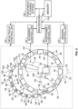
Fig. 2 is a schematic view of the particle therapy system ofFig. 1 . -
Fig. 3 is a front view of the particle therapy system ofFig. 1 mounted to a ceiling of a room. -
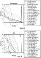
Fig. 4A shows dose volume histograms ("DVHs") for a simulated treatment of a paranasal tumor using an embodiment of a particle therapy system according to the disclosure compared to the same type of treatment performed using a gantry-based particle therapy system (dashed lines). -
Fig. 4B shows DVHs for another simulated treatment of a paranasal tumor using an embodiment of a particle therapy system according to the disclosure compared to the same type of treatment performed using a gantry-based particle therapy system (dashed lines). -
Fig. 4C shows DVHs for another simulated treatment of a paranasal tumor using an embodiment of a particle therapy system according to the disclosure compared to the same type of treatment performed using a gantry-based particle therapy system (dashed lines). -
Fig. 4D shows DVHs for another simulated treatment of a nasal cavity tumor with neck nodes using an embodiment of a particle therapy system according to the disclosure compared to the same type of treatment performed using a gantry-based particle therapy system (dashed lines). -
Fig. 4E shows DVHs for another simulated treatment of a suprasellar brain tumor using an embodiment of a particle therapy system according to the disclosure compared to the same type of treatment performed using a gantry-based particle therapy system (dashed lines). -
Fig. 4F shows DVHs for another simulated treatment of a central nervous system tumor using an embodiment of a particle therapy system according to the disclosure compared to the same type of treatment performed using a gantry-based particle therapy system (dashed lines). -
Fig. 4G shows DVHs for another simulated treatment of a chordoma using an embodiment of a particle therapy system according to the disclosure compared to the same type of treatment performed using a gantry-based particle therapy system (dashed lines). - Corresponding reference characters indicate corresponding parts throughout the several views. The exemplifications set out herein illustrate embodiments of the invention, and such exemplifications are not to be construed as limiting the scope of the invention in any manner.
- Generally, the present invention provides systems and methods for providing gantry-less particle therapy systems.
-
Figs. 1-3 illustrate non-limiting examples of aparticle therapy system 20 according to the present disclosure. Theparticle therapy system 20 includes, generally, a chargedparticle generating system 22 that generates an ion beam, abeam transport system 24 to focus and direct the ion beam, and abeam delivery device 26 to direct charged particles in the ion beam toward a patient for treatment. Theparticle therapy system 20 can operate using a variety of particles, including protons and heavier composite particles, which are used to then treat various types of cancers that may be present within a patient. Theparticle therapy system 20 can be used to perform proton therapy and heavy ion therapy, for example. In some non-limiting examples, theparticle therapy system 20 is a proton beam therapy system. - The charged
particle generating system 22 energizes particles, which can then be transported rapidly toward and into a patient to treat a variety of medical conditions, including many types of cancers. In accordance with the invention, the chargedparticle generating system 22 includes a particle energizer in the form of anion source 28, which is used to produce positively (or negatively) charged particles. In such embodiments, a gas source can feed gas (e.g., pure hydrogen) into theion source 28, where the electrons in the gas molecules can be removed. Theion source 28 can strip the gas molecules of electrons using lasers, catalysts, radiation, or other suitable ionization techniques to produce positively charged particles. As one example, theion source 28 may include a linear accelerator. As another example, theion source 28 may include an electron cyclotron resonance ("ECR") ion source. - An
injector 30 is coupled to theion source 28 to inject charged particles into thebeam transport system 24. Theinjector 30 may include, for example, a combination of septa and kicker magnets. The septa may be electrostatic or magnetic. Theinjector 30 can be configured to provide single-turn (e.g., fast) injection, multi-turn injection, charge-exchange injection, and so on. Hydrogen or carbon ions, for example, can be generated in theion source 28 and passed into theinjector 30, which accelerates the ions to form an ion beam (i.e., a charged particle beam). Theinjector 30 then directs the ion beam into thebeam transport system 24, where the ion beam can be further energized and eventually directed toward a patient. - The
beam transport system 24 is coupled to the chargedparticle generating system 22, and receives and direct the charged particles (e.g., the ion beam) outwardly away from theinjector 30 andion source 28. Thebeam transport system 24 includes abeam tube 32, which defines a beam track extending therethrough. For instance, thebeam tube 32 can be a metal pipe that, in accordance with the invention, is evacuated to a vacuum. Alternatively, in embodiments not being part of the invention, thebeam tube 32 can include sections or air or helium contained therein.Magnets 44 can be positioned about thebeam tube 32 to energize ion beams (e.g., by accelerating or heating the ions or charged particles), bend ion beams, and focus ion beams as they pass along the beam track. - The
beam transport system 24, and thus thebeam tube 32, includes three distinct segments that together define the beam track. Specifically, the beam track includes an energizingsegment 34 formed in afirst plane 35, an extractingsegment 36 formed in asecond plane 37 parallel and away from thefirst plane 35, and atransition segment 38 extending away from the energizingsegment 34 toward the extractingsegment 36. As will be described, the energizingsegment 34 circumscribes, or otherwise extends around, a volume to which the ion beam will be delivered by thebeam delivery device 26. The extractingsegment 36 terminates at aterminal end 39, at which thebeam delivery device 26 is coupled. In operation, an ion beam is delivered to the energizingsegment 34 from the chargedparticle generating system 22, where it is delivered to the extractingsegment 36 via thetransition segment 38. - As shown in
Fig. 1 , the energizingsegment 34 is, in accordance with the invention, positioned upon aplatform 40 proximate a mounting surface 42 (e.g., a floor, as shown inFig. 1 , a ceiling, as shown inFig. 3 , or a side wall of a room), and extends approximately parallel to the mountingsurface 42. The extractingsegment 36 is positioned away from the energizingsegment 34, and also extends parallel to the mountingsurface 42. - The energizing
segment 34 can be an accelerator. For example, the energizingsegment 34 can be a synchrotron having a substantially annular shape and defining a substantially circular outer perimeter. One or more radio frequency (RF)acceleration cavities 45 can be formed in the energizingsegment 34 as well. TheRF acceleration cavity 45 can include an RF applying electrode that is disposed on the circulating orbit of the accelerator and an RF power source that is in electrical communication with the RF applying electrode by way of a switch. In some aspects, one or more stacked ferrite components can be used to produce an electric field within the energizingsegment 34 to accelerate particles therein. - The substantially annular shape of the energizing
segment 34 can be defined by a radius of between about 2 meters and about 8 meters, for example. In some non-limiting examples, the energizingsegment 34 is defined by a radius of about 3 meters. Thebeam tube 32, along with theRF acceleration cavity 45 andmagnets 44, can define atreatment area 46 formed inwardly from the beam track. Accordingly, the energizingsegment 34 circumscribes or otherwise surrounds a volume containing thetreatment area 46, unlike gantry-based particle therapy systems where the synchrotron or cyclotron is located remotely (e.g., in a separate room) from the treatment area. In some instances, the energizingsegment 34 circumscribes a treatment isocenter. Apatient positioner 48 can be situated within thetreatment area 46. Thepatient positioner 48 can orient a patient relative to thebeam delivery device 26, which can further allow thebeam delivery device 26 to effectively supply an ion beam to different areas of the patient (e.g., the head or the stomach) to treat different types of medical conditions. In some non-limiting examples, animaging device 50 can also be positioned within thetreatment area 46. Theimaging device 50 can be used for imaging or locating the treatment target (e.g., a tumor) within a patient on thepatient positioner 48. Theimaging device 50 can be an X-ray machine or a CT scanner, for example. By placing thetreatment area 46 inward from the beam track, the footprint of theparticle therapy system 20 is reduced significantly. For example, the entireparticle therapy system 20 can be stored and operated within the same room. As one example, the entireparticle therapy system 20 can be contained within a 50 m2 room. - In use, the energizing
segment 34 is supplied with an ion beam from theinjector 30. If the energizingsegment 34 is designed as a synchrotron, magnets 44 (e.g., quadrupole and dipole magnets) can be positioned about thebeam tube 32 to steer the ion beam about the energizing segment 34 a number of times so that the ion beam repeatedly passes through theRF acceleration cavity 45, which increases the energy of the ion beam. Once the energy of the ion beam traveling in the energizingsegment 34 has reached a preselected, desired energy level (e.g., 100-300 MeV), the ion beam is extracted from the energizingsegment 34 into thetransition segment 38. Extraction may occur by way of bumping or kicking the ion beam to an outer trajectory so that it passes through a septum, or by way of resonance extraction. - The
transition segment 38 can extend tangentially and angularly away from the energizingsegment 34 to direct the ion beam out of the plane (e.g., the first plane 35) of the energizingsegment 34, to the elevation of the patient within the treatment area 46 (e.g., the elevation of the second plane 37). In accordance with the invention, thetransition segment 38 angles obtusely away from the energizingsegment 34 to form an angle of between about 115 degrees and about 155 degrees with respect to thefirst plane 35, which includes the energizingsegment 34. As shown inFig. 1 , thetransition segment 38 extends upwardly away from thefirst plane 35 at an angle of between about 115 degrees and about 155 degrees. - In an example not forming part of the present invention, the
first plane 35 and thesecond plane 37 can be coplanar, as shown inFig. 2 . The extractingsegment 136 can extend arcuately and radially inward from the energizingsegment 34 into thetreatment area 46 and toward thepatient positioner 48 and theimaging device 50. A plurality ofmagnets 55 can direct and focus the ion beam as it passes into thebeam delivery device 26 and toward a patient, as described below. In these aspects, which are not part of the present invention,transition segment 38 can extend inwardly away from the energizingsegment 34 within the same plane as the extractingsegment 136. In some aspects, not being part of the invention, thetransition 38 is omitted from thebeam tube 32 entirely. In another example not forming part of the present invention, thefirst plane 35 and thesecond plane 37 can be oriented approximately perpendicular to one another. In yet another example not forming part of the present invention, thefirst plane 35 is obliquely oriented (e.g., oriented nonparallel) with thesecond plane 37. In yet another example not forming part of the present invention, the extractingsegment 136 can be provided with a helical shape that extends along multiple planes. - The
transition segment 38 guides a highly energized ion beam from the energizingsegment 34 into the extractingsegment 36, which resides in thesecond plane 37 parallel and away from thefirst plane 35. The extractingsegment 36 can have an arcuate shape that extends, initially, outward beyond the circular outer perimeter of the energizingsegment 34. The extractingsegment 36 can then spiral inwardly within thesecond plane 37, such that the beam track extends back inside the circular outer perimeter of the energizingsegment 34, toward thetreatment area 46 and thepatient positioner 48 received inwardly from the energizingsegment 34. Thebeam delivery device 26 is coupled to the extractingsegment 36, which is positioned inward from the outer perimeter of the energizingsegment 34, within thetreatment area 46. In some non-limiting examples,legs 52 can extend away from the extractingsegment 36 to help support the extractingsegment 36 upon the mountingsurface 42 or theplatform 40. Thelegs 52 can extend perpendicularly between theplatform 40 and the extractingsegment 36, and can be coupled to the mountingsurface 42 orplatform 40 using fasteners, adhesives, or other mechanical couplings, for example. - The extracting
segment 36 directs highly energized ion beams from thetransition segment 38 into thebeam delivery device 26 using one or more magnets. For example, thebeam transport system 24 can include a plurality of magnets 55 (e.g., focusing magnets and steering magnets), which direct, energize, and shape the ion beam as it passes through thebeam transport system 24 toward thebeam delivery device 26. As an example, themagnets 55 can include focusing magnets that are quadrupole magnets, and steering magnets that are dipole magnets. Themagnets 55 are used to contain the ion beam within the beam track and to deliver the ion beam to thebeam delivery device 26 that is situated within thetreatment area 46. In some non-limiting examples, a magnetic system of dipoles, quadrupoles, sextupoles, octupoles, multipoles, or combinations of some or all of these magnet types can be used to both focus and direct highly energized ion beams toward thetreatment area 46. The placement and parameters (e.g., strength, number of magnetic poles) of themagnets 55 are designed to capture, with high efficiency, an ion beam extracted from the energizingsegment 34. Although specific magnetic system layouts that can direct ion beams effectively along the beam track are described, the magnetic systems can be optimized to include more or less magnets of varying polarity and strength to retrofit theparticle therapy system 20 for a room within a hospital. In the examples provided, theparticle therapy system 20 has been adapted to fit in a room conventionally used to house a linear accelerator ("LINAC") treatment system, within an area of about 7 meters by 7 meters. - With specific reference to
Fig. 2 , a specific combination ofmagnets 55 kept at room temperature or superconducting temperature can be used to extract and bend an ion beam toward thebeam delivery device 26 andtreatment area 46. AlthoughFig. 2 shows one example configuration for themagnets 55 in the extractingsegment 36, it will be appreciated by those skilled in the art that different configurations ofmagnets 55 along thebeam tube 32 in the extractingsegment 36 can be used depending on the geometries involved with the particular installation of theparticle therapy system 20. The ion beam can be first extracted from the energizingsegment 34 using twosuperconducting dipole magnets transition segment 38. Thesuperconducting dipole magnets Fig. 1 , downward inFig. 3 , or sideways, depending on the orientation of the particle therapy system 20) from the energizingsegment 34 and out of plane (i.e., the first plane 35) from the energizingsegment 34. In some non-limiting examples, the beam is bent upward at an angle of about 45 degrees. The twosuperconducting dipole magnets segment 36. - The extracting
segment 36 can include a number of magnets bending magnets, such as ten (as well as additional focusing magnets), for example, which are positioned about thesecond plane 37 to transport ion beams to a position of about 2 meters away from thepatient positioner 48 within thetreatment area 46. In this particular and non-limiting example, after being directed out of plane from the energizingsegment 34 and through thetransition segment 38, the ion beam passes through abeam drift tube 58 of about 0.6 meters before passing through afirst dipole magnet 60. Thefirst dipole magnet 60 can have a 0.6 meter dipole length that produces a 1.06 T magnetic field to bend the ion beam about 15 degrees. Next, the ion beam passes through another 0.7 meterbeam drift tube 62, which can also include an ion beam focusingquadrupole magnet 64. The ion beam is then transported to asecond dipole magnet 66, which has a 0.6 m dipole length and produces a 0.71 T magnetic field to bend the ion beam by about 10 degrees. Thesecond dipole magnet 66 can also include pole phase rotation. The ion beam can then pass through another 0.7 meterbeam drift tube 68 having another focusingquadrupole magnet 70, to athird dipole magnet 72. Like thesecond dipole magnet 66, thethird dipole magnet 72 can have pole phase rotation, as well as a dipole length of 0.6 meters that produces a 0.71 T magnetic field to bend the ion beam by about 10 degrees. Anotherbeam drift 74 of 0.6 meters extends from thethird dipole magnet 72, and includes a focusingquadrupole magnet 76 as well. - The ion beam then passes towards fourth and
fifth dipole magnets beam drift tube 80 that can include a focusingquadrupole magnet 82. The fourth andfifth dipole magnets beam drift tube 86 of about 0.9 meters extends away from thefifth dipole magnet 84, and can include two focusingquadrupole magnets sixth dipole magnet 92 having a 0.5 meter dipole length and producing a 0.85 T magnetic field is positioned away from thebeam drift tube 86. Thesixth dipole magnet 92 can include pole phase rotation, and can bend the ion beam by about 10 degrees. The ion beam then passes through anotherbeam drift 94 of 0.5 meters having a focusingquadrupole magnet 96, to aseventh dipole magnet 98. Theseventh dipole magnet 98 bends the ion beam by about 8 degrees, and has a 0.6 meter dipole length used to produce a magnetic field of 0.57 T. Again, theseventh dipole magnet 98 can have pole phase rotation. Abeam drift 100 of 0.3 meters having a focusingquadrupole magnet 102 extends from theseventh dipole magnet 98 toward theeighth dipole magnet 104. - In the example shown in
Fig. 2 , the eighth andninth dipole magnets beam drift tube 106 of 0.3 meters. The eighth andninth dipole magnets ninth dipole magnets ninth dipole magnets beam drift tube 110 of about 0.4 meters extends away from theninth dipole magnet 108 toward atenth dipole magnet 112. Thetenth dipole magnet 112 can include pole phase rotation and can have a dipole length of 0.6 meters. Thetenth dipole magnet 112 can produce a magnetic field of about 1.75 T, which bends the ion beam by about 25 degrees. - Once the ion beam has passed beyond the
tenth dipole magnet 112, it can be directed to thebeam delivery device 26 coupled to the extractingsegment 36 of the beam track. Thebeam delivery device 26 extends inwardly into thetreatment area 46 defined within the annular shape of the energizingsegment 34, and can act as a nozzle to direct a beam either in plane or at an angle relative to the plane in which the extractingsegment 36 of the beam track is arranged (i.e., the second plane 37). - The
beam delivery device 26 is designed to deliver precise dose distributions to a target volume within a patient. Thebeam delivery device 26 can include components that may either modify or monitor specific properties of an ion beam in accordance with a treatment plan. In some instances, thebeam delivery device 26 provides for pencil beam scanning of the ion beam. Thebeam delivery device 26 can include a beam spreading device to spread or otherwise modify the ion beam position and profile, a dispersive element to modify the ion beam energy, and/or a plurality of beam sensors to monitor such properties. The beam spreading device can transform the beam from the energizingsegment 34 and the extractingsegment 36 into a beam that is suitable for patient treatment. In some non-limiting examples, the beam spreading device can bend the beam up or down (or right or left) by about 15 degrees, which helps create different treatment angles for patients. Mechanical or magnetic elements can be used to spread the beam to the appropriate shape (e.g., to conform to the patient target), for example. In some aspects, thebeam delivery device 26 can include a range shifter. In some non-limiting examples, thebeam delivery device 26 can magnetically scan the ion beam and can provide pencil beam scanning for patient treatment. - As an example, the
beam delivery device 26 can include a nozzle at which thebeam tube 32 terminates. The nozzle generally includes an end through which the ion beam exits and is directed towards the patient. As noted, the nozzle can include components that can shape, steer, or otherwise modify or modulate the ion beam. For instance, the nozzle can include scanning electromagnets (e.g., wobbler magnets), a scatterer, a range shifter, a collimator (e.g., a multileaf collimator), a ridge filter, and so on. - The
particle therapy system 20 can be controlled by a central controller that includes aprocessor 114 and amemory 116 in communication with theprocessor 114. Abeam track controller 118 is in communication with theprocessor 114 and is configured to control operational parameters of the chargedparticle generating system 22, the energizingsegment 34, and the extractingsegment 36 of the beam track. Apositioner controller 120 can be in electrical communication with theprocessor 114, and can be used to control the position and orientation of thepatient positioner 48 within thetreatment area 46. Ascanning controller 122 can be in communication with theprocessor 114 to control thebeam delivery device 26. Animaging controller 124 can be in communication with theprocessor 114 as well, to control theimaging device 50. Thememory 116 can store treatment plans prescribed by atreatment planning system 126 that is in communication with theprocessor 114 and thememory 116, as well as control parameters or instructions to be delivered to thebeam track controller 118, thepositioner controller 120, theimaging controller 124, and/or thescanning controller 122. Thememory 116 may also store relevant patient information that can be accessed during a treatment session. - Using the combination of features described above, the
particle therapy system 20 has been simulated to effectively treat tumors in patients regardless of location. Using the scanning beam delivery modality (e.g., pencil beam scanning) incorporated by thebeam delivery device 26, optimal combinations of beam-to-patient geometries can be achieved without a gantry. Further, effective treatments can be achieved by theparticle therapy system 20, which is much smaller, more compact, and less expensive than conventional gantry-based systems currently being used to perform particle therapy. By locating the treatment area inside the outer perimeter of the beam track, substantial space is saved. - Various different treatment processes were simulated both using the
particle therapy system 20 and compared to simulation using a proton therapy system incorporating a gantry. Based on the results presented inFigs. 4A-4G , theparticle therapy system 20 proved as or nearly as effective as the proton therapy system incorporating a gantry in nearly every treatment simulation performed. As shown inFigs. 4A-4G , target dose levels can be delivered to various different tumor types using the gantry-less particle therapy system described in the present disclosure. The gantry-less system is thus able to deliver the same dose to the treatment volumes, while in some instance reducing the dose delivered to organs-at-risk. - While the invention has been described in connection with particular embodiments and examples, the invention is not necessarily so limited, and that numerous other are intended to be encompassed by the claims attached hereto.
- Various features and advantages of the invention are set forth in the following claims.
Claims (12)
- A particle therapy system for treating a patient, comprising:a charged particle generating system (22) comprising:an ion source (28);an injector (30) that injects an ion beam from the ion source (28) into a beam track;a beam transport system (24) defining the beam track and coupled to the charged particle generating system (22), the beam transport system (24) comprising:
a beam tube (32) evacuated to a vacuum and defining the beam track, the beam tube (32) comprising:an energizing segment (34) circumscribing a volume to which the ion beam is to be delivered, an extracting segment (36) terminating at a terminal end (39), and a transition segment (38) that connects the energizing segment (34) to the extracting segment (36), wherein the ion beam is received in the energizing segment (34) from the injector (30);a plurality of magnets (55) that adjust a trajectory of the ion beam in the beam tube (32) as the ion beam passes through each of the plurality of magnets (55);an acceleration cavity (45) that accelerates the ion beam as the ion beam passes through the acceleration cavity (45); anda beam delivery device (26) coupled to the terminal end (39) of the extracting segment (36) and positioned inward from an outer perimeter of the energizing segment (34), the beam delivery device (26) configured to direct the ion beam from the extracting segment (36) toward a treatment area (46) in the volume circumscribed by the energizing segment (34),whereinthe energizing segment (34) is positioned upon a platform (40) proximate a mounting surface (42) and extends in a first plane (35) that is approximately parallel to the mounting surface (42);the extracting segment (36) extends in a second plane (37) that is parallel to the first plane (35) and away from the first plane (35); and characterised in thatthe transition segment (38) angles obtusely away from the energizing segment (34) to form an angle of between about 115 degrees and about 155 degrees with respect to the first plane (35). - The system of claim 1, wherein the energizing segment (34) is defined by a substantially circular outer perimeter.
- The system of claim 2, wherein the extracting segment (36) has an arcuate shape.
- The system of claim 3, wherein the arcuate shape spirals radially inwardly toward the volume circumscribed by the energizing segment (34).
- The system of claim 1, wherein legs (52) extend away from the extracting segment (36) toward the first plane (35) to support the extracting segment (36).
- The system of claim 1, wherein the beam delivery device (26) includes a nozzle comprising scanning electromagnets that provide pencil beam scanning of the ion beam.
- The system of claim 1, wherein the plurality of magnets (55) comprises a plurality of bending magnets and a plurality of focusing magnets.
- The system of claim 1, wherein the plurality of magnets (55) includes dipole magnets (54; 56; 60; 66; 72; 78; 84; 92; 98; 104; 108; 112) and quadrupole magnets (64; 70; 82; 88; 90; 96; 102).
- The system of claim 1, wherein the energizing segment (34) comprises one of a synchrotron or a cyclotron.
- The system of claim 1, further comprising a patient positioner (48) situated inward from the outer perimeter.
- A method for creating a particle therapy system (20) for treating a patient, the method comprising:providing an ion source (28);connecting an injector (30) to the ion source (28) to extract an ion beam from the ion source (28);connecting a beam tube (32) to the injector (30) to receive the ion beam from the injector (30), the beam tube (32) defining a beam track that includes an annular portion circumscribing a volume, an arcuate portion, and a transition portion; andconnecting a beam delivery device (26) to the arcuate portion by the transition portion (38), and extending radially inward from the annular portion of the beam track into a patient treatment area (46) contained in the volume circumscribed by the annular portion,whereinthe annular portion is an energizing segment (34) that is positioned upon a platform (40) proximate a mounting surface (42)
and is formed in a first plane (35) that is approximately parallel to the mounting surface (42),the arcuate portion is an extracting segment that is formed in a second plane (37) that is parallel to the first plane (35) and away from the first plane (35), and characterised in thatthe transition portion extends from the first plane (35) to the second plane (37) and angles obtusely away from the annular portion to form an angle of between about 115 degrees and about 155 degrees with respect to the first plane (35). - The method of claim 11, wherein the arcuate portion is formed to spiral inwardly away from the transition portion.
Applications Claiming Priority (2)
| Application Number | Priority Date | Filing Date | Title |
|---|---|---|---|
| US201762500668P | 2017-05-03 | 2017-05-03 | |
| PCT/US2018/030791 WO2018204579A1 (en) | 2017-05-03 | 2018-05-03 | System and method for gantry-less particle therapy |
Publications (3)
| Publication Number | Publication Date |
|---|---|
| EP3618922A1 EP3618922A1 (en) | 2020-03-11 |
| EP3618922A4 EP3618922A4 (en) | 2021-02-24 |
| EP3618922B1 true EP3618922B1 (en) | 2025-04-02 |
Family
ID=64016689
Family Applications (1)
| Application Number | Title | Priority Date | Filing Date |
|---|---|---|---|
| EP18794458.2A Active EP3618922B1 (en) | 2017-05-03 | 2018-05-03 | System and method for gantry-less particle therapy |
Country Status (4)
| Country | Link |
|---|---|
| US (2) | US10880983B2 (en) |
| EP (1) | EP3618922B1 (en) |
| CN (1) | CN110799242B (en) |
| WO (1) | WO2018204579A1 (en) |
Families Citing this family (7)
| Publication number | Priority date | Publication date | Assignee | Title |
|---|---|---|---|---|
| WO2018204579A1 (en) * | 2017-05-03 | 2018-11-08 | The General Hospital Corporation | System and method for gantry-less particle therapy |
| CN110582234B (en) * | 2017-12-21 | 2023-03-10 | 中以康联国际医疗科技有限公司 | Radiation therapy systems and methods |
| US11857806B1 (en) | 2018-07-13 | 2024-01-02 | The United States Of America, As Represented By The Secretary Of The Navy | Luminescence-based method for precise delivery of ion beam therapy |
| JP2020051945A (en) * | 2018-09-27 | 2020-04-02 | 株式会社トプコン | Non-destructive inspection system, neutron irradiation source and neutron irradiation method |
| US12245355B2 (en) | 2021-02-19 | 2025-03-04 | Mevion Medical Systems, Inc. | Gantry for a particle therapy system |
| JP7072196B1 (en) * | 2021-07-29 | 2022-05-20 | 株式会社京都メディカルテクノロジー | Low-energy charged particle beam transport system and charged particle beam transport method in BNCT |
| AT527184A1 (en) * | 2023-05-11 | 2024-11-15 | Ebg Medaustron Gmbh | Particle therapy system and a method for operating such a |
Family Cites Families (23)
| Publication number | Priority date | Publication date | Assignee | Title |
|---|---|---|---|---|
| US4992746A (en) * | 1988-04-26 | 1991-02-12 | Acctek Associates | Apparatus for acceleration and application of negative ions and electrons |
| DE4411171A1 (en) * | 1994-03-30 | 1995-10-05 | Siemens Ag | Compact charged-particle accelerator for tumour therapy |
| JPH08148297A (en) | 1994-11-24 | 1996-06-07 | Mitsubishi Electric Corp | Charged particle device |
| JP3178381B2 (en) * | 1997-02-07 | 2001-06-18 | 株式会社日立製作所 | Charged particle irradiation device |
| JP3748426B2 (en) * | 2002-09-30 | 2006-02-22 | 株式会社日立製作所 | Medical particle beam irradiation equipment |
| US7529339B2 (en) * | 2003-12-12 | 2009-05-05 | University Of Western Ontario | Method and system for optimizing dose delivery of radiation |
| US7432516B2 (en) * | 2006-01-24 | 2008-10-07 | Brookhaven Science Associates, Llc | Rapid cycling medical synchrotron and beam delivery system |
| WO2008068691A2 (en) | 2006-12-04 | 2008-06-12 | Philips Intellectual Property & Standards Gmbh | X-ray tube with multiple electron sources and common electron deflection unit |
| WO2009142546A2 (en) * | 2008-05-22 | 2009-11-26 | Vladimir Yegorovich Balakin | Multi-field charged particle cancer therapy method and apparatus |
| US8901509B2 (en) | 2008-05-22 | 2014-12-02 | Vladimir Yegorovich Balakin | Multi-axis charged particle cancer therapy method and apparatus |
| US8089054B2 (en) * | 2008-05-22 | 2012-01-03 | Vladimir Balakin | Charged particle beam acceleration and extraction method and apparatus used in conjunction with a charged particle cancer therapy system |
| US7668292B1 (en) * | 2008-08-26 | 2010-02-23 | Siemens Medical Solutions Usa, Inc. | Patient setup error evaluation and error minimizing setup correction in association with radiotherapy treatment |
| AU2009341615B2 (en) * | 2009-03-04 | 2013-03-28 | Zakrytoe Aktsionernoe Obshchestvo Protom | Multi-field charged particle cancer therapy method and apparatus |
| EP2308561B1 (en) * | 2009-09-28 | 2011-06-15 | Ion Beam Applications | Compact gantry for particle therapy |
| US8431907B2 (en) | 2011-03-08 | 2013-04-30 | Mitsubishi Electric Corporation | Particle beam treatment device and irradiation dose setting method of the particle beam treatment device |
| US20130066134A1 (en) * | 2011-08-16 | 2013-03-14 | Mark Carol | Multiplexed Radiation Therapy |
| EP2581101A1 (en) | 2011-10-10 | 2013-04-17 | Iden Shams | Improvements in syringes |
| WO2014052734A1 (en) | 2012-09-28 | 2014-04-03 | Mevion Medical Systems, Inc. | Controlling particle therapy |
| WO2015070865A1 (en) * | 2013-11-14 | 2015-05-21 | Danfysik A/S | Particle therapy system |
| US9155912B2 (en) * | 2014-01-05 | 2015-10-13 | Xinsheng Cedric Yu | Method and system for stereotactic intensity-modulated arc therapy |
| JP6491867B2 (en) * | 2014-12-12 | 2019-03-27 | 国立研究開発法人量子科学技術研究開発機構 | Particle beam irradiation equipment |
| GB2551330A (en) | 2016-06-10 | 2017-12-20 | Lancaster Univ Business Enterprises Limited | Particle therapy delivery system |
| WO2018204579A1 (en) * | 2017-05-03 | 2018-11-08 | The General Hospital Corporation | System and method for gantry-less particle therapy |
-
2018
- 2018-05-03 WO PCT/US2018/030791 patent/WO2018204579A1/en not_active Ceased
- 2018-05-03 CN CN201880036940.2A patent/CN110799242B/en active Active
- 2018-05-03 US US16/607,664 patent/US10880983B2/en active Active
- 2018-05-03 EP EP18794458.2A patent/EP3618922B1/en active Active
-
2020
- 2020-11-05 US US17/090,809 patent/US11350516B2/en active Active
Also Published As
| Publication number | Publication date |
|---|---|
| CN110799242B (en) | 2022-08-30 |
| EP3618922A4 (en) | 2021-02-24 |
| WO2018204579A1 (en) | 2018-11-08 |
| US20210298162A1 (en) | 2021-09-23 |
| US11350516B2 (en) | 2022-05-31 |
| CN110799242A (en) | 2020-02-14 |
| US10880983B2 (en) | 2020-12-29 |
| EP3618922A1 (en) | 2020-03-11 |
| US20200196429A1 (en) | 2020-06-18 |
Similar Documents
| Publication | Publication Date | Title |
|---|---|---|
| US11350516B2 (en) | System and method for gantry-less particle therapy | |
| US4870287A (en) | Multi-station proton beam therapy system | |
| US9095705B2 (en) | Scanning systems for particle cancer therapy | |
| CA2343525A1 (en) | Ion beam therapy system and a method for operating the system | |
| JP7094375B2 (en) | Proton arc beam irradiation system | |
| CN105120954A (en) | Compact proton therapy system with energy selection onboard a rotatable gantry | |
| EP3308834B1 (en) | Particle therapy apparatus comprising an mri | |
| JP2013509277A (en) | Small isocentric gantry | |
| JP2015144846A (en) | Charged particle beam acceleration method and apparatus as part of a charged particle cancer treatment system | |
| MX2010012714A (en) | Charged particle cancer therapy beam path control method and apparatus. | |
| WO2017212290A1 (en) | Particle therapy delivery system | |
| US20250176093A1 (en) | Gantry for a particle therapy system | |
| WO2015071430A1 (en) | Particle therapy system | |
| US20140014849A1 (en) | Permanent Magnet Beam Transport System for Proton Radiation Therapy | |
| Mustapha et al. | Prospects for an advanced heavy ion therapy center in the Chicago area | |
| AU2021259040B2 (en) | Device for generating magnetic field and method for controlling same | |
| US20180104513A1 (en) | Method and apparatus for an ion beam accelerator and beam delivery system integrated on a rotating gantry | |
| Flanz et al. | Technology for proton therapy | |
| TWI869752B (en) | System comprising gantry configured for translational movement and method using the same | |
| TWI836518B (en) | Particle therapy system and gantry therefor | |
| Klein et al. | PROTON THERAPY: ACCELERATOR ASPECTS AND PROCEDURES |
Legal Events
| Date | Code | Title | Description |
|---|---|---|---|
| STAA | Information on the status of an ep patent application or granted ep patent |
Free format text: STATUS: THE INTERNATIONAL PUBLICATION HAS BEEN MADE |
|
| PUAI | Public reference made under article 153(3) epc to a published international application that has entered the european phase |
Free format text: ORIGINAL CODE: 0009012 |
|
| STAA | Information on the status of an ep patent application or granted ep patent |
Free format text: STATUS: REQUEST FOR EXAMINATION WAS MADE |
|
| 17P | Request for examination filed |
Effective date: 20191121 |
|
| AK | Designated contracting states |
Kind code of ref document: A1 Designated state(s): AL AT BE BG CH CY CZ DE DK EE ES FI FR GB GR HR HU IE IS IT LI LT LU LV MC MK MT NL NO PL PT RO RS SE SI SK SM TR |
|
| AX | Request for extension of the european patent |
Extension state: BA ME |
|
| DAV | Request for validation of the european patent (deleted) | ||
| DAX | Request for extension of the european patent (deleted) | ||
| RIN1 | Information on inventor provided before grant (corrected) |
Inventor name: FLANZ, JAY Inventor name: LU, HSIAO-MING Inventor name: YAN, SUSU Inventor name: BORTFELD, THOMAS |
|
| A4 | Supplementary search report drawn up and despatched |
Effective date: 20210122 |
|
| RIC1 | Information provided on ipc code assigned before grant |
Ipc: A61N 5/10 20060101ALI20210118BHEP Ipc: H05H 7/08 20060101ALI20210118BHEP Ipc: H05H 13/04 20060101ALI20210118BHEP Ipc: A61N 5/00 20060101AFI20210118BHEP Ipc: G21K 5/04 20060101ALI20210118BHEP |
|
| STAA | Information on the status of an ep patent application or granted ep patent |
Free format text: STATUS: EXAMINATION IS IN PROGRESS |
|
| 17Q | First examination report despatched |
Effective date: 20220701 |
|
| P01 | Opt-out of the competence of the unified patent court (upc) registered |
Effective date: 20230526 |
|
| GRAP | Despatch of communication of intention to grant a patent |
Free format text: ORIGINAL CODE: EPIDOSNIGR1 |
|
| STAA | Information on the status of an ep patent application or granted ep patent |
Free format text: STATUS: GRANT OF PATENT IS INTENDED |
|
| INTG | Intention to grant announced |
Effective date: 20241021 |
|
| GRAS | Grant fee paid |
Free format text: ORIGINAL CODE: EPIDOSNIGR3 |
|
| GRAA | (expected) grant |
Free format text: ORIGINAL CODE: 0009210 |
|
| STAA | Information on the status of an ep patent application or granted ep patent |
Free format text: STATUS: THE PATENT HAS BEEN GRANTED |
|
| AK | Designated contracting states |
Kind code of ref document: B1 Designated state(s): AL AT BE BG CH CY CZ DE DK EE ES FI FR GB GR HR HU IE IS IT LI LT LU LV MC MK MT NL NO PL PT RO RS SE SI SK SM TR |
|
| REG | Reference to a national code |
Ref country code: GB Ref legal event code: FG4D |
|
| REG | Reference to a national code |
Ref country code: CH Ref legal event code: EP |
|
| REG | Reference to a national code |
Ref country code: IE Ref legal event code: FG4D |
|
| REG | Reference to a national code |
Ref country code: DE Ref legal event code: R096 Ref document number: 602018080745 Country of ref document: DE |
|
| REG | Reference to a national code |
Ref country code: NL Ref legal event code: MP Effective date: 20250402 |
|
| PG25 | Lapsed in a contracting state [announced via postgrant information from national office to epo] |
Ref country code: NL Free format text: LAPSE BECAUSE OF FAILURE TO SUBMIT A TRANSLATION OF THE DESCRIPTION OR TO PAY THE FEE WITHIN THE PRESCRIBED TIME-LIMIT Effective date: 20250402 |
|
| REG | Reference to a national code |
Ref country code: AT Ref legal event code: MK05 Ref document number: 1780708 Country of ref document: AT Kind code of ref document: T Effective date: 20250402 |
|
| PG25 | Lapsed in a contracting state [announced via postgrant information from national office to epo] |
Ref country code: FI Free format text: LAPSE BECAUSE OF FAILURE TO SUBMIT A TRANSLATION OF THE DESCRIPTION OR TO PAY THE FEE WITHIN THE PRESCRIBED TIME-LIMIT Effective date: 20250402 Ref country code: PT Free format text: LAPSE BECAUSE OF FAILURE TO SUBMIT A TRANSLATION OF THE DESCRIPTION OR TO PAY THE FEE WITHIN THE PRESCRIBED TIME-LIMIT Effective date: 20250804 Ref country code: ES Free format text: LAPSE BECAUSE OF FAILURE TO SUBMIT A TRANSLATION OF THE DESCRIPTION OR TO PAY THE FEE WITHIN THE PRESCRIBED TIME-LIMIT Effective date: 20250402 |
|
| REG | Reference to a national code |
Ref country code: LT Ref legal event code: MG9D |
|
| PG25 | Lapsed in a contracting state [announced via postgrant information from national office to epo] |
Ref country code: GR Free format text: LAPSE BECAUSE OF FAILURE TO SUBMIT A TRANSLATION OF THE DESCRIPTION OR TO PAY THE FEE WITHIN THE PRESCRIBED TIME-LIMIT Effective date: 20250703 Ref country code: NO Free format text: LAPSE BECAUSE OF FAILURE TO SUBMIT A TRANSLATION OF THE DESCRIPTION OR TO PAY THE FEE WITHIN THE PRESCRIBED TIME-LIMIT Effective date: 20250702 |
|
| PG25 | Lapsed in a contracting state [announced via postgrant information from national office to epo] |
Ref country code: PL Free format text: LAPSE BECAUSE OF FAILURE TO SUBMIT A TRANSLATION OF THE DESCRIPTION OR TO PAY THE FEE WITHIN THE PRESCRIBED TIME-LIMIT Effective date: 20250402 |
|
| PG25 | Lapsed in a contracting state [announced via postgrant information from national office to epo] |
Ref country code: BG Free format text: LAPSE BECAUSE OF FAILURE TO SUBMIT A TRANSLATION OF THE DESCRIPTION OR TO PAY THE FEE WITHIN THE PRESCRIBED TIME-LIMIT Effective date: 20250402 |
|
| PG25 | Lapsed in a contracting state [announced via postgrant information from national office to epo] |
Ref country code: HR Free format text: LAPSE BECAUSE OF FAILURE TO SUBMIT A TRANSLATION OF THE DESCRIPTION OR TO PAY THE FEE WITHIN THE PRESCRIBED TIME-LIMIT Effective date: 20250402 |
|
| PG25 | Lapsed in a contracting state [announced via postgrant information from national office to epo] |
Ref country code: AT Free format text: LAPSE BECAUSE OF FAILURE TO SUBMIT A TRANSLATION OF THE DESCRIPTION OR TO PAY THE FEE WITHIN THE PRESCRIBED TIME-LIMIT Effective date: 20250402 |
|
| PG25 | Lapsed in a contracting state [announced via postgrant information from national office to epo] |
Ref country code: RS Free format text: LAPSE BECAUSE OF FAILURE TO SUBMIT A TRANSLATION OF THE DESCRIPTION OR TO PAY THE FEE WITHIN THE PRESCRIBED TIME-LIMIT Effective date: 20250702 |
|
| PG25 | Lapsed in a contracting state [announced via postgrant information from national office to epo] |
Ref country code: IS Free format text: LAPSE BECAUSE OF FAILURE TO SUBMIT A TRANSLATION OF THE DESCRIPTION OR TO PAY THE FEE WITHIN THE PRESCRIBED TIME-LIMIT Effective date: 20250802 |
|
| PG25 | Lapsed in a contracting state [announced via postgrant information from national office to epo] |
Ref country code: LV Free format text: LAPSE BECAUSE OF FAILURE TO SUBMIT A TRANSLATION OF THE DESCRIPTION OR TO PAY THE FEE WITHIN THE PRESCRIBED TIME-LIMIT Effective date: 20250402 |
|
| REG | Reference to a national code |
Ref country code: CH Ref legal event code: H13 Free format text: ST27 STATUS EVENT CODE: U-0-0-H10-H13 (AS PROVIDED BY THE NATIONAL OFFICE) Effective date: 20251223 |
|
| REG | Reference to a national code |
Ref country code: DE Ref legal event code: R097 Ref document number: 602018080745 Country of ref document: DE |
|
| PG25 | Lapsed in a contracting state [announced via postgrant information from national office to epo] |
Ref country code: SM Free format text: LAPSE BECAUSE OF FAILURE TO SUBMIT A TRANSLATION OF THE DESCRIPTION OR TO PAY THE FEE WITHIN THE PRESCRIBED TIME-LIMIT Effective date: 20250402 Ref country code: DK Free format text: LAPSE BECAUSE OF FAILURE TO SUBMIT A TRANSLATION OF THE DESCRIPTION OR TO PAY THE FEE WITHIN THE PRESCRIBED TIME-LIMIT Effective date: 20250402 |
|
| PG25 | Lapsed in a contracting state [announced via postgrant information from national office to epo] |
Ref country code: LU Free format text: LAPSE BECAUSE OF NON-PAYMENT OF DUE FEES Effective date: 20250503 |
|
| PG25 | Lapsed in a contracting state [announced via postgrant information from national office to epo] |
Ref country code: CH Free format text: LAPSE BECAUSE OF NON-PAYMENT OF DUE FEES Effective date: 20250531 |
|
| PG25 | Lapsed in a contracting state [announced via postgrant information from national office to epo] |
Ref country code: CZ Free format text: LAPSE BECAUSE OF FAILURE TO SUBMIT A TRANSLATION OF THE DESCRIPTION OR TO PAY THE FEE WITHIN THE PRESCRIBED TIME-LIMIT Effective date: 20250402 |
|
| PG25 | Lapsed in a contracting state [announced via postgrant information from national office to epo] |
Ref country code: EE Free format text: LAPSE BECAUSE OF FAILURE TO SUBMIT A TRANSLATION OF THE DESCRIPTION OR TO PAY THE FEE WITHIN THE PRESCRIBED TIME-LIMIT Effective date: 20250402 |
|
| PG25 | Lapsed in a contracting state [announced via postgrant information from national office to epo] |
Ref country code: RO Free format text: LAPSE BECAUSE OF FAILURE TO SUBMIT A TRANSLATION OF THE DESCRIPTION OR TO PAY THE FEE WITHIN THE PRESCRIBED TIME-LIMIT Effective date: 20250402 Ref country code: SK Free format text: LAPSE BECAUSE OF FAILURE TO SUBMIT A TRANSLATION OF THE DESCRIPTION OR TO PAY THE FEE WITHIN THE PRESCRIBED TIME-LIMIT Effective date: 20250402 |
|
| PG25 | Lapsed in a contracting state [announced via postgrant information from national office to epo] |
Ref country code: IT Free format text: LAPSE BECAUSE OF FAILURE TO SUBMIT A TRANSLATION OF THE DESCRIPTION OR TO PAY THE FEE WITHIN THE PRESCRIBED TIME-LIMIT Effective date: 20250402 |
|
| REG | Reference to a national code |
Ref country code: BE Ref legal event code: MM Effective date: 20250531 |
|
| PG25 | Lapsed in a contracting state [announced via postgrant information from national office to epo] |
Ref country code: MC Free format text: LAPSE BECAUSE OF FAILURE TO SUBMIT A TRANSLATION OF THE DESCRIPTION OR TO PAY THE FEE WITHIN THE PRESCRIBED TIME-LIMIT Effective date: 20250402 |
|
| PLBE | No opposition filed within time limit |
Free format text: ORIGINAL CODE: 0009261 |
|
| STAA | Information on the status of an ep patent application or granted ep patent |
Free format text: STATUS: NO OPPOSITION FILED WITHIN TIME LIMIT |
|
| REG | Reference to a national code |
Ref country code: CH Ref legal event code: L10 Free format text: ST27 STATUS EVENT CODE: U-0-0-L10-L00 (AS PROVIDED BY THE NATIONAL OFFICE) Effective date: 20260211 |
|
| 26N | No opposition filed |
Effective date: 20260105 |
|
| PG25 | Lapsed in a contracting state [announced via postgrant information from national office to epo] |
Ref country code: IE Free format text: LAPSE BECAUSE OF NON-PAYMENT OF DUE FEES Effective date: 20250503 |
|
| PG25 | Lapsed in a contracting state [announced via postgrant information from national office to epo] |
Ref country code: BE Free format text: LAPSE BECAUSE OF NON-PAYMENT OF DUE FEES Effective date: 20250531 |
|
| PG25 | Lapsed in a contracting state [announced via postgrant information from national office to epo] |
Ref country code: LT Free format text: LAPSE BECAUSE OF FAILURE TO SUBMIT A TRANSLATION OF THE DESCRIPTION OR TO PAY THE FEE WITHIN THE PRESCRIBED TIME-LIMIT Effective date: 20250402 |
|
| PGFP | Annual fee paid to national office [announced via postgrant information from national office to epo] |
Ref country code: GB Payment date: 20260527 Year of fee payment: 9 |
|
| PGFP | Annual fee paid to national office [announced via postgrant information from national office to epo] |
Ref country code: DE Payment date: 20260528 Year of fee payment: 9 |
|
| PGFP | Annual fee paid to national office [announced via postgrant information from national office to epo] |
Ref country code: FR Payment date: 20260525 Year of fee payment: 9 |
|
| PG25 | Lapsed in a contracting state [announced via postgrant information from national office to epo] |
Ref country code: SE Free format text: LAPSE BECAUSE OF FAILURE TO SUBMIT A TRANSLATION OF THE DESCRIPTION OR TO PAY THE FEE WITHIN THE PRESCRIBED TIME-LIMIT Effective date: 20250402 Ref country code: CY Free format text: LAPSE BECAUSE OF FAILURE TO SUBMIT A TRANSLATION OF THE DESCRIPTION OR TO PAY THE FEE WITHIN THE PRESCRIBED TIME-LIMIT Effective date: 20250402 |