EP3618893B1 - A syringe comprising a collapsible plunger - Google Patents
A syringe comprising a collapsible plunger Download PDFInfo
- Publication number
- EP3618893B1 EP3618893B1 EP18726225.8A EP18726225A EP3618893B1 EP 3618893 B1 EP3618893 B1 EP 3618893B1 EP 18726225 A EP18726225 A EP 18726225A EP 3618893 B1 EP3618893 B1 EP 3618893B1
- Authority
- EP
- European Patent Office
- Prior art keywords
- syringe
- contact
- contact portion
- force
- stress
- Prior art date
- Legal status (The legal status is an assumption and is not a legal conclusion. Google has not performed a legal analysis and makes no representation as to the accuracy of the status listed.)
- Active
Links
Images



Classifications
-
- A—HUMAN NECESSITIES
- A61—MEDICAL OR VETERINARY SCIENCE; HYGIENE
- A61M—DEVICES FOR INTRODUCING MEDIA INTO, OR ONTO, THE BODY; DEVICES FOR TRANSDUCING BODY MEDIA OR FOR TAKING MEDIA FROM THE BODY; DEVICES FOR PRODUCING OR ENDING SLEEP OR STUPOR
- A61M5/00—Devices for bringing media into the body in a subcutaneous, intra-vascular or intramuscular way; Accessories therefor, e.g. filling or cleaning devices, arm-rests
- A61M5/178—Syringes
- A61M5/31—Details
- A61M5/315—Pistons; Piston-rods; Guiding, blocking or restricting the movement of the rod or piston; Appliances on the rod for facilitating dosing ; Dosing mechanisms
- A61M5/31511—Piston or piston-rod constructions, e.g. connection of piston with piston-rod
- A61M5/31513—Piston constructions to improve sealing or sliding
-
- A—HUMAN NECESSITIES
- A61—MEDICAL OR VETERINARY SCIENCE; HYGIENE
- A61M—DEVICES FOR INTRODUCING MEDIA INTO, OR ONTO, THE BODY; DEVICES FOR TRANSDUCING BODY MEDIA OR FOR TAKING MEDIA FROM THE BODY; DEVICES FOR PRODUCING OR ENDING SLEEP OR STUPOR
- A61M5/00—Devices for bringing media into the body in a subcutaneous, intra-vascular or intramuscular way; Accessories therefor, e.g. filling or cleaning devices, arm-rests
- A61M5/178—Syringes
- A61M5/19—Syringes having more than one chamber, e.g. including a manifold coupling two parallelly aligned syringes through separate channels to a common discharge assembly
-
- A—HUMAN NECESSITIES
- A61—MEDICAL OR VETERINARY SCIENCE; HYGIENE
- A61M—DEVICES FOR INTRODUCING MEDIA INTO, OR ONTO, THE BODY; DEVICES FOR TRANSDUCING BODY MEDIA OR FOR TAKING MEDIA FROM THE BODY; DEVICES FOR PRODUCING OR ENDING SLEEP OR STUPOR
- A61M5/00—Devices for bringing media into the body in a subcutaneous, intra-vascular or intramuscular way; Accessories therefor, e.g. filling or cleaning devices, arm-rests
- A61M5/178—Syringes
- A61M5/31—Details
- A61M5/3129—Syringe barrels
- A61M5/3135—Syringe barrels characterised by constructional features of the proximal end
-
- A—HUMAN NECESSITIES
- A61—MEDICAL OR VETERINARY SCIENCE; HYGIENE
- A61M—DEVICES FOR INTRODUCING MEDIA INTO, OR ONTO, THE BODY; DEVICES FOR TRANSDUCING BODY MEDIA OR FOR TAKING MEDIA FROM THE BODY; DEVICES FOR PRODUCING OR ENDING SLEEP OR STUPOR
- A61M5/00—Devices for bringing media into the body in a subcutaneous, intra-vascular or intramuscular way; Accessories therefor, e.g. filling or cleaning devices, arm-rests
- A61M5/178—Syringes
- A61M5/31—Details
- A61M5/315—Pistons; Piston-rods; Guiding, blocking or restricting the movement of the rod or piston; Appliances on the rod for facilitating dosing ; Dosing mechanisms
- A61M5/31511—Piston or piston-rod constructions, e.g. connection of piston with piston-rod
-
- A—HUMAN NECESSITIES
- A61—MEDICAL OR VETERINARY SCIENCE; HYGIENE
- A61M—DEVICES FOR INTRODUCING MEDIA INTO, OR ONTO, THE BODY; DEVICES FOR TRANSDUCING BODY MEDIA OR FOR TAKING MEDIA FROM THE BODY; DEVICES FOR PRODUCING OR ENDING SLEEP OR STUPOR
- A61M5/00—Devices for bringing media into the body in a subcutaneous, intra-vascular or intramuscular way; Accessories therefor, e.g. filling or cleaning devices, arm-rests
- A61M5/178—Syringes
- A61M5/31—Details
- A61M5/315—Pistons; Piston-rods; Guiding, blocking or restricting the movement of the rod or piston; Appliances on the rod for facilitating dosing ; Dosing mechanisms
- A61M5/31511—Piston or piston-rod constructions, e.g. connection of piston with piston-rod
- A61M5/31515—Connection of piston with piston rod
-
- A—HUMAN NECESSITIES
- A61—MEDICAL OR VETERINARY SCIENCE; HYGIENE
- A61M—DEVICES FOR INTRODUCING MEDIA INTO, OR ONTO, THE BODY; DEVICES FOR TRANSDUCING BODY MEDIA OR FOR TAKING MEDIA FROM THE BODY; DEVICES FOR PRODUCING OR ENDING SLEEP OR STUPOR
- A61M5/00—Devices for bringing media into the body in a subcutaneous, intra-vascular or intramuscular way; Accessories therefor, e.g. filling or cleaning devices, arm-rests
- A61M5/178—Syringes
- A61M5/31—Details
- A61M2005/3128—Incorporating one-way valves, e.g. pressure-relief or non-return valves
Definitions
- the following description relates to a syringe.
- a syringe may include a plunger member and a barrel member.
- the syringe may be used to dispense a fluid stored in the barrel member of the syringe.
- the fluid may be dispensed by applying pressure to the plunger member of the syringe.
- the fluid may be dispensed regardless of the amount of force applied to the plunger member.
- US2007/185458 A1 , EP1166809 A1 , and US6712793 B1 disclose syringes including a telescopically collapsible plunger.
- a syringe terminates the dispensing of a fluid based on a force applied to a plunger member of the syringe.
- a syringe in some aspects, includes a barrel member and a plunger member.
- the barrel member defines an inner chamber
- the plunger member is sized to fit within the barrel member, and includes a contact portion, a top portion, and a bottom portion.
- the top portion includes a first end and a second end opposite the first end. The first end of the top portion is adapted to receive a first force co-axial with the barrel member during operation, and the second end of the top portion is in contact with the contact portion.
- the bottom portion includes a first end and a second end opposite the first end, and has a length greater than or equal to a length of the top portion.
- the first end of the bottom portion in contact with the contact portion, and the second end of the bottom portion divides the inner chamber into a first inner volume portion and a second inner volume portion.
- the contact portion permits the top portion to move independent of the bottom portion in response to a stress in the contact portion exceeding a critical stress.
- the stress in the contact portion is based on the first force applied to the first end of the top portion and a second force opposite the first force, the second force applied to the second end of the bottom portion by a fluid in the second inner volume portion of the inner chamber.
- a syringe plunger includes a contact portion, a first portion, and a second portion.
- the first portion includes a first end and a second end opposite the first end, with the second end of the first portion in contact with the contact portion.
- the second portion includes a first end and a second end opposite the first end, and has a length greater than or equal to a length of the first portion.
- the first end of the second portion is in contact with the contact portion.
- the contact portion permits the first portion to move independent of the second portion in response to a stress in the contact portion exceeding a critical stress.
- the stress in the contact portion is based on a first force applied to the first end of the first portion and a second force opposite the first force applied to the second end of the second portion.
- a method of operating a syringe includes receiving a first force at a top portion of a plunger member.
- the top portion is in contact with a contact portion of the plunger member, and the first force is co-axial with a barrel member of the syringe.
- the method also includes receiving a second force at a bottom portion of the plunger member, which is in contact with the contact portion and disposed within the barrel member.
- the second force is opposite the first force and caused by a fluid in the barrel member in response to the first force.
- the method further includes permitting the top portion to move independent of the bottom portion in response to a stress in the contact portion exceeding a critical stress. The stress in the contact portion is caused by the first force and the second force.
- a syringe terminates the dispensing of a fluid when a stress induced in a portion of a plunger member exceeds a critical stress.
- the syringe allows a first portion of the plunger member (e.g., a portion interacted with by an operator) to move independently of a second portion (e.g., a portion that is in contact with a fluid inside the barrel member of the syringe) when a force differential between a force applied to the plunger member and an opposing force (e.g., a force caused by the fluid inside the barrel member) exceeds a threshold.
- a plunger member of the syringe includes a contact portion that is in contact with a top and bottom portion of the plunger member. The contact portion is configured to allow the top portion of the plunger member to move independently of the bottom portion of the plunger member when a stress in the contact portion (caused by the opposing forces) exceeds a critical stress.
- a contact portion between top and bottom portions of a plunger member may experience a stress (e.g., tension or compression) when a force is applied to the top portion of the plunger member by an operator to dispense a fluid from the barrel member.
- a stress e.g., tension or compression
- an opposing force is applied to the bottom portion of the plunger member due at least partially to the viscosity of the fluid, inducing a stress in the contact portion.
- this stress exceeds a critical stress (e.g., a yield strength of the contact portion)
- the contact portion may mechanically fail (e.g., sever, split, tear, or rupture).
- the contact portion allows the top portion of the plunger member to move independently of the bottom portion, preventing the force applied to the top portion from being transferred to the bottom portion and preventing any further dispensing of the fluid inside the barrel member of the syringe.
- an end of the top portion of the plunger member may extend into the barrel member of the syringe.
- the length of the bottom portion is longer than the length of the top portion to prevent the top portion from transferring force to the bottom portion after the contact portion has mechanically failed.
- the syringe may prevent the dispensing of a fluid when a force needed to dispense the fluid becomes too great.
- the syringe may be used in an ophthalmologic surgical procedure where a polymer adhesive material cures inside the barrel member of the syringe during the surgical procedure. When the polymer has substantially cured, it may be unsafe to further dispense the polymer material in the surgical procedure.
- a syringe according to the present disclosure may prevent dispensing of the polymer once it has cured to a certain critical point, since the force required to further dispense the material would cause a stress in the plunger member that exceeds a critical stress (which may be determined based on properties of the polymer material, e.g., the viscosity at which the polymer material becomes unsafe to further dispense during the procedure).
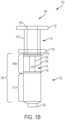
- FIGS. 1A-1B are diagrams showing perspective and side views, respectively, of an example syringe 100.
- the syringe 100 includes a barrel member 102 and a plunger member 104.
- the barrel member 102 defines an inner chamber 106, a barrel flange 130 at a first end, and an outlet 132 at a second end opposite the first end.
- the plunger member 104 (with the exception of the plunger flange 122) is sized to fit within barrel member 102 (e.g., inside the inner chamber 106).
- the inner chamber 106 is divided into a first inner volume portion 108 and a second inner volume portion 110.
- the second inner volume portion 110 may be filled with a fluid for dispensing.
- a polymer material e.g., a two-part polymer system that includes a solid portion (e.g., polyethylene glycol (PEG)) and a liquid portion (e.g., PEG-amine and water) that cure when mixed together
- PEG polyethylene glycol
- a liquid portion e.g., PEG-amine and water
- PEG-amine and water e.g., PEG-amine and water
- the plunger member 104 of the example syringe 100 includes a top portion 112, a bottom portion 114, and a contact portion 116 adapted to be in contact with each of the top portion 112 and the bottom portion 114.
- the contact portion 116 is integral with the bottom portion 114.
- the contact portion 116 is integral with the top portion 112 (e.g., as shown in FIGS. 3C-3D and described further below).
- the top portion 112, bottom portion 114, and the contact portion 116 are distinct and not integral with one another (e.g., as shown in FIGS. 3E-3F and described further below).
- the contact portion 116 may be composed of the same materials as the top and bottom portions 112, 114 (e.g., polypropylene), or may be composed of another suitable material (e.g., polyethelene, hard rubber, or another material).
- the top portion 112 includes a plunger flange 122 at a first end.
- the plunger flange 122 is adapted to receive a force during operation of the syringe 100.
- a second end of the top portion 112 (opposite the first end) is in contact with the contact portion 116.
- the first end of the top portion 112 may receive a force (e.g., via the plunger flange 122) that is co-axial or substantially co-axial with the barrel member 102 and the plunger member 104, causing the plunger member 104 to move further into the inner chamber 106, and dispensing a fluid in the second inner volume portion 110 from the outlet 132 of the barrel member 102.
- a first end of the bottom portion 114 is integral with the contact portion 116, and a second end of the bottom portion 114 (opposite the first end) includes a seal 118 that divides the inner chamber 106 into the first inner volume portion 108 and the second inner volume portion 110.
- the seal 118 may be any suitable material, such as, for example, a latex-free elastomer, polyethylene, polypropylene, or another type of material. The seal 118 may prevent fluid flow between the first inner volume portion 108 and the second inner volume portion 110.
- the contact portion 116 is designed to mechanically fail (e.g., sever, split, tear, or rupture) at a critical stress.
- the critical stress may be a pre-determined amount of stress that is based on the application of the syringe (e.g., which material is to be placed in the syringe for dispensing, the materials the syringe is composed of, etc.).
- the contact portion 116 may be a membrane designed to mechanically fail at a critical stress that is based on a viscosity of a fluid in the syringe (e.g., a polymer curing in the syringe, and becoming more viscous over time). In the example shown in FIG.
- the contact portion 116 is a solid membrane (e.g., as also shown in FIG. 4A and described further below).
- the critical stress is between one (1) and one thousand (1000) Newtons (N), such as, for example ten (10) Newtons (N), fifty (50) Newtons (N), one hundred (100) Newtons (N), or five hundred (500) Newtons (N).
- the contact portion 116 includes perforations (e.g., as shown in FIG. 4B and described further below).
- the contact portion 116 includes connecting members coupled between the top portion and the bottom portion (e.g., as shown in FIG. 4C and described further below). The contact portion 116 may be implemented in other ways.
- the contact portion 116 may be designed to fail upon experiencing a particular force applied to the top portion 112 (the stress induced in the contact portion 116 is based on the force applied to the top portion 112).
- the contact portion 116 is designed with a particular thickness based on the yield strength of the constituent material.
- the contact portion 116 is composed of WESTLAKE PLASTICS PROPYLUX polypropylene having a tensile yield strength of approximately 5310 pounds per square inch (psi), and the contact portion 116 comprises perforations (similar to the contact portion illustrated in FIG.
- the contact portion 116 may be designed to have a thickness of approximately 0.335 millimeters (mm) such that the contact portion 116 mechanically fails when experiencing a force of approximately ten (10) Newtons (N) at the top portion 112.
- the contact portion 116 may be designed to have a thickness of approximately 1.05 millimeters (mm) such that the contact portion 116 mechanically fails when experiencing a force of approximately one hundred (100) Newtons (N) at the top portion 112.
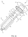
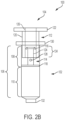
- FIGS. 2A-2B are diagrams showing perspective and side views, respectively, of the example syringe 100 of FIGS. 1A-1B after mechanical failure in the contact portion 116 of the plunger member 104.
- the contact portion 116 permits the top portion 112 to move independently of the bottom portion 114 when a stress in the contact portion-e.g., due to a force applied to the plunger flange 122 by an operator and an opposing force applied to the seal 118 by a viscous fluid in the second inner volume portion 110-exceeds a critical stress.
- the contact portion 116 mechanically fails as shown in FIGS.
- the top portion 112 extends into the inner chamber 106 without exerting a force upon the bottom portion 114.
- this causes the top portion 112 to overlap a portion of the bottom portion 114 as shown by the overlap region 134 in FIGS. 2A-2B .
- the bottom portion 114 is longer than the top portion 112. Accordingly, after mechanical failure in the contact portion 116, the top portion 112 cannot cause the bottom portion 114 to move and further dispense fluid from the outlet 132.
- the top portion 112 includes a tubular portion 120 and the plunger flange 122.
- the bottom portion 114 includes a cylindrical portion 124 between the contact portion 116 and the seal 118, and the diameter of the cylindrical portion 124 is less than the inner diameter of the tubular portion 120.
- the bottom portion 114 is generally tubular, the top portion 112 includes a cylindrical portion between its first and second ends, and the diameter of the cylindrical portion is less than the inner diameter of the bottom portion 114.
- Such configurations may allow for the top portion 112 to extend into the inner chamber 106 (e.g., the second end of the top portion 112 extending past the first end of the bottom portion) after failure of the contact portion 116.
- the length of the bottom portion 114 is greater than the length of the top portion 112 so that the second end of the top portion 112 cannot apply force to the seal 118 after the contact portion 116 has mechanically failed (since the plunger flange 122 will contact the barrel flange 130 before the second end of the top portion 112 makes contact with the seal 118).
- the top portion 112 defines an opening 126.
- the opening 126 is configured to allow fluid flow between the first inner volume portion 108 an exterior of the top portion 112 after mechanical failure in the contact portion 116.
- the bottom portion 114 also defines an opening 128 that is configured to allow fluid flow between the first inner volume portion 108 and the opening 126 after mechanical failure in the contact portion 116. Accordingly, when top portion 112 extends into the first inner volume portion 108 after mechanical failure in the contact portion 116, air in the first inner volume portion 108 may be expelled from the syringe 100, preventing pressure from being applied to the bottom portion 116 (which could allow further dispensing of a fluid in the second inner volume portion 110 from the outlet 132).
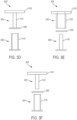
- FIGS. 3A-3F are diagrams showing side views of example plunger members 302 for use in a syringe.
- Each of the example plunger members 302 includes a top portion 304, a bottom portion 306, and a contact portion 308, and may be used in a syringe as described herein.
- any of the example plunger members 302 may be used in place of plunger member 104 in the syringe 100 of FIGS. 1A-1B and 2A-2B .
- the length of each top portion 304 is less than the length of the corresponding bottom portion 306.
- the example plunger member 302A of FIG. 3A includes a top portion 304A with a flange 310A and a tubular portion 312A, a bottom portion 306A with a cylindrical portion 314A, and a contact portion 308A that is integral with the bottom portion 306A.
- the inner diameter of the tubular portion 312A is greater than the diameter of the cylindrical portion 314A.
- the contact portion 308A may experience a stress in response to the force applied to the flange 310A (e.g., caused by a force differential between the force applied to the flange 310A and an opposing force applied to the bottom portion 306A, such as, for example, by a viscous fluid in a syringe). If the stress in the contact portion 308A exceeds a critical stress, the contact portion 308A may mechanically fail (e.g., sever, split, tear, or rupture) and allow the tubular portion 312A to extend past the cylindrical portion 314A, preventing the force applied to the flange 310A from being transferred to the bottom portion 306A.
- a stress in response to the force applied to the flange 310A e.g., caused by a force differential between the force applied to the flange 310A and an opposing force applied to the bottom portion 306A, such as, for example, by a viscous fluid in a syringe. If the stress
- the example plunger member 302B of FIG. 3B includes a top portion 304B with a flange 310B and a cylindrical portion 312B, a bottom portion 306B with a tubular portion 314B, and a contact portion 308B that is integral with the bottom portion 306B.
- the inner diameter of the tubular portion 314B is greater than the diameter of the cylindrical portion 312B.
- the contact portion 308B may experience a stress in response to the force applied to the flange 310B (e.g., caused by a force differential between the force applied to the flange 310B and an opposing force applied to the bottom portion 306B, such as, for example, by a viscous fluid in a syringe). If the stress in the contact portion 308B exceeds a critical stress, the contact portion 308B may mechanically fail (e.g., sever, split, tear, or rupture) and allow the cylindrical portion 312B to extend into the inner diameter of the tubular portion 314B, preventing the force applied to the flange 310B from being transferred to the bottom portion 306B.
- a stress in response to the force applied to the flange 310B e.g., caused by a force differential between the force applied to the flange 310B and an opposing force applied to the bottom portion 306B, such as, for example, by a viscous fluid in a syringe
- the example plunger member 302C of FIG. 3C includes a top portion 304C with a flange 310C and a tubular portion 312C, a bottom portion 306C with a cylindrical portion 314C, and a contact portion 308C that is integral with the top portion 304C.
- the inner diameter of the tubular portion 312C is greater than the diameter of the cylindrical portion 314C.
- the contact portion 308C may experience a stress in response to the force applied to the flange 310C (e.g., caused by a force differential between the force applied to the flange 310C and an opposing force applied to the bottom portion 306C, such as, for example, by a viscous fluid in a syringe). If the stress in the contact portion 308C exceeds a critical stress, the contact portion 308C may mechanically fail (e.g., sever, split, tear, or rupture) and allow the tubular portion 312C to extend past the cylindrical portion 314C, preventing the force applied to the flange 310C from being transferred to the bottom portion 306C.
- a stress in response to the force applied to the flange 310C e.g., caused by a force differential between the force applied to the flange 310C and an opposing force applied to the bottom portion 306C, such as, for example, by a viscous fluid in a syringe. If the stress
- the example plunger member 302D of FIG. 3D includes a top portion 304D with a flange 310D and a cylindrical portion 312D, a bottom portion 306D with a tubular portion 314D, and a contact portion 308D that is integral with the top portion 304D.
- the inner diameter of the tubular portion 314D is greater than the diameter of the cylindrical portion 312D.
- the contact portion 308D may experience a stress in response to the force applied to the flange 310D (e.g., caused by a force differential between the force applied to the flange 310D and an opposing force applied to the bottom portion 306D, such as, for example, by a viscous fluid in a syringe). If the stress in the contact portion 308D exceeds a critical stress, the contact portion 308D may mechanically fail (e.g., sever, split, tear, or rupture) and allow the cylindrical portion 312D to extend into the inner diameter of the tubular portion 314D, preventing the force applied to the flange 310D from being transferred to the bottom portion 306D.
- a stress in response to the force applied to the flange 310D e.g., caused by a force differential between the force applied to the flange 310D and an opposing force applied to the bottom portion 306D, such as, for example, by a viscous fluid in a syringe
- the example plunger member 302E of FIG. 3E includes a top portion 304E with a flange 310E and a tubular portion 312E, a bottom portion 306E with a cylindrical portion 314E, and a contact portion 308E that is distinct from the top portion 304E and the bottom portion 306E.
- the inner diameter of the tubular portion 312E is greater than the diameter of the cylindrical portion 314E.
- the contact portion 308E may experience a stress in response to the force applied to the flange 310E (e.g., caused by a force differential between the force applied to the flange 310E and an opposing force applied to the bottom portion 306E, such as, for example, by a viscous fluid in a syringe). If the stress in the contact portion 308E exceeds a critical stress, the contact portion 308E may mechanically fail (e.g., sever, split, tear, or rupture) and allow the tubular portion 314E to extend past the cylindrical portion 314E, preventing the force applied to the flange 310E from being transferred to the bottom portion 306E.
- a stress in response to the force applied to the flange 310E e.g., caused by a force differential between the force applied to the flange 310E and an opposing force applied to the bottom portion 306E, such as, for example, by a viscous fluid in a syringe. If the stress
- the example plunger member 302F of FIG. 3F includes a top portion 304F with a flange 310F and a cylindrical portion 312F, a bottom portion 306F with a tubular portion 314F, and a contact portion 308F that is distinct from the top portion 304F and the bottom portion 306F.
- the inner diameter of the tubular portion 314F is greater than the diameter of the cylindrical portion 312f.
- the contact portion 308F may experience a stress in response to the force applied to the flange 310F (e.g., caused by a force differential between the force applied to the flange 310F and an opposing force applied to the bottom portion 306F, such as, for example, by a viscous fluid in a syringe). If the stress in the contact portion 308F exceeds a critical stress, the contact portion 308F may mechanically fail (e.g., sever, split, tear, or rupture) and allow the cylindrical portion 312F to extend into the inner diameter of the tubular portion 314F, preventing the force applied to the flange 310F from being transferred to the bottom portion 306F.
- a stress in response to the force applied to the flange 310F e.g., caused by a force differential between the force applied to the flange 310F and an opposing force applied to the bottom portion 306F, such as, for example, by a viscous fluid in a syringe
- FIGS. 4A- 4C are diagrams showing perspective views of example contact portion configurations for plunger members 402.
- Each of the example plunger members 402 includes a top portion 404, a bottom portion 406, and a contact portion 308, and may be used in a syringe as described herein.
- any of the example plunger members 402 may be used in place of plunger member 104 in the syringe 100 of FIGS. 1A-1B and 2A-2B .
- the example plunger member 402A of FIG. 4A includes a tubular top portion 404A, a cylindrical bottom portion 406A, and a contact portion 408A that is integral with the bottom portion 406A.
- the inner diameter of the top portion 404A is greater than the diameter of the bottom portion 406A
- the contact portion 408A is a solid membrane.
- the membrane may be configured to mechanically fail upon experiencing a stress greater than a pre-determined critical stress. In some instances, the membrane is designed with a particular thickness that is based upon the yield strength of the composition material.
- the example plunger member 402B of FIG. 4B includes a tubular top portion 404B, a cylindrical bottom portion 406B, and a contact portion 408B that is integral with the top portion 404B.
- the inner diameter of the top portion 404B is greater than the diameter of the bottom portion 406B
- the contact portion 408A is a membrane with perforations 410.
- the perforations 410 of the contact portion 408B may be configured to mechanically fail upon experiencing a stress greater than a pre-determined critical stress (e.g., a stress greater than ten (10) Newtons (N)), for example.
- the example plunger member 402C of FIG. 4C includes a tubular top portion 404C, a cylindrical bottom portion 406C, and a contact portion 408C that includes multiple connecting members 412 coupled between the top portion 404C and the bottom portion 406C.
- the inner diameter of the top portion 404C is greater than the diameter of the bottom portion 406C.
- the connecting member 412 may be configured to mechanically fail upon experiencing a stress greater than a pre-determined critical stress.
- the connecting members 412 may be cylindrical and designed with a particular diameter that is based upon the yield strength of the composition material.
- the connecting members 412 may be configured to mechanically fail upon experiencing a stress greater than ten (10) Newtons (N), for example.
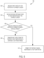
- FIG. 5 is a flow diagram showing an example process 500 for operating a syringe.
- the process 500 may be used to operate a syringe according to the present disclosure.
- the process 500 may be used to operate the syringe 100 of FIGS. 1A-1B and 2A-2B or another type of syringe that includes a contact portion configured to mechanically fail upon experiencing a stress that exceeds a critical stress.
- a top portion of a syringe plunger receives a first force.
- the first force may be applied by an operator to a flange of the syringe plunger, or to another portion of the syringe plunger.
- the top portion of the syringe plunger may be coupled to a bottom portion of the syringe plunger via a contact portion.
- the first force may be co-axial or substantially co-axial with the plunger and barrel of the syringe.
- the first force may be applied to the plunger flange 122 by an operator in a direction toward the barrel member 102 (the downward direction when referring to FIGS. 1B and 2B ), and may be co-axial with the plunger member 104 and the barrel member 102.
- the bottom portion of the syringe plunger receives a second force from a fluid in the barrel of the syringe.
- the second force may be in response to the first force and opposite the first force received at 502.
- the second force may be due to the viscosity of the fluid, a force caused by pressure in the fluid at an outlet of the barrel of the syringe, friction between the plunger and the barrel of the syringe, or a combination thereof.
- the second force may be applied to the seal 118 by a fluid in the second inner volume portion 110 of the barrel member 102 (the upward direction when referring to FIGS. 1B and 2B ), and may be co-axial with the plunger member 104 and the barrel member 102.
- a stress is induced in a contact portion of the syringe plunger.
- the stress may be a tension, compression, or other type of stress incident upon the contact portion, and may be caused by the first force received at 502 and the second force received at 504.
- the first and second forces may act upon the contact portion 116 of the plunger member 104 and cause a tension in the contact portion 116.
- the first and second forces may cause a compression or another type of stress in the contact portion 116.
- the stress in the contact portion may also be caused by other internal forces acting inside the syringe as well.
- the process proceeds to 508, where the net force of the first and second forces in the co-axial direction is transferred to a fluid in the syringe (e.g., to dispense the fluid from the syringe).
- the top portion 112 may transfer a force (the net of the first and second forces) to the bottom portion 114 through the contact portion 116, which in turn transfers the force to a fluid in the second inner volume portion 110 of the syringe 100 to dispense the fluid from the outlet 132.
- the process proceeds to 510, where the top portion of the plunger member is permitted to move independent of the bottom portion of the plunger member.
- an end of the top portion may be permitted to extend past an end of the bottom portion (e.g., as shown in FIGS. 2A-2B ).
- the top portion may be permitted to move independent of the bottom portion due to a mechanical failure in the contact portion of the syringe plunger. For example, referring to the example syringe 100 of FIGS.
- the contact portion 116 may break in response to a stress induced therein being greater than the critical stress, and may accordingly allow the lower end of the top portion 112 to extend past the upper end of the bottom portion 114, and into the first inner volume portion 108 of the inner chamber 106. When this happens, the force applied to the top portion 112 may be prevented from being transferred to the bottom portion 114, preventing any fluid in the second inner volume portion 110 from being dispensed from the outlet 132.
Landscapes
- Health & Medical Sciences (AREA)
- Vascular Medicine (AREA)
- Engineering & Computer Science (AREA)
- Anesthesiology (AREA)
- Biomedical Technology (AREA)
- Heart & Thoracic Surgery (AREA)
- Hematology (AREA)
- Life Sciences & Earth Sciences (AREA)
- Animal Behavior & Ethology (AREA)
- General Health & Medical Sciences (AREA)
- Public Health (AREA)
- Veterinary Medicine (AREA)
- Infusion, Injection, And Reservoir Apparatuses (AREA)
Description
- The following description relates to a syringe.
- A syringe may include a plunger member and a barrel member. The syringe may be used to dispense a fluid stored in the barrel member of the syringe. The fluid may be dispensed by applying pressure to the plunger member of the syringe. In typical syringes, the fluid may be dispensed regardless of the amount of force applied to the plunger member.
-
US2007/185458 A1 ,EP1166809 A1 , andUS6712793 B1 disclose syringes including a telescopically collapsible plunger. - The invention is set out in the appended set of claims.
- In a general aspect, a syringe terminates the dispensing of a fluid based on a force applied to a plunger member of the syringe.
- In some aspects, a syringe includes a barrel member and a plunger member. The barrel member defines an inner chamber, and the plunger member is sized to fit within the barrel member, and includes a contact portion, a top portion, and a bottom portion. The top portion includes a first end and a second end opposite the first end. The first end of the top portion is adapted to receive a first force co-axial with the barrel member during operation, and the second end of the top portion is in contact with the contact portion. The bottom portion includes a first end and a second end opposite the first end, and has a length greater than or equal to a length of the top portion. The first end of the bottom portion in contact with the contact portion, and the second end of the bottom portion divides the inner chamber into a first inner volume portion and a second inner volume portion. The contact portion permits the top portion to move independent of the bottom portion in response to a stress in the contact portion exceeding a critical stress. The stress in the contact portion is based on the first force applied to the first end of the top portion and a second force opposite the first force, the second force applied to the second end of the bottom portion by a fluid in the second inner volume portion of the inner chamber.
- In some aspects, a syringe plunger includes a contact portion, a first portion, and a second portion. The first portion includes a first end and a second end opposite the first end, with the second end of the first portion in contact with the contact portion. The second portion includes a first end and a second end opposite the first end, and has a length greater than or equal to a length of the first portion. The first end of the second portion is in contact with the contact portion. The contact portion permits the first portion to move independent of the second portion in response to a stress in the contact portion exceeding a critical stress. The stress in the contact portion is based on a first force applied to the first end of the first portion and a second force opposite the first force applied to the second end of the second portion.
- In some aspects, a method of operating a syringe includes receiving a first force at a top portion of a plunger member. The top portion is in contact with a contact portion of the plunger member, and the first force is co-axial with a barrel member of the syringe. The method also includes receiving a second force at a bottom portion of the plunger member, which is in contact with the contact portion and disposed within the barrel member. The second force is opposite the first force and caused by a fluid in the barrel member in response to the first force. The method further includes permitting the top portion to move independent of the bottom portion in response to a stress in the contact portion exceeding a critical stress. The stress in the contact portion is caused by the first force and the second force.
- The details of one or more implementations are set forth in the accompanying drawings and the description below. Other features, objects, and advantages will be apparent from the description and drawings, and from the claims.
-
-
FIGS. 1A-1B are diagrams showing perspective and side views, respectively, of an example syringe. -
FIGS. 2A-2B are diagrams showing perspective and side views, respectively, of the example syringe ofFIGS. 1A-1B after mechanical failure in the contact portion of the plunger member. -
FIGS. 3A- 3F are diagrams showing side views of example plunger members for use in a syringe. -
FIGS. 4A- 4C are diagrams showing perspective views of example contact portion configurations for plunger members. -
FIG. 5 is a flow diagram showing an example process for operating a syringe. - A syringe terminates the dispensing of a fluid when a stress induced in a portion of a plunger member exceeds a critical stress. The syringe allows a first portion of the plunger member (e.g., a portion interacted with by an operator) to move independently of a second portion (e.g., a portion that is in contact with a fluid inside the barrel member of the syringe) when a force differential between a force applied to the plunger member and an opposing force (e.g., a force caused by the fluid inside the barrel member) exceeds a threshold. A plunger member of the syringe includes a contact portion that is in contact with a top and bottom portion of the plunger member. The contact portion is configured to allow the top portion of the plunger member to move independently of the bottom portion of the plunger member when a stress in the contact portion (caused by the opposing forces) exceeds a critical stress.
- A contact portion between top and bottom portions of a plunger member may experience a stress (e.g., tension or compression) when a force is applied to the top portion of the plunger member by an operator to dispense a fluid from the barrel member. When the force is applied to the top portion, an opposing force is applied to the bottom portion of the plunger member due at least partially to the viscosity of the fluid, inducing a stress in the contact portion. When this stress exceeds a critical stress (e.g., a yield strength of the contact portion), the contact portion may mechanically fail (e.g., sever, split, tear, or rupture). When this occurs, the contact portion allows the top portion of the plunger member to move independently of the bottom portion, preventing the force applied to the top portion from being transferred to the bottom portion and preventing any further dispensing of the fluid inside the barrel member of the syringe. After the contact portion has mechanically failed, an end of the top portion of the plunger member may extend into the barrel member of the syringe. The length of the bottom portion is longer than the length of the top portion to prevent the top portion from transferring force to the bottom portion after the contact portion has mechanically failed.
- Aspects of what is described here may provide certain advantages. In some aspects, for example, the syringe may prevent the dispensing of a fluid when a force needed to dispense the fluid becomes too great. For example, the syringe may be used in an ophthalmologic surgical procedure where a polymer adhesive material cures inside the barrel member of the syringe during the surgical procedure. When the polymer has substantially cured, it may be unsafe to further dispense the polymer material in the surgical procedure. A syringe according to the present disclosure may prevent dispensing of the polymer once it has cured to a certain critical point, since the force required to further dispense the material would cause a stress in the plunger member that exceeds a critical stress (which may be determined based on properties of the polymer material, e.g., the viscosity at which the polymer material becomes unsafe to further dispense during the procedure).
-
FIGS. 1A-1B are diagrams showing perspective and side views, respectively, of anexample syringe 100. Thesyringe 100 includes abarrel member 102 and aplunger member 104. Thebarrel member 102 defines aninner chamber 106, abarrel flange 130 at a first end, and anoutlet 132 at a second end opposite the first end. The plunger member 104 (with the exception of the plunger flange 122) is sized to fit within barrel member 102 (e.g., inside the inner chamber 106). When theplunger member 104 is at least partially disposed within theinner chamber 106 as shown in the example views ofFIGS 1A-1B , theinner chamber 106 is divided into a firstinner volume portion 108 and a secondinner volume portion 110. In some instances, the secondinner volume portion 110 may be filled with a fluid for dispensing. For example, a polymer material (e.g., a two-part polymer system that includes a solid portion (e.g., polyethylene glycol (PEG)) and a liquid portion (e.g., PEG-amine and water) that cure when mixed together) may be placed inside the secondinner volume portion 110 for dispensing during an ophthalmologic surgical procedure, or another type of fluid may be placed in the secondinner volume portion 110. Each of thebarrel member 102 and theplunger member 104 may be composed of any suitable material, such as, for example, polypropylene, polyethelene, glass, or another type of material. In some instances, portions of the barrel member 102 (e.g., the walls of the inner chamber 106) are coated with a silicone lubricant. - The
plunger member 104 of theexample syringe 100 includes atop portion 112, abottom portion 114, and acontact portion 116 adapted to be in contact with each of thetop portion 112 and thebottom portion 114. In the example shown inFIG. 1A (and also inFIGS. 3A-3B and described further below), thecontact portion 116 is integral with thebottom portion 114. In some implementations, thecontact portion 116 is integral with the top portion 112 (e.g., as shown inFIGS. 3C-3D and described further below). In some implementations, thetop portion 112,bottom portion 114, and thecontact portion 116 are distinct and not integral with one another (e.g., as shown inFIGS. 3E-3F and described further below). Thecontact portion 116 may be composed of the same materials as the top andbottom portions 112, 114 (e.g., polypropylene), or may be composed of another suitable material (e.g., polyethelene, hard rubber, or another material). - In the example shown, the
top portion 112 includes aplunger flange 122 at a first end. Theplunger flange 122 is adapted to receive a force during operation of thesyringe 100. A second end of the top portion 112 (opposite the first end) is in contact with thecontact portion 116. During normal operation, the first end of thetop portion 112 may receive a force (e.g., via the plunger flange 122) that is co-axial or substantially co-axial with thebarrel member 102 and theplunger member 104, causing theplunger member 104 to move further into theinner chamber 106, and dispensing a fluid in the secondinner volume portion 110 from theoutlet 132 of thebarrel member 102. In the example shown, a first end of thebottom portion 114 is integral with thecontact portion 116, and a second end of the bottom portion 114 (opposite the first end) includes aseal 118 that divides theinner chamber 106 into the firstinner volume portion 108 and the secondinner volume portion 110. Theseal 118 may be any suitable material, such as, for example, a latex-free elastomer, polyethylene, polypropylene, or another type of material. Theseal 118 may prevent fluid flow between the firstinner volume portion 108 and the secondinner volume portion 110. - In some implementations, the
contact portion 116 is designed to mechanically fail (e.g., sever, split, tear, or rupture) at a critical stress. The critical stress may be a pre-determined amount of stress that is based on the application of the syringe (e.g., which material is to be placed in the syringe for dispensing, the materials the syringe is composed of, etc.). For example, thecontact portion 116 may be a membrane designed to mechanically fail at a critical stress that is based on a viscosity of a fluid in the syringe (e.g., a polymer curing in the syringe, and becoming more viscous over time). In the example shown inFIG. 1A , thecontact portion 116 is a solid membrane (e.g., as also shown inFIG. 4A and described further below). In some instances, the critical stress is between one (1) and one thousand (1000) Newtons (N), such as, for example ten (10) Newtons (N), fifty (50) Newtons (N), one hundred (100) Newtons (N), or five hundred (500) Newtons (N). In some implementations, thecontact portion 116 includes perforations (e.g., as shown inFIG. 4B and described further below). In some implementations, thecontact portion 116 includes connecting members coupled between the top portion and the bottom portion (e.g., as shown inFIG. 4C and described further below). Thecontact portion 116 may be implemented in other ways. - The
contact portion 116 may be designed to fail upon experiencing a particular force applied to the top portion 112 (the stress induced in thecontact portion 116 is based on the force applied to the top portion 112). For instance, in some implementations, thecontact portion 116 is designed with a particular thickness based on the yield strength of the constituent material. As an example, where thecontact portion 116 is composed of WESTLAKE PLASTICS PROPYLUX polypropylene having a tensile yield strength of approximately 5310 pounds per square inch (psi), and thecontact portion 116 comprises perforations (similar to the contact portion illustrated inFIG. 4B ), thecontact portion 116 may be designed to have a thickness of approximately 0.335 millimeters (mm) such that thecontact portion 116 mechanically fails when experiencing a force of approximately ten (10) Newtons (N) at thetop portion 112. Using the same example, thecontact portion 116 may be designed to have a thickness of approximately 1.05 millimeters (mm) such that thecontact portion 116 mechanically fails when experiencing a force of approximately one hundred (100) Newtons (N) at thetop portion 112. -
FIGS. 2A-2B are diagrams showing perspective and side views, respectively, of theexample syringe 100 ofFIGS. 1A-1B after mechanical failure in thecontact portion 116 of theplunger member 104. In the example shown, thecontact portion 116 permits thetop portion 112 to move independently of thebottom portion 114 when a stress in the contact portion-e.g., due to a force applied to theplunger flange 122 by an operator and an opposing force applied to theseal 118 by a viscous fluid in the second inner volume portion 110-exceeds a critical stress. When this happens, thecontact portion 116 mechanically fails as shown inFIGS. 2A-2B , and thetop portion 112 extends into theinner chamber 106 without exerting a force upon thebottom portion 114. In the example shown, this causes thetop portion 112 to overlap a portion of thebottom portion 114 as shown by theoverlap region 134 inFIGS. 2A-2B . In the example shown, thebottom portion 114 is longer than thetop portion 112. Accordingly, after mechanical failure in thecontact portion 116, thetop portion 112 cannot cause thebottom portion 114 to move and further dispense fluid from theoutlet 132. - In the example shown, the
top portion 112 includes atubular portion 120 and theplunger flange 122. Thebottom portion 114 includes acylindrical portion 124 between thecontact portion 116 and theseal 118, and the diameter of thecylindrical portion 124 is less than the inner diameter of thetubular portion 120. In some implementations, however (e.g., as shown inFIGS. 3B ,3D, and 3F ), thebottom portion 114 is generally tubular, thetop portion 112 includes a cylindrical portion between its first and second ends, and the diameter of the cylindrical portion is less than the inner diameter of thebottom portion 114. Such configurations may allow for thetop portion 112 to extend into the inner chamber 106 (e.g., the second end of thetop portion 112 extending past the first end of the bottom portion) after failure of thecontact portion 116. In the example shown, the length of thebottom portion 114 is greater than the length of thetop portion 112 so that the second end of thetop portion 112 cannot apply force to theseal 118 after thecontact portion 116 has mechanically failed (since theplunger flange 122 will contact thebarrel flange 130 before the second end of thetop portion 112 makes contact with the seal 118). - In the example shown, the
top portion 112 defines anopening 126. Theopening 126 is configured to allow fluid flow between the firstinner volume portion 108 an exterior of thetop portion 112 after mechanical failure in thecontact portion 116. Furthermore, in the example shown, thebottom portion 114 also defines anopening 128 that is configured to allow fluid flow between the firstinner volume portion 108 and theopening 126 after mechanical failure in thecontact portion 116. Accordingly, whentop portion 112 extends into the firstinner volume portion 108 after mechanical failure in thecontact portion 116, air in the firstinner volume portion 108 may be expelled from thesyringe 100, preventing pressure from being applied to the bottom portion 116 (which could allow further dispensing of a fluid in the secondinner volume portion 110 from the outlet 132). -
FIGS. 3A-3F are diagrams showing side views of example plunger members 302 for use in a syringe. Each of the example plunger members 302 includes atop portion 304, abottom portion 306, and a contact portion 308, and may be used in a syringe as described herein. For example, any of the example plunger members 302 may be used in place ofplunger member 104 in thesyringe 100 ofFIGS. 1A-1B and2A-2B . In the examples shown, the length of eachtop portion 304 is less than the length of thecorresponding bottom portion 306. - The
example plunger member 302A ofFIG. 3A includes atop portion 304A with aflange 310A and atubular portion 312A, abottom portion 306A with acylindrical portion 314A, and acontact portion 308A that is integral with thebottom portion 306A. In the example shown, the inner diameter of thetubular portion 312A is greater than the diameter of thecylindrical portion 314A. During normal operation, a force may be applied to theflange 310A, and the force may be transferred from thetop portion 304A to thebottom portion 306A through thecontact portion 308A. Thecontact portion 308A may experience a stress in response to the force applied to theflange 310A (e.g., caused by a force differential between the force applied to theflange 310A and an opposing force applied to thebottom portion 306A, such as, for example, by a viscous fluid in a syringe). If the stress in thecontact portion 308A exceeds a critical stress, thecontact portion 308A may mechanically fail (e.g., sever, split, tear, or rupture) and allow thetubular portion 312A to extend past thecylindrical portion 314A, preventing the force applied to theflange 310A from being transferred to thebottom portion 306A. - The
example plunger member 302B ofFIG. 3B includes a top portion 304B with aflange 310B and a cylindrical portion 312B, a bottom portion 306B with atubular portion 314B, and acontact portion 308B that is integral with the bottom portion 306B. In the example shown, the inner diameter of thetubular portion 314B is greater than the diameter of the cylindrical portion 312B. During normal operation, a force may be applied to theflange 310B, and the force may be transferred from the top portion 304B to the bottom portion 306B through thecontact portion 308B. Thecontact portion 308B may experience a stress in response to the force applied to theflange 310B (e.g., caused by a force differential between the force applied to theflange 310B and an opposing force applied to the bottom portion 306B, such as, for example, by a viscous fluid in a syringe). If the stress in thecontact portion 308B exceeds a critical stress, thecontact portion 308B may mechanically fail (e.g., sever, split, tear, or rupture) and allow the cylindrical portion 312B to extend into the inner diameter of thetubular portion 314B, preventing the force applied to theflange 310B from being transferred to the bottom portion 306B. - The
example plunger member 302C ofFIG. 3C includes a top portion 304C with aflange 310C and atubular portion 312C, a bottom portion 306C with acylindrical portion 314C, and acontact portion 308C that is integral with the top portion 304C. In the example shown, the inner diameter of thetubular portion 312C is greater than the diameter of thecylindrical portion 314C. During normal operation, a force may be applied to theflange 310C, and the force may be transferred from the top portion 304C to the bottom portion 306C through thecontact portion 308C. Thecontact portion 308C may experience a stress in response to the force applied to theflange 310C (e.g., caused by a force differential between the force applied to theflange 310C and an opposing force applied to the bottom portion 306C, such as, for example, by a viscous fluid in a syringe). If the stress in thecontact portion 308C exceeds a critical stress, thecontact portion 308C may mechanically fail (e.g., sever, split, tear, or rupture) and allow thetubular portion 312C to extend past thecylindrical portion 314C, preventing the force applied to theflange 310C from being transferred to the bottom portion 306C. - The
example plunger member 302D ofFIG. 3D includes atop portion 304D with aflange 310D and acylindrical portion 312D, abottom portion 306D with atubular portion 314D, and acontact portion 308D that is integral with thetop portion 304D. In the example shown, the inner diameter of thetubular portion 314D is greater than the diameter of thecylindrical portion 312D. During normal operation, a force may be applied to theflange 310D, and the force may be transferred from thetop portion 304D to thebottom portion 306D through thecontact portion 308D. Thecontact portion 308D may experience a stress in response to the force applied to theflange 310D (e.g., caused by a force differential between the force applied to theflange 310D and an opposing force applied to thebottom portion 306D, such as, for example, by a viscous fluid in a syringe). If the stress in thecontact portion 308D exceeds a critical stress, thecontact portion 308D may mechanically fail (e.g., sever, split, tear, or rupture) and allow thecylindrical portion 312D to extend into the inner diameter of thetubular portion 314D, preventing the force applied to theflange 310D from being transferred to thebottom portion 306D. - The
example plunger member 302E ofFIG. 3E includes atop portion 304E with aflange 310E and atubular portion 312E, abottom portion 306E with acylindrical portion 314E, and acontact portion 308E that is distinct from thetop portion 304E and thebottom portion 306E. In the example shown, the inner diameter of thetubular portion 312E is greater than the diameter of thecylindrical portion 314E. During normal operation, a force may be applied to theflange 310E, and the force may be transferred from thetop portion 304E to thebottom portion 306E through thecontact portion 308E. Thecontact portion 308E may experience a stress in response to the force applied to theflange 310E (e.g., caused by a force differential between the force applied to theflange 310E and an opposing force applied to thebottom portion 306E, such as, for example, by a viscous fluid in a syringe). If the stress in thecontact portion 308E exceeds a critical stress, thecontact portion 308E may mechanically fail (e.g., sever, split, tear, or rupture) and allow thetubular portion 314E to extend past thecylindrical portion 314E, preventing the force applied to theflange 310E from being transferred to thebottom portion 306E. - The
example plunger member 302F ofFIG. 3F includes atop portion 304F with aflange 310F and acylindrical portion 312F, abottom portion 306F with atubular portion 314F, and acontact portion 308F that is distinct from thetop portion 304F and thebottom portion 306F. In the example shown, the inner diameter of thetubular portion 314F is greater than the diameter of the cylindrical portion 312f. During normal operation, a force may be applied to theflange 310F, and the force may be transferred from thetop portion 304F to thebottom portion 306F through thecontact portion 308F. Thecontact portion 308F may experience a stress in response to the force applied to theflange 310F (e.g., caused by a force differential between the force applied to theflange 310F and an opposing force applied to thebottom portion 306F, such as, for example, by a viscous fluid in a syringe). If the stress in thecontact portion 308F exceeds a critical stress, thecontact portion 308F may mechanically fail (e.g., sever, split, tear, or rupture) and allow thecylindrical portion 312F to extend into the inner diameter of thetubular portion 314F, preventing the force applied to theflange 310F from being transferred to thebottom portion 306F. -
FIGS. 4A- 4C are diagrams showing perspective views of example contact portion configurations for plunger members 402. Each of the example plunger members 402 includes a top portion 404, a bottom portion 406, and a contact portion 308, and may be used in a syringe as described herein. For instance, any of the example plunger members 402 may be used in place ofplunger member 104 in thesyringe 100 ofFIGS. 1A-1B and2A-2B . - The
example plunger member 402A ofFIG. 4A includes a tubulartop portion 404A, acylindrical bottom portion 406A, and acontact portion 408A that is integral with thebottom portion 406A. In the example shown, the inner diameter of thetop portion 404A is greater than the diameter of thebottom portion 406A, and thecontact portion 408A is a solid membrane. The membrane may be configured to mechanically fail upon experiencing a stress greater than a pre-determined critical stress. In some instances, the membrane is designed with a particular thickness that is based upon the yield strength of the composition material. - The
example plunger member 402B ofFIG. 4B includes a tubulartop portion 404B, acylindrical bottom portion 406B, and acontact portion 408B that is integral with thetop portion 404B. In the example shown, the inner diameter of thetop portion 404B is greater than the diameter of thebottom portion 406B, and thecontact portion 408A is a membrane withperforations 410. Theperforations 410 of thecontact portion 408B may be configured to mechanically fail upon experiencing a stress greater than a pre-determined critical stress (e.g., a stress greater than ten (10) Newtons (N)), for example. - The
example plunger member 402C ofFIG. 4C includes a tubulartop portion 404C, acylindrical bottom portion 406C, and acontact portion 408C that includes multiple connectingmembers 412 coupled between thetop portion 404C and thebottom portion 406C. In the example shown, the inner diameter of thetop portion 404C is greater than the diameter of thebottom portion 406C. The connectingmember 412 may be configured to mechanically fail upon experiencing a stress greater than a pre-determined critical stress. For example, the connectingmembers 412 may be cylindrical and designed with a particular diameter that is based upon the yield strength of the composition material. The connectingmembers 412 may be configured to mechanically fail upon experiencing a stress greater than ten (10) Newtons (N), for example. -
FIG. 5 is a flow diagram showing anexample process 500 for operating a syringe. Theprocess 500 may be used to operate a syringe according to the present disclosure. For example, theprocess 500 may be used to operate thesyringe 100 ofFIGS. 1A-1B and2A-2B or another type of syringe that includes a contact portion configured to mechanically fail upon experiencing a stress that exceeds a critical stress. - At 502, a top portion of a syringe plunger receives a first force. The first force may be applied by an operator to a flange of the syringe plunger, or to another portion of the syringe plunger. The top portion of the syringe plunger may be coupled to a bottom portion of the syringe plunger via a contact portion. The first force may be co-axial or substantially co-axial with the plunger and barrel of the syringe. For example, referring to the
example syringe 100 ofFIGS. 1A-1B , the first force may be applied to theplunger flange 122 by an operator in a direction toward the barrel member 102 (the downward direction when referring toFIGS. 1B and2B ), and may be co-axial with theplunger member 104 and thebarrel member 102. - At 504, the bottom portion of the syringe plunger receives a second force from a fluid in the barrel of the syringe. The second force may be in response to the first force and opposite the first force received at 502. The second force may be due to the viscosity of the fluid, a force caused by pressure in the fluid at an outlet of the barrel of the syringe, friction between the plunger and the barrel of the syringe, or a combination thereof. For example, referring again to the
example syringe 100 ofFIGS. 1A-1B , the second force may be applied to theseal 118 by a fluid in the secondinner volume portion 110 of the barrel member 102 (the upward direction when referring toFIGS. 1B and2B ), and may be co-axial with theplunger member 104 and thebarrel member 102. - At 506, a stress is induced in a contact portion of the syringe plunger. The stress may be a tension, compression, or other type of stress incident upon the contact portion, and may be caused by the first force received at 502 and the second force received at 504. For example, referring again to the
example syringe 100 ofFIGS. 1A-1B , the first and second forces may act upon thecontact portion 116 of theplunger member 104 and cause a tension in thecontact portion 116. In some implementations, however, the first and second forces may cause a compression or another type of stress in thecontact portion 116. The stress in the contact portion may also be caused by other internal forces acting inside the syringe as well. - If the stress received at 506 is not greater than a critical stress, then the process proceeds to 508, where the net force of the first and second forces in the co-axial direction is transferred to a fluid in the syringe (e.g., to dispense the fluid from the syringe). Referring again to the
example syringe 100 ofFIGS. 1A-1B , thetop portion 112 may transfer a force (the net of the first and second forces) to thebottom portion 114 through thecontact portion 116, which in turn transfers the force to a fluid in the secondinner volume portion 110 of thesyringe 100 to dispense the fluid from theoutlet 132. - If, however, the stress received at 506 is greater than the critical stress, then the process proceeds to 510, where the top portion of the plunger member is permitted to move independent of the bottom portion of the plunger member. For example, in some implementations, an end of the top portion may be permitted to extend past an end of the bottom portion (e.g., as shown in
FIGS. 2A-2B ). The top portion may be permitted to move independent of the bottom portion due to a mechanical failure in the contact portion of the syringe plunger. For example, referring to theexample syringe 100 ofFIGS. 2A-2B , thecontact portion 116 may break in response to a stress induced therein being greater than the critical stress, and may accordingly allow the lower end of thetop portion 112 to extend past the upper end of thebottom portion 114, and into the firstinner volume portion 108 of theinner chamber 106. When this happens, the force applied to thetop portion 112 may be prevented from being transferred to thebottom portion 114, preventing any fluid in the secondinner volume portion 110 from being dispensed from theoutlet 132. - While this specification contains many details, these should not be construed as limitations on the scope of what may be claimed, but rather as descriptions of features specific to particular examples. Certain features that are described in this specification in the context of separate implementations can also be combined. Conversely, various features that are described in the context of a single implementation can also be implemented in multiple embodiments separately or in any suitable subcombination.
- A number of embodiments have been described. Nevertheless, it will be understood that various modifications can be made. Accordingly, other embodiments are within the scope of the following claims.
Claims (9)
- A syringe (100) comprising:a barrel member (102) that defines an inner chamber (106); anda plunger member (104, 302A, 302B, 302C, 302D, 302E, 302F, 402A, 402B, 402C) sized to fit within the barrel member, the plunger member comprising:a contact portion (116, 308A, 308B, 308C, 308D, 308E, 308F, 408A, 408B, 408C);a top portion (112, 304A, 304B, 304C, 304D, 304E, 304F, 404A, 404B, 404C) comprising a first end and a second end opposite the first end, the first end of the top portion adapted to receive a first force co-axial with the barrel member (102) during operation, the second end of the top portion in contact with the contact portion;a bottom portion (114, 306A, 306B, 306C, 306D, 306E, 306F, 406A, 406B, 406C) comprising a first end and a second end opposite the first end, the bottom portion having a length greater than or equal to a length of the top portion, the first end of the bottom portion in contact with the contact portion, the second end of the bottom portion dividing the inner chamber (106) of the barrel member (102) into a first inner volume portion (108) and a second inner volume portion (110);wherein the contact portion permits the top portion to move independently of the bottom portion in response to a stress in the contact portion exceeding a critical stress, the stress in the contact portion based on the first force applied to the first end of the top portion and a second force opposite the first force, the second force applied to the second end of the bottom portion by a fluid in the second inner volume portion of the inner chamber;characterized in that
the contact portion (116, 308A, 308B, 308C, 308D, 308E, 308F, 408A, 408B, 408C) is configured to mechanically fail in response to a stress in the contact portion exceeding the critical stress,wherein the contact portion (116, 308A, 308B, 308C, 308D, 308E, 308F, 408A, 408B, 408C) permits the top portion (112, 304A, 304B, 304C, 304D, 304E, 304F, 404A, 404B, 404C) to extend into the first inner volume portion (108) without exerting a force upon the bottom portion (114, 306A, 306B, 306C, 306D, 306E, 306F, 406A, 406B, 406C) in response to a stress in the contact portion exceeding the critical stress, andwherein the top portion (112) defines an opening (126) configured to allow fluid flow between the first inner volume portion (108) and an exterior of the top portion (112) after mechanical failure in the contact portion. - The syringe of claim 1, wherein the top portion (112, 304A, 304C, 304E, 404A, 404B, 404C) comprises a tubular portion (120, 312A, 312C, 312E, 404A, 404B, 404C) between the first end and the second end, the bottom portion (114, 306A, 306C, 306E, 406A, 406B, 406C) comprises a cylindrical portion (124, 314A, 314C, 314E, 406A, 406B, 406C) between the first end and the second end, and wherein a diameter of the cylindrical portion (124, 314A, 314C, 314E, 406A, 406B, 406C) of the bottom portion is less than an inner diameter of the tubular portion (120, 312A, 312C, 312E, 404A, 404B, 404C) of the top portion.
- The syringe of claim 1, wherein the bottom portion (306B, 306D, 306F) comprises a tubular portion (314B, 314D, 314F) between the first end and the second end, the top portion (304B, 304D, 304F) comprises a cylindrical portion (312B, 312D, 312F) between the first end and the second end, and wherein a diameter of the cylindrical portion (312B, 312D, 312F) of the top portion is less than an inner diameter of the tubular portion (314B, 314D, 314F) of the bottom portion.
- The syringe of claim 1, wherein the critical stress is based upon the yield strength of the contact portion (116, 308, 308A, 308B, 308C, 308D, 308E, 308F, 408A, 408B, 408C).
- The syringe of claim 1, wherein the critical stress is between 10 and 100 Newtons.
- The syringe of claim 1, whereinthe top portion, bottom portion, and contact portion are integral with one another;the contact portion (308C, 308D) is integral with the top portion (304C, 304D); orthe contact portion (116, 308A, 308B) is integral with the bottom portion (114, 306A, 306B).
- The syringe of claim 1, wherein the contact portion (408B) comprises perforations (410).
- The syringe of claim 1, wherein the contact portion (408C) comprises multiple connecting members (412) coupled between the top portion (404C) and the bottom portion (406C).
- The syringe of claim 1, wherein the bottom portion defines a further opening (128) configured to allow fluid flow between the first inner volume portion (108) and the opening (126) of the top portion (112).
Applications Claiming Priority (2)
| Application Number | Priority Date | Filing Date | Title |
|---|---|---|---|
| US201762501840P | 2017-05-05 | 2017-05-05 | |
| PCT/IB2018/052998 WO2018203225A1 (en) | 2017-05-05 | 2018-04-30 | A syringe comprising a collapsible plunger |
Publications (2)
| Publication Number | Publication Date |
|---|---|
| EP3618893A1 EP3618893A1 (en) | 2020-03-11 |
| EP3618893B1 true EP3618893B1 (en) | 2023-03-29 |
Family
ID=62218019
Family Applications (1)
| Application Number | Title | Priority Date | Filing Date |
|---|---|---|---|
| EP18726225.8A Active EP3618893B1 (en) | 2017-05-05 | 2018-04-30 | A syringe comprising a collapsible plunger |
Country Status (6)
| Country | Link |
|---|---|
| US (1) | US10898649B2 (en) |
| EP (1) | EP3618893B1 (en) |
| JP (1) | JP7165142B2 (en) |
| AU (1) | AU2018262454A1 (en) |
| CA (1) | CA3055687A1 (en) |
| WO (1) | WO2018203225A1 (en) |
Family Cites Families (24)
| Publication number | Priority date | Publication date | Assignee | Title |
|---|---|---|---|---|
| US4091812A (en) | 1976-01-19 | 1978-05-30 | Alcon Laboratories, Inc. | Operator means for syringe cartridges |
| US4657534A (en) | 1985-11-04 | 1987-04-14 | Alcon Laboratories, Inc. | Dual compartment, disposable, mixing and dispensing container |
| US4643724A (en) | 1985-12-16 | 1987-02-17 | Alcon Laboratories, Inc. | Syringe holder |
| US5393301A (en) | 1992-10-05 | 1995-02-28 | Retrax, Inc. | Retractable syringe |
| US20040064105A1 (en) | 2002-09-27 | 2004-04-01 | Capes David Francis | Single-use syringe |
| CA2360378C (en) | 1999-01-08 | 2008-09-30 | Theodor Schottli | Injecting syringe |
| DE19947998B4 (en) * | 1999-10-06 | 2004-04-15 | Bünder Glas GmbH | Hypodermic syringe with needle guard |
| US6585690B1 (en) | 2000-06-29 | 2003-07-01 | Becton Dickinson And Company | Hypodermic syringe with selectivity retractable needle |
| JP3849873B2 (en) | 2003-01-14 | 2006-11-22 | 濟翔醫材股▲ふん▼有限公司 | Safety syringe |
| JP4449401B2 (en) | 2003-10-16 | 2010-04-14 | ニプロ株式会社 | Prefilled syringe |
| US7601140B2 (en) | 2004-06-25 | 2009-10-13 | Alcon, Inc. | Syringe pressure applicator |
| WO2006130098A1 (en) * | 2005-06-01 | 2006-12-07 | Shl Medical Ab | Device for delivering medicament |
| TWI294782B (en) * | 2006-01-27 | 2008-03-21 | Bencha Internat Group Inc | Medically safety injector with a collapsable plunger combination thereof |
| US20080125712A1 (en) | 2006-09-26 | 2008-05-29 | Alcon Manufacturing, Ltd. | Ophthalmic injection system |
| US20080097390A1 (en) | 2006-09-27 | 2008-04-24 | Alcon Manufacturing, Ltd. | Spring actuated delivery system |
| US20090177182A1 (en) | 2008-01-09 | 2009-07-09 | Hickingbotham Dyson W | Glass Drug Chamber For Automated Ophthalmic Injection Device |
| BR112012011973A2 (en) | 2009-11-20 | 2016-05-10 | Novartis Ag | syringe |
| PT3858405T (en) | 2012-06-01 | 2023-06-26 | Novartis Ag | Syringe |
| EP2858593B1 (en) | 2012-06-12 | 2020-09-30 | Alcon Inc. | Intraocular gas injector |
| DE202013000688U1 (en) | 2012-07-03 | 2013-03-05 | Novartis Ag | Glass syringe |
| US9987163B2 (en) | 2013-04-16 | 2018-06-05 | Novartis Ag | Device for dispensing intraocular substances |
| CN106572904B (en) | 2014-07-15 | 2019-06-18 | 爱尔康制药有限公司 | Intraocular lens inserter with temperature compensation |
| EP3254717A1 (en) | 2016-06-09 | 2017-12-13 | Novartis Ag | Syringe and method for dispensing a liquid |
| US11801343B2 (en) | 2018-07-12 | 2023-10-31 | Alcon Inc. | Methods and systems for delivering material to a body part |
-
2018
- 2018-04-30 CA CA3055687A patent/CA3055687A1/en not_active Abandoned
- 2018-04-30 WO PCT/IB2018/052998 patent/WO2018203225A1/en not_active Ceased
- 2018-04-30 US US15/966,657 patent/US10898649B2/en active Active
- 2018-04-30 AU AU2018262454A patent/AU2018262454A1/en not_active Abandoned
- 2018-04-30 JP JP2019557459A patent/JP7165142B2/en active Active
- 2018-04-30 EP EP18726225.8A patent/EP3618893B1/en active Active
Also Published As
| Publication number | Publication date |
|---|---|
| CA3055687A1 (en) | 2018-11-08 |
| US10898649B2 (en) | 2021-01-26 |
| EP3618893A1 (en) | 2020-03-11 |
| WO2018203225A1 (en) | 2018-11-08 |
| JP7165142B2 (en) | 2022-11-02 |
| US20180318517A1 (en) | 2018-11-08 |
| JP2020518331A (en) | 2020-06-25 |
| AU2018262454A1 (en) | 2019-10-10 |
Similar Documents
| Publication | Publication Date | Title |
|---|---|---|
| CN110237361B (en) | Drug-loaded syringe | |
| US20170368264A1 (en) | Syringe plunger-stopper | |
| US7374555B2 (en) | Tamper-evident closure for a syringe | |
| AU2007213507B2 (en) | Nozzle and/or adaptor unit on cartridge | |
| DK2692308T3 (en) | Container for mixing and dosing | |
| JP5220365B2 (en) | Bone cement mixing equipment | |
| EP2361649A1 (en) | Injection device | |
| US20160243311A1 (en) | Sliding plunger-plug and syringe device comprising such a plunger-plug | |
| US10646639B2 (en) | Valved container assembly | |
| EP3153121A1 (en) | A device and method for manually opening glass ampules and a cementing device | |
| JP2018047239A (en) | Rotation resistant friction adapter for plunger driver of drug delivery device | |
| CA3055687A1 (en) | A syringe comprising a collapsible plunger | |
| DK2949920T3 (en) | TURBINE FOR USE OF WAVE ENERGY | |
| EP2564940A1 (en) | Applicator stick | |
| US8690570B2 (en) | Mixing and dispensing container | |
| US10350937B2 (en) | Applicator pen | |
| WO2016139141A1 (en) | Fragrance-dispensing device with membrane system | |
| JP5091083B2 (en) | Seismic isolation structure plug and seismic isolation structure | |
| EP2583635B1 (en) | Mixing and dispensing container | |
| US10266331B2 (en) | Apparatus for dispensing an adhesive | |
| HK40013886A (en) | Prefilled syringe | |
| HK40013885A (en) | Prefilled syringe | |
| KR101593795B1 (en) | Pneumatic tire with sealant module structure | |
| US20190314855A1 (en) | Syringe with piston assembly | |
| DE102008053035A1 (en) | Device with a curved annular shell as a sealing element |
Legal Events
| Date | Code | Title | Description |
|---|---|---|---|
| STAA | Information on the status of an ep patent application or granted ep patent |
Free format text: STATUS: UNKNOWN |
|
| STAA | Information on the status of an ep patent application or granted ep patent |
Free format text: STATUS: THE INTERNATIONAL PUBLICATION HAS BEEN MADE |
|
| PUAI | Public reference made under article 153(3) epc to a published international application that has entered the european phase |
Free format text: ORIGINAL CODE: 0009012 |
|
| STAA | Information on the status of an ep patent application or granted ep patent |
Free format text: STATUS: REQUEST FOR EXAMINATION WAS MADE |
|
| 17P | Request for examination filed |
Effective date: 20191128 |
|
| AK | Designated contracting states |
Kind code of ref document: A1 Designated state(s): AL AT BE BG CH CY CZ DE DK EE ES FI FR GB GR HR HU IE IS IT LI LT LU LV MC MK MT NL NO PL PT RO RS SE SI SK SM TR |
|
| AX | Request for extension of the european patent |
Extension state: BA ME |
|
| STAA | Information on the status of an ep patent application or granted ep patent |
Free format text: STATUS: EXAMINATION IS IN PROGRESS |
|
| DAV | Request for validation of the european patent (deleted) | ||
| DAX | Request for extension of the european patent (deleted) | ||
| 17Q | First examination report despatched |
Effective date: 20200806 |
|
| GRAP | Despatch of communication of intention to grant a patent |
Free format text: ORIGINAL CODE: EPIDOSNIGR1 |
|
| STAA | Information on the status of an ep patent application or granted ep patent |
Free format text: STATUS: GRANT OF PATENT IS INTENDED |
|
| INTG | Intention to grant announced |
Effective date: 20220406 |
|
| GRAJ | Information related to disapproval of communication of intention to grant by the applicant or resumption of examination proceedings by the epo deleted |
Free format text: ORIGINAL CODE: EPIDOSDIGR1 |
|
| STAA | Information on the status of an ep patent application or granted ep patent |
Free format text: STATUS: EXAMINATION IS IN PROGRESS |
|
| INTC | Intention to grant announced (deleted) | ||
| GRAP | Despatch of communication of intention to grant a patent |
Free format text: ORIGINAL CODE: EPIDOSNIGR1 |
|
| STAA | Information on the status of an ep patent application or granted ep patent |
Free format text: STATUS: GRANT OF PATENT IS INTENDED |
|
| INTG | Intention to grant announced |
Effective date: 20221019 |
|
| GRAS | Grant fee paid |
Free format text: ORIGINAL CODE: EPIDOSNIGR3 |
|
| GRAA | (expected) grant |
Free format text: ORIGINAL CODE: 0009210 |
|
| STAA | Information on the status of an ep patent application or granted ep patent |
Free format text: STATUS: THE PATENT HAS BEEN GRANTED |
|
| AK | Designated contracting states |
Kind code of ref document: B1 Designated state(s): AL AT BE BG CH CY CZ DE DK EE ES FI FR GB GR HR HU IE IS IT LI LT LU LV MC MK MT NL NO PL PT RO RS SE SI SK SM TR |
|
| REG | Reference to a national code |
Ref country code: CH Ref legal event code: EP |
|
| REG | Reference to a national code |
Ref country code: DE Ref legal event code: R096 Ref document number: 602018047741 Country of ref document: DE |
|
| REG | Reference to a national code |
Ref country code: AT Ref legal event code: REF Ref document number: 1556233 Country of ref document: AT Kind code of ref document: T Effective date: 20230415 |
|
| REG | Reference to a national code |
Ref country code: IE Ref legal event code: FG4D |
|
| P01 | Opt-out of the competence of the unified patent court (upc) registered |
Effective date: 20230504 |
|
| REG | Reference to a national code |
Ref country code: LT Ref legal event code: MG9D |
|
| PG25 | Lapsed in a contracting state [announced via postgrant information from national office to epo] |
Ref country code: RS Free format text: LAPSE BECAUSE OF FAILURE TO SUBMIT A TRANSLATION OF THE DESCRIPTION OR TO PAY THE FEE WITHIN THE PRESCRIBED TIME-LIMIT Effective date: 20230329 Ref country code: NO Free format text: LAPSE BECAUSE OF FAILURE TO SUBMIT A TRANSLATION OF THE DESCRIPTION OR TO PAY THE FEE WITHIN THE PRESCRIBED TIME-LIMIT Effective date: 20230629 Ref country code: LV Free format text: LAPSE BECAUSE OF FAILURE TO SUBMIT A TRANSLATION OF THE DESCRIPTION OR TO PAY THE FEE WITHIN THE PRESCRIBED TIME-LIMIT Effective date: 20230329 Ref country code: LT Free format text: LAPSE BECAUSE OF FAILURE TO SUBMIT A TRANSLATION OF THE DESCRIPTION OR TO PAY THE FEE WITHIN THE PRESCRIBED TIME-LIMIT Effective date: 20230329 Ref country code: HR Free format text: LAPSE BECAUSE OF FAILURE TO SUBMIT A TRANSLATION OF THE DESCRIPTION OR TO PAY THE FEE WITHIN THE PRESCRIBED TIME-LIMIT Effective date: 20230329 |
|
| REG | Reference to a national code |
Ref country code: NL Ref legal event code: MP Effective date: 20230329 |
|
| REG | Reference to a national code |
Ref country code: AT Ref legal event code: MK05 Ref document number: 1556233 Country of ref document: AT Kind code of ref document: T Effective date: 20230329 |
|
| PG25 | Lapsed in a contracting state [announced via postgrant information from national office to epo] |
Ref country code: SE Free format text: LAPSE BECAUSE OF FAILURE TO SUBMIT A TRANSLATION OF THE DESCRIPTION OR TO PAY THE FEE WITHIN THE PRESCRIBED TIME-LIMIT Effective date: 20230329 Ref country code: NL Free format text: LAPSE BECAUSE OF FAILURE TO SUBMIT A TRANSLATION OF THE DESCRIPTION OR TO PAY THE FEE WITHIN THE PRESCRIBED TIME-LIMIT Effective date: 20230329 Ref country code: GR Free format text: LAPSE BECAUSE OF FAILURE TO SUBMIT A TRANSLATION OF THE DESCRIPTION OR TO PAY THE FEE WITHIN THE PRESCRIBED TIME-LIMIT Effective date: 20230630 Ref country code: FI Free format text: LAPSE BECAUSE OF FAILURE TO SUBMIT A TRANSLATION OF THE DESCRIPTION OR TO PAY THE FEE WITHIN THE PRESCRIBED TIME-LIMIT Effective date: 20230329 |
|
| PG25 | Lapsed in a contracting state [announced via postgrant information from national office to epo] |
Ref country code: SM Free format text: LAPSE BECAUSE OF FAILURE TO SUBMIT A TRANSLATION OF THE DESCRIPTION OR TO PAY THE FEE WITHIN THE PRESCRIBED TIME-LIMIT Effective date: 20230329 Ref country code: RO Free format text: LAPSE BECAUSE OF FAILURE TO SUBMIT A TRANSLATION OF THE DESCRIPTION OR TO PAY THE FEE WITHIN THE PRESCRIBED TIME-LIMIT Effective date: 20230329 Ref country code: PT Free format text: LAPSE BECAUSE OF FAILURE TO SUBMIT A TRANSLATION OF THE DESCRIPTION OR TO PAY THE FEE WITHIN THE PRESCRIBED TIME-LIMIT Effective date: 20230731 Ref country code: ES Free format text: LAPSE BECAUSE OF FAILURE TO SUBMIT A TRANSLATION OF THE DESCRIPTION OR TO PAY THE FEE WITHIN THE PRESCRIBED TIME-LIMIT Effective date: 20230329 Ref country code: EE Free format text: LAPSE BECAUSE OF FAILURE TO SUBMIT A TRANSLATION OF THE DESCRIPTION OR TO PAY THE FEE WITHIN THE PRESCRIBED TIME-LIMIT Effective date: 20230329 Ref country code: AT Free format text: LAPSE BECAUSE OF FAILURE TO SUBMIT A TRANSLATION OF THE DESCRIPTION OR TO PAY THE FEE WITHIN THE PRESCRIBED TIME-LIMIT Effective date: 20230329 |
|
| PG25 | Lapsed in a contracting state [announced via postgrant information from national office to epo] |
Ref country code: SK Free format text: LAPSE BECAUSE OF FAILURE TO SUBMIT A TRANSLATION OF THE DESCRIPTION OR TO PAY THE FEE WITHIN THE PRESCRIBED TIME-LIMIT Effective date: 20230329 Ref country code: PL Free format text: LAPSE BECAUSE OF FAILURE TO SUBMIT A TRANSLATION OF THE DESCRIPTION OR TO PAY THE FEE WITHIN THE PRESCRIBED TIME-LIMIT Effective date: 20230329 Ref country code: IS Free format text: LAPSE BECAUSE OF FAILURE TO SUBMIT A TRANSLATION OF THE DESCRIPTION OR TO PAY THE FEE WITHIN THE PRESCRIBED TIME-LIMIT Effective date: 20230729 |
|
| REG | Reference to a national code |
Ref country code: CH Ref legal event code: PL |
|
| PG25 | Lapsed in a contracting state [announced via postgrant information from national office to epo] |
Ref country code: LU Free format text: LAPSE BECAUSE OF NON-PAYMENT OF DUE FEES Effective date: 20230430 |
|
| REG | Reference to a national code |
Ref country code: DE Ref legal event code: R097 Ref document number: 602018047741 Country of ref document: DE |
|
| REG | Reference to a national code |
Ref country code: BE Ref legal event code: MM Effective date: 20230430 |
|
| PG25 | Lapsed in a contracting state [announced via postgrant information from national office to epo] |
Ref country code: MC Free format text: LAPSE BECAUSE OF FAILURE TO SUBMIT A TRANSLATION OF THE DESCRIPTION OR TO PAY THE FEE WITHIN THE PRESCRIBED TIME-LIMIT Effective date: 20230329 |
|
| PG25 | Lapsed in a contracting state [announced via postgrant information from national office to epo] |
Ref country code: MC Free format text: LAPSE BECAUSE OF FAILURE TO SUBMIT A TRANSLATION OF THE DESCRIPTION OR TO PAY THE FEE WITHIN THE PRESCRIBED TIME-LIMIT Effective date: 20230329 Ref country code: LI Free format text: LAPSE BECAUSE OF NON-PAYMENT OF DUE FEES Effective date: 20230430 Ref country code: DK Free format text: LAPSE BECAUSE OF FAILURE TO SUBMIT A TRANSLATION OF THE DESCRIPTION OR TO PAY THE FEE WITHIN THE PRESCRIBED TIME-LIMIT Effective date: 20230329 Ref country code: CZ Free format text: LAPSE BECAUSE OF FAILURE TO SUBMIT A TRANSLATION OF THE DESCRIPTION OR TO PAY THE FEE WITHIN THE PRESCRIBED TIME-LIMIT Effective date: 20230329 Ref country code: CH Free format text: LAPSE BECAUSE OF NON-PAYMENT OF DUE FEES Effective date: 20230430 |
|
| PLBE | No opposition filed within time limit |
Free format text: ORIGINAL CODE: 0009261 |
|
| STAA | Information on the status of an ep patent application or granted ep patent |
Free format text: STATUS: NO OPPOSITION FILED WITHIN TIME LIMIT |
|
| REG | Reference to a national code |
Ref country code: IE Ref legal event code: MM4A |
|
| PG25 | Lapsed in a contracting state [announced via postgrant information from national office to epo] |
Ref country code: BE Free format text: LAPSE BECAUSE OF NON-PAYMENT OF DUE FEES Effective date: 20230430 |
|
| 26N | No opposition filed |
Effective date: 20240103 |
|
| PG25 | Lapsed in a contracting state [announced via postgrant information from national office to epo] |
Ref country code: IE Free format text: LAPSE BECAUSE OF NON-PAYMENT OF DUE FEES Effective date: 20230430 |
|
| PG25 | Lapsed in a contracting state [announced via postgrant information from national office to epo] |
Ref country code: IE Free format text: LAPSE BECAUSE OF NON-PAYMENT OF DUE FEES Effective date: 20230430 |
|
| PG25 | Lapsed in a contracting state [announced via postgrant information from national office to epo] |
Ref country code: SI Free format text: LAPSE BECAUSE OF FAILURE TO SUBMIT A TRANSLATION OF THE DESCRIPTION OR TO PAY THE FEE WITHIN THE PRESCRIBED TIME-LIMIT Effective date: 20230329 |
|
| PG25 | Lapsed in a contracting state [announced via postgrant information from national office to epo] |
Ref country code: SI Free format text: LAPSE BECAUSE OF FAILURE TO SUBMIT A TRANSLATION OF THE DESCRIPTION OR TO PAY THE FEE WITHIN THE PRESCRIBED TIME-LIMIT Effective date: 20230329 Ref country code: IT Free format text: LAPSE BECAUSE OF FAILURE TO SUBMIT A TRANSLATION OF THE DESCRIPTION OR TO PAY THE FEE WITHIN THE PRESCRIBED TIME-LIMIT Effective date: 20230329 |
|
| PG25 | Lapsed in a contracting state [announced via postgrant information from national office to epo] |
Ref country code: BG Free format text: LAPSE BECAUSE OF FAILURE TO SUBMIT A TRANSLATION OF THE DESCRIPTION OR TO PAY THE FEE WITHIN THE PRESCRIBED TIME-LIMIT Effective date: 20230329 |
|
| PG25 | Lapsed in a contracting state [announced via postgrant information from national office to epo] |
Ref country code: BG Free format text: LAPSE BECAUSE OF FAILURE TO SUBMIT A TRANSLATION OF THE DESCRIPTION OR TO PAY THE FEE WITHIN THE PRESCRIBED TIME-LIMIT Effective date: 20230329 |
|
| PGFP | Annual fee paid to national office [announced via postgrant information from national office to epo] |
Ref country code: DE Payment date: 20250319 Year of fee payment: 8 |
|
| PG25 | Lapsed in a contracting state [announced via postgrant information from national office to epo] |
Ref country code: CY Free format text: LAPSE BECAUSE OF FAILURE TO SUBMIT A TRANSLATION OF THE DESCRIPTION OR TO PAY THE FEE WITHIN THE PRESCRIBED TIME-LIMIT; INVALID AB INITIO Effective date: 20180430 |
|
| PG25 | Lapsed in a contracting state [announced via postgrant information from national office to epo] |
Ref country code: HU Free format text: LAPSE BECAUSE OF FAILURE TO SUBMIT A TRANSLATION OF THE DESCRIPTION OR TO PAY THE FEE WITHIN THE PRESCRIBED TIME-LIMIT; INVALID AB INITIO Effective date: 20180430 |
|
| PG25 | Lapsed in a contracting state [announced via postgrant information from national office to epo] |
Ref country code: TR Free format text: LAPSE BECAUSE OF FAILURE TO SUBMIT A TRANSLATION OF THE DESCRIPTION OR TO PAY THE FEE WITHIN THE PRESCRIBED TIME-LIMIT Effective date: 20230329 |
|
| PGFP | Annual fee paid to national office [announced via postgrant information from national office to epo] |
Ref country code: GB Payment date: 20260325 Year of fee payment: 9 |
|
| PGFP | Annual fee paid to national office [announced via postgrant information from national office to epo] |
Ref country code: FR Payment date: 20260323 Year of fee payment: 9 |