EP3618772B1 - A mould and a method for forming an orthopaedic spacer made of medical cement - Google Patents
A mould and a method for forming an orthopaedic spacer made of medical cement Download PDFInfo
- Publication number
- EP3618772B1 EP3618772B1 EP18705020.8A EP18705020A EP3618772B1 EP 3618772 B1 EP3618772 B1 EP 3618772B1 EP 18705020 A EP18705020 A EP 18705020A EP 3618772 B1 EP3618772 B1 EP 3618772B1
- Authority
- EP
- European Patent Office
- Prior art keywords
- mould
- spacer
- forming
- stalk
- moulding
- Prior art date
- Legal status (The legal status is an assumption and is not a legal conclusion. Google has not performed a legal analysis and makes no representation as to the accuracy of the status listed.)
- Active
Links
Images



Classifications
-
- A—HUMAN NECESSITIES
- A61—MEDICAL OR VETERINARY SCIENCE; HYGIENE
- A61F—FILTERS IMPLANTABLE INTO BLOOD VESSELS; PROSTHESES; DEVICES PROVIDING PATENCY TO, OR PREVENTING COLLAPSING OF, TUBULAR STRUCTURES OF THE BODY, e.g. STENTS; ORTHOPAEDIC, NURSING OR CONTRACEPTIVE DEVICES; FOMENTATION; TREATMENT OR PROTECTION OF EYES OR EARS; BANDAGES, DRESSINGS OR ABSORBENT PADS; FIRST-AID KITS
- A61F2/00—Filters implantable into blood vessels; Prostheses, i.e. artificial substitutes or replacements for parts of the body; Appliances for connecting them with the body; Devices providing patency to, or preventing collapsing of, tubular structures of the body, e.g. stents
- A61F2/02—Prostheses implantable into the body
- A61F2/30—Joints
- A61F2/3094—Designing or manufacturing processes
- A61F2/30942—Designing or manufacturing processes for designing or making customized prostheses, e.g. using templates, CT or NMR scans, finite-element analysis or CAD-CAM techniques
-
- B—PERFORMING OPERATIONS; TRANSPORTING
- B29—WORKING OF PLASTICS; WORKING OF SUBSTANCES IN A PLASTIC STATE IN GENERAL
- B29C—SHAPING OR JOINING OF PLASTICS; SHAPING OF MATERIAL IN A PLASTIC STATE, NOT OTHERWISE PROVIDED FOR; AFTER-TREATMENT OF THE SHAPED PRODUCTS, e.g. REPAIRING
- B29C45/00—Injection moulding, i.e. forcing the required volume of moulding material through a nozzle into a closed mould; Apparatus therefor
- B29C45/0046—Details relating to the filling pattern or flow paths or flow characteristics of moulding material in the mould cavity
-
- A—HUMAN NECESSITIES
- A61—MEDICAL OR VETERINARY SCIENCE; HYGIENE
- A61F—FILTERS IMPLANTABLE INTO BLOOD VESSELS; PROSTHESES; DEVICES PROVIDING PATENCY TO, OR PREVENTING COLLAPSING OF, TUBULAR STRUCTURES OF THE BODY, e.g. STENTS; ORTHOPAEDIC, NURSING OR CONTRACEPTIVE DEVICES; FOMENTATION; TREATMENT OR PROTECTION OF EYES OR EARS; BANDAGES, DRESSINGS OR ABSORBENT PADS; FIRST-AID KITS
- A61F2/00—Filters implantable into blood vessels; Prostheses, i.e. artificial substitutes or replacements for parts of the body; Appliances for connecting them with the body; Devices providing patency to, or preventing collapsing of, tubular structures of the body, e.g. stents
- A61F2/02—Prostheses implantable into the body
- A61F2/30—Joints
- A61F2/3094—Designing or manufacturing processes
- A61F2/30965—Reinforcing the prosthesis by embedding particles or fibres during moulding or dipping
-
- B—PERFORMING OPERATIONS; TRANSPORTING
- B29—WORKING OF PLASTICS; WORKING OF SUBSTANCES IN A PLASTIC STATE IN GENERAL
- B29C—SHAPING OR JOINING OF PLASTICS; SHAPING OF MATERIAL IN A PLASTIC STATE, NOT OTHERWISE PROVIDED FOR; AFTER-TREATMENT OF THE SHAPED PRODUCTS, e.g. REPAIRING
- B29C39/00—Shaping by casting, i.e. introducing the moulding material into a mould or between confining surfaces without significant moulding pressure; Apparatus therefor
- B29C39/003—Shaping by casting, i.e. introducing the moulding material into a mould or between confining surfaces without significant moulding pressure; Apparatus therefor characterised by the choice of material
-
- B—PERFORMING OPERATIONS; TRANSPORTING
- B29—WORKING OF PLASTICS; WORKING OF SUBSTANCES IN A PLASTIC STATE IN GENERAL
- B29C—SHAPING OR JOINING OF PLASTICS; SHAPING OF MATERIAL IN A PLASTIC STATE, NOT OTHERWISE PROVIDED FOR; AFTER-TREATMENT OF THE SHAPED PRODUCTS, e.g. REPAIRING
- B29C39/00—Shaping by casting, i.e. introducing the moulding material into a mould or between confining surfaces without significant moulding pressure; Apparatus therefor
- B29C39/22—Component parts, details or accessories; Auxiliary operations
- B29C39/26—Moulds or cores
-
- B—PERFORMING OPERATIONS; TRANSPORTING
- B29—WORKING OF PLASTICS; WORKING OF SUBSTANCES IN A PLASTIC STATE IN GENERAL
- B29C—SHAPING OR JOINING OF PLASTICS; SHAPING OF MATERIAL IN A PLASTIC STATE, NOT OTHERWISE PROVIDED FOR; AFTER-TREATMENT OF THE SHAPED PRODUCTS, e.g. REPAIRING
- B29C45/00—Injection moulding, i.e. forcing the required volume of moulding material through a nozzle into a closed mould; Apparatus therefor
- B29C45/0001—Injection moulding, i.e. forcing the required volume of moulding material through a nozzle into a closed mould; Apparatus therefor characterised by the choice of material
-
- A—HUMAN NECESSITIES
- A61—MEDICAL OR VETERINARY SCIENCE; HYGIENE
- A61F—FILTERS IMPLANTABLE INTO BLOOD VESSELS; PROSTHESES; DEVICES PROVIDING PATENCY TO, OR PREVENTING COLLAPSING OF, TUBULAR STRUCTURES OF THE BODY, e.g. STENTS; ORTHOPAEDIC, NURSING OR CONTRACEPTIVE DEVICES; FOMENTATION; TREATMENT OR PROTECTION OF EYES OR EARS; BANDAGES, DRESSINGS OR ABSORBENT PADS; FIRST-AID KITS
- A61F2/00—Filters implantable into blood vessels; Prostheses, i.e. artificial substitutes or replacements for parts of the body; Appliances for connecting them with the body; Devices providing patency to, or preventing collapsing of, tubular structures of the body, e.g. stents
- A61F2/02—Prostheses implantable into the body
- A61F2/30—Joints
- A61F2/32—Joints for the hip
- A61F2/36—Femoral heads ; Femoral endoprostheses
-
- A—HUMAN NECESSITIES
- A61—MEDICAL OR VETERINARY SCIENCE; HYGIENE
- A61F—FILTERS IMPLANTABLE INTO BLOOD VESSELS; PROSTHESES; DEVICES PROVIDING PATENCY TO, OR PREVENTING COLLAPSING OF, TUBULAR STRUCTURES OF THE BODY, e.g. STENTS; ORTHOPAEDIC, NURSING OR CONTRACEPTIVE DEVICES; FOMENTATION; TREATMENT OR PROTECTION OF EYES OR EARS; BANDAGES, DRESSINGS OR ABSORBENT PADS; FIRST-AID KITS
- A61F2/00—Filters implantable into blood vessels; Prostheses, i.e. artificial substitutes or replacements for parts of the body; Appliances for connecting them with the body; Devices providing patency to, or preventing collapsing of, tubular structures of the body, e.g. stents
- A61F2/02—Prostheses implantable into the body
- A61F2/30—Joints
- A61F2/32—Joints for the hip
- A61F2/36—Femoral heads ; Femoral endoprostheses
- A61F2/3609—Femoral heads or necks; Connections of endoprosthetic heads or necks to endoprosthetic femoral shafts
-
- A—HUMAN NECESSITIES
- A61—MEDICAL OR VETERINARY SCIENCE; HYGIENE
- A61F—FILTERS IMPLANTABLE INTO BLOOD VESSELS; PROSTHESES; DEVICES PROVIDING PATENCY TO, OR PREVENTING COLLAPSING OF, TUBULAR STRUCTURES OF THE BODY, e.g. STENTS; ORTHOPAEDIC, NURSING OR CONTRACEPTIVE DEVICES; FOMENTATION; TREATMENT OR PROTECTION OF EYES OR EARS; BANDAGES, DRESSINGS OR ABSORBENT PADS; FIRST-AID KITS
- A61F2/00—Filters implantable into blood vessels; Prostheses, i.e. artificial substitutes or replacements for parts of the body; Appliances for connecting them with the body; Devices providing patency to, or preventing collapsing of, tubular structures of the body, e.g. stents
- A61F2/02—Prostheses implantable into the body
- A61F2/30—Joints
- A61F2/32—Joints for the hip
- A61F2/36—Femoral heads ; Femoral endoprostheses
- A61F2/3662—Femoral shafts
-
- A—HUMAN NECESSITIES
- A61—MEDICAL OR VETERINARY SCIENCE; HYGIENE
- A61F—FILTERS IMPLANTABLE INTO BLOOD VESSELS; PROSTHESES; DEVICES PROVIDING PATENCY TO, OR PREVENTING COLLAPSING OF, TUBULAR STRUCTURES OF THE BODY, e.g. STENTS; ORTHOPAEDIC, NURSING OR CONTRACEPTIVE DEVICES; FOMENTATION; TREATMENT OR PROTECTION OF EYES OR EARS; BANDAGES, DRESSINGS OR ABSORBENT PADS; FIRST-AID KITS
- A61F2/00—Filters implantable into blood vessels; Prostheses, i.e. artificial substitutes or replacements for parts of the body; Appliances for connecting them with the body; Devices providing patency to, or preventing collapsing of, tubular structures of the body, e.g. stents
- A61F2/02—Prostheses implantable into the body
- A61F2/30—Joints
- A61F2002/30001—Additional features of subject-matter classified in A61F2/28, A61F2/30 and subgroups thereof
- A61F2002/30667—Features concerning an interaction with the environment or a particular use of the prosthesis
- A61F2002/30672—Features concerning an interaction with the environment or a particular use of the prosthesis temporary
-
- A—HUMAN NECESSITIES
- A61—MEDICAL OR VETERINARY SCIENCE; HYGIENE
- A61F—FILTERS IMPLANTABLE INTO BLOOD VESSELS; PROSTHESES; DEVICES PROVIDING PATENCY TO, OR PREVENTING COLLAPSING OF, TUBULAR STRUCTURES OF THE BODY, e.g. STENTS; ORTHOPAEDIC, NURSING OR CONTRACEPTIVE DEVICES; FOMENTATION; TREATMENT OR PROTECTION OF EYES OR EARS; BANDAGES, DRESSINGS OR ABSORBENT PADS; FIRST-AID KITS
- A61F2/00—Filters implantable into blood vessels; Prostheses, i.e. artificial substitutes or replacements for parts of the body; Appliances for connecting them with the body; Devices providing patency to, or preventing collapsing of, tubular structures of the body, e.g. stents
- A61F2/02—Prostheses implantable into the body
- A61F2/30—Joints
- A61F2/3094—Designing or manufacturing processes
- A61F2/30942—Designing or manufacturing processes for designing or making customized prostheses, e.g. using templates, CT or NMR scans, finite-element analysis or CAD-CAM techniques
- A61F2002/30957—Designing or manufacturing processes for designing or making customized prostheses, e.g. using templates, CT or NMR scans, finite-element analysis or CAD-CAM techniques using a positive or a negative model, e.g. moulds
-
- A—HUMAN NECESSITIES
- A61—MEDICAL OR VETERINARY SCIENCE; HYGIENE
- A61F—FILTERS IMPLANTABLE INTO BLOOD VESSELS; PROSTHESES; DEVICES PROVIDING PATENCY TO, OR PREVENTING COLLAPSING OF, TUBULAR STRUCTURES OF THE BODY, e.g. STENTS; ORTHOPAEDIC, NURSING OR CONTRACEPTIVE DEVICES; FOMENTATION; TREATMENT OR PROTECTION OF EYES OR EARS; BANDAGES, DRESSINGS OR ABSORBENT PADS; FIRST-AID KITS
- A61F2310/00—Prostheses classified in A61F2/28 or A61F2/30 - A61F2/44 being constructed from or coated with a particular material
- A61F2310/00005—The prosthesis being constructed from a particular material
- A61F2310/00353—Bone cement, e.g. polymethylmethacrylate or PMMA
-
- B—PERFORMING OPERATIONS; TRANSPORTING
- B29—WORKING OF PLASTICS; WORKING OF SUBSTANCES IN A PLASTIC STATE IN GENERAL
- B29C—SHAPING OR JOINING OF PLASTICS; SHAPING OF MATERIAL IN A PLASTIC STATE, NOT OTHERWISE PROVIDED FOR; AFTER-TREATMENT OF THE SHAPED PRODUCTS, e.g. REPAIRING
- B29C39/00—Shaping by casting, i.e. introducing the moulding material into a mould or between confining surfaces without significant moulding pressure; Apparatus therefor
- B29C39/02—Shaping by casting, i.e. introducing the moulding material into a mould or between confining surfaces without significant moulding pressure; Apparatus therefor for making articles of definite length, i.e. discrete articles
- B29C39/10—Shaping by casting, i.e. introducing the moulding material into a mould or between confining surfaces without significant moulding pressure; Apparatus therefor for making articles of definite length, i.e. discrete articles incorporating preformed parts or layers, e.g. casting around inserts or for coating articles
-
- B—PERFORMING OPERATIONS; TRANSPORTING
- B29—WORKING OF PLASTICS; WORKING OF SUBSTANCES IN A PLASTIC STATE IN GENERAL
- B29K—INDEXING SCHEME ASSOCIATED WITH SUBCLASSES B29B, B29C OR B29D, RELATING TO MOULDING MATERIALS OR TO MATERIALS FOR MOULDS, REINFORCEMENTS, FILLERS OR PREFORMED PARTS, e.g. INSERTS
- B29K2033/00—Use of polymers of unsaturated acids or derivatives thereof as moulding material
- B29K2033/04—Polymers of esters
- B29K2033/12—Polymers of methacrylic acid esters, e.g. PMMA, i.e. polymethylmethacrylate
-
- B—PERFORMING OPERATIONS; TRANSPORTING
- B29—WORKING OF PLASTICS; WORKING OF SUBSTANCES IN A PLASTIC STATE IN GENERAL
- B29L—INDEXING SCHEME ASSOCIATED WITH SUBCLASS B29C, RELATING TO PARTICULAR ARTICLES
- B29L2031/00—Other particular articles
- B29L2031/753—Medical equipment; Accessories therefor
- B29L2031/7532—Artificial members, protheses
-
- B—PERFORMING OPERATIONS; TRANSPORTING
- B32—LAYERED PRODUCTS
- B32B—LAYERED PRODUCTS, i.e. PRODUCTS BUILT-UP OF STRATA OF FLAT OR NON-FLAT, e.g. CELLULAR OR HONEYCOMB, FORM
- B32B2274/00—Thermoplastic elastomer material
Definitions
- the present invention relates to a mould and a method for forming a temporary orthopaedic spacer.
- orthopaedic spacers are made of medical bone cement and have the purpose of temporarily replacing fixed prostheses up to a conclusion of treatment for septic infections, or similar issues.
- a prior art method for realising orthopaedic spacers includes modelling the starting bone cement directly in the operation theatre, so as to give the cement the predetermined shape.
- moulds are often used that comprise two moulding shells that are couplable to one another so as to realise a volume to be filled with the cement.
- the shells can have shapes for realising a spacer that can be adapted to the shoulder, knee or hip joints, and others besides.
- the known moulds disadvantageously enable only a partial flexibility of use.
- the patients as is well-known, have very different physiques and naturally require prostheses and spacers having dimensions corresponding to those of the limbs they will be used for.
- US2007222114 discloses a mold for surgical implants from bone cement.
- the mold is formed by a plurality of segments, which are joined two by two aligning respective internal channels, defining on a side a passage for the insertion of a reinforcement member.
- US2016332328 describes a mold for hip spacers, which is made of four pieces; the mold is provided with replaceable inserts so that it is possible to make spacers of different sizes.
- WO2009073781 discloses a hip spacer mold, including a stem portion for forming a spacer stem and a plurality of interchangeable head modules, configured for alternatively forming spacer heads of a plurality of different predetermined sizes.
- the head modules are configured to be disposed adjacent to the stem portion.
- WO2014072076 describes a device for manufacturing a prosthesis head, and more particularly a temporary prosthesis head for a hip implant.
- An aim of the present invention is therefore to make available a mould and a method for forming a temporary orthopaedic spacer which enable obviating the drawbacks of the prior art.
- an aim of the present invention is to provide a unitary modular mould which enables realising orthopaedic spacers different for patients having different physiques.
- reference number 1 and 1' indicate a forming mould of an orthopaedic spacer made of medical cement, in accordance with the present invention.
- the invention can also be used with known medical cements, which are however not described in detail in the following.
- the mould 1, 1' defines a moulding cavity 2 delimited by a moulding surface 3, 3', 3".
- the surface 3, 3', 3" is configured to impress a predetermined shape on the medical cement and to realise an orthopaedic spacer.
- the mould 1, 1' proposed comprises at least a first sector 7a, 7a', 7a" defining at least a first portion 8, 3' of the moulding surface 3 and at least a second sector 7b, 7b', that defines at least a second portion 12, 3" of the surface 3, 3', 3".
- the first and the second surface portion have variable configurations, so as to be able to obtain spacers of variable sizes and shapes.
- first and the second surface portion are independently variable, according to methods explained below.
- the mould 1 comprises a first moulding element 4a and a second moulding element 4b.
- the first moulding element 4a comprises a first moulding surface 5a and the second element 4b comprises a second moulding surface 5b.
- first element 4a and the second element 4b are configured for being superposed on one another, at an open lateral surface which comprises the first surface 5a (in the case of the first element 4a) and the second surface 5b (in the case of the second element 4b).
- the two moulding elements 4a, 4b can be specular and therefore symmetrical with respect to a join plane, at which they contact to define the closed mould.
- the first element 4a and the second element 4b together define a containing volume of the medical cement and further components able to form the spacer, which will be described in the following.
- a passage hole 6 is defined that is shaped by a first channel 6a of the first element 4a and by a second channel 6b of the second element 4b (see for example figure 1 ).
- the passage hole 6 enables inserting medical cement in liquid state into the mould 1.
- the first moulding element 4a and/or the second moulding element 4b are preferably made of polypropylene or of a polypropylene based material.
- the first element 4a comprises a first sector 7a and a second sector 7b defining the moulding surface 3.
- the first sector 7a defines at least a first portion 8 of the moulding surface 3 and is for forming a first part of the orthopaedic spacer.
- the mould preferably comprises a second forming insert 9 (illustrated in figure 3 ) suitable for inserting in the moulding cavity 2 of the mould 1.
- the second forming insert 9 is insertable between the first portion 8 of the first moulding surface 5a of the first element 4a and the first portion 8 of the second moulding surface 5b of the second element 4b.
- the second forming insert 9 has a complementary shape to a head portion 8a of the first portion 8.
- the second forming insert 9 is configured for shaping the "head" of the spacer, i.e. the rounded part of the conformation destined to take the place of the missing epiphysis of the bone.
- the second forming insert 9 preferably comprises positioning means 10 configured for enabling the correct insertion of the forming insert 9 in the first portion 8 of the first surface 5a (and/or the second surface 5b).
- the positioning means 10 comprises at least a pair of ribs 11 in relief on an external surface of the second forming insert 9.
- the ribs 11 are suitable for being operatively inserted into respective profiled portions 11a of the first moulding element 4a and/or the second moulding element 4b.
- the second forming insert 9 has a forming surface shaped as a concave spherical cap shape 11b, so as to be able to impress, on the bone cement, the form of the head of the spacer.
- the second forming insert is made of a TPE-SEBS based material; this is however not a unique solution.
- the second sector 7b defines a second portion 12 of the surface 3 and is for forming a second part of the orthopaedic spacer, adjacent to the first part.
- the second sector 7b comprises a housing 13 in which at least a half-part 14a (illustrated in figure 4 ) is insertable, of at least a first forming insert 14 of the mould 1 (with reference to the second element 4b, reference will be made to the half-part 14b represented in figure 1 and complementary to the half-part 14a).
- the half-part 14a comprises the second portion 12 of the surface 3 and has an elongate shape along a prevalent development direction configured for forming an elongate portion of the orthopaedic spacer in the superposed configuration of the first 4a and the second element 4b (and therefore in a superposed configuration of the half-part 14a and the half-part 14b, thus going to form the first forming insert 14).
- the first forming insert 14 is preferably configured for forming a portion of rod or "stalk" of the orthopaedic spacer, i.e. the part having an elongate shape which is destined to couple with the residual diaphysis of the bone.
- the second portion 12 of the surface 3 preferably has a tapered shape along the development direction in a distancing direction from the first portion 8.
- the second portion 12 of the surface 3 has a cone shape.
- the mould 1 preferably comprises a plurality of first forming inserts 14 that are inter-replaceable, on the basis of the dimension of the spacer that is to be obtained.
- each first forming insert 14 has a different width and/or length of the second portion 12, i.e. of the concave part, so as to realise orthopaedic spacers having different dimensions.
- spacers can be obtained having different transversal and/or longitudinal dimensions.
- the second portion 12 of the surface 3 has the rod portion 12a and a conduit 12b configured for enabling insertion and distribution of the medical cement.
- the first forming insert 14 is preferably made of a TPE-SEBS based material; this is however not a unique solution, as the first insert could also be made of polypropylene or another material besides.
- the invention provides a good degree of modularity, as by replacing the first insert 14, spacers of different thickness can be obtained.
- the invention enables a continuous modularity, as the length of the stalk or rod of the spacer is a direction function of the quantity of bone cement poured into the mould during the forming operations.
- the mould 1 is positioned so as to have the first portion 8 thereof inferiorly located with respect to the second portion 12, so that the passage hole 6 enables easy insertion of a portion of bone cement.
- the mould further comprises a reinforcing element 15 or "internal core", possibly of known type, insertable in the two forming inserts.
- the reinforcing element 15 is preferably made of steel and is constituted by a profiled plate 15a, defined by a first portion 15b and a second portion 15c that are angled with respect to one another.
- the reinforcing element 15 is sunken into the cement, with the first portion 15b remaining sunken in the head of the spacer, while the second portion 15b is incorporated in the stalk.
- the mould 1 comprises coupling means 17 configured for joining the first element 4a and the second element 4b in a superposed configuration of the first element 4a with the second element 4b.
- the coupling means 17 is conformed so as to join the first element 4a and the second element 4b by locking and/or jointing in order to position them correctly one on the other.
- the present invention relates to a method for forming an orthopaedic spacer.
- the method in a first version thereof, envisages providing a mould 1 realised in accordance with the first embodiment described above.
- the first forming insert 14 and the second forming insert 9 are selected on the basis of the characteristics of the patient's physique, i.e. on the basis of the dimensions of the portions of bone on which the spacer intervenes.
- a reinforcing element 15 is also predisposed, to be located internally of the two forming inserts, the dimensions of which element 15 are also a function of the physical characteristics of the patient.
- the mould 1 is positioned so that the head portion 8a is located inferiorly of the rod portion 12a and the mould 1 is filled with bone cement, sliding the bone cement through the passage hole 6.
- the quantity of cement inserted defines the longitudinal dimensions of the spacer.
- the pressing step of the mould 1 then follows, and the consequent solidifying step of the bone cement, so as to obtain the desired spacer.
- the mould 1 and the method described in the foregoing are able to obviate the drawbacks that have emerged in the prior art.
- the above-mentioned mould 1 advantageously enables obtaining an orthopaedic spacer that is specific for a specific patient by modelling the head portion 8a by means of a second forming insert 9 and regulating the longitudinal and transversal dimensions of the rod portion 12a by means of the first forming insert 14.
- the first forming insert 14 enables both obtaining a plurality of transversal dimensions that are different from the rod or "stalk" of the spacer, simply by replacing the first forming insert 14 with another forming insert 14, and obtaining any longitudinal dimension of the rod portion, in the above-explained ways.
- the mould 1' includes a plurality of first sectors 7a', 7a" and second sectors 7b' replaceable and differently combinable.
- the first sectors 7a', 7a" are intended for the forming of parts of stalk of the spacer and are equipped with respective surface portions 3' having different configurations, in particular dimensions, thus defining different stalk parts.
- the first surface portion 3' is counter-shaped to the shape of the stalk, which assumes the conformation already explained previously.
- the invention envisages a plurality of second sectors 7b', intended for the forming of head parts of the spacer and equipped with respective second surface portions 3", having different configurations, thus defining different head parts, especially with respect to the dimensions.
- the user uses a different first sector 7a', 7a" and a different second sector 7b' on a case-by-case basis, so as to be able to realise a spacer that adapts, in terms of size and possibly shape, to the different needs of the specific patient.
- each first sector comprises a first and a second moulding element 7a', 7a", removably joinable, to define a partial forming cavity 30 for a spacer stalk, delimited by the first surface portion 3', 3".
- the two moulding elements 7a', 7a" together form a blister structure and are adapted to be overlapped with each other, at a contact surface.
- the two moulding elements 7a', 7a" can be specular and therefore symmetrical with respect to a join plane, at which they contact to define a part of the closed mould 1'.
- each moulding element 7a', 7a" conforms a peripheral flange 70', 70", which defines the mentioned contact surface and is adapted to the abutment with the flange 70', 70" of the other element.
- the internal forming surface 3' is conformed, like a "footprint” of the stalk, i.e. comprising a concavity intended to face the concavity of the other moulding element 1'.
- such concavity may have a first substantially cylindrical part, possibly tapered towards an end, as already mentioned in relation to the first embodiment of the invention, which defines the stalk in the strict sense, while it has a fold in an elbow-like way towards the opposite end, so as to define the junction part between the stalk and head of the spacer.
- the first element 4a and the second element 4b together define a containing volume of the medical cement and of the internal core 15 already mentioned above.
- Each second sector includes a respective third moulding element 7b', comprising a forming concavity 300 that defines at least partially the second surface portion 3" and is intended for the forming of a spacer head.
- the third moulding element is a semi-spherical cap 7b', provided with an annular flange 71 at the mouth to the concavity 300.
- the first sector 7a', 7a" comprises a flange 71', 71" transversal to its longitudinal extension, which surrounds the internal forming cavity 30 of the stalk and is intended for contact with the annular flange 71 of the cap 7b in order to define a complete mould 1' for the spacer.
- first and the second moulding element 7a', 7a" of the forming blister of the stalk each include their own half-flange 71', 71", so that, once joined, the complete flange of the first sector is obtained.
- the mould 1' has an open configuration (shown in figure 5 ), in which it is formed by three parts 7a', 7a", 7b', two specular moulding elements for the stalk, which together constitute the mentioned blister and then a third moulding element that is applied at one end of the blister.
- a unitary internal cavity is obtained which is defined by the concave surfaces 3', 3′′′ of the three moulding elements and is counter-shaped to the shape of the spacer to be obtained.
- a passage hole 6' is defined that is formed by a first channel 6a' of the first element 7a' and by a second channel 6a" of the second element 7a".
- the passage hole 6' enables inserting medical cement in liquid state into the mould 1'.
- the advantage of the invention is that the dimensions (and possibly also the shape) of the spacer are variable, since by choosing a different blister 7a', 7a" a different stalk can be obtained, for example with a different thickness; in the same way, by choosing a different cap 7b' a head with a different diameter is obtained.
- the invention may also envisage providing a plurality of internal cores 15 of different sizes, in particular lengths.
- the length modularity of the reinforcing elements may be obtained through the application of extensions 15', comprising linear members of different lengths, that can be coupled to the core 15 so as to vary its total longitudinal dimensions.
- the invention also allows a modularity to be obtained of the reinforcing elements intended to be incorporated into the stalk of the spacer.
- a core 15 can be chosen that is adapted to confer the right resistance to the stalk of the spacer; a greater length allows increased resistance along the longitudinal extension of the spacer.
- the blister 7a', 7a" and the cap 7b' are preferably made of polypropylene or of a polypropylene based material.
- the invention envisages the use of a press that is used to give the mould 1' sufficient pressure for the correct forming of the spacer.
- the proposed press includes three main components 100, 100', 100", preferably made of metal, intended to close and compress the mould 1'.
- two lateral structures 100, 100' are provided, substantially specular, adapted to close the blister 7a', 7a" in a sandwich-like way on opposite sides, so as to compress it in an adjustable way.
- adjusting screws generally indicated by 11' are provided, which allow the user to adjust the pressure that the two structures 100, 100' exert on opposite sides on the blister.
- the lateral structures 100, 100' have a generally planar shape, with an outline alike to that of the first elements of the blister 7a', 7a", and may provide housing passages of the aforementioned footprints of the stalk, i.e. external convexities that, entirely, have the first surface portion 3' that is used to form the stalk of the spacer.
- the press comprises a head structure 100", adapted to compress the head cap 7b', which may include a ring which internally receives the convexity of the cap 7b', which ring presses against the mentioned flange 71 of the cap 7b' which abuts with the flange 71', 71" of the blister 7a', 7a", which in turn abuts with a flange 72', 72" formed by the lateral structures 100, 100' of the press.
- a head structure 100 adapted to compress the head cap 7b', which may include a ring which internally receives the convexity of the cap 7b', which ring presses against the mentioned flange 71 of the cap 7b' which abuts with the flange 71', 71" of the blister 7a', 7a", which in turn abuts with a flange 72', 72" formed by the lateral structures 100, 100' of the press.
- each lateral structure 100, 100' conforms its own half-flange 72', 72" in a way not dissimilar to the blister 7a', 7a".
- the head structure 100" of the press is also equipped with adjusting screws, indicated by 12', which are used to adjust the pressure.
Landscapes
- Health & Medical Sciences (AREA)
- Engineering & Computer Science (AREA)
- Manufacturing & Machinery (AREA)
- Biomedical Technology (AREA)
- Vascular Medicine (AREA)
- Veterinary Medicine (AREA)
- Orthopedic Medicine & Surgery (AREA)
- Cardiology (AREA)
- Oral & Maxillofacial Surgery (AREA)
- Transplantation (AREA)
- Public Health (AREA)
- Heart & Thoracic Surgery (AREA)
- General Health & Medical Sciences (AREA)
- Life Sciences & Earth Sciences (AREA)
- Animal Behavior & Ethology (AREA)
- Mechanical Engineering (AREA)
- Geometry (AREA)
- Physics & Mathematics (AREA)
- Prostheses (AREA)
- Surgical Instruments (AREA)
Description
- The present invention relates to a mould and a method for forming a temporary orthopaedic spacer.
- As is known, orthopaedic spacers are made of medical bone cement and have the purpose of temporarily replacing fixed prostheses up to a conclusion of treatment for septic infections, or similar issues.
- A prior art method for realising orthopaedic spacers includes modelling the starting bone cement directly in the operation theatre, so as to give the cement the predetermined shape.
- In detail, with this method forming moulds are often used that comprise two moulding shells that are couplable to one another so as to realise a volume to be filled with the cement.
- The shells can have shapes for realising a spacer that can be adapted to the shoulder, knee or hip joints, and others besides.
- The known moulds disadvantageously enable only a partial flexibility of use. In fact, the patients, as is well-known, have very different physiques and naturally require prostheses and spacers having dimensions corresponding to those of the limbs they will be used for.
- Therefore, at present, either the surgeon uses a multiplicity of moulds for treating patients having different physiques or can treat only patients having those specific physiques which can be adapted to moulds placed on the market by manufacturers.
-
US2007222114 discloses a mold for surgical implants from bone cement. The mold is formed by a plurality of segments, which are joined two by two aligning respective internal channels, defining on a side a passage for the insertion of a reinforcement member. -
US2016332328 describes a mold for hip spacers, which is made of four pieces; the mold is provided with replaceable inserts so that it is possible to make spacers of different sizes. -
WO2009073781 discloses a hip spacer mold, including a stem portion for forming a spacer stem and a plurality of interchangeable head modules, configured for alternatively forming spacer heads of a plurality of different predetermined sizes. The head modules are configured to be disposed adjacent to the stem portion. -
WO2014072076 describes a device for manufacturing a prosthesis head, and more particularly a temporary prosthesis head for a hip implant. - An aim of the present invention is therefore to make available a mould and a method for forming a temporary orthopaedic spacer which enable obviating the drawbacks of the prior art.
- In particular an aim of the present invention is to provide a unitary modular mould which enables realising orthopaedic spacers different for patients having different physiques.
- The stated technical task and specified aims are attained by a mould and a method for forming a temporary orthopaedic spacer according to the appended claims.
- Further characteristics and advantages of the present invention will become more apparent from the indicative, and hence non-limiting, description of the mould and the method of the invention.
- This description will be set out below with reference to the attached drawings, provided solely for indicative and therefore non-limiting purposes, in which:
-
Figure 1 is a schematic representation of the mould according to a first embodiment of the invention; -
Figure 2 is a view from above of a first component of the mould of the previous figure; -
Figure 3 is a schematic representation of a second component of the mould of the previous figures; -
Figure 4 is a schematic representation of a third component of the mould of the previous figures; -
Figure 5 is an exploded view of the mould according to a second embodiment of the invention, associated with a press; -
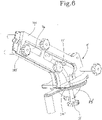
Figure 6 is an overall view of the invention shown in the previous figure, and -
Figure 7 shows a plurality of reinforcing elements, having different lengths, intended to be incorporated into the spacer realised by means of the invention. - With reference to the accompanying figures, reference number 1 and 1' indicate a forming mould of an orthopaedic spacer made of medical cement, in accordance with the present invention.
- The invention can also be used with known medical cements, which are however not described in detail in the following.
- In general terms, the mould 1, 1' defines a
moulding cavity 2 delimited by a mouldingsurface surface - The mould 1, 1' proposed comprises at least a
first sector first portion 8, 3' of themoulding surface 3 and at least asecond sector second portion surface - The first and the second surface portion have variable configurations, so as to be able to obtain spacers of variable sizes and shapes.
- To be precise, the first and the second surface portion are independently variable, according to methods explained below.
- According to a first embodiment illustrated in
figures 1 - 4 , the mould 1 comprises afirst moulding element 4a and asecond moulding element 4b. Thefirst moulding element 4a comprises afirst moulding surface 5a and thesecond element 4b comprises asecond moulding surface 5b. - In particular, the
first element 4a and thesecond element 4b are configured for being superposed on one another, at an open lateral surface which comprises thefirst surface 5a (in the case of thefirst element 4a) and thesecond surface 5b (in the case of thesecond element 4b). - In still greater detail, the two
moulding elements - The
first element 4a and thesecond element 4b together define a containing volume of the medical cement and further components able to form the spacer, which will be described in the following. - In the closed configuration of the mould 1, a
passage hole 6 is defined that is shaped by afirst channel 6a of thefirst element 4a and by asecond channel 6b of thesecond element 4b (see for examplefigure 1 ). - The
passage hole 6 enables inserting medical cement in liquid state into the mould 1. - The
first moulding element 4a and/or thesecond moulding element 4b are preferably made of polypropylene or of a polypropylene based material. - Since, in the preferred embodiment of the invention, the first and the
second element first element 4a, and what is described is also valid for thesecond element 4b, mutatis mutandis. Thefirst element 4a comprises afirst sector 7a and asecond sector 7b defining themoulding surface 3. - The
first sector 7a, defines at least afirst portion 8 of themoulding surface 3 and is for forming a first part of the orthopaedic spacer. - The mould preferably comprises a second forming insert 9 (illustrated in
figure 3 ) suitable for inserting in themoulding cavity 2 of the mould 1. - In particular, the second forming
insert 9 is insertable between thefirst portion 8 of thefirst moulding surface 5a of thefirst element 4a and thefirst portion 8 of thesecond moulding surface 5b of thesecond element 4b. For the sake of precision, the second forminginsert 9 has a complementary shape to ahead portion 8a of thefirst portion 8. - In greater detail, the second forming
insert 9 is configured for shaping the "head" of the spacer, i.e. the rounded part of the conformation destined to take the place of the missing epiphysis of the bone. - The second forming
insert 9 preferably comprises positioning means 10 configured for enabling the correct insertion of the forminginsert 9 in thefirst portion 8 of thefirst surface 5a (and/or thesecond surface 5b). - The positioning means 10 comprises at least a pair of
ribs 11 in relief on an external surface of the second forminginsert 9. In particular, theribs 11 are suitable for being operatively inserted into respective profiledportions 11a of thefirst moulding element 4a and/or thesecond moulding element 4b. In still greater detail, the second forminginsert 9 has a forming surface shaped as a concavespherical cap shape 11b, so as to be able to impress, on the bone cement, the form of the head of the spacer. - Preferably, the second forming insert is made of a TPE-SEBS based material; this is however not a unique solution.
- The
second sector 7b defines asecond portion 12 of thesurface 3 and is for forming a second part of the orthopaedic spacer, adjacent to the first part. - In particular, the
second sector 7b comprises ahousing 13 in which at least a half-part 14a (illustrated infigure 4 ) is insertable, of at least a first forminginsert 14 of the mould 1 (with reference to thesecond element 4b, reference will be made to the half-part 14b represented infigure 1 and complementary to the half-part 14a). - The half-
part 14a comprises thesecond portion 12 of thesurface 3 and has an elongate shape along a prevalent development direction configured for forming an elongate portion of the orthopaedic spacer in the superposed configuration of the first 4a and thesecond element 4b (and therefore in a superposed configuration of the half-part 14a and the half-part 14b, thus going to form the first forming insert 14). - The first forming
insert 14 is preferably configured for forming a portion of rod or "stalk" of the orthopaedic spacer, i.e. the part having an elongate shape which is destined to couple with the residual diaphysis of the bone. Thesecond portion 12 of thesurface 3 preferably has a tapered shape along the development direction in a distancing direction from thefirst portion 8. - Further, the
second portion 12 of thesurface 3 has a cone shape. - The mould 1 preferably comprises a plurality of first forming
inserts 14 that are inter-replaceable, on the basis of the dimension of the spacer that is to be obtained. - In particular, each first forming
insert 14 has a different width and/or length of thesecond portion 12, i.e. of the concave part, so as to realise orthopaedic spacers having different dimensions. - In practice, on the basis of the physical characteristics of the patient, spacers can be obtained having different transversal and/or longitudinal dimensions.
- In the embodiment of
figure 4 , thesecond portion 12 of thesurface 3 has therod portion 12a and aconduit 12b configured for enabling insertion and distribution of the medical cement. - The first forming
insert 14 is preferably made of a TPE-SEBS based material; this is however not a unique solution, as the first insert could also be made of polypropylene or another material besides. - As concerns the transversal dimensions of the spacer, the invention provides a good degree of modularity, as by replacing the
first insert 14, spacers of different thickness can be obtained. - As concerns the longitudinal dimension, the invention enables a continuous modularity, as the length of the stalk or rod of the spacer is a direction function of the quantity of bone cement poured into the mould during the forming operations.
- In fact, during the filling of the mould 1 with bone cement, the mould 1 is positioned so as to have the
first portion 8 thereof inferiorly located with respect to thesecond portion 12, so that thepassage hole 6 enables easy insertion of a portion of bone cement. - In this way it is possible to regulate, with absolute precision, the longitudinal dimensions of the
second portion 12 on the basis of the volume of cement inserted through thehole 6. - The mould further comprises a reinforcing
element 15 or "internal core", possibly of known type, insertable in the two forming inserts. - The reinforcing
element 15 is preferably made of steel and is constituted by a profiledplate 15a, defined by afirst portion 15b and asecond portion 15c that are angled with respect to one another. - In this way, during the filling step of the mould 1 with the bone cement, the reinforcing
element 15 is sunken into the cement, with thefirst portion 15b remaining sunken in the head of the spacer, while thesecond portion 15b is incorporated in the stalk. - The mould 1 comprises coupling means 17 configured for joining the
first element 4a and thesecond element 4b in a superposed configuration of thefirst element 4a with thesecond element 4b. The coupling means 17 is conformed so as to join thefirst element 4a and thesecond element 4b by locking and/or jointing in order to position them correctly one on the other. Once loaded with the medical cement (in the quantity necessary for obtaining the desired longitudinal dimensions), the mould 1 is pressed by a press of known type that is therefore not a part of the present description. Once the cement has hardened, it defines the spacer with can therefore be removed from the mould and inserted in the patient's body. - The present invention relates to a method for forming an orthopaedic spacer.
- The method, in a first version thereof, envisages providing a mould 1 realised in accordance with the first embodiment described above.
- Therefore the first forming
insert 14 and the second forminginsert 9 are selected on the basis of the characteristics of the patient's physique, i.e. on the basis of the dimensions of the portions of bone on which the spacer intervenes. - A reinforcing
element 15 is also predisposed, to be located internally of the two forming inserts, the dimensions of whichelement 15 are also a function of the physical characteristics of the patient. - At this point, the mould 1 is positioned so that the
head portion 8a is located inferiorly of therod portion 12a and the mould 1 is filled with bone cement, sliding the bone cement through thepassage hole 6. - The quantity of cement inserted defines the longitudinal dimensions of the spacer.
- The pressing step of the mould 1 then follows, and the consequent solidifying step of the bone cement, so as to obtain the desired spacer. The mould 1 and the method described in the foregoing are able to obviate the drawbacks that have emerged in the prior art.
- The above-mentioned mould 1 advantageously enables obtaining an orthopaedic spacer that is specific for a specific patient by modelling the
head portion 8a by means of a second forminginsert 9 and regulating the longitudinal and transversal dimensions of therod portion 12a by means of the first forminginsert 14. - Still more advantageously, the first forming
insert 14 enables both obtaining a plurality of transversal dimensions that are different from the rod or "stalk" of the spacer, simply by replacing the first forminginsert 14 with another forminginsert 14, and obtaining any longitudinal dimension of the rod portion, in the above-explained ways. - In accordance with a second embodiment of the invention, illustrated in
figures 5 and6 , the mould 1' includes a plurality offirst sectors 7a', 7a" andsecond sectors 7b' replaceable and differently combinable. - The
first sectors 7a', 7a" are intended for the forming of parts of stalk of the spacer and are equipped with respective surface portions 3' having different configurations, in particular dimensions, thus defining different stalk parts. - Also, in this case, as in the first embodiment, the first surface portion 3' is counter-shaped to the shape of the stalk, which assumes the conformation already explained previously.
- Furthermore, the invention envisages a plurality of
second sectors 7b', intended for the forming of head parts of the spacer and equipped with respectivesecond surface portions 3", having different configurations, thus defining different head parts, especially with respect to the dimensions. - In practice, based on the stalk and head dimensions to be obtained, the user uses a different
first sector 7a', 7a" and a differentsecond sector 7b' on a case-by-case basis, so as to be able to realise a spacer that adapts, in terms of size and possibly shape, to the different needs of the specific patient. - Preferably, each first sector comprises a first and a
second moulding element 7a', 7a", removably joinable, to define a partial formingcavity 30 for a spacer stalk, delimited by thefirst surface portion 3', 3". - As shown in
figures 5 and6 the twomoulding elements 7a', 7a" together form a blister structure and are adapted to be overlapped with each other, at a contact surface. - In still greater detail, the two
moulding elements 7a', 7a" can be specular and therefore symmetrical with respect to a join plane, at which they contact to define a part of the closed mould 1'. - In the example represented, where the blister structure is shown, each
moulding element 7a', 7a" conforms aperipheral flange 70', 70", which defines the mentioned contact surface and is adapted to the abutment with theflange 70', 70" of the other element. - Centrally to the
flange 70', 70", the internal forming surface 3' is conformed, like a "footprint" of the stalk, i.e. comprising a concavity intended to face the concavity of the other moulding element 1'. - As can be seen in
figure 5 , such concavity may have a first substantially cylindrical part, possibly tapered towards an end, as already mentioned in relation to the first embodiment of the invention, which defines the stalk in the strict sense, while it has a fold in an elbow-like way towards the opposite end, so as to define the junction part between the stalk and head of the spacer. - The
first element 4a and thesecond element 4b together define a containing volume of the medical cement and of theinternal core 15 already mentioned above. - Each second sector includes a respective
third moulding element 7b', comprising a formingconcavity 300 that defines at least partially thesecond surface portion 3" and is intended for the forming of a spacer head. Preferably, the third moulding element is asemi-spherical cap 7b', provided with anannular flange 71 at the mouth to theconcavity 300. - In this case, at an end thereof, the
first sector 7a', 7a" comprises aflange 71', 71" transversal to its longitudinal extension, which surrounds the internal formingcavity 30 of the stalk and is intended for contact with theannular flange 71 of thecap 7b in order to define a complete mould 1' for the spacer. - In even more detail, the first and the
second moulding element 7a', 7a" of the forming blister of the stalk, each include their own half-flange 71', 71", so that, once joined, the complete flange of the first sector is obtained. - Therefore, the mould 1' has an open configuration (shown in
figure 5 ), in which it is formed by threeparts 7a', 7a", 7b', two specular moulding elements for the stalk, which together constitute the mentioned blister and then a third moulding element that is applied at one end of the blister. - In the closed configuration of the mould (shown in
figure 6 ), a unitary internal cavity is obtained which is defined by theconcave surfaces 3', 3‴ of the three moulding elements and is counter-shaped to the shape of the spacer to be obtained. - In the closed configuration of the mould 1, a passage hole 6' is defined that is formed by a
first channel 6a' of thefirst element 7a' and by asecond channel 6a" of thesecond element 7a". - The passage hole 6' enables inserting medical cement in liquid state into the mould 1'.
- The advantage of the invention, also in this embodiment, is that the dimensions (and possibly also the shape) of the spacer are variable, since by choosing a
different blister 7a', 7a" a different stalk can be obtained, for example with a different thickness; in the same way, by choosing adifferent cap 7b' a head with a different diameter is obtained. - By combining
different blisters 7a', 7a" anddifferent caps 7b' complete modularity can be obtained, which allows a multitude of spacers to be obtained realised according to the requirements of the specific patient. - It is to be noted that the invention may also envisage providing a plurality of
internal cores 15 of different sizes, in particular lengths. - In even more detail, as shown in
figure 7 , the length modularity of the reinforcing elements may be obtained through the application of extensions 15', comprising linear members of different lengths, that can be coupled to the core 15 so as to vary its total longitudinal dimensions. - Therefore, the invention also allows a modularity to be obtained of the reinforcing elements intended to be incorporated into the stalk of the spacer. In this way, according to the specific patient, a core 15 can be chosen that is adapted to confer the right resistance to the stalk of the spacer; a greater length allows increased resistance along the longitudinal extension of the spacer.
- The
blister 7a', 7a" and thecap 7b' are preferably made of polypropylene or of a polypropylene based material. - For the purpose of realising the spacer, the invention envisages the use of a press that is used to give the mould 1' sufficient pressure for the correct forming of the spacer.
- The proposed press includes three
main components - In detail, two
lateral structures 100, 100' are provided, substantially specular, adapted to close theblister 7a', 7a" in a sandwich-like way on opposite sides, so as to compress it in an adjustable way. - For that purpose, adjusting screws generally indicated by 11' are provided, which allow the user to adjust the pressure that the two
structures 100, 100' exert on opposite sides on the blister. - The
lateral structures 100, 100', have a generally planar shape, with an outline alike to that of the first elements of theblister 7a', 7a", and may provide housing passages of the aforementioned footprints of the stalk, i.e. external convexities that, entirely, have the first surface portion 3' that is used to form the stalk of the spacer. - Furthermore, the press comprises a
head structure 100", adapted to compress thehead cap 7b', which may include a ring which internally receives the convexity of thecap 7b', which ring presses against the mentionedflange 71 of thecap 7b' which abuts with theflange 71', 71" of theblister 7a', 7a", which in turn abuts with aflange 72', 72" formed by thelateral structures 100, 100' of the press. - In detail, each
lateral structure 100, 100' conforms its own half-flange 72', 72" in a way not dissimilar to theblister 7a', 7a". - The
head structure 100" of the press is also equipped with adjusting screws, indicated by 12', which are used to adjust the pressure. - The process for realising the spacer through the use of the mould 1', realised in accordance with the second embodiment of the invention, envisages the following steps:
- choosing a
first sector 7a', 7a" according to conformational and/or dimensional aspects of the stalk of the spacer to be formed; - choosing a
second sector 7b' according to conformational and/or dimensional aspects of the head of the spacer to be formed; - choosing an
internal core 15 according to the dimensions of the stalk to be formed; - inserting the core 15 in the
cavity 30 of thefirst sector 7a', 7a"; - joining the first and the second sector, so as to form the mould 1';
- inserting bone cement into the mould 1';
- pressing said mould 1', preferably with the
press - once the bone cement has hardened, extracting the spacer formed from the mould 1'.
Claims (2)
- A system (1', 100, 100', 100") including a modular mould (1') for forming an orthopaedic spacer, shaping a head and a stalk and made of medical cement, defining a moulding cavity (2) delimited by a moulding surface (3', 3") configured for impressing a predetermined shape on said medical cement and for realising said orthopaedic spacer, said mould ( 1') comprising a plurality of sectors ( 7a', 7a"), each defining at least a first portion of said surface , and least a second sectors (7b') defining at least a second portion of said surface, said first and second portion of the surface being variable, so as to obtain spacers of variable dimensions;wherein the first and the second portion of surface (3', 3") are variable independently from each other;wherein the mould (1') further comprises a reinforcing element (15);wherein the first sectors (7a', 7a") are intended for the forming of parts of stalk of the spacer and are equipped with respective surface portions (3') having different configurations, in particular dimensions, thus defining different stalk parts;wherein the first surface portion (3') is counter-shaped to the shape of the stalk;wherein a plurality of second sectors (7b') are provided, intended for the forming of head parts of the spacer and equipped with respective second surface portions (3"), having different configurations, thus defining different head parts;wherein each first sector comprises a first and a second moulding element (7a', 7a"), removably joinable, to define a partial forming cavity (30) for a spacer stalk, delimited by the first surface portion (3', 3");characterized in that the two moulding elements (7a', 7a") together form a blister structure and are adapted to be overlapped with each other, at a contact surface;wherein each moulding element (7a', 7a") conforms a peripheral flange (70', 70"), which defines the mentioned contact surface and is adapted to the abutment with the flange (70', 70") of the other element;wherein centrally to the flange (70', 70"), the internal forming surface (3') is conformed, comprising a concavity intended to face the concavity of the other moulding element (1');wherein the first element (4a) and the second element (4b) together define a containing volume of the medical cement and of said reinforcing element (15);wherein each second sector includes a respective third moulding element (7b'), comprising a forming concavity (300) that defines at least partially the second surface portion (3") and is intended for the forming of the spacer head;wherein the third moulding element is a semi-spherical cap (7b'), provided with an annular flange (71) at the mouth to the concavity (300);wherein, at an end thereof, the first sector (7a', 7a") comprises a flange (71', 71") transversal to its longitudinal extension, which surrounds the internal forming cavity (30) of the stalk and is intended for contact with the annular flange (71) of the cap (7b) in order to define a complete mould (1') for the spacer;wherein, the first and the second moulding element (7a', 7a") of the forming blister of the stalk, each include their own half-flange (71', 71"), so that, once joined, the complete flange of the first sector is obtained;wherein a press is provided in said system (1', 100, 100', 100"), which includes three main components (100, 100', 100"), intended to close and compress the mould (1'), comprising two lateral structures (100, 100'), substantially specular, adapted to close said blister (7a', 7a") in a sandwich-like way on opposite sides, so as to compress it in an adjustable way; and wherein adjusting screws (11') are provided, which allow the user to adjust the pressure that the two structures (100, 100') exert on opposite sides on the blister.
- A method for forming an orthopaedic spacer, through the use of a mould (1') according to claim 1, comprising the following steps:- providing a mould (1') according to claim 1;- choosing a first sector (7a', 7a") according to conformational and/or dimensional aspects of the stalk of the spacer to be formed;- choosing a sector (7b') according to conformational and/or dimensional aspects of the head of the spacer to be formed;- choosing an internal core (15) according to the dimensions of the stalk to be formed;- inserting the core (15) into the cavity (30) of the first sector (7a', 7a");- joining the first and the second sector, so as to form the mould (1');- inserting bone cement into the mould (1');- pressing said mould (1'); and- once the bone cement has hardened, extracting the spacer formed from the mould (1').
Priority Applications (3)
| Application Number | Priority Date | Filing Date | Title |
|---|---|---|---|
| HRP20230141TT HRP20230141T1 (en) | 2017-05-04 | 2018-01-22 | A mould and a method for forming an orthopaedic spacer made of medical cement |
| SI201830847T SI3618772T1 (en) | 2017-05-04 | 2018-01-22 | A mould and a method for forming an orthopaedic spacer made of medical cement |
| RS20230116A RS63979B1 (en) | 2017-05-04 | 2018-01-22 | MOLD AND PROCEDURE FOR FORMING ORTHOPEDIC SPACER MADE OF MEDICAL CEMENT |
Applications Claiming Priority (2)
| Application Number | Priority Date | Filing Date | Title |
|---|---|---|---|
| IT102017000048295A IT201700048295A1 (en) | 2017-05-04 | 2017-05-04 | Mold and method for forming an orthopedic spacer in medical cement. |
| PCT/IB2018/050375 WO2018203150A1 (en) | 2017-05-04 | 2018-01-22 | A mould and a method for forming an orthopaedic spacer made of medical cement |
Publications (2)
| Publication Number | Publication Date |
|---|---|
| EP3618772A1 EP3618772A1 (en) | 2020-03-11 |
| EP3618772B1 true EP3618772B1 (en) | 2022-12-21 |
Family
ID=60766025
Family Applications (1)
| Application Number | Title | Priority Date | Filing Date |
|---|---|---|---|
| EP18705020.8A Active EP3618772B1 (en) | 2017-05-04 | 2018-01-22 | A mould and a method for forming an orthopaedic spacer made of medical cement |
Country Status (16)
| Country | Link |
|---|---|
| US (2) | US20180319057A1 (en) |
| EP (1) | EP3618772B1 (en) |
| AU (1) | AU2018262340B2 (en) |
| BR (1) | BR112019023086B1 (en) |
| DK (1) | DK3618772T3 (en) |
| ES (1) | ES2938481T3 (en) |
| FI (1) | FI3618772T3 (en) |
| HR (1) | HRP20230141T1 (en) |
| HU (1) | HUE061131T2 (en) |
| IT (1) | IT201700048295A1 (en) |
| LT (1) | LT3618772T (en) |
| PL (1) | PL3618772T3 (en) |
| PT (1) | PT3618772T (en) |
| RS (1) | RS63979B1 (en) |
| SI (1) | SI3618772T1 (en) |
| WO (1) | WO2018203150A1 (en) |
Cited By (1)
| Publication number | Priority date | Publication date | Assignee | Title |
|---|---|---|---|---|
| US12128592B2 (en) | 2017-05-04 | 2024-10-29 | G21 S.R.L. | Mould and a method for forming an orthopaedic spacer made of medical cement |
Families Citing this family (5)
| Publication number | Priority date | Publication date | Assignee | Title |
|---|---|---|---|---|
| CN107190604B (en) * | 2017-05-24 | 2019-11-05 | 中建钢构有限公司 | A kind of bicycle expressway girder steel paving structure and its paving method |
| JP7090186B2 (en) | 2020-03-20 | 2022-06-23 | ヘレウス メディカル ゲーエムベーハー | Equipment and methods for manufacturing spacers |
| EP3900680B1 (en) * | 2020-04-24 | 2022-06-29 | Heraeus Medical GmbH | Device and method for producing spacers with variable head |
| EP3939546B1 (en) * | 2020-07-17 | 2023-10-11 | Heraeus Medical GmbH | Device and method for producing spacers |
| IT202100009899A1 (en) * | 2021-04-19 | 2022-10-19 | Cossington Ltd | MOLD WITH REMOVABLE INSERTS FOR THE FORMING OF A SPACER DEVICE FOR THE REPLACEMENT OF A JOINT PROSTHESIS |
Citations (18)
| Publication number | Priority date | Publication date | Assignee | Title |
|---|---|---|---|---|
| US20020025358A1 (en) | 1996-03-11 | 2002-02-28 | Carl Nelson | Composite allograft press |
| US6361731B1 (en) | 1998-07-15 | 2002-03-26 | Biomet, Inc. | Method of forming a temporary implant |
| US20070063378A1 (en) | 2005-09-16 | 2007-03-22 | O'donoghue Joseph | Compound tooling system for molding applications |
| US20070222114A1 (en) | 2006-03-23 | 2007-09-27 | Ziran Bruce H | Method of forming a temporary implant and mold assembly for same |
| US20080015692A1 (en) | 2006-07-12 | 2008-01-17 | Eric S Heinz | Vertebral implant including preformed osteoconductive insert and methods of forming |
| US20090157189A1 (en) | 2007-12-13 | 2009-06-18 | Biomet Manufacturing Corp. | Modular Articulating Cement Spacer Mold |
| US20100102484A1 (en) | 2008-10-29 | 2010-04-29 | Sean Haney | Spacer molds with releasable securement |
| US20120256344A1 (en) | 2011-04-06 | 2012-10-11 | Stolarski Edward | Disposable orthopedic prosthesis mold |
| WO2013086177A1 (en) | 2011-12-06 | 2013-06-13 | Holt Christopher J | Spacer mold for orthopedic implants |
| US20130344186A1 (en) | 2007-12-07 | 2013-12-26 | Zimmer Orthopaedic Surgical Products, Inc. | Spacer mold and methods therefor |
| WO2014072076A1 (en) | 2012-11-12 | 2014-05-15 | Université Du Luxembourg | Temporary prosthesis head |
| US8920152B2 (en) | 2007-12-13 | 2014-12-30 | Biomet Manufacturing, Llc | Modular articulating cement spacer |
| EP2522310B1 (en) | 2011-05-10 | 2016-04-13 | Heraeus Medical GmbH | Mould for producing spacers for endoprosthetics |
| WO2016071939A1 (en) | 2014-11-06 | 2016-05-12 | Cappelletti Ava | Mould for forming of a joint spacer device or a part thereof |
| US20160332328A1 (en) | 2015-03-27 | 2016-11-17 | Heraeus Medical Gmbh | Spacer mould and method for producing hip spacers |
| WO2017125832A1 (en) | 2016-01-19 | 2017-07-27 | G21 S.R.L. | Mould for realizing a temporary prosthesis of hip or shoulder, and method thereof |
| EP3245981A1 (en) | 2016-05-17 | 2017-11-22 | G21 S.r.l. | Mould and accessories thereof destined for the forming of an orthopedic modular spacer |
| IT201700048295A1 (en) | 2017-05-04 | 2018-11-04 | G21 S R L | Mold and method for forming an orthopedic spacer in medical cement. |
-
2017
- 2017-05-04 IT IT102017000048295A patent/IT201700048295A1/en unknown
- 2017-05-30 US US15/608,304 patent/US20180319057A1/en not_active Abandoned
-
2018
- 2018-01-22 EP EP18705020.8A patent/EP3618772B1/en active Active
- 2018-01-22 PT PT187050208T patent/PT3618772T/en unknown
- 2018-01-22 WO PCT/IB2018/050375 patent/WO2018203150A1/en not_active Ceased
- 2018-01-22 SI SI201830847T patent/SI3618772T1/en unknown
- 2018-01-22 AU AU2018262340A patent/AU2018262340B2/en active Active
- 2018-01-22 LT LTEPPCT/IB2018/050375T patent/LT3618772T/en unknown
- 2018-01-22 FI FIEP18705020.8T patent/FI3618772T3/en active
- 2018-01-22 BR BR112019023086-6A patent/BR112019023086B1/en active IP Right Grant
- 2018-01-22 DK DK18705020.8T patent/DK3618772T3/en active
- 2018-01-22 PL PL18705020.8T patent/PL3618772T3/en unknown
- 2018-01-22 HU HUE18705020A patent/HUE061131T2/en unknown
- 2018-01-22 RS RS20230116A patent/RS63979B1/en unknown
- 2018-01-22 HR HRP20230141TT patent/HRP20230141T1/en unknown
- 2018-01-22 US US16/759,207 patent/US12128592B2/en active Active
- 2018-01-22 ES ES18705020T patent/ES2938481T3/en active Active
Patent Citations (19)
| Publication number | Priority date | Publication date | Assignee | Title |
|---|---|---|---|---|
| US20020025358A1 (en) | 1996-03-11 | 2002-02-28 | Carl Nelson | Composite allograft press |
| US6361731B1 (en) | 1998-07-15 | 2002-03-26 | Biomet, Inc. | Method of forming a temporary implant |
| US20070063378A1 (en) | 2005-09-16 | 2007-03-22 | O'donoghue Joseph | Compound tooling system for molding applications |
| US20070222114A1 (en) | 2006-03-23 | 2007-09-27 | Ziran Bruce H | Method of forming a temporary implant and mold assembly for same |
| US20080015692A1 (en) | 2006-07-12 | 2008-01-17 | Eric S Heinz | Vertebral implant including preformed osteoconductive insert and methods of forming |
| US20130344186A1 (en) | 2007-12-07 | 2013-12-26 | Zimmer Orthopaedic Surgical Products, Inc. | Spacer mold and methods therefor |
| US8920152B2 (en) | 2007-12-13 | 2014-12-30 | Biomet Manufacturing, Llc | Modular articulating cement spacer |
| US20090157189A1 (en) | 2007-12-13 | 2009-06-18 | Biomet Manufacturing Corp. | Modular Articulating Cement Spacer Mold |
| US20100102484A1 (en) | 2008-10-29 | 2010-04-29 | Sean Haney | Spacer molds with releasable securement |
| US20120256344A1 (en) | 2011-04-06 | 2012-10-11 | Stolarski Edward | Disposable orthopedic prosthesis mold |
| EP2522310B1 (en) | 2011-05-10 | 2016-04-13 | Heraeus Medical GmbH | Mould for producing spacers for endoprosthetics |
| WO2013086177A1 (en) | 2011-12-06 | 2013-06-13 | Holt Christopher J | Spacer mold for orthopedic implants |
| WO2014072076A1 (en) | 2012-11-12 | 2014-05-15 | Université Du Luxembourg | Temporary prosthesis head |
| WO2016071939A1 (en) | 2014-11-06 | 2016-05-12 | Cappelletti Ava | Mould for forming of a joint spacer device or a part thereof |
| US20160332328A1 (en) | 2015-03-27 | 2016-11-17 | Heraeus Medical Gmbh | Spacer mould and method for producing hip spacers |
| WO2017125832A1 (en) | 2016-01-19 | 2017-07-27 | G21 S.R.L. | Mould for realizing a temporary prosthesis of hip or shoulder, and method thereof |
| EP3245981A1 (en) | 2016-05-17 | 2017-11-22 | G21 S.r.l. | Mould and accessories thereof destined for the forming of an orthopedic modular spacer |
| IT201700048295A1 (en) | 2017-05-04 | 2018-11-04 | G21 S R L | Mold and method for forming an orthopedic spacer in medical cement. |
| WO2018203150A1 (en) | 2017-05-04 | 2018-11-08 | G21 S.R.L. | A mould and a method for forming an orthopaedic spacer made of medical cement |
Non-Patent Citations (1)
| Title |
|---|
| ANONYMOUS: "StageOne™ Select Hip Cement Spacer Molds", ZIMMER BIOMET, 1 January 2016 (2016-01-01), pages 1 - 16, XP093131847 |
Cited By (1)
| Publication number | Priority date | Publication date | Assignee | Title |
|---|---|---|---|---|
| US12128592B2 (en) | 2017-05-04 | 2024-10-29 | G21 S.R.L. | Mould and a method for forming an orthopaedic spacer made of medical cement |
Also Published As
| Publication number | Publication date |
|---|---|
| SI3618772T1 (en) | 2023-04-28 |
| LT3618772T (en) | 2023-03-10 |
| DK3618772T3 (en) | 2023-02-06 |
| WO2018203150A1 (en) | 2018-11-08 |
| AU2018262340B2 (en) | 2023-11-16 |
| RS63979B1 (en) | 2023-03-31 |
| US20180319057A1 (en) | 2018-11-08 |
| US12128592B2 (en) | 2024-10-29 |
| ES2938481T3 (en) | 2023-04-11 |
| AU2018262340A1 (en) | 2019-10-31 |
| US20200316824A1 (en) | 2020-10-08 |
| PL3618772T3 (en) | 2023-03-20 |
| EP3618772A1 (en) | 2020-03-11 |
| BR112019023086A2 (en) | 2020-05-26 |
| HUE061131T2 (en) | 2023-05-28 |
| FI3618772T3 (en) | 2023-03-22 |
| HRP20230141T1 (en) | 2023-03-31 |
| IT201700048295A1 (en) | 2018-11-04 |
| PT3618772T (en) | 2023-02-13 |
| BR112019023086B1 (en) | 2023-12-12 |
Similar Documents
| Publication | Publication Date | Title |
|---|---|---|
| US12128592B2 (en) | Mould and a method for forming an orthopaedic spacer made of medical cement | |
| CN105997308B (en) | For producing the sept mould and method of hip sept | |
| EP2288312B1 (en) | Spacer molds and methods therefor | |
| US9993340B2 (en) | Mould and accessories thereof destined for the forming of an orthopedic modular spacer | |
| AU2003200571B2 (en) | Method of making an orthopaedic implant having a porous metal surface | |
| US5124106A (en) | Method of making a femoral rasp | |
| EP3405142B1 (en) | Mould for realizing a temporary prosthesis of hip or shoulder, and method thereof | |
| US20250331991A1 (en) | Adjustable mold for forming spacer devices or parts thereof | |
| EP3632381B1 (en) | Mould for making a temporary prosthetic component for a knee | |
| US20070179630A1 (en) | Hip stem centralizer cap and method | |
| CN209884430U (en) | Mold assembly for manufacturing hip joint spacer | |
| HK1061345B (en) | Method of making an orthopaedic implant having a porous metal surface |
Legal Events
| Date | Code | Title | Description |
|---|---|---|---|
| REG | Reference to a national code |
Ref country code: HR Ref legal event code: TUEP Ref document number: P20230141T Country of ref document: HR |
|
| STAA | Information on the status of an ep patent application or granted ep patent |
Free format text: STATUS: UNKNOWN |
|
| STAA | Information on the status of an ep patent application or granted ep patent |
Free format text: STATUS: THE INTERNATIONAL PUBLICATION HAS BEEN MADE |
|
| PUAI | Public reference made under article 153(3) epc to a published international application that has entered the european phase |
Free format text: ORIGINAL CODE: 0009012 |
|
| STAA | Information on the status of an ep patent application or granted ep patent |
Free format text: STATUS: REQUEST FOR EXAMINATION WAS MADE |
|
| 17P | Request for examination filed |
Effective date: 20191018 |
|
| AK | Designated contracting states |
Kind code of ref document: A1 Designated state(s): AL AT BE BG CH CY CZ DE DK EE ES FI FR GB GR HR HU IE IS IT LI LT LU LV MC MK MT NL NO PL PT RO RS SE SI SK SM TR |
|
| AX | Request for extension of the european patent |
Extension state: BA ME |
|
| DAV | Request for validation of the european patent (deleted) | ||
| DAX | Request for extension of the european patent (deleted) | ||
| STAA | Information on the status of an ep patent application or granted ep patent |
Free format text: STATUS: EXAMINATION IS IN PROGRESS |
|
| 17Q | First examination report despatched |
Effective date: 20201217 |
|
| GRAP | Despatch of communication of intention to grant a patent |
Free format text: ORIGINAL CODE: EPIDOSNIGR1 |
|
| STAA | Information on the status of an ep patent application or granted ep patent |
Free format text: STATUS: GRANT OF PATENT IS INTENDED |
|
| INTG | Intention to grant announced |
Effective date: 20220909 |
|
| GRAS | Grant fee paid |
Free format text: ORIGINAL CODE: EPIDOSNIGR3 |
|
| GRAJ | Information related to disapproval of communication of intention to grant by the applicant or resumption of examination proceedings by the epo deleted |
Free format text: ORIGINAL CODE: EPIDOSDIGR1 |
|
| GRAL | Information related to payment of fee for publishing/printing deleted |
Free format text: ORIGINAL CODE: EPIDOSDIGR3 |
|
| GRAA | (expected) grant |
Free format text: ORIGINAL CODE: 0009210 |
|
| STAA | Information on the status of an ep patent application or granted ep patent |
Free format text: STATUS: THE PATENT HAS BEEN GRANTED |
|
| AK | Designated contracting states |
Kind code of ref document: B1 Designated state(s): AL AT BE BG CH CY CZ DE DK EE ES FI FR GB GR HR HU IE IS IT LI LT LU LV MC MK MT NL NO PL PT RO RS SE SI SK SM TR |
|
| INTG | Intention to grant announced |
Effective date: 20220909 |
|
| REG | Reference to a national code |
Ref country code: GB Ref legal event code: FG4D |
|
| REG | Reference to a national code |
Ref country code: DE Ref legal event code: R096 Ref document number: 602018044451 Country of ref document: DE |
|
| REG | Reference to a national code |
Ref country code: CH Ref legal event code: EP |
|
| REG | Reference to a national code |
Ref country code: AT Ref legal event code: REF Ref document number: 1538604 Country of ref document: AT Kind code of ref document: T Effective date: 20230115 |
|
| REG | Reference to a national code |
Ref country code: IE Ref legal event code: FG4D |
|
| REG | Reference to a national code |
Ref country code: DK Ref legal event code: T3 Effective date: 20230201 |
|
| REG | Reference to a national code |
Ref country code: RO Ref legal event code: EPE Ref country code: PT Ref legal event code: SC4A Ref document number: 3618772 Country of ref document: PT Date of ref document: 20230213 Kind code of ref document: T Free format text: AVAILABILITY OF NATIONAL TRANSLATION Effective date: 20230207 |
|
| REG | Reference to a national code |
Ref country code: NL Ref legal event code: FP |
|
| REG | Reference to a national code |
Ref country code: SE Ref legal event code: TRGR |
|
| REG | Reference to a national code |
Ref country code: EE Ref legal event code: FG4A Ref document number: E023004 Country of ref document: EE Effective date: 20230206 |
|
| REG | Reference to a national code |
Ref country code: GR Ref legal event code: EP Ref document number: 20230400248 Country of ref document: GR Effective date: 20230307 |
|
| REG | Reference to a national code |
Ref country code: NO Ref legal event code: T2 Effective date: 20221221 |
|
| REG | Reference to a national code |
Ref country code: HR Ref legal event code: T1PR Ref document number: P20230141 Country of ref document: HR |
|
| REG | Reference to a national code |
Ref country code: ES Ref legal event code: FG2A Ref document number: 2938481 Country of ref document: ES Kind code of ref document: T3 Effective date: 20230411 |
|
| REG | Reference to a national code |
Ref country code: SK Ref legal event code: T3 Ref document number: E 41295 Country of ref document: SK |
|
| REG | Reference to a national code |
Ref country code: HU Ref legal event code: AG4A Ref document number: E061131 Country of ref document: HU |
|
| P01 | Opt-out of the competence of the unified patent court (upc) registered |
Effective date: 20230523 |
|
| PG25 | Lapsed in a contracting state [announced via postgrant information from national office to epo] |
Ref country code: SM Free format text: LAPSE BECAUSE OF FAILURE TO SUBMIT A TRANSLATION OF THE DESCRIPTION OR TO PAY THE FEE WITHIN THE PRESCRIBED TIME-LIMIT Effective date: 20221221 |
|
| REG | Reference to a national code |
Ref country code: HR Ref legal event code: PBON Ref document number: P20230141 Country of ref document: HR Effective date: 20230122 |
|
| REG | Reference to a national code |
Ref country code: LT Ref legal event code: MM4D Effective date: 20230122 |
|
| REG | Reference to a national code |
Ref country code: EE Ref legal event code: MM4A Ref document number: E023004 Country of ref document: EE Effective date: 20230131 |
|
| PG25 | Lapsed in a contracting state [announced via postgrant information from national office to epo] |
Ref country code: AL Free format text: LAPSE BECAUSE OF FAILURE TO SUBMIT A TRANSLATION OF THE DESCRIPTION OR TO PAY THE FEE WITHIN THE PRESCRIBED TIME-LIMIT Effective date: 20221221 |
|
| REG | Reference to a national code |
Ref country code: DE Ref legal event code: R026 Ref document number: 602018044451 Country of ref document: DE |
|
| PLBI | Opposition filed |
Free format text: ORIGINAL CODE: 0009260 |
|
| PG25 | Lapsed in a contracting state [announced via postgrant information from national office to epo] |
Ref country code: MC Free format text: LAPSE BECAUSE OF FAILURE TO SUBMIT A TRANSLATION OF THE DESCRIPTION OR TO PAY THE FEE WITHIN THE PRESCRIBED TIME-LIMIT Effective date: 20221221 Ref country code: LU Free format text: LAPSE BECAUSE OF NON-PAYMENT OF DUE FEES Effective date: 20230122 |
|
| PLAX | Notice of opposition and request to file observation + time limit sent |
Free format text: ORIGINAL CODE: EPIDOSNOBS2 |
|
| 26 | Opposition filed |
Opponent name: WACH, MARCEL Effective date: 20230920 |
|
| PG25 | Lapsed in a contracting state [announced via postgrant information from national office to epo] |
Ref country code: FI Free format text: LAPSE BECAUSE OF NON-PAYMENT OF DUE FEES Effective date: 20230122 Ref country code: EE Free format text: LAPSE BECAUSE OF NON-PAYMENT OF DUE FEES Effective date: 20230131 Ref country code: CZ Free format text: LAPSE BECAUSE OF NON-PAYMENT OF DUE FEES Effective date: 20230122 Ref country code: CY Free format text: LAPSE BECAUSE OF NON-PAYMENT OF DUE FEES Effective date: 20230122 |
|
| PG25 | Lapsed in a contracting state [announced via postgrant information from national office to epo] |
Ref country code: LV Free format text: LAPSE BECAUSE OF NON-PAYMENT OF DUE FEES Effective date: 20230122 Ref country code: LT Free format text: LAPSE BECAUSE OF NON-PAYMENT OF DUE FEES Effective date: 20230122 Ref country code: HU Free format text: LAPSE BECAUSE OF NON-PAYMENT OF DUE FEES Effective date: 20230123 Ref country code: HR Free format text: LAPSE BECAUSE OF NON-PAYMENT OF DUE FEES Effective date: 20230122 Ref country code: GR Free format text: LAPSE BECAUSE OF NON-PAYMENT OF DUE FEES Effective date: 20230804 |
|
| REG | Reference to a national code |
Ref country code: AT Ref legal event code: UEP Ref document number: 1538604 Country of ref document: AT Kind code of ref document: T Effective date: 20221221 |
|
| PLBB | Reply of patent proprietor to notice(s) of opposition received |
Free format text: ORIGINAL CODE: EPIDOSNOBS3 |
|
| PG25 | Lapsed in a contracting state [announced via postgrant information from national office to epo] |
Ref country code: AL Free format text: LAPSE BECAUSE OF FAILURE TO SUBMIT A TRANSLATION OF THE DESCRIPTION OR TO PAY THE FEE WITHIN THE PRESCRIBED TIME-LIMIT Effective date: 20221221 |
|
| PGRI | Patent reinstated in contracting state [announced from national office to epo] |
Ref country code: AL Effective date: 20230213 |
|
| PLAB | Opposition data, opponent's data or that of the opponent's representative modified |
Free format text: ORIGINAL CODE: 0009299OPPO |
|
| PG25 | Lapsed in a contracting state [announced via postgrant information from national office to epo] |
Ref country code: BG Free format text: LAPSE BECAUSE OF NON-PAYMENT OF DUE FEES Effective date: 20230122 |
|
| R26 | Opposition filed (corrected) |
Opponent name: WACH, MARCEL Effective date: 20230920 |
|
| PG25 | Lapsed in a contracting state [announced via postgrant information from national office to epo] |
Ref country code: BG Free format text: LAPSE BECAUSE OF NON-PAYMENT OF DUE FEES Effective date: 20230122 |
|
| APBP | Date of receipt of notice of appeal recorded |
Free format text: ORIGINAL CODE: EPIDOSNNOA2O |
|
| APAH | Appeal reference modified |
Free format text: ORIGINAL CODE: EPIDOSCREFNO |
|
| APBQ | Date of receipt of statement of grounds of appeal recorded |
Free format text: ORIGINAL CODE: EPIDOSNNOA3O |
|
| PG25 | Lapsed in a contracting state [announced via postgrant information from national office to epo] |
Ref country code: IS Free format text: LAPSE BECAUSE OF NON-PAYMENT OF DUE FEES Effective date: 20231106 |
|
| PGFP | Annual fee paid to national office [announced via postgrant information from national office to epo] |
Ref country code: DK Payment date: 20251223 Year of fee payment: 9 |
|
| PGFP | Annual fee paid to national office [announced via postgrant information from national office to epo] |
Ref country code: PL Payment date: 20251228 Year of fee payment: 9 |
|
| REG | Reference to a national code |
Ref country code: CH Ref legal event code: U11 Free format text: ST27 STATUS EVENT CODE: U-0-0-U10-U11 (AS PROVIDED BY THE NATIONAL OFFICE) Effective date: 20260201 |
|
| PGFP | Annual fee paid to national office [announced via postgrant information from national office to epo] |
Ref country code: NL Payment date: 20260122 Year of fee payment: 9 |
|
| PGFP | Annual fee paid to national office [announced via postgrant information from national office to epo] |
Ref country code: SE Payment date: 20260126 Year of fee payment: 9 |
|
| PGFP | Annual fee paid to national office [announced via postgrant information from national office to epo] |
Ref country code: GB Payment date: 20260126 Year of fee payment: 9 |
|
| PGFP | Annual fee paid to national office [announced via postgrant information from national office to epo] |
Ref country code: ES Payment date: 20260210 Year of fee payment: 9 |
|
| PGFP | Annual fee paid to national office [announced via postgrant information from national office to epo] |
Ref country code: NO Payment date: 20260120 Year of fee payment: 9 Ref country code: DE Payment date: 20260127 Year of fee payment: 9 Ref country code: IE Payment date: 20260120 Year of fee payment: 9 |
|
| PGFP | Annual fee paid to national office [announced via postgrant information from national office to epo] |
Ref country code: AT Payment date: 20260119 Year of fee payment: 9 |
|
| PGFP | Annual fee paid to national office [announced via postgrant information from national office to epo] |
Ref country code: RO Payment date: 20260119 Year of fee payment: 9 Ref country code: BE Payment date: 20260123 Year of fee payment: 9 Ref country code: IT Payment date: 20251223 Year of fee payment: 9 |
|
| PGFP | Annual fee paid to national office [announced via postgrant information from national office to epo] |
Ref country code: RS Payment date: 20260108 Year of fee payment: 9 |
|
| PGFP | Annual fee paid to national office [announced via postgrant information from national office to epo] |
Ref country code: FR Payment date: 20260126 Year of fee payment: 9 |
|
| PGFP | Annual fee paid to national office [announced via postgrant information from national office to epo] |
Ref country code: CH Payment date: 20260201 Year of fee payment: 9 Ref country code: PT Payment date: 20260106 Year of fee payment: 9 |
|
| PGFP | Annual fee paid to national office [announced via postgrant information from national office to epo] |
Ref country code: SK Payment date: 20260107 Year of fee payment: 9 |
|
| PGFP | Annual fee paid to national office [announced via postgrant information from national office to epo] |
Ref country code: SI Payment date: 20260106 Year of fee payment: 9 |