EP3618651B1 - Electronic aerosol provision system - Google Patents
Electronic aerosol provision system Download PDFInfo
- Publication number
- EP3618651B1 EP3618651B1 EP18723912.4A EP18723912A EP3618651B1 EP 3618651 B1 EP3618651 B1 EP 3618651B1 EP 18723912 A EP18723912 A EP 18723912A EP 3618651 B1 EP3618651 B1 EP 3618651B1
- Authority
- EP
- European Patent Office
- Prior art keywords
- battery
- temperature sensor
- temperature
- electrical power
- flat
- Prior art date
- Legal status (The legal status is an assumption and is not a legal conclusion. Google has not performed a legal analysis and makes no representation as to the accuracy of the status listed.)
- Active
Links
Images



Classifications
-
- A—HUMAN NECESSITIES
- A24—TOBACCO; CIGARS; CIGARETTES; SIMULATED SMOKING DEVICES; SMOKERS' REQUISITES
- A24F—SMOKERS' REQUISITES; MATCH BOXES; SIMULATED SMOKING DEVICES
- A24F40/00—Electrically operated smoking devices; Component parts thereof; Manufacture thereof; Maintenance or testing thereof; Charging means specially adapted therefor
- A24F40/50—Control or monitoring
- A24F40/53—Monitoring, e.g. fault detection
-
- A—HUMAN NECESSITIES
- A24—TOBACCO; CIGARS; CIGARETTES; SIMULATED SMOKING DEVICES; SMOKERS' REQUISITES
- A24F—SMOKERS' REQUISITES; MATCH BOXES; SIMULATED SMOKING DEVICES
- A24F40/00—Electrically operated smoking devices; Component parts thereof; Manufacture thereof; Maintenance or testing thereof; Charging means specially adapted therefor
- A24F40/40—Constructional details, e.g. connection of cartridges and battery parts
-
- A—HUMAN NECESSITIES
- A24—TOBACCO; CIGARS; CIGARETTES; SIMULATED SMOKING DEVICES; SMOKERS' REQUISITES
- A24F—SMOKERS' REQUISITES; MATCH BOXES; SIMULATED SMOKING DEVICES
- A24F40/00—Electrically operated smoking devices; Component parts thereof; Manufacture thereof; Maintenance or testing thereof; Charging means specially adapted therefor
- A24F40/50—Control or monitoring
- A24F40/51—Arrangement of sensors
-
- A—HUMAN NECESSITIES
- A24—TOBACCO; CIGARS; CIGARETTES; SIMULATED SMOKING DEVICES; SMOKERS' REQUISITES
- A24F—SMOKERS' REQUISITES; MATCH BOXES; SIMULATED SMOKING DEVICES
- A24F47/00—Smokers' requisites not otherwise provided for
-
- H—ELECTRICITY
- H01—ELECTRIC ELEMENTS
- H01B—CABLES; CONDUCTORS; INSULATORS; SELECTION OF MATERIALS FOR THEIR CONDUCTIVE, INSULATING OR DIELECTRIC PROPERTIES
- H01B7/00—Insulated conductors or cables characterised by their form
- H01B7/04—Flexible cables, conductors, or cords, e.g. trailing cables
-
- H—ELECTRICITY
- H01—ELECTRIC ELEMENTS
- H01B—CABLES; CONDUCTORS; INSULATORS; SELECTION OF MATERIALS FOR THEIR CONDUCTIVE, INSULATING OR DIELECTRIC PROPERTIES
- H01B7/00—Insulated conductors or cables characterised by their form
- H01B7/08—Flat or ribbon cables
- H01B7/0838—Parallel wires, sandwiched between two insulating layers
-
- H—ELECTRICITY
- H02—GENERATION; CONVERSION OR DISTRIBUTION OF ELECTRIC POWER
- H02J—ELECTRIC POWER NETWORKS; CIRCUIT ARRANGEMENTS OR SYSTEMS FOR SUPPLYING OR DISTRIBUTING ELECTRIC POWER; SYSTEMS FOR STORING ELECTRIC ENERGY
- H02J7/00—Circuit arrangements for charging or discharging batteries or for supplying loads from batteries
- H02J7/90—Regulation of charging or discharging current or voltage
- H02J7/971—Regulation of charging or discharging current or voltage the charge cycle being controlled or terminated in response to non-electric parameters
- H02J7/975—Regulation of charging or discharging current or voltage the charge cycle being controlled or terminated in response to non-electric parameters in response to temperature
- H02J7/977—Regulation of charging or discharging current or voltage the charge cycle being controlled or terminated in response to non-electric parameters in response to temperature of the battery
-
- A—HUMAN NECESSITIES
- A24—TOBACCO; CIGARS; CIGARETTES; SIMULATED SMOKING DEVICES; SMOKERS' REQUISITES
- A24F—SMOKERS' REQUISITES; MATCH BOXES; SIMULATED SMOKING DEVICES
- A24F40/00—Electrically operated smoking devices; Component parts thereof; Manufacture thereof; Maintenance or testing thereof; Charging means specially adapted therefor
- A24F40/10—Devices using liquid inhalable precursors
Definitions
- the present disclosure relates to electronic aerosol provision systems such as nicotine delivery systems, e.g. electronic cigarettes and the like.
- Electronic aerosol provision systems such as electronic cigarettes (e-cigarettes) generally contain a vapour precursor, e.g. a reservoir of liquid (e-liquid) including a formulation such as nicotine, from which an aerosol (vapour) is generated.
- a vapour precursor e.g. a reservoir of liquid (e-liquid) including a formulation such as nicotine, from which an aerosol (vapour) is generated.
- An electronic aerosol provision system may comprise a heater arranged to receive liquid from the reservoir, for example through wicking or capillary action. When a user inhales on the device, electrical power is supplied to the heater to vaporise liquid from the vicinity of the heater to generate an aerosol for inhalation by the user through a mouthpiece.
- Such devices are usually provided with one or more air inlet holes located away from the mouthpiece end of the system.
- air inlet holes located away from the mouthpiece end of the system.
- Electronic aerosol provision systems typically include their own power source, such as a rechargeable battery.
- the battery supplies the power to the system, including to the heater to vaporise the liquid.
- Such a battery may have a range of normal operating temperatures, e.g., between 0°C and 60°C. If the battery becomes too hot, e.g., from prolonged use or from a malfunction of the system, the battery may potentially exceed this normal operating range of temperature. Such an excessive temperature may potentially cause damage to the battery itself and/or to other components of the electronic aerosol provision system.
- US20030226837 describes an electrically heating smoking system wherein tobacco smoke is generated by heating a portion of a cigarette with an electrical resistance heating element powered by lithium ion battery cells.
- the lithium ion battery cells supply current to the electrical resistance heating element with current up to 20 times greater than the recommended discharge rate.
- the smoking system includes a controller which provides modulated pulses of electrical power from the battery cells to the resistance heating element during smoking of the cigarette.
- CN105029713 describes a kind of assembly method of an electronic cigarette, comprising the following steps: (A) Get the raw materials ready : the accessory of electronic cigarette is assembled after preparation, all accessories are placed on same production line; (B) Assemble master control module; (C) Assemble new lithium battery; (D) Assemble output pin module;(E) Assemble FFC connecting lines.
- an electronic aerosol provision system comprising: a vaporiser for generating an aerosol using electrical power; a battery for supplying electrical power to the vaporiser and to other components of the electronic aerosol provision system; a flat, flexible cable having a laminated structure and incorporating multiple conductor lines for transmitting electrical power and/or signals; and a temperature sensor incorporated into the flat, flexible cable and located adjacent the battery for sensing the temperature of the battery.
- the electronic aerosol provision system is configured to detect an error condition if the sensed temperature of the battery goes outside a specified operating range; and in response to such detection, to reduce or cease the supply of electrical power from the battery.
- e-cigarette is used interchangeably with electronic aerosol (vapour) provision system and other similar terms.
- FIG. 1 is a schematic diagram illustrating an e-cigarette 10 in accordance with some embodiments of the invention.
- the e-cigarette 10 has a generally cylindrical shape, extending along a longitudinal axis indicated by dashed line LA, and comprises two main components, namely a control unit 20 and a cartomiser (cartridge) 30.
- the cross-section through the cylinder i.e. in a plane perpendicular to the line LA, may be circular, elliptical, square, rectangular, hexagonal, or some other regular or irregular shape as desired.
- embodiments of e-cigarettes 10 may have shapes other than generally cylindrical, e.g., a generally ellipsoidal shape.
- the cartomiser 30 includes an internal chamber containing a reservoir of liquid formulation including e.g. nicotine, a vaporiser (such as a heater), and a mouthpiece 35.
- the cartomiser 30 may further include a wick or similar facility to transport liquid from the reservoir to the heater.
- the control unit 20 includes a power source, such as a battery or cell to provide power to the e-cigarette 10 and control circuitry (discussed in more detail below) for generally controlling various functions of the e-cigarette 10.
- a power source such as a battery or cell to provide power to the e-cigarette 10
- control circuitry discussed in more detail below
- the heater receives power from the battery (not shown in Figure 1 ), as controlled by the control circuitry, the heater vaporises the liquid and this vapour (aerosol) is then inhaled by a user through the mouthpiece 35.
- control unit 20 and cartomiser 30 are detachable from one another by separating in a direction parallel to the longitudinal axis LA, but are joined together when the device 10 is in use by a connection, indicated schematically as 25A (on the cartomiser 30) and 25B (on the control unit 20), to provide mechanical and electrical connectivity between the control unit 20 and the cartomiser 30.
- electrical induction may be employed to transfer power from the control unit 20 to the cartomiser 30.
- the connectors 25A and 25B are used to provide a bayonet fitting for connecting the cartomiser 30 to the control unit 20. It will be appreciated that other embodiments may use a different form of connection between the control unit 20 and the cartomiser 30, such as a snap fit or a screw connection.
- connection 25B on the control unit 20 that is used to connect to the cartomiser 30 may also serve as a socket for connecting a charging device (not shown) when the control unit is detached from the cartomiser 30.
- the control unit 20 may be provided with a conductive contact for re-charging at or near the end opposite the connection 25B, for example, in the form of a mini or micro USB port. In this case, the control unit 20 need not be separated from the cartomiser 30 to (re)charge the battery using such a port.
- the cartomiser 30 is detached from the control unit 20 for disposal of the cartomiser 30 when the supply of e-liquid is exhausted - and replaced with another cartomiser, if so desired.
- the control unit 20 is normally re-usable with a succession of cartomisers.
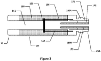
- FIGS 2 and 3 provide schematic diagrams of the control unit 20 and cartomiser 30 respectively of the e-cigarette of Figure 1 .
- the control unit 20 includes a battery 210 and control circuitry including a circuit board 215 to provide control functionality for the e-cigarette, e.g. by provision of a (micro)controller, processor, ASIC or similar form of control chip.
- the control chip may be mounted to a printed circuit board (PCB).
- the battery 210 is typically cylindrical in shape, and has a central axis that lies along, or at least close to (and generally parallel with), the longitudinal axis LA of the e-cigarette.
- the circuit board 215 is shown longitudinally spaced from the battery 210, in the opposite direction to the cartridge 30 (see Figure 1 ).
- the skilled person will be aware of various other potential locations for the circuit board 215, for example, at the opposite end of the battery 210 to that shown.
- the circuit board 215 lies along a side of the battery 210.
- the circuit board 215 might be located adjacent one outer wall of the control unit 20, with the battery 210 slightly offset towards the opposite outer wall of the control unit 10.
- circuit board 215 may be split across multiple circuit boards and/or across components which are not mounted to a PCB, and these additional components and/or PCBs can be located as appropriate within the e-cigarette 10.
- functionality of the circuit board 215 for controlling the (re)charging functionality of the battery 210 may be provided separately (e.g. on a different PCB) from the functionality for controlling the discharge - i.e. for providing power to the heater of the cartomiser 30 from the battery 210.
- the circuit board 215 in the example shown also includes a sensor unit. If a user inhales on the mouthpiece 35, air is drawn into the e-cigarette 10 through one or more air inlet holes (not shown in Figures 1 and 2 ).
- the sensor unit which may include a pressure sensor and/or microphone, detects this airflow, and in response to such a detection, the circuit board 215 provides power from the battery 210 to the heater in the cartomiser 30 (this is generally referred to as puff actuation).
- the e-cigarette 10 may be provided with a button or switch that a user can operate to provide power from the battery to the heater.
- the control unit 20 also includes an electrical connector having an integrated temperature sensor, as discussed later with reference to Figures 4 through 7 .
- the cartomiser 30 includes an air passage 161 extending along the central (longitudinal) axis of the cartomiser 30 (and e-cigarette 10) from the mouthpiece 35 to the connector 25A, which joins the cartomiser to the control unit 20.
- a reservoir of e-liquid 160 is provided around the air passage 161. This reservoir 160 may be implemented, for example, by providing cotton or foam soaked in the e-liquid, or in other implementations, the e-liquid may be held freely within a suitable container.
- the cartomiser 30 also includes a heater 155 in the form of a coil for heating e-liquid from reservoir 160 to generate vapour to flow through air passage 161 and out through mouthpiece 35.
- the heater 155 is powered through lines 166 and 167, which are in turn connected to opposing polarities (positive and negative, or vice versa) of the battery 210 via connector 25A.
- some embodiments of the cartomiser 30 may include a heater temperature sensor configured to sense a temperature of the heater 155.
- the heater temperature sensor is disposed in the cartomiser 30 but coupled to the circuit board 215, e.g., through connectors 25A and 25B. Accordingly, the circuit board 215 is able to control the power supplied to the heater 155 based on the current temperature of the heater 155.
- the connectors 25A and 25B provide mechanical and electrical connectivity between the control unit 20 and the cartomiser 30.
- the connector 25B includes two electrical terminals, an outer contact 240 and an inner contact 250, which are separated by insulator 260.
- the connector 25A likewise includes an inner electrode 175 and an outer electrode 171, separated by insulator 172, as seen in Figure 3 ).
- the inner electrode 175 and the outer electrode 171 of the cartomiser 30 mechanically (and hence electrically) engage the inner contact 250 and the outer contact 240 respectively of the control unit 20.
- the inner contact 250 is mounted on a coil spring 255 so that during the mating (connection) process, the inner electrode 175 pushes against the inner contact 250 to compress the coil spring 255, thereby helping to ensure good mechanical and electrical contact when the cartomiser 30 is connected to the control unit 20.
- the cartomiser connector 25A of Figure 3 is also provided with two lugs or tabs 180A, 180B, which extend in opposite directions away from the longitudinal axis of the e-cigarette. These tabs are used to provide the bayonet fitting for connecting the cartomiser 30 to the control unit 20.
- FIG. 4 shows schematically, a control unit 320 in accordance with some embodiments.
- Control unit 320 is generally similar to control unit 20 as discussed above.
- Various components and details, e.g. such as wiring and more complex shaping, have been omitted from Figure 4 for reasons of clarity.
- Control unit 320 comprises control circuitry, which includes circuit board 315, as well as a battery 310, external connectors 325B, 327, and an electrical connector 390.
- the circuit board 315 is substantially similar to circuit board 215 described above, and is configured to control one or more functions of the electronic aerosol provision system, e.g., controlling power supplied from the battery 310 to the heater 155 of cartomiser 30.
- the functions of the circuit board 315 may be spread over one or more physical components, e.g., one or more PCBs.
- one PCB may be provided for controlling the supply of power to the heater of the cartomiser 30, while another, physically separate, PCB may be provided for controlling the re-charging of the battery 310 from an external source.
- the circuit board 315 lies between the battery 310 and a connector 325B for attaching to a cartomiser.
- the battery 310 is substantially similar to battery 210 as described above. Generally the battery 310 supplies power to the control circuitry and other components of the e-cigarette 10, and may be recharged by connecting to a suitable re-charging system, for example via connection or port 327 (as described in more detail below). In some embodiments, the battery 310 may be a lithium-Ion battery.
- the connector 325B is located at one end 302 of control unit 320, and is similar to connector 25B shown in Figure 1 .
- the control unit 320 is provided with a further connector 327, which is located at the tip end 304, opposite to the end 302 (the tip end 304 is therefore furthest from mouthpiece 35).
- the connector 327 is used to connect to an external power source, such as a charging system, for providing power to re-charge the battery 310.
- the connection 327 may be a (micro or mini) USB port or similar that enables connection to mains electricity or other power supply via a suitable lead and adapter.
- Such a connection may also facilitate data transfer, such as data pertaining to the usage of the electric aerosol provision system, when connected to a personal computer or the like.
- the connection 327 may be a conductive plate that enables inductive power transfer when placed in the vicinity of a suitably configured inductive charging system.
- the positioning of the battery 310 and the circuit board 315 within the control unit 320 shown in Figure 4 is one of many possible configurations.
- the circuit board 315 may be disposed closer to the tip end 304 than the battery 310; see, for example, Figure 2 .
- the circuit board 315 may be placed to the side of the battery 310, e.g., to the left or right in Figure 4 .
- the positioning of the circuit board 315 is not limited to the particular configuration shown, but may be arranged depending upon the spatial limitations and construction of a given control unit 320.
- the control unit 320 is provided with an electrical connector 390 that provides an electrical connection between the battery 310 and the circuit board 315.
- the electrical connector 390 is shown in Figure 4 as extending from a lower part of the battery 310, i.e. nearest tip end 304, along the length of the battery 310, and to the circuit board 315.
- the electrical connector 390 may be routed as appropriate for the relative positions of the battery 310 and circuit board 315 within the control unit 320.
- the electrical conductor 390 may be used to link the battery 310 and the connector 325B (with or without connecting to the PCT 315), or to provide any other desired connectivity within control unit 320 for the transmission or electrical power and/or signals.
- the electrical connector 390 comprises a flat flexible cable (FFC), also termed a flex cable.
- FFC flat flexible cable
- a flex cable is similar in some respects to a PCB, in that it may include (small) mounted components, and conductive tracks for electrically linking the components and supplying other conductive paths, e.g. for external connection.
- a conventional PCB is formed with a solid substrate (board)
- a flex cable is formed on a flexible, laminated substrate.
- a flex cable for the electrical connector 390 has various advantages, for example, the flex cable can be formed separately from the rest of control unit 320, and then incorporated (assembled) as a single component supporting multiple conductive paths into the e-cigarette (rather than say having to fit multiple wires individually into the control unit 320, which would be a more cumbersome procedure).
- the flex cable 390 is shown in Figure 4 such that the plane of the flat flexible conductor is perpendicular to the page - i.e. the flex cable is shown edge-on. It will be appreciated that Figure 4 is not to scale, and for ease of understanding, the thickness of the flex cable is shown larger relative to the size of battery 310 than will be the case in most practical implementations. In addition, for ease of representation, the flex cable 390 is shown with angular corners at either end (to connect with the circuit board 315 and the tip end of the battery), however, in practice these corners would generally be smooth or rounded.
- the flex cable is shown (highly schematically) in Figure 4 as comprising a laminated structure formed from a conductive layer 393 sandwiched between a first electrical insulating layer 391 and a second electrical insulating layer 392.
- the conductive layer 393 typically includes a plurality of conductor tracks (not visible).
- Also mounted within the flex cable is a temperature sensor 394. Note that the first and second electrical insulating layers 391, 392 in effect provide a protective seal or coating for the conductive layer 393 and temperature sensor 394, and also provide electrical insulation of the conductive layer 393 and temperature sensor 394, e.g. from other components in the control unit 320.
- the first and second electrical insulating layers 391 and 392 are formed of a flexible dielectric material.
- the same material, or different materials, may be used for each of the layers 391, 392, providing the flexibility and heat expansion properties of the materials of each layer are suitably matched.
- the second electrical insulating layer 392 (or conversely the first electrical insulating layer 391) may be omitted - this is then more closely analogous to a PCB which has a rigid substrate for a base, but which is open at the top.
- the use of a flexible material for connector 390 provides the ability to manipulate the electrical 390 into various different desired configurations or shapes. This can help the flexible connector (cable) 390 to make good use of limited space within the control unit 320, for example, to follow a curved path between other components inside the control unit 30.
- first and/or second electrical insulating layers 391, 392 examples are polyester or polyimide (amongst others).
- the first and/or second electrical insulating layers 391, 392 typically have a thickness between 0.05 to 0.3 mm, e.g. 0.1-0.2 mm, although other thicknesses are possible. It should also be noted that the thickness of each of the first and second electrical insulating layers 391, 392 does not have to be the same.
- the flex cable should generally be configured to support an efficient transfer of thermal energy between the temperature sensor 394, which is sandwiched between these two insulating layers, and the internal environment of the control unit 320, especially the battery 310, thereby providing a more accurate measure of the current battery temperature.
- the flex cable for supporting this good thermal transfer are described in more detail below.
- the conductive layer 393 is provided on a surface of the first electrical insulating layer 391 and enables electrical connection between the battery 310 and the circuit board 315 to provide power from the former to the latter. N.B. it is assumed in Figure 4 that both terminals of the battery are located adjacent the tip end; however, if one battery terminal is located at each end of the battery, a separate connector (flex or otherwise) may be provided to support the additional electrical link from the circuit board 315 to the nearest end of the battery.
- the conductive layer 393 may provide further electrical connectivity between various power points and/or signal points within the control unit 320.
- the conductor layer 393 is formed from an electrically conductive material, for example, strips of copper deposited as tracks onto the first insulating layer 391.
- the number of conductor tracks in conductive layer 393 lies in the range between 2 and 10 (although a flex cable is generally able to support a higher number of tracks if so desired).
- Such tracks may be provided substantially parallel to one another with a pitch (distance between adjacent conductor strips or tracks) of between 0.5 and 1.5 mm, although the spacing may be greater to accommodate the temperature sensor 394, at least in the region surrounding this sensor. It will be appreciated that these ranges for the number and spacing of tracks are provided by way of example only, and other values may be used.
- the ends of the conductive tracks may be provided with suitable pads, lands, etc, for forming electrical connections between the flex cable 390 and other components.
- the other components may be connected by wires to the flex cable 390, or the flex cable may be configured to connect directly to a connector on another component.
- the wires or other connectors may be attached to the flex cable, e.g. by soldering, clamping or screwing, etc.
- a connector might be mounted to the flex cable 390, and the other components can then link into this connector.
- the conductive layer 393 typically has a thickness less than the thickness of the first and/or second insulating layers.
- the conductive layer may have a thickness of about 0.05 mm.
- the relatively thin conductor layer 393 provides flexibility which is compatible with the flexibility of the insulating layers 391, 392 (and hence for the overall connector 390).
- the space between the tracks of the conductive layer 393 may be filled with a suitable insulator - one possibility is that the first and second insulating layers 391, 392 are bonded to each other in these intervening regions.
- the thickness of the flex cable 390 typically is within the range of 0.25 mm to 0.4 mm, e.g. 0.3 mm.
- the overall thickness may be slightly greater at the location of the temperature sensor 394, e.g. by an additional 0.1-0.2 mm, as the first and second insulating layers 391, 392 flex or distort slightly to accommodate the temperature sensor 394 (or any other similar components, not shown in Figure 4 ).
- the temperature sensor 394 and the conductive layer 393 are sandwiched between the first and second electrically insulating layers 391, 392 in a laminated structure.
- the temperature sensor 394 may have soldered electrical connections to the conductive tracks in layer 393, or any other suitable form of bonding may be used. These conductive tracks can be used to provide power from the battery to the temperature sensor 394, and may also be used for signalling to/from the temperature sensor.
- the temperature sensor 394 is positioned on the first electrical insulating layer 391 such that, when the flex cable 390 is connected between the battery 310 and the circuit board 315, the temperature sensor 394 is located at least close (adjacent) to the battery 310.
- the temperature sensor may be in direct contact with the battery.
- the temperature sensor may protrude through one of the laminated layers to contact the battery, or a portion of one of the first or second insulating layers 391 may be omitted (removed) to allow direct contact between the battery and the temperature sensor.
- the temperature sensor 394 is in indirect contact with the battery 310 through one of the insulating layers.
- the temperature sensor is configured to be in good thermal contact with the battery 310 so as to be able to determine a change in temperature of the battery.
- any suitable type of temperature sensor can be used as the temperature sensor 394.
- Typical examples include resistance temperature devices (RTDs) and thermocouple devices.
- the temperature sensor 394 is sensitive to temperature at least across a specified operating range of the battery 310, for example, 0 °C to 60 °C.
- the temperature sensor 394 monitors a physical parameter, such as voltage and/or current, that is indicative of the temperature of the battery 310.
- the temperature sensor 394 may monitor the resistance of a component which varies with temperature, or the voltage output of a thermocouple.
- the temperature sensor 394 may be linked by the conductive layer to a controller (e.g. processor, microcontroller, etc) on the circuit board 315.
- the temperature sensor 394 outputs the measured temperature to the controller, which monitors the temperature, and is used to regulate one or more functions of the electronic aerosol provision system based upon this measured temperature of the battery 310. For example, the controller may shut down or at least reduce the amount of power taken from the battery if the measured temperature is found to be outside the specified operating temperature range of the battery.
- the temperature sensor 394 itself may be responsible for monitoring whether the measured temperature is within the specified operating temperature range of the battery, and if not, sending a suitable alarm signal to the controller to perform appropriate action(s) in response to this error condition.
- Figure 5 is a schematic illustration of a portion of an electrical connector 490, having a first electrical insulating layer 491, a plurality of conductor strips 493 and a temperature sensor 494 (these generally correspond to the electrical conductor 390, first insulating layer 391, conductive layer 393 and temperature sensor 394 of Figure 4 , respectively).
- the electrical connector 490 may be provided with a second insulating layer (not shown in Figure 5 ), overlying the conductor strips 493 and corresponding to the second insulating layer 392, however this may be omitted in some embodiments.
- the plurality of conductor strips 493 include lines 495A and 495B that extend through the portion of the flexible electrical connector 493 shown in Figure 5 . These two lines 495A and 495B may, for example, be used to connect positive and negative terminals on the battery 310 to the circuit board 315 (as shown in Figure 3 ). As mentioned above, the power lines 495A, 495B may be provided with suitable connection facilities at each end for this purpose (pad, flip-lock connector, etc).
- Figure 5 additionally shows (in very schematic form) one possible configuration in which the temperature sensor 494 may be arranged on the surface of the first electrical insulating layer 491.
- a temperature sensor conductor strip 496 is provided and enables electrical connection of the temperature sensor 494.
- conductor strip 496 may comprise multiple individual (separate) lines (not shown in Figure 5 ).
- the conductor strip is shown extending in only one direction from temperature sensor 494, it may extend in both directions, depending upon the desired electrical connectivity for the temperature sensor 494.
- the conductor strip 496 may provide positive and negative power supply lines to the temperature sensor 494.
- the power supply could be received from the battery 310 or alternatively from the circuit board 315 (e.g. from a processor on circuit board 315).
- the power supply to the temperature sensor 494 (or at least one line thereof) may instead branch off from the power supply lines between the battery 310 and the circuit board 315, e.g. by connection to lines 495A and 495B (such connection is not shown in Figure 5 ), or utilise a connection to a ground plane (if provided).
- the temperature sensor 494 may incorporate its own internal power source, e.g. a small battery.
- the temperature sensor 494 will generally be provided, for example as part of conductor strip 496, with at least one output signalling line and (in some implementations) at least one input control line.
- the signalling line and the input control line will typically link the temperature sensor 494 to the circuit board 315, and more particularly to control functionality located on this circuit board, such as a microcontroller, processor, etc.
- the signalling and control may utilise one or more shared lines.
- the signalling and/or control may be implemented over one or both of the power lines, e.g. by using an appropriate modulation scheme to encode signals.
- the output signalling link may be used by the temperature sensor to output the measured temperature to the circuit board 315, which is then responsible for monitoring the measured temperature for any out-of-operating range condition.
- the temperature sensor may use the output signalling link to send an alarm to the circuit board 315 to report an error condition corresponding to an out-of-range temperature measurement (this may include an indication of whether the sensed temperature is too high or too low).
- an input control link may be provided and used by the circuit board 315 (or other appropriate control functionality) for example to set, in the temperature sensor 494, upper and lower thresholds for an allowable operating range. In this case, a measured temperature above the upper threshold or below the lower threshold would then trigger an alarm for an out-of-range temperature measurement
- the temperature sensor 494 is a resistance temperature detector (RTD), whose resistance is a function of temperature.
- RTD resistance temperature detector
- a fixed reference current may be supplied by the circuit board 315 to the RTD, and the circuit board 315 also monitors the voltage across the RTD. If the battery temperature changes, this will in turn change the temperature, and hence resistance, of the RTD (temperature sensor 494).
- the voltage monitored by the circuit board (or other suitable facility within the e-cigarette) will change with a change in resistance, and this is indicative of a change in the temperature of the battery 310.
- the temperature sensor 494 may be a thermocouple device or any other suitable temperature sensor for detecting a temperature variation associated with the battery 310.
- the temperature sensor 494' is formed within conductive layer 493 by altering the shape, material and/or form (etc) of a conductor strip 496' which connects to the temperature sensor 494'. Forming the temperature sensor 494' within or as part of the conductor strip 496' helps to reduce the overall thickness of the flexible electrical connector 490' (compared, for example, with the configuration of Figure 5 , in which the temperature sensor 494' is formed as an additional component which may be mounted on the conductor strip 496).
- the temperature sensor 494' is formed by reducing the width of a portion of the conductor strip 496' (rather than by incorporating a distinct, additional component into the electrical conductor 490'). This reduced width portion has a higher resistance, and so may provide a relatively large proportion of the total resistance along conductor strip 496'.
- the temperature sensor 494' may be formed from the same material as conductor strip 496' or from a different material - e.g. one which has a greater variation of resistance with temperature - i.e. a higher thermal coefficient of resistivity.
- a temperature change impacts the resistance of this reduced width portion, namely temperature sensor 494'. This then allows the temperature change to be detected, e.g. on circuit board 315, by monitoring the overall resistance of conductor strip 496'.
- the temperature sensor 494' in this implementation can be considered as a form of RTD, and may receive a power supply (for example) directly from the battery 310 or from a component on PCB 315.
- Figure 7 depicts a simplified schematic view of a further embodiment of an electrical connector 590 as viewed from a direction perpendicular to the plane of the flex cable.
- the electrical connector 590 a flexible cable
- the electrical connector 590 is similar in many respects to the electrical connectors 390, 490, 490' described above.
- conductor strips 593 and a temperature sensor 594 are provided on a substrate 591 comprising a flexible first dielectric material to form a flex cable similar to that of Figures 5 and 6 .
- the temperature sensor 594 is shown as having a circular shape, but this is schematic, and any appropriate shape for the device may be used, such as rectangular, etc.
- the temperature sensor 594 is overlain by a layer or patch of a second material, designated by numeral 597, and shown in dashed outline, so that the temperature sensor 594 is in effect sandwiched between the substrate 591 and the layer 597.
- the layer 597 of the second material may cover all or just part of the temperature sensor 594, and may also be limited in extent so that it covers only the temperature sensor 594, without extending further over any other areas of the substrate 591.
- the remainder of the substrate 591 and conductor strips 593 (and temperature sensor 594, if appropriate) may be covered with a third dielectric layer (not shown in Figure 7 ), analogous to the flexible dielectric material of layer 392 (see Figure 4 ).
- the patch of the second material 597 can then be considered as a window within the third dielectric layer.
- the second material 597 has a higher heat transfer coefficient than the first and/or third dielectric materials 591 (as provided) to allow changes in the temperature of the battery 310 to be transferred through to the temperature sensor 594 more quickly and efficiently (than through the first or third dielectric material), thereby providing more sensitive readings of temperature, and with a better time response to changes in battery temperature.
- the second material 597 may be any suitable material that enables good thermal conductivity between the battery 310 and the temperature sensor 594.
- the second material 597 may in some implementations be more resistant to heat damage than other components of the flexible connector 590, if it is liable to experience a high temperature from being in contact with battery 310.
- the second material 597 may or may not be flexible, since it covers a relatively small area of the substrate 591, and so will not significantly contribute to the overall flexibility of connector 590.
- the second material 597 may or may not be dielectric (electrically insulating), depending, for example, on whether the battery surface and/or the temperature sensor are themselves provided with an electrically insulating external surface or coating.
- the choice of material for the second layer 597 may be broader than for the first material layer 591 (or third material layer).
- the third dielectric layer may be omitted.
- the second material 597 may also act as a spacer between the battery and the remainder of the flexible connector 590.
- the second layer 597 may be omitted, for example, to allow the temperature sensor 594 to directly contact the battery 310 through a suitable window or hole in the third dielectric layer.
- the temperature sensor was provided with its own dedicated conductor strip 496, 496'.
- the temperature sensor 594 may be located, for example, across two conductor strips 593 that are utilised to provide power from the battery 310 to the control board 315.
- the temperature sensor 594 may transmit temperature information in the form of a superimposed signal (or modulation) with respect to the power supply (such techniques and protocols for communicating in this way are known in the art and are not discussed in further detail herein); a similar approach could also be used to support control communications to the temperature sensor from the circuit board 315.
- Further circuit configurations will be apparent to the skilled person - e.g. where the temperature sensor 594 itself directly incorporates a switch to block the transmission of power on conductor lines 593 in the event that the sensed temperature is out of range.
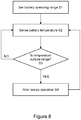
- FIG 8 illustrates a method of operating a control unit 320 for an e-cigarette 10 such as described herein in accordance with some embodiments.
- a suitable battery operating temperature range is set at step S1. This setting is generally performed at the time of manufacture, or automatically after manufacture (e.g. if a new battery unit is inserted, the control unit may access information supplied with the battery about the appropriate operating temperature range).
- the battery temperature is sensed by the temperature sensor 393, 494, 494'. Typically, this involves sensing a physical parameter, e.g. voltage or resistance, which is directly related to temperature.
- a check is made to see whether the sensed temperature is outside the specified range - if so, this is considered to be an error condition.
- the sensed temperature may be continually checked against an upper threshold value which, when surpassed, indicates that the battery 310 is operating at an unsafe temperature (too high).
- the upper threshold is set at 50° or 60°C (for example).
- the sensed temperature may also be compared against a lower temperature threshold, set (for example) at 0°C or -5°C.
- the threshold(s) or specified operating range may be dependent on certain other parameters, e.g. ambient temperature, or time, or rate of temperature change. For example, a momentary spike in temperature may be acceptable, but a longer excursion from the specified operating range may trigger an error condition; similarly, a rapid rise in temperature (i.e. greater than a threshold rate) may be considered an error condition in itself, irrespective of whether an upper temperature threshold has yet been breached.
- step S3 If an error condition is not detected at step S3, e.g. the sensed temperature lies within the specified operating temperature range (NO at step S3), then the temperature of the battery 310 is regarded as acceptable, and accordingly the e-cigarette 10 continues to function as normal.
- the processing loops back to S2, to indicate an ongoing monitoring of the temperature. Note that there may be a fixed or variable frequency of monitoring, e.g. the rate of sampling the temperature, as per S2, might increase as the sensed battery temperature approaches the edge of the allowed operating range.
- step S3 If, however, there is an error condition (YES at step S3) such that the sensed temperature is outside the specified operating range, e.g. above an upper threshold, then the device operation is altered accordingly at S4. Most typically this will involve reducing or ceasing the supply of power from the battery 310.
- this control (remedial) action is performed by the circuit board 315 (such as by a processor thereon), which receives the sensed temperature from the temperature sensor, performs the test of step S3, and then reduces or ceases the supply of power from the battery accordingly.
- the functionality of S3 and S4 may be integrated, at least in part, into the temperature sensor itself (although this will tend to be a less flexible approach).
- the major consumer of power from the battery 310 is usually the electrical heater 155. Therefore at S4, reducing or ceasing the power supply from the battery to the heater may be the main focus of the remedial action. However a wider shutdown of electrical operations may be required to address an over-temperature situation if, for example, this is caused by a short-circuit somewhere in the control unit 20.
- the circuit board 315 may cease the power supply from the battery 310 to the vaporiser 30 by operating a switch which can be located along this supply path.
- the power supply from the battery 310 to the vaporiser 30 may be subject to pulse width modulation (PWM), whereby the circuit board can increase a duty cycle from zero (no power) up to unity (full power).
- PWM pulse width modulation
- Some battery units 310 used in e-cigarettes directly incorporate support for such PWM functionality.
- the circuit board 315 (or other control facility) can therefore reduce the power taken from the battery 310 by reducing the duty cycle of the PWM supply; the power can then be turned off completely by reducing the duty cycle down to zero.
- the power taken from the battery 310 might initially be reduced. If the temperature continues to rise (or does not fall), despite this action, then the circuit board 315 might further reduce (or completely cease) the power supply taken from the battery.
- the circuit board 315 may reduce or cease the supply of a re-charging current to the battery 310, e.g. by appropriate switching.
- the error condition may be caused by a temperature which is too low, i.e. below a specified operating threshold of the battery.
- the circuit board 315 may reduce or cease supply of power from the battery in order to prevent the battery from operating at too low a temperature (which might potentially damage the battery, or cause the e-cigarette to operate only in a degraded fashion, e.g. if not enough power is available from the battery for the vaporiser to function correctly).
- the processing of step S4 may also include providing some notification of the error condition to the user.
- the e-cigarette 10 may be provided with one or more lights that can be illuminated in a specific manner (e.g. colour, temporal pattern, etc) to denote an error; likewise the e-cigarette 10 may include an audio output facility to provide a suitable sound warning that an error condition has occurred.
- step S4 in Figure 8 the processing returns to step S2 - in effect the temperature monitoring is continued. Accordingly, if the temperature returns (e.g. falls) to within the specified operating range, then normal operation of the device can resume.
- the return to normal operation may be subject to certain conditions and/or processing (in addition to the temperature falling back within the normal operating range). For example, a user might have to perform some specific action, e.g. pressing a reset button (especially for devices in which the error condition is flagged to the user via some suitable audio and/or visual user interface, as described above).
- the circuit board may also require a predetermined time delay before resuming normal operations, and/or the temperature might have to return to a value which is comfortably within specified operating range (e.g. by a predetermined amount), rather than just enter the very edge of the specified operating range.
- the circuit board may only partly restore power from the battery, e.g. so that the e-cigarette can only resume operations at a reduced power level, at least for an initial time period. Further such conditions may be imposed as appropriate.
- the approach described herein therefore provides an electronic aerosol provision system comprising: a vaporiser for generating an aerosol using electrical power; a battery (such as battery 310) for supplying electrical power to the vaporiser and to other components of the electronic aerosol provision system; a flat, flexible cable (such as connector 390) having a laminated structure and incorporating multiple conductor lines for transmitting electrical power and/or signals; and a temperature sensor incorporated into the flat, flexible cable and located adjacent the battery for sensing the temperature of the battery.
- the electronic aerosol provision system is configured to detect an error condition if the sensed temperature of the battery goes outside a specified operating range, and in response to such detection, to reduce or cease the supply of electrical power from the battery.
- the flat, flexible cable includes at least first and second insulating layers.
- the multiple conductor lines and the temperature sensor are sandwiched between the first and second insulating layers.
- the system may further include a control facility, and the flat flexible cable includes at least one conductor line for communicating signals between the control facility and the temperature sensor.
- the control facility is configured to reduce or cease the supply of electrical power from the battery in response to the detection of the error condition, and may also send control commands to the temperature sensor over the cable.
- the battery has a longitudinal axis, e.g. the battery is generally cylindrical in shape, such as shown in Figures 2 and 4 .
- the flat, flexible cable extends in a direction parallel to said longitudinal axis.
- the plane of the flat cable may lie approximately tangential to the external surface of the battery. This can then assist in locating the temperature sensor close to or touching the external surface of the battery for more accurate temperature sensing.
- the battery and the flat, flexible cable (plus related functionality) as described herein may be provided in a control unit for an electronic aerosol provision system.
- a control unit for an electronic aerosol provision system.
- Such a control unit can then be connected to a vaporiser to form the (overall) electronic aerosol provision system.
- the temperature sensor senses the temperature by incorporating a physical parameter, such as resistance, which is temperature-dependent.
- a physical parameter such as resistance
- the temperature sensor itself may measure and/or convert this physical parameter into a sensed temperature reading, on other cases, the measurement and/or conversion may be performed externally.
- the control circuit board 315 might measure the resistance (physical parameter) of the temperature sensor to derive the sensed temperature from this physical parameter.
- the detection of the error condition may be derived directly from the measurement of the physical parameter, as a form of temperature reading (but without formal conversion to a temperature value), assuming that the operating temperature range of the battery can be expressed in terms of a corresponding range for the value of the physical parameter.
- the approach described herein therefore utilises a flat, flexible cable (FFC, also flex cable), such as connector 390 in Figure 4 .
- the FFC may be formed as a laminated cable having two or more flat conductors laid in parallel at a given pitch (separation), and laminated between two layers of dielectric.
- an FFC can be used in an e-cigarette to provide an easy, reliable, flexible and miniaturised connection of multiple signal and/or power points located on different parts of the e-cigarette.
- the FFC would typically run across the battery cell in the control unit (re-usable segment) of the e-cigarette to transmit electrical power and signals as required.
- a temperature sensor is integrated within the laminates of the FFC, such as shown in Figure 4 , to monitor the temperature of the e-cigarette battery, primarily for safety reasons.
- the temperature sensor has ready access to power lines and signal lines that are already incorporated into the FFC.
- the FFC can allow the temperature sensor to be placed immediately adjacent the battery, for accurate and responsive temperature tracking, but the temperature sensor can still be protected (if so required) by one or more laminates of the FFC.
- the FFC is relatively easy to assemble and fasten into an e-cigarette during manufacture (compared, for example, to assembling an individual temperature sensor and associated wiring).
- the FFC also represents a compact solution which can readily fit (aided by its flexibility) into the confined internal space of an e-cigarette.
Landscapes
- Engineering & Computer Science (AREA)
- Power Engineering (AREA)
- Secondary Cells (AREA)
- Battery Mounting, Suspending (AREA)
- Protection Of Static Devices (AREA)
Description
- The present disclosure relates to electronic aerosol provision systems such as nicotine delivery systems, e.g. electronic cigarettes and the like.
- Electronic aerosol provision systems such as electronic cigarettes (e-cigarettes) generally contain a vapour precursor, e.g. a reservoir of liquid (e-liquid) including a formulation such as nicotine, from which an aerosol (vapour) is generated. An electronic aerosol provision system may comprise a heater arranged to receive liquid from the reservoir, for example through wicking or capillary action. When a user inhales on the device, electrical power is supplied to the heater to vaporise liquid from the vicinity of the heater to generate an aerosol for inhalation by the user through a mouthpiece.
- Such devices are usually provided with one or more air inlet holes located away from the mouthpiece end of the system. When a user sucks on a mouthpiece (located at the mouthpiece end of the system), air is drawn in through the inlet hole(s) and past the liquid that is being vaporised. This air flow continues along a flow path to the mouthpiece opening, carrying some of the aerosol (vapour) for inhalation by the user.
- Electronic aerosol provision systems typically include their own power source, such as a rechargeable battery. The battery supplies the power to the system, including to the heater to vaporise the liquid. Such a battery may have a range of normal operating temperatures, e.g., between 0°C and 60°C. If the battery becomes too hot, e.g., from prolonged use or from a malfunction of the system, the battery may potentially exceed this normal operating range of temperature. Such an excessive temperature may potentially cause damage to the battery itself and/or to other components of the electronic aerosol provision system.
-
US20030226837 describes an electrically heating smoking system wherein tobacco smoke is generated by heating a portion of a cigarette with an electrical resistance heating element powered by lithium ion battery cells. The lithium ion battery cells supply current to the electrical resistance heating element with current up to 20 times greater than the recommended discharge rate. To prevent damage to the lithium ion battery cells under such high discharge conditions, the smoking system includes a controller which provides modulated pulses of electrical power from the battery cells to the resistance heating element during smoking of the cigarette. -
CN105029713 describes a kind of assembly method of an electronic cigarette, comprising the following steps: (A) Get the raw materials ready : the accessory of electronic cigarette is assembled after preparation, all accessories are placed on same production line; (B) Assemble master control module; (C) Assemble new lithium battery; (D) Assemble output pin module;(E) Assemble FFC connecting lines. - Disclosed herein is an electronic aerosol provision system comprising: a vaporiser for generating an aerosol using electrical power; a battery for supplying electrical power to the vaporiser and to other components of the electronic aerosol provision system; a flat, flexible cable having a laminated structure and incorporating multiple conductor lines for transmitting electrical power and/or signals; and a temperature sensor incorporated into the flat, flexible cable and located adjacent the battery for sensing the temperature of the battery. The electronic aerosol provision system is configured to detect an error condition if the sensed temperature of the battery goes outside a specified operating range; and in response to such detection, to reduce or cease the supply of electrical power from the battery.
- Also disclosed herein are a method for operating such an electronic aerosol provision system, and a control unit for use in such an electronic aerosol provision system.
- Embodiments of the invention will now be described, by way of example only, with reference to the accompanying drawings, in which:
-
Figure 1 is a schematic (exploded) diagram illustrating an electronic aerosol provision system in accordance with some embodiments of the invention. -
Figure 2 is a schematic diagram of a control unit of the electronic aerosol provision system ofFigure 1 in accordance with some embodiments. -
Figure 3 is a schematic diagram of a cartomiser of the electronic aerosol provision system ofFigure 1 in accordance with some embodiments. -
Figure 4 is a schematic diagram of a control unit, such as for use in the electronic aerosol provision system ofFigure 1 , the control unit including a flexible electrical connector having an integrated temperature sensor in accordance with some embodiments. -
Figures 5-7 are more detailed schematic diagrams of the flexible electrical connector having an integrated temperature sensor ofFigure 4 in accordance with various embodiments. -
Figure 8 is a flow chart of a method, such as for use in the electronic aerosol provision system ofFigure 1 , for sensing the temperature of the battery and for controlling the electronic aerosol provision system in accordance with the sensed temperature in accordance with some embodiments. - Aspects and features of certain examples and embodiments are described herein. Some aspects and features of certain examples and embodiments may be implemented conventionally and these are not described in detail in the interests of brevity. It will thus be appreciated that aspects and features of apparatus and methods discussed herein which are not described in detail may be implemented in accordance with any conventional technique for implementing such aspects and features.
- Throughout the following description, the term "e-cigarette" is used interchangeably with electronic aerosol (vapour) provision system and other similar terms.
-
Figure 1 is a schematic diagram illustrating ane-cigarette 10 in accordance with some embodiments of the invention. Thee-cigarette 10 has a generally cylindrical shape, extending along a longitudinal axis indicated by dashed line LA, and comprises two main components, namely acontrol unit 20 and a cartomiser (cartridge) 30. The cross-section through the cylinder, i.e. in a plane perpendicular to the line LA, may be circular, elliptical, square, rectangular, hexagonal, or some other regular or irregular shape as desired. It should also be appreciated that embodiments ofe-cigarettes 10 may have shapes other than generally cylindrical, e.g., a generally ellipsoidal shape. - The
cartomiser 30 includes an internal chamber containing a reservoir of liquid formulation including e.g. nicotine, a vaporiser (such as a heater), and amouthpiece 35. Thecartomiser 30 may further include a wick or similar facility to transport liquid from the reservoir to the heater. - The
control unit 20 includes a power source, such as a battery or cell to provide power to thee-cigarette 10 and control circuitry (discussed in more detail below) for generally controlling various functions of thee-cigarette 10. When the heater receives power from the battery (not shown inFigure 1 ), as controlled by the control circuitry, the heater vaporises the liquid and this vapour (aerosol) is then inhaled by a user through themouthpiece 35. - In the embodiment shown in
Figure 1 , thecontrol unit 20 andcartomiser 30 are detachable from one another by separating in a direction parallel to the longitudinal axis LA, but are joined together when thedevice 10 is in use by a connection, indicated schematically as 25A (on the cartomiser 30) and 25B (on the control unit 20), to provide mechanical and electrical connectivity between thecontrol unit 20 and thecartomiser 30. In some embodiments, electrical induction may be employed to transfer power from thecontrol unit 20 to thecartomiser 30. Theconnectors cartomiser 30 to thecontrol unit 20. It will be appreciated that other embodiments may use a different form of connection between thecontrol unit 20 and thecartomiser 30, such as a snap fit or a screw connection. - The
connection 25B on thecontrol unit 20 that is used to connect to thecartomiser 30 may also serve as a socket for connecting a charging device (not shown) when the control unit is detached from thecartomiser 30. In some embodiments, thecontrol unit 20 may be provided with a conductive contact for re-charging at or near the end opposite theconnection 25B, for example, in the form of a mini or micro USB port. In this case, thecontrol unit 20 need not be separated from thecartomiser 30 to (re)charge the battery using such a port
In many devices, thecartomiser 30 is detached from thecontrol unit 20 for disposal of thecartomiser 30 when the supply of e-liquid is exhausted - and replaced with another cartomiser, if so desired. In contrast, thecontrol unit 20 is normally re-usable with a succession of cartomisers. -
Figures 2 and3 provide schematic diagrams of thecontrol unit 20 andcartomiser 30 respectively of the e-cigarette ofFigure 1 . Note that various components and details, e.g. such as wiring and more complex shaping, have been omitted fromFigures 2 and3 for reasons of clarity. As shown inFigure 2 , thecontrol unit 20 includes abattery 210 and control circuitry including acircuit board 215 to provide control functionality for the e-cigarette, e.g. by provision of a (micro)controller, processor, ASIC or similar form of control chip. The control chip may be mounted to a printed circuit board (PCB). Thebattery 210 is typically cylindrical in shape, and has a central axis that lies along, or at least close to (and generally parallel with), the longitudinal axis LA of the e-cigarette. - In
Figure 2 , thecircuit board 215 is shown longitudinally spaced from thebattery 210, in the opposite direction to the cartridge 30 (seeFigure 1 ). However, the skilled person will be aware of various other potential locations for thecircuit board 215, for example, at the opposite end of thebattery 210 to that shown. A further possibility is that thecircuit board 215 lies along a side of thebattery 210. For example, with ane-cigarette 10 having a rectangular cross-section, thecircuit board 215 might be located adjacent one outer wall of thecontrol unit 20, with thebattery 210 slightly offset towards the opposite outer wall of thecontrol unit 10. Note also that the functionality provided by thecircuit board 215 may be split across multiple circuit boards and/or across components which are not mounted to a PCB, and these additional components and/or PCBs can be located as appropriate within thee-cigarette 10. For example, the functionality of thecircuit board 215 for controlling the (re)charging functionality of thebattery 210 may be provided separately (e.g. on a different PCB) from the functionality for controlling the discharge - i.e. for providing power to the heater of thecartomiser 30 from thebattery 210. - The
circuit board 215 in the example shown also includes a sensor unit. If a user inhales on themouthpiece 35, air is drawn into thee-cigarette 10 through one or more air inlet holes (not shown inFigures 1 and 2 ). The sensor unit, which may include a pressure sensor and/or microphone, detects this airflow, and in response to such a detection, thecircuit board 215 provides power from thebattery 210 to the heater in the cartomiser 30 (this is generally referred to as puff actuation). In other implementations, the e-cigarette 10 may be provided with a button or switch that a user can operate to provide power from the battery to the heater. Although not shown explicitly inFigures 1 and 2 , thecontrol unit 20 also includes an electrical connector having an integrated temperature sensor, as discussed later with reference toFigures 4 through 7 . - As shown in
Figure 3 , thecartomiser 30 includes anair passage 161 extending along the central (longitudinal) axis of the cartomiser 30 (and e-cigarette 10) from themouthpiece 35 to theconnector 25A, which joins the cartomiser to thecontrol unit 20. A reservoir ofe-liquid 160 is provided around theair passage 161. Thisreservoir 160 may be implemented, for example, by providing cotton or foam soaked in the e-liquid, or in other implementations, the e-liquid may be held freely within a suitable container. Thecartomiser 30 also includes aheater 155 in the form of a coil for heating e-liquid fromreservoir 160 to generate vapour to flow throughair passage 161 and out throughmouthpiece 35. Theheater 155 is powered throughlines battery 210 viaconnector 25A. - Although not shown in
Figure 3 , some embodiments of thecartomiser 30 may include a heater temperature sensor configured to sense a temperature of theheater 155. The heater temperature sensor is disposed in thecartomiser 30 but coupled to thecircuit board 215, e.g., throughconnectors circuit board 215 is able to control the power supplied to theheater 155 based on the current temperature of theheater 155. - As mentioned above, the
connectors control unit 20 and thecartomiser 30. As seen inFigure 2 , theconnector 25B includes two electrical terminals, anouter contact 240 and aninner contact 250, which are separated byinsulator 260. Theconnector 25A likewise includes aninner electrode 175 and anouter electrode 171, separated byinsulator 172, as seen inFigure 3 ). When thecartomiser 30 is connected to thecontrol unit 20, theinner electrode 175 and theouter electrode 171 of thecartomiser 30 mechanically (and hence electrically) engage theinner contact 250 and theouter contact 240 respectively of thecontrol unit 20. Theinner contact 250 is mounted on acoil spring 255 so that during the mating (connection) process, theinner electrode 175 pushes against theinner contact 250 to compress thecoil spring 255, thereby helping to ensure good mechanical and electrical contact when thecartomiser 30 is connected to thecontrol unit 20. - The
cartomiser connector 25A ofFigure 3 is also provided with two lugs ortabs cartomiser 30 to thecontrol unit 20. -
Figure 4 shows schematically, acontrol unit 320 in accordance with some embodiments.Control unit 320 is generally similar to controlunit 20 as discussed above. Various components and details, e.g. such as wiring and more complex shaping, have been omitted fromFigure 4 for reasons of clarity. -
Control unit 320 comprises control circuitry, which includescircuit board 315, as well as abattery 310,external connectors electrical connector 390. Thecircuit board 315 is substantially similar tocircuit board 215 described above, and is configured to control one or more functions of the electronic aerosol provision system, e.g., controlling power supplied from thebattery 310 to theheater 155 ofcartomiser 30. As above, the functions of thecircuit board 315 may be spread over one or more physical components, e.g., one or more PCBs. For example, one PCB may be provided for controlling the supply of power to the heater of thecartomiser 30, while another, physically separate, PCB may be provided for controlling the re-charging of thebattery 310 from an external source. Note that in the implementation shown inFigure 4 , thecircuit board 315 lies between thebattery 310 and aconnector 325B for attaching to a cartomiser. - The
battery 310 is substantially similar tobattery 210 as described above. Generally thebattery 310 supplies power to the control circuitry and other components of the e-cigarette 10, and may be recharged by connecting to a suitable re-charging system, for example via connection or port 327 (as described in more detail below). In some embodiments, thebattery 310 may be a lithium-Ion battery. - The
connector 325B is located at oneend 302 ofcontrol unit 320, and is similar toconnector 25B shown inFigure 1 . Thecontrol unit 320 is provided with afurther connector 327, which is located at thetip end 304, opposite to the end 302 (thetip end 304 is therefore furthest from mouthpiece 35). Theconnector 327 is used to connect to an external power source, such as a charging system, for providing power to re-charge thebattery 310. For example, theconnection 327 may be a (micro or mini) USB port or similar that enables connection to mains electricity or other power supply via a suitable lead and adapter. Such a connection may also facilitate data transfer, such as data pertaining to the usage of the electric aerosol provision system, when connected to a personal computer or the like. Another possibility is that theconnection 327 may be a conductive plate that enables inductive power transfer when placed in the vicinity of a suitably configured inductive charging system. - It will be appreciated that the positioning of the
battery 310 and thecircuit board 315 within thecontrol unit 320 shown inFigure 4 is one of many possible configurations. For example, thecircuit board 315 may be disposed closer to thetip end 304 than thebattery 310; see, for example,Figure 2 . In other configurations, thecircuit board 315 may be placed to the side of thebattery 310, e.g., to the left or right inFigure 4 . Accordingly, the positioning of thecircuit board 315 is not limited to the particular configuration shown, but may be arranged depending upon the spatial limitations and construction of a givencontrol unit 320. - The
control unit 320 is provided with anelectrical connector 390 that provides an electrical connection between thebattery 310 and thecircuit board 315. Theelectrical connector 390 is shown inFigure 4 as extending from a lower part of thebattery 310, i.e.nearest tip end 304, along the length of thebattery 310, and to thecircuit board 315. However, one skilled in the art will appreciate that theelectrical connector 390 may be routed as appropriate for the relative positions of thebattery 310 andcircuit board 315 within thecontrol unit 320. A further possibility is that theelectrical conductor 390 may be used to link thebattery 310 and theconnector 325B (with or without connecting to the PCT 315), or to provide any other desired connectivity withincontrol unit 320 for the transmission or electrical power and/or signals. - The
electrical connector 390 comprises a flat flexible cable (FFC), also termed a flex cable. Such a flex cable is similar in some respects to a PCB, in that it may include (small) mounted components, and conductive tracks for electrically linking the components and supplying other conductive paths, e.g. for external connection. However, whereas a conventional PCB is formed with a solid substrate (board), a flex cable is formed on a flexible, laminated substrate. The use of a flex cable for theelectrical connector 390 has various advantages, for example, the flex cable can be formed separately from the rest ofcontrol unit 320, and then incorporated (assembled) as a single component supporting multiple conductive paths into the e-cigarette (rather than say having to fit multiple wires individually into thecontrol unit 320, which would be a more cumbersome procedure). - The
flex cable 390 is shown inFigure 4 such that the plane of the flat flexible conductor is perpendicular to the page - i.e. the flex cable is shown edge-on. It will be appreciated thatFigure 4 is not to scale, and for ease of understanding, the thickness of the flex cable is shown larger relative to the size ofbattery 310 than will be the case in most practical implementations. In addition, for ease of representation, theflex cable 390 is shown with angular corners at either end (to connect with thecircuit board 315 and the tip end of the battery), however, in practice these corners would generally be smooth or rounded. - The flex cable is shown (highly schematically) in
Figure 4 as comprising a laminated structure formed from aconductive layer 393 sandwiched between a first electrical insulatinglayer 391 and a second electrical insulatinglayer 392. Theconductive layer 393 typically includes a plurality of conductor tracks (not visible). Also mounted within the flex cable is atemperature sensor 394. Note that the first and second electrical insulatinglayers conductive layer 393 andtemperature sensor 394, and also provide electrical insulation of theconductive layer 393 andtemperature sensor 394, e.g. from other components in thecontrol unit 320. - The first and second electrical insulating
layers layers connector 390 provides the ability to manipulate the electrical 390 into various different desired configurations or shapes. This can help the flexible connector (cable) 390 to make good use of limited space within thecontrol unit 320, for example, to follow a curved path between other components inside thecontrol unit 30. - Examples of a suitable flexible dielectric material for the first and/or second electrical insulating layers are polyester or polyimide (amongst others). The first and/or second electrical insulating
layers layers layers temperature sensor 394, which is sandwiched between these two insulating layers, and the internal environment of thecontrol unit 320, especially thebattery 310, thereby providing a more accurate measure of the current battery temperature. Various potential configurations of the flex cable for supporting this good thermal transfer are described in more detail below. - In the implementation shown in
Figure 4 , theconductive layer 393 is provided on a surface of the first electrical insulatinglayer 391 and enables electrical connection between thebattery 310 and thecircuit board 315 to provide power from the former to the latter. N.B. it is assumed inFigure 4 that both terminals of the battery are located adjacent the tip end; however, if one battery terminal is located at each end of the battery, a separate connector (flex or otherwise) may be provided to support the additional electrical link from thecircuit board 315 to the nearest end of the battery. Theconductive layer 393 may provide further electrical connectivity between various power points and/or signal points within thecontrol unit 320. - The
conductor layer 393 is formed from an electrically conductive material, for example, strips of copper deposited as tracks onto the first insulatinglayer 391. In some embodiments, the number of conductor tracks inconductive layer 393 lies in the range between 2 and 10 (although a flex cable is generally able to support a higher number of tracks if so desired). Such tracks may be provided substantially parallel to one another with a pitch (distance between adjacent conductor strips or tracks) of between 0.5 and 1.5 mm, although the spacing may be greater to accommodate thetemperature sensor 394, at least in the region surrounding this sensor. It will be appreciated that these ranges for the number and spacing of tracks are provided by way of example only, and other values may be used. - The ends of the conductive tracks may be provided with suitable pads, lands, etc, for forming electrical connections between the
flex cable 390 and other components. For example, the other components may be connected by wires to theflex cable 390, or the flex cable may be configured to connect directly to a connector on another component. The wires or other connectors may be attached to the flex cable, e.g. by soldering, clamping or screwing, etc. In other implementations, a connector might be mounted to theflex cable 390, and the other components can then link into this connector. - As mentioned above, it should be appreciated that
Figure 4 is not to scale, and theconductive layer 393 typically has a thickness less than the thickness of the first and/or second insulating layers. For example, the conductive layer may have a thickness of about 0.05 mm. The relativelythin conductor layer 393 provides flexibility which is compatible with the flexibility of the insulatinglayers 391, 392 (and hence for the overall connector 390). Note that the space between the tracks of theconductive layer 393 may be filled with a suitable insulator - one possibility is that the first and second insulatinglayers - The thickness of the
flex cable 390 typically is within the range of 0.25 mm to 0.4 mm, e.g. 0.3 mm. The overall thickness may be slightly greater at the location of thetemperature sensor 394, e.g. by an additional 0.1-0.2 mm, as the first and second insulatinglayers Figure 4 ). - As shown in
Figure 4 , thetemperature sensor 394 and theconductive layer 393 are sandwiched between the first and second electrically insulatinglayers temperature sensor 394 may have soldered electrical connections to the conductive tracks inlayer 393, or any other suitable form of bonding may be used. These conductive tracks can be used to provide power from the battery to thetemperature sensor 394, and may also be used for signalling to/from the temperature sensor. - The
temperature sensor 394 is positioned on the first electrical insulatinglayer 391 such that, when theflex cable 390 is connected between thebattery 310 and thecircuit board 315, thetemperature sensor 394 is located at least close (adjacent) to thebattery 310. In some implementations, the temperature sensor may be in direct contact with the battery. For example, the temperature sensor may protrude through one of the laminated layers to contact the battery, or a portion of one of the first or second insulatinglayers 391 may be omitted (removed) to allow direct contact between the battery and the temperature sensor. Another possibility is that thetemperature sensor 394 is in indirect contact with thebattery 310 through one of the insulating layers. In any event, the temperature sensor is configured to be in good thermal contact with thebattery 310 so as to be able to determine a change in temperature of the battery. - It should be appreciated that any suitable type of temperature sensor can be used as the
temperature sensor 394. Typical examples include resistance temperature devices (RTDs) and thermocouple devices. Thetemperature sensor 394 is sensitive to temperature at least across a specified operating range of thebattery 310, for example, 0 °C to 60 °C. In operation, thetemperature sensor 394 monitors a physical parameter, such as voltage and/or current, that is indicative of the temperature of thebattery 310. For example, thetemperature sensor 394 may monitor the resistance of a component which varies with temperature, or the voltage output of a thermocouple. - The
temperature sensor 394 may be linked by the conductive layer to a controller (e.g. processor, microcontroller, etc) on thecircuit board 315. Thetemperature sensor 394 outputs the measured temperature to the controller, which monitors the temperature, and is used to regulate one or more functions of the electronic aerosol provision system based upon this measured temperature of thebattery 310. For example, the controller may shut down or at least reduce the amount of power taken from the battery if the measured temperature is found to be outside the specified operating temperature range of the battery. Note that in other implementations, thetemperature sensor 394 itself may be responsible for monitoring whether the measured temperature is within the specified operating temperature range of the battery, and if not, sending a suitable alarm signal to the controller to perform appropriate action(s) in response to this error condition. -
Figure 5 is a schematic illustration of a portion of anelectrical connector 490, having a first electrical insulatinglayer 491, a plurality of conductor strips 493 and a temperature sensor 494 (these generally correspond to theelectrical conductor 390, first insulatinglayer 391,conductive layer 393 andtemperature sensor 394 ofFigure 4 , respectively). Theelectrical connector 490 may be provided with a second insulating layer (not shown inFigure 5 ), overlying the conductor strips 493 and corresponding to the second insulatinglayer 392, however this may be omitted in some embodiments. - In
Figure 5 , the plurality of conductor strips 493 includelines electrical connector 493 shown inFigure 5 . These twolines battery 310 to the circuit board 315 (as shown inFigure 3 ). As mentioned above, thepower lines -
Figure 5 additionally shows (in very schematic form) one possible configuration in which thetemperature sensor 494 may be arranged on the surface of the first electrical insulatinglayer 491. In this configuration, a temperaturesensor conductor strip 496 is provided and enables electrical connection of thetemperature sensor 494. Note that,conductor strip 496 may comprise multiple individual (separate) lines (not shown inFigure 5 ). In addition, although the conductor strip is shown extending in only one direction fromtemperature sensor 494, it may extend in both directions, depending upon the desired electrical connectivity for thetemperature sensor 494. - The
conductor strip 496 may provide positive and negative power supply lines to thetemperature sensor 494. The power supply could be received from thebattery 310 or alternatively from the circuit board 315 (e.g. from a processor on circuit board 315). The power supply to the temperature sensor 494 (or at least one line thereof) may instead branch off from the power supply lines between thebattery 310 and thecircuit board 315, e.g. by connection tolines Figure 5 ), or utilise a connection to a ground plane (if provided). Another possibility is that thetemperature sensor 494 may incorporate its own internal power source, e.g. a small battery. - The
temperature sensor 494 will generally be provided, for example as part ofconductor strip 496, with at least one output signalling line and (in some implementations) at least one input control line. The signalling line and the input control line will typically link thetemperature sensor 494 to thecircuit board 315, and more particularly to control functionality located on this circuit board, such as a microcontroller, processor, etc. In some cases the signalling and control may utilise one or more shared lines. In some cases, the signalling and/or control may be implemented over one or both of the power lines, e.g. by using an appropriate modulation scheme to encode signals. - In some implementations, the output signalling link may be used by the temperature sensor to output the measured temperature to the
circuit board 315, which is then responsible for monitoring the measured temperature for any out-of-operating range condition. In other implementations, the temperature sensor may use the output signalling link to send an alarm to thecircuit board 315 to report an error condition corresponding to an out-of-range temperature measurement (this may include an indication of whether the sensed temperature is too high or too low). - In some implementations, an input control link may be provided and used by the circuit board 315 (or other appropriate control functionality) for example to set, in the
temperature sensor 494, upper and lower thresholds for an allowable operating range. In this case, a measured temperature above the upper threshold or below the lower threshold would then trigger an alarm for an out-of-range temperature measurement
In some embodiments, thetemperature sensor 494 is a resistance temperature detector (RTD), whose resistance is a function of temperature. A fixed reference current may be supplied by thecircuit board 315 to the RTD, and thecircuit board 315 also monitors the voltage across the RTD. If the battery temperature changes, this will in turn change the temperature, and hence resistance, of the RTD (temperature sensor 494). Accordingly, the voltage monitored by the circuit board (or other suitable facility within the e-cigarette) will change with a change in resistance, and this is indicative of a change in the temperature of thebattery 310. In other implementations, thetemperature sensor 494 may be a thermocouple device or any other suitable temperature sensor for detecting a temperature variation associated with thebattery 310. - Another implementation of the flexible electrical connector 490' is shown schematically in
Figure 6 (it will be appreciated that flexible electrical connector 490' generally corresponds to flexibleelectrical connector 490 inFigure 5 , and flexibleelectrical connector 390 inFigure 4 , with an analogous correspondence for other reference numerals). The temperature sensor 494' is formed withinconductive layer 493 by altering the shape, material and/or form (etc) of a conductor strip 496' which connects to the temperature sensor 494'. Forming the temperature sensor 494' within or as part of the conductor strip 496' helps to reduce the overall thickness of the flexible electrical connector 490' (compared, for example, with the configuration ofFigure 5 , in which the temperature sensor 494' is formed as an additional component which may be mounted on the conductor strip 496). - In the implementation shown in
Figure 6 , the temperature sensor 494' is formed by reducing the width of a portion of the conductor strip 496' (rather than by incorporating a distinct, additional component into the electrical conductor 490'). This reduced width portion has a higher resistance, and so may provide a relatively large proportion of the total resistance along conductor strip 496'. The temperature sensor 494' may be formed from the same material as conductor strip 496' or from a different material - e.g. one which has a greater variation of resistance with temperature - i.e. a higher thermal coefficient of resistivity. - In operation, a temperature change impacts the resistance of this reduced width portion, namely temperature sensor 494'. This then allows the temperature change to be detected, e.g. on
circuit board 315, by monitoring the overall resistance of conductor strip 496'. Accordingly, the temperature sensor 494' in this implementation can be considered as a form of RTD, and may receive a power supply (for example) directly from thebattery 310 or from a component onPCB 315. -
Figure 7 depicts a simplified schematic view of a further embodiment of anelectrical connector 590 as viewed from a direction perpendicular to the plane of the flex cable. Theelectrical connector 590, a flexible cable, is similar in many respects to theelectrical connectors Figure 7 , conductor strips 593 and atemperature sensor 594 are provided on asubstrate 591 comprising a flexible first dielectric material to form a flex cable similar to that ofFigures 5 and6 . Note that inFigure 7 , thetemperature sensor 594 is shown as having a circular shape, but this is schematic, and any appropriate shape for the device may be used, such as rectangular, etc. - The
temperature sensor 594 is overlain by a layer or patch of a second material, designated bynumeral 597, and shown in dashed outline, so that thetemperature sensor 594 is in effect sandwiched between thesubstrate 591 and thelayer 597. Thelayer 597 of the second material may cover all or just part of thetemperature sensor 594, and may also be limited in extent so that it covers only thetemperature sensor 594, without extending further over any other areas of thesubstrate 591. The remainder of thesubstrate 591 and conductor strips 593 (andtemperature sensor 594, if appropriate), may be covered with a third dielectric layer (not shown inFigure 7 ), analogous to the flexible dielectric material of layer 392 (seeFigure 4 ). The patch of thesecond material 597 can then be considered as a window within the third dielectric layer. - The
second material 597 has a higher heat transfer coefficient than the first and/or third dielectric materials 591 (as provided) to allow changes in the temperature of thebattery 310 to be transferred through to thetemperature sensor 594 more quickly and efficiently (than through the first or third dielectric material), thereby providing more sensitive readings of temperature, and with a better time response to changes in battery temperature. - The
second material 597 may be any suitable material that enables good thermal conductivity between thebattery 310 and thetemperature sensor 594. In addition, thesecond material 597 may in some implementations be more resistant to heat damage than other components of theflexible connector 590, if it is liable to experience a high temperature from being in contact withbattery 310. - The
second material 597 may or may not be flexible, since it covers a relatively small area of thesubstrate 591, and so will not significantly contribute to the overall flexibility ofconnector 590. In addition, thesecond material 597 may or may not be dielectric (electrically insulating), depending, for example, on whether the battery surface and/or the temperature sensor are themselves provided with an electrically insulating external surface or coating. In this regard, the choice of material for thesecond layer 597 may be broader than for the first material layer 591 (or third material layer). - In some implementations, the third dielectric layer may be omitted. In this case the
second material 597 may also act as a spacer between the battery and the remainder of theflexible connector 590. In other implementations, thesecond layer 597 may be omitted, for example, to allow thetemperature sensor 594 to directly contact thebattery 310 through a suitable window or hole in the third dielectric layer. - In the implementations of
Figures 5 and6 , the temperature sensor was provided with its owndedicated conductor strip 496, 496'. In other implementations, such as shown inFigure 7 , thetemperature sensor 594 may be located, for example, across twoconductor strips 593 that are utilised to provide power from thebattery 310 to thecontrol board 315. In such a configuration, thetemperature sensor 594 may transmit temperature information in the form of a superimposed signal (or modulation) with respect to the power supply (such techniques and protocols for communicating in this way are known in the art and are not discussed in further detail herein); a similar approach could also be used to support control communications to the temperature sensor from thecircuit board 315. Further circuit configurations will be apparent to the skilled person - e.g. where thetemperature sensor 594 itself directly incorporates a switch to block the transmission of power onconductor lines 593 in the event that the sensed temperature is out of range. -
Figure 8 illustrates a method of operating acontrol unit 320 for an e-cigarette 10 such as described herein in accordance with some embodiments. A suitable battery operating temperature range is set at step S1. This setting is generally performed at the time of manufacture, or automatically after manufacture (e.g. if a new battery unit is inserted, the control unit may access information supplied with the battery about the appropriate operating temperature range). - At step S2, the battery temperature is sensed by the
temperature sensor battery 310 is operating at an unsafe temperature (too high). In some embodiments, the upper threshold is set at 50° or 60°C (for example). The sensed temperature may also be compared against a lower temperature threshold, set (for example) at 0°C or -5°C. In some embodiments, there may be only a single threshold check (i.e. the specified operating range is unbounded in the upper or lower direction). In some embodiments, the threshold(s) or specified operating range may be dependent on certain other parameters, e.g. ambient temperature, or time, or rate of temperature change. For example, a momentary spike in temperature may be acceptable, but a longer excursion from the specified operating range may trigger an error condition; similarly, a rapid rise in temperature (i.e. greater than a threshold rate) may be considered an error condition in itself, irrespective of whether an upper temperature threshold has yet been breached. - If an error condition is not detected at step S3, e.g. the sensed temperature lies within the specified operating temperature range (NO at step S3), then the temperature of the
battery 310 is regarded as acceptable, and accordingly thee-cigarette 10 continues to function as normal. In the context ofFigure 8 , the processing loops back to S2, to indicate an ongoing monitoring of the temperature. Note that there may be a fixed or variable frequency of monitoring, e.g. the rate of sampling the temperature, as per S2, might increase as the sensed battery temperature approaches the edge of the allowed operating range. - If, however, there is an error condition (YES at step S3) such that the sensed temperature is outside the specified operating range, e.g. above an upper threshold, then the device operation is altered accordingly at S4. Most typically this will involve reducing or ceasing the supply of power from the
battery 310. In some implementations, this control (remedial) action is performed by the circuit board 315 (such as by a processor thereon), which receives the sensed temperature from the temperature sensor, performs the test of step S3, and then reduces or ceases the supply of power from the battery accordingly. In some implementations, the functionality of S3 and S4 may be integrated, at least in part, into the temperature sensor itself (although this will tend to be a less flexible approach). - The major consumer of power from the
battery 310 is usually theelectrical heater 155. Therefore at S4, reducing or ceasing the power supply from the battery to the heater may be the main focus of the remedial action. However a wider shutdown of electrical operations may be required to address an over-temperature situation if, for example, this is caused by a short-circuit somewhere in thecontrol unit 20. - The
circuit board 315 may cease the power supply from thebattery 310 to thevaporiser 30 by operating a switch which can be located along this supply path. In some implementations, the power supply from thebattery 310 to thevaporiser 30 may be subject to pulse width modulation (PWM), whereby the circuit board can increase a duty cycle from zero (no power) up to unity (full power). Somebattery units 310 used in e-cigarettes directly incorporate support for such PWM functionality. The circuit board 315 (or other control facility) can therefore reduce the power taken from thebattery 310 by reducing the duty cycle of the PWM supply; the power can then be turned off completely by reducing the duty cycle down to zero. In some implementations, if the temperature goes above the specified range, the power taken from thebattery 310 might initially be reduced. If the temperature continues to rise (or does not fall), despite this action, then thecircuit board 315 might further reduce (or completely cease) the power supply taken from the battery. - Although the above description has focussed on an error condition that might arise during vaping, an error condition might also arise in other circumstances - e.g. as part of re-charging the
battery 310. In response to an error condition during re-charging, the circuit board 315 (or other appropriate control facility) may reduce or cease the supply of a re-charging current to thebattery 310, e.g. by appropriate switching. In addition, in some cases the error condition may be caused by a temperature which is too low, i.e. below a specified operating threshold of the battery. In this case, thecircuit board 315 may reduce or cease supply of power from the battery in order to prevent the battery from operating at too low a temperature (which might potentially damage the battery, or cause the e-cigarette to operate only in a degraded fashion, e.g. if not enough power is available from the battery for the vaporiser to function correctly). - The processing of step S4 may also include providing some notification of the error condition to the user. For example, the e-cigarette 10 may be provided with one or more lights that can be illuminated in a specific manner (e.g. colour, temporal pattern, etc) to denote an error; likewise the e-cigarette 10 may include an audio output facility to provide a suitable sound warning that an error condition has occurred.
- After the error condition is handled at step S4 in
Figure 8 , the processing returns to step S2 - in effect the temperature monitoring is continued. Accordingly, if the temperature returns (e.g. falls) to within the specified operating range, then normal operation of the device can resume. - In some implementations, the return to normal operation may be subject to certain conditions and/or processing (in addition to the temperature falling back within the normal operating range). For example, a user might have to perform some specific action, e.g. pressing a reset button (especially for devices in which the error condition is flagged to the user via some suitable audio and/or visual user interface, as described above). The circuit board may also require a predetermined time delay before resuming normal operations, and/or the temperature might have to return to a value which is comfortably within specified operating range (e.g. by a predetermined amount), rather than just enter the very edge of the specified operating range. In some cases, the circuit board may only partly restore power from the battery, e.g. so that the e-cigarette can only resume operations at a reduced power level, at least for an initial time period. Further such conditions may be imposed as appropriate.
- The approach described herein therefore provides an electronic aerosol provision system comprising: a vaporiser for generating an aerosol using electrical power; a battery (such as battery 310) for supplying electrical power to the vaporiser and to other components of the electronic aerosol provision system; a flat, flexible cable (such as connector 390) having a laminated structure and incorporating multiple conductor lines for transmitting electrical power and/or signals; and a temperature sensor incorporated into the flat, flexible cable and located adjacent the battery for sensing the temperature of the battery. The electronic aerosol provision system is configured to detect an error condition if the sensed temperature of the battery goes outside a specified operating range, and in response to such detection, to reduce or cease the supply of electrical power from the battery.
- In some implementations, the flat, flexible cable includes at least first and second insulating layers. The multiple conductor lines and the temperature sensor are sandwiched between the first and second insulating layers. The system may further include a control facility, and the flat flexible cable includes at least one conductor line for communicating signals between the control facility and the temperature sensor. The control facility is configured to reduce or cease the supply of electrical power from the battery in response to the detection of the error condition, and may also send control commands to the temperature sensor over the cable.
- In some implementations, the battery has a longitudinal axis, e.g. the battery is generally cylindrical in shape, such as shown in
Figures 2 and4 . The flat, flexible cable extends in a direction parallel to said longitudinal axis. In some implementations, and the plane of the flat cable may lie approximately tangential to the external surface of the battery. This can then assist in locating the temperature sensor close to or touching the external surface of the battery for more accurate temperature sensing. - In some implementations, the battery and the flat, flexible cable (plus related functionality) as described herein may be provided in a control unit for an electronic aerosol provision system. Such a control unit can then be connected to a vaporiser to form the (overall) electronic aerosol provision system.
- In some implementations, the temperature sensor senses the temperature by incorporating a physical parameter, such as resistance, which is temperature-dependent. In some cases, the temperature sensor itself may measure and/or convert this physical parameter into a sensed temperature reading, on other cases, the measurement and/or conversion may be performed externally. For example, the
control circuit board 315 might measure the resistance (physical parameter) of the temperature sensor to derive the sensed temperature from this physical parameter. In some implementations, the detection of the error condition may be derived directly from the measurement of the physical parameter, as a form of temperature reading (but without formal conversion to a temperature value), assuming that the operating temperature range of the battery can be expressed in terms of a corresponding range for the value of the physical parameter. - The approach described herein therefore utilises a flat, flexible cable (FFC, also flex cable), such as
connector 390 inFigure 4 . The FFC may be formed as a laminated cable having two or more flat conductors laid in parallel at a given pitch (separation), and laminated between two layers of dielectric. As described herein, an FFC can be used in an e-cigarette to provide an easy, reliable, flexible and miniaturised connection of multiple signal and/or power points located on different parts of the e-cigarette. For example, the FFC would typically run across the battery cell in the control unit (re-usable segment) of the e-cigarette to transmit electrical power and signals as required. A temperature sensor is integrated within the laminates of the FFC, such as shown inFigure 4 , to monitor the temperature of the e-cigarette battery, primarily for safety reasons. - Integrating the temperature sensor into the FFC in this way has a number of advantages. For example, the temperature sensor has ready access to power lines and signal lines that are already incorporated into the FFC. In addition, the FFC can allow the temperature sensor to be placed immediately adjacent the battery, for accurate and responsive temperature tracking, but the temperature sensor can still be protected (if so required) by one or more laminates of the FFC. Furthermore, the FFC is relatively easy to assemble and fasten into an e-cigarette during manufacture (compared, for example, to assembling an individual temperature sensor and associated wiring). The FFC also represents a compact solution which can readily fit (aided by its flexibility) into the confined internal space of an e-cigarette.
- While the above described embodiments have in some respects focussed on some specific example aerosol provision systems, it will be appreciated the same principles can be applied to electronic aerosol provision systems using other technologies. For example, the above description has focused on implementations using a two-
part e-cigarette 10, but the same approach can be applied to a one-part or a multi-part e-cigarette. In addition, the above description has focussed on implementations in which a heater is used to generate vapour from a liquid precursor, but the same approach can be applied to devices in which the vapour precursor is a solid, a paste, or other suitable material, and (or) in which the vapour or aerosol is generated mechanically (rather than by heating). The skilled person will be aware of many other possible implementations. - In order to address various issues and advance the art, this disclosure shows by way of illustration various embodiments in which the claimed invention(s) may be practiced. The advantages and features of the disclosure are of a representative sample of embodiments only, and are not exhaustive and/or exclusive. They are presented only to assist in understanding and to teach the claimed invention(s). It is to be understood that advantages, embodiments, examples, functions, features, structures, and/or other aspects of the disclosure are not to be considered limitations on the disclosure as defined by the claims or limitations on equivalents to the claims, and that other embodiments may be utilised and modifications may be made without departing from the scope of the claims. Various embodiments may suitably comprise, consist of, or consist essentially of, various combinations of the disclosed elements, components, features, parts, steps, means, etc. other than those specifically described herein, and it will thus be appreciated that features of the dependent claims may be combined with features of the independent claims in combinations other than those explicitly set out in the claims. The disclosure may include other inventions not presently claimed, but which may be claimed in future.
Claims (15)
- An electronic aerosol provision system (10) comprising:a vaporiser (30) for generating an aerosol using electrical power;a battery (310) for supplying electrical power to the vaporiser and to other components of the electronic aerosol provision system;a flat, flexible cable (390) having a laminated structure and incorporating multiple conductor lines (593) for transmitting electrical power and/or signals; anda temperature sensor (394, 494) incorporated into the flat, flexible cable and located adjacent the battery for sensing the temperature of the battery;wherein the electronic aerosol provision system is configured to:detect an error condition if the sensed temperature of the battery goes outside a specified operating range; andin response to such detection, reduce or cease the supply of electrical power from the battery.
- The system of claim 1, wherein the flat, flexible cable includes at least first and second insulating layers, and wherein the multiple conductor lines and the temperature sensor are sandwiched between the first and second insulating layers.
- The system of claim 1 or 2, further comprising a control facility, and wherein the flat flexible cable includes at least one conductor line for communicating signals between the control facility and the temperature sensor.
- The system of claim 3, wherein the temperature sensor is configured to:notify the control facility of the sensed temperature over said at least one conductor line for communicating signals between the control facility and the temperature sensor;and wherein the control facility is configured to detect an error condition if the sensed temperature of the battery goes outside the specified operating range.
- The system of claim 3, wherein the temperature sensor is configured to:detect an error condition if the sensed temperature of the battery goes outside the specified operating range; andnotify the control facility that the error condition has been detected over said at least one conductor line for communicating signals between the control facility and the temperature sensor.
- The system of any of claims 3 to 5, wherein the control facility is configured to reduce or cease the supply of electrical power from the battery in response to the detection of the error condition.
- The system of any of claims 3 to 6, wherein the control facility is configured to transmit a control command to the temperature sensor over said at least one conductor line for communicating signals between the control facility and the temperature sensor.
- The system of any of claims 3 to 7, wherein the conductor lines of the flat, flexible cable are used for supplying electrical power from the battery to the control facility.
- The system of any of claims 1 to 8, wherein one end of the flat, flexible cable is connected to at least one terminal of the battery and/or wherein the conductor lines of the flat, flexible cable are used for supplying electrical power (i) from the battery to the vaporiser; and/or (ii) to the temperature sensor from the battery and/or from the control facility.
- The system of any of claims 1 to 9, wherein the battery has a longitudinal axis and the flat, flexible cable extends in a direction parallel to said longitudinal axis, and/or wherein the battery has an external surface and the flat, flexible cable is approximately tangential to the external surface of the battery.
- The system of any of claims 1 to 10, wherein the battery is re-chargeable, and wherein, in response to a detected error condition that the sensed temperature of the battery has gone outside a specified operating range, the electronic aerosol provision system is configure to reduce or cease a supply of electrical power to the battery for re-charging the battery.
- The system of any of claims 1 to 11, further comprising an audio and/or visual user interface for notifying a user of a detected error condition.
- The system of any of claims 1 to 12, wherein the temperature sensor directly contacts the battery and/or wherein the temperature sensor provides a physical parameter which is temperature-dependent and/or wherein the temperature sensor is a resistance temperature detector.
- A control unit (20) for use with an electronic aerosol provision system (10) comprising a vaporiser (30) for generating an aerosol using electrical power, the control unit comprising:a battery (310) for supplying electrical power to the vaporiser and to other components of the electronic aerosol provision system;a flat, flexible cable (390) having a laminated structure and incorporating multiple conductor lines (593) for transmitting electrical power and/or signals;a temperature sensor (394, 494) incorporated into the flat, flexible cable and located adjacent the battery for sensing the temperature of the battery;wherein the control unit is configured to:detect an error condition if the sensed temperature of the battery goes outside a specified operating range; andin response to such detection, reduce or cease the supply of electrical power from the battery.
- A method of operating an electronic aerosol provision system comprising a vaporiser for generating an aerosol using electrical power, the method comprising:supplying electrical power from the battery to the vaporiser and to other components of the electronic aerosol provision system;sensing the temperature of the battery using a temperature sensor incorporated into a flat, flexible cable and located adjacent the battery, wherein the flat, flexible cable has a laminated structure and incorporates multiple conductor lines for transmitting electrical power and/or signals;detecting an error condition if the sensed temperature of the battery goes outside a specified operating range; andin response to such detection, reducing or ceasing the supply of electrical power from the battery.
Priority Applications (1)
| Application Number | Priority Date | Filing Date | Title |
|---|---|---|---|
| PL18723912T PL3618651T3 (en) | 2017-05-05 | 2018-05-01 | Electronic aerosol delivery system |
Applications Claiming Priority (2)
| Application Number | Priority Date | Filing Date | Title |
|---|---|---|---|
| GBGB1707194.5A GB201707194D0 (en) | 2017-05-05 | 2017-05-05 | Electronic aerosol provision system |
| PCT/GB2018/051159 WO2018203044A1 (en) | 2017-05-05 | 2018-05-01 | Electronic aerosol provision system |
Publications (2)
| Publication Number | Publication Date |
|---|---|
| EP3618651A1 EP3618651A1 (en) | 2020-03-11 |
| EP3618651B1 true EP3618651B1 (en) | 2021-06-23 |
Family
ID=59065738
Family Applications (1)
| Application Number | Title | Priority Date | Filing Date |
|---|---|---|---|
| EP18723912.4A Active EP3618651B1 (en) | 2017-05-05 | 2018-05-01 | Electronic aerosol provision system |
Country Status (10)
| Country | Link |
|---|---|
| US (1) | US11425936B2 (en) |
| EP (1) | EP3618651B1 (en) |
| JP (1) | JP6867057B2 (en) |
| KR (1) | KR102352202B1 (en) |
| CN (1) | CN110582210B (en) |
| ES (1) | ES2880276T3 (en) |
| GB (1) | GB201707194D0 (en) |
| PL (1) | PL3618651T3 (en) |
| RU (1) | RU2739814C1 (en) |
| WO (1) | WO2018203044A1 (en) |
Families Citing this family (34)
| Publication number | Priority date | Publication date | Assignee | Title |
|---|---|---|---|---|
| CN118319066A (en) | 2016-04-22 | 2024-07-12 | 尤尔实验室有限公司 | Aerosol device with spacer material |
| GB201610220D0 (en) | 2016-06-13 | 2016-07-27 | Nicoventures Holdings Ltd | Aerosol delivery device |
| RU2769235C2 (en) * | 2017-03-14 | 2022-03-29 | Филип Моррис Продактс С.А. | Method of controlling a power supply and a system for an aerosol-generating device powered by a battery |
| JP6577113B1 (en) | 2018-10-03 | 2019-09-18 | 日本たばこ産業株式会社 | Aerosol generating device, control unit, method and program for aerosol generating device |
| WO2020092245A1 (en) * | 2018-10-29 | 2020-05-07 | Zorday IP, LLC | Network-enabled electronic cigarette |
| CA3118504A1 (en) | 2018-11-08 | 2020-05-14 | Juul Labs, Inc. | Vaporizer device with more than one heating element |
| CN109619681B (en) | 2018-11-14 | 2020-11-03 | 深圳市合元科技有限公司 | Battery health monitoring method and device and electronic cigarette |
| JP6647435B1 (en) * | 2019-01-17 | 2020-02-14 | 日本たばこ産業株式会社 | Power supply unit for aerosol inhaler |
| GB201900827D0 (en) | 2019-01-21 | 2019-03-13 | British American Tobacco Investments Ltd | Tobacco industy product and methods relating to tobacco industry products |
| TW202037291A (en) * | 2019-03-11 | 2020-10-16 | 英商尼可創業貿易有限公司 | Aerosol provision device |
| EP3937686B1 (en) | 2019-03-11 | 2024-12-18 | Nicoventures Trading Limited | Aerosol provision device |
| PL4378337T3 (en) * | 2019-03-11 | 2026-03-23 | Nicoventures Trading Limited | Aerosol provision device |
| CN110174551A (en) * | 2019-05-29 | 2019-08-27 | 上海新型烟草制品研究院有限公司 | Power consumption quantity measuring method, system, equipment, storage medium and aerosol generating device |
| WO2021053215A1 (en) * | 2019-09-20 | 2021-03-25 | Nerudia Limited | Smoking substitute apparatus |
| KR20210092082A (en) * | 2020-01-15 | 2021-07-23 | 주식회사 케이티앤지 | Aerosol generating apparatus performing heating operation automatically |
| KR102354965B1 (en) * | 2020-02-13 | 2022-01-24 | 주식회사 케이티앤지 | Aerosol generating device and operation method thereof |
| WO2021170583A1 (en) * | 2020-02-28 | 2021-09-02 | Jt International Sa | Aerosol generation device |
| KR102410467B1 (en) | 2020-03-09 | 2022-06-17 | 주식회사 케이티앤지 | An aerosol generating apparatus and a method for controlling thereof |
| EP3937337B1 (en) | 2020-07-09 | 2022-11-09 | Japan Tobacco Inc. | Power supply unit for aerosol inhaler comprising a temperature sensor |
| JP6864769B1 (en) * | 2020-07-09 | 2021-04-28 | 日本たばこ産業株式会社 | Aerosol aspirator power supply unit |
| JP2023537361A (en) * | 2020-08-10 | 2023-08-31 | ジェイティー インターナショナル エスエイ | Battery module for aerosol generation system |
| KR102587925B1 (en) * | 2020-11-10 | 2023-10-11 | 주식회사 케이티앤지 | Aerosol generating apparatus and method of performing self-diagnosis thereof |
| EP4338627A4 (en) | 2021-05-10 | 2025-05-07 | Japan Tobacco Inc. | POWER SOURCE UNIT FOR AEROSOL GENERATOR |
| EP4338626A4 (en) | 2021-05-10 | 2025-04-30 | Japan Tobacco Inc. | Power supply unit for aerosol generation device |
| KR102654376B1 (en) * | 2021-11-02 | 2024-04-03 | 주식회사 이랜텍 | Electronic cigarette device with internal temperature control |
| CN118369002A (en) | 2021-12-10 | 2024-07-19 | 日本烟草产业株式会社 | Power supply unit for aerosol generating device |
| EP4445780A4 (en) | 2021-12-10 | 2025-10-15 | Japan Tobacco Inc | POWER SUPPLY UNIT FOR AEROSOL GENERATION DEVICE |
| KR102743412B1 (en) * | 2021-12-15 | 2024-12-17 | 주식회사 케이티앤지 | Method for controlling overheating and generating asrosol using ultrasonic vibrator and electronic device for performing the method |
| KR20230113964A (en) * | 2022-01-24 | 2023-08-01 | 주식회사 케이티앤지 | Aerosol generating device |
| KR20230114549A (en) * | 2022-01-25 | 2023-08-01 | 주식회사 케이티앤지 | Aerosol generating device |
| JP7838119B2 (en) * | 2022-05-02 | 2026-03-31 | ケーティー アンド ジー コーポレイション | Aerosol generator |
| WO2023219327A1 (en) * | 2022-05-09 | 2023-11-16 | Kt&G Corporation | Aerosol generating device |
| KR102854665B1 (en) * | 2022-05-11 | 2025-09-03 | 주식회사 케이티앤지 | Aerosol generating device |
| EP4604774A1 (en) * | 2022-10-19 | 2025-08-27 | Nicoventures Trading Limited | Aerosol delivery subsystem |
Family Cites Families (47)
| Publication number | Priority date | Publication date | Assignee | Title |
|---|---|---|---|---|
| CN1311877C (en) * | 1998-06-03 | 2007-04-25 | 斯科特实验室公司 | Devices and methods for relieving patients of suffering associated with medical or surgical procedures |
| US6095153A (en) | 1998-06-19 | 2000-08-01 | Kessler; Stephen B. | Vaporization of volatile materials |
| US6803545B2 (en) * | 2002-06-05 | 2004-10-12 | Philip Morris Incorporated | Electrically heated smoking system and methods for supplying electrical power from a lithium ion power source |
| US7082825B2 (en) | 2002-12-27 | 2006-08-01 | Yamatake Corporation | Smoking device including a flowmeter |
| JP3975440B2 (en) | 2002-12-27 | 2007-09-12 | 株式会社山武 | Flow meter and smoking device |
| US8706914B2 (en) * | 2007-04-23 | 2014-04-22 | David D. Duchesneau | Computing infrastructure |
| AT507187B1 (en) | 2008-10-23 | 2010-03-15 | Helmut Dr Buchberger | INHALER |
| EP2253233A1 (en) | 2009-05-21 | 2010-11-24 | Philip Morris Products S.A. | An electrically heated smoking system |
| DE102010035959A1 (en) * | 2010-08-31 | 2012-03-01 | Li-Tec Battery Gmbh | Transport device for electrochemical energy storage devices |
| JP2012138284A (en) * | 2010-12-27 | 2012-07-19 | Auto Network Gijutsu Kenkyusho:Kk | Battery module |
| DE102011004782A1 (en) * | 2011-02-25 | 2012-08-30 | Harting Kgaa | Removable micro and nano components for space-saving use |
| CN104023568B (en) | 2011-10-25 | 2017-05-31 | 菲利普莫里斯生产公司 | Aerosol generating means with heater assembly |
| DE102011086569A1 (en) * | 2011-11-17 | 2013-05-23 | Sb Limotive Company Ltd. | Method for controlling the temperature of a vehicle with at least partial electric drive, vehicle and charging station |
| US20140212703A1 (en) * | 2012-01-16 | 2014-07-31 | Dai Nippon Printing Co., Ltd. | Battery pack |
| US8859909B2 (en) * | 2012-03-02 | 2014-10-14 | Amphenol Thermometrics, Inc. | Flexible cable for low profile electrical device |
| KR101345358B1 (en) * | 2012-03-26 | 2013-12-30 | 주식회사 엔브라이트 | Control unit controlling atomization and portable apparatus of atomization having the same |
| GB201207039D0 (en) * | 2012-04-23 | 2012-06-06 | British American Tobacco Co | Heating smokeable material |
| CN104010535B (en) | 2012-11-13 | 2016-12-07 | 惠州市吉瑞科技有限公司 | Electronic cigarette and its atomization device |
| AU2014223543B2 (en) * | 2013-03-01 | 2018-10-04 | Empi, Inc. | Systems and methods for wireless control of noninvasive electrotherapy |
| WO2014144678A2 (en) | 2013-03-15 | 2014-09-18 | Lewis Michael W | Electronic smoking device systems and methods |
| EP3043663A4 (en) | 2013-09-13 | 2017-05-10 | Nicodart Inc. | Programmable electronic vaporizing apparatus and smoking cessation system |
| EP2856893B2 (en) * | 2013-10-02 | 2023-10-04 | Fontem Holdings 1 B.V. | Electronic smoking device |
| US10292424B2 (en) | 2013-10-31 | 2019-05-21 | Rai Strategic Holdings, Inc. | Aerosol delivery device including a pressure-based aerosol delivery mechanism |
| CA2842729C (en) * | 2014-02-11 | 2015-09-01 | Westport Power Inc. | Starting a gaseous and pilot fuelled engine |
| DE202014101126U1 (en) | 2014-03-12 | 2014-04-01 | EWWK UG (haftungsbeschränkt) | Electronic cigarette or pipe |
| DE202014101125U1 (en) | 2014-03-12 | 2014-03-27 | EWWK UG (haftungsbeschränkt) | Electronic cigarette or pipe |
| EP4660588A3 (en) | 2014-03-21 | 2026-03-18 | Nicoventures Trading Limited | Apparatus for heating smokable material and a method of identifying an article of smokable material |
| ES2703350T5 (en) * | 2014-05-12 | 2024-07-10 | Philip Morris Products Sa | Improved vaporizer device |
| GB201410171D0 (en) | 2014-06-09 | 2014-07-23 | Nicoventures Holdings Ltd | Electronic vapour provision system |
| GB201412954D0 (en) | 2014-07-22 | 2014-09-03 | Nicoventures Holdings Ltd | Electronic vapour provision system |
| GB2528711B (en) * | 2014-07-29 | 2019-02-20 | Nicoventures Holdings Ltd | E-cigarette and re-charging pack |
| JP6295887B2 (en) * | 2014-08-22 | 2018-03-20 | ミツミ電機株式会社 | Cable with plug and control circuit and board |
| US20170250552A1 (en) * | 2014-10-17 | 2017-08-31 | Huizhou Kimree Technology Co., Ltd. | Battery assembly and charging method thereof, and electronic cigarette |
| KR102627987B1 (en) | 2014-12-05 | 2024-01-22 | 쥴 랩스, 인크. | Calibrated dose control |
| CN104770884B (en) * | 2015-02-13 | 2017-07-25 | 深圳市励创微电子有限公司 | Electronic cigarette control chip and electronic cigarette |
| EP3824749A1 (en) | 2015-03-26 | 2021-05-26 | Philip Morris Products S.A. | Heater management |
| CA2978372A1 (en) | 2015-03-27 | 2016-10-06 | Philip Morris Products S.A. | Aerosol-generating system comprising a resilient member |
| US10966460B2 (en) * | 2015-07-17 | 2021-04-06 | Rai Strategic Holdings, Inc. | Load-based detection of an aerosol delivery device in an assembled arrangement |
| CN105029713B (en) * | 2015-08-15 | 2017-09-22 | 东莞市顺铿电子有限公司 | A kind of assemble method of electronic cigarette and easy-to-mount electronic cigarette |
| GB2542376A (en) | 2015-09-16 | 2017-03-22 | Nicoventures Holdings Ltd | Aerosol provision system with variable airflow |
| GB201517086D0 (en) | 2015-09-28 | 2015-11-11 | Nicoventures Holdings Ltd | Electronic vapour provision system |
| CN105376877A (en) * | 2015-11-27 | 2016-03-02 | 绵眠(上海)智能科技有限公司 | Electric blanket heating material and electric blanket |
| US10561172B2 (en) * | 2016-03-07 | 2020-02-18 | Wallbrooke Investments Ltd. | Inductive heating apparatus and related method |
| CN105852224B (en) | 2016-06-15 | 2019-07-26 | 湖南中烟工业有限责任公司 | A kind of smoke bomb and low temperature smoking set |
| KR102059612B1 (en) * | 2016-08-24 | 2019-12-26 | 주식회사 엘지화학 | Interconnection Member Occupying Small Space in Battery Module and Battery Module with the Same |
| CN206491335U (en) | 2016-10-28 | 2017-09-15 | 深圳市余看智能科技有限公司 | A kind of electronic smoke absorber |
| WO2019244323A1 (en) | 2018-06-22 | 2019-12-26 | 日本たばこ産業株式会社 | Aerosol generating device, and method and program for operating same |
-
2017
- 2017-05-05 GB GBGB1707194.5A patent/GB201707194D0/en not_active Ceased
-
2018
- 2018-05-01 WO PCT/GB2018/051159 patent/WO2018203044A1/en not_active Ceased
- 2018-05-01 KR KR1020197032197A patent/KR102352202B1/en active Active
- 2018-05-01 ES ES18723912T patent/ES2880276T3/en active Active
- 2018-05-01 EP EP18723912.4A patent/EP3618651B1/en active Active
- 2018-05-01 JP JP2019560111A patent/JP6867057B2/en active Active
- 2018-05-01 PL PL18723912T patent/PL3618651T3/en unknown
- 2018-05-01 RU RU2019134929A patent/RU2739814C1/en active
- 2018-05-01 CN CN201880028893.7A patent/CN110582210B/en active Active
- 2018-05-01 US US16/610,588 patent/US11425936B2/en active Active
Non-Patent Citations (1)
| Title |
|---|
| None * |
Also Published As
| Publication number | Publication date |
|---|---|
| PL3618651T3 (en) | 2021-12-20 |
| JP2020518250A (en) | 2020-06-25 |
| RU2739814C1 (en) | 2020-12-28 |
| GB201707194D0 (en) | 2017-06-21 |
| WO2018203044A1 (en) | 2018-11-08 |
| ES2880276T3 (en) | 2021-11-24 |
| US11425936B2 (en) | 2022-08-30 |
| EP3618651A1 (en) | 2020-03-11 |
| CN110582210B (en) | 2022-09-06 |
| JP6867057B2 (en) | 2021-04-28 |
| US20200154771A1 (en) | 2020-05-21 |
| CN110582210A (en) | 2019-12-17 |
| KR20190127967A (en) | 2019-11-13 |
| KR102352202B1 (en) | 2022-01-14 |
Similar Documents
| Publication | Publication Date | Title |
|---|---|---|
| EP3618651B1 (en) | Electronic aerosol provision system | |
| CA3050349C (en) | Electronic vapour provision system | |
| JP7547344B2 (en) | Battery pouch with sensor | |
| CN109310153B (en) | Battery powered aerosol generating device including battery preheating based on temperature | |
| US12402659B2 (en) | Heater assembly comprising a printed circuit board | |
| EP3937704B1 (en) | Aerosol provision device | |
| CA3132352A1 (en) | Low temperature electronic vaporization device and methods | |
| US12465220B2 (en) | Core body temperature device and system | |
| WO2025189990A1 (en) | Cover plate assembly, battery, energy storage device and electrical device | |
| US20240057679A1 (en) | Power supply unit for aerosol generating device | |
| CN107946801A (en) | A kind of electrical connection arrangement | |
| JP7736924B2 (en) | Aerosol generating device and method of operation thereof | |
| US20240315339A1 (en) | Power source unit for aerosol generating device, and aerosol generating device | |
| US20240324685A1 (en) | Power supply unit for aerosol generating device, aerosol generating device, and film heater | |
| CN220400709U (en) | Heating acquisition device, battery module and electric equipment | |
| CN218515209U (en) | PCB board, PCB board temperature detection device and aerosol generating device | |
| CN117412683A (en) | aerosol generation system |
Legal Events
| Date | Code | Title | Description |
|---|---|---|---|
| STAA | Information on the status of an ep patent application or granted ep patent |
Free format text: STATUS: UNKNOWN |
|
| STAA | Information on the status of an ep patent application or granted ep patent |
Free format text: STATUS: THE INTERNATIONAL PUBLICATION HAS BEEN MADE |
|
| PUAI | Public reference made under article 153(3) epc to a published international application that has entered the european phase |
Free format text: ORIGINAL CODE: 0009012 |
|
| STAA | Information on the status of an ep patent application or granted ep patent |
Free format text: STATUS: REQUEST FOR EXAMINATION WAS MADE |
|
| 17P | Request for examination filed |
Effective date: 20191029 |
|
| AK | Designated contracting states |
Kind code of ref document: A1 Designated state(s): AL AT BE BG CH CY CZ DE DK EE ES FI FR GB GR HR HU IE IS IT LI LT LU LV MC MK MT NL NO PL PT RO RS SE SI SK SM TR |
|
| AX | Request for extension of the european patent |
Extension state: BA ME |
|
| DAV | Request for validation of the european patent (deleted) | ||
| DAX | Request for extension of the european patent (deleted) | ||
| REG | Reference to a national code |
Ref country code: DE Ref legal event code: R079 Ref document number: 602018018999 Country of ref document: DE Free format text: PREVIOUS MAIN CLASS: A24F0047000000 Ipc: A24F0040510000 |
|
| GRAP | Despatch of communication of intention to grant a patent |
Free format text: ORIGINAL CODE: EPIDOSNIGR1 |
|
| STAA | Information on the status of an ep patent application or granted ep patent |
Free format text: STATUS: GRANT OF PATENT IS INTENDED |
|
| RIC1 | Information provided on ipc code assigned before grant |
Ipc: A24F 40/51 20200101AFI20201116BHEP Ipc: A24F 40/53 20200101ALI20201116BHEP |
|
| RAP1 | Party data changed (applicant data changed or rights of an application transferred) |
Owner name: NICOVENTURES TRADING LIMITED |
|
| INTG | Intention to grant announced |
Effective date: 20201209 |
|
| GRAS | Grant fee paid |
Free format text: ORIGINAL CODE: EPIDOSNIGR3 |
|
| GRAA | (expected) grant |
Free format text: ORIGINAL CODE: 0009210 |
|
| STAA | Information on the status of an ep patent application or granted ep patent |
Free format text: STATUS: THE PATENT HAS BEEN GRANTED |
|
| REG | Reference to a national code |
Ref country code: DE Ref legal event code: R082 Ref document number: 602018018999 Country of ref document: DE Representative=s name: D YOUNG & CO LLP, DE |
|
| AK | Designated contracting states |
Kind code of ref document: B1 Designated state(s): AL AT BE BG CH CY CZ DE DK EE ES FI FR GB GR HR HU IE IS IT LI LT LU LV MC MK MT NL NO PL PT RO RS SE SI SK SM TR |
|
| REG | Reference to a national code |
Ref country code: GB Ref legal event code: FG4D |
|
| REG | Reference to a national code |
Ref country code: CH Ref legal event code: EP |
|
| REG | Reference to a national code |
Ref country code: DE Ref legal event code: R096 Ref document number: 602018018999 Country of ref document: DE Ref country code: AT Ref legal event code: REF Ref document number: 1403484 Country of ref document: AT Kind code of ref document: T Effective date: 20210715 |
|
| REG | Reference to a national code |
Ref country code: IE Ref legal event code: FG4D |
|
| REG | Reference to a national code |
Ref country code: RO Ref legal event code: EPE |
|
| REG | Reference to a national code |
Ref country code: GR Ref legal event code: EP Ref document number: 20210402202 Country of ref document: GR Effective date: 20210915 |
|
| REG | Reference to a national code |
Ref country code: LT Ref legal event code: MG9D |
|
| PG25 | Lapsed in a contracting state [announced via postgrant information from national office to epo] |
Ref country code: HR Free format text: LAPSE BECAUSE OF FAILURE TO SUBMIT A TRANSLATION OF THE DESCRIPTION OR TO PAY THE FEE WITHIN THE PRESCRIBED TIME-LIMIT Effective date: 20210623 Ref country code: LT Free format text: LAPSE BECAUSE OF FAILURE TO SUBMIT A TRANSLATION OF THE DESCRIPTION OR TO PAY THE FEE WITHIN THE PRESCRIBED TIME-LIMIT Effective date: 20210623 Ref country code: FI Free format text: LAPSE BECAUSE OF FAILURE TO SUBMIT A TRANSLATION OF THE DESCRIPTION OR TO PAY THE FEE WITHIN THE PRESCRIBED TIME-LIMIT Effective date: 20210623 Ref country code: BG Free format text: LAPSE BECAUSE OF FAILURE TO SUBMIT A TRANSLATION OF THE DESCRIPTION OR TO PAY THE FEE WITHIN THE PRESCRIBED TIME-LIMIT Effective date: 20210923 |
|
| REG | Reference to a national code |
Ref country code: AT Ref legal event code: MK05 Ref document number: 1403484 Country of ref document: AT Kind code of ref document: T Effective date: 20210623 |
|
| REG | Reference to a national code |
Ref country code: ES Ref legal event code: FG2A Ref document number: 2880276 Country of ref document: ES Kind code of ref document: T3 Effective date: 20211124 |
|
| PG25 | Lapsed in a contracting state [announced via postgrant information from national office to epo] |
Ref country code: NO Free format text: LAPSE BECAUSE OF FAILURE TO SUBMIT A TRANSLATION OF THE DESCRIPTION OR TO PAY THE FEE WITHIN THE PRESCRIBED TIME-LIMIT Effective date: 20210923 Ref country code: LV Free format text: LAPSE BECAUSE OF FAILURE TO SUBMIT A TRANSLATION OF THE DESCRIPTION OR TO PAY THE FEE WITHIN THE PRESCRIBED TIME-LIMIT Effective date: 20210623 Ref country code: RS Free format text: LAPSE BECAUSE OF FAILURE TO SUBMIT A TRANSLATION OF THE DESCRIPTION OR TO PAY THE FEE WITHIN THE PRESCRIBED TIME-LIMIT Effective date: 20210623 Ref country code: SE Free format text: LAPSE BECAUSE OF FAILURE TO SUBMIT A TRANSLATION OF THE DESCRIPTION OR TO PAY THE FEE WITHIN THE PRESCRIBED TIME-LIMIT Effective date: 20210623 |
|
| REG | Reference to a national code |
Ref country code: NL Ref legal event code: MP Effective date: 20210623 |
|
| PG25 | Lapsed in a contracting state [announced via postgrant information from national office to epo] |
Ref country code: EE Free format text: LAPSE BECAUSE OF FAILURE TO SUBMIT A TRANSLATION OF THE DESCRIPTION OR TO PAY THE FEE WITHIN THE PRESCRIBED TIME-LIMIT Effective date: 20210623 Ref country code: SK Free format text: LAPSE BECAUSE OF FAILURE TO SUBMIT A TRANSLATION OF THE DESCRIPTION OR TO PAY THE FEE WITHIN THE PRESCRIBED TIME-LIMIT Effective date: 20210623 Ref country code: AT Free format text: LAPSE BECAUSE OF FAILURE TO SUBMIT A TRANSLATION OF THE DESCRIPTION OR TO PAY THE FEE WITHIN THE PRESCRIBED TIME-LIMIT Effective date: 20210623 Ref country code: SM Free format text: LAPSE BECAUSE OF FAILURE TO SUBMIT A TRANSLATION OF THE DESCRIPTION OR TO PAY THE FEE WITHIN THE PRESCRIBED TIME-LIMIT Effective date: 20210623 Ref country code: NL Free format text: LAPSE BECAUSE OF FAILURE TO SUBMIT A TRANSLATION OF THE DESCRIPTION OR TO PAY THE FEE WITHIN THE PRESCRIBED TIME-LIMIT Effective date: 20210623 Ref country code: PT Free format text: LAPSE BECAUSE OF FAILURE TO SUBMIT A TRANSLATION OF THE DESCRIPTION OR TO PAY THE FEE WITHIN THE PRESCRIBED TIME-LIMIT Effective date: 20211025 |
|
| REG | Reference to a national code |
Ref country code: DE Ref legal event code: R097 Ref document number: 602018018999 Country of ref document: DE |
|
| PG25 | Lapsed in a contracting state [announced via postgrant information from national office to epo] |
Ref country code: DK Free format text: LAPSE BECAUSE OF FAILURE TO SUBMIT A TRANSLATION OF THE DESCRIPTION OR TO PAY THE FEE WITHIN THE PRESCRIBED TIME-LIMIT Effective date: 20210623 |
|
| PLBE | No opposition filed within time limit |
Free format text: ORIGINAL CODE: 0009261 |
|
| STAA | Information on the status of an ep patent application or granted ep patent |
Free format text: STATUS: NO OPPOSITION FILED WITHIN TIME LIMIT |
|
| 26N | No opposition filed |
Effective date: 20220324 |
|
| PG25 | Lapsed in a contracting state [announced via postgrant information from national office to epo] |
Ref country code: AL Free format text: LAPSE BECAUSE OF FAILURE TO SUBMIT A TRANSLATION OF THE DESCRIPTION OR TO PAY THE FEE WITHIN THE PRESCRIBED TIME-LIMIT Effective date: 20210623 |
|
| REG | Reference to a national code |
Ref country code: CH Ref legal event code: PL |
|
| REG | Reference to a national code |
Ref country code: BE Ref legal event code: MM Effective date: 20220531 |
|
| PG25 | Lapsed in a contracting state [announced via postgrant information from national office to epo] |
Ref country code: MC Free format text: LAPSE BECAUSE OF FAILURE TO SUBMIT A TRANSLATION OF THE DESCRIPTION OR TO PAY THE FEE WITHIN THE PRESCRIBED TIME-LIMIT Effective date: 20210623 Ref country code: LU Free format text: LAPSE BECAUSE OF NON-PAYMENT OF DUE FEES Effective date: 20220501 Ref country code: LI Free format text: LAPSE BECAUSE OF NON-PAYMENT OF DUE FEES Effective date: 20220531 Ref country code: CH Free format text: LAPSE BECAUSE OF NON-PAYMENT OF DUE FEES Effective date: 20220531 |
|
| PG25 | Lapsed in a contracting state [announced via postgrant information from national office to epo] |
Ref country code: IE Free format text: LAPSE BECAUSE OF NON-PAYMENT OF DUE FEES Effective date: 20220501 |
|
| PG25 | Lapsed in a contracting state [announced via postgrant information from national office to epo] |
Ref country code: BE Free format text: LAPSE BECAUSE OF NON-PAYMENT OF DUE FEES Effective date: 20220531 |
|
| P01 | Opt-out of the competence of the unified patent court (upc) registered |
Effective date: 20230504 |
|
| PG25 | Lapsed in a contracting state [announced via postgrant information from national office to epo] |
Ref country code: MK Free format text: LAPSE BECAUSE OF FAILURE TO SUBMIT A TRANSLATION OF THE DESCRIPTION OR TO PAY THE FEE WITHIN THE PRESCRIBED TIME-LIMIT Effective date: 20210623 Ref country code: CY Free format text: LAPSE BECAUSE OF FAILURE TO SUBMIT A TRANSLATION OF THE DESCRIPTION OR TO PAY THE FEE WITHIN THE PRESCRIBED TIME-LIMIT Effective date: 20210623 |
|
| PG25 | Lapsed in a contracting state [announced via postgrant information from national office to epo] |
Ref country code: HU Free format text: LAPSE BECAUSE OF FAILURE TO SUBMIT A TRANSLATION OF THE DESCRIPTION OR TO PAY THE FEE WITHIN THE PRESCRIBED TIME-LIMIT; INVALID AB INITIO Effective date: 20180501 |
|
| PG25 | Lapsed in a contracting state [announced via postgrant information from national office to epo] |
Ref country code: MT Free format text: LAPSE BECAUSE OF FAILURE TO SUBMIT A TRANSLATION OF THE DESCRIPTION OR TO PAY THE FEE WITHIN THE PRESCRIBED TIME-LIMIT Effective date: 20210623 |
|
| PGFP | Annual fee paid to national office [announced via postgrant information from national office to epo] |
Ref country code: DE Payment date: 20250521 Year of fee payment: 8 Ref country code: PL Payment date: 20250418 Year of fee payment: 8 |
|
| PGFP | Annual fee paid to national office [announced via postgrant information from national office to epo] |
Ref country code: GB Payment date: 20250527 Year of fee payment: 8 |
|
| PGFP | Annual fee paid to national office [announced via postgrant information from national office to epo] |
Ref country code: IT Payment date: 20250521 Year of fee payment: 8 |
|
| PGFP | Annual fee paid to national office [announced via postgrant information from national office to epo] |
Ref country code: FR Payment date: 20250528 Year of fee payment: 8 |
|
| PGFP | Annual fee paid to national office [announced via postgrant information from national office to epo] |
Ref country code: GR Payment date: 20250523 Year of fee payment: 8 |
|
| PGFP | Annual fee paid to national office [announced via postgrant information from national office to epo] |
Ref country code: RO Payment date: 20250424 Year of fee payment: 8 |
|
| PGFP | Annual fee paid to national office [announced via postgrant information from national office to epo] |
Ref country code: TR Payment date: 20250422 Year of fee payment: 8 |
|
| PGFP | Annual fee paid to national office [announced via postgrant information from national office to epo] |
Ref country code: CZ Payment date: 20250423 Year of fee payment: 8 |
|
| PGFP | Annual fee paid to national office [announced via postgrant information from national office to epo] |
Ref country code: ES Payment date: 20250630 Year of fee payment: 8 |