EP3618590A1 - Rail assembly for storage rack - Google Patents
Rail assembly for storage rack Download PDFInfo
- Publication number
- EP3618590A1 EP3618590A1 EP19165850.9A EP19165850A EP3618590A1 EP 3618590 A1 EP3618590 A1 EP 3618590A1 EP 19165850 A EP19165850 A EP 19165850A EP 3618590 A1 EP3618590 A1 EP 3618590A1
- Authority
- EP
- European Patent Office
- Prior art keywords
- rail
- computing device
- locking ear
- storage rack
- rail assembly
- Prior art date
- Legal status (The legal status is an assumption and is not a legal conclusion. Google has not performed a legal analysis and makes no representation as to the accuracy of the status listed.)
- Granted
Links
Images





Classifications
-
- H—ELECTRICITY
- H05—ELECTRIC TECHNIQUES NOT OTHERWISE PROVIDED FOR
- H05K—PRINTED CIRCUITS; CASINGS OR CONSTRUCTIONAL DETAILS OF ELECTRIC APPARATUS; MANUFACTURE OF ASSEMBLAGES OF ELECTRICAL COMPONENTS
- H05K7/00—Constructional details common to different types of electric apparatus
- H05K7/18—Construction of rack or frame
-
- H—ELECTRICITY
- H05—ELECTRIC TECHNIQUES NOT OTHERWISE PROVIDED FOR
- H05K—PRINTED CIRCUITS; CASINGS OR CONSTRUCTIONAL DETAILS OF ELECTRIC APPARATUS; MANUFACTURE OF ASSEMBLAGES OF ELECTRICAL COMPONENTS
- H05K7/00—Constructional details common to different types of electric apparatus
- H05K7/14—Mounting supporting structure in casing or on frame or rack
- H05K7/1485—Servers; Data center rooms, e.g. 19-inch computer racks
- H05K7/1488—Cabinets therefor, e.g. chassis or racks or mechanical interfaces between blades and support structures
- H05K7/1489—Cabinets therefor, e.g. chassis or racks or mechanical interfaces between blades and support structures characterized by the mounting of blades therein, e.g. brackets, rails, trays
-
- H—ELECTRICITY
- H05—ELECTRIC TECHNIQUES NOT OTHERWISE PROVIDED FOR
- H05K—PRINTED CIRCUITS; CASINGS OR CONSTRUCTIONAL DETAILS OF ELECTRIC APPARATUS; MANUFACTURE OF ASSEMBLAGES OF ELECTRICAL COMPONENTS
- H05K7/00—Constructional details common to different types of electric apparatus
- H05K7/18—Construction of rack or frame
- H05K7/183—Construction of rack or frame support rails therefor
-
- H—ELECTRICITY
- H05—ELECTRIC TECHNIQUES NOT OTHERWISE PROVIDED FOR
- H05K—PRINTED CIRCUITS; CASINGS OR CONSTRUCTIONAL DETAILS OF ELECTRIC APPARATUS; MANUFACTURE OF ASSEMBLAGES OF ELECTRICAL COMPONENTS
- H05K5/00—Casings, cabinets or drawers for electric apparatus
- H05K5/02—Details
- H05K5/0204—Mounting supporting structures on the outside of casings
-
- H—ELECTRICITY
- H05—ELECTRIC TECHNIQUES NOT OTHERWISE PROVIDED FOR
- H05K—PRINTED CIRCUITS; CASINGS OR CONSTRUCTIONAL DETAILS OF ELECTRIC APPARATUS; MANUFACTURE OF ASSEMBLAGES OF ELECTRICAL COMPONENTS
- H05K5/00—Casings, cabinets or drawers for electric apparatus
- H05K5/02—Details
- H05K5/0217—Mechanical details of casings
- H05K5/0221—Locks; Latches
Definitions
- the present disclosure relates to a rail assembly for a computing device in a storage rack.
- Storage racks can hold a plurality of computer chassis by providing pairs of rails for loading each computer chassis.
- Locking ears can lock each computer chassis in a horizontal position on a pair of rails. In conventional systems, the locking ears attach to a front portion of the computer chassis and a front portion of the rails. This configuration limits the loading of a computer chassis to only one orientation, where a back portion of the computer chassis must be loaded into the back of the storage rack. In some cases, it might be preferable to load a computer chassis into a storage rack in an inverse orientation, such that a back portion of the computer chassis is accessible at the front of the storage rack. The back portion of the computer chassis can hold most of the server's input and output ports, so many users would prefer to access this back portion.
- the locking ear is the only stabilization piece in conventional rail assemblies in a storage rack.
- This locking ear provides a front point of attachment to lock a front portion of the computer chassis in place, while a back portion of the computer chassis is free floating. This allows the back portion of the computer chassis to shake during shipping, or movement of the storage rack generally. Such movement can cause wear on and damage to the computing devices housed within the computer chassis.
- Some conventional designs provide a rear stabilization mechanism to prevent the computer chassis from bouncing during shipping; however, these conventional designs require the shipping container to be the perfect distance from the computer chassis.
- the various examples of the present disclosure are directed towards a rail assembly for a computing device in a storage rack.
- the storage rack can have front vertical portions and opposing rear vertical portions.
- the rail assembly can include a rail body, a rail member, and a locking ear.
- the rail body can engage with one of the front vertical portions and an opposing rear vertical portion.
- the rail member can be attached to the rail body and have a slot extending horizontally along the rail member. This slot can slidably receive a plurality of pins disposed along a side surface of the computing device.
- the locking ear can fix a horizontal position of the computing device along the rail member.
- the locking ear can further support one of a first orientation or a second orientation of the computing device in the storage rack.
- the rail member can be a C-shaped rail.
- the computing device can include a first end and a second end. In the first orientation, the first end can be positioned adjacent to the front vertical portions of the storage rack. In the second orientation, the second end can be positioned adjacent to the front vertical portions.
- the locking ear can include a facing surface and a tab.
- the facing surface can attach to the front vertical portions of the storage rack.
- the tab can attach to the computing device.
- Such a locking ear can secure the computing device in the first orientation.
- the facing surface can be substantially perpendicular to the tab.
- the locking ear can include a first end and a second end.
- the first end can attach to the computing device, and the second end can couple with the rail body.
- Such a locking ear can configure the computing device in the second orientation.
- the second end can include a plunger.
- the plunger can include a lip and an indented portion.
- Such a locking ear can further include a middle portion, which extends away from the first end at an angle. The angled extension of the middle portion can allow the indented portion of the plunger to be in line with the first end.
- the rail body can include an opening to receive the plunger.
- a second embodiment of the present disclosure can provide for a storage rack configured to house a plurality of computing devices.
- the storage rack can include front vertical portions, rear vertical portions, a plurality of rail bodies, a plurality of rail members, and a plurality of locking ears.
- the front vertical portions can oppose the rear vertical portions.
- Each rail body can engage with one front vertical portion and an opposing rear vertical portion.
- Each rail member can be attached to a rail body.
- Each rail member can include a horizontal slot along the rail member. This horizontal slot can slidably receive a plurality of pins disposed along a side surface of a computing device.
- Each locking ear can fix a horizontal position of a computing device along a rail member.
- Each locking ear can support one of a first orientation or a second orientation of a computing device. Additional exemplary features of the second embodiment can be included as discussed above with regards to the first embodiment.
- the present disclosure is directed to a rail assembly in a storage rack that includes a rail body, a rail member, and a locking ear.
- the rail body can engage with front and rear portions of the storage rack, and provide structural support to receive a computer chassis.
- the rail member can have a slot configured for slidably receiving pins along the side edge of a computer chassis. These pins provide additional structural support along the length of the computer chassis to stabilize the computer chassis during shipping or movement of the storage rack.
- the present disclosure provides for two alternative locking ears.
- a first locking ear can allow the computer chassis to be loaded into the storage rack with a front end of the computer chassis accessible to a user, and the second locking ear can provide for an inverse orientation such that a rear end of the computer chassis is accessible to a user.
- An exemplary rail kit assembly can also provide flexibility for how chassis are loaded into the storage rack.
- An exemplary rail kit assembly does not require a pre-determined distance from a shipping container.
- FIG. 1 shows a system 100 of a chassis loaded in a storage rack, according to the prior art.
- System 100 can include front vertical portions 102, rear vertical portions 104, rail bodies 106, a computing device 108, and locking ears 110.
- a storage rack can have front vertical portions 102 and rear vertical portions 104. Both vertical portions 102 and 104 can have a plurality of slots configured for receiving rail bodies 106 and locking ears 110.
- FIG. 1 shows a single pair of rail bodies 106
- storage racks can provide for a plurality of rail bodies 106 configured to receive a plurality of computing devices such that the computing devices are stacked on top of each other.
- a rail body 106 can extend between a front vertical portion 102 and an opposing rear vertical portion 104.
- a computing device 108 can be loaded into the pair of rail bodies 106.
- Locking ear 110 can secure the computing device 108 in the rail bodies 106.
- System 100 only provides for locking ear 110 to interface with a first end 107a of the computing device 108. Locking ear 110 cannot interface with a second end 107b of the computing device 108 because it would interfere with portions of the vertical posts 104.
- System 100 allows for only a first orientation of loading the computing device 108.
- the second end 107b of the computing device 108 must be loaded onto the rail bodies 106 first, such that the first end 107a of the computing device 108 is accessible by a user once the computing device 108 has been loaded into the storage rack. Therefore, system 100 does not provide an orientation where the second end 107b of the computing device 108 is accessible once the computing device 108 has been loaded.
- a locking ear 110 can be attached to the front vertical portions 102 and the rail body 106. This locking ear 110 therefore locks a horizontal position of the computing device 108 with the rail bodies 106 and the front vertical portions 102.
- system 100 does not provide any stability mechanism for the second end 107b of the computing device. Therefore, the second end 107b can be floating and unattached to the rail bodies 106 or rear vertical portions 104.
- the computer devices might press against each other during rack movement. This can damage the devices themselves or the sensitive components housed in the computer devices.
- FIG. 2A shows an exemplary system 200A which provides for a computing device loaded into a storage rack, according to an embodiment of the present disclosure.
- System 200A can include many components and similar labels to system 100 of FIG. 1 .
- System 200A can additionally include rail members 212, and pin assemblies 200B.
- computing device 108 can refer to a computer chassis or any housing which has computer components disposed in the housing.
- Rail members 212 can be attached to the rail bodies 106. Rail members 212 can be in a 'c' shape with a slot extending along a horizontal length of the rail member 212. Referring momentarily to FIG. 2B , an exemplary side-perspective of a pin assembly 200B is shown. Rail member 212 can include attachment portions 212a which provide a passage for pins 214 to slide within the rail member 212. Attachment portions 212a can be perpendicular to rail body 106 and can be set apart at a width substantially similar to a diameter of pin 214. Pin 214 can therefore fit snuggly within rail member 212. This snug fit provides stabilization so that computing device 108 cannot move vertically.
- rail member 212 can have a lip portion 212b which helps guide pins 214 along rail member 212.
- the lip portion 212b can be attached to an upper or lower attachment portion 212a, and can be sized according to an indented portion of pin 214.
- the lip portion 212b can provide additional stabilization of computing device 108.
- Pins 214 can slide along rail member 212 when computing device 108 is loaded into or removed from a storage rack. However, the snug fit of pins 214 into rail member 212 can prevent additional horizontal movement when a user is not moving computing device 108 into or out of the storage rack.
- the pin assemblies 200B can be positioned along a side portion 207c of the computing device 108. Although four pin assemblies 200B are pictured in FIG. 2A , an exemplary embodiment can provide for more or fewer pin assemblies 200B, so long as there is at least one pin assembly 200B towards the second end 107b. Therefore, system 200A provides stabilization alongside portions 207c of the computing device 108 such that the computing device 108 is held securely within the rail assembly. This can limit damage to the computing devices 108 during shipping or movement.
- FIG. 2A shows a first orientation, where a first end 107a of the computing device 108 is adjacent to front vertical portions 102.
- This first orientation is enabled by locking ear 110, which fixes a horizontal position of the first end 107a of the computing device 108 in the rail body 106.
- locking ear 110 is shown in greater detail to have a facing surface 222, a tab 224, and a screw 226. Facing surface 222 can be substantially perpendicular to tab 224.
- FIG. 2D shows a zoomed-in view 200D of locking ear 110 as attached to computing device 108 and rail body 106. Facing surface 222 can be placed adjacent to an end portion of rail body 106.
- Screw 226 can couple facing surface 222 to rail body 106 and front vertical portions 102 to fix a position of computing device 18.
- Tab 224 can lie adjacent to computing device 108 and can attach to computing device 108 for additional stability. Therefore, system 200A can interface with locking ear 110 from system 100 of FIG. 1 . However, system 200A provides additional stability due to the added support provided by rail members 212 and pins 214 (in FIG. 2B ).
- FIG. 3A shows an exemplary system 300A, where a computing device 108 can be loaded into a storage rack with a second end 107b accessible to a user.
- System 300A includes many components and labels similar to system 100 of FIG. 1 and system 200A of FIG. 2A .
- system 300A can include the rail members 212 and pin assemblies 200B of FIGs. 2A-2B .
- System 300A can additionally include a locking ear 300B which enables a second orientation of the computing device 108.
- system 300A provides an orientation where the second end 107b of computing device 108 is adjacent to front vertical portions 102.
- Locking ear 300B can include a first end 332, a second end 334, a middle portion 336, receiving elements 338, and a plunger 340.
- the first end 332 can attach to a computing device. For example, screws (not pictured) can fit through the receiving elements 338 to attach to a computing device.
- the second end 334 can couple with a rail body via a plunger 340.
- the plunger 340 can have an indented portion 342 and a lip 344.
- the indented portion 342 can fit into an opening or slot in a rail body.
- the lip 344 can prevent the plunger from becoming removed from such an opening during jostling of the storage rack.
- Locking ear 300B can further include a middle portion 336.
- the middle portion 336 can extend at an angle away from a first end 332, where the first end 332 lies adjacent to a computing device. The middle portion 336 can therefore extend towards a rail body 106.
- the middle portion 336 can extend at a set angle, such that the indented portion 342 of the plunger 340 is in line with the first end 332. Such an angle allows the locking ear 300B to couple a computing device 108 to a rail body 106 where the computing device 108 can lie adjacent to the rail body 106 along a full length of the rail body 106 (pictured in FIG. 3A ).
- FIG. 3C shows a zoomed-in, assembled perspective 300C of the coupling between a rail body 106 and a plunger 340.
- a rail body 106 can include an opening 350 configured to receive plunger 340.
- the plunger 340 can slide into the opening 350 along the indented portion 342.
- the lip 344 can prevent the plunger 340 from coming out of the opening 350 unless the computing device 108 is removed by a user.
- the plunger 340 can be configured to slide into opening 350 and lock into place once received by a receiving element 360 of the rail body 106.
- FIG. 3D shows a zoomed-out, disassembled perspective 300D of how a rail body 106 can couple to a plunger 340.
- the plunger 340 can slide along into an opening 350 of a receiving element 360 at an end of a rail body 106.
- FIGs. 3A-3D show a system 300A which uses a locking ear 300B.
- the locking ear 300B can allow a computing device 108 to be loaded into a storage rack in an inverse orientation, where a second end 107b is adjacent to front vertical portions 102 of the storage rack.
- a user can choose whether to use locking ear 110 from FIGs. 2A and 2C-2D , or locking ear 300B from FIGs. 3A-3D .
- a user can decide based on whether the user desires access to a first end 107a or a second end 107b of the computing device 108, once the computing device 108 has been loaded.
Landscapes
- Engineering & Computer Science (AREA)
- Microelectronics & Electronic Packaging (AREA)
- Computer Hardware Design (AREA)
- General Engineering & Computer Science (AREA)
- Drawers Of Furniture (AREA)
- Casings For Electric Apparatus (AREA)
Abstract
Description
- The present disclosure relates to a rail assembly for a computing device in a storage rack.
- Storage racks can hold a plurality of computer chassis by providing pairs of rails for loading each computer chassis. Locking ears can lock each computer chassis in a horizontal position on a pair of rails. In conventional systems, the locking ears attach to a front portion of the computer chassis and a front portion of the rails. This configuration limits the loading of a computer chassis to only one orientation, where a back portion of the computer chassis must be loaded into the back of the storage rack. In some cases, it might be preferable to load a computer chassis into a storage rack in an inverse orientation, such that a back portion of the computer chassis is accessible at the front of the storage rack. The back portion of the computer chassis can hold most of the server's input and output ports, so many users would prefer to access this back portion.
- However, conventional storage rack systems and rail assemblies do not provide locking ears which can attach to the structures on the back of a computer chassis. For example, most locking ears interfere with inner posts of the rack which prevent the same locking ear from being used for a front-loading and rear-loading computer chassis.
- Additionally, the locking ear is the only stabilization piece in conventional rail assemblies in a storage rack. This locking ear provides a front point of attachment to lock a front portion of the computer chassis in place, while a back portion of the computer chassis is free floating. This allows the back portion of the computer chassis to shake during shipping, or movement of the storage rack generally. Such movement can cause wear on and damage to the computing devices housed within the computer chassis. Some conventional designs provide a rear stabilization mechanism to prevent the computer chassis from bouncing during shipping; however, these conventional designs require the shipping container to be the perfect distance from the computer chassis.
- Therefore, what is needed is a rail kit assembly that can provide more stability for computer components.
- The various examples of the present disclosure are directed towards a rail assembly for a computing device in a storage rack. The storage rack can have front vertical portions and opposing rear vertical portions. The rail assembly can include a rail body, a rail member, and a locking ear. The rail body can engage with one of the front vertical portions and an opposing rear vertical portion. The rail member can be attached to the rail body and have a slot extending horizontally along the rail member. This slot can slidably receive a plurality of pins disposed along a side surface of the computing device. The locking ear can fix a horizontal position of the computing device along the rail member. The locking ear can further support one of a first orientation or a second orientation of the computing device in the storage rack.
- In some examples, the rail member can be a C-shaped rail.
- In some examples, the computing device can include a first end and a second end. In the first orientation, the first end can be positioned adjacent to the front vertical portions of the storage rack. In the second orientation, the second end can be positioned adjacent to the front vertical portions.
- In some examples, the locking ear can include a facing surface and a tab. The facing surface can attach to the front vertical portions of the storage rack. The tab can attach to the computing device. Such a locking ear can secure the computing device in the first orientation. In some examples, the facing surface can be substantially perpendicular to the tab.
- In some examples, the locking ear can include a first end and a second end. The first end can attach to the computing device, and the second end can couple with the rail body. Such a locking ear can configure the computing device in the second orientation. The second end can include a plunger. The plunger can include a lip and an indented portion. Such a locking ear can further include a middle portion, which extends away from the first end at an angle. The angled extension of the middle portion can allow the indented portion of the plunger to be in line with the first end. The rail body can include an opening to receive the plunger.
- A second embodiment of the present disclosure can provide for a storage rack configured to house a plurality of computing devices. The storage rack can include front vertical portions, rear vertical portions, a plurality of rail bodies, a plurality of rail members, and a plurality of locking ears. The front vertical portions can oppose the rear vertical portions. Each rail body can engage with one front vertical portion and an opposing rear vertical portion. Each rail member can be attached to a rail body. Each rail member can include a horizontal slot along the rail member. This horizontal slot can slidably receive a plurality of pins disposed along a side surface of a computing device. Each locking ear can fix a horizontal position of a computing device along a rail member. Each locking ear can support one of a first orientation or a second orientation of a computing device. Additional exemplary features of the second embodiment can be included as discussed above with regards to the first embodiment.
- The above summary is not intended to represent each embodiment or every aspect of the present disclosure. Rather, the foregoing summary merely provides an example of some of the novel aspects and features set forth herein. The above features and advantages, and other features and advantages of the present disclosure, will be readily apparent from the following detailed description of representative embodiments and modes for carrying out the present invention, when taken in connection with the accompanying drawings and the appended claims. Further particular and preferred aspects of the present invention are set out in the accompanying independent and dependent claims. Features of the dependent claims may be combined with features of the independent claims as appropriate, and in combinations other than those explicitly set out in the claims.
- The accompanying drawings exemplify the embodiments of the present invention and, together with the description, serve to explain and illustrate principles of the invention. The drawings are intended to illustrate major features of the exemplary embodiments in a diagrammatic manner. The drawings are not intended to depict every feature of actual embodiments nor relative dimensions of the depicted elements, and are not drawn to scale.
-
FIG. 1 shows a computer chassis loaded onto a rail kit, according to the prior art. -
FIG. 2A shows an exemplary rail kit assembly, according to an embodiment of the present disclosure. -
FIG. 2B shows an exemplary rail member and pin assembly, according to an embodiment of the present disclosure. -
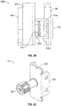
FIG. 2C shows an exemplary locking ear in the system ofFIG. 2A , according to an embodiment of the present disclosure. -
FIG. 2D shows an exemplary locking ear locked onto the rail assembly, according to an embodiment of the present disclosure. -
FIG. 3A shows an exemplary inverse orientation of a computer chassis on a rail assembly, according to an embodiment of the present disclosure. -
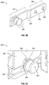
FIG. 3B shows an exemplary locking ear, according to an embodiment of the present disclosure. -
FIG. 3C shows an exemplary locking ear in a rail body, according to an embodiment of the present disclosure. -
FIG. 3D shows an exemplary disassembled view of a locking ear in a rail body, according to an embodiment of the present disclosure. - The present invention is described with reference to the attached figures, where like reference numerals are used throughout the figures to designate similar or equivalent elements. The figures are not drawn to scale, and are provided merely to illustrate the instant invention. Several aspects of the invention are described below with reference to example applications for illustration. It should be understood that numerous specific details, relationships, and methods are set forth to provide a full understanding of the invention. One having ordinary skill in the relevant art, however, will readily recognize that the invention can be practiced without one or more of the specific details, or with other methods. In other instances, well-known structures or operations are not shown in detail to avoid obscuring the invention. The present invention is not limited by the illustrated ordering of acts or events, as some acts may occur in different orders and/or concurrently with other acts or events. Furthermore, not all illustrated acts or events are required to implement a methodology in accordance with the present invention.
- The present disclosure is directed to a rail assembly in a storage rack that includes a rail body, a rail member, and a locking ear. The rail body can engage with front and rear portions of the storage rack, and provide structural support to receive a computer chassis. The rail member can have a slot configured for slidably receiving pins along the side edge of a computer chassis. These pins provide additional structural support along the length of the computer chassis to stabilize the computer chassis during shipping or movement of the storage rack. Lastly, the present disclosure provides for two alternative locking ears. A first locking ear can allow the computer chassis to be loaded into the storage rack with a front end of the computer chassis accessible to a user, and the second locking ear can provide for an inverse orientation such that a rear end of the computer chassis is accessible to a user.
- An exemplary rail kit assembly can also provide flexibility for how chassis are loaded into the storage rack. An exemplary rail kit assembly does not require a pre-determined distance from a shipping container.
-
FIG. 1 shows asystem 100 of a chassis loaded in a storage rack, according to the prior art.System 100 can include frontvertical portions 102, rearvertical portions 104,rail bodies 106, acomputing device 108, and lockingears 110. - A storage rack can have front
vertical portions 102 and rearvertical portions 104. Bothvertical portions rail bodies 106 and lockingears 110. AlthoughFIG. 1 shows a single pair ofrail bodies 106, storage racks can provide for a plurality ofrail bodies 106 configured to receive a plurality of computing devices such that the computing devices are stacked on top of each other. As shown inFIG. 1 , arail body 106 can extend between a frontvertical portion 102 and an opposing rearvertical portion 104. Acomputing device 108 can be loaded into the pair ofrail bodies 106. Lockingear 110 can secure thecomputing device 108 in therail bodies 106.System 100 only provides for lockingear 110 to interface with afirst end 107a of thecomputing device 108. Lockingear 110 cannot interface with asecond end 107b of thecomputing device 108 because it would interfere with portions of thevertical posts 104. -
System 100 allows for only a first orientation of loading thecomputing device 108. Thesecond end 107b of thecomputing device 108 must be loaded onto therail bodies 106 first, such that thefirst end 107a of thecomputing device 108 is accessible by a user once thecomputing device 108 has been loaded into the storage rack. Therefore,system 100 does not provide an orientation where thesecond end 107b of thecomputing device 108 is accessible once thecomputing device 108 has been loaded. - After loading the
computing device 108, a lockingear 110 can be attached to the frontvertical portions 102 and therail body 106. This lockingear 110 therefore locks a horizontal position of thecomputing device 108 with therail bodies 106 and the frontvertical portions 102. However,system 100 does not provide any stability mechanism for thesecond end 107b of the computing device. Therefore, thesecond end 107b can be floating and unattached to therail bodies 106 or rearvertical portions 104. When multiple computer devices are loaded on top of each other, the computer devices might press against each other during rack movement. This can damage the devices themselves or the sensitive components housed in the computer devices. - In response to the limitations of storage racks, the present disclosure provides a rail kit assembly which provides for different loading orientations and better stabilization of the computing device in the storage rack.
FIG. 2A shows anexemplary system 200A which provides for a computing device loaded into a storage rack, according to an embodiment of the present disclosure.System 200A can include many components and similar labels tosystem 100 ofFIG. 1 .System 200A can additionally includerail members 212, andpin assemblies 200B. For purposes of the present disclosure,computing device 108 can refer to a computer chassis or any housing which has computer components disposed in the housing. -
Rail members 212 can be attached to therail bodies 106.Rail members 212 can be in a 'c' shape with a slot extending along a horizontal length of therail member 212. Referring momentarily toFIG. 2B , an exemplary side-perspective of apin assembly 200B is shown.Rail member 212 can includeattachment portions 212a which provide a passage forpins 214 to slide within therail member 212.Attachment portions 212a can be perpendicular torail body 106 and can be set apart at a width substantially similar to a diameter ofpin 214. Pin 214 can therefore fit snuggly withinrail member 212. This snug fit provides stabilization so thatcomputing device 108 cannot move vertically. Additionally,rail member 212 can have alip portion 212b which helps guidepins 214 alongrail member 212. Thelip portion 212b can be attached to an upper orlower attachment portion 212a, and can be sized according to an indented portion ofpin 214. Thelip portion 212b can provide additional stabilization ofcomputing device 108.Pins 214 can slide alongrail member 212 when computingdevice 108 is loaded into or removed from a storage rack. However, the snug fit ofpins 214 intorail member 212 can prevent additional horizontal movement when a user is not movingcomputing device 108 into or out of the storage rack. - Referring back to
FIG. 2A , thepin assemblies 200B can be positioned along aside portion 207c of thecomputing device 108. Although fourpin assemblies 200B are pictured inFIG. 2A , an exemplary embodiment can provide for more orfewer pin assemblies 200B, so long as there is at least onepin assembly 200B towards thesecond end 107b. Therefore,system 200A provides stabilization alongsideportions 207c of thecomputing device 108 such that thecomputing device 108 is held securely within the rail assembly. This can limit damage to thecomputing devices 108 during shipping or movement. -
FIG. 2A shows a first orientation, where afirst end 107a of thecomputing device 108 is adjacent to frontvertical portions 102. This first orientation is enabled by lockingear 110, which fixes a horizontal position of thefirst end 107a of thecomputing device 108 in therail body 106. Referring momentarily toFIG. 2C , lockingear 110 is shown in greater detail to have a facingsurface 222, atab 224, and ascrew 226. Facingsurface 222 can be substantially perpendicular totab 224.FIG. 2D shows a zoomed-inview 200D of lockingear 110 as attached tocomputing device 108 andrail body 106. Facingsurface 222 can be placed adjacent to an end portion ofrail body 106. Screw 226 can couple facingsurface 222 to railbody 106 and frontvertical portions 102 to fix a position of computing device 18.Tab 224 can lie adjacent tocomputing device 108 and can attach tocomputing device 108 for additional stability. Therefore,system 200A can interface with lockingear 110 fromsystem 100 ofFIG. 1 . However,system 200A provides additional stability due to the added support provided byrail members 212 and pins 214 (inFIG. 2B ). -
FIG. 3A shows anexemplary system 300A, where acomputing device 108 can be loaded into a storage rack with asecond end 107b accessible to a user.System 300A includes many components and labels similar tosystem 100 ofFIG. 1 andsystem 200A ofFIG. 2A . Although not shown inFIG. 3A ,system 300A can include therail members 212 andpin assemblies 200B ofFIGs. 2A-2B .System 300A can additionally include a lockingear 300B which enables a second orientation of thecomputing device 108. As shown inFIG. 3B ,system 300A provides an orientation where thesecond end 107b ofcomputing device 108 is adjacent to frontvertical portions 102. This allows thesecond end 107b to be accessible by a user while thecomputing device 108 is loaded into a storage rack. This second orientation can be referred to as an inverse orientation. This orientation is enabled by lockingear 300B, as shown in detail inFIG. 3B . Lockingear 300B can include afirst end 332, asecond end 334, amiddle portion 336, receivingelements 338, and aplunger 340. - The
first end 332 can attach to a computing device. For example, screws (not pictured) can fit through the receivingelements 338 to attach to a computing device. Thesecond end 334 can couple with a rail body via aplunger 340. Theplunger 340 can have anindented portion 342 and alip 344. Theindented portion 342 can fit into an opening or slot in a rail body. Thelip 344 can prevent the plunger from becoming removed from such an opening during jostling of the storage rack. - Locking
ear 300B can further include amiddle portion 336. Themiddle portion 336 can extend at an angle away from afirst end 332, where thefirst end 332 lies adjacent to a computing device. Themiddle portion 336 can therefore extend towards arail body 106. Themiddle portion 336 can extend at a set angle, such that theindented portion 342 of theplunger 340 is in line with thefirst end 332. Such an angle allows the lockingear 300B to couple acomputing device 108 to arail body 106 where thecomputing device 108 can lie adjacent to therail body 106 along a full length of the rail body 106 (pictured inFIG. 3A ). -
FIG. 3C shows a zoomed-in, assembledperspective 300C of the coupling between arail body 106 and aplunger 340. Arail body 106 can include anopening 350 configured to receiveplunger 340. Theplunger 340 can slide into theopening 350 along theindented portion 342. Thelip 344 can prevent theplunger 340 from coming out of theopening 350 unless thecomputing device 108 is removed by a user. Theplunger 340 can be configured to slide intoopening 350 and lock into place once received by a receivingelement 360 of therail body 106. -
FIG. 3D shows a zoomed-out, disassembledperspective 300D of how arail body 106 can couple to aplunger 340. As can be seen inFIG. 3D , theplunger 340 can slide along into anopening 350 of a receivingelement 360 at an end of arail body 106. - Therefore,
FIGs. 3A-3D show asystem 300A which uses alocking ear 300B. The lockingear 300B can allow acomputing device 108 to be loaded into a storage rack in an inverse orientation, where asecond end 107b is adjacent to frontvertical portions 102 of the storage rack. - Altogether, a user can choose whether to use locking
ear 110 fromFIGs. 2A and2C-2D , or lockingear 300B fromFIGs. 3A-3D . A user can decide based on whether the user desires access to afirst end 107a or asecond end 107b of thecomputing device 108, once thecomputing device 108 has been loaded. - The terminology used herein is for the purpose of describing particular examples only and is not intended to be limiting of the invention. As used herein, the singular forms "a," "an," and "the" are intended to include the plural forms as well, unless the context clearly indicates otherwise. Furthermore, to the extent that the terms "including," "includes," "having," "has," "with," or variants thereof, are used in either the detailed description and/or the claims, such terms are intended to be inclusive in a manner similar to the term "comprising."
- Unless otherwise defined, all terms (including technical and scientific terms) used herein have the same meaning as commonly understood by one of ordinary skill in the art to which this invention belongs. Furthermore, terms, such as those defined in commonly used dictionaries, should be interpreted as having a meaning that is consistent with their meaning in the context of the relevant art, and will not be interpreted in an idealized or overly formal sense unless expressly so defined herein.
- Although particular embodiments have been described herein, it will be appreciated that the invention is not limited thereto and that many modifications and additions thereto may be made within the scope of the invention. For example, various combinations of the features of the following dependent claims can be made with the features of the independent claims without departing from the scope of the present invention.
Claims (11)
- A rail assembly for a computing device (108), comprising:a rail body (106);a rail member (212) attached to the rail body (106) and configured with a slot extending horizontally along the rail member (212) for slidably receiving a plurality of pins (200B) disposed along a side surface of the computing device (108); anda locking ear (110 or 300B) configured for fixing a horizontal position of the computing device (108) along the rail member (212), the locking ear (110) configured to support one of a first orientation or a second orientation of the computing device (108).
- The rail assembly of claim 1, wherein the rail member (212) is a C-shaped rail.
- The rail assembly of any one of claims 1-2, wherein the computing device (108) comprises a first end (107a) and a second end (107b).
- The rail assembly of any one of claims 1-3, wherein the locking ear (300B) for the first orientation comprises a facing surface (222) and a tab (224).
- The rail assembly of claim 4, wherein the facing surface (222) is substantially perpendicular to the tab (224).
- The rail assembly of claim 3, wherein the locking ear (300B) for the second orientation comprises a first end (332) configured to attach to the computing device (108) and a second end (334) configured to couple with the rail body (106).
- The rail assembly of claim 6, wherein the second end (334) comprises a plunger (340).
- The rail assembly of claim 7, wherein the plunger (340) comprises a lip (344) and an indented portion (342).
- The rail assembly of claim 7 or claim 8, wherein the locking ear (300B) further comprises a middle portion (336) extending away from the first end (332) at an angle such that the indented portion (342) of the plunger (340) is in line with the first end (332).
- The rail assembly of any one of claims 7-9, wherein the rail body (106) comprises an opening (350) configured to receive the plunger (340).
- A storage rack configured to house a plurality of computing devices (108), comprising:front vertical portions (102);rear vertical portions (104) configured to oppose the front vertical portions (102); andthe rail assembly of any one of claims 1-10, wherein the rail body (106) is configured to engaged with one of the front vertical portions (102) and an opposing one of the rear vertical portions (104).
Applications Claiming Priority (2)
| Application Number | Priority Date | Filing Date | Title |
|---|---|---|---|
| US201862723778P | 2018-08-28 | 2018-08-28 | |
| US16/216,017 US10687438B2 (en) | 2018-08-28 | 2018-12-11 | Rail assembly for storage rack |
Publications (2)
| Publication Number | Publication Date |
|---|---|
| EP3618590A1 true EP3618590A1 (en) | 2020-03-04 |
| EP3618590B1 EP3618590B1 (en) | 2022-05-11 |
Family
ID=66041147
Family Applications (1)
| Application Number | Title | Priority Date | Filing Date |
|---|---|---|---|
| EP19165850.9A Active EP3618590B1 (en) | 2018-08-28 | 2019-03-28 | Rail assembly for storage rack |
Country Status (5)
| Country | Link |
|---|---|
| US (1) | US10687438B2 (en) |
| EP (1) | EP3618590B1 (en) |
| JP (1) | JP6761880B2 (en) |
| CN (1) | CN110868837B (en) |
| TW (1) | TWI717689B (en) |
Families Citing this family (2)
| Publication number | Priority date | Publication date | Assignee | Title |
|---|---|---|---|---|
| TWI751080B (en) | 2021-05-04 | 2021-12-21 | 川湖科技股份有限公司 | Slide rail assembly and slide rail kit thereof |
| TWI828564B (en) | 2023-03-23 | 2024-01-01 | 明泰科技股份有限公司 | Ear stand assembly for easy installation |
Citations (5)
| Publication number | Priority date | Publication date | Assignee | Title |
|---|---|---|---|---|
| US6220456B1 (en) * | 2000-04-19 | 2001-04-24 | Dell Products, L.P. | Method and apparatus for supporting a computer chassis |
| US20030150823A1 (en) * | 2002-02-11 | 2003-08-14 | Dean Ronald P. | Apparatus and method for rackmounting a chassis |
| US20170181312A1 (en) * | 2015-12-22 | 2017-06-22 | Quanta Computer Inc. | Reverse mount apparatus for a rack-mounted systems |
| EP3258755A1 (en) * | 2016-06-16 | 2017-12-20 | King Slide Works Co., Ltd. | Rack system |
| EP3273757A1 (en) * | 2016-07-19 | 2018-01-24 | King Slide Works Co., Ltd. | Slide rail assembly for rack system |
Family Cites Families (15)
| Publication number | Priority date | Publication date | Assignee | Title |
|---|---|---|---|---|
| US6442030B1 (en) * | 2001-04-26 | 2002-08-27 | Central Industrial Supply Company, Inc. | Server system rack drawer with keyboard, flat panel display and electronic switch |
| TW564012U (en) * | 2003-03-28 | 2003-11-21 | Hon Hai Prec Ind Co Ltd | Mounting assembly for a cabinet |
| US7382623B2 (en) * | 2003-06-11 | 2008-06-03 | Dell Products L.P. | Method and system for coupling a chassis to a rail |
| CN201532602U (en) * | 2009-10-14 | 2010-07-21 | 纬创资通股份有限公司 | Electronic device with shock-absorbing function |
| CN102065657B (en) * | 2009-11-16 | 2015-04-01 | 陈为 | Cabinet |
| JP5464582B2 (en) * | 2009-11-25 | 2014-04-09 | 新電元工業株式会社 | Electronics |
| CN102245002A (en) * | 2010-05-11 | 2011-11-16 | 鸿富锦精密工业(深圳)有限公司 | Server rack |
| US9007084B2 (en) * | 2010-06-15 | 2015-04-14 | International Business Machines Corporation | Support structure for installation of a component assembly housed in a rotating, translating carriage chassis |
| CN103096675A (en) * | 2011-10-31 | 2013-05-08 | 鸿富锦精密工业(深圳)有限公司 | Electronic equipment and sliding module thereof |
| MX394007B (en) * | 2014-09-11 | 2025-03-12 | Panduit Corp | ELECTRONIC COMPONENT CABINET. |
| US9578779B2 (en) * | 2015-04-16 | 2017-02-21 | Sandisk Technologies Llc | Front rack cable management system and apparatus |
| CN107801348B (en) * | 2016-09-07 | 2020-08-18 | 川湖科技股份有限公司 | Slide rail assembly and its cable management device |
| CN109413923B (en) * | 2017-08-18 | 2021-07-09 | 联想企业解决方案(新加坡)有限公司 | Rail assembly |
| CN207519020U (en) * | 2017-11-27 | 2018-06-19 | 勤昆科技(昆山)有限公司 | Server cabinet and its sliding rail assembly |
| CN107911988A (en) * | 2017-12-15 | 2018-04-13 | 无锡优耐特能源科技有限公司 | A kind of adjustable cabinet board of depth |
-
2018
- 2018-12-11 US US16/216,017 patent/US10687438B2/en active Active
-
2019
- 2019-02-14 TW TW108104994A patent/TWI717689B/en active
- 2019-02-28 CN CN201910149293.2A patent/CN110868837B/en active Active
- 2019-03-28 EP EP19165850.9A patent/EP3618590B1/en active Active
- 2019-04-16 JP JP2019078167A patent/JP6761880B2/en active Active
Patent Citations (6)
| Publication number | Priority date | Publication date | Assignee | Title |
|---|---|---|---|---|
| US6220456B1 (en) * | 2000-04-19 | 2001-04-24 | Dell Products, L.P. | Method and apparatus for supporting a computer chassis |
| US20030150823A1 (en) * | 2002-02-11 | 2003-08-14 | Dean Ronald P. | Apparatus and method for rackmounting a chassis |
| US20170181312A1 (en) * | 2015-12-22 | 2017-06-22 | Quanta Computer Inc. | Reverse mount apparatus for a rack-mounted systems |
| US10440851B2 (en) * | 2015-12-22 | 2019-10-08 | Quanta Computer Inc. | Reverse mount apparatus for a rack-mounted systems |
| EP3258755A1 (en) * | 2016-06-16 | 2017-12-20 | King Slide Works Co., Ltd. | Rack system |
| EP3273757A1 (en) * | 2016-07-19 | 2018-01-24 | King Slide Works Co., Ltd. | Slide rail assembly for rack system |
Also Published As
| Publication number | Publication date |
|---|---|
| CN110868837B (en) | 2021-02-26 |
| JP6761880B2 (en) | 2020-09-30 |
| TWI717689B (en) | 2021-02-01 |
| CN110868837A (en) | 2020-03-06 |
| US20200077536A1 (en) | 2020-03-05 |
| JP2020035996A (en) | 2020-03-05 |
| US10687438B2 (en) | 2020-06-16 |
| EP3618590B1 (en) | 2022-05-11 |
| TW202010383A (en) | 2020-03-01 |
Similar Documents
| Publication | Publication Date | Title |
|---|---|---|
| US20110290746A1 (en) | Slide assembly | |
| US6726164B1 (en) | Mounting bracket having a tapered plunger latch | |
| US20130056432A1 (en) | Mounting apparatus for slide rail | |
| US8468706B2 (en) | Test device for testing distance between centers of two through holes | |
| US8755178B2 (en) | Frame assembly for detachably fixing an electrical component and electronic device employing same | |
| US10687438B2 (en) | Rail assembly for storage rack | |
| US20110290972A1 (en) | Mounting apparatus for expansion card | |
| US20150195937A1 (en) | Electronic device including retractable bolt member | |
| AU2012290085B2 (en) | User interface mounting module and method to mount a user interface on a UPS | |
| US20060044767A1 (en) | Peripheral component interconnection (PCI) riser card positioning structure of computer server | |
| US7463483B1 (en) | Bracket structure | |
| US11277933B2 (en) | Cable management arm | |
| US20200344911A1 (en) | Middle slide latch | |
| US12174675B2 (en) | Holding devices for computing components | |
| US11128008B2 (en) | Battery module and electronic device | |
| US10524381B1 (en) | Spring mounted slidable lock for rack components | |
| CN109388202B (en) | Fixing frame assembly | |
| CN115226358B (en) | Support frame and data storage equipment cabinet | |
| US20140376999A1 (en) | Expansion card mounting assembly | |
| US11547012B2 (en) | Rail kit strengthening bracket | |
| US12332685B2 (en) | Device stands | |
| US7239512B2 (en) | Computer enclosure incorporating hood fastening structure | |
| US8418985B2 (en) | Electronic device frame and support mechanism utilized thereby | |
| US8320114B2 (en) | Mounting apparatus for data storage device | |
| US20120326579A1 (en) | Computer enclosure with pull tab |
Legal Events
| Date | Code | Title | Description |
|---|---|---|---|
| PUAI | Public reference made under article 153(3) epc to a published international application that has entered the european phase |
Free format text: ORIGINAL CODE: 0009012 |
|
| STAA | Information on the status of an ep patent application or granted ep patent |
Free format text: STATUS: THE APPLICATION HAS BEEN PUBLISHED |
|
| AK | Designated contracting states |
Kind code of ref document: A1 Designated state(s): AL AT BE BG CH CY CZ DE DK EE ES FI FR GB GR HR HU IE IS IT LI LT LU LV MC MK MT NL NO PL PT RO RS SE SI SK SM TR |
|
| AX | Request for extension of the european patent |
Extension state: BA ME |
|
| STAA | Information on the status of an ep patent application or granted ep patent |
Free format text: STATUS: REQUEST FOR EXAMINATION WAS MADE |
|
| 17P | Request for examination filed |
Effective date: 20200621 |
|
| RBV | Designated contracting states (corrected) |
Designated state(s): AL AT BE BG CH CY CZ DE DK EE ES FI FR GB GR HR HU IE IS IT LI LT LU LV MC MK MT NL NO PL PT RO RS SE SI SK SM TR |
|
| GRAP | Despatch of communication of intention to grant a patent |
Free format text: ORIGINAL CODE: EPIDOSNIGR1 |
|
| STAA | Information on the status of an ep patent application or granted ep patent |
Free format text: STATUS: GRANT OF PATENT IS INTENDED |
|
| INTG | Intention to grant announced |
Effective date: 20220202 |
|
| GRAS | Grant fee paid |
Free format text: ORIGINAL CODE: EPIDOSNIGR3 |
|
| GRAA | (expected) grant |
Free format text: ORIGINAL CODE: 0009210 |
|
| STAA | Information on the status of an ep patent application or granted ep patent |
Free format text: STATUS: THE PATENT HAS BEEN GRANTED |
|
| AK | Designated contracting states |
Kind code of ref document: B1 Designated state(s): AL AT BE BG CH CY CZ DE DK EE ES FI FR GB GR HR HU IE IS IT LI LT LU LV MC MK MT NL NO PL PT RO RS SE SI SK SM TR |
|
| REG | Reference to a national code |
Ref country code: GB Ref legal event code: FG4D |
|
| REG | Reference to a national code |
Ref country code: CH Ref legal event code: EP |
|
| REG | Reference to a national code |
Ref country code: AT Ref legal event code: REF Ref document number: 1492623 Country of ref document: AT Kind code of ref document: T Effective date: 20220515 |
|
| REG | Reference to a national code |
Ref country code: DE Ref legal event code: R096 Ref document number: 602019014737 Country of ref document: DE |
|
| REG | Reference to a national code |
Ref country code: IE Ref legal event code: FG4D |
|
| REG | Reference to a national code |
Ref country code: LT Ref legal event code: MG9D |
|
| REG | Reference to a national code |
Ref country code: NL Ref legal event code: MP Effective date: 20220511 |
|
| REG | Reference to a national code |
Ref country code: AT Ref legal event code: MK05 Ref document number: 1492623 Country of ref document: AT Kind code of ref document: T Effective date: 20220511 |
|
| PG25 | Lapsed in a contracting state [announced via postgrant information from national office to epo] |
Ref country code: SE Free format text: LAPSE BECAUSE OF FAILURE TO SUBMIT A TRANSLATION OF THE DESCRIPTION OR TO PAY THE FEE WITHIN THE PRESCRIBED TIME-LIMIT Effective date: 20220511 Ref country code: PT Free format text: LAPSE BECAUSE OF FAILURE TO SUBMIT A TRANSLATION OF THE DESCRIPTION OR TO PAY THE FEE WITHIN THE PRESCRIBED TIME-LIMIT Effective date: 20220912 Ref country code: NO Free format text: LAPSE BECAUSE OF FAILURE TO SUBMIT A TRANSLATION OF THE DESCRIPTION OR TO PAY THE FEE WITHIN THE PRESCRIBED TIME-LIMIT Effective date: 20220811 Ref country code: NL Free format text: LAPSE BECAUSE OF FAILURE TO SUBMIT A TRANSLATION OF THE DESCRIPTION OR TO PAY THE FEE WITHIN THE PRESCRIBED TIME-LIMIT Effective date: 20220511 Ref country code: LT Free format text: LAPSE BECAUSE OF FAILURE TO SUBMIT A TRANSLATION OF THE DESCRIPTION OR TO PAY THE FEE WITHIN THE PRESCRIBED TIME-LIMIT Effective date: 20220511 Ref country code: HR Free format text: LAPSE BECAUSE OF FAILURE TO SUBMIT A TRANSLATION OF THE DESCRIPTION OR TO PAY THE FEE WITHIN THE PRESCRIBED TIME-LIMIT Effective date: 20220511 Ref country code: GR Free format text: LAPSE BECAUSE OF FAILURE TO SUBMIT A TRANSLATION OF THE DESCRIPTION OR TO PAY THE FEE WITHIN THE PRESCRIBED TIME-LIMIT Effective date: 20220812 Ref country code: FI Free format text: LAPSE BECAUSE OF FAILURE TO SUBMIT A TRANSLATION OF THE DESCRIPTION OR TO PAY THE FEE WITHIN THE PRESCRIBED TIME-LIMIT Effective date: 20220511 Ref country code: ES Free format text: LAPSE BECAUSE OF FAILURE TO SUBMIT A TRANSLATION OF THE DESCRIPTION OR TO PAY THE FEE WITHIN THE PRESCRIBED TIME-LIMIT Effective date: 20220511 Ref country code: BG Free format text: LAPSE BECAUSE OF FAILURE TO SUBMIT A TRANSLATION OF THE DESCRIPTION OR TO PAY THE FEE WITHIN THE PRESCRIBED TIME-LIMIT Effective date: 20220811 Ref country code: AT Free format text: LAPSE BECAUSE OF FAILURE TO SUBMIT A TRANSLATION OF THE DESCRIPTION OR TO PAY THE FEE WITHIN THE PRESCRIBED TIME-LIMIT Effective date: 20220511 |
|
| PG25 | Lapsed in a contracting state [announced via postgrant information from national office to epo] |
Ref country code: RS Free format text: LAPSE BECAUSE OF FAILURE TO SUBMIT A TRANSLATION OF THE DESCRIPTION OR TO PAY THE FEE WITHIN THE PRESCRIBED TIME-LIMIT Effective date: 20220511 Ref country code: PL Free format text: LAPSE BECAUSE OF FAILURE TO SUBMIT A TRANSLATION OF THE DESCRIPTION OR TO PAY THE FEE WITHIN THE PRESCRIBED TIME-LIMIT Effective date: 20220511 Ref country code: LV Free format text: LAPSE BECAUSE OF FAILURE TO SUBMIT A TRANSLATION OF THE DESCRIPTION OR TO PAY THE FEE WITHIN THE PRESCRIBED TIME-LIMIT Effective date: 20220511 Ref country code: IS Free format text: LAPSE BECAUSE OF FAILURE TO SUBMIT A TRANSLATION OF THE DESCRIPTION OR TO PAY THE FEE WITHIN THE PRESCRIBED TIME-LIMIT Effective date: 20220911 |
|
| PG25 | Lapsed in a contracting state [announced via postgrant information from national office to epo] |
Ref country code: SM Free format text: LAPSE BECAUSE OF FAILURE TO SUBMIT A TRANSLATION OF THE DESCRIPTION OR TO PAY THE FEE WITHIN THE PRESCRIBED TIME-LIMIT Effective date: 20220511 Ref country code: SK Free format text: LAPSE BECAUSE OF FAILURE TO SUBMIT A TRANSLATION OF THE DESCRIPTION OR TO PAY THE FEE WITHIN THE PRESCRIBED TIME-LIMIT Effective date: 20220511 Ref country code: RO Free format text: LAPSE BECAUSE OF FAILURE TO SUBMIT A TRANSLATION OF THE DESCRIPTION OR TO PAY THE FEE WITHIN THE PRESCRIBED TIME-LIMIT Effective date: 20220511 Ref country code: EE Free format text: LAPSE BECAUSE OF FAILURE TO SUBMIT A TRANSLATION OF THE DESCRIPTION OR TO PAY THE FEE WITHIN THE PRESCRIBED TIME-LIMIT Effective date: 20220511 Ref country code: DK Free format text: LAPSE BECAUSE OF FAILURE TO SUBMIT A TRANSLATION OF THE DESCRIPTION OR TO PAY THE FEE WITHIN THE PRESCRIBED TIME-LIMIT Effective date: 20220511 Ref country code: CZ Free format text: LAPSE BECAUSE OF FAILURE TO SUBMIT A TRANSLATION OF THE DESCRIPTION OR TO PAY THE FEE WITHIN THE PRESCRIBED TIME-LIMIT Effective date: 20220511 |
|
| REG | Reference to a national code |
Ref country code: DE Ref legal event code: R097 Ref document number: 602019014737 Country of ref document: DE |
|
| PLBE | No opposition filed within time limit |
Free format text: ORIGINAL CODE: 0009261 |
|
| STAA | Information on the status of an ep patent application or granted ep patent |
Free format text: STATUS: NO OPPOSITION FILED WITHIN TIME LIMIT |
|
| PG25 | Lapsed in a contracting state [announced via postgrant information from national office to epo] |
Ref country code: AL Free format text: LAPSE BECAUSE OF FAILURE TO SUBMIT A TRANSLATION OF THE DESCRIPTION OR TO PAY THE FEE WITHIN THE PRESCRIBED TIME-LIMIT Effective date: 20220511 |
|
| 26N | No opposition filed |
Effective date: 20230214 |
|
| PG25 | Lapsed in a contracting state [announced via postgrant information from national office to epo] |
Ref country code: SI Free format text: LAPSE BECAUSE OF FAILURE TO SUBMIT A TRANSLATION OF THE DESCRIPTION OR TO PAY THE FEE WITHIN THE PRESCRIBED TIME-LIMIT Effective date: 20220511 |
|
| PG25 | Lapsed in a contracting state [announced via postgrant information from national office to epo] |
Ref country code: MC Free format text: LAPSE BECAUSE OF FAILURE TO SUBMIT A TRANSLATION OF THE DESCRIPTION OR TO PAY THE FEE WITHIN THE PRESCRIBED TIME-LIMIT Effective date: 20220511 |
|
| REG | Reference to a national code |
Ref country code: CH Ref legal event code: PL |
|
| REG | Reference to a national code |
Ref country code: BE Ref legal event code: MM Effective date: 20230331 |
|
| PG25 | Lapsed in a contracting state [announced via postgrant information from national office to epo] |
Ref country code: LU Free format text: LAPSE BECAUSE OF NON-PAYMENT OF DUE FEES Effective date: 20230328 |
|
| REG | Reference to a national code |
Ref country code: IE Ref legal event code: MM4A |
|
| PG25 | Lapsed in a contracting state [announced via postgrant information from national office to epo] |
Ref country code: LI Free format text: LAPSE BECAUSE OF NON-PAYMENT OF DUE FEES Effective date: 20230331 Ref country code: IT Free format text: LAPSE BECAUSE OF FAILURE TO SUBMIT A TRANSLATION OF THE DESCRIPTION OR TO PAY THE FEE WITHIN THE PRESCRIBED TIME-LIMIT Effective date: 20220511 Ref country code: IE Free format text: LAPSE BECAUSE OF NON-PAYMENT OF DUE FEES Effective date: 20230328 Ref country code: CH Free format text: LAPSE BECAUSE OF NON-PAYMENT OF DUE FEES Effective date: 20230331 |
|
| PG25 | Lapsed in a contracting state [announced via postgrant information from national office to epo] |
Ref country code: BE Free format text: LAPSE BECAUSE OF NON-PAYMENT OF DUE FEES Effective date: 20230331 |
|
| PG25 | Lapsed in a contracting state [announced via postgrant information from national office to epo] |
Ref country code: BG Free format text: LAPSE BECAUSE OF FAILURE TO SUBMIT A TRANSLATION OF THE DESCRIPTION OR TO PAY THE FEE WITHIN THE PRESCRIBED TIME-LIMIT Effective date: 20220511 |
|
| PG25 | Lapsed in a contracting state [announced via postgrant information from national office to epo] |
Ref country code: BG Free format text: LAPSE BECAUSE OF FAILURE TO SUBMIT A TRANSLATION OF THE DESCRIPTION OR TO PAY THE FEE WITHIN THE PRESCRIBED TIME-LIMIT Effective date: 20220511 |
|
| PG25 | Lapsed in a contracting state [announced via postgrant information from national office to epo] |
Ref country code: CY Free format text: LAPSE BECAUSE OF FAILURE TO SUBMIT A TRANSLATION OF THE DESCRIPTION OR TO PAY THE FEE WITHIN THE PRESCRIBED TIME-LIMIT; INVALID AB INITIO Effective date: 20190328 |
|
| PG25 | Lapsed in a contracting state [announced via postgrant information from national office to epo] |
Ref country code: HU Free format text: LAPSE BECAUSE OF FAILURE TO SUBMIT A TRANSLATION OF THE DESCRIPTION OR TO PAY THE FEE WITHIN THE PRESCRIBED TIME-LIMIT; INVALID AB INITIO Effective date: 20190328 |
|
| PG25 | Lapsed in a contracting state [announced via postgrant information from national office to epo] |
Ref country code: TR Free format text: LAPSE BECAUSE OF FAILURE TO SUBMIT A TRANSLATION OF THE DESCRIPTION OR TO PAY THE FEE WITHIN THE PRESCRIBED TIME-LIMIT Effective date: 20220511 |
|
| PGFP | Annual fee paid to national office [announced via postgrant information from national office to epo] |
Ref country code: GB Payment date: 20260209 Year of fee payment: 8 |
|
| PGFP | Annual fee paid to national office [announced via postgrant information from national office to epo] |
Ref country code: DE Payment date: 20260204 Year of fee payment: 8 |
|
| PGFP | Annual fee paid to national office [announced via postgrant information from national office to epo] |
Ref country code: FR Payment date: 20260209 Year of fee payment: 8 |