EP3618516A1 - Frame formats for distributed mimo - Google Patents
Frame formats for distributed mimo Download PDFInfo
- Publication number
- EP3618516A1 EP3618516A1 EP19193826.5A EP19193826A EP3618516A1 EP 3618516 A1 EP3618516 A1 EP 3618516A1 EP 19193826 A EP19193826 A EP 19193826A EP 3618516 A1 EP3618516 A1 EP 3618516A1
- Authority
- EP
- European Patent Office
- Prior art keywords
- access point
- slave
- time period
- station device
- master
- Prior art date
- Legal status (The legal status is an assumption and is not a legal conclusion. Google has not performed a legal analysis and makes no representation as to the accuracy of the status listed.)
- Granted
Links
Images







Classifications
-
- H—ELECTRICITY
- H04—ELECTRIC COMMUNICATION TECHNIQUE
- H04W—WIRELESS COMMUNICATION NETWORKS
- H04W56/00—Synchronisation arrangements
- H04W56/001—Synchronization between nodes
- H04W56/0015—Synchronization between nodes one node acting as a reference for the others
-
- H—ELECTRICITY
- H04—ELECTRIC COMMUNICATION TECHNIQUE
- H04W—WIRELESS COMMUNICATION NETWORKS
- H04W56/00—Synchronisation arrangements
- H04W56/001—Synchronization between nodes
-
- H—ELECTRICITY
- H04—ELECTRIC COMMUNICATION TECHNIQUE
- H04B—TRANSMISSION
- H04B7/00—Radio transmission systems, i.e. using radiation field
- H04B7/02—Diversity systems; Multi-antenna system, i.e. transmission or reception using multiple antennas
- H04B7/022—Site diversity; Macro-diversity
- H04B7/024—Co-operative use of antennas of several sites, e.g. in co-ordinated multipoint or co-operative multiple-input multiple-output [MIMO] systems
-
- H—ELECTRICITY
- H04—ELECTRIC COMMUNICATION TECHNIQUE
- H04B—TRANSMISSION
- H04B7/00—Radio transmission systems, i.e. using radiation field
- H04B7/02—Diversity systems; Multi-antenna system, i.e. transmission or reception using multiple antennas
- H04B7/04—Diversity systems; Multi-antenna system, i.e. transmission or reception using multiple antennas using two or more spaced independent antennas
- H04B7/0413—MIMO systems
-
- H—ELECTRICITY
- H04—ELECTRIC COMMUNICATION TECHNIQUE
- H04B—TRANSMISSION
- H04B7/00—Radio transmission systems, i.e. using radiation field
- H04B7/02—Diversity systems; Multi-antenna system, i.e. transmission or reception using multiple antennas
- H04B7/04—Diversity systems; Multi-antenna system, i.e. transmission or reception using multiple antennas using two or more spaced independent antennas
- H04B7/0413—MIMO systems
- H04B7/0452—Multi-user MIMO systems
-
- H—ELECTRICITY
- H04—ELECTRIC COMMUNICATION TECHNIQUE
- H04B—TRANSMISSION
- H04B7/00—Radio transmission systems, i.e. using radiation field
- H04B7/02—Diversity systems; Multi-antenna system, i.e. transmission or reception using multiple antennas
- H04B7/04—Diversity systems; Multi-antenna system, i.e. transmission or reception using multiple antennas using two or more spaced independent antennas
- H04B7/06—Diversity systems; Multi-antenna system, i.e. transmission or reception using multiple antennas using two or more spaced independent antennas at the transmitting station
- H04B7/0613—Diversity systems; Multi-antenna system, i.e. transmission or reception using multiple antennas using two or more spaced independent antennas at the transmitting station using simultaneous transmission
- H04B7/0615—Diversity systems; Multi-antenna system, i.e. transmission or reception using multiple antennas using two or more spaced independent antennas at the transmitting station using simultaneous transmission of weighted versions of same signal
- H04B7/0617—Diversity systems; Multi-antenna system, i.e. transmission or reception using multiple antennas using two or more spaced independent antennas at the transmitting station using simultaneous transmission of weighted versions of same signal for beam forming
-
- H—ELECTRICITY
- H04—ELECTRIC COMMUNICATION TECHNIQUE
- H04B—TRANSMISSION
- H04B7/00—Radio transmission systems, i.e. using radiation field
- H04B7/02—Diversity systems; Multi-antenna system, i.e. transmission or reception using multiple antennas
- H04B7/04—Diversity systems; Multi-antenna system, i.e. transmission or reception using multiple antennas using two or more spaced independent antennas
- H04B7/08—Diversity systems; Multi-antenna system, i.e. transmission or reception using multiple antennas using two or more spaced independent antennas at the receiving station
- H04B7/0837—Diversity systems; Multi-antenna system, i.e. transmission or reception using multiple antennas using two or more spaced independent antennas at the receiving station using pre-detection combining
- H04B7/0842—Weighted combining
- H04B7/086—Weighted combining using weights depending on external parameters, e.g. direction of arrival [DOA], predetermined weights or beamforming
-
- H—ELECTRICITY
- H04—ELECTRIC COMMUNICATION TECHNIQUE
- H04W—WIRELESS COMMUNICATION NETWORKS
- H04W72/00—Local resource management
- H04W72/04—Wireless resource allocation
- H04W72/044—Wireless resource allocation based on the type of the allocated resource
- H04W72/0446—Resources in time domain, e.g. slots or frames
-
- H—ELECTRICITY
- H04—ELECTRIC COMMUNICATION TECHNIQUE
- H04W—WIRELESS COMMUNICATION NETWORKS
- H04W84/00—Network topologies
- H04W84/02—Hierarchically pre-organised networks, e.g. paging networks, cellular networks, WLAN [Wireless Local Area Network] or WLL [Wireless Local Loop]
- H04W84/10—Small scale networks; Flat hierarchical networks
- H04W84/12—WLAN [Wireless Local Area Networks]
-
- H—ELECTRICITY
- H04—ELECTRIC COMMUNICATION TECHNIQUE
- H04W—WIRELESS COMMUNICATION NETWORKS
- H04W92/00—Interfaces specially adapted for wireless communication networks
- H04W92/16—Interfaces between hierarchically similar devices
- H04W92/20—Interfaces between hierarchically similar devices between access points
Definitions
- This disclosure generally relates to systems and methods for providing a joint transmission by a group of distributed access points, including but not limited to frame formats of a joint transmission for sounding and steering.
- Wireless communication can operate in accordance with various standards such as IEEE 802.11 x, Bluetooth, global system for mobile communications (GSM), code division multiple access (CDMA). As higher data throughput and other changes develop, newer standards are constantly being developed for adoption, such as a progression from IEEE 802.1 In to IEEE 802.11ac.
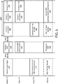
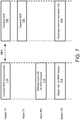
- the method includes transmitting, during a first time period, by a master access point to a slave access point, information for a joint transmission by the master access point and the slave access point. In some embodiments, the method includes estimating, by the slave access point, synchronization information for the joint transmission, according to the information for the joint transmission. In some embodiments, the method includes transmitting, during a second time period after the first time period, by the master access point, a portion of a null data packet to a station device.
- MIMO multiple-input multiple-output
- the method includes transmitting, during the second time period, by the slave access point, the portion of the null data packet to the station device, based on the synchronization information for the joint transmission. In some embodiments, the method includes determining, by the station device, steering information for the MIMO communication, according to the null data packet.
- estimating, by the slave access point, the synchronization information includes estimating, by the slave access point, a carrier frequency offset or a sampling frequency offset with respect to the master access point.
- the method includes transmitting, during a third time period before the first time period, by the master access point, a slave trigger frame to the slave access point.
- the method includes estimating, by the slave access point, additional synchronization information for a null data packet announcement, according to the slave trigger frame.
- the method includes transmitting, during a fourth time period between the third time period and the first time period, by the master access point, the null data packet announcement to the station device.
- the method includes transmitting, during the fourth time period, by the slave access point, the null data packet announcement to the station device. In some embodiments, the method includes preparing, by the station device, for the null data packet, in response to receiving the null data packet announcement.
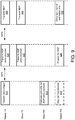
- transmitting, during the first time period, by the master access point to the slave access point, the information for the joint transmission includes transmitting, by the master access point to the slave access point, the information for the joint transmission in a preamble of the null data packet. In some embodiments, transmitting, during the first time period, by the master access point to the slave access point, the information for the joint transmission, includes transmitting, by the master access point to the slave access point, the information for the joint transmission in a null data packet announcement. In some embodiments, the method further includes preparing, by the station device, for the null data packet, in response to the station device receiving the null data packet announcement.
- the method further includes transmitting, during a third time period between the first time period and the second time period, by the master access point, a training field to the station device. In some embodiments, the method further includes transmitting, during the third time period, by the slave access point, the training field to the station device. In some embodiments, the method includes adjusting, by the station device, a gain setting to receive the portion of the null data packet, according to the training field.
- the first access point includes a transceiver and a soundings controller.
- the soundings controller is configured to cause, during a first time period, the transceiver to transmit, to a second access point, information for a joint transmission by the first access point and the second access point.
- the information for the joint transmission allows the second access point to estimate synchronization information for the joint transmission.
- the soundings controller is configured to cause, during a second time period after the first time period, the transceiver to transmit a portion of a null data packet to a station device, based on the synchronization information for the joint transmission.
- the second access point transmits the portion of the null data packet to the station device.
- the joint transmission of the portion of the null data packet by the first access point and the second access point allows the station device to determine steering information for the MIMO communication.
- the soundings controller is configured to cause the transceiver to transmit the portion of the null data packet in a training field. In some embodiments, the soundings controller is further configured to cause the transceiver to transmit, during a third time period before the first time period, a slave trigger frame to the second access point. In some embodiments, the slave trigger frame allows the second access point to estimate additional synchronization information for a null data packet announcement. In some embodiments, the soundings controller is further configured to cause the transceiver to transmit, during a fourth time period between the third time period and the first time period, the null data packet announcement to the station device, while the second access point transmits the null data packet announcement to the station device during the fourth time period according to the synchronization information.
- the null data packet announcement transmitted by the first access point and the second access point allows the station device to prepare for the null data packet.
- the soundings controller is further configured to cause the transceiver to transmit the information for the joint transmission in a preamble of the null data packet.
- the soundings controller is further configured to cause the transceiver to transmit the information for the joint transmission in a null data packet announcement.
- the null data packet announcement allows the station device to prepare for the null data packet.
- the soundings controller is further configured to cause the transceiver to transmit, during a third time period between the first time period and the second time period, a training field to the station device, while the second access point transmits the training field to the station device during the third time period.
- the training field transmitted by the first access point and the second access point allows the station device to adjust a gain setting to receive the portion of the null data packet.
- the soundings controller is further configured to cause the transceiver to transmit, during a third time period between the first time period and the second time period, a null data packet announcement to the station device, while the second access point transmits the null data packet announcement to the station device during the third time period according to the synchronization information.
- the null data packet announcement transmitted by the first access point and the second access point allows the station device to prepare for the null data packet.
- the information for the joint transmission includes two or more long training field (LTF) symbol groups that are separated by at least a symbol.
- the second time period is immediately after the first time period.
- the access point includes a transceiver and a soundings controller.
- the soundings controller is configured to cause the transceiver to receive, during a first time period, from another access point, information for a joint transmission by the access point and the another access point.
- the soundings controller is configured to estimate synchronization information for the joint transmission, according to the information for the joint transmission.
- the soundings controller is configured to cause the transceiver to transmit, during a second time period after the first time period, a portion of a null data packet to a station device according to the synchronization information, while the another access point transmits the portion of the null data packet to the station device during the second time period.
- the portion of the null data packet transmitted by the access point and the another access point allows the station device to determine steering information for the MIMO communication.
- the soundings controller is configured to cause the transceiver to transmit the portion of the null data packet in a training field. In some embodiments, the soundings controller is configured to estimate the synchronization information for the joint transmission by estimating a carrier frequency offset, a sampling frequency offset, a first reference value for a common phase offset, or a second reference value for a timing offset with respect to the another access point.
- the soundings controller is further configured to cause the transceiver to receive, during a third time period before the first time period, from the another access point, a slave trigger frame. In some embodiments, the soundings controller is further configured to estimate additional synchronization information for a null data packet announcement, according to the slave trigger frame. In some embodiments, the soundings controller is further configured to cause the transceiver to transmit, during a fourth time period between the third time period and the first time period, the null data packet announcement to the station device, while the another access point transmits the null data packet announcement to the station device during the fourth time period according to the synchronization information.
- the null data packet announcement transmitted by the access point and the another access point allows the station device to prepare for the null data packet.
- the soundings controller is configured to cause the transceiver to receive the information for the joint transmission in a preamble of the null data packet.
- the soundings controller is configured to cause the transceiver to receive the information for the joint transmission in a null data packet announcement.
- the null data packet announcement allows the station device to prepare for the null data packet.
- the soundings controller is configured to cause the transceiver to transmit, during a third time period between the first time period and the second time period, a training field to the station device, while the another access point transmits the training field to the station device during the third time period.
- the training field transmitted by the access point and the another access point allows the station device to adjust a gain setting to receive the portion of the null data packet.
- the soundings controller is configured to disable the transceiver during a third time period between the first time period and the second time period for a short interframe space. In some embodiments, the soundings controller is configured to cause the transceiver to transmit, during a third time period between the first time period and the second time period, a null data packet announcement to the station device, while the another access point transmits the null data packet announcement to the station device during the third time period according to the synchronization information. In some embodiments, the null data packet announcement transmitted by the access point and the another access point allows the station device to prepare for the null data packet. In some embodiments, the second time period is immediately after the first time period.
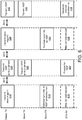
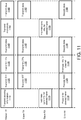
- the method includes transmitting, during a first time period, by a master access point to a slave access point, information for a joint transmission by the master access point and the slave access point. In some embodiments, the method includes causing, by the slave access point, the slave access point to estimate synchronization information for the joint transmission, according to the information for the joint transmission. In some embodiments, the method includes transmitting, during a second time period after the first time period, by the master access point, a portion of a steered frame to a station device.
- MIMO multiple-input multiple-output
- the method includes transmitting, during the second time period, by the slave access point, the portion of the steered frame to the station device, based on the synchronization information for the joint transmission. In some embodiments, the method includes decoding, by the station device, the portion of the steered frame transmitted by the master access point and the slave access point to obtain content data in the portion of the steered frame.
- estimating, by the slave access point, the synchronization information includes estimating, by the slave access point, a carrier frequency offset or a sampling frequency offset with respect to the master access point.
- the information for the joint transmission is transmitted in a slave trigger frame during the first time period.
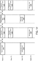
- the steered frame transmitted by the master access point includes a mid-amble.
- the method includes bypassing, by the slave access point, a transmission, while the master access point transmits the mid-amble of the steered frame.
- the steered frame transmitted by the master access point includes a mid-amble.
- the method further includes resynchronizing, by the slave access point, for another joint transmission of another portion of the steered frame by the master access point and the slave access point, according to the mid-amble.
- the method includes bypassing, during a third time period between the first time period and the second time period, by the master access point, a transmission for a short interframe space. In some embodiments, the method includes transmitting, during a third time period between the first time period and the second time period, by the master access point, a training field to the station device. In some embodiments, the method includes transmitting, during the third time period, by the slave access point, the training field to the station device. In some embodiments, the method includes adjusting, by the station device, a gain setting to receive the portion of the steered frame, according to the training field.
- the method includes transmitting, during a third time period after the first time period and the second time period, by the master access point to the slave access point, a null data packet. In some embodiments, the method includes resynchronizing, during the third time period, by the slave access point, for another joint transmission of another steered frame by the master access point and the slave access point. In some embodiments, the method includes transmitting, during a fourth time period after the third time period, by the master access point, the another steered frame to the station device. In some embodiments, the method includes transmitting, during the fourth time period, by the slave access point, the another steered frame to the station device.
- the method includes decoding, by the station device, the another steered frame transmitted by the master access point and the slave access point to obtain additional content data in the another steered frame. In some embodiments, the method includes transmitting, during a fifth time period between the second time period and the third time period, by the station device to the master access point and the slave access point, an acknowledgement frame. In some embodiments, the method includes scheduling, by the master access point and the slave access point, the another joint transmission of the another steered frame, in response to the acknowledgement frame.
- the first access point includes a transceiver and a steering controller.
- the steering controller is configured to cause the transceiver to transmit, during a first time period, to a second access point, information for a joint transmission by the first access point and the second access point.
- the information for the joint transmission allows the second access point to estimate synchronization information for the joint transmission.
- the steering controller is configured to cause the transceiver to transmit, during a second time period after the first time period, a portion of a steered frame to a station device, while the second access point transmits the portion of the steered frame to the station device according to the synchronization information.
- the joint transmission of the portion of the steered frame by the first access point and the second access point allows the station device to receive the portion of the steered frame and decode the portion of the steered frame to obtain content data in the portion of the steered frame.
- the second time period is immediately after the first time period.
- the information for the joint transmission is transmitted in a slave trigger frame during the first time period.
- the steered frame transmitted by the first access point includes a mid-amble.
- the second access point is configured to bypass a transmission, while the first access point transmits the mid-amble of the steered frame.
- the steered frame transmitted by the first access point includes a mid-amble.
- the mid-amble allows the second access point to resynchronize for another joint transmission of another portion of the steered frame by the first access point and the second access point.
- the mid-amble allows the second access point to transition, during the transmission of the mid-amble by the first access point, from a transmit mode to a receive mode and transition back to the transmit mode for the another joint transmission of the another portion of the steered frame by the first access point and the second access point.
- the steering controller is configured to cause the transceiver to bypass, during a third time period between the first time period and the second time period, a transmission for a short interframe space. In some embodiments, the steering controller is configured to cause the transceiver to transmit, during the second time period, a training field to the station device, while the second access point transmits the training field to the station device during the second time period. In some embodiments, the training field transmitted by the first access point and the second access point allows the station device to adjust a gain setting to receive the portion of the steered frame.
- the steering controller is configured to cause the transceiver to transmit, during a third time period after the first time period and the second time period, a null data packet to the second access point.
- the null data packet allows the second access point to resynchronize for another joint transmission of another steered frame by the first access point and the second access point.
- the steering controller is configured to cause the transceiver to transmit, during a fourth time period after the third time period, the another steered frame to the station device, while the second access point transmits the another steered frame to the station device during the fourth time period after the resynchronizing.
- the another steered frame transmitted by the first access point and the second access point allows the station device to receive the another steered frame and decode the another steered frame to obtain additional content data in the another steered frame.
- the steering controller is configured to cause the transceiver to receive, during a fifth time period between the second time period and the third time period, from the station device an acknowledgement frame.
- the steering controller is configured to schedule the another joint transmission of the another steered frame, in response to the acknowledgement frame.
- the steering controller is configured to cause the transceiver to transmit a unique pilot sequence associated with the first access point to enable the station device to estimate additional synchronization information, and receive the additional synchronization information as a feedback.
- the access point includes a transceiver and a steering controller.
- the steering controller is configured to cause the transceiver to receive, during a first time period, from another access point, information for a joint transmission by the access point and the another access point.
- the steering controller is configured to estimate synchronization information for the joint transmission, according to the information for the joint transmission.
- the steering controller is configured to cause the transceiver to transmit, during a second time period after the first time period, a portion of a steered frame to a station device according to the synchronization information, while the another access point transmits the portion of the steered frame to the station device during the second time period.
- the portion of the steered frame transmitted by the access point and the another access point allows the station device to receive the portion of the steered frame and decode the portion of the steered frame to obtain content data in the portion of the steered frame.
- the steering controller is configured to estimate the synchronization information for the joint transmission by estimating a carrier frequency offset, a sampling frequency offset, a first reference value for a common phase offset, or a second reference value for a timing offset with respect to the another access point.
- the steering controller is configured to cause the transceiver to receive, during the first time period, from the another access point, the information for the joint transmission in a slave trigger frame.
- the second time period is immediately after the first time period.
- the steering controller is configured to determine the synchronization information according to a change in a phase offset or a timing offset between a sounding sequence and a steering sequence.
- the steered frame transmitted by the another access point includes a mid-amble.
- the steering controller is configured to cause the transceiver to bypass a transmission, while the another access point transmits the mid-amble of the steered frame.
- the steering controller is configured to, during the transmission of the mid-amble by the another access point, resynchronize for another joint transmission of another portion of the steered frame by the access point and the another access point and transition, from a transmit mode to a receive mode and transition back to the transmit mode for the another joint transmission of the another portion of the steered frame by the access point and the another access point.
- the steering controller is configured to cause the transceiver to transmit, during the second time period, a training field to the station device, while the another access point transmits the training field to the station device during the second time period.
- the training field transmitted by the access point and the another access point allows the station device to adjust a gain setting to receive the portion of the steered frame.
- the steering controller is configured to cause the transceiver to receive, during a third time period after the first time period and the second time period, a null data packet from the another access point.
- the null data packet allows the access point to resynchronize for another joint transmission of another steered frame by the access point and the another access point.
- the steering controller is configured to cause the transceiver to transmit, during a fourth time period after the third time period, the another steered frame to the station device after the resynchronizing, while the another access point transmits the another steered frame to the station device during the fourth time period.
- the another steered frame transmitted by the access point and the another access point allows the station device to receive the another steered frame and decode the another steered frame to obtain additional content data in the another steered frame.
- the steering controller is configured to cause the transceiver to receive, during a fifth time period between the second time period and the third time period, from the station device an acknowledgement frame.
- the steering controller is configured to cause the transceiver to transmit a unique pilot sequence associated with the access point to enable the station device to estimate additional synchronization information, and receive the additional synchronization information as a feedback.
- the steered frame transmitted by the another access point includes a mid-amble.
- the steering controller is configured to cause the transceiver to bypass a transmission, while the another access point transmits the mid-amble of the steered frame.
- the steering controller is configured to cause the transceiver to resynchronize for another joint transmission of another portion of the steered frame by the access point and the another access point according to the mid-amble.
- the steering controller is configured to cause the transceiver to bypass, during a third time period between the first time period and the second time period, a transmission for a short interframe space. In some embodiments, the steering controller is configured to cause the transceiver to transmit, during a third time period between the first time period and the second time period, a training field to the station device, while the another access point transmits the training field to the station device during the third time period. In some embodiments, the training field transmitted by the access point and the another access point allows the station device to adjust a gain setting to receive the portion of the steered frame.
- the steering controller is configured to schedule the another joint transmission of the another steered frame, in response to the acknowledgement frame.
- MIMO multiple-input multiple-output
- causing the slave access point to estimate the synchronization information includes causing the slave access point to estimate a carrier frequency offset or a sampling frequency offset with respect to the master access point.
- the method further comprises: transmitting, during a third time period between the first time period and the second time period, a null data packet announcement to the station device, while the slave access point transmits the null data packet announcement to the station device during the third time period according to the synchronization information, the null data packet announcement transmitted by the master access point and the slave access point allowing the station device to prepare for the null data packet.
- the second time period is immediately after the first time period.
- a first access point for a multiple-input multiple-output (MIMO) communication comprising:
- the soundings controller is further configured to cause the transceiver to:
- the soundings controller is further configured to cause the transceiver to transmit the information for the joint transmission in a preamble of the null data packet.
- the soundings controller is further configured to cause the transceiver to transmit the information for the joint transmission in a null data packet announcement, the null data packet announcement allowing the station device to prepare for the null data packet.
- the soundings controller is further configured to cause the transceiver to transmit, during a third time period between the first time period and the second time period, a training field to the station device, while the second access point transmits the training field to the station device during the third time period, the training field transmitted by the first access point and the second access point allowing the station device to adjust a gain setting to receive the portion of the null data packet.
- the soundings controller is further configured to cause the transceiver to: transmit, during a third time period between the first time period and the second time period, a null data packet announcement to the station device, while the second access point transmits the null data packet announcement to the station device during the third time period according to the synchronization information, the null data packet announcement transmitted by the first access point and the second access point allowing the station device to prepare for the null data packet.
- the information for the joint transmission includes two or more long training field (LTF) symbol groups that are separated by at least a symbol.
- LTF long training field
- the second time period is immediately after the first time period.
- an access point for a multiple-input multiple-output (MIMO) communication comprising:
- the soundings controller is configured to estimate the synchronization information for the joint transmission by estimating a carrier frequency offset, a sampling frequency offset, a first reference value for a common phase offset, or a second reference value for a timing offset with respect to the another access point.
- the soundings controller is further configured to:
- the soundings controller is configured to cause the transceiver to receive the information for the joint transmission in a preamble of the null data packet.
- the soundings controller is configured to cause the transceiver to receive the information for the joint transmission in a null data packet announcement, the null data packet announcement allowing the station device to prepare for the null data packet.
- the soundings controller is configured to cause the transceiver to transmit, during a third time period between the first time period and the second time period, a training field to the station device, while the another access point transmits the training field to the station device during the third time period, the training field transmitted by the access point and the another access point allowing the station device to adjust a gain setting to receive the portion of the null data packet.
- the soundings controller is configured to cause the transceiver to: transmit, during a third time period between the first time period and the second time period, a null data packet announcement to the station device, while the another access point transmits the null data packet announcement to the station device during the third time period according to the synchronization information, the null data packet announcement transmitted by the access point and the another access point allowing the station device to prepare for the null data packet.
- the second time period is immediately after the first time period.
- IEEE P802.11nTM IEEE P802.11acTM
- IEEE P802.11nTM IEEE P802.11nTM
- IEEE P802.11acTM IEEE P802.11acTM
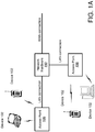
- the network environment includes a wireless communication system that includes one or more access points (APs) 106, one or more wireless communication devices 102 and a network hardware component 192.
- the wireless communication devices 102 can for example include laptop computers 102, tablets 102, personal computers 102, and/or cellular telephone devices 102.
- the details of an embodiment of each wireless communication device 102 and/or AP 106 are described in greater detail with reference to FIGs. 1B and 1C .
- the network environment can be an ad hoc network environment, an infrastructure wireless network environment, a subnet environment, etc., in one embodiment.
- the APs 106 can be operably coupled to the network hardware 192 via local area network connections.
- the network hardware 192 which can include a router, gateway, switch, bridge, modem, system controller, appliance, etc., can provide a local area network connection for the communication system.
- Each of the APs 106 can have an associated antenna or an antenna array to communicate with the wireless communication devices in its area.
- the wireless communication devices 102 can register with a particular AP 106 to receive services from the communication system (e.g., via a SU-MIMO or MU-MIMO configuration). For direct connections (e.g., point-to-point communications), some wireless communication devices can communicate directly via an allocated channel and communications protocol. Some of the wireless communication devices 102 can be mobile or relatively static with respect to AP 106.
- an AP 106 includes a device or module (including a combination of hardware and software) that allows wireless communication devices 102 to connect to a wired network using wireless-fidelity (WiFi), or other standards.
- An AP 106 can sometimes be referred to as a wireless access point (WAP).
- An AP 106 can be implemented (e.g., configured, designed and/or built) for operating in a wireless local area network (WLAN).
- An AP 106 can connect to a router (e.g., via a wired network) as a standalone device in some embodiments. In other embodiments, an AP 106 can be a component of a router.
- An AP 106 can provide multiple devices access to a network.
- An AP 106 can, for example, connect to a wired Ethernet connection and provide wireless connections using radio frequency links for other devices 102 to utilize that wired connection.
- An AP 106 can be implemented to support a standard for sending and receiving data using one or more radio frequencies. Those standards, and the frequencies they use can be defined by the IEEE (e.g., IEEE 802.11 standards).
- An AP 106 can be configured and/or used to support public Internet hotspots, and/or on a network to extend the network's Wi-Fi signal range.
- the access points 106 can be used for (e.g., in-home or in-building) wireless networks (e.g., IEEE 802.11, Bluetooth, ZigBee, any other type of radio frequency based network protocol and/or variations thereof).
- Each of the wireless communication devices 102 can include a built-in radio and/or is coupled to a radio.
- Such wireless communication devices 102 and/or access points 106 can operate in accordance with the various aspects of the disclosure as presented herein to enhance performance, reduce costs and/or size, and/or enhance broadband applications.
- Each wireless communication device 102 can have the capacity to function as a client node seeking access to resources (e.g., data, and connection to networked nodes such as servers) via one or more access points 106.
- the network connections can include any type and/or form of network and can include any of the following: a point-to-point network, a broadcast network, a telecommunications network, a data communication network, and a computer network.
- the topology of the network can be a bus, star, or ring network topology.
- the network can be of any such network topology as known to those ordinarily skilled in the art capable of supporting the operations described herein.
- different types of data can be transmitted via different protocols.
- the same types of data can be transmitted via different protocols.
- the communications device(s) 102 and access point(s) 106 can be deployed as and/or executed on any type and form of computing device, such as a computer, network device or appliance capable of communicating on any type and form of network and performing the operations described herein.
- FIGs. 1B and 1C depict block diagrams of a computing device 100 useful for practicing an embodiment of the wireless communication devices 102 or AP 106. As shown in FIGs. 1B and 1C , each computing device 100 includes a central processing unit 121, and a main memory unit 122. As shown in FIG.
- a computing device 100 can include a storage device 128, an installation device 116, a network interface 118, an I/O controller 123, display devices 124a-124n, a keyboard 126, and a pointing device 127 such as a mouse.
- the storage device 128 can include an operating system and/or software.
- each computing device 100 can also include additional optional elements, such as a memory port 103, a bridge 170, one or more input/output devices 130a-130n, and a cache memory 140 in communication with the central processing unit 121.
- the central processing unit 121 is any logic circuitry that responds to and processes instructions fetched from the main memory unit 122.
- the central processing unit 121 is provided by a microprocessor unit, such as: those manufactured by Intel Corporation of Santa Clara, California; those manufactured by International Business Machines of White Plains, New York ; or those manufactured by Advanced Micro Devices of Sunnyvale, California.
- the computing device 100 can be based on any of these processors, or any other processor capable of operating as described herein.
- Main memory unit 122 can be one or more memory chips capable of storing data and allowing any storage location to be directly accessed by the microprocessor 121, such as any type or variant of Static random access memory (SRAM), Dynamic random access memory (DRAM), Ferroelectric RAM (FRAM), NAND Flash, NOR Flash and Solid State Drives (SSD).
- the main memory 122 can be based on any of the above described memory chips, or any other available memory chips capable of operating as described herein.
- the processor 121 communicates with main memory 122 via a system bus 150 (described in more detail below).
- FIG. 1C depicts an embodiment of a computing device 100 in which the processor communicates directly with main memory 122 via a memory port 103.
- the main memory 122 can be DRDRAM.
- FIG. 1C depicts an embodiment in which the main processor 121 communicates directly with cache memory 140 via a secondary bus, sometimes referred to as a backside bus.
- the main processor 121 communicates with cache memory 140 using the system bus 150.
- Cache memory 140 typically has a faster response time than main memory 122 and is provided by, for example, SRAM, BSRAM, or EDRAM.
- the processor 121 communicates with various I/O devices 130 via a local system bus 150.
- FIG. 1C depicts an embodiment of a computer 100 in which the main processor 121 can communicate directly with I/O device 130b, for example via HYPERTRANSPORT, RAPIDIO, or INFINIBAND communications technology.
- FIG. 1C also depicts an embodiment in which local busses and direct communication are mixed: the processor 121 communicates with I/O device 130a using a local interconnect bus while communicating with I/O device 130b directly.
- I/O devices 130a-130n can be present in the computing device 100.
- Input devices include keyboards, mice, trackpads, trackballs, microphones, dials, touch pads, touch screen, and drawing tablets.
- Output devices include video displays, speakers, inkjet printers, laser printers, projectors and dye-sublimation printers.
- the I/O devices can be controlled by an I/O controller 123 as shown in FIG. 1B .
- the I/O controller can control one or more I/O devices such as a keyboard 126 and a pointing device 127, e.g., a mouse or optical pen.
- an I/O device can also provide storage and/or an installation medium 116 for the computing device 100.
- the computing device 100 can provide USB connections (not shown) to receive handheld USB storage devices such as the USB Flash Drive line of devices manufactured by Twintech Industry, Inc. of Los Alamitos, California.
- the computing device 100 can support any suitable installation device 116, such as a disk drive, a CD-ROM drive, a CD-R/RW drive, a DVD-ROM drive, a flash memory drive, tape drives of various formats, USB device, hard-drive, a network interface, or any other device suitable for installing software and programs.
- the computing device 100 can further include a storage device, such as one or more hard disk drives or redundant arrays of independent disks, for storing an operating system and other related software, and for storing application software programs such as any program or software 120 for implementing (e.g., configured and/or designed for) the systems and methods described herein.
- any of the installation devices 116 could also be used as the storage device.
- the operating system and the software can be run from a bootable medium.
- the computing device 100 can include a network interface 118 to interface to the network 104 through a variety of connections including, but not limited to, standard telephone lines, LAN or WAN links (e.g., 802.11, T1, T3, 56kb, X.25, SNA, DECNET), broadband connections (e.g., ISDN, Frame Relay, ATM, Gigabit Ethernet, Ethernet-over-SONET), wireless connections, or some combination of any or all of the above.
- standard telephone lines LAN or WAN links (e.g., 802.11, T1, T3, 56kb, X.25, SNA, DECNET), broadband connections (e.g., ISDN, Frame Relay, ATM, Gigabit Ethernet, Ethernet-over-SONET), wireless connections, or some combination of any or all of the above.
- LAN or WAN links e.g., 802.11, T1, T3, 56kb, X.25, SNA, DECNET
- broadband connections e.g., ISDN, Frame Relay, ATM,
- Connections can be established using a variety of communication protocols (e.g., TCP/IP, IPX, SPX, NetBIOS, Ethernet, ARCNET, SONET, SDH, Fiber Distributed Data Interface (FDDI), RS232, IEEE 802.11, IEEE 802.11a, IEEE 802.11b, IEEE 802.11g, IEEE 802.11n, IEEE 802.11ac, IEEE 802.11ad, CDMA, GSM, WiMax and direct asynchronous connections).
- the computing device 100 communicates with other computing devices 100' via any type and/or form of gateway or tunneling protocol such as Secure Socket Layer (SSL) or Transport Layer Security (TLS).
- SSL Secure Socket Layer
- TLS Transport Layer Security
- the network interface 118 can include a built-in network adapter, network interface card, PCMCIA network card, card bus network adapter, wireless network adapter, USB network adapter, modem or any other device suitable for interfacing the computing device 100 to any type of network capable of communication and performing the operations described herein.
- the computing device 100 can include or be connected to one or more display devices 124a-124n.
- any of the I/O devices 130a-130n and/or the I/O controller 123 can include any type and/or form of suitable hardware, software, or combination of hardware and software to support, enable or provide for the connection and use of the display device(s) 124a-124n by the computing device 100.
- the computing device 100 can include any type and/or form of video adapter, video card, driver, and/or library to interface, communicate, connect or otherwise use the display device(s) 124a-124n.
- a video adapter can include multiple connectors to interface to the display device(s) 124a-124n.
- the computing device 100 can include multiple video adapters, with each video adapter connected to the display device(s) 124a-124n. In some embodiments, any portion of the operating system of the computing device 100 can be configured for using multiple displays 124a-124n.
- an I/O device 130 can be a bridge between the system bus 150 and an external communication bus, such as a USB bus, an Apple Desktop Bus, an RS-232 serial connection, a SCSI bus, a FireWire bus, a FireWire 800 bus, an Ethernet bus, an AppleTalk bus, a Gigabit Ethernet bus, an Asynchronous Transfer Mode bus, a FibreChannel bus, a Serial Attached small computer system interface bus, a USB connection, or a HDMI bus.
- an external communication bus such as a USB bus, an Apple Desktop Bus, an RS-232 serial connection, a SCSI bus, a FireWire bus, a FireWire 800 bus, an Ethernet bus, an AppleTalk bus, a Gigabit Ethernet bus, an Asynchronous Transfer Mode bus
- a computing device 100 of the sort depicted in FIGs. 1B and 1C can operate under the control of an operating system, which control scheduling of tasks and access to system resources.
- the computing device 100 can be running any operating system such as any of the versions of the MICROSOFT WINDOWS operating systems, the different releases of the Unix and Linux operating systems, any version of the MAC OS for Macintosh computers, any embedded operating system, any real-time operating system, any open source operating system, any proprietary operating system, any operating systems for mobile computing devices, or any other operating system capable of running on the computing device and performing the operations described herein.
- Typical operating systems include, but are not limited to: Android, produced by Google Inc.; WINDOWS 7 and 8, produced by Microsoft Corporation of Redmond, Washington; MAC OS, produced by Apple Computer of Cupertino, California; WebOS, produced by Research In Motion (RIM); OS/2, produced by International Business Machines of Armonk, New York ; and Linux, a freely-available operating system distributed by Caldera Corp. of Salt Lake City, Utah , or any type and/or form of a Unix operating system, among others.
- Android produced by Google Inc.
- WINDOWS 7 and 8 produced by Microsoft Corporation of Redmond, Washington
- MAC OS produced by Apple Computer of Cupertino, California
- WebOS produced by Research In Motion (RIM)
- OS/2 produced by International Business Machines of Armonk, New York
- Linux a freely-available operating system distributed by Caldera Corp. of Salt Lake City, Utah , or any type and/or form of a Unix operating system, among others.
- the computer system 100 can be any workstation, telephone, desktop computer, laptop or notebook computer, server, handheld computer, mobile telephone or other portable telecommunications device, media playing device, a gaming system, mobile computing device, or any other type and/or form of computing, telecommunications or media device that is capable of communication.
- the computing device 100 can have different processors, operating systems, and input devices consistent with the device.
- the computing device 100 is a smart phone, mobile device, tablet or personal digital assistant.
- the computing device 100 can be any workstation, desktop computer, laptop or notebook computer, server, handheld computer, mobile telephone, any other computer, or other form of computing or telecommunications device that is capable of communication and that has sufficient processor power and memory capacity to perform the operations described herein.
- Disclosed herein are related to a system and a method for providing a joint transmission by a group (or plurality) of distributed access points.
- disclosed herein are related to frame formats for sounding and steering of the joint transmission.
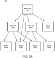
- the access points include a master access point and two or more slave access points capable of transmitting data through a wireless medium.
- the master access point configures or coordinates with different slave access points for a joint transmission.
- a station device may not be able to successfully receive and decode transmission by a single master access point or a single slave access point. However, the station device may successfully receive and decode a joint transmission by two or more access points.
- the master access point configures different station devices for a joint transmission in two phases: a sounding and a steering.
- channel estimation is performed to determine signal strengths, relative signal phases, and/or qualities of transmissions from different access points received by station devices, and/or to determine a configuration of a joint transmission according to the determined signal strengths, relative signal phases, or qualities of transmissions from different access points.
- Examples of the configuration of the joint transmission can include timing, power, gain, channel bandwidth, frequency for transmission through one or more antennas, steering vector, or any information indicating how to radiate energy in a particular direction, frequency-dependency within a channel, signal-to-noise ratio (SNR), and/or appropriate data rate adjustments.
- SNR signal-to-noise ratio
- the access points and the station devices can communicate through a beamforming according to the configuration determined during the sounding, such that the station devices can receive and decode joint transmissions from the access points.
- the frame formats disclosed herein can enable slave access points to estimate or determine synchronization information for joint transmission with a master access point.
- the synchronization information can include a carrier frequency offset, a sampling frequency offset, a first reference value for a common phase offset, and/or a second reference value for a timing offset with respect to the master access point.
- the master access point transmits a slave trigger frame or a preamble of a null data packet that enables slave access points to estimate or determine synchronization information.
- the master access point and the slave access points may transmit together simultaneously for sounding, steering or both.
- the AP 106 (hereinafter sometimes generally referred to as an "access point" or "AP"), for example in a MU-MIMO configuration, can include an AP 106 that can communicate with each of a plurality of devices 102 (e.g., beamformees).
- the AP 106 can include a number of antennas and can support a number of spatial streams for transmission to a device (sometimes referred to as a station (STA) or user) 102.
- STA station
- An AP 106 can leverage and use one or more sounding frames, such as null data packet (NDP) or NDP announcement (NDPA) frames or other control frames, to request the device 102 for channel estimation feedback.
- NDP null data packet
- NDPA NDP announcement
- the dimension of the AP 106 sometimes refers to the number of spatial streams or the number of available transmit antennas the AP 106 supports.
- the dimension of the wireless communication device 102 sometimes refers to the number of spatial streams the device 102 can support, e.g., for channel estimation.
- the present methods and systems can allow a higher dimension AP 106 or a coordinated set of APs 106 (both hereafter sometimes generally referred to as a single "beamformer", wherein the coordinated set of APs 106 can be configured to operate in some ways like a single beamformer), to use the beamformer's transmission antennas to steer and achieve full array gain even if paired against a device 102 of lower dimension.
- the device 102 can be capable of supporting less than the number of spatial streams that the AP 106 can include in a sounding, for performing multi-input multi-output (MIMO) channel estimation.
- MIMO multi-input multi-output
- the present solution can provide for multiple soundings using subsets of the beamformer's antennas, in place of a single sounding using all of the beamformer's antennas (which the beamformee does not support).
- a coordinated sequence of soundings from subsets of antennas can elicit different sets of MIMO channel estimation results from a low dimensional beamformee, which can be combined to produce full channel estimation information.
- the channel estimation feedback matrices for the different subsets/soundings can be merged or combined to yield channel estimation for the full channel of the AP 106.
- multiple beamformers can operate in a coordinated fashion as if a higher dimensional beamformer is communicating with one or more beamformee(s). Multiple sounding reports from the same device 102 to the different APs 106 can be combined and/or shared between the coordinated APs 106, to understand the MU-MIMO channels between each beamformer-beamformee pair.
- the coordinated APs 106 can be time and/or frequency synchronized (e.g., using frequency diversity or offset) to provide a sounding sequence that can appear like a single sounding sequence from a higher dimension beamformer.
- the AP 106 can receive responses from the device 102, e.g., embodied as a beamformee, to the plurality of sounding frames.
- the responses can include channel estimation for the plurality of subsets of transmit spatial streams.
- the AP 106 can generate full channel estimation information based on the received responses.
- the full channel estimation information can include channel estimation information corresponding to all the transmit spatial streams that the AP 106 can provide.
- the AP 106 can steer the plurality of transmit antennas of the AP 106 based on the full channel estimation information.
- this disclosure is directed to a method for performing channel estimation between a plurality of APs 106 embodied as beamformers and at least one device 102 embodied as a beamformee.
- the method can include configuring a first AP 106 and a second AP 106 to communicate with a first device 102.
- the first AP 106 can support a first plurality of transmit spatial streams.
- the second AP 106 can support a second plurality of transmit spatial streams.
- the first AP 106 and the second AP 106 can determine, between the first AP 106 and the second AP 106, a plurality of subsets of transmit spatial streams from the first plurality of transmit spatial streams and the second plurality of transmit spatial streams.
- the first AP 106 and the second AP 106 can coordinate, between the first and the second beamformers 106, transmission of a plurality of sounding frames to the first device 102 for channel estimation based at least on the determined plurality of subsets of transmit spatial streams.
- the first AP 106 and the second AP 106 are configured to communicate with the first device 102.
- the first AP 106 and the second AP 106 can be operably coupled via a backbone connection.
- the first AP 106 and/or the second AP 106 can combine at least some responses from the first device 102 to the plurality of sounding frames, the responses including channel estimation for the plurality of subsets of transmit spatial streams.
- the first AP 106 and/or the second AP 106 can generate full channel estimation information between the first AP 106 and the second AP 106, based on the combination of the at least some responses.
- the first AP 106 and the second AP 106 can be configured to communicate with a plurality of beamformees 102.
- the first AP 106 and the second AP 106 can coordinate, between the first AP 106 and the second AP 106, transmission of a plurality of sounding frames to a plurality of the devices 102.
- the first AP 106 and/or a second AP 106 can use frequency diversity to simultaneously send a sounding frame from the first AP 106 and a sounding frame from the second AP 106.
- the AP 106 can include a wireless transceiver 228, a soundings controller module (SCM) 222 (also referred to as “a soundings controller 222"), a steering controller module 225 (also referred to as "a steering controller 225"), an integration module 221 (also referred to as "an integration controller 221”), a storage module 223 and/or a configuration 224.
- SCM soundings controller module
- a steering controller module 225 also referred to as "a steering controller 225”
- an integration module 221 also referred to as "an integration controller 221”
- storage module 223 and/or a configuration 224.
- the device 102 can include a wireless transceiver and a channel estimation module (CEM) 212 (also referred to as "a channel estimation controller 212").
- CEM channel estimation module
- the AP 106 can include a plurality of antennas (e.g., phase array antennas).
- the system can support at least some aspects of a MU-MIMO transmission configuration 224 between the AP 106 embodied as a beamformer and the device 102 embodied as a beamformee.
- the AP 106 can be of higher dimensionality relative to the device 102.
- the device 102 can perform channel estimation for a number of spatial communication streams up to the dimensionality of the device 102.
- Device 102 can provide channel estimation for more dimensions than it has antennas in one embodiment. For example, device 102 can have only one antenna but can have the capability to estimate a three antenna channel.
- the AP 106 can be of higher dimensionality and/or capability than some of the devices 102 (e.g., older generation beamformees) in deployment.
- the device 102 can for example be capable of performing channel estimation for up to a pre-configured number of transmit spatial streams from the AP 106, the pre-configured number of transmit spatial streams being less than a number of transmit spatial streams that the AP 106 can provide.
- the AP 106 can be implemented (e.g., configured and/or built) to support, simultaneously or otherwise, a first number of transmit streams, channels or connections, for instance within a transmission or sounding frame.
- the AP 106 can include a coordinated set of APs 106.
- the sounding frame can include an MU-MIMO frame, SU-MIMO frame and/or an NDP frame.
- the AP 106 can be implemented to include a first number of transmit chains and/or transmit antennas.
- the device 102 can be implemented to support (simultaneously or otherwise) a second number of spatial streams, channels or connections (hereafter sometimes generally referred to as "spatial streams" or "Nss").
- the second number of spatial streams can be lower than the first number of streams.
- a total or predetermined number of spatial streams that a device 102 can support can be stored or indicated in the beamformee's capability field - "Compressed Steering Number of Beamformer Antennas Supported.”
- This field can be defined or included in a management frame.
- This field can include or indicate a Nss that the AP 106 can handle or support in an NDP frame, for example.
- This field can set the range of transmit spatial dimensions for which the device 102 can perform channel estimation, generate a proper beamforming report, and/or create a sounding feedback frame (sometimes generally referred to as a "response") to the AP 106.
- this capability is fixed once the device 102 or AP 106 is implemented and/or deployed in the field, and in some embodiments not upgradable (e.g., through a software patch).
- the pre-configured or ceiling Nss of the device 102 can limit transmit beamforming performance, e.g., of the AP 106 and/or the device 102.
- transmit beamforming performance e.g., of the AP 106 and/or the device 102.
- the AP 106 might not be able to use all of its transmit antennas for steering, and might not be able to achieve full array gain.
- the AP 106 might have to use the minimal sounding capability among the devices 102 with different sounding capabilities.
- the AP 106 might have to turn on fewer than the full set of antennas, corresponding to the minimal sounding capability.
- TXBF transmit-beamforming
- the AP 106 includes a transceiver 228 allowing the beamformer 106 to communicate with other devices (e.g., beamformee 102 or another beamformer 106) through one or more antennas.
- the transceiver 228 includes a transmitter that encodes data (e.g., content data, control data, response data, announcement, etc.) at a baseband frequency, upconverts the encoded data to a radio frequency, and transmits the upconverted signal through one or more antennas.
- data e.g., content data, control data, response data, announcement, etc.
- the transceiver 228 includes a receiver that downconverts a wireless signal at a radio frequency received through one or more antennas to a baseband frequency, and decodes the converted signal to obtain data (e.g., content data, control data, response data, announcement, etc.).
- data e.g., content data, control data, response data, announcement, etc.
- the AP 106 transmits and receives data at the same frequency, separate frequencies, or at overlapping frequencies.
- the AP 106 includes a SCM 222.
- the SCM 222 can manage and/or control transmission of a plurality of sounding frames (e.g., NDP sounding frames) to a low-capability device 102.
- the SCM 222 can include hardware, or a combination of hardware and software.
- the SCM 222 can include any application, program, library, script, task, service, process or any type and form of executable instructions executing on hardware of the AP 106.
- the SCM 222 includes a set of executable instructions executing on a core or processor of the AP 106.
- the SCM 222 can include circuitry designed and/or constructed to perform any of the operations and functions described herein.
- the SCM 222 is configured to control transmission of sounding frames to the device 102 via one or more antennas of the AP 106.
- the SCM 222 can be configured to allocate, select or assign certain antennas to participate in one or more soundings within a set of soundings.
- the SCM 222 can for example tune a subset of the beamformer's antennas (e.g., phase array antennas) to participate in a particular sounding.
- the SCM 222 of a master AP determines, instructs, or schedules, a sounding sequence, as disclosed herein.
- the SCMs 222 of different APs coordinate with each other to determine or schedule the sounding sequence disclosed herein.
- the SCM 222 includes firmware executing on the AP 106 hardware.
- the firmware can operate in a layer of a protocol stack of the AP 106 (e.g., in an upper layer).
- the SCM 222 operates in the MAC layer, e.g., residing between a lower layer of MAC and a higher layer of MAC.
- the AP 106 or SCM 222 can partition, allocate or otherwise assign the plurality of antennas into a plurality of subsets of antennas, e.g., based on a configuration 224. In some embodiments, an antenna can be assigned to more than one of the subsets.
- Each subset of antennas can be selected according to a configuration 224, which can be consistent with one or more predefined rules, policies, requirements and/or guidelines.
- each subset of antennas can include antennas physically adjacent to each other on the AP 106, and/or selected according to a certain order or sequence.
- each subset of antennas can include antennas that are separated from each other by at least another antenna not in the subset, e.g., to include some spatial degree of freedom or separation.
- the SCM 222 configures each subset to include at least one antenna common to at least one other subset.
- the SCM 222 can manage or control the transmission of a plurality of sounding frames corresponding to the subsets of antennas. Each sounding can cover a subset of the AP's antennas.
- the SCM 222 or AP 106 can instruct, cause, or allow the coordinated transmission in sounding frames through different antennas in a particular order.
- the SCM 222 or AP 106 can cause the transceiver 228 to transmit the soundings frames distributed or staggered over a period of time, e.g., at predefined intervals.
- the SCM 222 or AP 106 can provide sufficient time for the AP 106 to process each sounding frame and/or provide a response to each sounding frame, before sending a next sounding frame.
- the SCM 222 can store information about the configured subsets, and/or information about a sequence of corresponding soundings, to the configuration 224 and/or storage module 223.
- the configuration 224 can include, maintain or store information about assignment or allocation of antennas to subsets for sounding purposes, and/or information about a sequence of soundings corresponding to the configured subsets.
- the configuration 224 can include information about connecting or coupling a specific antenna to a particular transmit chain.
- the configuration 224 can include a schedule or timing information for performing soundings.
- the configuration 224 can be stored in a storage module 223.
- the storage module 223 can include one or more interconnected storage devices, such as any embodiment of storage devices 128, 140, 122, described above in connection with FIGs. 1B and 1C .
- the SCM 222 and/or the integration module can generate, access and/or update the configuration.
- the configuration 224 can include a list, table or other database structure, and can include at least one entry, record or specification corresponding to each device 102 for example.
- the configuration 224 can be specified and/or defined in a file or a collection of records, stored or maintained in the storage module 223.
- a SCM 222 and/or integration module 221 can access a portion of the configuration, to implement partial channel estimation through multiple soundings.
- an integration module can use a hash to perform lookup in the configuration 224 for an antenna or device, to process channel estimation feedback.
- the device 102 includes a CEM 212.
- the CEM 212 can process a sounding frame received by the device 102.
- the CEM 212 can perform channel estimation and/or provide channel estimation feedback.
- Channel estimation can include any form of channel measurement and/or calibration, or channel response determination.
- Channel estimation results can be used to provide feedback to the AP 106 on how to radiate energy in a particular direction, frequency-dependency within a channel, signal-to-noise ratio (SNR), and/or appropriate data rate adjustments, for example.
- the CEM 212 can include hardware, or a combination of hardware and software.
- the CEM 212 can include any application, program, library, script, task, service, process or any type and form of executable instructions executing on hardware of the CEM 212.
- the CEM 212 includes a set of executable instructions executing on a core or processor of the CEM 212.
- the CEM 212 can include circuitry designed and/or constructed to perform any of the operations and functions described herein.
- the CEM 212 is pre-configured to perform channel estimation in a particular environment, e.g., a SU-MIMO or MU-MIMO environment.
- the CEM 212 includes firmware executing on the hardware of the device 102.
- the firmware can operate in a layer of a protocol stack of the device 102 (e.g., in an upper layer).
- the CEM 212 can operate in the MAC layer, e.g., residing between a lower layer of MAC and a higher layer of MAC.
- the CEM 212 can provide the channel estimation feedback for inclusion in a response to a sounding frame from the AP 106.
- the CEM 212 can manage or direct the transmission of one or more responses to the AP 106.
- the AP 106 can include an integration module 221.
- the integration module 221 can manage, track and/or process the responses received from the device 102.
- the integration module 221 can store information (e.g., channel estimation information) from one or more responses in a storage module 223.
- the integration module 221 can order and/or combine channel estimation information from the response, for example, based at least in part on information stored in the configuration 224 (e.g., information about the configured subsets, and/or the sequence of soundings corresponding to the configured subsets).
- the integration module 221 may determine steering information.
- the steering information indicates configuration of the transceiver 228 of the AP 106 and/or other APs 106 for steering.
- the steering information indicates timing, power, gain, channel bandwidth, frequency for transmission through one or more antennas, steering vector, or indicates how to radiate energy in a particular direction, frequency-dependency within a channel, signal-to-noise ratio (SNR), and/or appropriate data rate adjustments for joint transmission with other access points.
- SNR signal-to-noise ratio
- the integration module 221 can include hardware, or a combination of hardware and software.
- the integration module 221 can include any application, program, library, script, task, service, process or any type and form of executable instructions executing on hardware of the AP 106.
- the integration module 221 includes a set of executable instructions executing on a core or processor of the AP 106.
- the integration module 221 can include circuitry designed and/or constructed to perform any of the operations and functions described herein.
- the integration module 221 includes firmware executing on the hardware of the AP 106.
- the firmware can operate in a layer of a protocol stack of the AP 106 (e.g., in an upper layer).
- the integration module 221 operates in the MAC layer, e.g., residing between a lower layer of MAC and a higher layer of MAC. In some embodiments, the integration module 221 is configured to combine, integrate, merge, normalize, adjust and/or aggregate information from the responses to obtain full channel information. In some embodiments, the integration module 221 is integrated with the soundings controller 222 or is implemented as part of the soundings controller 222.
- the AP 106 includes a steering module 225.
- the steering module 225 can manage and/or control transmission of steered frames to a low-capability device 102.
- the steering module 225 can include hardware, or a combination of hardware and software.
- the steering module 225 can include any application, program, library, script, task, service, process or any type and form of executable instructions executing on hardware of the AP 106.
- the steering module 225 includes a set of executable instructions executing on a core or processor of the AP 106.
- the steering module 225 can include circuitry designed and/or constructed to perform any of the operations and functions described herein.
- the steering module 225 is configured to control transmission of steered frames to the device 102 via one or more antennas of the AP 106.
- the steering module 225 can be configured to allocate, select or assign certain antennas to participate in one or more steerings.
- the steering module 225 can for example tune a subset of the beamformer's antennas (e.g., phase array antennas) to participate in a particular steering.
- the steering module 225 includes firmware executing on the AP 106 hardware.
- the firmware can operate in a layer of a protocol stack of the AP 106 (e.g., in an upper layer).
- the steering module 225 operates in the MAC layer, e.g., residing between a lower layer of MAC and a higher layer of MAC.
- the AP 106 or steering module 225 can partition, allocate or otherwise assign the plurality of antennas into a plurality of subsets of antennas, e.g., based on a configuration 224 or the integration module 221. In some embodiments, an antenna can be assigned to more than one of the subsets.
- Each subset of antennas can be selected according to a configuration 224 and/or by the integration module 221, which can be consistent with one or more predefined rules, policies, requirements and/or guidelines.
- each subset of antennas can include antennas physically adjacent to each other on the AP 106, and/or selected according to a certain order or sequence.
- each subset of antennas can include antennas that are separated from each other by at least another antenna not in the subset, e.g., to include some spatial degree of freedom or separation.
- the steering module 225 configures each subset to include at least one antenna common to at least one other subset.
- the steering module 225 can manage or control transmission of data (e.g., content data) corresponding to the subsets of antennas.
- the steering module 225 can cause the coordinated transmission or joint transmission of content data in steered frames through different antennas or with another AP 106 in a particular order.
- the steering module 225 may transmit according to the steering information (e.g., steering vector).
- the steering module 225 can cause the transceiver 228 to transmit the steered frames distributed or staggered over a period of time, e.g., at predefined intervals.
- the steering module 225 can provide sufficient time for another AP 106 or a device 102 to process each steering and/or provide a response to each steering, before sending a next steered frame.
- the present methods can be implemented or applied transparent to a low capability device 102.
- the device 102 might not even realize or be aware that the multiple access points 106 are coordinated and transmit sounding frames or steered frames simultaneously.
- a high dimensional transmit structure (e.g., a single AP 106) can be formed by combining and/or coordinating two or more lower dimensionality beamformers 106.
- FIG. 2B an embodiment of a system for performing sounding and steering between at least one AP 106 and at least one device 102 is depicted.
- the system can include at least two APs operably coupled together to effectively operate as a single AP 106 (hereafter sometimes referred to as "coordinated beamformers" or as a single “beamformer”).
- the coordinated beamformers can be in communication with one or more devices 102 embodied as beamformees.
- the coordinated beamformers can include a transceiver 228, a SCM 222, an integration module 221, a steering module 225, a storage module 223 and/or a configuration 224, each of which can include one or more features described above in connection with FIG. 2A .
- Each of these modules can reside on at least one of the coordinated beamformers (APs 106), distributed among different APs 106, or can reside at one or more networked locations.
- an array gain can be represented by 10*log10(NTX/Nss) dB, and a corresponding diversity order can be represented as NTX*NRX, where NTX can represent the number of transmit antennas, and NRX can represent the number of receive antennas.
- NTX can represent the number of transmit antennas
- NRX can represent the number of receive antennas.
- a large number of transmit antennas at the beamformer side can provide more spatial degrees of freedom, e.g., allowing for improved link quality.
- total capacity of the system can increase linearly with respect to the number of beamformer antennas (e.g., in an asymptotic sense).
- a larger number of transmit antennas can support or host more beamformees (e.g., multi-user STAs), for instance using a multi-user steered frame to achieve better spectrum efficiency.
- a larger number of transmit antennas can allow for better multi-user precoding matrices for a given set of beamformees (e.g., multi-user STAs).
- a significant portion of existing access points 106 can be implemented with a limited number of transmit antennas, e.g., up to three antennas.
- transmit antennas from a few low dimensional beamformers 106 can be combined or aggregated to achieve better performance.
- multiple lower dimensional APs 106 are connected to each other, for example through an Ethernet backbone or other connection (e.g., a wireless connection such as Wi-Fi, cellular, Bluetooth, etc.). These APs 106 can be coordinated to generate multiple sounding sequences between the APs 106 and the devices 102, to determine the channels (e.g., MU-MIMO channels) between each beamformer-beamformee pair. Sounding feedback reports from different devices 102 can be shared and/or processed between the coordinated beamformers (e.g., APs 106), for example, using the techniques described in connection with at least FIGs. 2A and 2B .
- an Ethernet backbone or other connection e.g., a wireless connection such as Wi-Fi, cellular, Bluetooth, etc.
- These APs 106 can be coordinated to generate multiple sounding sequences between the APs 106 and the devices 102, to determine the channels (e.g., MU-MIMO channels) between each beamformer-beamforme
- multiple sounding feedback reports from the same device 102 to multiple APs 106 can be combined in such a way as if the APs 106 include a single higher dimensional AP 106 communicating to the device 102.
- Multi-user precoding can be performed, for example, using post-combined MU-MIMO channels.
- the coordinated beamformers 106 might have to coordinate the steered frame transmission so that the steered frame as formed appears to come from a larger dimensional AP 106 rather than several different lower dimensional APs 106.
- the coordinated APs 106 can be time synchronized.
- the APs 106 can coordinate steered frame transmission through a backbone Ethernet or other connection (e.g., a wireless connection such as Wi-Fi, cellular, Bluetooth, etc.).
- the system can time and/or frequency synchronize the coordinated APs 106, for example by adjusting frame timing and/or carrier frequency offset (CFO).
- the coordinated APs 106 can transmit sounding frames, steered frames, or a combination of them in a coordinated manner as if the frames are sent from a single larger dimensional AP 106.
- the precoding matrix and/or steered frame can be formed in a coordinated manner.
- the coordinated APs 106 might have to coordinate the steered frame transmission so that the steered frame as formed appears to come from a larger dimensional AP 106 rather than several different lower dimensional APs 106.
- the coordinated APs 106 can synchronize their carrier frequency offset or CFO. This can be performed by observing uplink transmission from different devices 102, sharing the CFO among the APs 106.
- the coordinated APs 106 can be time synchronized. For example, one of the APs 106 can begin frame transmission first (e.g., L-STF and L-LTF signals transmitted first). The rest of the coordinated APs 106 can join in the transmission starting from the VHT-STF signal, for example by monitoring for presence and/or timing of the L-STF and L-LTF signal on the air.
- FIG. 3A is a block diagram illustrating an example network environment 300 including a master AP 310 and multiple slave APs 320A, 320B for a joint transmission to stations devices 330A-330E, according to some embodiments.
- each of the master AP 310 and the slave APs 320A, 320B, or the combination of the master AP 310 and the slave APs 320A, 320B is implemented or operate as the beamformer 106 of FIG. 2A and 2B .
- the network environment 300 includes more, fewer or different components than shown in FIG. 3A .
- the master AP 310 is capable of directly communicating with the slave APs 320A, 320B, and the station devices 330A, 330C through a wireless medium, but may be incapable of directly communicating with the station devices 330B, 330D, 330E alone.
- the station devices 330A, 330C can successfully receive and decode a wireless transmission by the master AP 310 alone, but the station devices 330B, 330D, 330E may not successfully receive and decode the wireless transmission by the master AP 310 alone.
- the slave AP 320A is capable of directly communicating with the master AP 310 and the station devices 330B, 330C, 330D.
- the slave AP 320B is capable of directly communicating with the master AP 310 and the station devices 330C, 330D, 330E.
- the master AP 310 configures, causes, or instructs the slave APs 320A, 320B for a joint transmission.
- the station devices 330A-330E can successfully receive and decode the joint transmission by the master AP 310 and the slave APs 320A, 320B.
- the master AP 310 and the slave APs 320A, 320B communicate with each other through a wireless medium in a particular frame format to enable a joint transmission.
- a frame format disclosed herein enables the slave APs 320A, 320B to estimate or determine synchronization information for a joint transmission with the master AP 310.
- the synchronization information examples include a carrier frequency offset (CFO), a sampling frequency offset (SFO), a phase offset (PO), a timing offset (TO), a first reference value for a common phase offset, and/or a second reference value for a timing offset with respect to the master AP 310.
- the master AP 310 transmits, to the slave APs 320A, 320B, a slave trigger frame or a preamble of a null data packet including information that enables the slave APs 320A, 320B to estimate or determine synchronization information.
- the synchronization information is determined according to a difference of measurements obtained in the sounding sequence and the steering sequence.
- the slave AP uses the channel estimations, denoted here by the vectors h_ndp (for the channel before the NDP) and h_data (for the channel before the joint data transmission) to calculate two parameters related to the phase drift: timing errors (or acquisition error) and a common phase drift.
- the timing errors are manifested as a linear phase drift across frequency, where the common phase drift is due to different RF clocks and phase noise between the maser AP 310 and the slave AP 320.
- h_data i h_ndp i e j ⁇ i + ⁇ + N i
- N i is a noise component for the tone i
- ⁇ corresponds to the timing error
- ⁇ corresponds to the common phase drift
- N i ⁇ is a modified noise component for the tone i.
- this metric is summed up across the receive antennas, in some embodiments.
- synchronization information can be determined.
- the master AP 310 and the slave APs 320A, 320B may perform a joint transmission.
- FIG. 3B is a flow chart illustrating an example process 350 of establishing an example multiple-input multiple-output (MIMO) communication, according to some embodiments.
- the process 350 is performed by the master AP 310, or by the master AP 310 and the slave APs 320A, 320B.
- the process 350 is performed by other entities.
- the process 350 includes more, fewer, or different steps than shown in FIG. 3B .
- the master AP 310 and the slave APs 320A, 320B perform 360 sounding.
- a soundings controller 222 of the master AP 310 may initiate a sounding to obtain or gather channel estimation information.
- the soundings controller 222 of the master AP 310 may cause the transceiver 228 of the master AP 310 to transmit through a wireless medium, to the slave APs 320A, 320B, a frame or a portion of the frame that allows the slave APs 320A, 320B to obtain synchronization information for a joint transmission to perform sounding.
- the soundings controller 222 of the master AP 310 causes the transceiver 228 of the master AP 310 to transmit a slave trigger frame or a preamble of a null data packet frame that allows soundings controllers 222 of the slave APs 320A, 320B to determine or estimate a carrier frequency offset, a sampling frequency offset, a phase offset, a timing offset, a first reference value for a common phase offset, and/or a second reference value for a timing offset with respect to the master AP 310.
- the slave APs 320A, 320B can estimate the change in phase/timing offset between sounding and steering (via the preceding trigger frames), according to Eq. (1)-(4) above.
- the soundings controller 222 of the master AP 310 causes the transceiver 228 of the master AP 310 to transmit a portion of a frame (e.g., NDP frame) to the station devices 330A-330E to cause the station devices 330A-330E to perform channel estimations.
- a frame e.g., NDP frame
- the soundings controllers 222 of the slave APs 320A, 320B may cause transceivers 228 of the slave APs 320A, 320B to transmit the portion of the frame to the station devices 330A-330E according to the synchronization information, while the master AP 310 transmits the portion of the frame (e.g., NDP frame).
- the joint transmission by the master AP 310 and the slave APs 320A, 320B allows the station devices 330A-330E to successfully receive and decode the portion of the frame.
- the station devices 330A-330E may measure or determine signal strengths and/or signal qualities of the joint transmission for sounding, and generate channel estimation information indicating the measured signal strengths or signal qualities. Detailed descriptions on example frame formats and operations of sounding are provided below with respect to FIGs. 5-9 .
- the master AP 310 generates 365 steering information in response to the channel estimation information.
- the integration module 221 of the master AP 310 receives and integrates channel estimation information from different station devices 330A-330B, and determines or generates steering information to perform steering according to the integrated channel estimation information.
- the steering information indicates, for each AP, configuration of the transceiver 228 for steering.
- the steering information indicates timing, power, gain, channel bandwidth, frequency for transmission through one or more antennas, steering vector, or indicates how to radiate energy in a particular direction, frequency-dependency within a channel, signal-to-noise ratio (SNR), and/or appropriate data rate adjustments for joint transmission with other access points.
- SNR signal-to-noise ratio
- the integration module 221 of the master AP 310 generates the steering information according to the channel estimation information, that allows joint transmission by the access points 310, 320A, 320B.
- the master AP 310 generates the steering information and shares the steering information with the slave APs 320A, 320B.
- each slave AP 320 generates the steering information for itself, provided that the same channel information is available at all APs.
- the master AP 310 performs 370 steering according to the steering information.
- a steering controller 225 of the master AP 310 may initiate a steering.
- the steering controller 225 of the master AP 310 may cause the transceiver 228 of the master AP 310 to transmit, to the slave APs 320A, 320B, a frame that allows the slave APs 320A, 320B to obtain synchronization information for a joint transmission to perform steering.
- the steering controller 225 of the master AP 310 causes the transceiver 228 of the master AP 310 to transmit a slave trigger frame or a preamble of a steered frame that allows steering controllers 225 of the slave APs 320A, 320B to determine or estimate a carrier frequency offset, a sampling frequency offset, a phase offset, a timing offset, a first reference value for a common phase offset, and/or a second reference value for a timing offset with respect to the master AP 310.
- the slave APs 320A, 320B can estimate the change in phase/timing offset between sounding and steering (via the preceding trigger frames), according to Eq. (1)-(4) above.
- the steering controller 225 of the master AP 310 causes the transceiver 228 of the master AP 310 to transmit a portion of a steered frame to the station devices 330A-330E.
- the portion of the steered frame may include content data (e.g., text, image, video, or any data).
- the steering controller 225 of the slave APs 320A, 320B may cause transceivers 228 of the slave APs 320A, 320B to transmit the portion of the steered frame to the station devices 330A-330E according to the synchronization information, while the master AP 310 transmits the portion of the steered frame.
- the joint transmission by the master AP 310 and the slave APs 320A, 320B allows the station devices 330A-330E to successfully receive and decode the portion of the steered frame and extract content data from the steered frame.
- Detailed descriptions on example frame formats and operations of steering are provided below with respect to FIGs. 10-13 .
- FIG. 4 illustrates an example timing diagram of a joint transmission by a master AP and a slave AP to a station device.
- the soundings controller 222 of the master AP causes or configures its transceiver 228 to communicate with the slave AP and the station device.
- the soundings controller 222 of the slave AP causes or configures its transceiver 228 to communicate with the master AP and the station device.
- a different number of master APs, slave APs, or station devices may be included for the joint transmission.
- the soundings controller 222 of the master AP causes or configures the transceiver 228 of the master AP to transmit 410 a slave trigger frame to the slave AP.
- a slave trigger frame is a frame transmitted by a master AP for triggering some or all slave APs to transmit a subsequent frame jointly.
- the slave trigger frame is similar to a trigger frame for HE TB PPDU in 802.11ax.
- the slave trigger frame may be replaced by a preamble of a subsequent frame.
- the slave trigger frame indicates which slave APs to participate in the subsequent joint transmission, which could change dynamically from one joint TX to the next.
- the slave trigger frame allows slave APs to estimate their CFO/SFO, phase-offset (PO), timing-offset (TO), a reference value for PO, and/or a reference value for TO relative to master AP, by means of long training fields (LTFs) included in the frame.
- LTFs long training fields
- the number of LTFs may be larger than the number sufficient for the channel estimation.
- these LTFs may be located non-contiguously in the frame, e.g., in mid-ambles or in a post-amble.
- the slave trigger frame contains PHY/MAC level information to construct and transmit subsequent frame jointly, e.g., and may contain frame-type/purpose, rate, receiver MAC address(es), payload, etc.
- the slave trigger frame contains data for slave AP to be used in future joint AP transmissions either in a subsequent packet or within the same packet with some delay.
- the soundings controller 222 of the slave AP causes or configures its transceiver 228 to receive the slave trigger frame, and decodes the slave trigger frame to generate 415 synchronization information by estimating CFO, SFO, PO, TO, a reference value for PO, and/or a reference value for TO with respect to the master AP.
- the slave trigger frame may not be successfully heard or decoded 418 by station devices.
- the soundings controller 222 of the master AP causes its transceiver 228 to transmit 420 a joint frame to a station device, for example, after a short inter-frame spacing (SIFS) following the end of the slave trigger frame. During the short inter-frame spacing, the master AP and the slave AP may not transmit. In one aspect, the soundings controller 222 of the slave AP causes its transceiver 228 to transmit 422 the joint frame to the station device, while the master AP transmits 420 the joint frame.
- SIFS short inter-frame spacing
- the soundings controller 222 of the slave AP may correct for their CFO, SFO, PO, TO, a reference value for PO, and/or a reference value for TO with respect to the master AP and jointly transmit with the master AP.
- CSI-dependent steering vectors may not be applied, such that the joint transmission by the master AP and the slave AP may not be beamformed.
- the joint transmission may be broadcast/multicast, or unicast in the absence of CSI.
- some or all APs transmit identical preambles and payloads in the joint frame, encoded at the same PHY rate.
- the soundings controllers 222 of APs modulate signals for transmission with a different set of cyclic delays, to avoid unintentional beamforming, such as in 802.11n/ac/ax single-user transmissions.
- the station device receives the joint transmission by the master AP and the slave AP, and processes or decodes 428 the joint transmission. For example, the station device measures or determines signal strengths or signal qualities of the joint transmission, and generates channel estimation information indicating the measured signal strengths or signal qualities. In some embodiments, the station device transmits or provides the channel estimation information to the master AP, the slave AP, or any AP.
- FIG. 5 illustrates an example timing diagram of a sounding sequence, according to some embodiments.
- the master AP and the slave AP perform a joint transmission for sounding.
- a different number of master APs, slave APs, or station devices may be included for the joint transmission.
- the soundings controller 222 of the master AP configures or causes its transceiver to transmit 510 a slave trigger frame to the slave AP.
- the slave trigger frame alerts the slave AP to commence the sounding sequence.
- the slave trigger frame contains information to be transmitted in subsequent NDP announcement frame jointly with the slave AP jointly.
- the slave trigger frame indicates contents of preamble 2 and/or a number of LTFs in a NDP frame.
- the slave trigger frame may be decoded by some or all slave APs.
- the soundings controller 222 of the slave AP estimates 515 synchronization information for an NDP announcement frame.
- the soundings controller 222 of the slave AP measures or estimates CFO, SFO, PO, TO, a reference value for PO, and/or a reference value for TO relative to master AP, and synchronizes with the master AP for the subsequent NDP announcement frame according to the CFO, SFO, PO, TO, a reference value for PO, and/or a reference value for TO.
- the station device 518 may or may not decode the slave trigger frame.
- the soundings controller 222 of the master AP causes its transceiver 228 to transmit 520 a NDP announcement frame to a station device, for example, after a SIFS following the end of the slave trigger frame. During the short inter-frame spacing, the master AP and the slave AP may not transmit.
- an NDP announcement frame contains information on which station devices are expected to feedback channel information, and a type of channel information.
- the soundings controller 222 of the slave AP causes its transceiver 228 to transmit 522 the NDP announcement frame to the station device, while the master AP transmits 520 the NDP announcement frame.
- the slave AP synchronizes with the master AP, according to the synchronization information for the joint transmission of the NDP announcement frame.
- the station device may receive the joint transmission of the NDP announcement frame by the master AP and the slave AP, and prepare 528 for subsequent NDP frame, similar to HE/VHT sounding sequence.
- the station device checks if the station device is on a list of devices supposed to receive the subsequent NDP frame.
- the soundings controller 222 of the master AP causes its transceiver 228 to transmit a NDP, for example, after a SIFS following the end of the NDP announcement frame.
- the master AP and the slave AP may not transmit.
- the NDP frame includes a preamble 1, preamble 2, and LTFs.
- the preamble 1 is transmitted 530 by the master AP but not by the slave AP.
- the slave AP receives the preamble 1 and estimates 535 or updates synchronization information (e.g., CFO, SFO, PO, TO, a reference value for PO, and/or a reference value for TO with respect to the master AP) according to the preamble 1.
- the preamble 1 allows the slave AP sufficient time to switch from a receive mode to a transmit mode for the joint transmission of the remaining portion of the NDP frame.
- the preamble 1 indicates contents of a portion of a subsequent frame (e.g., preamble 2) and/or the number of LTFs.
- the station device may not hear/decode 538 the preamble 1, or may choose to ignore the preamble 1.
- the soundings controller 222 of the master AP causes its transceiver 228 to transmit 540 the preamble 2 subsequent to the end of the preamble 1.
- the soundings controller 222 of the slave AP causes its transceiver 228 to transmit 542 the preamble 2 to the station device according to the synchronization information, while the master AP transmits the preamble 2.
- the joint transmission of the preamble 2 by the master AP and the slave AP causes or allows the station device to receive, decode, and/or process LTFs, such as a mixed-mode preamble in HE/VHT NDPs.
- the soundings controller 222 of the master AP causes its transceiver 228 to transmit 550 the LTF after the end of the preamble 2.
- the soundings controller 222 of the slave AP configures its transceiver 228 to transmit 552 the LTF to the station device according to the synchronization information, while the master AP transmits 550 the LTF.
- the joint transmission of the LTFs by the master AP and the slave AP instructs, causes or allows the station device to measure channels from the master AP and the slave AP.
- a total number of LTFs can exceed the maximum number of sounding dimensions supported by any single AP.
- the master AP and the slave AP(s) independently modulate the LTFs with different orthogonal codes (e.g., different rows of a Hadamard matrix, similar to HE UL MUMIMO transmission), for ease of separation at the station device.
- the station device detects the NDP frame and generates 548 channel estimation information for downlink channels according to the LTFs.
- the station device transmits the channel estimation information to the master AP and/or the slave AP.
- the integration module 221 of the master AP or the slave AP may integrate channel estimation information from station devices, and compute steering vectors for joint MU-MIMO transmission.
- FIG. 6 illustrates an example timing diagram of another sounding sequence, according to some embodiments.
- the master AP and the slave AP perform a joint transmission for sounding.
- a different number of master APs, slave APs, or station devices may be included for the joint transmission.
- the soundings controller 222 of the master AP configures or causes its transceiver to transmit 610 a slave trigger frame 1 to the slave AP.
- the slave trigger 1 alerts the slave AP to commence the sounding sequence.
- the slave trigger frame 1 contains information to be transmitted in a subsequent NDP announcement frame with the slave AP jointly.
- the slave trigger frame 1 indicates contents of NDP frame and/or a number of LTFs in the NDP frame.
- the slave trigger frame 1 may be decoded by some or all slave APs.
- the soundings controller 222 of the slave AP estimates 615 synchronization information for an NDP announcement frame.
- the soundings controller 222 of the slave AP measures or estimates CFO, SFO, PO, TO, a reference value for PO, and/or a reference value for TO relative to master AP, and synchronizes with the master AP for the subsequent NDP announcement frame according to the CFO, SFO, PO, TO, a reference value for PO, and/or a reference value for TO.
- the station device 618 may or may not decode the slave trigger frame 1.
- the soundings controller 222 of the master AP causes its transceiver 228 to transmit 620 a NDP announcement frame to a station device, for example, after a SIFS following the end of the slave trigger frame 1. During the short inter-frame spacing, the master AP and the slave AP may not transmit.
- an NDP announcement frame contains information on which station devices are expected to feedback channel information, and a type of channel information.
- the soundings controller 222 of the slave AP causes its transceiver 228 to transmit 622 the NDP announcement frame to the station device, while the master AP transmits 620 the NDP announcement frame.
- the slave AP synchronizes with the master AP, according to the synchronization information for the joint transmission of the NDP announcement frame.
- the station device may receive the joint transmission of the NDP announcement frame by the master AP and the slave AP, and prepare 628 for subsequent NDP frame, similar to HE/VHT sounding sequence.
- the station device checks if the station device is on a list of devices supposed to receive the subsequent NDP frame.
- the soundings controller 222 of the master AP causes its transceiver 228 to transmit 630 a slave trigger frame 2, for example, after a SIFS following the end of the NDP announcement frame.
- the master AP and the slave AP may not transmit.
- the slave trigger frame 2 is transmitted 630 by the master AP but not by the slave AP.
- the soundings controller 222 of the slave AP configures the transceiver 228 of the slave AP to receive the slave trigger frame 2, and estimates 635 or updates synchronization information (e.g., CFO, SFO, PO, TO, a reference value for PO, and/or a reference value for TO with respect to the master AP) according to the slave trigger frame 2.
- the slave trigger frame 2 allows the slave AP sufficient time to switch from a receive mode to a transmit mode for the joint transmission of the NDP frame.
- the slave trigger frame 2 indicates contents of the NDP frame and/or the number of LTFs in the NDP frame.
- the station device may not hear/decode 638 the slave trigger frame 2, or may choose to ignore slave trigger frame 2.
- the soundings controller 222 of the master AP causes its transceiver 228 to transmit 640 the NDP, for example, after a SIFS following the end of the slave trigger frame 2.
- the master AP and the slave AP may not transmit.
- the slave AP transmits 642 the NDP frame to the station device according to the synchronization information, while the master AP transmits 640 the NDP frame.
- the joint transmission of the NDP frame by the master AP and the slave AP causes or allows the station device to receive, decode, and/or process LTFs, such as a mixed-mode preamble in HE/VHT NDPs.
- the joint transmission of the NDP frame by the master AP and the slave AP instructs, causes or allows the station device to measure channels from the master AP and the slave AP.
- a total number of LTFs in the NDP frame can exceed the maximum number of sounding dimensions supported by any single AP.
- the master AP and the slave AP(s) independently modulate the LTFs in the NDP frame with different orthogonal codes (e.g., different rows of a Hadamard matrix, similar to HE UL MUMIMO transmission), for ease of separation at the station device.
- the station device detects the NDP frame and generates 648 channel estimation information for downlink channels according to the LTFs in the NDP frame.
- the station device transmits the channel estimation information to the master AP and/or the slave AP.
- the integration module 221 of the master AP or the slave AP may integrate channel estimation information from station devices, and compute steering vectors for joint MU-MIMO transmission.
- FIG. 7 illustrates an example timing diagram of another sounding sequence, according to some embodiments.
- the master AP and the slave AP perform a joint transmission for sounding.
- a different number of master APs, slave APs, or station devices may be included for the joint transmission.
- the soundings controller 222 of the master AP causes its transceiver 228 to transmit 710 a NDP announcement frame to the slave AP and the station device.
- an NDP announcement frame notifies or indicates a joint transmission of NDP frame.
- the NDP announcement frame may contain information for station devices to process NDP and construct CSI feedback.
- the NDP announcement frame serves as a slave trigger frame in FIG. 5 or FIG. 6 .
- the NDP announcement frame may indicate participating slave APs for the joint transmission of NDP frame.
- the NDP announcement frame may allow slave APs to estimate CFO, SFO, PO, TO, a reference value for PO, and/or a reference value for TO relative to the master AP.
- the NDP announcement frame may contain information on how to construct the NDP frame (e.g., a number of LTFs, etc.).
- the soundings controller 222 of the slave AP configures the transceiver 228 of the slave AP to receive the NDP announcement frame, and estimates 715 or updates synchronization information (e.g., CFO, SFO, PO, TO, a reference value for PO, and/or a reference value for TO with respect to the master AP) according to the NDP announcement frame.
- the NDP announcement frame indicates contents of the NDP frame and/or the number of LTFs in the NDP frame.
- the station device receives and decodes the NDP announcement frame by the master AP, and obtains 718 information to receive or process the NDP and construct CSI feedback.
- the soundings controller 222 of the master AP causes its transceiver 228 to transmit 720 the NDP, for example, after a SIFS following the end of the NDP announcement frame. During the short inter-frame spacing, the master AP and the slave AP may not transmit. In some embodiments, the soundings controller 222 of the slave AP configures or causes the transceiver 228 of the slave AP to transmit 722 the NDP frame to the station device according to the synchronization information, while the master AP transmits 720 the NDP frame. In some embodiments, the joint transmission of the NDP frame by the master AP and the slave AP causes or allows the station device to receive, decode, and/or process LTFs in the NDP frame.
- the joint transmission of the NDP frame by the master AP and the slave AP instructs, causes or allows the station device to measure channels from the master AP and the slave AP.
- a total number of LTFs in the NDP frame can exceed the maximum number of sounding dimensions supported by any single AP.
- the master AP and the slave AP(s) independently modulate the LTFs in the NDP frame with different orthogonal codes (e.g., different rows of a Hadamard matrix, such as in HE UL MUMIMO transmission), for ease of separation at the station device.
- the station device detects the NDP frame and generates 728 channel estimation information for downlink channels according to the LTFs in the NDP frame.
- the station device transmits the channel estimation information to the master AP and/or the slave AP.
- the integration module 221 of the master AP or the slave AP may integrate channel estimation information from station devices, and compute steering vectors for joint MU-MIMO transmission.
- FIG. 8 illustrates an example timing diagram of another sounding sequence, according to some embodiments.
- the master AP and the slave AP perform a joint transmission for sounding.
- a different number of master APs, slave APs, or station devices may be included for the joint transmission.
- the soundings controller 222 of the master AP causes its transceiver 228 to transmit 810 a first portion of a frame (e.g., NDP frame) to the slave AP and the station device.
- the first portion of the frame includes a preamble and a payload.
- the preamble of the first portion of the frame could indicate special frame type to distinguish from other types of sounding sequences.
- the first portion of the frame indicates a number of trailing LTFs, and positions of trailing STF and LTFs.
- the first portion of the frame identifies participating stations and notifies sounding parameters, CSI expected, etc.
- the first portion of the frame identifies participating slave APs, and allows estimation of CFO, SFO, PO, TO, a reference value for PO, and/or a reference value for TO with respect to the master AP. In some embodiments, the first portion of the frame allows slave APs to transition from a receive mode to a transmit mode. In some embodiments, the first portion of the frame serves as a slave trigger frame in FIG. 5 or FIG. 6 .
- the soundings controller 222 of the slave AP configures the transceiver 228 of the slave AP to receive the first portion of the frame, and estimates 815 or updates synchronization information (e.g., CFO, SFO, PO, TO, a reference value for PO, and/or a reference value for TO with respect to the master AP) according to the first portion of the frame.
- the station device receives and decodes 818 the first portion of the frame transmitted by the master AP, and obtains information for CSI feedback estimation.
- the soundings controller 222 of the master AP causes its transceiver 228 to transmit 820 a second portion of the frame, subsequent to the first portion of the frame.
- the second portion of the frame includes a short training field (STF).
- the soundings controller 222 of the slave AP configures or causes the transceiver 228 of the slave AP to transmit 822 the second portion of the frame to the station device according to the synchronization information, while the master AP transmits the second portion of the frame.
- the joint transmission of the second portion of the frame by the master AP and the slave AP causes or allows the station device to receive the second portion of the frame and perform 828 automatic gain control (AGC) or adjust gain settings.
- AGC automatic gain control
- the soundings controller 222 of the master AP causes its transceiver 228 to transmit 830 a third portion of the frame, subsequent to the second portion of the frame.
- the third portion of the frame includes a long training field (LTF).
- the soundings controller 222 of the slave AP configures or causes the transceiver 228 of the slave AP to transmit 832 the third portion of the frame to the station device according to the synchronization information, while the master AP transmits 830 the third portion of the frame.
- the joint transmission of the third portion of the frame by the master AP and the slave AP causes or allows the station device to receive, decode, and/or process LTFs in the third portion of the frame.
- the joint transmission of the third portion of the frame by the master AP and the slave AP instructs, causes or allows the station device to measure channels from the master AP and the slave AP.
- a total number of LTFs in the third portion of the frame can exceed the maximum number of sounding dimensions supported by any single AP.
- the master AP and the slave AP(s) independently modulate the LTFs in the third portion of the frame with different orthogonal codes (e.g., different rows of a Hadamard matrix, similar to HE UL MUMIMO transmission), for ease of separation at the station device.
- the station device detects the third portion of the frame and generates 838 channel estimation information for downlink channels according to the LTFs in the third portion of the frame.
- the station device transmits the channel estimation information to the master AP and/or the slave AP.
- the integration module 221 of the master AP or the slave AP may integrate channel estimation information from station devices, and compute steering vectors for joint MU-MIMO transmission.
- FIG. 9 illustrates an example timing diagram of another sounding sequence, according to some embodiments.
- the master AP and the slave AP perform a joint transmission for sounding.
- a different number of master APs, slave APs, or station devices may be included for the joint transmission.
- the soundings controller 222 of the master AP configures or causes its transceiver to transmit 910 a slave trigger frame to the slave AP.
- the slave trigger frame alerts the slave AP to commence the sounding sequence.
- the slave trigger frame contains information to be transmitted in subsequent NDP announcement frame with the slave AP jointly.
- the slave trigger frame indicates contents of NDP frame and/or a number of LTFs in the NDP frame. The slave trigger frame may be decoded by some or all slave APs.
- the soundings controller 222 of the slave AP estimates 915 synchronization information (e.g., CFO, SFO, PO, TO, a reference value for PO, and/or a reference value for TO with respect to the master AP) for an NDP announcement frame.
- the soundings controller 222 of the slave AP measures or estimates CFO, SFO, PO, TO, a reference value for PO, and/or a reference value for TO relative to master AP, and synchronizes with the master AP for the subsequent NDP announcement frame according to the CFO, SFO, PO, TO, a reference value for PO, and/or a reference value for TO.
- the station device 918 may or may not decode the slave trigger frame.
- the soundings controller 222 of the master AP causes its transceiver 228 to transmit 920 a NDP announcement frame to a station device, for example, after a SIFS following the end of the slave trigger frame. During the short inter-frame spacing, the master AP and the slave AP may not transmit.
- an NDP announcement frame contains information on which station devices are expected to feedback channel information, and a type of channel information.
- the soundings controller 222 of the slave AP causes its transceiver 228 to transmit 922 the NDP announcement frame to the station device, while the master AP transmits 920 the NDP announcement frame.
- the slave AP synchronizes with the master AP, according to the synchronization information for the joint transmission of the NDP announcement frame.
- the station device may receive the joint transmission of the NDP announcement frame by the master AP and the slave AP, and prepare 928 for subsequent NDP frame, similar to HE/VHT sounding sequence.
- the station device checks if the station device is on a list of devices supposed to receive the subsequent NDP frame.
- the soundings controller 222 of the master AP causes its transceiver 228 to transmit 930 the NDP, for example, after a SIFS following the end of the NDP announcement frame.
- the master AP and the slave AP may not transmit.
- the slave AP transmits 932 the NDP frame to the station device according to the synchronization information, while the master AP transmits 930 the NDP frame.
- the joint transmission of the NDP frame by the master AP and the slave AP causes or allows the station device to receive, decode, and/or process LTFs, such as in a mixed-mode preamble in HE/VHT NDPs.
- the joint transmission of the NDP frame by the master AP and the slave AP instructs, causes or allows the station device to measure channels from the master AP and the slave AP.
- a total number of LTFs in the NDP frame can exceed the maximum number of sounding dimensions supported by any single AP.
- the master AP and the slave AP(s) independently modulate the LTFs in the NDP frame with different orthogonal codes (e.g., different rows of a Hadamard matrix, similar to HE UL MUMIMO transmission), for ease of separation at the station device.
- the station device detects the NDP frame and generates 938 channel estimation information for downlink channels according to the LTFs in the NDP frame.
- the station device transmits the channel estimation information to the master AP and/or the slave AP.
- the integration module 221 of the master AP or the slave AP may integrate channel estimation information from station devices, and compute steering vectors for joint MU-MIMO transmission.
- FIG. 10 illustrates an example timing diagram of a steering sequence, according to some embodiments.
- the master AP and the slave AP perform a joint transmission for steering.
- a different number of master APs, slave APs, or station devices may be included for the joint transmission.
- the steering controller 225 of the master AP configures or causes its transceiver to transmit 1010 a slave trigger frame to the slave AP.
- the slave trigger frame alerts the slave AP to commence the steering sequence.
- the slave trigger frame includes a preamble that allows the slave AP to determine or estimate synchronization information.
- the slave trigger frame includes a payload indicating how to construct a steered frame (e.g., targeted station devices for steered frame, PHY/MAC transmission parameters for each station device, which data frames to transmit to each station device, etc.).
- the steering controller 225 of the slave AP computes steering vectors for a joint transmission of the steered frame to the indicated station devices.
- the slave trigger frame may be decoded by some or all slave APs.
- the steering controller 225 of the slave AP estimates 1015 synchronization information for a steered frame. For example, the steering controller 225 of the slave AP measures or estimates CFO, SFO, PO, TO relative to master AP, and synchronizes with the master AP for the subsequent steered frame according to the CFO, SFO, PO, TO.
- PO, TO, or a combination of PO and TO is not determined during the sounding sequence, and the steering controller 225 of the slave AP may determine, in the step 1015, a change in PO and/or TO between the sounding sequence and the steering sequence as described above with respect to Eq. (1)-Eq. (4).
- the station device may or may not decode 1018 the slave trigger frame.
- the steering controller 225 of the master AP causes its transceiver 228 to transmit 1020 a preamble of the steered frame to a station device, for example, after a SIFS following the end of the slave trigger frame. During the short inter-frame spacing, the master AP and the slave AP may not transmit.
- the steering controller 225 of the slave AP causes its transceiver 228 to transmit 1022 the preamble of the steered frame to the station device, while the master AP transmits 1020 the preamble to the station device.
- the station device receives and processes 1028 the preamble. In one aspect, the station device prepares for a subsequent transmission of data.
- the station device estimates or determines a field (e.g., signal field) that includes information to decode the payload in the subsequent joint transmission by the master AP and the slave AP.
- a field e.g., signal field
- the master AP and the slave AP jointly transmit the steered frame by applying respective steering vectors indicated in the steering information.
- the steering controller 225 of the slave AP compensates for CFO, SFO, TO, PO, a reference value for PO, and/or a reference value for TO for the joint transmission of the preamble according to the synchronization information.
- the steering controller 225 of the master AP causes its transceiver 228 to transmit 1030 content data of the steered frame to the station device, for example, after the preamble.
- the steering controller 225 of the slave AP causes its transceiver 228 to transmit 1032 the content data of the steered frame to the station device, while the master AP transmits 1030 the content data to the station device.
- the station device receives and decodes 1038 the joint transmission of the content data.
- the steering controller 225 of the master AP causes its transceiver to transmit 1040 a mid-amble of the steered frame, for example, after transmitting 1030 content data.
- the steering controller 225 of the slave AP estimates 1045 or adjusts synchronization information for the remaining portion of the steered frame. For example, the steering controller 225 of the slave AP measures or adjusts CFO, SFO, PO, TO, a reference value for PO, and/or a reference value for TO relative to the master AP.
- the steering controller 225 of the slave AP may determine, in the step 1045, a change in PO and/or TO between the sounding sequence and the steering sequence as described above with respect to Eq. (1)-Eq. (4).
- the slave AP may not transmit, while the master AP transmits 1040 the mid-amble.
- the station device may or may not decode 1048 the slave trigger frame.
- the slave AP updates the synchronization information for the rest of the frame by using the content of the mid-amble.
- the mid-amble allows sufficient time for the slave APs to switch from a transmit mode to a receive mode before updating the synchronization information and switch back to the transmit mode after updating the synchronization information.
- the steering controller 225 of the master AP causes its transceiver 228 to transmit 1050 content data of the steered frame to the station device, for example, after the mid-amble.
- the steering controller 225 of the slave AP causes its transceiver 228 to transmit 1052 the content data of the steered frame to the station device, while the master AP transmits 1050 the content data to the station device.
- the station device receives and decodes 1058 the joint transmission of the content data.
- the slave APs use the updated synchronization information obtained from the mid-amble to jointly transmit along with the master AP.
- FIG. 11 illustrates an example timing diagram of a steering sequence, according to some embodiments.
- the master AP and the slave AP perform a joint transmission for steering.
- a different number of master APs, slave APs, or station devices may be included for the joint transmission.
- the steering controller 225 of the master AP configures or causes its transceiver to transmit 1110 steering information of a frame (e.g., a slave trigger frame) to the slave AP.
- the steering information of the frame alerts the slave AP to commence the steering sequence.
- the steering information of the frame includes a preamble and a payload. The preamble of the steering information may indicate a frame type to distinguish from other types of frames.
- the steering information of the frame provides information for the steering controller 225 of the slave AP to decode a portion of the frame to extract content data.
- the steering information of the frame indicates a presence of any mid-amble in the frame.
- the steering information of the frame serves as the slave trigger frame of FIG. 10 .
- the steering controller 225 of the slave AP computes steering vectors for a joint transmission of the frame to the indicated station devices.
- the steering information of the frame may be decoded by some or all slave APs.
- the steering controller 225 of the slave AP estimates 1115 synchronization information for the frame (e.g., steered frame).
- the steering controller 225 of the slave AP measures or estimates CFO, SFO, PO, TO, a reference value for PO, and/or a reference value for TO relative to master AP, and synchronizes with the master AP for the subsequent steered frame according to the CFO, SFO, PO, TO, a reference value for PO, and/or a reference value for TO.
- PO, TO, or a combination of PO and TO is not determined during the sounding sequence, and the steering controller 225 of the slave AP may determine, in the step 1115, a change in PO and/or TO between the sounding sequence and the steering sequence as described above with respect to Eq. (1)-Eq. (4).
- the station device receives the joint transmission of the steering information of the frame and prepares 1118 to decode the remaining portion of the steered frame.
- the station device estimates or determines a field (e.g., signal field) that includes information to decode the payload in the subsequent joint transmission by the master AP and the slave AP.
- the steering controller 225 of the master AP causes its transceiver 228 to transmit 1120 a STF of the frame (e.g., steered frame) to a station device, for example, after transmitting the steering information.
- the steering controller 225 of the slave AP causes its transceiver 228 to transmit 1122 the STF of the frame to the station device, while the master AP transmits 1120 the STF to the station device.
- the master AP and the slave AP jointly transmit the steered frame by applying respective steering vectors indicated in the steering information.
- the STF transmitted by the master AP and the slave AP allows the station device to perform 1128 automatic gain control (AGC) or adjust gain settings.
- AGC automatic gain control
- the steering controller 225 of the master AP causes its transceiver 228 to transmit 1130 a LTF of the frame (e.g., steered frame) to a station device, for example, after transmitting the STF.
- the steering controller 225 of the slave AP causes its transceiver 228 to transmit 1132 the LTF of the frame to the station device, while the master AP transmits 1130 the LTF to the station device.
- the master AP and the slave AP jointly transmit the steered frame by applying respective steering vectors indicated in the steering information.
- the LTF transmitted by the master AP and the slave AP allows the station device to estimate 1138 channel information. According to the channel estimation, the station device may decode data from the joint transmission by the master AP and the slave AP.
- the steering controller 225 of the master AP causes its transceiver 228 to transmit 1140 content data of the steered frame to the station device, for example, after the preamble.
- the steering controller 225 of the slave AP causes its transceiver 228 to transmit 1142 the content data of the steered frame to the station device, while the master AP transmits 1140 the content data to the station device.
- the station device receives and decodes 1148 the joint transmission of the content data.
- the steering controller 225 of the master AP causes its transceiver to transmit 1150 a mid-amble of the steered frame, for example, after transmitting 1140 content data.
- the steering controller 225 of the slave AP estimates 1155 or adjusts synchronization information for the remaining portion of the steered frame. For example, the steering controller 225 of the slave AP measures or adjusts CFO, SFO, PO, TO, a reference value for PO, and/or a reference value for TO relative to the master AP.
- the steering controller 225 of the slave AP may determine or update, in the step 1155, a change in PO and/or TO between the sounding sequence and the steering sequence as described above with respect to Eq. (1)-Eq. (4).
- the slave AP may not transmit, while the master AP transmits 1150 the mid-amble.
- the station device may or may not decode the slave trigger frame.
- the slave AP updates the synchronization information for one or more subsequent frames by using the content of the mid-amble.
- the mid-amble allows sufficient time for the slave APs to switch from a transmit mode to a receive mode before updating the synchronization information and switch back to the transmit mode after updating the synchronization information.
- the steering controller 225 of the master AP causes its transceiver 228 to transmit 1160 content data of the steered frame to the station device, for example, after the mid-amble.
- the steering controller 225 of the slave AP causes its transceiver 228 to transmit 1162 the content data of the steered frame to the station device, while the master AP transmits 1160 the content data to the station device.
- the station device receives and decodes 1168 the joint transmission of the content data.
- the slave APs use the updated synchronization information obtained from the mid-amble to jointly transmit along with the master AP.
- FIG. 12 illustrates an example timing diagram of a steering sequence, according to some embodiments.
- the master AP and the slave AP perform a joint transmission for steering.
- a different number of master APs, slave APs, or station devices may be included for the joint transmission.
- the steering controller 225 of the master AP configures or causes its transceiver to transmit 1210 a slave trigger frame to the slave AP.
- the slave trigger frame alerts the slave AP to commence the steering sequence.
- the slave trigger frame instructs, causes, or allows the slave AP to determine or estimate synchronization information.
- the steering controller 225 of the slave AP computes steering vectors for a joint transmission of the first steered frame to the indicated station devices.
- the slave trigger frame may be decoded by some or all slave APs.
- the steering controller 225 of the slave AP estimates 1215 synchronization information for the first steered frame.
- the steering controller 225 of the slave AP measures CFO, SFO, PO, TO, a reference value for PO, and/or a reference value for TO relative to master AP, and synchronizes with the master AP for the joint transmission of the first steered frame.
- PO, TO, or a combination of PO and TO is not determined during the sounding sequence, and the steering controller 225 of the slave AP may determine, in the step 1215, a change in PO and/or TO between the sounding sequence and the steering sequence as described above with respect to Eq. (1)-Eq. (4).
- the station device may or may not decode the slave trigger frame.
- the steering controller 225 of the master AP causes its transceiver 228 to transmit 1220 the first steered frame including content data to the station device, for example, after an SIFS (e.g., 16 ⁇ s) or less following the end of the slave trigger frame. In some embodiments, the master AP and the slave AP may not transmit during the IFS. In some embodiments, the steering controller 225 of the slave AP causes its transceiver 228 to transmit 1222 the first steered frame to the station device, while the master AP transmits 1220 the first steered frame to the station device. In some embodiments, the master AP and the slave AP jointly transmit the first steered frame by applying respective steering vectors indicated in the steering information. In some embodiments, the station device receives and decodes 1228 the joint transmission of the content data.
- SIFS e.g. 16 ⁇ s
- the master AP and the slave AP may not transmit during the IFS.
- the steering controller 225 of the slave AP causes its transceiver 2
- the steering controller 225 of the master AP configures or causes its transceiver to transmit 1230 a slave NDP frame to the slave AP, for example, after an interframe spacing following the end of the first steered frame.
- the IFS may be SIFS (e.g., 16 ⁇ s) or less.
- the slave NDP frame includes a preamble and extra LTFs, with no content data.
- the slave NDP frame serves as the mid-amble of FIG. 10 or FIG. 11 .
- the slave trigger frame instructs, causes, or allows the slave AP to determine or estimate synchronization information.
- the steering controller 225 of the slave AP estimates 1235 synchronization information for a second steered frame. For example, the steering controller 225 of the slave AP measures or estimates CFO, SFO, PO, TO, a reference value for PO, and/or a reference value for TO relative to master AP, and synchronizes with the master AP for the second steered frame according to the CFO, SFO, PO, TO, a reference value for PO, and/or a reference value for TO.
- PO, TO, or a combination of PO and TO is not determined during the sounding sequence, and the steering controller 225 of the slave AP may determine or update, in the step 1235, a change in PO and/or TO between the sounding sequence and the steering sequence as described above with respect to Eq. (1)-Eq. (4).
- the station device may or may not decode the slave trigger frame.
- the steering controller 225 of the master AP causes its transceiver 228 to transmit 1240 the second steered frame including content data to the station device, for example, after an IFS following the end of the slave NDP frame.
- the IFS may be SIFS (e.g., 16 ⁇ s) or less.
- the master AP and the slave AP may not transmit during the IFS.
- the steering controller 225 of the slave AP causes its transceiver 228 to transmit 1242 the second steered frame to the station device, while the master AP transmits 1240 the second steered frame to the station device.
- the slave AP uses the estimated or updated synchronization information obtained in the step 1235 for the transmission 1242.
- the master AP and the slave AP jointly transmit the second steered frame by applying respective steering vectors indicated in the steering information.
- the station device receives and decodes 1248 the joint transmission of the content data.
- transmission through the first steered frame and the second steered frame with the NDP frame in between can protect against or correct for any phase drift (e.g., drift from CFO).
- a larger time-separation between steered frames as shown in FIG. 12 allows the slave APs to compare LTFs across multiple slave NDP frames and/or slave trigger frames to improve CFO estimation.
- IFS among different frames may vary or change.
- time allocated to the first steered frame and the second steered frame may be different. For example, time allocated for the first steered frame may be shorter than time allocated for the second steered frame, because the CFO estimation can be more accurate after the estimation based on the slave NDP.
- FIG. 13 illustrates an example timing diagram of a steering sequence, according to some embodiments.
- the master AP and the slave AP perform a joint transmission for steering.
- a different number of master APs, slave APs, or station devices may be included for the joint transmission.
- the steering controller 225 of the master AP configures or causes its transceiver to transmit 1310 a slave trigger frame to the slave AP.
- the slave trigger frame alerts the slave AP to commence the steering sequence.
- the slave trigger frame instructs, causes, or allows the slave AP to determine or estimate synchronization information.
- the steering controller 225 of the slave AP computes steering vectors for a joint transmission of the first steered frame to the indicated station devices.
- the slave trigger frame may be decoded by some or all slave APs.
- the steering controller 225 of the slave AP estimates 1315 synchronization information for the first steered frame.
- the steering controller 225 of the slave AP measures CFO, SFO, PO, TO, a reference value for PO, and/or a reference value for TO relative to master AP, and synchronizes with the master AP for the first steered frame.
- PO, TO, or a combination of PO and TO is not determined during the sounding sequence, and the steering controller 225 of the slave AP may determine, in the step 1315, a change in PO and/or TO between the sounding sequence and the steering sequence as described above with respect to Eq. (1)-Eq. (4).
- the station device may or may not decode the slave trigger frame.
- the steering controller 225 of the master AP causes its transceiver 228 to transmit 1320 the first steered frame including content data to the station device, for example, after an IFS following the end of the slave trigger frame. In some embodiments, the master AP and the slave AP may not transmit during the IFS. In some embodiments, the steering controller 225 of the slave AP causes its transceiver 228 to transmit 1322 the first steered frame to the station device, while the master AP transmits 1320 the first steered frame to the station device. In some embodiments, the master AP and the slave AP jointly transmit the first steered frame by applying respective steering vectors indicated in the steering information. In one aspect, IFS among different frames may vary or change. In some embodiments, time allocated to the first steered frame and the second steered frame may be different. In some embodiments, the station device receives and decodes 1328 the joint transmission of the content data.
- the station device transmits 1333 an acknowledgement frame, acknowledging a successful receipt of the first steered frame.
- different station devices may sequentially or jointly transmit the acknowledgement frame, for example through UL-OFDMA or UL MU-MIMO.
- the steering controller 225 of the master AP and the steering controller 225 of the slave AP receive and schedule 1334, 1335 the joint transmission of the second steered frame.
- steering controllers 225 of the master AP and the slave AP decide which data to jointly transmit in the second steered frame as well as the MCS/Nss to use for encoding (e.g., whether to re-transmit un-ACKed frames at a different MCS, etc.), based on a previously negotiated policy, according to the ACK frame received.
- the steering controller 225 of the master AP configures or causes its transceiver to transmit 1340 a slave NDP frame to the slave AP, for example, after an IFS following acknowledgement.
- the IFS before the NDP frame may be SIFS (e.g., 16 ⁇ s) or less.
- the slave NDP frame includes a preamble and possibly extra LTFs, with no content data.
- the slave NDP frame serves as the mid-amble of FIG. 10 or FIG. 11 .
- the slave trigger frame instructs, causes, or allows the slave AP to determine or estimate synchronization information.
- the steering controller 225 of the slave AP estimates 1345 synchronization information for a second steered frame.
- the steering controller 225 of the slave AP measures or estimates CFO, SFO, PO, TO, a reference value for PO, and/or a reference value for TO relative to master AP, and synchronizes with the master AP for the second steered frame according to the CFO, SFO, PO, TO, a reference value for PO, and/or a reference value for TO.
- PO, TO, or a combination of PO and TO is not determined during the sounding sequence, and the steering controller 225 of the slave AP may determine, in the step 1345, a change in PO and/or TO between the sounding sequence and the steering sequence as described above with respect to Eq. (1)-Eq. (4).
- the station device may or may not decode the slave trigger frame.
- the steering controller 225 of the master AP causes its transceiver 228 to transmit 1350 the second steered frame including content data to the station device, for example, after an IFS following the end of the slave NDP frame.
- time allocated for the second steered frame is longer than time allocated for the first steered frame.
- the IFS may be SIFS (e.g., 16 ⁇ s) or less.
- the master AP and the slave AP may not transmit during the IFS.
- the steering controller 225 of the slave AP causes its transceiver 228 to transmit 1352 the second steered frame to the station device, while the master AP transmits 1350 the second steered frame to the station device.
- the master AP and the slave AP jointly transmit the second steered frame by applying respective steering vectors indicated in the steering information.
- the station device receives and decodes 1358 the joint transmission of the content data.
- the slave AP performs synchronization with the master AP for a joint transmission, for example, for sounding, steering, or both.
- the slave APs are configured to maintain a reference phase/timing offset (PO_ref and TO_ref, or H_ref) relative to master AP as measured prior to joint sounding, and compare with the phase/timing offset observed prior to steering (PO_new and TO_new, or H_new). Any difference between the two may be compensated during joint steering transmission. However, there may be a potential time lag T1 between measurement of PO_ref, TO_ref, H_ref and actual joint sounding.
- T2 there may be a time lag T2 between measurement of PO_new, TO_new, H_new and actual joint steering.
- the two lags T1 and T2 may be different.
- the phase-offset and timing-offset relative to master AP may drift (e.g., due to CFO/SFO), because the lags may be unequal.
- the slave APs may account for any drift that might have occurred between the time of measurement of these offsets and the time of joint TX (e.g., by compensating for CFO/SFO accurately from the time of measurement until the joint TX of sounding or steered frame has completed).
- slave APs may refine their CFO/SFO/PO/TO relative to the master AP in various ways.
- slave APs may refine CFO/SFO/PO/TO according to a NDP frame transmitted by the master AP containing a variable number of LTFs (signaled in preamble).
- slave APs may refine CFO/SFO/PO/TO according to piggy backed training frames.
- the master AP may designate any frame that it transmits for CFO/SFO/PO/TO refinement.
- the master AP may indicate in the preamble of the frame that the frame is for the CFO/SFO/PO/TO refinement, for example, according to a BSS color.
- the master AP may embed additional LTFs that may be discontiguous.
- the master AP transmits two or more LTF symbol groups that are separated by at least a symbol.
- a first LTF symbol group is located in a preamble of a data packet
- a second LTF symbol group is located at the end of the data packet, with a spacing corresponding to at least a symbol between the first LTF symbol group and the second LTF symbol group.
- a payload of the frame for CFO/SFO/PO/TO refinement may be encoded, but the slave APs may still perform CFO/SFO/PO/TO correction or estimation based on the preamble of the frame transmitted by the master AP.
- slave APs may refine CFO/SFO/PO/TO according to a feedback from station devices.
- station devices can provide as feedback the measured CFO/SFO/PO/TO (per AP) from the master AP and the slave APs, or a difference of the slave AP's offsets relative to master AP.
- the station devices can track this via specialized LTFs or pilots in the joint steered frame (e.g., in 80MHz, 16 pilots can be split among 4 APs with 4 pilots per AP as a simple scheme).
- the slave APs receive the estimates from the STAs, and apply the received estimates to re-sync their CFO/SFO/PO/TO relative to master.
- the estimates from multiple STAs can help improve the quality of the estimation.
- the master AP can only be heard by some of the slave APs while the rest of the slave APs can be heard by the slave APs that hear the master AP.
- the scheme can be extended by repeating the slave trigger twice or more.
- the first transmission may be sent only by the master AP and the slave APs.
- the slave APs that heard the master AP may join the master AP in the next transmission.
- the slave AP that has RSSI above a threshold e.g. -70dBm
- the master AP and the slave AP that heard the master AP may jointly send a second transmission.
- the slave AP may perform CFO/SFO pre-corrections as described above. Additional APs may hear the joint transmission by the master AP and the slave AP, and the additional APs may participate in the next joint transmission.
- mid-ambles are utilized to allow to correct or adjust synchronization, for example, as described above with respect to FIGs. 10 and 11 .
- the slave AP may track the master AP during joint transmission by all APs. The slave AP may track the master AP when the slave AP supports receiving on one channel while transmitting on another.
- the transmission channel is used for communication to a station device (e.g., joint AP transmission) while the receiving channel is used by the slave AP for tracking the master AP as well as potentially for receiving new data from the master AP to be transmitted jointly to the station device in either subsequent packets or during the current packet after some fixed or known amount of time greater than the highest decoding delay of all slave AP.
- the same reference oscillator may be used for both channels hence tracking on the receiving channel enables the slave AP to remove phase drift on the transmitting channel. Some small error may remain due to uncorrelated random phase noise between the two channels, but this error may be small enough such that the mid-ambles can be omitted or bypassed.
- a first access point (e.g., master AP) includes a first transceiver, a second transceiver, and a steering controller.
- the steering controller is configured to cause the first transceiver to communicate with (e.g., transmit to and/or receive from) a second access point (e.g., slave AP) through a first channel frequency, synchronization information for a joint transmission by the first access point and the second access point, and cause the second transceiver to transmit to a station device through a second channel frequency, a portion of a steered frame, while the second access point transmits, through the second channel frequency, the portion of the steered frame to the station device according to the synchronization information for the joint transmission.
- a second access point e.g., slave AP
- the synchronization information includes a carrier frequency offset or a sampling frequency offset.
- the second access point is configured to synchronize with the first access point for the joint transmission according to the synchronization information.
- the first transceiver and the second transceiver share or are coupled to a same reference clock.
- an access point (e.g., slave AP) includes a first transceiver, a second transceiver, and a steering controller.
- the steering controller is configured to cause the first transceiver to receive from another access point (e.g., master AP) through a first channel frequency, synchronization information for a joint transmission by the access point and the another access point, and cause the second transceiver to transmit to a station device through a second channel frequency, a portion of a steered frame according to the synchronization information for the joint transmission, while the another access point transmits, through the second channel frequency, the portion of the steered frame to the station device.
- the synchronization information includes a carrier frequency offset or a sampling frequency offset.
- the first transceiver and the second transceiver share or are coupled to a same reference clock.
- first and second in connection with subsets of transmit spatial streams, sounding frames, response, and devices, for purposes of identifying or differentiating one from another or from others. These terms are not intended to merely relate entities (e.g., a first device and a second device) temporally or according to a sequence, although in some cases, these entities can include such a relationship. Nor do these terms limit the number of possible entities (e.g., beamformers and/or beamformees) that can operate within a system or environment.
- the systems and methods described above can be provided as one or more computer-readable programs or executable instructions embodied on or in one or more articles of manufacture, e.g., a floppy disk, a hard disk, a CD-ROM, a flash memory card, a PROM, a RAM, a ROM, or a magnetic tape.
- the programs can be implemented in any programming language, such as LISP, PERL, C, C++, C#, or in any byte code language such as JAVA.
- the software programs or executable instructions can be stored on or in one or more articles of manufacture as object code.
Landscapes
- Engineering & Computer Science (AREA)
- Computer Networks & Wireless Communication (AREA)
- Signal Processing (AREA)
- Mobile Radio Communication Systems (AREA)
- Radio Transmission System (AREA)
Abstract
Description
- This application claims priority to
U.S. Provisional Patent Application No. 62/724,294, filed August 29, 2018 U.S. Provisional Patent Application No. 62/805,821, filed February 14, 2019 U.S. Provisional Patent Application No. 62/828,874, filed April 03, 2019 - This disclosure generally relates to systems and methods for providing a joint transmission by a group of distributed access points, including but not limited to frame formats of a joint transmission for sounding and steering.
- In the last few decades, the market for wireless communications devices has grown by orders of magnitude, fueled by the use of portable devices, and increased connectivity and data transfer between all manners of devices. Digital switching techniques have facilitated the large scale deployment of affordable, easy-to-use wireless communication networks. Furthermore, digital and radio frequency (RF) circuit fabrication improvements, as well as advances in circuit integration and other aspects have made wireless equipment smaller, cheaper, and more reliable. Wireless communication can operate in accordance with various standards such as IEEE 802.11 x, Bluetooth, global system for mobile communications (GSM), code division multiple access (CDMA). As higher data throughput and other changes develop, newer standards are constantly being developed for adoption, such as a progression from IEEE 802.1 In to IEEE 802.11ac.
- Various embodiments of a method for a multiple-input multiple-output (MIMO) communication are disclosed herein. In some embodiments, the method includes transmitting, during a first time period, by a master access point to a slave access point, information for a joint transmission by the master access point and the slave access point. In some embodiments, the method includes estimating, by the slave access point, synchronization information for the joint transmission, according to the information for the joint transmission. In some embodiments, the method includes transmitting, during a second time period after the first time period, by the master access point, a portion of a null data packet to a station device. In some embodiments, the method includes transmitting, during the second time period, by the slave access point, the portion of the null data packet to the station device, based on the synchronization information for the joint transmission. In some embodiments, the method includes determining, by the station device, steering information for the MIMO communication, according to the null data packet.
- In some embodiments, estimating, by the slave access point, the synchronization information includes estimating, by the slave access point, a carrier frequency offset or a sampling frequency offset with respect to the master access point. In some embodiments, the method includes transmitting, during a third time period before the first time period, by the master access point, a slave trigger frame to the slave access point. In some embodiments, the method includes estimating, by the slave access point, additional synchronization information for a null data packet announcement, according to the slave trigger frame. In some embodiments, the method includes transmitting, during a fourth time period between the third time period and the first time period, by the master access point, the null data packet announcement to the station device. In some embodiments, the method includes transmitting, during the fourth time period, by the slave access point, the null data packet announcement to the station device. In some embodiments, the method includes preparing, by the station device, for the null data packet, in response to receiving the null data packet announcement.
- In some embodiments, transmitting, during the first time period, by the master access point to the slave access point, the information for the joint transmission, includes transmitting, by the master access point to the slave access point, the information for the joint transmission in a preamble of the null data packet. In some embodiments, transmitting, during the first time period, by the master access point to the slave access point, the information for the joint transmission, includes transmitting, by the master access point to the slave access point, the information for the joint transmission in a null data packet announcement. In some embodiments, the method further includes preparing, by the station device, for the null data packet, in response to the station device receiving the null data packet announcement. In some embodiments, the method further includes transmitting, during a third time period between the first time period and the second time period, by the master access point, a training field to the station device. In some embodiments, the method further includes transmitting, during the third time period, by the slave access point, the training field to the station device. In some embodiments, the method includes adjusting, by the station device, a gain setting to receive the portion of the null data packet, according to the training field.
- Various embodiments of a first access point for a multiple-input multiple-output (MIMO) communication are disclosed herein. In some embodiments, the first access point includes a transceiver and a soundings controller. In some embodiments, the soundings controller is configured to cause, during a first time period, the transceiver to transmit, to a second access point, information for a joint transmission by the first access point and the second access point. In some embodiments, the information for the joint transmission allows the second access point to estimate synchronization information for the joint transmission. In some embodiments, the soundings controller is configured to cause, during a second time period after the first time period, the transceiver to transmit a portion of a null data packet to a station device, based on the synchronization information for the joint transmission. In some embodiments, the second access point transmits the portion of the null data packet to the station device. In some embodiments, the joint transmission of the portion of the null data packet by the first access point and the second access point allows the station device to determine steering information for the MIMO communication.
- In some embodiments, the soundings controller is configured to cause the transceiver to transmit the portion of the null data packet in a training field. In some embodiments, the soundings controller is further configured to cause the transceiver to transmit, during a third time period before the first time period, a slave trigger frame to the second access point. In some embodiments, the slave trigger frame allows the second access point to estimate additional synchronization information for a null data packet announcement. In some embodiments, the soundings controller is further configured to cause the transceiver to transmit, during a fourth time period between the third time period and the first time period, the null data packet announcement to the station device, while the second access point transmits the null data packet announcement to the station device during the fourth time period according to the synchronization information. In some embodiments, the null data packet announcement transmitted by the first access point and the second access point allows the station device to prepare for the null data packet. In some embodiments, the soundings controller is further configured to cause the transceiver to transmit the information for the joint transmission in a preamble of the null data packet.
- In some embodiments, the soundings controller is further configured to cause the transceiver to transmit the information for the joint transmission in a null data packet announcement. In some embodiments, the null data packet announcement allows the station device to prepare for the null data packet. In some embodiments, the soundings controller is further configured to cause the transceiver to transmit, during a third time period between the first time period and the second time period, a training field to the station device, while the second access point transmits the training field to the station device during the third time period. In some embodiments, the training field transmitted by the first access point and the second access point allows the station device to adjust a gain setting to receive the portion of the null data packet. In some embodiments, the soundings controller is further configured to cause the transceiver to transmit, during a third time period between the first time period and the second time period, a null data packet announcement to the station device, while the second access point transmits the null data packet announcement to the station device during the third time period according to the synchronization information. In some embodiments, the null data packet announcement transmitted by the first access point and the second access point allows the station device to prepare for the null data packet. In some embodiments, the information for the joint transmission includes two or more long training field (LTF) symbol groups that are separated by at least a symbol. In some embodiments, the second time period is immediately after the first time period.
- Various embodiments disclosed herein are related to an access point for a multiple-input multiple-output (MIMO) communication. In some embodiments, the access point includes a transceiver and a soundings controller. In some embodiments, the soundings controller is configured to cause the transceiver to receive, during a first time period, from another access point, information for a joint transmission by the access point and the another access point. In some embodiments, the soundings controller is configured to estimate synchronization information for the joint transmission, according to the information for the joint transmission. In some embodiments, the soundings controller is configured to cause the transceiver to transmit, during a second time period after the first time period, a portion of a null data packet to a station device according to the synchronization information, while the another access point transmits the portion of the null data packet to the station device during the second time period. In some embodiments, the portion of the null data packet transmitted by the access point and the another access point allows the station device to determine steering information for the MIMO communication.
- In some embodiments, the soundings controller is configured to cause the transceiver to transmit the portion of the null data packet in a training field. In some embodiments, the soundings controller is configured to estimate the synchronization information for the joint transmission by estimating a carrier frequency offset, a sampling frequency offset, a first reference value for a common phase offset, or a second reference value for a timing offset with respect to the another access point.
- In some embodiments, the soundings controller is further configured to cause the transceiver to receive, during a third time period before the first time period, from the another access point, a slave trigger frame. In some embodiments, the soundings controller is further configured to estimate additional synchronization information for a null data packet announcement, according to the slave trigger frame. In some embodiments, the soundings controller is further configured to cause the transceiver to transmit, during a fourth time period between the third time period and the first time period, the null data packet announcement to the station device, while the another access point transmits the null data packet announcement to the station device during the fourth time period according to the synchronization information. In some embodiments, the null data packet announcement transmitted by the access point and the another access point allows the station device to prepare for the null data packet. In some embodiments, the soundings controller is configured to cause the transceiver to receive the information for the joint transmission in a preamble of the null data packet.
- In some embodiments, the soundings controller is configured to cause the transceiver to receive the information for the joint transmission in a null data packet announcement. In some embodiments, the null data packet announcement allows the station device to prepare for the null data packet. In some embodiments, the soundings controller is configured to cause the transceiver to transmit, during a third time period between the first time period and the second time period, a training field to the station device, while the another access point transmits the training field to the station device during the third time period. In some embodiments, the training field transmitted by the access point and the another access point allows the station device to adjust a gain setting to receive the portion of the null data packet. In some embodiments, the soundings controller is configured to disable the transceiver during a third time period between the first time period and the second time period for a short interframe space. In some embodiments, the soundings controller is configured to cause the transceiver to transmit, during a third time period between the first time period and the second time period, a null data packet announcement to the station device, while the another access point transmits the null data packet announcement to the station device during the third time period according to the synchronization information. In some embodiments, the null data packet announcement transmitted by the access point and the another access point allows the station device to prepare for the null data packet. In some embodiments, the second time period is immediately after the first time period.
- Various embodiments disclosed herein are related to a method for a multiple-input multiple-output (MIMO) communication. In some embodiments, the method includes transmitting, during a first time period, by a master access point to a slave access point, information for a joint transmission by the master access point and the slave access point. In some embodiments, the method includes causing, by the slave access point, the slave access point to estimate synchronization information for the joint transmission, according to the information for the joint transmission. In some embodiments, the method includes transmitting, during a second time period after the first time period, by the master access point, a portion of a steered frame to a station device. In some embodiments, the method includes transmitting, during the second time period, by the slave access point, the portion of the steered frame to the station device, based on the synchronization information for the joint transmission. In some embodiments, the method includes decoding, by the station device, the portion of the steered frame transmitted by the master access point and the slave access point to obtain content data in the portion of the steered frame.
- In some embodiments, estimating, by the slave access point, the synchronization information includes estimating, by the slave access point, a carrier frequency offset or a sampling frequency offset with respect to the master access point. In some embodiments, the information for the joint transmission is transmitted in a slave trigger frame during the first time period.
- In some embodiments, the steered frame transmitted by the master access point includes a mid-amble. In some embodiments, the method includes bypassing, by the slave access point, a transmission, while the master access point transmits the mid-amble of the steered frame. In some embodiments, the steered frame transmitted by the master access point includes a mid-amble. In some embodiments, the method further includes resynchronizing, by the slave access point, for another joint transmission of another portion of the steered frame by the master access point and the slave access point, according to the mid-amble.
- In some embodiments, the method includes bypassing, during a third time period between the first time period and the second time period, by the master access point, a transmission for a short interframe space. In some embodiments, the method includes transmitting, during a third time period between the first time period and the second time period, by the master access point, a training field to the station device. In some embodiments, the method includes transmitting, during the third time period, by the slave access point, the training field to the station device. In some embodiments, the method includes adjusting, by the station device, a gain setting to receive the portion of the steered frame, according to the training field.
- In some embodiments, the method includes transmitting, during a third time period after the first time period and the second time period, by the master access point to the slave access point, a null data packet. In some embodiments, the method includes resynchronizing, during the third time period, by the slave access point, for another joint transmission of another steered frame by the master access point and the slave access point. In some embodiments, the method includes transmitting, during a fourth time period after the third time period, by the master access point, the another steered frame to the station device. In some embodiments, the method includes transmitting, during the fourth time period, by the slave access point, the another steered frame to the station device. In some embodiments, the method includes decoding, by the station device, the another steered frame transmitted by the master access point and the slave access point to obtain additional content data in the another steered frame. In some embodiments, the method includes transmitting, during a fifth time period between the second time period and the third time period, by the station device to the master access point and the slave access point, an acknowledgement frame. In some embodiments, the method includes scheduling, by the master access point and the slave access point, the another joint transmission of the another steered frame, in response to the acknowledgement frame.
- Various embodiments disclosed herein are related to a first access point for a multiple-input multiple-output (MIMO) communication. In some embodiments, the first access point includes a transceiver and a steering controller. In some embodiments, the steering controller is configured to cause the transceiver to transmit, during a first time period, to a second access point, information for a joint transmission by the first access point and the second access point. In some embodiments, the information for the joint transmission allows the second access point to estimate synchronization information for the joint transmission. In some embodiments, the steering controller is configured to cause the transceiver to transmit, during a second time period after the first time period, a portion of a steered frame to a station device, while the second access point transmits the portion of the steered frame to the station device according to the synchronization information. In some embodiments, the joint transmission of the portion of the steered frame by the first access point and the second access point allows the station device to receive the portion of the steered frame and decode the portion of the steered frame to obtain content data in the portion of the steered frame. In some embodiments, the second time period is immediately after the first time period.
- In some embodiments, the information for the joint transmission is transmitted in a slave trigger frame during the first time period. In some embodiments, the steered frame transmitted by the first access point includes a mid-amble. In some embodiments, the second access point is configured to bypass a transmission, while the first access point transmits the mid-amble of the steered frame. In some embodiments, the steered frame transmitted by the first access point includes a mid-amble. In some embodiments, the mid-amble allows the second access point to resynchronize for another joint transmission of another portion of the steered frame by the first access point and the second access point. In some embodiments, the mid-amble allows the second access point to transition, during the transmission of the mid-amble by the first access point, from a transmit mode to a receive mode and transition back to the transmit mode for the another joint transmission of the another portion of the steered frame by the first access point and the second access point.
- In some embodiments, the steering controller is configured to cause the transceiver to bypass, during a third time period between the first time period and the second time period, a transmission for a short interframe space. In some embodiments, the steering controller is configured to cause the transceiver to transmit, during the second time period, a training field to the station device, while the second access point transmits the training field to the station device during the second time period. In some embodiments, the training field transmitted by the first access point and the second access point allows the station device to adjust a gain setting to receive the portion of the steered frame.
- In some embodiments, the steering controller is configured to cause the transceiver to transmit, during a third time period after the first time period and the second time period, a null data packet to the second access point. In some embodiments, the null data packet allows the second access point to resynchronize for another joint transmission of another steered frame by the first access point and the second access point. In some embodiments, the steering controller is configured to cause the transceiver to transmit, during a fourth time period after the third time period, the another steered frame to the station device, while the second access point transmits the another steered frame to the station device during the fourth time period after the resynchronizing. In some embodiments, the another steered frame transmitted by the first access point and the second access point allows the station device to receive the another steered frame and decode the another steered frame to obtain additional content data in the another steered frame. In some embodiments, the steering controller is configured to cause the transceiver to receive, during a fifth time period between the second time period and the third time period, from the station device an acknowledgement frame. In some embodiments, the steering controller is configured to schedule the another joint transmission of the another steered frame, in response to the acknowledgement frame. In some embodiments, the steering controller is configured to cause the transceiver to transmit a unique pilot sequence associated with the first access point to enable the station device to estimate additional synchronization information, and receive the additional synchronization information as a feedback.
- Various embodiments disclosed herein are related to an access point for a multiple-input multiple-output (MIMO) communication. In some embodiments, the access point includes a transceiver and a steering controller. In some embodiments, the steering controller is configured to cause the transceiver to receive, during a first time period, from another access point, information for a joint transmission by the access point and the another access point. In some embodiments, the steering controller is configured to estimate synchronization information for the joint transmission, according to the information for the joint transmission. In some embodiments, the steering controller is configured to cause the transceiver to transmit, during a second time period after the first time period, a portion of a steered frame to a station device according to the synchronization information, while the another access point transmits the portion of the steered frame to the station device during the second time period. In some embodiments, the portion of the steered frame transmitted by the access point and the another access point allows the station device to receive the portion of the steered frame and decode the portion of the steered frame to obtain content data in the portion of the steered frame.
- In some embodiments, the steering controller is configured to estimate the synchronization information for the joint transmission by estimating a carrier frequency offset, a sampling frequency offset, a first reference value for a common phase offset, or a second reference value for a timing offset with respect to the another access point. In some embodiments, the steering controller is configured to cause the transceiver to receive, during the first time period, from the another access point, the information for the joint transmission in a slave trigger frame. In some embodiments, the second time period is immediately after the first time period. In some embodiments, the steering controller is configured to determine the synchronization information according to a change in a phase offset or a timing offset between a sounding sequence and a steering sequence. In some embodiments, the steered frame transmitted by the another access point includes a mid-amble. In some embodiments, the steering controller is configured to cause the transceiver to bypass a transmission, while the another access point transmits the mid-amble of the steered frame. In some embodiments, the steering controller is configured to, during the transmission of the mid-amble by the another access point, resynchronize for another joint transmission of another portion of the steered frame by the access point and the another access point and transition, from a transmit mode to a receive mode and transition back to the transmit mode for the another joint transmission of the another portion of the steered frame by the access point and the another access point. In some embodiments, the steering controller is configured to cause the transceiver to transmit, during the second time period, a training field to the station device, while the another access point transmits the training field to the station device during the second time period. In some embodiments, the training field transmitted by the access point and the another access point allows the station device to adjust a gain setting to receive the portion of the steered frame. In some embodiments, the steering controller is configured to cause the transceiver to receive, during a third time period after the first time period and the second time period, a null data packet from the another access point. In some embodiments, the null data packet allows the access point to resynchronize for another joint transmission of another steered frame by the access point and the another access point. In some embodiments, the steering controller is configured to cause the transceiver to transmit, during a fourth time period after the third time period, the another steered frame to the station device after the resynchronizing, while the another access point transmits the another steered frame to the station device during the fourth time period. In some embodiments, the another steered frame transmitted by the access point and the another access point allows the station device to receive the another steered frame and decode the another steered frame to obtain additional content data in the another steered frame. In some embodiments, the steering controller is configured to cause the transceiver to receive, during a fifth time period between the second time period and the third time period, from the station device an acknowledgement frame. In some embodiments, the steering controller is configured to cause the transceiver to transmit a unique pilot sequence associated with the access point to enable the station device to estimate additional synchronization information, and receive the additional synchronization information as a feedback.
- In some embodiments, the steered frame transmitted by the another access point includes a mid-amble. In some embodiments, the steering controller is configured to cause the transceiver to bypass a transmission, while the another access point transmits the mid-amble of the steered frame. In some embodiments, the steering controller is configured to cause the transceiver to resynchronize for another joint transmission of another portion of the steered frame by the access point and the another access point according to the mid-amble.
- In some embodiments, the steering controller is configured to cause the transceiver to bypass, during a third time period between the first time period and the second time period, a transmission for a short interframe space. In some embodiments, the steering controller is configured to cause the transceiver to transmit, during a third time period between the first time period and the second time period, a training field to the station device, while the another access point transmits the training field to the station device during the third time period. In some embodiments, the training field transmitted by the access point and the another access point allows the station device to adjust a gain setting to receive the portion of the steered frame.
- In some embodiments, the steering controller is configured to schedule the another joint transmission of the another steered frame, in response to the acknowledgement frame. According to an aspect, there is provided a method for a multiple-input multiple-output (MIMO) communication, the method comprising:
- transmitting, during a first time period, by a master access point to a slave access point, information for a joint transmission by the master access point and the slave access point;
- causing, by the master access point, the slave access point to estimate synchronization information for the joint transmission, according to the information for the joint transmission;
- transmitting, during a second time period after the first time period, by the master access point, a portion of a null data packet to a station device;
- causing, during the second time period, by the master access point, the slave access point to transmit the portion of the null data packet to the station device, according to the synchronization information for the joint transmission; and
- causing the station device to determine steering information for the MIMO communication, according to the null data packet.
- Advantageously, causing the slave access point to estimate the synchronization information includes causing the slave access point to estimate a carrier frequency offset or a sampling frequency offset with respect to the master access point.
- Advantageously, the method further comprises:
transmitting, during a third time period between the first time period and the second time period, a null data packet announcement to the station device, while the slave access point transmits the null data packet announcement to the station device during the third time period according to the synchronization information, the null data packet announcement transmitted by the master access point and the slave access point allowing the station device to prepare for the null data packet. - Advantageously, the second time period is immediately after the first time period.
- According to an aspect, a first access point for a multiple-input multiple-output (MIMO) communication is provided comprising:
- a transceiver; and
- a soundings controller, the soundings controller configured to:
- cause, during a first time period, the transceiver to transmit, to a second access point, information for a joint transmission by the first access point and the second access point, the information for the joint transmission allowing the second access point to estimate synchronization information for the joint transmission, and
- cause, during a second time period after the first time period, the transceiver to transmit a portion of a null data packet to a station device, while the second access point transmits the portion of the null data packet to the station device according to the synchronization information, the joint transmission of the portion of the null data packet by the first access point and the second access point allowing the station device to determine steering information for the MIMO communication.
- Advantageously, the soundings controller is further configured to cause the transceiver to:
- transmit, during a third time period before the first time period, a slave trigger frame to the second access point, the slave trigger frame allowing the second access point to estimate additional synchronization information for a null data packet announcement, and
- transmit, during a fourth time period between the third time period and the first time period, the null data packet announcement to the station device, while the second access point transmits the null data packet announcement to the station device during the fourth time period according to the synchronization information, the null data packet announcement transmitted by the first access point and the second access point allowing the station device to prepare for the null data packet.
- Advantageously, the soundings controller is further configured to cause the transceiver to transmit the information for the joint transmission in a preamble of the null data packet. Advantageously, the soundings controller is further configured to cause the transceiver to transmit the information for the joint transmission in a null data packet announcement, the null data packet announcement allowing the station device to prepare for the null data packet.
- Advantageously, the soundings controller is further configured to cause the transceiver to transmit, during a third time period between the first time period and the second time period, a training field to the station device, while the second access point transmits the training field to the station device during the third time period, the training field transmitted by the first access point and the second access point allowing the station device to adjust a gain setting to receive the portion of the null data packet.
- Advantageously, the soundings controller is further configured to cause the transceiver to:
transmit, during a third time period between the first time period and the second time period, a null data packet announcement to the station device, while the second access point transmits the null data packet announcement to the station device during the third time period according to the synchronization information, the null data packet announcement transmitted by the first access point and the second access point allowing the station device to prepare for the null data packet. - Advantageously, the information for the joint transmission includes two or more long training field (LTF) symbol groups that are separated by at least a symbol.
- Advantageously, the second time period is immediately after the first time period.
- According to an aspect, an access point for a multiple-input multiple-output (MIMO) communication is provided comprising:
- a transceiver; and
- a soundings controller, the soundings controller configured to:
- cause the transceiver to receive, during a first time period, from another access point, information for a joint transmission by the access point and the another access point,
- estimate synchronization information for the joint transmission, according to the information for the joint transmission, and
- cause the transceiver to transmit, during a second time period after the first time period, a portion of a null data packet to a station device according to the synchronization information, while the another access point transmits the portion of the null data packet to the station device during the second time period, the portion of the null data packet transmitted by the access point and the another access point allowing the station device to determine steering information for the MIMO communication.
- Advantageously, the soundings controller is configured to estimate the synchronization information for the joint transmission by estimating a carrier frequency offset, a sampling frequency offset, a first reference value for a common phase offset, or a second reference value for a timing offset with respect to the another access point.
- Advantageously, the soundings controller is further configured to:
- cause the transceiver to receive, during a third time period before the first time period, from the another access point, a slave trigger frame, and
- estimate additional synchronization information for a null data packet announcement, according to the slave trigger frame, and
- cause the transceiver to transmit, during a fourth time period between the third time period and the first time period, the null data packet announcement to the station device according to the synchronization information, while the another access point transmits the null data packet announcement to the station device during the fourth time period, the null data packet announcement transmitted by the access point and the another access point allowing the station device to prepare for the null data packet.
- Advantageously, the soundings controller is configured to cause the transceiver to receive the information for the joint transmission in a preamble of the null data packet.
- Advantageously, the soundings controller is configured to cause the transceiver to receive the information for the joint transmission in a null data packet announcement, the null data packet announcement allowing the station device to prepare for the null data packet.
- Advantageously, the soundings controller is configured to cause the transceiver to transmit, during a third time period between the first time period and the second time period, a training field to the station device, while the another access point transmits the training field to the station device during the third time period, the training field transmitted by the access point and the another access point allowing the station device to adjust a gain setting to receive the portion of the null data packet.
- Advantageously, the soundings controller is configured to cause the transceiver to:
transmit, during a third time period between the first time period and the second time period, a null data packet announcement to the station device, while the another access point transmits the null data packet announcement to the station device during the third time period according to the synchronization information, the null data packet announcement transmitted by the access point and the another access point allowing the station device to prepare for the null data packet. - Advantageously, the second time period is immediately after the first time period.
- Various objects, aspects, features, and advantages of the disclosure will become more apparent and better understood by referring to the detailed description taken in conjunction with the accompanying drawings, in which like reference characters identify corresponding elements throughout. In the drawings, like reference numbers generally indicate identical, functionally similar, and/or structurally similar elements.
-
FIG. 1A is a block diagram depicting a network environment including one or more access points in communication with one or more devices or stations, according to some embodiments. -
FIGs. 1B and1C are block diagrams depicting computing devices useful in connection with the methods and systems described herein, according to some embodiments. -
FIG. 2A is a block diagram depicting a system for performing channel estimation between a beamformer and a beamformee, according to some embodiments. -
FIG. 2B is a block diagram depicting a system for performing channel estimation between at least one beamformer and at least one beamformee, according to some embodiments. -
FIG. 3A is a block diagram illustrating an example network environment including a master access point and multiple station devices for a joint transmission, according to some embodiments. -
FIG. 3B is a flow chart illustrating an example process of establishing an example multiple-input multiple-output (MIMO) communication, according to some embodiments. -
FIG. 4 illustrates an example timing diagram of a joint transmission by a master access point and a slave access point to a station device. -
FIGs. 5-9 illustrate example timing diagrams of a sounding sequence, according to some embodiments. -
FIGs. 10-13 illustrate example timing diagrams of a steering sequence, according to some embodiments. - The details of various embodiments of the methods and systems are set forth in the accompanying drawings and the description below.
- The following IEEE standard(s), including any draft versions of such standard(s), are hereby incorporated herein by reference in their entirety and are made part of the present disclosure for all purposes: IEEE P802.11n™; and IEEE P802.11ac™. Although this disclosure can reference aspects of these standard(s), the disclosure is in no way limited by these standard(s).
- For purposes of reading the description of the various embodiments below, the following descriptions of the sections of the specification and their respective contents can be helpful:
- Section A describes a network environment and computing environment which can be useful for practicing embodiments described herein; and
- Section B describes embodiments of frame formats of a joint transmission for sounding and steering in MIMO communication.
- Prior to discussing specific embodiments of the present solution, it can be helpful to describe aspects of the operating environment as well as associated system components (e.g., hardware elements) in connection with the methods and systems described herein. Referring to
FIG. 1A , an embodiment of a network environment is depicted. In brief overview, the network environment includes a wireless communication system that includes one or more access points (APs) 106, one or morewireless communication devices 102 and anetwork hardware component 192. Thewireless communication devices 102 can for example includelaptop computers 102,tablets 102,personal computers 102, and/orcellular telephone devices 102. The details of an embodiment of eachwireless communication device 102 and/orAP 106 are described in greater detail with reference toFIGs. 1B and1C . The network environment can be an ad hoc network environment, an infrastructure wireless network environment, a subnet environment, etc., in one embodiment. TheAPs 106 can be operably coupled to thenetwork hardware 192 via local area network connections. Thenetwork hardware 192, which can include a router, gateway, switch, bridge, modem, system controller, appliance, etc., can provide a local area network connection for the communication system. Each of theAPs 106 can have an associated antenna or an antenna array to communicate with the wireless communication devices in its area. Thewireless communication devices 102 can register with aparticular AP 106 to receive services from the communication system (e.g., via a SU-MIMO or MU-MIMO configuration). For direct connections (e.g., point-to-point communications), some wireless communication devices can communicate directly via an allocated channel and communications protocol. Some of thewireless communication devices 102 can be mobile or relatively static with respect toAP 106. - In some embodiments an
AP 106 includes a device or module (including a combination of hardware and software) that allowswireless communication devices 102 to connect to a wired network using wireless-fidelity (WiFi), or other standards. AnAP 106 can sometimes be referred to as a wireless access point (WAP). AnAP 106 can be implemented (e.g., configured, designed and/or built) for operating in a wireless local area network (WLAN). AnAP 106 can connect to a router (e.g., via a wired network) as a standalone device in some embodiments. In other embodiments, anAP 106 can be a component of a router. AnAP 106 can provide multiple devices access to a network. AnAP 106 can, for example, connect to a wired Ethernet connection and provide wireless connections using radio frequency links forother devices 102 to utilize that wired connection. AnAP 106 can be implemented to support a standard for sending and receiving data using one or more radio frequencies. Those standards, and the frequencies they use can be defined by the IEEE (e.g., IEEE 802.11 standards). AnAP 106 can be configured and/or used to support public Internet hotspots, and/or on a network to extend the network's Wi-Fi signal range. - In some embodiments, the
access points 106 can be used for (e.g., in-home or in-building) wireless networks (e.g., IEEE 802.11, Bluetooth, ZigBee, any other type of radio frequency based network protocol and/or variations thereof). Each of thewireless communication devices 102 can include a built-in radio and/or is coupled to a radio. Suchwireless communication devices 102 and/oraccess points 106 can operate in accordance with the various aspects of the disclosure as presented herein to enhance performance, reduce costs and/or size, and/or enhance broadband applications. Eachwireless communication device 102 can have the capacity to function as a client node seeking access to resources (e.g., data, and connection to networked nodes such as servers) via one or more access points 106. - The network connections can include any type and/or form of network and can include any of the following: a point-to-point network, a broadcast network, a telecommunications network, a data communication network, and a computer network. The topology of the network can be a bus, star, or ring network topology. The network can be of any such network topology as known to those ordinarily skilled in the art capable of supporting the operations described herein. In some embodiments, different types of data can be transmitted via different protocols. In other embodiments, the same types of data can be transmitted via different protocols.
- The communications device(s) 102 and access point(s) 106 can be deployed as and/or executed on any type and form of computing device, such as a computer, network device or appliance capable of communicating on any type and form of network and performing the operations described herein.
FIGs. 1B and1C depict block diagrams of acomputing device 100 useful for practicing an embodiment of thewireless communication devices 102 orAP 106. As shown inFIGs. 1B and1C , eachcomputing device 100 includes acentral processing unit 121, and amain memory unit 122. As shown inFIG. 1B , acomputing device 100 can include astorage device 128, aninstallation device 116, anetwork interface 118, an I/O controller 123,display devices 124a-124n, akeyboard 126, and apointing device 127 such as a mouse. Thestorage device 128 can include an operating system and/or software. As shown inFIG. 1C , eachcomputing device 100 can also include additional optional elements, such as amemory port 103, abridge 170, one or more input/output devices 130a-130n, and acache memory 140 in communication with thecentral processing unit 121. - The
central processing unit 121 is any logic circuitry that responds to and processes instructions fetched from themain memory unit 122. In many embodiments, thecentral processing unit 121 is provided by a microprocessor unit, such as: those manufactured by Intel Corporation of Santa Clara, California; those manufactured by International Business Machines of White Plains, New York; or those manufactured by Advanced Micro Devices of Sunnyvale, California. Thecomputing device 100 can be based on any of these processors, or any other processor capable of operating as described herein. -
Main memory unit 122 can be one or more memory chips capable of storing data and allowing any storage location to be directly accessed by themicroprocessor 121, such as any type or variant of Static random access memory (SRAM), Dynamic random access memory (DRAM), Ferroelectric RAM (FRAM), NAND Flash, NOR Flash and Solid State Drives (SSD). Themain memory 122 can be based on any of the above described memory chips, or any other available memory chips capable of operating as described herein. In the embodiment shown inFIG. 1B , theprocessor 121 communicates withmain memory 122 via a system bus 150 (described in more detail below).FIG. 1C depicts an embodiment of acomputing device 100 in which the processor communicates directly withmain memory 122 via amemory port 103. For example, inFIG. 1C themain memory 122 can be DRDRAM. -
FIG. 1C depicts an embodiment in which themain processor 121 communicates directly withcache memory 140 via a secondary bus, sometimes referred to as a backside bus. In other embodiments, themain processor 121 communicates withcache memory 140 using thesystem bus 150.Cache memory 140 typically has a faster response time thanmain memory 122 and is provided by, for example, SRAM, BSRAM, or EDRAM. In the embodiment shown inFIG. 1C , theprocessor 121 communicates with various I/O devices 130 via alocal system bus 150. Various buses can be used to connect thecentral processing unit 121 to any of the I/O devices 130, for example, a VESA VL bus, an ISA bus, an EISA bus, a MicroChannel Architecture (MCA) bus, a PCI bus, a PCI-X bus, a PCI-Express bus, or a NuBus. For embodiments in which the I/O device is a video display 124, theprocessor 121 can use an Advanced Graphics Port (AGP) to communicate with the display 124.FIG. 1C depicts an embodiment of acomputer 100 in which themain processor 121 can communicate directly with I/O device 130b, for example via HYPERTRANSPORT, RAPIDIO, or INFINIBAND communications technology.FIG. 1C also depicts an embodiment in which local busses and direct communication are mixed: theprocessor 121 communicates with I/O device 130a using a local interconnect bus while communicating with I/O device 130b directly. - A wide variety of I/
O devices 130a-130n can be present in thecomputing device 100. Input devices include keyboards, mice, trackpads, trackballs, microphones, dials, touch pads, touch screen, and drawing tablets. Output devices include video displays, speakers, inkjet printers, laser printers, projectors and dye-sublimation printers. The I/O devices can be controlled by an I/O controller 123 as shown inFIG. 1B . The I/O controller can control one or more I/O devices such as akeyboard 126 and apointing device 127, e.g., a mouse or optical pen. Furthermore, an I/O device can also provide storage and/or aninstallation medium 116 for thecomputing device 100. In still other embodiments, thecomputing device 100 can provide USB connections (not shown) to receive handheld USB storage devices such as the USB Flash Drive line of devices manufactured by Twintech Industry, Inc. of Los Alamitos, California. - Referring again to
FIG. 1B , thecomputing device 100 can support anysuitable installation device 116, such as a disk drive, a CD-ROM drive, a CD-R/RW drive, a DVD-ROM drive, a flash memory drive, tape drives of various formats, USB device, hard-drive, a network interface, or any other device suitable for installing software and programs. Thecomputing device 100 can further include a storage device, such as one or more hard disk drives or redundant arrays of independent disks, for storing an operating system and other related software, and for storing application software programs such as any program orsoftware 120 for implementing (e.g., configured and/or designed for) the systems and methods described herein. Optionally, any of theinstallation devices 116 could also be used as the storage device. Additionally, the operating system and the software can be run from a bootable medium. - Furthermore, the
computing device 100 can include anetwork interface 118 to interface to the network 104 through a variety of connections including, but not limited to, standard telephone lines, LAN or WAN links (e.g., 802.11, T1, T3, 56kb, X.25, SNA, DECNET), broadband connections (e.g., ISDN, Frame Relay, ATM, Gigabit Ethernet, Ethernet-over-SONET), wireless connections, or some combination of any or all of the above. Connections can be established using a variety of communication protocols (e.g., TCP/IP, IPX, SPX, NetBIOS, Ethernet, ARCNET, SONET, SDH, Fiber Distributed Data Interface (FDDI), RS232, IEEE 802.11, IEEE 802.11a, IEEE 802.11b, IEEE 802.11g, IEEE 802.11n, IEEE 802.11ac, IEEE 802.11ad, CDMA, GSM, WiMax and direct asynchronous connections). In one embodiment, thecomputing device 100 communicates with other computing devices 100' via any type and/or form of gateway or tunneling protocol such as Secure Socket Layer (SSL) or Transport Layer Security (TLS). Thenetwork interface 118 can include a built-in network adapter, network interface card, PCMCIA network card, card bus network adapter, wireless network adapter, USB network adapter, modem or any other device suitable for interfacing thecomputing device 100 to any type of network capable of communication and performing the operations described herein. - In some embodiments, the
computing device 100 can include or be connected to one ormore display devices 124a-124n. As such, any of the I/O devices 130a-130n and/or the I/O controller 123 can include any type and/or form of suitable hardware, software, or combination of hardware and software to support, enable or provide for the connection and use of the display device(s) 124a-124n by thecomputing device 100. For example, thecomputing device 100 can include any type and/or form of video adapter, video card, driver, and/or library to interface, communicate, connect or otherwise use the display device(s) 124a-124n. In one embodiment, a video adapter can include multiple connectors to interface to the display device(s) 124a-124n. In other embodiments, thecomputing device 100 can include multiple video adapters, with each video adapter connected to the display device(s) 124a-124n. In some embodiments, any portion of the operating system of thecomputing device 100 can be configured for usingmultiple displays 124a-124n. In further embodiments, an I/O device 130 can be a bridge between thesystem bus 150 and an external communication bus, such as a USB bus, an Apple Desktop Bus, an RS-232 serial connection, a SCSI bus, a FireWire bus, a FireWire 800 bus, an Ethernet bus, an AppleTalk bus, a Gigabit Ethernet bus, an Asynchronous Transfer Mode bus, a FibreChannel bus, a Serial Attached small computer system interface bus, a USB connection, or a HDMI bus. - A
computing device 100 of the sort depicted inFIGs. 1B and1C can operate under the control of an operating system, which control scheduling of tasks and access to system resources. Thecomputing device 100 can be running any operating system such as any of the versions of the MICROSOFT WINDOWS operating systems, the different releases of the Unix and Linux operating systems, any version of the MAC OS for Macintosh computers, any embedded operating system, any real-time operating system, any open source operating system, any proprietary operating system, any operating systems for mobile computing devices, or any other operating system capable of running on the computing device and performing the operations described herein. Typical operating systems include, but are not limited to: Android, produced by Google Inc.; WINDOWS 7 and 8, produced by Microsoft Corporation of Redmond, Washington; MAC OS, produced by Apple Computer of Cupertino, California; WebOS, produced by Research In Motion (RIM); OS/2, produced by International Business Machines of Armonk, New York; and Linux, a freely-available operating system distributed by Caldera Corp. of Salt Lake City, Utah, or any type and/or form of a Unix operating system, among others. - The
computer system 100 can be any workstation, telephone, desktop computer, laptop or notebook computer, server, handheld computer, mobile telephone or other portable telecommunications device, media playing device, a gaming system, mobile computing device, or any other type and/or form of computing, telecommunications or media device that is capable of communication. In some embodiments, thecomputing device 100 can have different processors, operating systems, and input devices consistent with the device. For example, in one embodiment, thecomputing device 100 is a smart phone, mobile device, tablet or personal digital assistant. Moreover, thecomputing device 100 can be any workstation, desktop computer, laptop or notebook computer, server, handheld computer, mobile telephone, any other computer, or other form of computing or telecommunications device that is capable of communication and that has sufficient processor power and memory capacity to perform the operations described herein. - Aspects of the operating environments and components described above will become apparent in the context of the systems and methods disclosed herein.
- Disclosed herein are related to a system and a method for providing a joint transmission by a group (or plurality) of distributed access points. In one aspect, disclosed herein are related to frame formats for sounding and steering of the joint transmission.
- Described herein are systems and methods for establishing a MIMO connection among two or more access points and at least a station device (sometimes referred to as a station or STA). In some embodiments, the access points include a master access point and two or more slave access points capable of transmitting data through a wireless medium. In some embodiments, the master access point configures or coordinates with different slave access points for a joint transmission. In one aspect, a station device may not be able to successfully receive and decode transmission by a single master access point or a single slave access point. However, the station device may successfully receive and decode a joint transmission by two or more access points.
- In some embodiments, the master access point configures different station devices for a joint transmission in two phases: a sounding and a steering. During the sounding, channel estimation is performed to determine signal strengths, relative signal phases, and/or qualities of transmissions from different access points received by station devices, and/or to determine a configuration of a joint transmission according to the determined signal strengths, relative signal phases, or qualities of transmissions from different access points. Examples of the configuration of the joint transmission can include timing, power, gain, channel bandwidth, frequency for transmission through one or more antennas, steering vector, or any information indicating how to radiate energy in a particular direction, frequency-dependency within a channel, signal-to-noise ratio (SNR), and/or appropriate data rate adjustments. During the steering phase, the access points and the station devices can communicate through a beamforming according to the configuration determined during the sounding, such that the station devices can receive and decode joint transmissions from the access points.
- Disclosed herein are related to frame formats for sounding and/or steering. In one aspect, the frame formats disclosed herein can enable slave access points to estimate or determine synchronization information for joint transmission with a master access point. Examples of the synchronization information can include a carrier frequency offset, a sampling frequency offset, a first reference value for a common phase offset, and/or a second reference value for a timing offset with respect to the master access point. For example, the master access point transmits a slave trigger frame or a preamble of a null data packet that enables slave access points to estimate or determine synchronization information. According to the synchronization information, the master access point and the slave access points may transmit together simultaneously for sounding, steering or both.
- Described herein are systems and methods for performing channel estimation between a beamformer and a beamformee (e.g., at least one
AP 106 and at least one device 102) for example in a multi-user multiple-input and multiple-output (MU-MIMO) environment. The AP 106 (hereinafter sometimes generally referred to as an "access point" or "AP"), for example in a MU-MIMO configuration, can include anAP 106 that can communicate with each of a plurality of devices 102 (e.g., beamformees). TheAP 106 can include a number of antennas and can support a number of spatial streams for transmission to a device (sometimes referred to as a station (STA) or user) 102. AnAP 106 can leverage and use one or more sounding frames, such as null data packet (NDP) or NDP announcement (NDPA) frames or other control frames, to request thedevice 102 for channel estimation feedback. - The dimension of the AP 106 (embodied as a beamformer) sometimes refers to the number of spatial streams or the number of available transmit antennas the
AP 106 supports. The dimension of the wireless communication device 102 (embodied as a beamformee) sometimes refers to the number of spatial streams thedevice 102 can support, e.g., for channel estimation. In some aspects, the present methods and systems can allow ahigher dimension AP 106 or a coordinated set of APs 106 (both hereafter sometimes generally referred to as a single "beamformer", wherein the coordinated set ofAPs 106 can be configured to operate in some ways like a single beamformer), to use the beamformer's transmission antennas to steer and achieve full array gain even if paired against adevice 102 of lower dimension. Thedevice 102 can be capable of supporting less than the number of spatial streams that theAP 106 can include in a sounding, for performing multi-input multi-output (MIMO) channel estimation. The present solution can provide for multiple soundings using subsets of the beamformer's antennas, in place of a single sounding using all of the beamformer's antennas (which the beamformee does not support). A coordinated sequence of soundings from subsets of antennas can elicit different sets of MIMO channel estimation results from a low dimensional beamformee, which can be combined to produce full channel estimation information. For example, in certain embodiments, by defining the subsets to have overlapping antennas, the channel estimation feedback matrices for the different subsets/soundings can be merged or combined to yield channel estimation for the full channel of theAP 106. - In some embodiments, multiple beamformers (e.g., APs 106) can operate in a coordinated fashion as if a higher dimensional beamformer is communicating with one or more beamformee(s). Multiple sounding reports from the
same device 102 to thedifferent APs 106 can be combined and/or shared between thecoordinated APs 106, to understand the MU-MIMO channels between each beamformer-beamformee pair. In another embodiment, thecoordinated APs 106 can be time and/or frequency synchronized (e.g., using frequency diversity or offset) to provide a sounding sequence that can appear like a single sounding sequence from a higher dimension beamformer. - In some embodiments, the
AP 106, e.g., embodied as a beamformer, can receive responses from thedevice 102, e.g., embodied as a beamformee, to the plurality of sounding frames. The responses can include channel estimation for the plurality of subsets of transmit spatial streams. TheAP 106 can generate full channel estimation information based on the received responses. The full channel estimation information can include channel estimation information corresponding to all the transmit spatial streams that theAP 106 can provide. TheAP 106 can steer the plurality of transmit antennas of theAP 106 based on the full channel estimation information. - In yet another aspect, this disclosure is directed to a method for performing channel estimation between a plurality of
APs 106 embodied as beamformers and at least onedevice 102 embodied as a beamformee. The method can include configuring afirst AP 106 and asecond AP 106 to communicate with afirst device 102. Thefirst AP 106 can support a first plurality of transmit spatial streams. Thesecond AP 106 can support a second plurality of transmit spatial streams. Thefirst AP 106 and thesecond AP 106 can determine, between thefirst AP 106 and thesecond AP 106, a plurality of subsets of transmit spatial streams from the first plurality of transmit spatial streams and the second plurality of transmit spatial streams. Thefirst AP 106 and thesecond AP 106 can coordinate, between the first and thesecond beamformers 106, transmission of a plurality of sounding frames to thefirst device 102 for channel estimation based at least on the determined plurality of subsets of transmit spatial streams. - In some embodiments, the
first AP 106 and thesecond AP 106 are configured to communicate with thefirst device 102. Thefirst AP 106 and thesecond AP 106 can be operably coupled via a backbone connection. Thefirst AP 106 and/or thesecond AP 106 can combine at least some responses from thefirst device 102 to the plurality of sounding frames, the responses including channel estimation for the plurality of subsets of transmit spatial streams. Thefirst AP 106 and/or thesecond AP 106 can generate full channel estimation information between thefirst AP 106 and thesecond AP 106, based on the combination of the at least some responses. Thefirst AP 106 and thesecond AP 106 can be configured to communicate with a plurality ofbeamformees 102. Thefirst AP 106 and thesecond AP 106 can coordinate, between thefirst AP 106 and thesecond AP 106, transmission of a plurality of sounding frames to a plurality of thedevices 102. Thefirst AP 106 and/or asecond AP 106 can use frequency diversity to simultaneously send a sounding frame from thefirst AP 106 and a sounding frame from thesecond AP 106. - Referring to
FIG. 2A , an embodiment of a system for establishing a MIMO communication between at least oneAP 106 and at least onedevice 102 is depicted. In brief overview, one embodiment of the system can include theAP 106 in communication with thedevice 102. TheAP 106 can include awireless transceiver 228, a soundings controller module (SCM) 222 (also referred to as "a soundings controller 222"), a steering controller module 225 (also referred to as "asteering controller 225"), an integration module 221 (also referred to as "anintegration controller 221"), astorage module 223 and/or a configuration 224. Thedevice 102 can include a wireless transceiver and a channel estimation module (CEM) 212 (also referred to as "achannel estimation controller 212"). TheAP 106 can include a plurality of antennas (e.g., phase array antennas). - In some embodiments, the system can support at least some aspects of a MU-MIMO transmission configuration 224 between the
AP 106 embodied as a beamformer and thedevice 102 embodied as a beamformee. For example, theAP 106 can be of higher dimensionality relative to thedevice 102. Thedevice 102 can perform channel estimation for a number of spatial communication streams up to the dimensionality of thedevice 102.Device 102 can provide channel estimation for more dimensions than it has antennas in one embodiment. For example,device 102 can have only one antenna but can have the capability to estimate a three antenna channel. By way of illustration, theAP 106 can be of higher dimensionality and/or capability than some of the devices 102 (e.g., older generation beamformees) in deployment. In one embodiment, thedevice 102 can for example be capable of performing channel estimation for up to a pre-configured number of transmit spatial streams from theAP 106, the pre-configured number of transmit spatial streams being less than a number of transmit spatial streams that theAP 106 can provide. - The
AP 106 can be implemented (e.g., configured and/or built) to support, simultaneously or otherwise, a first number of transmit streams, channels or connections, for instance within a transmission or sounding frame. TheAP 106 can include a coordinated set ofAPs 106. The sounding frame can include an MU-MIMO frame, SU-MIMO frame and/or an NDP frame. TheAP 106 can be implemented to include a first number of transmit chains and/or transmit antennas. Thedevice 102 can be implemented to support (simultaneously or otherwise) a second number of spatial streams, channels or connections (hereafter sometimes generally referred to as "spatial streams" or "Nss"). The second number of spatial streams can be lower than the first number of streams. - In some embodiments, a total or predetermined number of spatial streams that a
device 102 can support can be stored or indicated in the beamformee's capability field - "Compressed Steering Number of Beamformer Antennas Supported." This field can be defined or included in a management frame. This field can include or indicate a Nss that theAP 106 can handle or support in an NDP frame, for example. This field can set the range of transmit spatial dimensions for which thedevice 102 can perform channel estimation, generate a proper beamforming report, and/or create a sounding feedback frame (sometimes generally referred to as a "response") to theAP 106. In some embodiments, this capability is fixed once thedevice 102 orAP 106 is implemented and/or deployed in the field, and in some embodiments not upgradable (e.g., through a software patch). - In some embodiments, the pre-configured or ceiling Nss of the
device 102 can limit transmit beamforming performance, e.g., of theAP 106 and/or thedevice 102. For example, when the device's channel estimation capability fails to support the full extent of the AP's transmit antennas, theAP 106 might not be able to use all of its transmit antennas for steering, and might not be able to achieve full array gain. In some embodiments, for multi-user transmit beamforming, theAP 106 might have to use the minimal sounding capability among thedevices 102 with different sounding capabilities. TheAP 106 might have to turn on fewer than the full set of antennas, corresponding to the minimal sounding capability. Existing transmit-beamforming (TXBF) capable devices with limited sounding capabilities can remain available in the market and/or remain deployable in the field for some time, before these devices are eventually replaced by higher capability devices. The present methods and systems, in some aspects, provide support forsuch devices 102. - In some embodiments, the
AP 106 includes atransceiver 228 allowing thebeamformer 106 to communicate with other devices (e.g., beamformee 102 or another beamformer 106) through one or more antennas. For example, thetransceiver 228 includes a transmitter that encodes data (e.g., content data, control data, response data, announcement, etc.) at a baseband frequency, upconverts the encoded data to a radio frequency, and transmits the upconverted signal through one or more antennas. For another example, thetransceiver 228 includes a receiver that downconverts a wireless signal at a radio frequency received through one or more antennas to a baseband frequency, and decodes the converted signal to obtain data (e.g., content data, control data, response data, announcement, etc.). In some embodiments, theAP 106 transmits and receives data at the same frequency, separate frequencies, or at overlapping frequencies. - In some embodiments, the
AP 106 includes a SCM 222. The SCM 222 can manage and/or control transmission of a plurality of sounding frames (e.g., NDP sounding frames) to a low-capability device 102. The SCM 222 can include hardware, or a combination of hardware and software. For example, the SCM 222 can include any application, program, library, script, task, service, process or any type and form of executable instructions executing on hardware of theAP 106. In one embodiment, the SCM 222 includes a set of executable instructions executing on a core or processor of theAP 106. The SCM 222 can include circuitry designed and/or constructed to perform any of the operations and functions described herein. In some embodiments, the SCM 222 is configured to control transmission of sounding frames to thedevice 102 via one or more antennas of theAP 106. For example, the SCM 222 can be configured to allocate, select or assign certain antennas to participate in one or more soundings within a set of soundings. The SCM 222 can for example tune a subset of the beamformer's antennas (e.g., phase array antennas) to participate in a particular sounding. In some embodiments, the SCM 222 of a master AP determines, instructs, or schedules, a sounding sequence, as disclosed herein. In some embodiments, the SCMs 222 of different APs coordinate with each other to determine or schedule the sounding sequence disclosed herein. - In some embodiments, the SCM 222 includes firmware executing on the
AP 106 hardware. The firmware can operate in a layer of a protocol stack of the AP 106 (e.g., in an upper layer). In certain embodiments, the SCM 222 operates in the MAC layer, e.g., residing between a lower layer of MAC and a higher layer of MAC. TheAP 106 or SCM 222 can partition, allocate or otherwise assign the plurality of antennas into a plurality of subsets of antennas, e.g., based on a configuration 224. In some embodiments, an antenna can be assigned to more than one of the subsets. Each subset of antennas can be selected according to a configuration 224, which can be consistent with one or more predefined rules, policies, requirements and/or guidelines. For example, each subset of antennas can include antennas physically adjacent to each other on theAP 106, and/or selected according to a certain order or sequence. In some embodiments, each subset of antennas can include antennas that are separated from each other by at least another antenna not in the subset, e.g., to include some spatial degree of freedom or separation. In some embodiments, the SCM 222 configures each subset to include at least one antenna common to at least one other subset. - The SCM 222 can manage or control the transmission of a plurality of sounding frames corresponding to the subsets of antennas. Each sounding can cover a subset of the AP's antennas. The SCM 222 or
AP 106 can instruct, cause, or allow the coordinated transmission in sounding frames through different antennas in a particular order. The SCM 222 orAP 106 can cause thetransceiver 228 to transmit the soundings frames distributed or staggered over a period of time, e.g., at predefined intervals. The SCM 222 orAP 106 can provide sufficient time for theAP 106 to process each sounding frame and/or provide a response to each sounding frame, before sending a next sounding frame. The SCM 222 can store information about the configured subsets, and/or information about a sequence of corresponding soundings, to the configuration 224 and/orstorage module 223. - The configuration 224 can include, maintain or store information about assignment or allocation of antennas to subsets for sounding purposes, and/or information about a sequence of soundings corresponding to the configured subsets. The configuration 224 can include information about connecting or coupling a specific antenna to a particular transmit chain. The configuration 224 can include a schedule or timing information for performing soundings. The configuration 224 can be stored in a
storage module 223. Thestorage module 223 can include one or more interconnected storage devices, such as any embodiment ofstorage devices FIGs. 1B and1C . In some embodiments, the SCM 222 and/or the integration module can generate, access and/or update the configuration. - The configuration 224 can include a list, table or other database structure, and can include at least one entry, record or specification corresponding to each
device 102 for example. The configuration 224 can be specified and/or defined in a file or a collection of records, stored or maintained in thestorage module 223. A SCM 222 and/orintegration module 221 can access a portion of the configuration, to implement partial channel estimation through multiple soundings. For example, an integration module can use a hash to perform lookup in the configuration 224 for an antenna or device, to process channel estimation feedback. - In some embodiments, the
device 102 includes aCEM 212. TheCEM 212 can process a sounding frame received by thedevice 102. For example, theCEM 212 can perform channel estimation and/or provide channel estimation feedback. Channel estimation can include any form of channel measurement and/or calibration, or channel response determination. Channel estimation results can be used to provide feedback to theAP 106 on how to radiate energy in a particular direction, frequency-dependency within a channel, signal-to-noise ratio (SNR), and/or appropriate data rate adjustments, for example. TheCEM 212 can include hardware, or a combination of hardware and software. For example, theCEM 212 can include any application, program, library, script, task, service, process or any type and form of executable instructions executing on hardware of theCEM 212. In one embodiment, theCEM 212 includes a set of executable instructions executing on a core or processor of theCEM 212. - The
CEM 212 can include circuitry designed and/or constructed to perform any of the operations and functions described herein. In some embodiments, theCEM 212 is pre-configured to perform channel estimation in a particular environment, e.g., a SU-MIMO or MU-MIMO environment. In some embodiments, theCEM 212 includes firmware executing on the hardware of thedevice 102. The firmware can operate in a layer of a protocol stack of the device 102 (e.g., in an upper layer). TheCEM 212 can operate in the MAC layer, e.g., residing between a lower layer of MAC and a higher layer of MAC. TheCEM 212 can provide the channel estimation feedback for inclusion in a response to a sounding frame from theAP 106. TheCEM 212 can manage or direct the transmission of one or more responses to theAP 106. - In some embodiments, the
AP 106 can include anintegration module 221. Theintegration module 221 can manage, track and/or process the responses received from thedevice 102. Theintegration module 221 can store information (e.g., channel estimation information) from one or more responses in astorage module 223. Theintegration module 221 can order and/or combine channel estimation information from the response, for example, based at least in part on information stored in the configuration 224 (e.g., information about the configured subsets, and/or the sequence of soundings corresponding to the configured subsets). According to the channel estimation information, theintegration module 221 may determine steering information. In one aspect, the steering information indicates configuration of thetransceiver 228 of theAP 106 and/orother APs 106 for steering. For example, the steering information indicates timing, power, gain, channel bandwidth, frequency for transmission through one or more antennas, steering vector, or indicates how to radiate energy in a particular direction, frequency-dependency within a channel, signal-to-noise ratio (SNR), and/or appropriate data rate adjustments for joint transmission with other access points. - The
integration module 221 can include hardware, or a combination of hardware and software. For example, theintegration module 221 can include any application, program, library, script, task, service, process or any type and form of executable instructions executing on hardware of theAP 106. In one embodiment, theintegration module 221 includes a set of executable instructions executing on a core or processor of theAP 106. Theintegration module 221 can include circuitry designed and/or constructed to perform any of the operations and functions described herein. In some embodiments, theintegration module 221 includes firmware executing on the hardware of theAP 106. The firmware can operate in a layer of a protocol stack of the AP 106 (e.g., in an upper layer). In certain embodiments, theintegration module 221 operates in the MAC layer, e.g., residing between a lower layer of MAC and a higher layer of MAC. In some embodiments, theintegration module 221 is configured to combine, integrate, merge, normalize, adjust and/or aggregate information from the responses to obtain full channel information. In some embodiments, theintegration module 221 is integrated with the soundings controller 222 or is implemented as part of the soundings controller 222. - In some embodiments, the
AP 106 includes asteering module 225. Thesteering module 225 can manage and/or control transmission of steered frames to a low-capability device 102. Thesteering module 225 can include hardware, or a combination of hardware and software. For example, thesteering module 225 can include any application, program, library, script, task, service, process or any type and form of executable instructions executing on hardware of theAP 106. In one embodiment, thesteering module 225 includes a set of executable instructions executing on a core or processor of theAP 106. Thesteering module 225 can include circuitry designed and/or constructed to perform any of the operations and functions described herein. In some embodiments, thesteering module 225 is configured to control transmission of steered frames to thedevice 102 via one or more antennas of theAP 106. For example, thesteering module 225 can be configured to allocate, select or assign certain antennas to participate in one or more steerings. Thesteering module 225 can for example tune a subset of the beamformer's antennas (e.g., phase array antennas) to participate in a particular steering. - In some embodiments, the
steering module 225 includes firmware executing on theAP 106 hardware. The firmware can operate in a layer of a protocol stack of the AP 106 (e.g., in an upper layer). In certain embodiments, thesteering module 225 operates in the MAC layer, e.g., residing between a lower layer of MAC and a higher layer of MAC. TheAP 106 orsteering module 225 can partition, allocate or otherwise assign the plurality of antennas into a plurality of subsets of antennas, e.g., based on a configuration 224 or theintegration module 221. In some embodiments, an antenna can be assigned to more than one of the subsets. Each subset of antennas can be selected according to a configuration 224 and/or by theintegration module 221, which can be consistent with one or more predefined rules, policies, requirements and/or guidelines. For example, each subset of antennas can include antennas physically adjacent to each other on theAP 106, and/or selected according to a certain order or sequence. In some embodiments, each subset of antennas can include antennas that are separated from each other by at least another antenna not in the subset, e.g., to include some spatial degree of freedom or separation. In some embodiments, thesteering module 225 configures each subset to include at least one antenna common to at least one other subset. - The
steering module 225 can manage or control transmission of data (e.g., content data) corresponding to the subsets of antennas. Thesteering module 225 can cause the coordinated transmission or joint transmission of content data in steered frames through different antennas or with anotherAP 106 in a particular order. Thesteering module 225 may transmit according to the steering information (e.g., steering vector). Thesteering module 225 can cause thetransceiver 228 to transmit the steered frames distributed or staggered over a period of time, e.g., at predefined intervals. Thesteering module 225 can provide sufficient time for anotherAP 106 or adevice 102 to process each steering and/or provide a response to each steering, before sending a next steered frame. - In some embodiments, the present methods can be implemented or applied transparent to a
low capability device 102. For example, thedevice 102 might not even realize or be aware that themultiple access points 106 are coordinated and transmit sounding frames or steered frames simultaneously. - In some embodiments, a high dimensional transmit structure (e.g., a single AP 106) can be formed by combining and/or coordinating two or more
lower dimensionality beamformers 106. Referring toFIG. 2B , an embodiment of a system for performing sounding and steering between at least oneAP 106 and at least onedevice 102 is depicted. In brief overview, the system can include at least two APs operably coupled together to effectively operate as a single AP 106 (hereafter sometimes referred to as "coordinated beamformers" or as a single "beamformer"). The coordinated beamformers can be in communication with one ormore devices 102 embodied as beamformees. The coordinated beamformers can include atransceiver 228, a SCM 222, anintegration module 221, asteering module 225, astorage module 223 and/or a configuration 224, each of which can include one or more features described above in connection withFIG. 2A . Each of these modules can reside on at least one of the coordinated beamformers (APs 106), distributed amongdifferent APs 106, or can reside at one or more networked locations. - In some embodiments, increasing or combining the number of antennas at the
AP 106 can provide better or improved array gain and diversity. By way of illustration, for single-user transmit beamforming, an array gain can be represented by 10*log10(NTX/Nss) dB, and a corresponding diversity order can be represented as NTX*NRX, where NTX can represent the number of transmit antennas, and NRX can represent the number of receive antennas. A large number of transmit antennas at the beamformer side can provide more spatial degrees of freedom, e.g., allowing for improved link quality. In some embodiments, total capacity of the system can increase linearly with respect to the number of beamformer antennas (e.g., in an asymptotic sense). A larger number of transmit antennas can support or host more beamformees (e.g., multi-user STAs), for instance using a multi-user steered frame to achieve better spectrum efficiency. In certain embodiments, a larger number of transmit antennas can allow for better multi-user precoding matrices for a given set of beamformees (e.g., multi-user STAs). A significant portion of existingaccess points 106 can be implemented with a limited number of transmit antennas, e.g., up to three antennas. In accordance with certain aspects of the disclosure, transmit antennas from a few lowdimensional beamformers 106 can be combined or aggregated to achieve better performance. - In some embodiments, multiple lower
dimensional APs 106 are connected to each other, for example through an Ethernet backbone or other connection (e.g., a wireless connection such as Wi-Fi, cellular, Bluetooth, etc.). TheseAPs 106 can be coordinated to generate multiple sounding sequences between theAPs 106 and thedevices 102, to determine the channels (e.g., MU-MIMO channels) between each beamformer-beamformee pair. Sounding feedback reports fromdifferent devices 102 can be shared and/or processed between the coordinated beamformers (e.g., APs 106), for example, using the techniques described in connection with at leastFIGs. 2A and2B . For example, multiple sounding feedback reports from thesame device 102 tomultiple APs 106 can be combined in such a way as if theAPs 106 include a single higherdimensional AP 106 communicating to thedevice 102. Multi-user precoding can be performed, for example, using post-combined MU-MIMO channels. When performing multi-user steering, thecoordinated beamformers 106 might have to coordinate the steered frame transmission so that the steered frame as formed appears to come from a largerdimensional AP 106 rather than several different lowerdimensional APs 106. Thecoordinated APs 106 can be time synchronized. For example, theAPs 106 can coordinate steered frame transmission through a backbone Ethernet or other connection (e.g., a wireless connection such as Wi-Fi, cellular, Bluetooth, etc.). - In certain embodiments, the system can time and/or frequency synchronize the coordinated
APs 106, for example by adjusting frame timing and/or carrier frequency offset (CFO). Thecoordinated APs 106 can transmit sounding frames, steered frames, or a combination of them in a coordinated manner as if the frames are sent from a single largerdimensional AP 106. The precoding matrix and/or steered frame can be formed in a coordinated manner. When performing multi-user steering, the coordinatedAPs 106 might have to coordinate the steered frame transmission so that the steered frame as formed appears to come from a largerdimensional AP 106 rather than several different lowerdimensional APs 106. In performing frequency synchronization, thecoordinated APs 106 can synchronize their carrier frequency offset or CFO. This can be performed by observing uplink transmission fromdifferent devices 102, sharing the CFO among theAPs 106. In some embodiments, thecoordinated APs 106 can be time synchronized. For example, one of theAPs 106 can begin frame transmission first (e.g., L-STF and L-LTF signals transmitted first). The rest of the coordinatedAPs 106 can join in the transmission starting from the VHT-STF signal, for example by monitoring for presence and/or timing of the L-STF and L-LTF signal on the air. -
FIG. 3A is a block diagram illustrating anexample network environment 300 including amaster AP 310 andmultiple slave APs stations devices 330A-330E, according to some embodiments. In some embodiments, each of themaster AP 310 and theslave APs master AP 310 and theslave APs beamformer 106 ofFIG. 2A and2B . In some embodiments, thenetwork environment 300 includes more, fewer or different components than shown inFIG. 3A . - In some embodiments, the
master AP 310 is capable of directly communicating with theslave APs station devices station devices station devices master AP 310 alone, but thestation devices master AP 310 alone. In some embodiments, theslave AP 320A is capable of directly communicating with themaster AP 310 and thestation devices slave AP 320B is capable of directly communicating with themaster AP 310 and thestation devices - In some embodiments, the
master AP 310 configures, causes, or instructs theslave APs station devices 330A-330E can successfully receive and decode the joint transmission by themaster AP 310 and theslave APs master AP 310 and theslave APs slave APs master AP 310. Examples of the synchronization information include a carrier frequency offset (CFO), a sampling frequency offset (SFO), a phase offset (PO), a timing offset (TO), a first reference value for a common phase offset, and/or a second reference value for a timing offset with respect to themaster AP 310. For example, themaster AP 310 transmits, to theslave APs slave APs maser AP 310 and the slave AP 320. Assuming that for tone i,


master AP 310 and theslave APs -
FIG. 3B is a flow chart illustrating anexample process 350 of establishing an example multiple-input multiple-output (MIMO) communication, according to some embodiments. In some embodiments, theprocess 350 is performed by themaster AP 310, or by themaster AP 310 and theslave APs process 350 is performed by other entities. In other embodiments, theprocess 350 includes more, fewer, or different steps than shown inFIG. 3B . - In one approach, the
master AP 310 and theslave APs master AP 310 may initiate a sounding to obtain or gather channel estimation information. The soundings controller 222 of themaster AP 310 may cause thetransceiver 228 of themaster AP 310 to transmit through a wireless medium, to theslave APs slave APs master AP 310 causes thetransceiver 228 of themaster AP 310 to transmit a slave trigger frame or a preamble of a null data packet frame that allows soundings controllers 222 of theslave APs master AP 310. In one aspect, it may be difficult to ascertain the absolute phase offset and timing offset of a slave AP with respect to the master AP. In some embodiments, theslave APs master AP 310 causes thetransceiver 228 of themaster AP 310 to transmit a portion of a frame (e.g., NDP frame) to thestation devices 330A-330E to cause thestation devices 330A-330E to perform channel estimations. The soundings controllers 222 of theslave APs transceivers 228 of theslave APs station devices 330A-330E according to the synchronization information, while themaster AP 310 transmits the portion of the frame (e.g., NDP frame). The joint transmission by themaster AP 310 and theslave APs station devices 330A-330E to successfully receive and decode the portion of the frame. In one approach, thestation devices 330A-330E may measure or determine signal strengths and/or signal qualities of the joint transmission for sounding, and generate channel estimation information indicating the measured signal strengths or signal qualities. Detailed descriptions on example frame formats and operations of sounding are provided below with respect toFIGs. 5-9 . - In one approach, the
master AP 310 generates 365 steering information in response to the channel estimation information. In some embodiments, theintegration module 221 of themaster AP 310 receives and integrates channel estimation information fromdifferent station devices 330A-330B, and determines or generates steering information to perform steering according to the integrated channel estimation information. In one aspect, the steering information indicates, for each AP, configuration of thetransceiver 228 for steering. For example, the steering information indicates timing, power, gain, channel bandwidth, frequency for transmission through one or more antennas, steering vector, or indicates how to radiate energy in a particular direction, frequency-dependency within a channel, signal-to-noise ratio (SNR), and/or appropriate data rate adjustments for joint transmission with other access points. Theintegration module 221 of themaster AP 310 generates the steering information according to the channel estimation information, that allows joint transmission by theaccess points master AP 310 generates the steering information and shares the steering information with theslave APs - In one approach, the
master AP 310 performs 370 steering according to the steering information. For example, asteering controller 225 of themaster AP 310 may initiate a steering. Thesteering controller 225 of themaster AP 310 may cause thetransceiver 228 of themaster AP 310 to transmit, to theslave APs slave APs steering controller 225 of themaster AP 310 causes thetransceiver 228 of themaster AP 310 to transmit a slave trigger frame or a preamble of a steered frame that allows steeringcontrollers 225 of theslave APs master AP 310. In one aspect, it may be difficult to ascertain the absolute phase offset and timing offset of a slave AP with respect to the master AP. In some embodiments, theslave APs steering controller 225 of themaster AP 310 causes thetransceiver 228 of themaster AP 310 to transmit a portion of a steered frame to thestation devices 330A-330E. The portion of the steered frame may include content data (e.g., text, image, video, or any data). Thesteering controller 225 of theslave APs transceivers 228 of theslave APs station devices 330A-330E according to the synchronization information, while themaster AP 310 transmits the portion of the steered frame. The joint transmission by themaster AP 310 and theslave APs station devices 330A-330E to successfully receive and decode the portion of the steered frame and extract content data from the steered frame. Detailed descriptions on example frame formats and operations of steering are provided below with respect toFIGs. 10-13 . -
FIG. 4 illustrates an example timing diagram of a joint transmission by a master AP and a slave AP to a station device. In some embodiments, the soundings controller 222 of the master AP causes or configures itstransceiver 228 to communicate with the slave AP and the station device. In some embodiments, the soundings controller 222 of the slave AP causes or configures itstransceiver 228 to communicate with the master AP and the station device. In other embodiments, a different number of master APs, slave APs, or station devices may be included for the joint transmission. - In some embodiments, the soundings controller 222 of the master AP causes or configures the
transceiver 228 of the master AP to transmit 410 a slave trigger frame to the slave AP. In some embodiments, a slave trigger frame is a frame transmitted by a master AP for triggering some or all slave APs to transmit a subsequent frame jointly. In one aspect, the slave trigger frame is similar to a trigger frame for HE TB PPDU in 802.11ax. In one aspect, the slave trigger frame may be replaced by a preamble of a subsequent frame. In some embodiments, the slave trigger frame indicates which slave APs to participate in the subsequent joint transmission, which could change dynamically from one joint TX to the next. In some embodiments, the slave trigger frame allows slave APs to estimate their CFO/SFO, phase-offset (PO), timing-offset (TO), a reference value for PO, and/or a reference value for TO relative to master AP, by means of long training fields (LTFs) included in the frame. In order to improve the accuracy of these estimates, the number of LTFs may be larger than the number sufficient for the channel estimation. In some embodiments, these LTFs may be located non-contiguously in the frame, e.g., in mid-ambles or in a post-amble. In some embodiments, the slave trigger frame contains PHY/MAC level information to construct and transmit subsequent frame jointly, e.g., and may contain frame-type/purpose, rate, receiver MAC address(es), payload, etc. In some embodiments, the slave trigger frame contains data for slave AP to be used in future joint AP transmissions either in a subsequent packet or within the same packet with some delay. In some embodiments, the soundings controller 222 of the slave AP causes or configures itstransceiver 228 to receive the slave trigger frame, and decodes the slave trigger frame to generate 415 synchronization information by estimating CFO, SFO, PO, TO, a reference value for PO, and/or a reference value for TO with respect to the master AP. In one aspect, the slave trigger frame may not be successfully heard or decoded 418 by station devices. - In some embodiments, the soundings controller 222 of the master AP causes its
transceiver 228 to transmit 420 a joint frame to a station device, for example, after a short inter-frame spacing (SIFS) following the end of the slave trigger frame. During the short inter-frame spacing, the master AP and the slave AP may not transmit. In one aspect, the soundings controller 222 of the slave AP causes itstransceiver 228 to transmit 422 the joint frame to the station device, while the master AP transmits 420 the joint frame. The soundings controller 222 of the slave AP may correct for their CFO, SFO, PO, TO, a reference value for PO, and/or a reference value for TO with respect to the master AP and jointly transmit with the master AP. In one aspect, CSI-dependent steering vectors may not be applied, such that the joint transmission by the master AP and the slave AP may not be beamformed. In some embodiments, the joint transmission may be broadcast/multicast, or unicast in the absence of CSI. In one aspect, some or all APs transmit identical preambles and payloads in the joint frame, encoded at the same PHY rate. In some embodiments, the soundings controllers 222 of APs modulate signals for transmission with a different set of cyclic delays, to avoid unintentional beamforming, such as in 802.11n/ac/ax single-user transmissions. - In some embodiments, the station device receives the joint transmission by the master AP and the slave AP, and processes or decodes 428 the joint transmission. For example, the station device measures or determines signal strengths or signal qualities of the joint transmission, and generates channel estimation information indicating the measured signal strengths or signal qualities. In some embodiments, the station device transmits or provides the channel estimation information to the master AP, the slave AP, or any AP.
-
FIG. 5 illustrates an example timing diagram of a sounding sequence, according to some embodiments. In some embodiments, the master AP and the slave AP perform a joint transmission for sounding. In other embodiments, a different number of master APs, slave APs, or station devices may be included for the joint transmission. - In some embodiments, the soundings controller 222 of the master AP configures or causes its transceiver to transmit 510 a slave trigger frame to the slave AP. In one aspect, the slave trigger frame alerts the slave AP to commence the sounding sequence. In one aspect, the slave trigger frame contains information to be transmitted in subsequent NDP announcement frame jointly with the slave AP jointly. In one aspect, the slave trigger frame indicates contents of
preamble 2 and/or a number of LTFs in a NDP frame. The slave trigger frame may be decoded by some or all slave APs. In some embodiments, the soundings controller 222 of the slave AP estimates 515 synchronization information for an NDP announcement frame. For example, the soundings controller 222 of the slave AP measures or estimates CFO, SFO, PO, TO, a reference value for PO, and/or a reference value for TO relative to master AP, and synchronizes with the master AP for the subsequent NDP announcement frame according to the CFO, SFO, PO, TO, a reference value for PO, and/or a reference value for TO. In some embodiments, thestation device 518 may or may not decode the slave trigger frame. - In some embodiments, the soundings controller 222 of the master AP causes its
transceiver 228 to transmit 520 a NDP announcement frame to a station device, for example, after a SIFS following the end of the slave trigger frame. During the short inter-frame spacing, the master AP and the slave AP may not transmit. In some embodiments, an NDP announcement frame contains information on which station devices are expected to feedback channel information, and a type of channel information. In one aspect, the soundings controller 222 of the slave AP causes itstransceiver 228 to transmit 522 the NDP announcement frame to the station device, while the master AP transmits 520 the NDP announcement frame. In one aspect, the slave AP synchronizes with the master AP, according to the synchronization information for the joint transmission of the NDP announcement frame. The station device may receive the joint transmission of the NDP announcement frame by the master AP and the slave AP, and prepare 528 for subsequent NDP frame, similar to HE/VHT sounding sequence. In some embodiments, the station device checks if the station device is on a list of devices supposed to receive the subsequent NDP frame. - In some embodiments, the soundings controller 222 of the master AP causes its
transceiver 228 to transmit a NDP, for example, after a SIFS following the end of the NDP announcement frame. During the short inter-frame spacing, the master AP and the slave AP may not transmit. In some embodiments, the NDP frame includes apreamble 1,preamble 2, and LTFs. In one aspect, thepreamble 1 is transmitted 530 by the master AP but not by the slave AP. In some embodiments, the slave AP receives thepreamble 1 and estimates 535 or updates synchronization information (e.g., CFO, SFO, PO, TO, a reference value for PO, and/or a reference value for TO with respect to the master AP) according to thepreamble 1. In one aspect, thepreamble 1 allows the slave AP sufficient time to switch from a receive mode to a transmit mode for the joint transmission of the remaining portion of the NDP frame. In some embodiments, thepreamble 1 indicates contents of a portion of a subsequent frame (e.g., preamble 2) and/or the number of LTFs. In some embodiments, the station device may not hear/decode 538 thepreamble 1, or may choose to ignore thepreamble 1. - In some embodiments, the soundings controller 222 of the master AP causes its
transceiver 228 to transmit 540 thepreamble 2 subsequent to the end of thepreamble 1. In some embodiments, the soundings controller 222 of the slave AP causes itstransceiver 228 to transmit 542 thepreamble 2 to the station device according to the synchronization information, while the master AP transmits thepreamble 2. In some embodiments, the joint transmission of thepreamble 2 by the master AP and the slave AP causes or allows the station device to receive, decode, and/or process LTFs, such as a mixed-mode preamble in HE/VHT NDPs. - In some embodiments, the soundings controller 222 of the master AP causes its
transceiver 228 to transmit 550 the LTF after the end of thepreamble 2. In some embodiments, the soundings controller 222 of the slave AP configures itstransceiver 228 to transmit 552 the LTF to the station device according to the synchronization information, while the master AP transmits 550 the LTF. In some embodiments, the joint transmission of the LTFs by the master AP and the slave AP instructs, causes or allows the station device to measure channels from the master AP and the slave AP. In one aspect, a total number of LTFs can exceed the maximum number of sounding dimensions supported by any single AP. In some embodiments, the master AP and the slave AP(s) independently modulate the LTFs with different orthogonal codes (e.g., different rows of a Hadamard matrix, similar to HE UL MUMIMO transmission), for ease of separation at the station device. In some embodiments, the station device detects the NDP frame and generates 548 channel estimation information for downlink channels according to the LTFs. In one approach, the station device transmits the channel estimation information to the master AP and/or the slave AP. Theintegration module 221 of the master AP or the slave AP may integrate channel estimation information from station devices, and compute steering vectors for joint MU-MIMO transmission. -
FIG. 6 illustrates an example timing diagram of another sounding sequence, according to some embodiments. In some embodiments, the master AP and the slave AP perform a joint transmission for sounding. In other embodiments, a different number of master APs, slave APs, or station devices may be included for the joint transmission. - In some embodiments, the soundings controller 222 of the master AP configures or causes its transceiver to transmit 610 a
slave trigger frame 1 to the slave AP. In one aspect, theslave trigger 1 alerts the slave AP to commence the sounding sequence. In one aspect, theslave trigger frame 1 contains information to be transmitted in a subsequent NDP announcement frame with the slave AP jointly. In one aspect, theslave trigger frame 1 indicates contents of NDP frame and/or a number of LTFs in the NDP frame. Theslave trigger frame 1 may be decoded by some or all slave APs. In some embodiments, the soundings controller 222 of the slave AP estimates 615 synchronization information for an NDP announcement frame. For example, the soundings controller 222 of the slave AP measures or estimates CFO, SFO, PO, TO, a reference value for PO, and/or a reference value for TO relative to master AP, and synchronizes with the master AP for the subsequent NDP announcement frame according to the CFO, SFO, PO, TO, a reference value for PO, and/or a reference value for TO. In some embodiments, thestation device 618 may or may not decode theslave trigger frame 1. - In some embodiments, the soundings controller 222 of the master AP causes its
transceiver 228 to transmit 620 a NDP announcement frame to a station device, for example, after a SIFS following the end of theslave trigger frame 1. During the short inter-frame spacing, the master AP and the slave AP may not transmit. In some embodiments, an NDP announcement frame contains information on which station devices are expected to feedback channel information, and a type of channel information. In one aspect, the soundings controller 222 of the slave AP causes itstransceiver 228 to transmit 622 the NDP announcement frame to the station device, while the master AP transmits 620 the NDP announcement frame. In one aspect, the slave AP synchronizes with the master AP, according to the synchronization information for the joint transmission of the NDP announcement frame. The station device may receive the joint transmission of the NDP announcement frame by the master AP and the slave AP, and prepare 628 for subsequent NDP frame, similar to HE/VHT sounding sequence. In some embodiments, the station device checks if the station device is on a list of devices supposed to receive the subsequent NDP frame. - In some embodiments, the soundings controller 222 of the master AP causes its
transceiver 228 to transmit 630 aslave trigger frame 2, for example, after a SIFS following the end of the NDP announcement frame. During the short inter-frame spacing, the master AP and the slave AP may not transmit. In one aspect, theslave trigger frame 2 is transmitted 630 by the master AP but not by the slave AP. In some embodiments, the soundings controller 222 of the slave AP configures thetransceiver 228 of the slave AP to receive theslave trigger frame 2, and estimates 635 or updates synchronization information (e.g., CFO, SFO, PO, TO, a reference value for PO, and/or a reference value for TO with respect to the master AP) according to theslave trigger frame 2. In one aspect, theslave trigger frame 2 allows the slave AP sufficient time to switch from a receive mode to a transmit mode for the joint transmission of the NDP frame. In some embodiments, theslave trigger frame 2 indicates contents of the NDP frame and/or the number of LTFs in the NDP frame. In some embodiments, the station device may not hear/decode 638 theslave trigger frame 2, or may choose to ignoreslave trigger frame 2. - In some embodiments, the soundings controller 222 of the master AP causes its
transceiver 228 to transmit 640 the NDP, for example, after a SIFS following the end of theslave trigger frame 2. During the short inter-frame spacing, the master AP and the slave AP may not transmit. In some embodiments, the slave AP transmits 642 the NDP frame to the station device according to the synchronization information, while the master AP transmits 640 the NDP frame. In some embodiments, the joint transmission of the NDP frame by the master AP and the slave AP causes or allows the station device to receive, decode, and/or process LTFs, such as a mixed-mode preamble in HE/VHT NDPs. In some embodiments, the joint transmission of the NDP frame by the master AP and the slave AP instructs, causes or allows the station device to measure channels from the master AP and the slave AP. In one aspect, a total number of LTFs in the NDP frame can exceed the maximum number of sounding dimensions supported by any single AP. In some embodiments, the master AP and the slave AP(s) independently modulate the LTFs in the NDP frame with different orthogonal codes (e.g., different rows of a Hadamard matrix, similar to HE UL MUMIMO transmission), for ease of separation at the station device. In some embodiments, the station device detects the NDP frame and generates 648 channel estimation information for downlink channels according to the LTFs in the NDP frame. In one approach, the station device transmits the channel estimation information to the master AP and/or the slave AP. Theintegration module 221 of the master AP or the slave AP may integrate channel estimation information from station devices, and compute steering vectors for joint MU-MIMO transmission. -
FIG. 7 illustrates an example timing diagram of another sounding sequence, according to some embodiments. In some embodiments, the master AP and the slave AP perform a joint transmission for sounding. In other embodiments, a different number of master APs, slave APs, or station devices may be included for the joint transmission. - In some embodiments, the soundings controller 222 of the master AP causes its
transceiver 228 to transmit 710 a NDP announcement frame to the slave AP and the station device. In some embodiments, an NDP announcement frame notifies or indicates a joint transmission of NDP frame. The NDP announcement frame may contain information for station devices to process NDP and construct CSI feedback. In some embodiments, the NDP announcement frame serves as a slave trigger frame inFIG. 5 orFIG. 6 . The NDP announcement frame may indicate participating slave APs for the joint transmission of NDP frame. The NDP announcement frame may allow slave APs to estimate CFO, SFO, PO, TO, a reference value for PO, and/or a reference value for TO relative to the master AP. Moreover, the NDP announcement frame may contain information on how to construct the NDP frame (e.g., a number of LTFs, etc.). In some embodiments, the soundings controller 222 of the slave AP configures thetransceiver 228 of the slave AP to receive the NDP announcement frame, and estimates 715 or updates synchronization information (e.g., CFO, SFO, PO, TO, a reference value for PO, and/or a reference value for TO with respect to the master AP) according to the NDP announcement frame. In some embodiments, the NDP announcement frame indicates contents of the NDP frame and/or the number of LTFs in the NDP frame. In some embodiments, the station device receives and decodes the NDP announcement frame by the master AP, and obtains 718 information to receive or process the NDP and construct CSI feedback. - In some embodiments, the soundings controller 222 of the master AP causes its
transceiver 228 to transmit 720 the NDP, for example, after a SIFS following the end of the NDP announcement frame. During the short inter-frame spacing, the master AP and the slave AP may not transmit. In some embodiments, the soundings controller 222 of the slave AP configures or causes thetransceiver 228 of the slave AP to transmit 722 the NDP frame to the station device according to the synchronization information, while the master AP transmits 720 the NDP frame. In some embodiments, the joint transmission of the NDP frame by the master AP and the slave AP causes or allows the station device to receive, decode, and/or process LTFs in the NDP frame. In some embodiments, the joint transmission of the NDP frame by the master AP and the slave AP instructs, causes or allows the station device to measure channels from the master AP and the slave AP. In one aspect, a total number of LTFs in the NDP frame can exceed the maximum number of sounding dimensions supported by any single AP. In some embodiments, the master AP and the slave AP(s) independently modulate the LTFs in the NDP frame with different orthogonal codes (e.g., different rows of a Hadamard matrix, such as in HE UL MUMIMO transmission), for ease of separation at the station device. In some embodiments, the station device detects the NDP frame and generates 728 channel estimation information for downlink channels according to the LTFs in the NDP frame. In one approach, the station device transmits the channel estimation information to the master AP and/or the slave AP. Theintegration module 221 of the master AP or the slave AP may integrate channel estimation information from station devices, and compute steering vectors for joint MU-MIMO transmission. -
FIG. 8 illustrates an example timing diagram of another sounding sequence, according to some embodiments. In some embodiments, the master AP and the slave AP perform a joint transmission for sounding. In other embodiments, a different number of master APs, slave APs, or station devices may be included for the joint transmission. - In some embodiments, the soundings controller 222 of the master AP causes its
transceiver 228 to transmit 810 a first portion of a frame (e.g., NDP frame) to the slave AP and the station device. In some embodiments, the first portion of the frame includes a preamble and a payload. In some embodiments, the preamble of the first portion of the frame could indicate special frame type to distinguish from other types of sounding sequences. In some embodiments, the first portion of the frame indicates a number of trailing LTFs, and positions of trailing STF and LTFs. In some embodiments, the first portion of the frame identifies participating stations and notifies sounding parameters, CSI expected, etc. In some embodiments, the first portion of the frame identifies participating slave APs, and allows estimation of CFO, SFO, PO, TO, a reference value for PO, and/or a reference value for TO with respect to the master AP. In some embodiments, the first portion of the frame allows slave APs to transition from a receive mode to a transmit mode. In some embodiments, the first portion of the frame serves as a slave trigger frame inFIG. 5 orFIG. 6 . In some embodiments, the soundings controller 222 of the slave AP configures thetransceiver 228 of the slave AP to receive the first portion of the frame, and estimates 815 or updates synchronization information (e.g., CFO, SFO, PO, TO, a reference value for PO, and/or a reference value for TO with respect to the master AP) according to the first portion of the frame. In some embodiments, the station device receives and decodes 818 the first portion of the frame transmitted by the master AP, and obtains information for CSI feedback estimation. - In some embodiments, the soundings controller 222 of the master AP causes its
transceiver 228 to transmit 820 a second portion of the frame, subsequent to the first portion of the frame. In some embodiments, the second portion of the frame includes a short training field (STF). In some embodiments, the soundings controller 222 of the slave AP configures or causes thetransceiver 228 of the slave AP to transmit 822 the second portion of the frame to the station device according to the synchronization information, while the master AP transmits the second portion of the frame. In some embodiments, the joint transmission of the second portion of the frame by the master AP and the slave AP causes or allows the station device to receive the second portion of the frame and perform 828 automatic gain control (AGC) or adjust gain settings. - In some embodiments, the soundings controller 222 of the master AP causes its
transceiver 228 to transmit 830 a third portion of the frame, subsequent to the second portion of the frame. In some embodiments, the third portion of the frame includes a long training field (LTF). In some embodiments, the soundings controller 222 of the slave AP configures or causes thetransceiver 228 of the slave AP to transmit 832 the third portion of the frame to the station device according to the synchronization information, while the master AP transmits 830 the third portion of the frame. In some embodiments, the joint transmission of the third portion of the frame by the master AP and the slave AP causes or allows the station device to receive, decode, and/or process LTFs in the third portion of the frame. In some embodiments, the joint transmission of the third portion of the frame by the master AP and the slave AP instructs, causes or allows the station device to measure channels from the master AP and the slave AP. In one aspect, a total number of LTFs in the third portion of the frame can exceed the maximum number of sounding dimensions supported by any single AP. In some embodiments, the master AP and the slave AP(s) independently modulate the LTFs in the third portion of the frame with different orthogonal codes (e.g., different rows of a Hadamard matrix, similar to HE UL MUMIMO transmission), for ease of separation at the station device. In some embodiments, the station device detects the third portion of the frame and generates 838 channel estimation information for downlink channels according to the LTFs in the third portion of the frame. In one approach, the station device transmits the channel estimation information to the master AP and/or the slave AP. Theintegration module 221 of the master AP or the slave AP may integrate channel estimation information from station devices, and compute steering vectors for joint MU-MIMO transmission. -
FIG. 9 illustrates an example timing diagram of another sounding sequence, according to some embodiments. In some embodiments, the master AP and the slave AP perform a joint transmission for sounding. In other embodiments, a different number of master APs, slave APs, or station devices may be included for the joint transmission. - In some embodiments, the soundings controller 222 of the master AP configures or causes its transceiver to transmit 910 a slave trigger frame to the slave AP. In one aspect, the slave trigger frame alerts the slave AP to commence the sounding sequence. In one aspect, the slave trigger frame contains information to be transmitted in subsequent NDP announcement frame with the slave AP jointly. In one aspect, the slave trigger frame indicates contents of NDP frame and/or a number of LTFs in the NDP frame. The slave trigger frame may be decoded by some or all slave APs. In some embodiments, the soundings controller 222 of the slave AP estimates 915 synchronization information (e.g., CFO, SFO, PO, TO, a reference value for PO, and/or a reference value for TO with respect to the master AP) for an NDP announcement frame. For example, the soundings controller 222 of the slave AP measures or estimates CFO, SFO, PO, TO, a reference value for PO, and/or a reference value for TO relative to master AP, and synchronizes with the master AP for the subsequent NDP announcement frame according to the CFO, SFO, PO, TO, a reference value for PO, and/or a reference value for TO. In some embodiments, the
station device 918 may or may not decode the slave trigger frame. - In some embodiments, the soundings controller 222 of the master AP causes its
transceiver 228 to transmit 920 a NDP announcement frame to a station device, for example, after a SIFS following the end of the slave trigger frame. During the short inter-frame spacing, the master AP and the slave AP may not transmit. In some embodiments, an NDP announcement frame contains information on which station devices are expected to feedback channel information, and a type of channel information. In one aspect, the soundings controller 222 of the slave AP causes itstransceiver 228 to transmit 922 the NDP announcement frame to the station device, while the master AP transmits 920 the NDP announcement frame. In one aspect, the slave AP synchronizes with the master AP, according to the synchronization information for the joint transmission of the NDP announcement frame. The station device may receive the joint transmission of the NDP announcement frame by the master AP and the slave AP, and prepare 928 for subsequent NDP frame, similar to HE/VHT sounding sequence. In some embodiments, the station device checks if the station device is on a list of devices supposed to receive the subsequent NDP frame. - In some embodiments, the soundings controller 222 of the master AP causes its
transceiver 228 to transmit 930 the NDP, for example, after a SIFS following the end of the NDP announcement frame. During the short inter-frame spacing, the master AP and the slave AP may not transmit. In some embodiments, the slave AP transmits 932 the NDP frame to the station device according to the synchronization information, while the master AP transmits 930 the NDP frame. In some embodiments, the joint transmission of the NDP frame by the master AP and the slave AP causes or allows the station device to receive, decode, and/or process LTFs, such as in a mixed-mode preamble in HE/VHT NDPs. In some embodiments, the joint transmission of the NDP frame by the master AP and the slave AP instructs, causes or allows the station device to measure channels from the master AP and the slave AP. In one aspect, a total number of LTFs in the NDP frame can exceed the maximum number of sounding dimensions supported by any single AP. In some embodiments, the master AP and the slave AP(s) independently modulate the LTFs in the NDP frame with different orthogonal codes (e.g., different rows of a Hadamard matrix, similar to HE UL MUMIMO transmission), for ease of separation at the station device. In some embodiments, the station device detects the NDP frame and generates 938 channel estimation information for downlink channels according to the LTFs in the NDP frame. In one approach, the station device transmits the channel estimation information to the master AP and/or the slave AP. Theintegration module 221 of the master AP or the slave AP may integrate channel estimation information from station devices, and compute steering vectors for joint MU-MIMO transmission. -
FIG. 10 illustrates an example timing diagram of a steering sequence, according to some embodiments. In some embodiments, the master AP and the slave AP perform a joint transmission for steering. In other embodiments, a different number of master APs, slave APs, or station devices may be included for the joint transmission. - In some embodiments, the
steering controller 225 of the master AP configures or causes its transceiver to transmit 1010 a slave trigger frame to the slave AP. In one aspect, the slave trigger frame alerts the slave AP to commence the steering sequence. In one aspect, the slave trigger frame includes a preamble that allows the slave AP to determine or estimate synchronization information. In one aspect, the slave trigger frame includes a payload indicating how to construct a steered frame (e.g., targeted station devices for steered frame, PHY/MAC transmission parameters for each station device, which data frames to transmit to each station device, etc.). In one approach, thesteering controller 225 of the slave AP computes steering vectors for a joint transmission of the steered frame to the indicated station devices. The slave trigger frame may be decoded by some or all slave APs. In some embodiments, thesteering controller 225 of the slave AP estimates 1015 synchronization information for a steered frame. For example, thesteering controller 225 of the slave AP measures or estimates CFO, SFO, PO, TO relative to master AP, and synchronizes with the master AP for the subsequent steered frame according to the CFO, SFO, PO, TO. In some embodiments, PO, TO, or a combination of PO and TO is not determined during the sounding sequence, and thesteering controller 225 of the slave AP may determine, in thestep 1015, a change in PO and/or TO between the sounding sequence and the steering sequence as described above with respect to Eq. (1)-Eq. (4). In some embodiments, the station device may or may not decode 1018 the slave trigger frame. - In some embodiments, the
steering controller 225 of the master AP causes itstransceiver 228 to transmit 1020 a preamble of the steered frame to a station device, for example, after a SIFS following the end of the slave trigger frame. During the short inter-frame spacing, the master AP and the slave AP may not transmit. In some embodiments, thesteering controller 225 of the slave AP causes itstransceiver 228 to transmit 1022 the preamble of the steered frame to the station device, while the master AP transmits 1020 the preamble to the station device. In some embodiments, the station device receives and processes 1028 the preamble. In one aspect, the station device prepares for a subsequent transmission of data. In some embodiments, the station device estimates or determines a field (e.g., signal field) that includes information to decode the payload in the subsequent joint transmission by the master AP and the slave AP. In one aspect, the master AP and the slave AP jointly transmit the steered frame by applying respective steering vectors indicated in the steering information. In one aspect, thesteering controller 225 of the slave AP compensates for CFO, SFO, TO, PO, a reference value for PO, and/or a reference value for TO for the joint transmission of the preamble according to the synchronization information. - In some embodiments, the
steering controller 225 of the master AP causes itstransceiver 228 to transmit 1030 content data of the steered frame to the station device, for example, after the preamble. In some embodiments, thesteering controller 225 of the slave AP causes itstransceiver 228 to transmit 1032 the content data of the steered frame to the station device, while the master AP transmits 1030 the content data to the station device. In some embodiments, the station device receives and decodes 1038 the joint transmission of the content data. - In some embodiments, the
steering controller 225 of the master AP causes its transceiver to transmit 1040 a mid-amble of the steered frame, for example, after transmitting 1030 content data. In some embodiments, thesteering controller 225 of the slave AP estimates 1045 or adjusts synchronization information for the remaining portion of the steered frame. For example, thesteering controller 225 of the slave AP measures or adjusts CFO, SFO, PO, TO, a reference value for PO, and/or a reference value for TO relative to the master AP. In some embodiments, PO, TO, or a combination of PO and TO is not determined during the sounding sequence, and thesteering controller 225 of the slave AP may determine, in the step 1045, a change in PO and/or TO between the sounding sequence and the steering sequence as described above with respect to Eq. (1)-Eq. (4). In one aspect, the slave AP may not transmit, while the master AP transmits 1040 the mid-amble. In some embodiments, the station device may or may not decode 1048 the slave trigger frame. In some embodiments, the slave AP updates the synchronization information for the rest of the frame by using the content of the mid-amble. In some embodiments, the mid-amble allows sufficient time for the slave APs to switch from a transmit mode to a receive mode before updating the synchronization information and switch back to the transmit mode after updating the synchronization information. - In some embodiments, the
steering controller 225 of the master AP causes itstransceiver 228 to transmit 1050 content data of the steered frame to the station device, for example, after the mid-amble. In some embodiments, thesteering controller 225 of the slave AP causes itstransceiver 228 to transmit 1052 the content data of the steered frame to the station device, while the master AP transmits 1050 the content data to the station device. In some embodiments, the station device receives and decodes 1058 the joint transmission of the content data. In some embodiments, during thetransmission 1052, the slave APs use the updated synchronization information obtained from the mid-amble to jointly transmit along with the master AP. -
FIG. 11 illustrates an example timing diagram of a steering sequence, according to some embodiments. In some embodiments, the master AP and the slave AP perform a joint transmission for steering. In other embodiments, a different number of master APs, slave APs, or station devices may be included for the joint transmission. - In some embodiments, the
steering controller 225 of the master AP configures or causes its transceiver to transmit 1110 steering information of a frame (e.g., a slave trigger frame) to the slave AP. In one aspect, the steering information of the frame alerts the slave AP to commence the steering sequence. In one aspect, the steering information of the frame includes a preamble and a payload. The preamble of the steering information may indicate a frame type to distinguish from other types of frames. In some embodiments, the steering information of the frame provides information for thesteering controller 225 of the slave AP to decode a portion of the frame to extract content data. In one aspect, the steering information of the frame indicates a presence of any mid-amble in the frame. In one aspect, the steering information of the frame serves as the slave trigger frame ofFIG. 10 . In one approach, thesteering controller 225 of the slave AP computes steering vectors for a joint transmission of the frame to the indicated station devices. The steering information of the frame may be decoded by some or all slave APs. In some embodiments, thesteering controller 225 of the slave AP estimates 1115 synchronization information for the frame (e.g., steered frame). For example, thesteering controller 225 of the slave AP measures or estimates CFO, SFO, PO, TO, a reference value for PO, and/or a reference value for TO relative to master AP, and synchronizes with the master AP for the subsequent steered frame according to the CFO, SFO, PO, TO, a reference value for PO, and/or a reference value for TO. In some embodiments, PO, TO, or a combination of PO and TO is not determined during the sounding sequence, and thesteering controller 225 of the slave AP may determine, in thestep 1115, a change in PO and/or TO between the sounding sequence and the steering sequence as described above with respect to Eq. (1)-Eq. (4). In one aspect, the station device receives the joint transmission of the steering information of the frame and prepares 1118 to decode the remaining portion of the steered frame. In some embodiments, the station device estimates or determines a field (e.g., signal field) that includes information to decode the payload in the subsequent joint transmission by the master AP and the slave AP. - In some embodiments, the
steering controller 225 of the master AP causes itstransceiver 228 to transmit 1120 a STF of the frame (e.g., steered frame) to a station device, for example, after transmitting the steering information. In some embodiments, thesteering controller 225 of the slave AP causes itstransceiver 228 to transmit 1122 the STF of the frame to the station device, while the master AP transmits 1120 the STF to the station device. In some embodiments, the master AP and the slave AP jointly transmit the steered frame by applying respective steering vectors indicated in the steering information. In some embodiments, the STF transmitted by the master AP and the slave AP allows the station device to perform 1128 automatic gain control (AGC) or adjust gain settings. - In some embodiments, the
steering controller 225 of the master AP causes itstransceiver 228 to transmit 1130 a LTF of the frame (e.g., steered frame) to a station device, for example, after transmitting the STF. In some embodiments, thesteering controller 225 of the slave AP causes itstransceiver 228 to transmit 1132 the LTF of the frame to the station device, while the master AP transmits 1130 the LTF to the station device. In some embodiments, the master AP and the slave AP jointly transmit the steered frame by applying respective steering vectors indicated in the steering information. In some embodiments, the LTF transmitted by the master AP and the slave AP allows the station device to estimate 1138 channel information. According to the channel estimation, the station device may decode data from the joint transmission by the master AP and the slave AP. - In some embodiments, the
steering controller 225 of the master AP causes itstransceiver 228 to transmit 1140 content data of the steered frame to the station device, for example, after the preamble. In some embodiments, thesteering controller 225 of the slave AP causes itstransceiver 228 to transmit 1142 the content data of the steered frame to the station device, while the master AP transmits 1140 the content data to the station device. In some embodiments, the station device receives and decodes 1148 the joint transmission of the content data. - In some embodiments, the
steering controller 225 of the master AP causes its transceiver to transmit 1150 a mid-amble of the steered frame, for example, after transmitting 1140 content data. In some embodiments, thesteering controller 225 of the slave AP estimates 1155 or adjusts synchronization information for the remaining portion of the steered frame. For example, thesteering controller 225 of the slave AP measures or adjusts CFO, SFO, PO, TO, a reference value for PO, and/or a reference value for TO relative to the master AP. In some embodiments, PO, TO, or a combination of PO and TO is not determined during the sounding sequence, and thesteering controller 225 of the slave AP may determine or update, in thestep 1155, a change in PO and/or TO between the sounding sequence and the steering sequence as described above with respect to Eq. (1)-Eq. (4). In one aspect, the slave AP may not transmit, while the master AP transmits 1150 the mid-amble. In some embodiments, the station device may or may not decode the slave trigger frame. In some embodiments, the slave AP updates the synchronization information for one or more subsequent frames by using the content of the mid-amble. In some embodiments, the mid-amble allows sufficient time for the slave APs to switch from a transmit mode to a receive mode before updating the synchronization information and switch back to the transmit mode after updating the synchronization information. - In some embodiments, the
steering controller 225 of the master AP causes itstransceiver 228 to transmit 1160 content data of the steered frame to the station device, for example, after the mid-amble. In some embodiments, thesteering controller 225 of the slave AP causes itstransceiver 228 to transmit 1162 the content data of the steered frame to the station device, while the master AP transmits 1160 the content data to the station device. In some embodiments, the station device receives and decodes 1168 the joint transmission of the content data. In some embodiments, during thetransmission 1162, the slave APs use the updated synchronization information obtained from the mid-amble to jointly transmit along with the master AP. -
FIG. 12 illustrates an example timing diagram of a steering sequence, according to some embodiments. In some embodiments, the master AP and the slave AP perform a joint transmission for steering. In other embodiments, a different number of master APs, slave APs, or station devices may be included for the joint transmission. - In some embodiments, the
steering controller 225 of the master AP configures or causes its transceiver to transmit 1210 a slave trigger frame to the slave AP. In one aspect, the slave trigger frame alerts the slave AP to commence the steering sequence. In one aspect, the slave trigger frame instructs, causes, or allows the slave AP to determine or estimate synchronization information. In one approach, thesteering controller 225 of the slave AP computes steering vectors for a joint transmission of the first steered frame to the indicated station devices. The slave trigger frame may be decoded by some or all slave APs. In some embodiments, thesteering controller 225 of the slave AP estimates 1215 synchronization information for the first steered frame. For example, thesteering controller 225 of the slave AP measures CFO, SFO, PO, TO, a reference value for PO, and/or a reference value for TO relative to master AP, and synchronizes with the master AP for the joint transmission of the first steered frame. In some embodiments, PO, TO, or a combination of PO and TO is not determined during the sounding sequence, and thesteering controller 225 of the slave AP may determine, in thestep 1215, a change in PO and/or TO between the sounding sequence and the steering sequence as described above with respect to Eq. (1)-Eq. (4). In some embodiments, the station device may or may not decode the slave trigger frame. - In some embodiments, the
steering controller 225 of the master AP causes itstransceiver 228 to transmit 1220 the first steered frame including content data to the station device, for example, after an SIFS (e.g., 16 µs) or less following the end of the slave trigger frame. In some embodiments, the master AP and the slave AP may not transmit during the IFS. In some embodiments, thesteering controller 225 of the slave AP causes itstransceiver 228 to transmit 1222 the first steered frame to the station device, while the master AP transmits 1220 the first steered frame to the station device. In some embodiments, the master AP and the slave AP jointly transmit the first steered frame by applying respective steering vectors indicated in the steering information. In some embodiments, the station device receives and decodes 1228 the joint transmission of the content data. - In some embodiments, the
steering controller 225 of the master AP configures or causes its transceiver to transmit 1230 a slave NDP frame to the slave AP, for example, after an interframe spacing following the end of the first steered frame. In some embodiments, the IFS may be SIFS (e.g., 16 µs) or less. In one aspect, the slave NDP frame includes a preamble and extra LTFs, with no content data. In one aspect, the slave NDP frame serves as the mid-amble ofFIG. 10 orFIG. 11 . In one aspect, the slave trigger frame instructs, causes, or allows the slave AP to determine or estimate synchronization information. In some embodiments, thesteering controller 225 of the slave AP estimates 1235 synchronization information for a second steered frame. For example, thesteering controller 225 of the slave AP measures or estimates CFO, SFO, PO, TO, a reference value for PO, and/or a reference value for TO relative to master AP, and synchronizes with the master AP for the second steered frame according to the CFO, SFO, PO, TO, a reference value for PO, and/or a reference value for TO. In some embodiments, PO, TO, or a combination of PO and TO is not determined during the sounding sequence, and thesteering controller 225 of the slave AP may determine or update, in thestep 1235, a change in PO and/or TO between the sounding sequence and the steering sequence as described above with respect to Eq. (1)-Eq. (4). In some embodiments, the station device may or may not decode the slave trigger frame. - In some embodiments, the
steering controller 225 of the master AP causes itstransceiver 228 to transmit 1240 the second steered frame including content data to the station device, for example, after an IFS following the end of the slave NDP frame. In some embodiments, the IFS may be SIFS (e.g., 16 µs) or less. In some embodiments, the master AP and the slave AP may not transmit during the IFS. In some embodiments, thesteering controller 225 of the slave AP causes itstransceiver 228 to transmit 1242 the second steered frame to the station device, while the master AP transmits 1240 the second steered frame to the station device. In some embodiments, the slave AP uses the estimated or updated synchronization information obtained in thestep 1235 for thetransmission 1242. In some embodiments, the master AP and the slave AP jointly transmit the second steered frame by applying respective steering vectors indicated in the steering information. In some embodiments, the station device receives and decodes 1248 the joint transmission of the content data. - In one aspect, transmission through the first steered frame and the second steered frame with the NDP frame in between can protect against or correct for any phase drift (e.g., drift from CFO). In one aspect, a larger time-separation between steered frames as shown in
FIG. 12 allows the slave APs to compare LTFs across multiple slave NDP frames and/or slave trigger frames to improve CFO estimation. In one aspect, IFS among different frames may vary or change. In some embodiments, time allocated to the first steered frame and the second steered frame may be different. For example, time allocated for the first steered frame may be shorter than time allocated for the second steered frame, because the CFO estimation can be more accurate after the estimation based on the slave NDP. -
FIG. 13 illustrates an example timing diagram of a steering sequence, according to some embodiments. In some embodiments, the master AP and the slave AP perform a joint transmission for steering. In other embodiments, a different number of master APs, slave APs, or station devices may be included for the joint transmission. - In some embodiments, the
steering controller 225 of the master AP configures or causes its transceiver to transmit 1310 a slave trigger frame to the slave AP. In one aspect, the slave trigger frame alerts the slave AP to commence the steering sequence. In one aspect, the slave trigger frame instructs, causes, or allows the slave AP to determine or estimate synchronization information. In one approach, thesteering controller 225 of the slave AP computes steering vectors for a joint transmission of the first steered frame to the indicated station devices. The slave trigger frame may be decoded by some or all slave APs. In some embodiments, thesteering controller 225 of the slave AP estimates 1315 synchronization information for the first steered frame. For example, thesteering controller 225 of the slave AP measures CFO, SFO, PO, TO, a reference value for PO, and/or a reference value for TO relative to master AP, and synchronizes with the master AP for the first steered frame. In some embodiments, PO, TO, or a combination of PO and TO is not determined during the sounding sequence, and thesteering controller 225 of the slave AP may determine, in thestep 1315, a change in PO and/or TO between the sounding sequence and the steering sequence as described above with respect to Eq. (1)-Eq. (4). In some embodiments, the station device may or may not decode the slave trigger frame. - In some embodiments, the
steering controller 225 of the master AP causes itstransceiver 228 to transmit 1320 the first steered frame including content data to the station device, for example, after an IFS following the end of the slave trigger frame. In some embodiments, the master AP and the slave AP may not transmit during the IFS. In some embodiments, thesteering controller 225 of the slave AP causes itstransceiver 228 to transmit 1322 the first steered frame to the station device, while the master AP transmits 1320 the first steered frame to the station device. In some embodiments, the master AP and the slave AP jointly transmit the first steered frame by applying respective steering vectors indicated in the steering information. In one aspect, IFS among different frames may vary or change. In some embodiments, time allocated to the first steered frame and the second steered frame may be different. In some embodiments, the station device receives and decodes 1328 the joint transmission of the content data. - In some embodiments, the station device transmits 1333 an acknowledgement frame, acknowledging a successful receipt of the first steered frame. In some embodiments, different station devices may sequentially or jointly transmit the acknowledgement frame, for example through UL-OFDMA or UL MU-MIMO. In some embodiments, the
steering controller 225 of the master AP and thesteering controller 225 of the slave AP receive andschedule controllers 225 of the master AP and the slave AP decide which data to jointly transmit in the second steered frame as well as the MCS/Nss to use for encoding (e.g., whether to re-transmit un-ACKed frames at a different MCS, etc.), based on a previously negotiated policy, according to the ACK frame received. - In some embodiments, the
steering controller 225 of the master AP configures or causes its transceiver to transmit 1340 a slave NDP frame to the slave AP, for example, after an IFS following acknowledgement. In some embodiments, the IFS before the NDP frame may be SIFS (e.g., 16 µs) or less. In one aspect, the slave NDP frame includes a preamble and possibly extra LTFs, with no content data. In one aspect, the slave NDP frame serves as the mid-amble ofFIG. 10 orFIG. 11 . In one aspect, the slave trigger frame instructs, causes, or allows the slave AP to determine or estimate synchronization information. In some embodiments, thesteering controller 225 of the slave AP estimates 1345 synchronization information for a second steered frame. For example, thesteering controller 225 of the slave AP measures or estimates CFO, SFO, PO, TO, a reference value for PO, and/or a reference value for TO relative to master AP, and synchronizes with the master AP for the second steered frame according to the CFO, SFO, PO, TO, a reference value for PO, and/or a reference value for TO. In some embodiments, PO, TO, or a combination of PO and TO is not determined during the sounding sequence, and thesteering controller 225 of the slave AP may determine, in thestep 1345, a change in PO and/or TO between the sounding sequence and the steering sequence as described above with respect to Eq. (1)-Eq. (4). In some embodiments, the station device may or may not decode the slave trigger frame. - In some embodiments, the
steering controller 225 of the master AP causes itstransceiver 228 to transmit 1350 the second steered frame including content data to the station device, for example, after an IFS following the end of the slave NDP frame. In some embodiments, time allocated for the second steered frame is longer than time allocated for the first steered frame. In some embodiments, the IFS may be SIFS (e.g., 16 µs) or less. In some embodiments, the master AP and the slave AP may not transmit during the IFS. In some embodiments, thesteering controller 225 of the slave AP causes itstransceiver 228 to transmit 1352 the second steered frame to the station device, while the master AP transmits 1350 the second steered frame to the station device. In some embodiments, the master AP and the slave AP jointly transmit the second steered frame by applying respective steering vectors indicated in the steering information. In some embodiments, the station device receives and decodes 1358 the joint transmission of the content data. - In some embodiments, the slave AP performs synchronization with the master AP for a joint transmission, for example, for sounding, steering, or both. In one aspect, the slave APs are configured to maintain a reference phase/timing offset (PO_ref and TO_ref, or H_ref) relative to master AP as measured prior to joint sounding, and compare with the phase/timing offset observed prior to steering (PO_new and TO_new, or H_new). Any difference between the two may be compensated during joint steering transmission. However, there may be a potential time lag T1 between measurement of PO_ref, TO_ref, H_ref and actual joint sounding. Likewise, there may be a time lag T2 between measurement of PO_new, TO_new, H_new and actual joint steering. The two lags T1 and T2 may be different. During these lags, the phase-offset and timing-offset relative to master AP may drift (e.g., due to CFO/SFO), because the lags may be unequal. When compensating for phase/timing offsets, the slave APs may account for any drift that might have occurred between the time of measurement of these offsets and the time of joint TX (e.g., by compensating for CFO/SFO accurately from the time of measurement until the joint TX of sounding or steered frame has completed).
- In some embodiments, slave APs may refine their CFO/SFO/PO/TO relative to the master AP in various ways. In one approach, slave APs may refine CFO/SFO/PO/TO according to a NDP frame transmitted by the master AP containing a variable number of LTFs (signaled in preamble).
- In another approach, slave APs may refine CFO/SFO/PO/TO according to piggy backed training frames. For example, the master AP may designate any frame that it transmits for CFO/SFO/PO/TO refinement. The master AP may indicate in the preamble of the frame that the frame is for the CFO/SFO/PO/TO refinement, for example, according to a BSS color. In one approach, the master AP may embed additional LTFs that may be discontiguous. For example, the master AP transmits two or more LTF symbol groups that are separated by at least a symbol. In one example, a first LTF symbol group is located in a preamble of a data packet, and a second LTF symbol group is located at the end of the data packet, with a spacing corresponding to at least a symbol between the first LTF symbol group and the second LTF symbol group. In one aspect, a payload of the frame for CFO/SFO/PO/TO refinement may be encoded, but the slave APs may still perform CFO/SFO/PO/TO correction or estimation based on the preamble of the frame transmitted by the master AP.
- In another approach, slave APs may refine CFO/SFO/PO/TO according to a feedback from station devices. For example, station devices can provide as feedback the measured CFO/SFO/PO/TO (per AP) from the master AP and the slave APs, or a difference of the slave AP's offsets relative to master AP. The station devices can track this via specialized LTFs or pilots in the joint steered frame (e.g., in 80MHz, 16 pilots can be split among 4 APs with 4 pilots per AP as a simple scheme). In some embodiments, the slave APs receive the estimates from the STAs, and apply the received estimates to re-sync their CFO/SFO/PO/TO relative to master. In one aspect, the estimates from multiple STAs can help improve the quality of the estimation.
- In some embodiments, the master AP can only be heard by some of the slave APs while the rest of the slave APs can be heard by the slave APs that hear the master AP. In this case, the scheme can be extended by repeating the slave trigger twice or more. For example, the first transmission may be sent only by the master AP and the slave APs. The slave APs that heard the master AP may join the master AP in the next transmission. For example, the slave AP that has RSSI above a threshold (e.g. -70dBm) can join the master AP in the subsequent slave trigger transmission. The master AP and the slave AP that heard the master AP may jointly send a second transmission. The slave AP may perform CFO/SFO pre-corrections as described above. Additional APs may hear the joint transmission by the master AP and the slave AP, and the additional APs may participate in the next joint transmission.
- In some embodiments, mid-ambles are utilized to allow to correct or adjust synchronization, for example, as described above with respect to
FIGs. 10 and11 . In some embodiments, instead of implementing mid-ambles, the slave AP may track the master AP during joint transmission by all APs. The slave AP may track the master AP when the slave AP supports receiving on one channel while transmitting on another. In some embodiments, the transmission channel is used for communication to a station device (e.g., joint AP transmission) while the receiving channel is used by the slave AP for tracking the master AP as well as potentially for receiving new data from the master AP to be transmitted jointly to the station device in either subsequent packets or during the current packet after some fixed or known amount of time greater than the highest decoding delay of all slave AP. In some embodiments, the same reference oscillator may be used for both channels hence tracking on the receiving channel enables the slave AP to remove phase drift on the transmitting channel. Some small error may remain due to uncorrelated random phase noise between the two channels, but this error may be small enough such that the mid-ambles can be omitted or bypassed. - In some embodiments, a first access point (e.g., master AP) includes a first transceiver, a second transceiver, and a steering controller. In some embodiments, the steering controller is configured to cause the first transceiver to communicate with (e.g., transmit to and/or receive from) a second access point (e.g., slave AP) through a first channel frequency, synchronization information for a joint transmission by the first access point and the second access point, and cause the second transceiver to transmit to a station device through a second channel frequency, a portion of a steered frame, while the second access point transmits, through the second channel frequency, the portion of the steered frame to the station device according to the synchronization information for the joint transmission. In some embodiments, the synchronization information includes a carrier frequency offset or a sampling frequency offset. In some embodiments, the second access point is configured to synchronize with the first access point for the joint transmission according to the synchronization information. In some embodiments, the first transceiver and the second transceiver share or are coupled to a same reference clock.
- In some embodiments, an access point (e.g., slave AP) includes a first transceiver, a second transceiver, and a steering controller. In some embodiments, the steering controller is configured to cause the first transceiver to receive from another access point (e.g., master AP) through a first channel frequency, synchronization information for a joint transmission by the access point and the another access point, and cause the second transceiver to transmit to a station device through a second channel frequency, a portion of a steered frame according to the synchronization information for the joint transmission, while the another access point transmits, through the second channel frequency, the portion of the steered frame to the station device. In some embodiments, the synchronization information includes a carrier frequency offset or a sampling frequency offset. In some embodiments, the first transceiver and the second transceiver share or are coupled to a same reference clock.
- It should be noted that certain passages of this disclosure can reference terms such as "first" and "second" in connection with subsets of transmit spatial streams, sounding frames, response, and devices, for purposes of identifying or differentiating one from another or from others. These terms are not intended to merely relate entities (e.g., a first device and a second device) temporally or according to a sequence, although in some cases, these entities can include such a relationship. Nor do these terms limit the number of possible entities (e.g., beamformers and/or beamformees) that can operate within a system or environment. It should be understood that the systems described above can provide multiple ones of any or each of those components and these components can be provided on either a standalone machine or, in some embodiments, on multiple machines in a distributed system. In addition, the systems and methods described above can be provided as one or more computer-readable programs or executable instructions embodied on or in one or more articles of manufacture, e.g., a floppy disk, a hard disk, a CD-ROM, a flash memory card, a PROM, a RAM, a ROM, or a magnetic tape. The programs can be implemented in any programming language, such as LISP, PERL, C, C++, C#, or in any byte code language such as JAVA. The software programs or executable instructions can be stored on or in one or more articles of manufacture as object code.
- While the foregoing written description of the methods and systems enables one of ordinary skill to make and use embodiments thereof, those of ordinary skill will understand and appreciate the existence of variations, combinations, and equivalents of the specific embodiment, method, and examples herein. The present methods and systems should therefore not be limited by the above described embodiments, methods, and examples, but by all embodiments and methods within the scope and spirit of the disclosure.
Claims (15)
- A method for a multiple-input multiple-output (MIMO) communication, the method comprising:transmitting, during a first time period, by a master access point to a slave access point, information for a joint transmission by the master access point and the slave access point;causing, by the master access point, the slave access point to estimate synchronization information for the joint transmission, according to the information for the joint transmission;transmitting, during a second time period after the first time period, by the master access point, a portion of a null data packet to a station device;causing, during the second time period, by the master access point, the slave access point to transmit the portion of the null data packet to the station device, according to the synchronization information for the joint transmission; andcausing the station device to determine steering information for the MIMO communication, according to the null data packet.
- The method of claim 1, wherein causing the slave access point to estimate the synchronization information includes causing the slave access point to estimate a carrier frequency offset or a sampling frequency offset with respect to the master access point.
- The method of claim 1, further comprising:
transmitting, during a third time period between the first time period and the second time period, a null data packet announcement to the station device, while the slave access point transmits the null data packet announcement to the station device during the third time period according to the synchronization information, the null data packet announcement transmitted by the master access point and the slave access point allowing the station device to prepare for the null data packet. - The method of claim 1, wherein the second time period is immediately after the first time period.
- A first access point for a multiple-input multiple-output (MIMO) communication comprising:a transceiver; anda soundings controller, the soundings controller configured to:cause, during a first time period, the transceiver to transmit, to a second access point, information for a joint transmission by the first access point and the second access point, the information for the joint transmission allowing the second access point to estimate synchronization information for the joint transmission, andcause, during a second time period after the first time period, the transceiver to transmit a portion of a null data packet to a station device, while the second access point transmits the portion of the null data packet to the station device according to the synchronization information, the joint transmission of the portion of the null data packet by the first access point and the second access point allowing the station device to determine steering information for the MIMO communication.
- The first access point of claim 5, wherein the soundings controller is further configured to cause the transceiver to:transmit, during a third time period before the first time period, a slave trigger frame to the second access point, the slave trigger frame allowing the second access point to estimate additional synchronization information for a null data packet announcement, andtransmit, during a fourth time period between the third time period and the first time period, the null data packet announcement to the station device, while the second access point transmits the null data packet announcement to the station device during the fourth time period according to the synchronization information, the null data packet announcement transmitted by the first access point and the second access point allowing the station device to prepare for the null data packet.
- The first access point of claim 5, wherein the soundings controller is further configured to cause the transceiver to transmit the information for the joint transmission in a preamble of the null data packet.
- The first access point of claim 5, wherein the soundings controller is further configured to cause the transceiver to transmit the information for the joint transmission in a null data packet announcement, the null data packet announcement allowing the station device to prepare for the null data packet.
- The first access point of claim 8, wherein the soundings controller is further configured to cause the transceiver to transmit, during a third time period between the first time period and the second time period, a training field to the station device, while the second access point transmits the training field to the station device during the third time period, the training field transmitted by the first access point and the second access point allowing the station device to adjust a gain setting to receive the portion of the null data packet.
- The first access point of claim 5, wherein the soundings controller is further configured to cause the transceiver to:
transmit, during a third time period between the first time period and the second time period, a null data packet announcement to the station device, while the second access point transmits the null data packet announcement to the station device during the third time period according to the synchronization information, the null data packet announcement transmitted by the first access point and the second access point allowing the station device to prepare for the null data packet. - The first access point of claim 5, wherein the information for the joint transmission includes two or more long training field (LTF) symbol groups that are separated by at least a symbol.
- The first access point of claim 5, wherein the second time period is immediately after the first time period.
- An access point for a multiple-input multiple-output (MIMO) communication comprising:a transceiver; anda soundings controller, the soundings controller configured to:cause the transceiver to receive, during a first time period, from another access point, information for a joint transmission by the access point and the another access point,estimate synchronization information for the joint transmission, according to the information for the joint transmission, andcause the transceiver to transmit, during a second time period after the first time period, a portion of a null data packet to a station device according to the synchronization information, while the another access point transmits the portion of the null data packet to the station device during the second time period, the portion of the null data packet transmitted by the access point and the another access point allowing the station device to determine steering information for the MIMO communication.
- The access point of claim 13, wherein the soundings controller is configured to estimate the synchronization information for the joint transmission by estimating a carrier frequency offset, a sampling frequency offset, a first reference value for a common phase offset, or a second reference value for a timing offset with respect to the another access point.
- The access point of claim 13, wherein the soundings controller is further configured to:cause the transceiver to receive, during a third time period before the first time period, from the another access point, a slave trigger frame, andestimate additional synchronization information for a null data packet announcement, according to the slave trigger frame, andcause the transceiver to transmit, during a fourth time period between the third time period and the first time period, the null data packet announcement to the station device according to the synchronization information, while the another access point transmits the null data packet announcement to the station device during the fourth time period, the null data packet announcement transmitted by the access point and the another access point allowing the station device to prepare for the null data packet.
Priority Applications (1)
| Application Number | Priority Date | Filing Date | Title |
|---|---|---|---|
| EP24193340.7A EP4451755A3 (en) | 2018-08-29 | 2019-08-27 | Frame formats for distributed mimo |
Applications Claiming Priority (4)
| Application Number | Priority Date | Filing Date | Title |
|---|---|---|---|
| US201862724294P | 2018-08-29 | 2018-08-29 | |
| US201962805821P | 2019-02-14 | 2019-02-14 | |
| US201962828874P | 2019-04-03 | 2019-04-03 | |
| US16/551,429 US11363549B2 (en) | 2018-08-29 | 2019-08-26 | Frame formats for distributed MIMO |
Related Child Applications (2)
| Application Number | Title | Priority Date | Filing Date |
|---|---|---|---|
| EP24193340.7A Division EP4451755A3 (en) | 2018-08-29 | 2019-08-27 | Frame formats for distributed mimo |
| EP24193340.7A Division-Into EP4451755A3 (en) | 2018-08-29 | 2019-08-27 | Frame formats for distributed mimo |
Publications (2)
| Publication Number | Publication Date |
|---|---|
| EP3618516A1 true EP3618516A1 (en) | 2020-03-04 |
| EP3618516B1 EP3618516B1 (en) | 2024-10-09 |
Family
ID=67777064
Family Applications (2)
| Application Number | Title | Priority Date | Filing Date |
|---|---|---|---|
| EP24193340.7A Pending EP4451755A3 (en) | 2018-08-29 | 2019-08-27 | Frame formats for distributed mimo |
| EP19193826.5A Active EP3618516B1 (en) | 2018-08-29 | 2019-08-27 | Frame formats for distributed mimo |
Family Applications Before (1)
| Application Number | Title | Priority Date | Filing Date |
|---|---|---|---|
| EP24193340.7A Pending EP4451755A3 (en) | 2018-08-29 | 2019-08-27 | Frame formats for distributed mimo |
Country Status (3)
| Country | Link |
|---|---|
| US (4) | US11363549B2 (en) |
| EP (2) | EP4451755A3 (en) |
| CN (2) | CN117833964B (en) |
Cited By (3)
| Publication number | Priority date | Publication date | Assignee | Title |
|---|---|---|---|---|
| CN112187321A (en) * | 2020-09-23 | 2021-01-05 | 江苏恒宝智能系统技术有限公司 | MIMO data transmission synchronization method and device |
| EP4152799A4 (en) * | 2020-05-30 | 2023-11-22 | Huawei Technologies Co., Ltd. | Channel sounding method and device for multi-ap coordinated transmission |
| WO2025073347A1 (en) * | 2023-10-02 | 2025-04-10 | Telefonaktiebolaget Lm Ericsson (Publ) | Coordinating signal transmission to create constructive interferance at a target |
Families Citing this family (10)
| Publication number | Priority date | Publication date | Assignee | Title |
|---|---|---|---|---|
| US11363549B2 (en) * | 2018-08-29 | 2022-06-14 | Avago Technologies International Sales Pte. Limited | Frame formats for distributed MIMO |
| US12133214B2 (en) * | 2018-09-21 | 2024-10-29 | Lg Electronics Inc. | Method for performing uplink transmission and reception in wireless communication system, and device therefor |
| JP7280714B2 (en) * | 2019-02-28 | 2023-05-24 | キヤノン株式会社 | Communication device, communication method, and program |
| JP7292091B2 (en) * | 2019-04-26 | 2023-06-16 | キヤノン株式会社 | Communication device and its control method and program |
| US10980029B2 (en) * | 2019-05-15 | 2021-04-13 | Charter Communications Operating, Llc | Methods and apparatus for supporting multiple-input and multiple-output (MIMO) advertisements |
| CN112512130B (en) * | 2020-01-13 | 2025-08-01 | 中兴通讯股份有限公司 | Data transmission method, device and storage medium |
| US11038550B1 (en) * | 2020-05-29 | 2021-06-15 | Landis+Gyr Innovations, Inc. | Multi-radio synchronization within a single connected system |
| CN114760640B (en) * | 2021-01-08 | 2023-09-08 | 华为技术有限公司 | Wireless local area network sensing method and device |
| US12335204B2 (en) | 2021-08-20 | 2025-06-17 | Sony Group Corporation | Wireless local area network full-duplex enhancements for scenarios with multiple access-points / BSS |
| KR20230160315A (en) * | 2021-08-20 | 2023-11-23 | 소니그룹주식회사 | Wireless local area network full duplex enhancements for scenarios with multiple access points/BSS |
Citations (3)
| Publication number | Priority date | Publication date | Assignee | Title |
|---|---|---|---|---|
| WO2014066785A1 (en) * | 2012-10-26 | 2014-05-01 | Interdigital Patent Holdings, Inc. | Uniform wlan multi-ap physical layer methods |
| US20180167903A1 (en) * | 2016-12-09 | 2018-06-14 | Qualcomm Incorporated | Over-the-air phase synchronization for reciprocity-based comp joint transmission |
| WO2019051338A1 (en) * | 2017-09-08 | 2019-03-14 | Qualcomm Incorporated | Methods and systems for joint access point mimo transmissions |
Family Cites Families (21)
| Publication number | Priority date | Publication date | Assignee | Title |
|---|---|---|---|---|
| US7298805B2 (en) * | 2003-11-21 | 2007-11-20 | Qualcomm Incorporated | Multi-antenna transmission for spatial division multiple access |
| US8988222B2 (en) * | 2007-01-18 | 2015-03-24 | James Neil Rodgers | Stolen bicycle (missing chattel) identification, tracking and location; a system and method |
| US8385452B2 (en) * | 2008-10-24 | 2013-02-26 | Qualcomm Incorporated | Method and apparatus for separable channel state feedback in a wireless communication system |
| US8442566B2 (en) * | 2009-01-07 | 2013-05-14 | Samsung Electronics Co., Ltd. | Coordinated multipoint (CoMP) joint transmission using channel information feedback and higher rank dedicated beam-forming |
| US8238277B2 (en) * | 2009-04-27 | 2012-08-07 | Mitsubishi Electric Research Laboratories, Inc. | Parametric compression of rank-1 analog feedback |
| US9219576B2 (en) * | 2009-09-18 | 2015-12-22 | Marvell World Trade Ltd. | Short packet for use in beamforming |
| KR101923200B1 (en) * | 2010-06-16 | 2018-11-29 | 마벨 월드 트레이드 리미티드 | Method and system for alternate feedback types for downlink multiple user mimo configurations in a communication network |
| US9351297B2 (en) | 2012-08-27 | 2016-05-24 | Huawei Technologies Co., Ltd. | System and method for a collaborative service set |
| WO2015043633A1 (en) * | 2013-09-25 | 2015-04-02 | Nokia Solutions And Networks Oy | Method, apparatus and computer program for wireless communications |
| US10009736B1 (en) * | 2014-03-06 | 2018-06-26 | Marvell International Ltd. | Method and apparatus for performing joint transmissions in a wireless network |
| WO2016092429A1 (en) * | 2014-12-09 | 2016-06-16 | Celeno Communications (Israel) Ltd. | Su-mimo, mu-mimo and beamforming operations using synchronized wlan devices |
| US10024957B2 (en) * | 2015-09-17 | 2018-07-17 | Navico Holding As | Adaptive beamformer for sonar imaging |
| TWI589174B (en) * | 2015-12-07 | 2017-06-21 | 國立交通大學 | Cooperative transmission system for multi-access point in wireless local area network and method thereof |
| US10924955B2 (en) * | 2016-11-18 | 2021-02-16 | Lg Electronics Inc. | Method for reporting channel information in wireless LAN system and device therefor |
| US10630357B2 (en) * | 2017-06-30 | 2020-04-21 | Qualcomm Incorporated | Wireless personal area network transmit beamforming |
| US10911120B2 (en) * | 2017-07-24 | 2021-02-02 | Qualcomm Incorporated | Downlink (DL) coordinated beamforming protocols for WiFi |
| US10721627B2 (en) * | 2017-08-04 | 2020-07-21 | Qualcomm Incorporated | Generalized distributed multi-user (MU) transmissions |
| US10856167B2 (en) * | 2018-03-30 | 2020-12-01 | Intel Corporation | Enhanced multiple access point coordination |
| US11096132B2 (en) * | 2018-07-26 | 2021-08-17 | Mediatek Singapore Pte. Ltd. | Joint sounding for multi-user communication in multi-AP WLAN |
| US11363549B2 (en) * | 2018-08-29 | 2022-06-14 | Avago Technologies International Sales Pte. Limited | Frame formats for distributed MIMO |
| US10797928B2 (en) * | 2018-08-29 | 2020-10-06 | Avago Technologies International Sales Pte. Limited | Frame formats for distributed MIMO |
-
2019
- 2019-08-26 US US16/551,429 patent/US11363549B2/en active Active
- 2019-08-27 EP EP24193340.7A patent/EP4451755A3/en active Pending
- 2019-08-27 EP EP19193826.5A patent/EP3618516B1/en active Active
- 2019-08-29 CN CN202410006491.4A patent/CN117833964B/en active Active
- 2019-08-29 CN CN201910808894.XA patent/CN110875764B/en active Active
-
2022
- 2022-05-20 US US17/749,926 patent/US11871367B2/en active Active
-
2023
- 2023-12-05 US US18/529,916 patent/US12389348B2/en active Active
-
2025
- 2025-07-25 US US19/280,770 patent/US20250351096A1/en active Pending
Patent Citations (3)
| Publication number | Priority date | Publication date | Assignee | Title |
|---|---|---|---|---|
| WO2014066785A1 (en) * | 2012-10-26 | 2014-05-01 | Interdigital Patent Holdings, Inc. | Uniform wlan multi-ap physical layer methods |
| US20180167903A1 (en) * | 2016-12-09 | 2018-06-14 | Qualcomm Incorporated | Over-the-air phase synchronization for reciprocity-based comp joint transmission |
| WO2019051338A1 (en) * | 2017-09-08 | 2019-03-14 | Qualcomm Incorporated | Methods and systems for joint access point mimo transmissions |
Cited By (3)
| Publication number | Priority date | Publication date | Assignee | Title |
|---|---|---|---|---|
| EP4152799A4 (en) * | 2020-05-30 | 2023-11-22 | Huawei Technologies Co., Ltd. | Channel sounding method and device for multi-ap coordinated transmission |
| CN112187321A (en) * | 2020-09-23 | 2021-01-05 | 江苏恒宝智能系统技术有限公司 | MIMO data transmission synchronization method and device |
| WO2025073347A1 (en) * | 2023-10-02 | 2025-04-10 | Telefonaktiebolaget Lm Ericsson (Publ) | Coordinating signal transmission to create constructive interferance at a target |
Also Published As
| Publication number | Publication date |
|---|---|
| CN117833964A (en) | 2024-04-05 |
| US11363549B2 (en) | 2022-06-14 |
| US20200077351A1 (en) | 2020-03-05 |
| US12389348B2 (en) | 2025-08-12 |
| US11871367B2 (en) | 2024-01-09 |
| CN110875764A (en) | 2020-03-10 |
| EP4451755A2 (en) | 2024-10-23 |
| US20250351096A1 (en) | 2025-11-13 |
| US20220279465A1 (en) | 2022-09-01 |
| US20240214956A1 (en) | 2024-06-27 |
| CN110875764B (en) | 2024-01-19 |
| EP4451755A3 (en) | 2025-01-15 |
| EP3618516B1 (en) | 2024-10-09 |
| CN117833964B (en) | 2025-04-29 |
Similar Documents
| Publication | Publication Date | Title |
|---|---|---|
| US12389348B2 (en) | Frame formats for distributed MIMO | |
| US11831575B2 (en) | Electronic device, method and apparatus for wireless communication system for channel estimation | |
| EP2911356B1 (en) | Supporting high dimensional MU-MIMO beamforming by sounding multiple frames with different sets of antenna patterns | |
| CN115426008B (en) | Electronic device, communication method, and storage medium in wireless communication system | |
| US20210058121A1 (en) | Systems and methods for beamforming feedback in mmwave wireless local area networks | |
| US10797928B2 (en) | Frame formats for distributed MIMO | |
| CN103339873B (en) | Channel state information feedback method and device in multi-node system | |
| US11711804B2 (en) | Uplink multi-user sounding for WLAN | |
| US10277424B2 (en) | Uplink sounding in a wireless local area network | |
| US10912103B2 (en) | Time division duplexed (TDD) service period | |
| US8867503B2 (en) | Localized CoMP precoding | |
| CN115296707A (en) | Multiple Input Multiple Output (MIMO) setup in millimeter wave (mmW) WLAN systems | |
| TW201740695A (en) | Multi-resolution training in mmW wireless local area network system | |
| JP2026074078A (en) | Communication device and communication method for channel sounding | |
| US12237886B2 (en) | Multi-antenna wireless transmitter and method with MIMO beamforming | |
| US20260113085A1 (en) | Preamble signaling for multi access point coordinated beamforming using error correction coding subfields |
Legal Events
| Date | Code | Title | Description |
|---|---|---|---|
| PUAI | Public reference made under article 153(3) epc to a published international application that has entered the european phase |
Free format text: ORIGINAL CODE: 0009012 |
|
| STAA | Information on the status of an ep patent application or granted ep patent |
Free format text: STATUS: THE APPLICATION HAS BEEN PUBLISHED |
|
| AK | Designated contracting states |
Kind code of ref document: A1 Designated state(s): AL AT BE BG CH CY CZ DE DK EE ES FI FR GB GR HR HU IE IS IT LI LT LU LV MC MK MT NL NO PL PT RO RS SE SI SK SM TR |
|
| AX | Request for extension of the european patent |
Extension state: BA ME |
|
| STAA | Information on the status of an ep patent application or granted ep patent |
Free format text: STATUS: REQUEST FOR EXAMINATION WAS MADE |
|
| 17P | Request for examination filed |
Effective date: 20200904 |
|
| RBV | Designated contracting states (corrected) |
Designated state(s): AL AT BE BG CH CY CZ DE DK EE ES FI FR GB GR HR HU IE IS IT LI LT LU LV MC MK MT NL NO PL PT RO RS SE SI SK SM TR |
|
| STAA | Information on the status of an ep patent application or granted ep patent |
Free format text: STATUS: EXAMINATION IS IN PROGRESS |
|
| 17Q | First examination report despatched |
Effective date: 20201211 |
|
| GRAP | Despatch of communication of intention to grant a patent |
Free format text: ORIGINAL CODE: EPIDOSNIGR1 |
|
| STAA | Information on the status of an ep patent application or granted ep patent |
Free format text: STATUS: GRANT OF PATENT IS INTENDED |
|
| INTG | Intention to grant announced |
Effective date: 20240326 |
|
| GRAS | Grant fee paid |
Free format text: ORIGINAL CODE: EPIDOSNIGR3 |
|
| GRAA | (expected) grant |
Free format text: ORIGINAL CODE: 0009210 |
|
| STAA | Information on the status of an ep patent application or granted ep patent |
Free format text: STATUS: THE PATENT HAS BEEN GRANTED |
|
| AK | Designated contracting states |
Kind code of ref document: B1 Designated state(s): AL AT BE BG CH CY CZ DE DK EE ES FI FR GB GR HR HU IE IS IT LI LT LU LV MC MK MT NL NO PL PT RO RS SE SI SK SM TR |
|
| REG | Reference to a national code |
Ref country code: CH Ref legal event code: EP |
|
| REG | Reference to a national code |
Ref country code: DE Ref legal event code: R096 Ref document number: 602019059961 Country of ref document: DE |
|
| REG | Reference to a national code |
Ref country code: IE Ref legal event code: FG4D |
|
| REG | Reference to a national code |
Ref country code: NL Ref legal event code: FP |
|
| REG | Reference to a national code |
Ref country code: LT Ref legal event code: MG9D |
|
| PG25 | Lapsed in a contracting state [announced via postgrant information from national office to epo] |
Ref country code: HR Free format text: LAPSE BECAUSE OF FAILURE TO SUBMIT A TRANSLATION OF THE DESCRIPTION OR TO PAY THE FEE WITHIN THE PRESCRIBED TIME-LIMIT Effective date: 20241009 Ref country code: PT Free format text: LAPSE BECAUSE OF FAILURE TO SUBMIT A TRANSLATION OF THE DESCRIPTION OR TO PAY THE FEE WITHIN THE PRESCRIBED TIME-LIMIT Effective date: 20250210 Ref country code: IS Free format text: LAPSE BECAUSE OF FAILURE TO SUBMIT A TRANSLATION OF THE DESCRIPTION OR TO PAY THE FEE WITHIN THE PRESCRIBED TIME-LIMIT Effective date: 20250209 |
|
| PG25 | Lapsed in a contracting state [announced via postgrant information from national office to epo] |
Ref country code: FI Free format text: LAPSE BECAUSE OF FAILURE TO SUBMIT A TRANSLATION OF THE DESCRIPTION OR TO PAY THE FEE WITHIN THE PRESCRIBED TIME-LIMIT Effective date: 20241009 |
|
| PG25 | Lapsed in a contracting state [announced via postgrant information from national office to epo] |
Ref country code: BG Free format text: LAPSE BECAUSE OF FAILURE TO SUBMIT A TRANSLATION OF THE DESCRIPTION OR TO PAY THE FEE WITHIN THE PRESCRIBED TIME-LIMIT Effective date: 20241009 |
|
| PG25 | Lapsed in a contracting state [announced via postgrant information from national office to epo] |
Ref country code: ES Free format text: LAPSE BECAUSE OF FAILURE TO SUBMIT A TRANSLATION OF THE DESCRIPTION OR TO PAY THE FEE WITHIN THE PRESCRIBED TIME-LIMIT Effective date: 20241009 |
|
| PG25 | Lapsed in a contracting state [announced via postgrant information from national office to epo] |
Ref country code: NO Free format text: LAPSE BECAUSE OF FAILURE TO SUBMIT A TRANSLATION OF THE DESCRIPTION OR TO PAY THE FEE WITHIN THE PRESCRIBED TIME-LIMIT Effective date: 20250109 |
|
| PG25 | Lapsed in a contracting state [announced via postgrant information from national office to epo] |
Ref country code: LV Free format text: LAPSE BECAUSE OF FAILURE TO SUBMIT A TRANSLATION OF THE DESCRIPTION OR TO PAY THE FEE WITHIN THE PRESCRIBED TIME-LIMIT Effective date: 20241009 Ref country code: GR Free format text: LAPSE BECAUSE OF FAILURE TO SUBMIT A TRANSLATION OF THE DESCRIPTION OR TO PAY THE FEE WITHIN THE PRESCRIBED TIME-LIMIT Effective date: 20250110 |
|
| PG25 | Lapsed in a contracting state [announced via postgrant information from national office to epo] |
Ref country code: PL Free format text: LAPSE BECAUSE OF FAILURE TO SUBMIT A TRANSLATION OF THE DESCRIPTION OR TO PAY THE FEE WITHIN THE PRESCRIBED TIME-LIMIT Effective date: 20241009 |
|
| PG25 | Lapsed in a contracting state [announced via postgrant information from national office to epo] |
Ref country code: RS Free format text: LAPSE BECAUSE OF FAILURE TO SUBMIT A TRANSLATION OF THE DESCRIPTION OR TO PAY THE FEE WITHIN THE PRESCRIBED TIME-LIMIT Effective date: 20250109 |
|
| PG25 | Lapsed in a contracting state [announced via postgrant information from national office to epo] |
Ref country code: SM Free format text: LAPSE BECAUSE OF FAILURE TO SUBMIT A TRANSLATION OF THE DESCRIPTION OR TO PAY THE FEE WITHIN THE PRESCRIBED TIME-LIMIT Effective date: 20241009 |
|
| PG25 | Lapsed in a contracting state [announced via postgrant information from national office to epo] |
Ref country code: DK Free format text: LAPSE BECAUSE OF FAILURE TO SUBMIT A TRANSLATION OF THE DESCRIPTION OR TO PAY THE FEE WITHIN THE PRESCRIBED TIME-LIMIT Effective date: 20241009 |
|
| REG | Reference to a national code |
Ref country code: DE Ref legal event code: R097 Ref document number: 602019059961 Country of ref document: DE |
|
| PG25 | Lapsed in a contracting state [announced via postgrant information from national office to epo] |
Ref country code: EE Free format text: LAPSE BECAUSE OF FAILURE TO SUBMIT A TRANSLATION OF THE DESCRIPTION OR TO PAY THE FEE WITHIN THE PRESCRIBED TIME-LIMIT Effective date: 20241009 |
|
| PG25 | Lapsed in a contracting state [announced via postgrant information from national office to epo] |
Ref country code: RO Free format text: LAPSE BECAUSE OF FAILURE TO SUBMIT A TRANSLATION OF THE DESCRIPTION OR TO PAY THE FEE WITHIN THE PRESCRIBED TIME-LIMIT Effective date: 20241009 |
|
| PG25 | Lapsed in a contracting state [announced via postgrant information from national office to epo] |
Ref country code: SK Free format text: LAPSE BECAUSE OF FAILURE TO SUBMIT A TRANSLATION OF THE DESCRIPTION OR TO PAY THE FEE WITHIN THE PRESCRIBED TIME-LIMIT Effective date: 20241009 |
|
| PG25 | Lapsed in a contracting state [announced via postgrant information from national office to epo] |
Ref country code: CZ Free format text: LAPSE BECAUSE OF FAILURE TO SUBMIT A TRANSLATION OF THE DESCRIPTION OR TO PAY THE FEE WITHIN THE PRESCRIBED TIME-LIMIT Effective date: 20241009 |
|
| PLBE | No opposition filed within time limit |
Free format text: ORIGINAL CODE: 0009261 |
|
| STAA | Information on the status of an ep patent application or granted ep patent |
Free format text: STATUS: NO OPPOSITION FILED WITHIN TIME LIMIT |
|
| PGFP | Annual fee paid to national office [announced via postgrant information from national office to epo] |
Ref country code: NL Payment date: 20250723 Year of fee payment: 7 |
|
| PG25 | Lapsed in a contracting state [announced via postgrant information from national office to epo] |
Ref country code: SE Free format text: LAPSE BECAUSE OF FAILURE TO SUBMIT A TRANSLATION OF THE DESCRIPTION OR TO PAY THE FEE WITHIN THE PRESCRIBED TIME-LIMIT Effective date: 20241009 |
|
| 26N | No opposition filed |
Effective date: 20250710 |
|
| PGFP | Annual fee paid to national office [announced via postgrant information from national office to epo] |
Ref country code: DE Payment date: 20250811 Year of fee payment: 7 |
|
| PGFP | Annual fee paid to national office [announced via postgrant information from national office to epo] |
Ref country code: IT Payment date: 20250723 Year of fee payment: 7 |
|
| PGFP | Annual fee paid to national office [announced via postgrant information from national office to epo] |
Ref country code: FR Payment date: 20250723 Year of fee payment: 7 Ref country code: AT Payment date: 20250725 Year of fee payment: 7 |
|
| REG | Reference to a national code |
Ref country code: CH Ref legal event code: H13 Free format text: ST27 STATUS EVENT CODE: U-0-0-H10-H13 (AS PROVIDED BY THE NATIONAL OFFICE) Effective date: 20260324 |
|
| PG25 | Lapsed in a contracting state [announced via postgrant information from national office to epo] |
Ref country code: MC Free format text: LAPSE BECAUSE OF FAILURE TO SUBMIT A TRANSLATION OF THE DESCRIPTION OR TO PAY THE FEE WITHIN THE PRESCRIBED TIME-LIMIT Effective date: 20241009 |
|
| PG25 | Lapsed in a contracting state [announced via postgrant information from national office to epo] |
Ref country code: LU Free format text: LAPSE BECAUSE OF NON-PAYMENT OF DUE FEES Effective date: 20250827 |
|
| PG25 | Lapsed in a contracting state [announced via postgrant information from national office to epo] |
Ref country code: CH Free format text: LAPSE BECAUSE OF NON-PAYMENT OF DUE FEES Effective date: 20250831 |
|
| GBPC | Gb: european patent ceased through non-payment of renewal fee |
Effective date: 20250827 |