EP3618438A1 - Encoding device, encoding method, and encoding program - Google Patents
Encoding device, encoding method, and encoding program Download PDFInfo
- Publication number
- EP3618438A1 EP3618438A1 EP19191436.5A EP19191436A EP3618438A1 EP 3618438 A1 EP3618438 A1 EP 3618438A1 EP 19191436 A EP19191436 A EP 19191436A EP 3618438 A1 EP3618438 A1 EP 3618438A1
- Authority
- EP
- European Patent Office
- Prior art keywords
- image
- line
- still
- region
- video
- Prior art date
- Legal status (The legal status is an assumption and is not a legal conclusion. Google has not performed a legal analysis and makes no representation as to the accuracy of the status listed.)
- Withdrawn
Links
Images









Classifications
-
- H—ELECTRICITY
- H04—ELECTRIC COMMUNICATION TECHNIQUE
- H04N—PICTORIAL COMMUNICATION, e.g. TELEVISION
- H04N19/00—Methods or arrangements for coding, decoding, compressing or decompressing digital video signals
- H04N19/10—Methods or arrangements for coding, decoding, compressing or decompressing digital video signals using adaptive coding
- H04N19/102—Methods or arrangements for coding, decoding, compressing or decompressing digital video signals using adaptive coding characterised by the element, parameter or selection affected or controlled by the adaptive coding
- H04N19/12—Selection from among a plurality of transforms or standards, e.g. selection between discrete cosine transform [DCT] and sub-band transform or selection between H.263 and H.264
-
- H—ELECTRICITY
- H04—ELECTRIC COMMUNICATION TECHNIQUE
- H04N—PICTORIAL COMMUNICATION, e.g. TELEVISION
- H04N19/00—Methods or arrangements for coding, decoding, compressing or decompressing digital video signals
- H04N19/10—Methods or arrangements for coding, decoding, compressing or decompressing digital video signals using adaptive coding
- H04N19/169—Methods or arrangements for coding, decoding, compressing or decompressing digital video signals using adaptive coding characterised by the coding unit, i.e. the structural portion or semantic portion of the video signal being the object or the subject of the adaptive coding
- H04N19/17—Methods or arrangements for coding, decoding, compressing or decompressing digital video signals using adaptive coding characterised by the coding unit, i.e. the structural portion or semantic portion of the video signal being the object or the subject of the adaptive coding the unit being an image region, e.g. an object
- H04N19/172—Methods or arrangements for coding, decoding, compressing or decompressing digital video signals using adaptive coding characterised by the coding unit, i.e. the structural portion or semantic portion of the video signal being the object or the subject of the adaptive coding the unit being an image region, e.g. an object the region being a picture, frame or field
-
- H—ELECTRICITY
- H04—ELECTRIC COMMUNICATION TECHNIQUE
- H04N—PICTORIAL COMMUNICATION, e.g. TELEVISION
- H04N19/00—Methods or arrangements for coding, decoding, compressing or decompressing digital video signals
- H04N19/10—Methods or arrangements for coding, decoding, compressing or decompressing digital video signals using adaptive coding
- H04N19/169—Methods or arrangements for coding, decoding, compressing or decompressing digital video signals using adaptive coding characterised by the coding unit, i.e. the structural portion or semantic portion of the video signal being the object or the subject of the adaptive coding
- H04N19/17—Methods or arrangements for coding, decoding, compressing or decompressing digital video signals using adaptive coding characterised by the coding unit, i.e. the structural portion or semantic portion of the video signal being the object or the subject of the adaptive coding the unit being an image region, e.g. an object
-
- H—ELECTRICITY
- H04—ELECTRIC COMMUNICATION TECHNIQUE
- H04N—PICTORIAL COMMUNICATION, e.g. TELEVISION
- H04N19/00—Methods or arrangements for coding, decoding, compressing or decompressing digital video signals
- H04N19/10—Methods or arrangements for coding, decoding, compressing or decompressing digital video signals using adaptive coding
- H04N19/189—Methods or arrangements for coding, decoding, compressing or decompressing digital video signals using adaptive coding characterised by the adaptation method, adaptation tool or adaptation type used for the adaptive coding
- H04N19/196—Methods or arrangements for coding, decoding, compressing or decompressing digital video signals using adaptive coding characterised by the adaptation method, adaptation tool or adaptation type used for the adaptive coding being specially adapted for the computation of encoding parameters, e.g. by averaging previously computed encoding parameters
-
- H—ELECTRICITY
- H04—ELECTRIC COMMUNICATION TECHNIQUE
- H04N—PICTORIAL COMMUNICATION, e.g. TELEVISION
- H04N19/00—Methods or arrangements for coding, decoding, compressing or decompressing digital video signals
- H04N19/20—Methods or arrangements for coding, decoding, compressing or decompressing digital video signals using video object coding
- H04N19/27—Methods or arrangements for coding, decoding, compressing or decompressing digital video signals using video object coding involving both synthetic and natural picture components, e.g. synthetic natural hybrid coding [SNHC]
Definitions
- a screen transfer processing for transferring an encoded screen image has carried out by various encoders including a video encoder capable of encoding a video and a line-drawing encoder suitable for encoding a line drawing such as CAD images, for several years, properly depending on a type of the screen image.
- video encoder In video encoding with high compression performance, such as H. 264 or High Efficiency Video Coding (HEVC), processing load on the encoding is significantly high because of the complex processing. Accordingly, in a case where the processing is required to be carried out in real time, the video encoder is generally often implemented by a dedicated hardware.
- a video hardware encoder encodes a video frame by frame, thus even when a region other than the video is included in a frame image (for example, the frame image includes a video region and a line-drawing region), a video stream is generated for the entire frame image.
- the line-drawing encoder implemented by software is capable of generating a line-drawing stream by extracting the line-drawing region. Consequently, on a side of a decoding device, for example, a line drawing acquired by decoding the line-drawing stream is overwritten at a position of the line-drawing region in the frame image acquired by decoding the video stream, thereby generating the screen image.
- the present disclosure is made to suppress increase in the information volume upon encoding the frame image including the video region and the line-drawing region.
- FIG. 1 is a diagram illustrating one example of the system configuration of the screen transfer system.
- a screen transfer system 100 includes a virtual desktop server 110 which is an encoding device according to the first embodiment, and a user terminal 120 which is communicably connected to the virtual desktop server 110.
- the virtual desktop server 110 receives operation information from the user terminal 120 in a case where a user operates the user terminal 120 and inputs various instructions to the applications in response to the transmission of the encoded stream.
- the virtual desktop server 110 By using the virtual desktop server 110 with a screen transfer function, the user does not have to store data in the user terminal when executing the various applications. With the screen transfer system 100, it is possible to inhibit information leakage from the user terminal 120 and to enhance security.
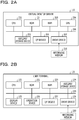
- FIG. 2A is a diagram illustrating one example of the hardware configuration of the virtual desktop server.
- the virtual desktop server 110 includes a central processing unit (CPU) 201, and a read only memory (ROM) 202.
- the virtual desktop server 110 also includes a random access memory (RAM) 203 and a graphics processing unit (GPU) 204.
- the CPU 201, the ROM 202, the RAM 203, and the GPU 204 constitute a so-called computer.
- the virtual desktop server 110 further includes an auxiliary storage device 205, an interface (I/F) device 206, and a drive device 207. Moreover, the hardware components of the virtual desktop server 110 are coupled to each other via a bus 208.
- the CPU 201 is a computation device that executes various programs (details will be described later) installed in the auxiliary storage device 205.
- the ROM 202 is a non-volatile memory and functions as a main storage device.
- the ROM 202 stores various programs, data, and so on, to be used by the CPU 201 to run the various programs installed in the auxiliary storage device 205.
- the ROM 202 stores a boot program and so on such as a Basic Input/Output System (BIOS) and an Extensible Firmware Interface (EFI).
- BIOS Basic Input/Output System
- EFI Extensible Firmware Interface
- the RAM 203 is a volatile memory such as a dynamic random access memory (DRAM) or a static random access memory (SRAM), and functions as a main storage device.
- the RAM 203 provides a work area on which the various programs installed in the auxiliary storage device 205 are expanded for execution by the CPU 201.
- the screen image is "input" in the example of FIG. 4 .
- the example of FIG. 4 indicates that frame images 441, 451, 461 and 471 are generated by the application 340 at respective times and input to the encoding unit.
- a decoded image acquired by decoding the frame image 461 subjected to the encoding processing (in this case, a decoded image 468 (the image 462 in the still-image region, an image in the video region, and the image 464 in the line-drawing region)) is held the buffer.
- the still-image encoder 410 outputs NULL data as a still-image stream 475.
- the information volume increases again (see reference number 802). It is because the video encoder 420 generates the video stream by encoding the entire frame image 461, and the line-drawing encoder generates the line-drawing stream by encoding the line-drawing region. Also at this time, since the image in the still-image region is not changed, the still-image stream has the information volume of zero.
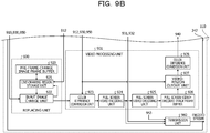
- the encoding unit 342 includes an update frequency determination unit 910, a region determination unit 911, and an encoding scheme determination unit 912, which constitute the determination unit 400.
- the encoding scheme determination unit 912 determines an encoding scheme based on the determination result in the region determination unit 911. In the first embodiment, the encoding scheme determination unit 912 determines that the entire frame image shall be encoded by the video encoder 420 when the video region is included in the frame image. In this case, the encoding scheme determination unit 912 notifies a color difference conversion unit 923 and a video-region cutout unit 927 of video region information.
- the encoding scheme determination unit 912 further determines whether or not both the video region and the line-drawing region are included in the frame image, and notifies a line-drawing region storage unit 921 of the determination result.
- the pre-frame-change image frame buffer 920 holds a frame image before being input to the video encoder 420 by a full screen video encoding unit 924. Specifically, the pre-frame-change image frame buffer 920 holds the frame image notified to the color difference conversion unit 923 by the input image change unit 922.
- the line-drawing region storage unit 921 refers to the frame image held in the pre-frame-change image frame buffer 920 when the encoding scheme determination unit 912 notifies of the determination result that both the video region and the line-drawing region are included in the input frame image.
- the line-drawing region storage unit 921 writes the post-replacing frame image, notified to the color difference conversion unit 923 by the input image change unit 922, in the pre-frame-change image frame buffer 920. Accordingly, the post-replacing frame image is held in the pre-frame-change image frame buffer 920.
- the encoding unit 342 includes the color difference conversion unit 923, the full screen video encoding unit 924, a full screen video decoding unit 925, a full screen video-decoded image frame buffer 926, a video-region cutout unit 927, and a color difference conversion unit 928, which constitute a video processing unit 901.
- the color difference conversion unit 923 operates when the video region information is notified by the encoding scheme determination unit 912. Specifically, the color difference conversion unit 923 converts color difference format of the frame image (the input frame image or the post-replacing frame image) notified by the input image change unit 922. Specifically, the color difference conversion unit 923 converts the color difference format from 4:4:4 format to 4:2:0 format.
- the full screen video encoding unit 924 allows the video encoder 420 to perform the video encoding on the entire frame image for the frame image converted by the color difference conversion unit 923 to the 4:2:0 format, thereby generating a video stream.
- the full screen video encoding unit 924 notifies the full screen video decoding unit 925 and a transmission unit 960 of the video stream generated by the video encoder 420.
- the color difference conversion unit 928 converts a color difference format of the image at the position of the video region, which is notified by the video-region cutout unit 927. Specifically, the color difference conversion unit 928 converts the color difference format from the 4:2:0 format to the 4:4:4 format.
- conversion from the 4:2:0 format to the 4:4:4 format means that a Y component is left without any change, a U component is thinned and interpolated so as to be two times each in vertical and horizontal directions, and a V component is thinned and interpolated so as to be two times each in the vertical and horizontal directions in the image at the position of the video region.
- the color difference conversion unit 928 notifies a client image frame buffer 940 of the image (video-decoded image) at the position of the video region acquired by converting the color difference format.
- the encoding unit 342 includes the line-drawing region extraction unit 930, a line-drawing encoding unit 931, and a line-drawing decoding unit 932, which constitute a line-drawing processing unit 902.
- the line-drawing region extraction unit 930 operates when the line-drawing region information is notified by the encoding scheme determination unit 912, and extracts an image in the line-drawing region specified by the line-drawing region information from the input frame image.
- the line-drawing encoding unit 931 allows the line-drawing encoder 430 to encode the image in the line-drawing region extracted by the line-drawing region extraction unit 930, thereby generating a line-drawing stream.
- the line-drawing encoder 430 generates the line-drawing stream with the encoding scheme, for example, chain encoding, directed delta encoding, sketch based coding (SBC), and so on.
- the encoding scheme used by the line-drawing encoder 430 to generate the line-drawing stream is not limited to chain encoding, directed delta encoding, and SBC.
- the line-drawing decoding unit 932 generates a line-drawing-decoded image by decoding the line-drawing stream notified by the line-drawing encoding unit 931. Further, the line-drawing decoding unit 932 notifies the client image frame buffer 940 of the generated line-drawing-decoded image.
- the client image frame buffer 940 holds the video-decoded image notified by the color difference conversion unit 928.
- the client image frame buffer 940 also holds the line-drawing-decoded image notified by the line-drawing decoding unit 932.
- the client image frame buffer 940 further holds a still-image-decoded image notified by a still-image decoding unit 954, which will be described later.
- the still-image difference calculation unit 951 generates a difference image for the image in the still-image region. Specifically, a still-image difference image is generated based on a difference between: - the still-image-decoded image of an immediately preceding frame image, which is stored in the client image frame buffer 940 and read by the still-image reference image acquisition unit 952; and - the image in the still-image region of the frame image to be processed, notified by the still-image region extraction unit 950. Further, the still-image difference calculation unit 951 notifies the still-image region encoding unit 953 of the generated the still-image difference image.
- the still-image decoding unit 954 generates a still-image-decoded image by decoding the still-image stream notified by the still-image region encoding unit 953. Further, the still-image decoding unit 954 notifies the client image frame buffer 940 of the generated still-image-decoded image.
- the transmission unit 960 transmits to the user terminal 120 the video stream notified by the full screen video encoding unit 924, the line-drawing stream notified by the line-drawing encoding unit 931, and the still-image stream notified by the still-image region encoding unit 953.
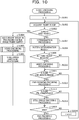
- the encoding unit 342 starts the encoding processing illustrated in FIG. 10 .
- step S1001 the determination unit 400 inputs "1" to a frame counter n.
- step S1004 the input image change unit 922 acquires the frame image, and the line-drawing region storage unit 921 writes acquired input frame image in the pre-frame-change image frame buffer 920. Accordingly, the frame image of the first frame is held in the pre-frame-change image frame buffer 920.
- step S1005 the video processing unit 901 executes the video encoding processing. Further, in step S1006, the still-image processing unit 903 executes the still-image encoding processing. Accordingly, the client image frame buffer 940 holds a decoded image acquired by executing the encoding processing on the frame image of the first frame and decoding the encoded image.
- the transmission unit 960 transmits a video-encoded stream and a still-image-encoded stream, acquired by executing the encoding processing on the frame image of the first frame.
- step S1003 when it is determined in step S1003 that the frame is not the first frame (n ⁇ 1) (NO in step S1003), the processing proceeds to step S1007.
- step S1007 the update frequency determination unit 910 and the region determination unit 911, of the determination unit 400, execute the determination processing.
- step S1008 the encoding scheme determination unit 912 of the determination unit 400 determines whether or not both the video region and the line-drawing region are included in the frame image of the n-th frame, and notifies the line-drawing region storage unit 921 of the replacing unit 600 of the determination result.
- step S1009 the encoding scheme determination unit 912 of the determination unit 400 determines whether or not the video region is included in the frame image of the n-th frame.
- step S1009 when it is determined that the video region is included (YES in step S1009), the video region information is notified to the color difference conversion unit 923 and the video-region cutout unit 927, and the processing proceeds to step S1010.
- step S1010 the video processing unit 901 performs the video encoding processing on the frame image of the n-th frame, and the processing proceeds to step S1011. Meanwhile, when it is determined in step S1009 that the video region is not included (NO in step S1009), the processing directly proceeds to step S1011.
- step S1011 the encoding scheme determination unit 912 of the determination unit 400 determines whether or not the line-drawing region is included in the frame image of the n-th frame. In step S1011, when it is determined that the line-drawing region is included (YES in step S1011), the line-drawing region information is notified to the line-drawing region extraction unit 930, and the processing proceeds to step S1012.
- step S1012 the line-drawing processing unit 902 executes the line-drawing encoding processing, and the processing proceeds to step S1013. Meanwhile, when it is determined in step S1011 that the line-drawing region is not included (NO in step S1011), the processing directly proceeds to step S1013.
- step S1013 the determination unit 400 determines whether or not the still-image region is included in the frame image of the n-th frame. In step S1013, when it is determined that the still-image region is included (YES in step S1013), the still-image region information is notified to the still-image region extraction unit 950, and the processing proceeds to step S1014.
- step S1014 the still-image processing unit 903 executes the still-image encoding processing, and the processing proceeds to step S1015. Meanwhile, when it is determined in step S1013 that the still-image region is not included (NO in step S1013), the processing directly proceeds to step S1015.
- step S1015 the determination unit 400 determines whether the encoding processing shall be ended or not. When it is determined in step S1015 that the encoding processing shall not be ended (NO in step S1015), the processing proceeds to step S1016. The frame counter n is incremented, and the processing returns to step S1002.
- step S1015 when it is determined in step S1015 that the encoding processing shall be ended (YES in step S1015), the encoding processing is ended.
- step S1005, S1006, S1007, S1010 and S1014) in the encoding processing illustrated in FIG. 10 will be described below.
- FIG. 11A is a first flowchart illustrating the details of each step in the encoding processing, which indicates the details of step S1005 (video encoding processing).
- the color difference conversion unit 923 converts the color difference format of the frame image of the first frame, acquired by the input image change unit 922, to the 4:2:0 format.
- step S1102 the full screen video encoding unit 924 allows the video encoder 420 to encode on the frame image of the first frame image with the converted color difference format, thereby generating a video stream. Further, the transmission unit 960 transmits the generated video stream.
- step S1103 the full screen video decoding unit 925 generates a full screen video-decoded image by decoding the video stream. Further, the color difference conversion unit 928 converts the color difference format of the generated full screen video-decoded image to the 4:4:4 format.
- step S1104 the color difference conversion unit 928 writes the full screen video-decoded image with the converted color difference format in the client image frame buffer 940.
- FIG. 11B is a second flowchart illustrating the details of each step in the encoding processing, which indicates the details of step S1006 (still-image encoding processing).
- step S1111 the still-image reference image acquisition unit 952 acquires the full screen video-decoded image which is held in the client image frame buffer 940 by performing the video encoding processing on the frame image of the first frame. Further, the still-image reference image acquisition unit 952 acquires an image in the still-image region from the acquired full screen video-decoded image.
- step S1113 the still-image region encoding unit 953 performs the still-image encoding on the generated difference image using the still-image encoder 410, thereby generating a still-image stream. Further, the transmission unit 960 transmits the generated still-image stream.
- step S1115 the still-image decoding unit 954 adds the decoded still-image stream to the image in the still-image region, acquired in step S1111, thereby generating a still-image-decoded image.
- FIG. 12A is a third flowchart illustrating the details of each step in the encoding processing, which indicates the details of step S1007 (determination processing).
- the update frequency determination unit 910 divides the input frame image into a plurality of regions, and calculates update frequency of each of divided regions.
- step S1203 the region determination unit 911 calculates the number of colors included in each of the divided regions, and determines that the divided region is the line-drawing region when the calculated number of colors is less than a predetermined threshold, but is not the line-drawing region when the calculated number of colors is equal to or more than the predetermined threshold.
- FIG. 12B is a fourth flowchart illustrating the details of each step in the encoding processing, which indicates the details of step S1010 (video encoding processing).
- step S1211 the line-drawing region storage unit 921 determines whether both the video region and the line-drawing region are included or not based on the determination result notified by the encoding scheme determination unit 912.
- step S1211 When it is determined in step S1211 that both the video region and the line-drawing region are included (YES in step S1211), the processing proceeds to step S1212.
- step S1211 the line-drawing region storage unit 921 refers to the pre-frame-change image frame buffer 920, and acquires an image in a region corresponding to a position of the line-drawing region included in a frame image of an (n-1)-th frame. Further, the line-drawing region storage unit 921 notifies the input image change unit 922 of the acquired image.
- step S1213 the input image change unit 922 acquires the frame image of the n-th frame, overwrites the image notified by line-drawing region storage unit 921 at the position of the line-drawing region, and notifies the video processing unit 901 of the overwritten frame image of the n-th frame.
- step S1211 when it is determined in step S1211 that both the video region and the line-drawing region are not included (NO in step S1211), the processing proceeds to step S1214.
- step S1214 the input image change unit 922 notifies the color difference conversion unit 923 of the video processing unit 901 of the frame image of the n-th frame without any change.
- step S1215 the color difference conversion unit 923 converts the color difference format of the frame image of the n-th frame, notified by the input image change unit 922, to the 4:2:0 format. Further, the full screen video encoding unit 924 allows the video encoder 420 to perform the video encoding on the entire frame image for the frame image converted to the 4:2:0 format, thereby generating a video stream.
- step S1216 the transmission unit 960 transmits the generated video stream to the user terminal 120.
- step S1217 the full screen video decoding unit 925 generates a full screen video-decoded image by decoding the video stream. Further, the video-region cutout unit 907 cuts out an image at a position of the video region from the full screen video-decoded image, based on the video region information notified by the encoding scheme determination unit 912. The color difference conversion unit 928 converts the color difference format of the cut-out image at the position of the video region to the 4:4:4 format, thereby generating a video-decoded image.
- step S1218 the color difference conversion unit 928 writes the generated video-decoded image in the client image frame buffer 940.
- step S1219 the line-drawing region storage unit 921 acquires the frame image of the n-th frame, notified by the input image change unit 922 to the video processing unit 901 in step S1213 or step S1214.
- step S1220 the line-drawing region storage unit 921 writes the acquired frame image of the n-th frame in the pre-frame-change image frame buffer 920.
- FIG. 13 is a fifth flowchart illustrating the details of each step in the encoding processing.
- step S1301 the still-image reference image acquisition unit 952 acquires the still-image-decoded image corresponding to the frame image of the (n-1)-th frame from the client image frame buffer 940.
- step S1302 the still-image region extraction unit 950 extracts an image in the still-image region from the frame image of the n-th frame based on the still-image region information notified by the encoding scheme determination unit 912. Further, the still-image difference calculation unit 951 generates a still-image difference image from difference between the extracted image in the still-image region from the frame image of the n-th frame and the still-image-decoded image corresponding to the frame image of the (n-1)-th frame.
- step S1303 the still-image region encoding unit 953 performs the still-image encoding on the still-image difference image using the still-image encoder 410, thereby generating a still-image stream.
- step S1305 the still-image decoding unit 954 decodes the still-image stream.
- step S1306 the still-image decoding unit 954 adds the decoded still-image stream to the still-image-decoded image corresponding to the frame image of the (n-1)-th frame, thereby generating a still-image-decoded image corresponding to the frame image of the n-th frame.
- step S1307 the still-image decoding unit 954 writes the still-image-decoded image corresponding to the frame image of the n-th frame in the client image frame buffer 940.
- FIG. 14 is a diagram illustrating the outline of the decoding processing by the user terminal.
- encoded streams illustrated in "input" column indicate the encoded streams received at each time.
- the still-image stream 442 is a still-image stream which is generated by the virtual desktop server 110 based on the frame image 441 at the time T1 and transmitted.
- the still-image stream 452 is a still-image stream which is generated by the virtual desktop server 110 based on the frame image 451 at the time T2 and transmitted.
- the still-image stream 465, the video stream 612, and the line-drawing stream 467 are respectively a still-image stream, a video stream, and a line-drawing stream, which are generated by the virtual desktop server 110 based on the frame image 461 at the time T3 and transmitted.
- the still-image stream 475, the video stream 712, and the line-drawing stream 477 are respectively a still-image stream, a video stream, and a line-drawing stream, which are generated by the virtual desktop server 110 based on the frame image 471 at the time T4 and transmitted. Therefore, the reference symbols ("A", "B", "a” and "b") indicated in FIG. 14 are the same as those in FIGs. 6 and 7 .
- the decoding unit 351 receives the still-image stream 442, and a still-image decoder 1410 decodes the still-image stream 442.
- a still-image-decoded image 1442 is displayed on the user terminal 120.
- the decoding unit 351 the still-image-decoded image 1442 is held in a buffer.
- the still-image stream 452 received by the decoding unit 351 is the NULL data. Accordingly, the still-image-decoded image 1442 held in the buffer is added to a still-image-decoded image 1452 decoded by the still-image decoder 1410 to output the still-image-decoded image 1442. Thus, the still-image-decoded image 1442 is displayed on the user terminal 120. In the decoding unit 351, the still-image-decoded image 1442 is held in a buffer.
- the decoding unit 351 receives the still-image stream 465, the video stream 612, and the line-drawing stream 467.
- the still-image stream 465 is decoded by the still-image decoder 1410.
- An image in the corresponding region of the still-image-decoded image 1442 held in the buffer is added to the decoded still-image stream, thereby generating a still-image-decoded image. Since the still-image stream 465 is the NULL data, the generated still-image-decoded image is equivalent to the image in the corresponding region of the still-image-decoded image 1442.
- the video stream 612 is decoded by a video decoder 1420 to generate a video-decoded image 1464.
- the line-drawing stream 467 is decoded by a line-drawing decoder 1430 to generate a line-drawing-decoded image 1465.
- a decoded image 1466 is generated and displayed by adding the generated video-decoded image 1464 and the generated line-drawing-decoded image 1465 to the still-image-decoded image.
- the generated decoded image 1466 is held in the buffer.
- the decoding unit 351 receives the still-image stream 475, the video stream 712, and the line-drawing stream 477.
- the still-image stream 475 is decoded by the still-image decoder 1410.
- An image in the corresponding region of the decoded image 1466 held in the buffer is added to the decoded still-image stream, thereby generating a still-image-decoded image. Since the still-image stream 475 is the NULL data, the generated still-image-decoded image is equivalent to the image in the corresponding region of the decoded image 1466.
- the video stream 712 is decoded by a video decoder 1420 to generate a video-decoded image 1474.
- the line-drawing stream 477 is decoded by a line-drawing decoder 1430 to generate a line-drawing-decoded image 1475.
- a decoded image 1476 is generated and displayed by adding the generated video-decoded image 1474 and the generated line-drawing-decoded image 1475 to the still-image-decoded image.
- the generated decoded image 1476 is held in the buffer.
- FIG. 15 is a diagram illustrating one example of a function configuration of the decoding unit of the user terminal.
- a receiving unit 1511 receives an encoded stream for each frame from the virtual desktop server 110, and notifies a changed-region acquisition unit 1512 of the received encoded stream.
- the changed-region acquisition unit 1512 acquires the video region information and the still-image region information and notifies an encoding scheme acquisition unit 1513 of the information.
- the video encoder and the line-drawing encoder are able to avoid to encode the same line-drawing region even when the video region and the line-drawing region are included in the frame image.
Landscapes
- Engineering & Computer Science (AREA)
- Multimedia (AREA)
- Signal Processing (AREA)
- Computing Systems (AREA)
- Theoretical Computer Science (AREA)
- Physics & Mathematics (AREA)
- Discrete Mathematics (AREA)
- General Physics & Mathematics (AREA)
- Compression Or Coding Systems Of Tv Signals (AREA)
Abstract
Description
- The embodiments discussed herein are related to an encoding technology.
- A screen transfer processing for transferring an encoded screen image has carried out by various encoders including a video encoder capable of encoding a video and a line-drawing encoder suitable for encoding a line drawing such as CAD images, for several years, properly depending on a type of the screen image.
- In video encoding with high compression performance, such as H. 264 or High Efficiency Video Coding (HEVC), processing load on the encoding is significantly high because of the complex processing. Accordingly, in a case where the processing is required to be carried out in real time, the video encoder is generally often implemented by a dedicated hardware. A video hardware encoder encodes a video frame by frame, thus even when a region other than the video is included in a frame image (for example, the frame image includes a video region and a line-drawing region), a video stream is generated for the entire frame image.
- Meanwhile, the line-drawing encoder implemented by software is capable of generating a line-drawing stream by extracting the line-drawing region. Consequently, on a side of a decoding device, for example, a line drawing acquired by decoding the line-drawing stream is overwritten at a position of the line-drawing region in the frame image acquired by decoding the video stream, thereby generating the screen image.
- For example, related arts are disclosed in Japanese Laid-open Patent Publication Nos.
2-44883 2000-57354 - When the screen transfer processing as described above is performed, the video encoder and the line-drawing encoder encode the same line-drawing region in the frame image, thus the line-drawing region is transferred to the decoding device. Therefore, information volume of an encoded stream increases.
- According to an aspect of the embodiments, an encoding device includes an encoding unit configured to extract a first line-drawing region from a first image in a plurality of images, by replacing the first line-drawing region of the first image with an image which is included in a second image preceding the first image in the plurality of images and corresponds to the first line-drawing region, generate a third image, generate video encoding information by performing a video encoding processing based on the third image, generate line-drawing encoding information by performing a line-drawing encoding processing based on the first line-drawing region, and transmit the video encoding information and the line-drawing encoding information to a decoding device.
- The present disclosure is made to suppress increase in the information volume upon encoding the frame image including the video region and the line-drawing region.
- It is to be understood that both the foregoing general description and the following detailed description are exemplary, and are intended to provide further explanation of the invention as claimed. Other advantages and features of the invention will be apparent from the following description, drawings and claims.
-
-
FIG. 1 is a diagram illustrating one example of a system configuration of a screen transfer system; -
FIG. 2A is a diagram illustrating one example of a hardware configuration of a virtual desktop server; -
FIG. 2B is a diagram illustrating one example of a hardware configuration of a user terminal; -
FIG. 3A is a diagram illustrating one example of a software configuration of the virtual desktop server; -
FIG. 3B is a diagram illustrating one example of a software configuration of the user terminal; -
FIG. 4 is a diagram illustrating an outline of an encoding processing by a server of a comparative example; -
FIG. 5 is a diagram illustrating information volume of an encoded stream generated in the encoding processing by the server of the comparative example; -
FIG. 6 is a first diagram illustrating an outline of an encoding processing by the virtual desktop server; -
FIG. 7 is a second diagram illustrating the outline of the encoding processing by the virtual desktop server; -
FIG. 8 is a diagram illustrating information volume of an encoded stream generated in the encoding processing by the virtual desktop server; -
FIGs. 9A and9B are diagrams illustrating one example of a function configuration of an encoding unit of the virtual desktop server; -
FIG. 10 is a flowchart illustrating a flow of the encoding processing by the virtual desktop server; -
FIG. 11A is a first flowchart illustrating the details of each step in the encoding processing; -
FIG. 11B is a second flowchart illustrating the details of each step in the encoding processing; -
FIG. 12A is a third flowchart illustrating the details of each step in the encoding processing; -
FIG. 12B is a fourth flowchart illustrating the details of each step in the encoding processing; -
FIG. 13 is a fifth flowchart illustrating the details of each step in the encoding processing; -
FIG. 14 is a diagram illustrating an outline of a decoding processing by the user terminal. -
FIG. 15 is a diagram illustrating one example of a function configuration of a decoding unit of the user terminal; -
FIG. 16 is a flowchart illustrating a flow of the decoding processing by the user terminal; -
FIG. 17A is a first flowchart illustrating the details of each step in the decoding processing; -
FIG. 17B is a second flowchart illustrating the details of each step in the decoding processing; -
FIG. 18A is a third flowchart illustrating the details of each step in the decoding processing; and -
FIG. 18B is a fourth flowchart illustrating the details of each step in the decoding processing. - Hereinafter, the embodiments of the present disclosure are described with reference to the accompanying drawings. In the specification and drawings, constituent elements having substantially the same functional configuration are described with the same reference sign and the overlapping description thereof is omitted.
- First, description is provided for a system configuration of a screen transfer system employing an encoding device according to a first embodiment.
FIG. 1 is a diagram illustrating one example of the system configuration of the screen transfer system. - As illustrated in
FIG. 1 , ascreen transfer system 100 includes avirtual desktop server 110 which is an encoding device according to the first embodiment, and auser terminal 120 which is communicably connected to thevirtual desktop server 110. - The
virtual desktop server 110 encodes an image of a screen (screen image) generated by executing various applications, and transmits an encoded stream to the user terminal. Accordingly, theuser terminal 120 decodes the encoded stream received from the server and displays the screen image. - The
virtual desktop server 110 receives operation information from theuser terminal 120 in a case where a user operates theuser terminal 120 and inputs various instructions to the applications in response to the transmission of the encoded stream. - By using the
virtual desktop server 110 with a screen transfer function, the user does not have to store data in the user terminal when executing the various applications. With thescreen transfer system 100, it is possible to inhibit information leakage from theuser terminal 120 and to enhance security. - A hardware configuration of each device (the
virtual desktop server 110 and the user terminal 120) of thescreen transfer system 100 will be described below.FIG. 2A is a diagram illustrating one example of the hardware configuration of the virtual desktop server. - As illustrated in
FIG. 2A , thevirtual desktop server 110 includes a central processing unit (CPU) 201, and a read only memory (ROM) 202. Thevirtual desktop server 110 also includes a random access memory (RAM) 203 and a graphics processing unit (GPU) 204. TheCPU 201, the ROM 202, theRAM 203, and theGPU 204 constitute a so-called computer. - The
virtual desktop server 110 further includes anauxiliary storage device 205, an interface (I/F)device 206, and adrive device 207. Moreover, the hardware components of thevirtual desktop server 110 are coupled to each other via abus 208. - The
CPU 201 is a computation device that executes various programs (details will be described later) installed in theauxiliary storage device 205. - The ROM 202 is a non-volatile memory and functions as a main storage device. The ROM 202 stores various programs, data, and so on, to be used by the
CPU 201 to run the various programs installed in theauxiliary storage device 205. Specifically, the ROM 202 stores a boot program and so on such as a Basic Input/Output System (BIOS) and an Extensible Firmware Interface (EFI). - The
RAM 203 is a volatile memory such as a dynamic random access memory (DRAM) or a static random access memory (SRAM), and functions as a main storage device. TheRAM 203 provides a work area on which the various programs installed in theauxiliary storage device 205 are expanded for execution by theCPU 201. - The
GPU 204 is a computation device for image processing, and performs high-speed computation by parallel processing on various images when theCPU 201 executes the various programs. In the first embodiment, a video encoder is implemented by theGPU 204. - The
auxiliary storage device 205 stores the various programs and information to be used when theCPU 201 executes the various programs. The I/F device 206 is a coupling device which is coupled to and communicates with the other devices (for example, the user terminal 120). - The
drive device 207 is a device in which arecording medium 210 is set. Therecording media 210 discussed herein include media which record information optically, electrically, and magnetically like a CD-ROM, a flexible disk, a magnetooptical disk, and so forth. In addition, therecording media 210 may also include a semiconductor memory and so on, such as a ROM and a flash memory, which record information electrically. - The various programs installed in the
auxiliary storage device 205 are installed, for example, in such a way that a distributedrecording medium 210 is set in thedrive device 207, and the various programs recorded in therecording medium 210 is read by thedrive device 207. Alternatively, the various programs installed in theauxiliary storage device 205 may be installed by downloading the programs from a network (omitted). -
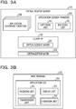
FIG. 2B is a diagram illustrating one example of the hardware configuration of the user terminal. Difference betweenFIGs. 2A and 2B is that adisplay device 225 and anoperation device 226 are provided but theGPU 204 is not provided in the example ofFIG. 2B . Therefore, thedisplay device 225 and theoperation device 226 will be described herein. - The
display device 225 is a display device which displays the screen image transmitted from thevirtual desktop server 110 and decoded by theuser terminal 120. Theoperation device 226 is an operation device to be used by the user of theuser terminal 120 to input various instructions. - A software configuration of each device (the
virtual desktop server 110 and the user terminal 120) of thescreen transfer system 100 will be described below.FIG. 3A is a diagram illustrating one example of the software configuration of the virtual desktop server. - As illustrated in
FIG. 3A , thevirtual desktop server 110 includes avirtualization layer 310, a client operation system (OS) 320, anapplication 330, and anapplication 340. - The
virtualization layer 310 is a software which virtualizes thevirtual desktop server 110, and allows a plurality of OSs to share and use resources possessed by thevirtual desktop server 110. - The
client OS 320 is a guest operating system (OS) operating on thevirtualization layer 310. Theclient OS 320 includes avirtual display driver 321, in which the screen image generated by theapplication 330 is written during execution of theapplication 330. - The
application 330 is a software used by the user of theuser terminal 120. A document creation software is illustrated in the example ofFIG. 3A ; however, the software executed on thevirtual desktop server 110 is not limited to the document creation software. A random software is assumed to be executed on thevirtual desktop server 110. - The
application 340 is a software for screen transfer, which includes acapturing unit 341 and anencoding unit 342. The capturingunit 341 captures the screen image written in thevirtual display driver 321. Theencoding unit 342 encodes the screen image captured by the capturingunit 341, and transmits the encoded stream to theuser terminal 120. -
FIG. 3B is a diagram illustrating one example of the software configuration of the user terminal. As illustrated inFIG. 3B , theuser terminal 120 includes anapplication 350 for user interface (UI). - The
application 350 includes adecoding unit 351, adisplay unit 352, atransmission unit 353, and anoperation unit 354. Thedecoding unit 351 generates the screen image by decoding encoded data transmitted from thevirtual desktop server 110 and notifies thedisplay unit 352 of the screen image. Thedisplay unit 352 controls to display the notified screen image on thedisplay device 225 of theuser terminal 120. - The
operation unit 354 receives instructions in a case where the user of theuser terminal 120 inputs the instructions to theapplication 330 via theoperation device 226 in response to the screen image displayed on thedisplay device 225. Thetransmission unit 353 transmits the instructions received by theoperation unit 354 to thevirtual desktop server 110 as operation information. - The encoding processing by the
virtual desktop server 110 will be described. Further, a server of a comparative example will be described first in order to describe the encoding processing by thevirtual desktop server 110. The outline of the encoding processing by the server of the comparative example will be described, and then information volume of an encoded stream generated by the server of the comparative example will be described. Thereafter, the outline of the encoding processing by thevirtual desktop server 110 and information volume of the encoded stream generated by thevirtual desktop server 110 will be described. -
FIG. 4 is a diagram illustrating an outline of the encoding processing by the server of the comparative example. As illustrated inFIG. 4 , the server of the comparative example includes adetermination unit 400, a still-image encoder 410, avideo encoder 420, and a line-drawingencoder 430. - In the server of the comparative example, when the screen image is input to the encoding unit, the
determination unit 400 determines whether or not there is a still-image region, a video region, or a line-drawing region for each frame image. The still-image encoder 410 performs still-image encoding on an image in the still-image region to generate a still-image stream (still-image encoded information) for each frame image. Thevideo encoder 420 performs video encoding on the entire frame image to generate a video stream (video encoding information). Further, the line-drawingencoder 430 performs line-drawing encoding on an image in the line-drawing region to generate a line-drawing stream (line-drawing encoding information). - The screen image is "input" in the example of
FIG. 4 . The example ofFIG. 4 indicates thatframe images application 340 at respective times and input to the encoding unit. - Blank regions in the
frame images frame images frame images - When the
frame image 441 is input at a time T1, thedetermination unit 400 determines that theframe image 441 includes the still-image region. The still-image encoder 410 performs the still-image encoding on an image in the still-image region of the frame image 441 (that is, the frame image 441) to generate and output a still-image stream 442. At this time, a decoded image acquired by decoding theframe image 441 subjected to the encoding processing (in this case, a decoded image 443 (the same as the frame image 441) acquired by decoding the still-image stream 442) is held in a buffer. - When the
frame image 451 is input at a time T2, thedetermination unit 400 determines that theframe image 451 includes the still-image region. Difference between the decoded image 443 (its image of the still-image region) held in the buffer and the image in the still-image region of the frame image 451 (that is, the frame image 451) is calculated, and then a still-image difference image is input to the still-image encoder 410. - The image in the still-image region is not changed, thus the
frame image 451 is the same as theframe image 441. As described above, the decodedimage 443 held in the buffer is the same as theframe image 441. Therefore, the still-image difference image acquired from the difference between the decodedimage 443 and theframe image 451 is zero, thus the still-image encoder 410 outputs NULL data as a still-image stream 452. At this time, a decoded image acquired by decoding theframe image 451 subjected to the encoding processing (in this case, the decoded image 443 (the same as the frame image 441)) is held the buffer. - When the
frame image 461 is input at a time T3, thedetermination unit 400 determines that theframe image 461 includes the still-image region. Consequently, a still-image difference image acquired from difference between an image 462 in the still-image region and an image at a position corresponding to a position of the still-image region of the decodedimage 443 held in the buffer, is input to the still-image encoder 410. - Since the image in the still-image region is not changed, the still-image difference image has the information volume of zero, thus the still-
image encoder 410 outputs NULL data as a still-image stream 465. - Further, when the
frame image 461 is input at the time T3, thedetermination unit 400 determines that theframe image 461 includes the video region. Therefore, the entire frame image 463 (that is, the frame image 461) is input to thevideo encoder 420. Consequently, thevideo encoder 420 performs the video encoding on theentire frame image 463 to generate a video stream 466. - Further, when the
frame image 461 is input at the time T3, thedetermination unit 400 determines that theframe image 461 includes the line-drawing region. Therefore, animage 464 in the line-drawing region is input to the line-drawingencoder 430. Consequently, the line-drawingencoder 430 performs the line-drawing encoding on theimage 464 in the line-drawing region of theframe image 461 to generate and output a line-drawing stream 467. - A decoded image acquired by decoding the
frame image 461 subjected to the encoding processing (in this case, a decoded image 468 (the image 462 in the still-image region, an image in the video region, and theimage 464 in the line-drawing region)) is held the buffer. - When the
frame image 471 is input at a time T4, thedetermination unit 400 determines that theframe image 471 includes the still-image region. Consequently, the still-image difference image acquired from difference between theimage 472 in the still-image region and an image at a position corresponding to a position of the still-image region of the decodedimage 468 held in the buffer, is input to the still-image encoder 410. - Since the still-image region is not changed, the still-image difference image has the information volume of zero, thus the still-
image encoder 410 outputs NULL data as a still-image stream 475. - Further, when the
frame image 471 is input at the time T4, thedetermination unit 400 determines that theframe image 471 includes the video region. Therefore, a frame image 473 (that is, the frame image 471) is input to thevideo encoder 420. Consequently, thevideo encoder 420 performs the video encoding on the frame image 473 to generate avideo stream 476. - Further, when the
frame image 471 is input at the time T4, thedetermination unit 400 determines that theframe image 471 includes the line-drawing region. Therefore, animage 474 in the line-drawing region is input to the line-drawingencoder 430. Consequently, the line-drawingencoder 430 performs the line-drawing encoding on theimage 474 in the line-drawing region of theframe image 471 to generate and output a line-drawing stream 477. - A decoded image acquired by decoding the
frame image 471 subjected to the encoding processing (in this case, a decoded image 478 (theimage 472 in the still-image region, an image in the video region, and theimage 474 in the line-drawing region)) is held in the buffer. -
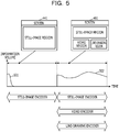
FIG. 5 is a diagram illustrating information volume of the encoded stream generated in the encoding processing by the server of the comparative example. A horizontal axis is the time, and a vertical axis is the information volume. - As illustrated in
FIG. 5 , in a case of the server of the comparative example, the still-image encoder 410 performs the still-image encoding on the image in the still-image region to generate the still-image stream 442 immediately after theframe image 441 of the screen image is generated, whereby the information volume is increased (see reference number 501). - On the other hand, in the server of the comparative example, the still-
image encoder 410 subsequently encodes the difference between the decoded image held in the buffer and the image in the still-image region. Therefore, when the frame image in which the entire frame image is the still-image region continues, the still-image stream has the information volume of zero. - When a predetermined time has elapsed and the
frame image 461 is generated, the information volume increases again (see reference number 502). It is because thevideo encoder 420 generates the video stream by encoding theentire frame image 461, and the line-drawing encoder generates the line-drawing stream by encoding the line-drawing region. Also at this time, since the image in the still-image region is not changed, the still-image stream has the information volume of zero. - Further, even after the
frame image 461 is generated, the image in the video region and the image in the line-drawing region change with time. Therefore, the video stream generated by performing the video encoding on the entire frame image with thevideo encoder 420 has a certain extent of information volume. Similarly, the line-drawing stream generated by performing the line-drawing encoding on the image in the line-drawing region with the line-drawingencoder 430 has a certain extent of information volume. Consequently, even after theframe image 461 is generated, the information volume of the encoded stream generated in the encoding processing by the server of the comparative example is maintained high (see reference number 502). - The encoding processing by the
virtual desktop server 110 will be described.FIGs. 6 and7 are first and second diagrams respectively illustrating the outline of the encoding processing by the virtual desktop server. - The screen image is "input" in the examples of
FIGs. 6 and7 . The examples ofFIGs. 6 and7 indicate thatframe images application 340 at respective times and input to the encoding unit. SinceFIGs. 6 and7 illustrate the continuous encoding processing,FIG. 7 redundantly illustrates the encoding processing at the time T3 inFIG. 6 . - Further, the details of the encoding processing for the frame images input at the times T1 and T2 in the encoding processing illustrated in
FIG. 6 are the same as the details of the encoding processing for the frame images input at the times T1 and T2 in the encoding processing illustrated inFIG. 4 . Therefore, the descriptions for the same details are omitted, and the encoding processing after the time T3 will be described below. - Provided that the
encoding unit 342 of thevirtual desktop server 110 holds the decodedimage 443 acquired by decoding theframe image 441 subjected to the encoding processing in the buffer, and also holds the frame image immediately before being input to thevideo encoder 420 in the other buffer. In a case ofFIG. 6 , since theframe images video encoder 420, theframe images frame image 601. - When the
frame image 461 is input at the time T3, thedetermination unit 400 determines that theframe image 461 includes the still-image region. Consequently, a still-image difference image acquired from difference between an image 462 in the still-image region and an image at a position corresponding to a position of the still-image region of the decodedimage 443 held in the buffer, is input to the still-image encoder 410. - Since the image in the still-image region is not changed, the still-image difference image has the information volume of zero, thus the still-
image encoder 410 outputs NULL data as a still-image stream 465. - Further, when the
frame image 461 is input at the time T3, thedetermination unit 400 determines whether there is the video region or not and whether there is the line-drawing region or not. When it is determined that the video region and the line-drawing region are both included in theframe image 461, a replacingunit 600 replaces the image in the line-drawing region of the frame image 463 (that is, the frame image 461) with an image at a position corresponding to aframe image 601 held in the buffer. Accordingly, the replacingunit 600 generates apost-replacing frame image 611. Further, thevideo encoder 420 performs the video encoding on theentire frame image 611 to generate avideo stream 612. - The
post-replacing frame image 611 generated by the replacingunit 600 includes the video region and the still-image region, but no line-drawing region. Consequently, thevideo encoder 420 does not perform the video encoding on the image in the line-drawing region. The image in the still-image region of thepost-replacing frame image 611 does not change from the image in the still-image region in the immediately precedingframe image 451. Consequently, even when thevideo encoder 420 performs the video encoding on the image in the still-image region of thepost-replacing frame image 611, the information volume does not increase. - Accordingly, the information volume of the
video stream 612 generated by performing the video encoding on thepost-replacing frame image 611 with thevideo encoder 420 is the same as the information volume of the video stream in which only the image in the video region is encoded. - Further, the decoded
image 468 acquired by decoding theframe image 461 subjected to the encoding processing is held in the buffer. Theframe image 611 immediately before being input to thevideo encoder 420 is held in the other buffer as aframe image 613. - As illustrated in
FIG. 7 , when theframe image 471 is input at the time T4, thedetermination unit 400 determines that theframe image 471 includes the still-image region. Consequently, the still-image difference image acquired from difference between theimage 472 in the still-image region and an image at a position corresponding to a position of the still-image region of the decodedimage 468 held in the buffer, is input to the still-image encoder 410. - Since the still-image region is not changed, the still-image difference image has the information volume of zero, thus the still-
image encoder 410 outputs NULL data as a still-image stream 475. - Further, when the
frame image 471 is input at the time T4, thedetermination unit 400 determines whether there is the video region or not and whether there is the line-drawing region or not. When it is determined that the video region and the line-drawing region are both included in theframe image 471, a replacingunit 600 replaces the image in the line-drawing region of the frame image 473 (that is, the frame image 471) with an image at a position corresponding to aframe image 613 held in the buffer. Accordingly, the replacingunit 600 generates a post-replacing frame image 711. Further, thevideo encoder 420 performs the video encoding on the entire frame image 711 to generate avideo stream 712. - The post-replacing frame image 711 generated by the replacing
unit 600 includes the video region and the still-image region, but no line-drawing region. Consequently, thevideo encoder 420 does not perform the video encoding on the image in the line-drawing region. The image in the still-image region of the post-replacing frame image 711 does not change from the image in the still-image region in the immediately precedingframe image 461. Consequently, even when thevideo encoder 420 performs the video encoding on the image in the still-image region of the post-replacing frame image 711, the information volume does not increase. - Accordingly, the information volume of the
video stream 712 generated by performing the video encoding on the post-replacing frame image 711 with thevideo encoder 420 is the same as the information volume of the video stream in which only the image in the video region is encoded. - Further, the decoded image 478 acquired by decoding the
frame image 471 subjected to the encoding processing is held in the buffer. The frame image 711 immediately before being input to thevideo encoder 420 is held in the other buffer as a frame image 713. -
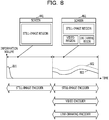
FIG. 8 is a diagram illustrating the information volume of the encoded stream generated in the encoding processing by the virtual desktop server. A horizontal axis is the time, and a vertical axis is the information volume, similar toFIG. 5 . - As illustrated in
FIG. 8 , in a case of thevirtual desktop server 110, the still-image encoder 410 performs the still-image encoding on the still-image region to generate the still-image stream 442 immediately after theframe image 441 of the screen image is generated, whereby the information volume is increased (see reference number 801). - On the other hand, in the
virtual desktop server 110, the still-image encoder 410 subsequently encodes the difference between the decoded image held in the buffer and the image in the still-image region. Therefore, when the frame image in which the entire frame image is the still-image region continues, the still-image stream has the information volume of zero. - When a predetermined time has elapsed and the
frame image 461 is generated, the information volume increases again (see reference number 802). It is because thevideo encoder 420 generates the video stream by encoding theentire frame image 461, and the line-drawing encoder generates the line-drawing stream by encoding the line-drawing region. Also at this time, since the image in the still-image region is not changed, the still-image stream has the information volume of zero. - Further, even after the
frame image 461 is generated, the image in the video region and the image in the line-drawing region change with time. Therefore, the video stream generated by performing the video encoding on the entire frame image with thevideo encoder 420 has a certain extent of information volume. Similarly, the line-drawing stream generated by performing the line-drawing encoding on the image in the line-drawing region with the line-drawingencoder 430 has a certain extent of information volume. Provided that, in a case of thevirtual desktop server 110, thevideo encoder 420 does not perform the video encoding on the image in the line-drawing region upon performing the video encoding on the entire frame image, as described above. In other words, thevideo encoder 420 and the line-drawingencoder 430 do not encode the same image in the line-drawing region. Since the image in the line-drawing region is replaced with the image in the still-image region before the line-drawing region is generated, the information volume does not increase even when thevideo encoder 420 performs the video encoding. - Accordingly, the information volume after the
frame image 461 is generated is suppressed compared with the example ofFIG. 5 (seereference numbers 502 and 802). - A functional configuration of the
encoding unit 342 for implementing the encoding processing described above will be described below.FIGs. 9A and9B are diagrams illustrating one example of the function configuration of the encoding unit of the virtual desktop server, which is implemented by executing an encoding program included in theapplication 340. - As illustrated in
FIGs. 9A and9B , theencoding unit 342 includes an update frequency determination unit 910, a region determination unit 911, and an encodingscheme determination unit 912, which constitute thedetermination unit 400. - The update frequency determination unit 910 acquires the screen image for each frame, and divides the acquired frame image into regions of a predetermined size (for example, 16 pixels × 16 pixels). Further, the update frequency determination unit 910 calculates an update frequency for each of the divided regions, and determines that the divided region is the video region when the calculated update frequency is equal to or more than a predetermined threshold, but is the still-image region when the calculated update frequency is less than the predetermined threshold.
- The region determination unit 911 calculates the number of colors included in each of the divided regions, and determines that the divided region is the line-drawing region when the calculated number of colors is less than a predetermined threshold, but is not the line-drawing region when the calculated number of colors is equal to or more than the predetermined threshold. Consequently, the region determination unit 911 is capable of determining whether each of divided regions is one of the followings: - the divided region is the still-image region and the line-drawing region; - the divided region is the still-image region but not the line-drawing region; - the divided region is the video region and the line-drawing region; and - the divided region is the video region but not the line-drawing region.
- The encoding
scheme determination unit 912 determines an encoding scheme based on the determination result in the region determination unit 911. In the first embodiment, the encodingscheme determination unit 912 determines that the entire frame image shall be encoded by thevideo encoder 420 when the video region is included in the frame image. In this case, the encodingscheme determination unit 912 notifies a colordifference conversion unit 923 and a video-region cutout unit 927 of video region information. - In the first embodiment, the encoding
scheme determination unit 912 determines that, when the line-drawing region is included in the frame image, the line-drawing region shall be encoded by the line-drawingencoder 430 and notifies a line-drawingregion extraction unit 930 of line-drawing region information. - Further, in the first embodiment, the encoding
scheme determination unit 912 determines that, when the still-image region is included in the frame image, the still-image region shall be encoded by the still-image encoder 410 and notifies a still-image region extraction unit 950 of still-image region information. - The encoding
scheme determination unit 912 further determines whether or not both the video region and the line-drawing region are included in the frame image, and notifies a line-drawingregion storage unit 921 of the determination result. - As illustrated in
FIGs. 9A and9B , theencoding unit 342 includes a pre-frame-changeimage frame buffer 920, the line-drawingregion storage unit 921, and an inputimage change unit 922, which constitute the replacingunit 600. - The pre-frame-change
image frame buffer 920 holds a frame image before being input to thevideo encoder 420 by a full screen video encoding unit 924. Specifically, the pre-frame-changeimage frame buffer 920 holds the frame image notified to the colordifference conversion unit 923 by the inputimage change unit 922. - The line-drawing
region storage unit 921 refers to the frame image held in the pre-frame-changeimage frame buffer 920 when the encodingscheme determination unit 912 notifies of the determination result that both the video region and the line-drawing region are included in the input frame image. - Further, the line-drawing
region storage unit 921 extracts an image at a position corresponding to the line-drawing region in the input frame image from the frame image held in the pre-frame-changeimage frame buffer 920, and notifies the inputimage change unit 922 of the extracted image. Accordingly, the inputimage change unit 922 replaces the image in the line-drawing region of the input frame image, with the image notified by the line-drawingregion storage unit 921, and notifies the colordifference conversion unit 923 of the post-replacing frame image. - Further, the line-drawing
region storage unit 921 writes the post-replacing frame image, notified to the colordifference conversion unit 923 by the inputimage change unit 922, in the pre-frame-changeimage frame buffer 920. Accordingly, the post-replacing frame image is held in the pre-frame-changeimage frame buffer 920. - Meanwhile, when the encoding
scheme determination unit 912 notifies of the determination result that the video region or the line-drawing region is not included in the frame image (the determination result that the video region is not included or the line-drawing region is not included), the frame image is notified to the inputimage change unit 922. In this case, the inputimage change unit 922 notifies the colordifference conversion unit 923 of the input frame image without any change. - Further, the line-drawing
region storage unit 921 writes the input frame image, notified to the colordifference conversion unit 923 by the inputimage change unit 922, in the pre-frame-changeimage frame buffer 920. Accordingly, the input frame image is held in the pre-frame-changeimage frame buffer 920. - As illustrated in
FIGs. 9A and9B , theencoding unit 342 includes the colordifference conversion unit 923, the full screen video encoding unit 924, a full screenvideo decoding unit 925, a full screen video-decodedimage frame buffer 926, a video-region cutout unit 927, and a colordifference conversion unit 928, which constitute avideo processing unit 901. - The color
difference conversion unit 923 operates when the video region information is notified by the encodingscheme determination unit 912. Specifically, the colordifference conversion unit 923 converts color difference format of the frame image (the input frame image or the post-replacing frame image) notified by the inputimage change unit 922. Specifically, the colordifference conversion unit 923 converts the color difference format from 4:4:4 format to 4:2:0 format. - Further, conversion from the 4:4:4 format to the 4:2:0 format means that a Y component is left without any change, a U component is thinned so as to be 1/2 times each in vertical and horizontal directions, and a V component is thinned so as to be 1/2 times each in the vertical and horizontal directions in the frame image.
- The full screen video encoding unit 924 allows the
video encoder 420 to perform the video encoding on the entire frame image for the frame image converted by the colordifference conversion unit 923 to the 4:2:0 format, thereby generating a video stream. - The
video encoder 420 generates the video stream with the encoding scheme conforming to video encoding standards, for example, H. 264, H. 265/HEVC, and so on. Provided that the encoding scheme used by thevideo encoder 420 to generate the video stream is not limited to H. 264 and H. 265/HEVC. - The full screen video encoding unit 924 notifies the full screen
video decoding unit 925 and atransmission unit 960 of the video stream generated by thevideo encoder 420. - The full screen
video decoding unit 925 generates a full screen video-decoded image by decoding the video stream notified by the full screen video encoding unit 924. Further, the full screenvideo decoding unit 925 notifies the full screen video-decodedimage frame buffer 926 of the generated full screen video-decoded image. - The full screen video-decoded
image frame buffer 926 holds the full screen video-decoded image notified by the full screenvideo decoding unit 925. - The video-
region cutout unit 927 reads the full screen video-decoded image held in the full screen video-decodedimage frame buffer 926 when the video region information is notified by the encodingscheme determination unit 912, and cuts out an image at a position of the video region. The video-region cutout unit 927 notifies the colordifference conversion unit 928 of the cut-out image at the position of the video region. - The color
difference conversion unit 928 converts a color difference format of the image at the position of the video region, which is notified by the video-region cutout unit 927. Specifically, the colordifference conversion unit 928 converts the color difference format from the 4:2:0 format to the 4:4:4 format. - Further, conversion from the 4:2:0 format to the 4:4:4 format means that a Y component is left without any change, a U component is thinned and interpolated so as to be two times each in vertical and horizontal directions, and a V component is thinned and interpolated so as to be two times each in the vertical and horizontal directions in the image at the position of the video region.
- The color
difference conversion unit 928 notifies a clientimage frame buffer 940 of the image (video-decoded image) at the position of the video region acquired by converting the color difference format. - Further, as illustrated in
FIGs. 9A and9B , theencoding unit 342 includes the line-drawingregion extraction unit 930, a line-drawingencoding unit 931, and a line-drawingdecoding unit 932, which constitute a line-drawing processing unit 902. - The line-drawing
region extraction unit 930 operates when the line-drawing region information is notified by the encodingscheme determination unit 912, and extracts an image in the line-drawing region specified by the line-drawing region information from the input frame image. - The line-drawing
encoding unit 931 allows the line-drawingencoder 430 to encode the image in the line-drawing region extracted by the line-drawingregion extraction unit 930, thereby generating a line-drawing stream. - The line-drawing
encoder 430 generates the line-drawing stream with the encoding scheme, for example, chain encoding, directed delta encoding, sketch based coding (SBC), and so on. Provided that the encoding scheme used by the line-drawingencoder 430 to generate the line-drawing stream is not limited to chain encoding, directed delta encoding, and SBC. - The line-drawing
encoding unit 931 notifies the line-drawingdecoding unit 932 and thetransmission unit 960 of the generated line-drawing stream. - The line-drawing
decoding unit 932 generates a line-drawing-decoded image by decoding the line-drawing stream notified by the line-drawingencoding unit 931. Further, the line-drawingdecoding unit 932 notifies the clientimage frame buffer 940 of the generated line-drawing-decoded image. - The client
image frame buffer 940 holds the video-decoded image notified by the colordifference conversion unit 928. The clientimage frame buffer 940 also holds the line-drawing-decoded image notified by the line-drawingdecoding unit 932. The clientimage frame buffer 940 further holds a still-image-decoded image notified by a still-image decoding unit 954, which will be described later. - Further, as illustrated in
FIGs. 9A and9B , theencoding unit 342 includes the still-image region extraction unit 950, a still-imagedifference calculation unit 951, a still-image reference image acquisition unit 952, a still-imageregion encoding unit 953, and the still-image decoding unit 954, which constitute a still-image processing unit 903. - The still-image region extraction unit 950 operates when the still-image region information is notified by the encoding
scheme determination unit 912. Specifically, the still-image region extraction unit 950 extracts an image in the still-image region specified by the still-image region information from the input frame image. Further, the still-image region extraction unit 950 notifies the still-imagedifference calculation unit 951 of the extracted image in the still-image region. - The still-image
difference calculation unit 951 generates a difference image for the image in the still-image region. Specifically, a still-image difference image is generated based on a difference between: - the still-image-decoded image of an immediately preceding frame image, which is stored in the clientimage frame buffer 940 and read by the still-image reference image acquisition unit 952; and - the image in the still-image region of the frame image to be processed, notified by the still-image region extraction unit 950. Further, the still-imagedifference calculation unit 951 notifies the still-imageregion encoding unit 953 of the generated the still-image difference image. - The still-image
region encoding unit 953 generates a still-image stream using the still-image encoder 410 from the still-image difference image notified by the still-imagedifference calculation unit 951. - The still-
image encoder 410 generates the still-image stream with the encoding scheme, for example, joint photographic experts group (JPEG) and so on. Provided that the encoding scheme used by the still-image encoder 410 to generate the still-image stream is not limited to JPEG. - The still-image
region encoding unit 953 notifies the still-image decoding unit 954 and thetransmission unit 960 of the generated still-image stream. - The still-
image decoding unit 954 generates a still-image-decoded image by decoding the still-image stream notified by the still-imageregion encoding unit 953. Further, the still-image decoding unit 954 notifies the clientimage frame buffer 940 of the generated still-image-decoded image. - The
transmission unit 960 transmits to theuser terminal 120 the video stream notified by the full screen video encoding unit 924, the line-drawing stream notified by the line-drawingencoding unit 931, and the still-image stream notified by the still-imageregion encoding unit 953. - A flow of the encoding processing by the
virtual desktop server 110 will be described.FIG. 10 is a flowchart illustrating the flow of the encoding processing by the virtual desktop server. - When the
application 340 is activated, theencoding unit 342 starts the encoding processing illustrated inFIG. 10 . - In step S1001, the
determination unit 400 inputs "1" to a frame counter n. - In step S1002, the
determination unit 400 acquires a frame image of an n-th frame of the screen image. - In step S1003, the
determination unit 400 determines whether the n-th frame is a first frame (n=1) or not. When it is determined in step S1003 that the frame is the first frame (YES in step S1003), the processing proceeds to step S1004. - In step S1004, the input
image change unit 922 acquires the frame image, and the line-drawingregion storage unit 921 writes acquired input frame image in the pre-frame-changeimage frame buffer 920. Accordingly, the frame image of the first frame is held in the pre-frame-changeimage frame buffer 920. - In step S1005, the
video processing unit 901 executes the video encoding processing. Further, in step S1006, the still-image processing unit 903 executes the still-image encoding processing. Accordingly, the clientimage frame buffer 940 holds a decoded image acquired by executing the encoding processing on the frame image of the first frame and decoding the encoded image. Thetransmission unit 960 transmits a video-encoded stream and a still-image-encoded stream, acquired by executing the encoding processing on the frame image of the first frame. - Meanwhile, when it is determined in step S1003 that the frame is not the first frame (n≠1) (NO in step S1003), the processing proceeds to step S1007. In step S1007, the update frequency determination unit 910 and the region determination unit 911, of the
determination unit 400, execute the determination processing. - In step S1008, the encoding
scheme determination unit 912 of thedetermination unit 400 determines whether or not both the video region and the line-drawing region are included in the frame image of the n-th frame, and notifies the line-drawingregion storage unit 921 of the replacingunit 600 of the determination result. - In step S1009, the encoding
scheme determination unit 912 of thedetermination unit 400 determines whether or not the video region is included in the frame image of the n-th frame. In step S1009, when it is determined that the video region is included (YES in step S1009), the video region information is notified to the colordifference conversion unit 923 and the video-region cutout unit 927, and the processing proceeds to step S1010. - In step S1010, the
video processing unit 901 performs the video encoding processing on the frame image of the n-th frame, and the processing proceeds to step S1011. Meanwhile, when it is determined in step S1009 that the video region is not included (NO in step S1009), the processing directly proceeds to step S1011. - In step S1011, the encoding
scheme determination unit 912 of thedetermination unit 400 determines whether or not the line-drawing region is included in the frame image of the n-th frame. In step S1011, when it is determined that the line-drawing region is included (YES in step S1011), the line-drawing region information is notified to the line-drawingregion extraction unit 930, and the processing proceeds to step S1012. - In step S1012, the line-drawing processing unit 902 executes the line-drawing encoding processing, and the processing proceeds to step S1013. Meanwhile, when it is determined in step S1011 that the line-drawing region is not included (NO in step S1011), the processing directly proceeds to step S1013.
- In step S1013, the
determination unit 400 determines whether or not the still-image region is included in the frame image of the n-th frame. In step S1013, when it is determined that the still-image region is included (YES in step S1013), the still-image region information is notified to the still-image region extraction unit 950, and the processing proceeds to step S1014. - In step S1014, the still-
image processing unit 903 executes the still-image encoding processing, and the processing proceeds to step S1015. Meanwhile, when it is determined in step S1013 that the still-image region is not included (NO in step S1013), the processing directly proceeds to step S1015. - In step S1015, the
determination unit 400 determines whether the encoding processing shall be ended or not. When it is determined in step S1015 that the encoding processing shall not be ended (NO in step S1015), the processing proceeds to step S1016. The frame counter n is incremented, and the processing returns to step S1002. - Meanwhile, when it is determined in step S1015 that the encoding processing shall be ended (YES in step S1015), the encoding processing is ended.
- Each step (steps S1005, S1006, S1007, S1010 and S1014) in the encoding processing illustrated in
FIG. 10 will be described below. - At first, the details of step S1005 (video encoding processing) and step S1006 (still-image encoding processing) will be described.
FIG. 11A is a first flowchart illustrating the details of each step in the encoding processing, which indicates the details of step S1005 (video encoding processing). As illustrated inFIG. 11A , in step S1101, the colordifference conversion unit 923 converts the color difference format of the frame image of the first frame, acquired by the inputimage change unit 922, to the 4:2:0 format. - In step S1102, the full screen video encoding unit 924 allows the
video encoder 420 to encode on the frame image of the first frame image with the converted color difference format, thereby generating a video stream. Further, thetransmission unit 960 transmits the generated video stream. - In step S1103, the full screen
video decoding unit 925 generates a full screen video-decoded image by decoding the video stream. Further, the colordifference conversion unit 928 converts the color difference format of the generated full screen video-decoded image to the 4:4:4 format. - In step S1104, the color
difference conversion unit 928 writes the full screen video-decoded image with the converted color difference format in the clientimage frame buffer 940. -
FIG. 11B is a second flowchart illustrating the details of each step in the encoding processing, which indicates the details of step S1006 (still-image encoding processing). As illustrated inFIG. 11B , in step S1111, the still-image reference image acquisition unit 952 acquires the full screen video-decoded image which is held in the clientimage frame buffer 940 by performing the video encoding processing on the frame image of the first frame. Further, the still-image reference image acquisition unit 952 acquires an image in the still-image region from the acquired full screen video-decoded image. - In step S1112, the still-image region extraction unit 950 extracts the image in the still-image region from the frame image of the first frame. Further, the still-image
difference calculation unit 951 generates a still-image difference image from difference between the extracted image in the still-image region and the image in the still-image region of the full screen video-decoded image, acquired by the still-image reference image acquisition unit 952. - In step S1113, the still-image
region encoding unit 953 performs the still-image encoding on the generated difference image using the still-image encoder 410, thereby generating a still-image stream. Further, thetransmission unit 960 transmits the generated still-image stream. - In step S1114, the still-
image decoding unit 954 decodes the still-image stream. - In step S1115, the still-
image decoding unit 954 adds the decoded still-image stream to the image in the still-image region, acquired in step S1111, thereby generating a still-image-decoded image. - In step S1116, the still-
image decoding unit 954 writes the generated still-image-decoded image in the clientimage frame buffer 940. - Subsequently, the details of step S1007 (determination processing) and step S1010 (video encoding processing) will be described.
FIG. 12A is a third flowchart illustrating the details of each step in the encoding processing, which indicates the details of step S1007 (determination processing). As illustrated inFIG. 12A , in step S1201, the update frequency determination unit 910 divides the input frame image into a plurality of regions, and calculates update frequency of each of divided regions. - In step S1202, the region determination unit 911 determines whether each of the divided regions is the video region or the still-image region by determining whether or not the calculated update frequency is equal to or more than a predetermined threshold.
- In step S1203, the region determination unit 911 calculates the number of colors included in each of the divided regions, and determines that the divided region is the line-drawing region when the calculated number of colors is less than a predetermined threshold, but is not the line-drawing region when the calculated number of colors is equal to or more than the predetermined threshold.
-
FIG. 12B is a fourth flowchart illustrating the details of each step in the encoding processing, which indicates the details of step S1010 (video encoding processing). As illustrated inFIG. 12B , in step S1211, the line-drawingregion storage unit 921 determines whether both the video region and the line-drawing region are included or not based on the determination result notified by the encodingscheme determination unit 912. - When it is determined in step S1211 that both the video region and the line-drawing region are included (YES in step S1211), the processing proceeds to step S1212. In step S1211, the line-drawing
region storage unit 921 refers to the pre-frame-changeimage frame buffer 920, and acquires an image in a region corresponding to a position of the line-drawing region included in a frame image of an (n-1)-th frame. Further, the line-drawingregion storage unit 921 notifies the inputimage change unit 922 of the acquired image. - In step S1213, the input
image change unit 922 acquires the frame image of the n-th frame, overwrites the image notified by line-drawingregion storage unit 921 at the position of the line-drawing region, and notifies thevideo processing unit 901 of the overwritten frame image of the n-th frame. - Meanwhile, when it is determined in step S1211 that both the video region and the line-drawing region are not included (NO in step S1211), the processing proceeds to step S1214.
- In step S1214, the input
image change unit 922 notifies the colordifference conversion unit 923 of thevideo processing unit 901 of the frame image of the n-th frame without any change. - In step S1215, the color
difference conversion unit 923 converts the color difference format of the frame image of the n-th frame, notified by the inputimage change unit 922, to the 4:2:0 format. Further, the full screen video encoding unit 924 allows thevideo encoder 420 to perform the video encoding on the entire frame image for the frame image converted to the 4:2:0 format, thereby generating a video stream. - In step S1216, the
transmission unit 960 transmits the generated video stream to theuser terminal 120. - In step S1217, the full screen
video decoding unit 925 generates a full screen video-decoded image by decoding the video stream. Further, the video-region cutout unit 907 cuts out an image at a position of the video region from the full screen video-decoded image, based on the video region information notified by the encodingscheme determination unit 912. The colordifference conversion unit 928 converts the color difference format of the cut-out image at the position of the video region to the 4:4:4 format, thereby generating a video-decoded image. - In step S1218, the color
difference conversion unit 928 writes the generated video-decoded image in the clientimage frame buffer 940. - In step S1219, the line-drawing
region storage unit 921 acquires the frame image of the n-th frame, notified by the inputimage change unit 922 to thevideo processing unit 901 in step S1213 or step S1214. - In step S1220, the line-drawing
region storage unit 921 writes the acquired frame image of the n-th frame in the pre-frame-changeimage frame buffer 920. - Subsequently, the details of step S1014 (still-image encoding processing) will be described.
FIG. 13 is a fifth flowchart illustrating the details of each step in the encoding processing. - In step S1301, the still-image reference image acquisition unit 952 acquires the still-image-decoded image corresponding to the frame image of the (n-1)-th frame from the client
image frame buffer 940. - In step S1302, the still-image region extraction unit 950 extracts an image in the still-image region from the frame image of the n-th frame based on the still-image region information notified by the encoding
scheme determination unit 912. Further, the still-imagedifference calculation unit 951 generates a still-image difference image from difference between the extracted image in the still-image region from the frame image of the n-th frame and the still-image-decoded image corresponding to the frame image of the (n-1)-th frame. - In step S1303, the still-image
region encoding unit 953 performs the still-image encoding on the still-image difference image using the still-image encoder 410, thereby generating a still-image stream. - In step S1304, the
transmission unit 960 transmits the generated still-image stream to theuser terminal 120. - In step S1305, the still-
image decoding unit 954 decodes the still-image stream. In step S1306, the still-image decoding unit 954 adds the decoded still-image stream to the still-image-decoded image corresponding to the frame image of the (n-1)-th frame, thereby generating a still-image-decoded image corresponding to the frame image of the n-th frame. - In step S1307, the still-
image decoding unit 954 writes the still-image-decoded image corresponding to the frame image of the n-th frame in the clientimage frame buffer 940. - An outline of a decoding processing by the
user terminal 120 will be described below.FIG. 14 is a diagram illustrating the outline of the decoding processing by the user terminal. InFIG. 14 , encoded streams illustrated in "input" column indicate the encoded streams received at each time. - Specifically, the still-
image stream 442 is a still-image stream which is generated by thevirtual desktop server 110 based on theframe image 441 at the time T1 and transmitted. The still-image stream 452 is a still-image stream which is generated by thevirtual desktop server 110 based on theframe image 451 at the time T2 and transmitted. - The still-
image stream 465, thevideo stream 612, and the line-drawing stream 467 are respectively a still-image stream, a video stream, and a line-drawing stream, which are generated by thevirtual desktop server 110 based on theframe image 461 at the time T3 and transmitted. - Further, the still-
image stream 475, thevideo stream 712, and the line-drawing stream 477 are respectively a still-image stream, a video stream, and a line-drawing stream, which are generated by thevirtual desktop server 110 based on theframe image 471 at the time T4 and transmitted. Therefore, the reference symbols ("A", "B", "a" and "b") indicated inFIG. 14 are the same as those inFIGs. 6 and7 . - As illustrated in
FIG. 14 , thedecoding unit 351 receives the still-image stream 442, and a still-image decoder 1410 decodes the still-image stream 442. Thus, a still-image-decodedimage 1442 is displayed on theuser terminal 120. In thedecoding unit 351, the still-image-decodedimage 1442 is held in a buffer. - The still-
image stream 452 received by thedecoding unit 351 is the NULL data. Accordingly, the still-image-decodedimage 1442 held in the buffer is added to a still-image-decodedimage 1452 decoded by the still-image decoder 1410 to output the still-image-decodedimage 1442. Thus, the still-image-decodedimage 1442 is displayed on theuser terminal 120. In thedecoding unit 351, the still-image-decodedimage 1442 is held in a buffer. - Subsequently, the
decoding unit 351 receives the still-image stream 465, thevideo stream 612, and the line-drawing stream 467. The still-image stream 465 is decoded by the still-image decoder 1410. An image in the corresponding region of the still-image-decodedimage 1442 held in the buffer is added to the decoded still-image stream, thereby generating a still-image-decoded image. Since the still-image stream 465 is the NULL data, the generated still-image-decoded image is equivalent to the image in the corresponding region of the still-image-decodedimage 1442. - The
video stream 612 is decoded by avideo decoder 1420 to generate a video-decodedimage 1464. The line-drawing stream 467 is decoded by a line-drawing decoder 1430 to generate a line-drawing-decodedimage 1465. A decoded image 1466 is generated and displayed by adding the generated video-decodedimage 1464 and the generated line-drawing-decodedimage 1465 to the still-image-decoded image. The generated decoded image 1466 is held in the buffer. - Subsequently, the
decoding unit 351 receives the still-image stream 475, thevideo stream 712, and the line-drawing stream 477. The still-image stream 475 is decoded by the still-image decoder 1410. An image in the corresponding region of the decoded image 1466 held in the buffer is added to the decoded still-image stream, thereby generating a still-image-decoded image. Since the still-image stream 475 is the NULL data, the generated still-image-decoded image is equivalent to the image in the corresponding region of the decoded image 1466. - The
video stream 712 is decoded by avideo decoder 1420 to generate a video-decodedimage 1474. The line-drawing stream 477 is decoded by a line-drawing decoder 1430 to generate a line-drawing-decodedimage 1475. A decoded image 1476 is generated and displayed by adding the generated video-decodedimage 1474 and the generated line-drawing-decodedimage 1475 to the still-image-decoded image. The generated decoded image 1476 is held in the buffer. - A functional configuration of the
decoding unit 351 for implementing the decoding processing described above will be described below.FIG. 15 is a diagram illustrating one example of a function configuration of the decoding unit of the user terminal. A receivingunit 1511 receives an encoded stream for each frame from thevirtual desktop server 110, and notifies a changed-region acquisition unit 1512 of the received encoded stream. - The changed-
region acquisition unit 1512 acquires the video region information and the still-image region information and notifies an encoding scheme acquisition unit 1513 of the information. - The encoding scheme acquisition unit 1513 notifies a video-
region cutout unit 1532 of the video region information. Further, the encoding scheme acquisition unit 1513 notifies a still-image region referenceimage acquisition unit 1541 of the still-image region information. - A line-drawing
decoding unit 1520 decodes the line-drawing stream using the line-drawing decoder 1430 to generate a line-drawing-decoded image, and notifies a clientimage frame buffer 1550 of the generated stream. - A full screen
video decoding unit 1530 decodes the video stream using thevideo decoder 1420 to generate a full screen video-decoded image, and notifies a full screen video-decodedimage frame buffer 1531 of the generated image. - The full screen video-decoded
image frame buffer 1531 holds the full screen video-decoded image notified by the full screenvideo decoding unit 1530. - A video-
region cutout unit 1532 cuts out an image at a position of the video region from the full screen video-decoded image held in the full screen video-decodedimage frame buffer 1531, based on the video region information notified by the encoding scheme acquisition unit 1513. The video-region cutout unit 1532 notifies a colordifference conversion unit 1533 of the cut-out image at the position of the video region. - The color
difference conversion unit 1533 converts the color difference format of the image at the position of the video region, which is notified by the video-region cutout unit 1532. Specifically, the colordifference conversion unit 1533 converts the color difference format from the 4:2:0 format to the 4:4:4 format. - The color
difference conversion unit 1533 notifies a clientimage frame buffer 1550 of the image (video-decoded image) at the position of the video region acquired by converting the color difference format. - A still-
image decoding unit 1540 acquires the received still-image stream. Further, the still-image decoding unit 1540 generates a still-image-decoded image, after the still-image stream is decoded using the still-image decoder 1410, by adding an image in a corresponding region of the still-image-decoded image of the immediately preceding frame, read by the still-image region referenceimage acquisition unit 1541, to the decoded stream. The still-image decoding unit 1540 notifies the clientimage frame buffer 1550 of the generated still-image-decoded image. - The client
image frame buffer 1550 holds the line-drawing-decoded image notified by the line-drawingdecoding unit 1520, the video-decoded image notified by the colordifference conversion unit 1533, and the still-image-decoded image notified by the still-image decoding unit 1540. The line-drawing-decoded image, the video-decoded image, and the still-image-decoded image, held by the clientimage frame buffer 1550, are displayed on theuser terminal 120. - A flow of the decoding processing by the
user terminal 120 will be described below.FIG. 16 is a flowchart illustrating the flow of the decoding processing by the user terminal. When theapplication 350 is activated, thedecoding unit 351 starts the decoding processing illustrated inFIG. 16 . - In step S1601, the receiving
unit 1511 inputs "1" to a frame counter n. - In step S1602, the receiving
unit 1511 determines whether the encoded stream is received or not. - When it is determined that the encoded stream is not received in step S1602 (NO in step S1602), the processing ceases until the encoded stream is received.
- Meanwhile, when it is determined in step S1602 that the encoded stream is received (YES in step S1602), the processing proceeds to step S1603.
- In step S1603, the receiving
unit 1511 determines whether it is a first frame (n=1) or not. When it is determined in step S1603 that it is the first frame (YES in step S1603), the processing proceeds to step S1604. - In step S1604, the full screen
video decoding unit 1530 executes the video decoding processing. Further, in step S1605, the still-image decoding unit 1540 executes the still-image decoding processing. Accordingly, the clientimage frame buffer 1550 holds a decoded image acquired by decoding an encoded stream of the first frame, and the first frame of the screen image is displayed on thedisplay device 225 of theuser terminal 120. - Meanwhile, when it is determined in step S1603 that it is not the first frame (n=1) (NO in step S1603), the processing proceeds to step S1606. In step S1606, the changed-
region acquisition unit 1512 acquires the video region information and the still-image region information. The encoding scheme acquisition unit 1513 notifies the video-region cutout unit 1532 of the video region information, and notifies the still-image decoding unit 1540 and the still-image region referenceimage acquisition unit 1541 of the still-image region information. - In step S1607, the full screen
video decoding unit 1530 determines whether the video stream is received or not. When it is determined in step S1607 that the video stream is received (YES in step S1607), the processing proceeds to step S1608. After the video decoding processing is executed, the processing proceeds to step S1609. - Meanwhile, when it is determined in step S1607 that the video stream is not received (NO in step S1607), the processing directly proceeds to step S1609.
- In step S1609, the line-drawing
decoding unit 1520 determines whether the line-drawing stream is received or not. When it is determined in step S1609 that the line-drawing stream is received (YES in step S1609), the processing proceeds to step S1610. After the line-drawing decoding processing is executed to generate a line-drawing-decoded image, the processing proceeds to step S1611. - Meanwhile, when it is determined in step S1609 that the line-drawing stream is not received (NO in step S1609), the processing directly proceeds to step S1611.
- In step S1611, the still-
image decoding unit 1540 determines whether the still-image stream is received or not. When it is determined in step S1611 that the still-image stream is received (YES in step S1611), the processing proceeds to step S1612. After the still-image decoding processing is executed, the processing proceeds to step S1613. - Meanwhile, when it is determined in step S1611 that the still-image stream is not received (NO in step S1611), the processing directly proceeds to step S1613.
- In step S1613, the receiving
unit 1511 determines whether the decoding processing shall be ended or not. When it is determined in step S1613 that the decoding processing shall not be ended (NO in step S1613), the processing proceeds to step S1614. The frame counter n is incremented, and the processing returns to step S1602. - Meanwhile, when it is determined in step S1613 that the decoding processing shall be ended (YES in step S1613), the decoding processing is ended.
- Each step (steps S1604, S1605, S1608, and S1612) in the decoding processing illustrated in
FIG. 16 will be described below. - At first, the details of step S1604 (video decoding processing) and step S1605 (still-image decoding processing) will be described.
FIG. 17A is a first flowchart illustrating the details of each step in the decoding processing, which indicates the details of step S1604 (video decoding processing). As illustrate inFIG. 17A , in step S1701, the full screenvideo decoding unit 1530 generates a full screen video-decoded image by decoding the video stream. - In step S1702, the color
difference conversion unit 1533 converts the color difference format of the full screen video-decoded image to the 4:4:4 format. - In step S1703, the color
difference conversion unit 1533 writes the full screen video-decoded image with the converted color difference format in the clientimage frame buffer 1550. -
FIG. 17B is a second flowchart illustrating the details of each step in the decoding processing, which indicates the details of step S1605 (still-image decoding processing). As illustrated inFIG. 17B , in step S1711, the still-image region referenceimage acquisition unit 1541 reads the full screen video-decoded image held in the clientimage frame buffer 1550. Further, the still-image region referenceimage acquisition unit 1541 acquires an image in the still-image region from the full screen video-decoded image, based on the still-image region information notified by the encoding scheme acquisition unit 1513. - In step S1712, the still-
image decoding unit 1540 decodes the still-image stream. In step S1713, the still-image decoding unit 1540 adds the decoded still-image stream in step S1712 to the image in the still-image region, acquired in step S1711, thereby generating a still-image-decoded image. - In step S1714, the still-
image decoding unit 1540 writes the generated still-image-decoded image in the clientimage frame buffer 1550. - Subsequently, the details of step S1608 (video decoding processing) and step S1612 (still-image decoding processing) will be described.
FIG. 18A is a third flowchart illustrating the details of each step in the decoding processing, which indicates the details of step S1608 (video decoding processing). As illustrate inFIG. 18A , in step S1801, the full screenvideo decoding unit 1530 generates a full screen video-decoded image by decoding the video stream using thevideo decoder 1420. The full screenvideo decoding unit 1530 writes the generated full screen video-decoded image in the full screen video-decodedimage frame buffer 1531. - In step S1802, the video-
region cutout unit 1532 cuts out an image at a position of the video region from the full screen video-decoded image, based on the video region information notified by the encoding scheme acquisition unit 1513. The colordifference conversion unit 1533 converts the color difference format of the cut-out image at the position of the video region to the 4:4:4 format, thereby generating a video-decoded image. - In step S1803, the color
difference conversion unit 1533 writes the generated video-decoded image in the clientimage frame buffer 1550. -
FIG. 18B is a fourth flowchart illustrating the details of each step in the decoding processing, which indicates the details of step S1612 (still-image decoding processing). As illustrated inFIG. 18B , in step S1811, the still-image region referenceimage acquisition unit 1541 reads a decoded image of an (n-1)-th frame, held in the clientimage frame buffer 1550. Further, the still-image region referenceimage acquisition unit 1541 acquires an image in the still-image region from the decoded image of the (n-1)-th frame, based on the still-image region information notified by the encoding scheme acquisition unit 1513. - In step S1812, the still-
image decoding unit 1540 decodes the still-image stream. In step S1813, the still-image decoding unit 1540 adds the decoded still-image stream in step S1812 to the image in the still-image region, acquired in step S1811, thereby generating a still-image-decoded image. - In step S1814, the still-
image decoding unit 1540 writes the generated still-image-decoded image in the clientimage frame buffer 1550. - As apparent from the descriptions, in the first embodiment, the encoding unit 342: - generates the video stream by performing the video encoding on the entire frame image using the video encoder when the video region is included in the acquired frame image; - generates the line-drawing stream by performing the line-drawing encoding on the line-drawing region using the line-drawing encoder when the line-drawing region is included in the acquired frame image; and - replaces the image at the position of the line-drawing region in the frame image with the image at the corresponding position in the frame image before the line-drawing region is generated upon encoding the entire frame image using the video encoder, when the video region and the line-drawing region are included in the acquired frame image.
- Thereby, according to the
encoding unit 342, the video encoder and the line-drawing encoder are able to avoid to encode the same line-drawing region even when the video region and the line-drawing region are included in the frame image. - Therefore, according to the first embodiment, it is possible to suppress increase in the information volume upon encoding the frame image including the video region and the line-drawing region.
- In the first embodiment, the description is made under the assumption that the image in the line-drawing region is changed (that is, the region is the video region and the line-drawing region). However, the present disclosure is not limited to such an assumption; the image in the line-drawing region may be not changed (that is, the region may be the still-image region and the line-drawing region).
- Even in such a case, the line-drawing processing unit 902 of the
encoding unit 342 may have the same function as that of the still-image processing unit 903 in order to suppress increase in the information volume upon performing the line-drawing encoding on the line-drawing region using the line-drawingencoder 430. - In other words, the line-drawing processing unit 902 may generate a line-drawing difference image from difference between the line-drawing-decoded image and the line-drawing-decoded image of the immediately preceding frame, and the line-drawing
encoder 430 may perform the line-drawing encoding on the generated line-drawing difference image. - In the first and second embodiments, the
encoding unit 342 is applied to thevirtual desktop server 110. However, theencoding unit 342 is not limited to be applied to thevirtual desktop server 110, but may be applied to a random encoding device for performing the encoding processing in the screen transfer system.
Claims (13)
- An encoding device comprising:
an encoding unit configured to:extract a first line-drawing region from a first image in a plurality of images,by replacing the first line-drawing region of the first image with an image which is included in a second image preceding the first image in the plurality of images and corresponds to the first line-drawing region, generate a third image,generate video encoding information by performing a video encoding processing based on the third image,generate line-drawing encoding information by performing a line-drawing encoding processing based on the first line-drawing region, andtransmit the video encoding information and the line-drawing encoding information to a decoding device. - The encoding device according to claim 1, wherein
the encoding unit is further configured to determine whether a second line-drawing region is included in a fourth image following the first image in the plurality of images. - The encoding device according to claim 2, wherein
the video encoding processing is performed based on the fourth image when the second line-drawing region is not included in the fourth image. - The encoding device according to claim 3, wherein
the encoding unit is further configured to:store, by overwriting, the third image on the second image stored in a buffer, andgenerate a fifth image by replacing the second line-drawing region of the fourth image with an image which is included in the third image stored in the buffer and corresponds to the second line-drawing region when the second line-drawing region is included in the fourth image, andthe video encoding processing is performed based on the fifth image when the second line-drawing region is included in the fourth image. - The encoding device according to claim 3, wherein
the encoding unit is further configured to store, by overwriting, the fourth image on the third image stored in the buffer when the second line-drawing region is not included in the fourth image. - The encoding device according to claim 3, wherein
the encoding unit is further configured to store, by overwriting, the fifth image on the third image stored in the buffer when the second line-drawing region is included in the fourth image. - An encoding method comprising:extracting a first line-drawing region from a first image in a plurality of images;by replacing the first line-drawing region of the first image with an image which is included in a second image preceding the first image in the plurality of images and corresponds to the first line-drawing region, generating a third image;generating video encoding information by performing a video encoding processing based on the third image;generating line-drawing encoding information by performing a line-drawing encoding processing based on the first line-drawing region; andtransmitting the video encoding information and the line-drawing encoding information to a decoding device.
- The encoding method according to claim 7, further comprising:
determining whether a second line-drawing region is included in a fourth image following the first image in the plurality of images. - The encoding method according to claim 8, wherein
the video encoding processing is performed based on the fourth image when the second line-drawing region is not included in the fourth image. - The encoding method according to claim 9, further comprising
storing, by overwriting, the third image on the second image stored in a buffer; and
generating a fifth image by replacing the second line-drawing region of the fourth image with an image which is included in the third image stored in the buffer and corresponds to the second line-drawing region when the second line-drawing region is included in the fourth image,
wherein the video encoding processing is performed based on the fifth image when the second line-drawing region is included in the fourth image. - The encoding method according to claim 9, further comprising:
storing, by overwriting, the fourth image on the third image stored in the buffer when the second line-drawing region is not included in the fourth image. - The encoding method according to claim 9, further comprising:
storing, by overwriting, the fifth image on the third image stored in the buffer when the second line-drawing region is included in the fourth image. - An encoding program which, when executed on a computer, causes the computer to carry out the encoding method according to any of claims 7 to 12.
Applications Claiming Priority (1)
| Application Number | Priority Date | Filing Date | Title |
|---|---|---|---|
| JP2018163504A JP2020036286A (en) | 2018-08-31 | 2018-08-31 | Encoding program, information processing apparatus, and information processing method |
Publications (1)
| Publication Number | Publication Date |
|---|---|
| EP3618438A1 true EP3618438A1 (en) | 2020-03-04 |
Family
ID=67620304
Family Applications (1)
| Application Number | Title | Priority Date | Filing Date |
|---|---|---|---|
| EP19191436.5A Withdrawn EP3618438A1 (en) | 2018-08-31 | 2019-08-13 | Encoding device, encoding method, and encoding program |
Country Status (3)
| Country | Link |
|---|---|
| US (1) | US10897622B2 (en) |
| EP (1) | EP3618438A1 (en) |
| JP (1) | JP2020036286A (en) |
Citations (4)
| Publication number | Priority date | Publication date | Assignee | Title |
|---|---|---|---|---|
| JPH0244883A (en) | 1988-08-05 | 1990-02-14 | Toshiba Corp | Moving picture transmission system |
| JP2000057354A (en) | 1998-08-03 | 2000-02-25 | Nippon Telegr & Teleph Corp <Ntt> | Image encoding method, decoding method, image encoder, decoder, image encoding program, recording medium recording image decoding program |
| US20130101014A1 (en) * | 2011-10-25 | 2013-04-25 | Microsoft Corporation | Layered Screen Video Encoding |
| US20150262404A1 (en) * | 2014-03-13 | 2015-09-17 | Huawei Technologies Co., Ltd. | Screen Content And Mixed Content Coding |
Family Cites Families (2)
| Publication number | Priority date | Publication date | Assignee | Title |
|---|---|---|---|---|
| JPH06152983A (en) * | 1992-11-04 | 1994-05-31 | Nippon Telegr & Teleph Corp <Ntt> | Image encoding method |
| GB2531358B (en) * | 2014-10-17 | 2019-03-27 | Advanced Risc Mach Ltd | Method of and apparatus for processing a frame |
-
2018
- 2018-08-31 JP JP2018163504A patent/JP2020036286A/en active Pending
-
2019
- 2019-08-13 EP EP19191436.5A patent/EP3618438A1/en not_active Withdrawn
- 2019-08-14 US US16/540,116 patent/US10897622B2/en not_active Expired - Fee Related
Patent Citations (4)
| Publication number | Priority date | Publication date | Assignee | Title |
|---|---|---|---|---|
| JPH0244883A (en) | 1988-08-05 | 1990-02-14 | Toshiba Corp | Moving picture transmission system |
| JP2000057354A (en) | 1998-08-03 | 2000-02-25 | Nippon Telegr & Teleph Corp <Ntt> | Image encoding method, decoding method, image encoder, decoder, image encoding program, recording medium recording image decoding program |
| US20130101014A1 (en) * | 2011-10-25 | 2013-04-25 | Microsoft Corporation | Layered Screen Video Encoding |
| US20150262404A1 (en) * | 2014-03-13 | 2015-09-17 | Huawei Technologies Co., Ltd. | Screen Content And Mixed Content Coding |
Non-Patent Citations (1)
| Title |
|---|
| WIEGAND T ET AL: "Overview of the H.264/AVC video coding standard", IEEE TRANSACTIONS ON CIRCUITS AND SYSTEMS FOR VIDEO TECHNOLOGY, INSTITUTE OF ELECTRICAL AND ELECTRONICS ENGINEERS, US, vol. 13, no. 7, 1 July 2003 (2003-07-01), pages 560 - 576, XP011221093, ISSN: 1051-8215, DOI: 10.1109/TCSVT.2003.815165 * |
Also Published As
| Publication number | Publication date |
|---|---|
| JP2020036286A (en) | 2020-03-05 |
| US10897622B2 (en) | 2021-01-19 |
| US20200077098A1 (en) | 2020-03-05 |
Similar Documents
| Publication | Publication Date | Title |
|---|---|---|
| US10460501B2 (en) | System and method for processing digital video | |
| US6559846B1 (en) | System and process for viewing panoramic video | |
| US20160112259A1 (en) | Home Cloud with Virtualized Input and Output Roaming over Network | |
| US20200005831A1 (en) | Systems and methods for processing digital video | |
| WO2018006164A1 (en) | System and method for processing digital video | |
| CN104796756B (en) | image recording system | |
| US20050158022A1 (en) | Editing apparatus and data editing method | |
| JP2016511457A (en) | Surface codec with reprojection onto depth map | |
| JP2008118637A (en) | System and method for interfacing MPEG coded audio-visual objects capable of adaptive control | |
| EP2174490A1 (en) | Video processing systems and methods | |
| WO2000068872A1 (en) | An information embedding and retrieval method and apparatus | |
| KR102243395B1 (en) | Apparatus for encoding audio signal, apparatus for decoding audio signal, and apparatus for replaying audio signal | |
| CN112363791A (en) | Screen recording method and device, storage medium and terminal equipment | |
| EP3618438A1 (en) | Encoding device, encoding method, and encoding program | |
| US11818406B2 (en) | Data storage server with on-demand media subtitles | |
| KR102199270B1 (en) | System for cloud streaming service, method of cloud streaming service based on still image and apparatus for the same | |
| US10880555B2 (en) | Information processing system and information processing apparatus | |
| US20120094713A1 (en) | Mobile phone including a streaming server providing a method of copying a distance of the image on the screen | |
| CN101296346B (en) | Image data recording/playback device, system and method | |
| EP3926952A1 (en) | Approaches for compressing and distributing image data | |
| CN115550614A (en) | A Portable UAV Remote Interaction System | |
| JPWO2017169293A1 (en) | Video processing device, video processing system, video processing method, and video output device | |
| CN100397904C (en) | Data processing apparatus, data processing system, data processing method | |
| CN110830744B (en) | A secure interactive system | |
| KR20190101579A (en) | Reconfigurable Video System for Multi-Channel Ultra High Definition Video Processing |
Legal Events
| Date | Code | Title | Description |
|---|---|---|---|
| PUAI | Public reference made under article 153(3) epc to a published international application that has entered the european phase |
Free format text: ORIGINAL CODE: 0009012 |
|
| STAA | Information on the status of an ep patent application or granted ep patent |
Free format text: STATUS: THE APPLICATION HAS BEEN PUBLISHED |
|
| AK | Designated contracting states |
Kind code of ref document: A1 Designated state(s): AL AT BE BG CH CY CZ DE DK EE ES FI FR GB GR HR HU IE IS IT LI LT LU LV MC MK MT NL NO PL PT RO RS SE SI SK SM TR |
|
| AX | Request for extension of the european patent |
Extension state: BA ME |
|
| STAA | Information on the status of an ep patent application or granted ep patent |
Free format text: STATUS: REQUEST FOR EXAMINATION WAS MADE |
|
| 17P | Request for examination filed |
Effective date: 20200709 |
|
| RBV | Designated contracting states (corrected) |
Designated state(s): AL AT BE BG CH CY CZ DE DK EE ES FI FR GB GR HR HU IE IS IT LI LT LU LV MC MK MT NL NO PL PT RO RS SE SI SK SM TR |
|
| STAA | Information on the status of an ep patent application or granted ep patent |
Free format text: STATUS: EXAMINATION IS IN PROGRESS |
|
| 17Q | First examination report despatched |
Effective date: 20211202 |
|
| STAA | Information on the status of an ep patent application or granted ep patent |
Free format text: STATUS: THE APPLICATION IS DEEMED TO BE WITHDRAWN |
|
| 18D | Application deemed to be withdrawn |
Effective date: 20240301 |