EP3618392A1 - Method and apparatus for decompressing and compressing uplink data - Google Patents
Method and apparatus for decompressing and compressing uplink data Download PDFInfo
- Publication number
- EP3618392A1 EP3618392A1 EP18790848.8A EP18790848A EP3618392A1 EP 3618392 A1 EP3618392 A1 EP 3618392A1 EP 18790848 A EP18790848 A EP 18790848A EP 3618392 A1 EP3618392 A1 EP 3618392A1
- Authority
- EP
- European Patent Office
- Prior art keywords
- buffer area
- decompression
- compression
- bit field
- data packet
- Prior art date
- Legal status (The legal status is an assumption and is not a legal conclusion. Google has not performed a legal analysis and makes no representation as to the accuracy of the status listed.)
- Granted
Links
Images




Classifications
-
- H—ELECTRICITY
- H04—ELECTRIC COMMUNICATION TECHNIQUE
- H04W—WIRELESS COMMUNICATION NETWORKS
- H04W28/00—Network traffic management; Network resource management
- H04W28/02—Traffic management, e.g. flow control or congestion control
- H04W28/06—Optimizing the usage of the radio link, e.g. header compression, information sizing, discarding information
-
- H—ELECTRICITY
- H04—ELECTRIC COMMUNICATION TECHNIQUE
- H04L—TRANSMISSION OF DIGITAL INFORMATION, e.g. TELEGRAPHIC COMMUNICATION
- H04L69/00—Network arrangements, protocols or services independent of the application payload and not provided for in the other groups of this subclass
- H04L69/22—Parsing or analysis of headers
-
- H—ELECTRICITY
- H04—ELECTRIC COMMUNICATION TECHNIQUE
- H04L—TRANSMISSION OF DIGITAL INFORMATION, e.g. TELEGRAPHIC COMMUNICATION
- H04L67/00—Network arrangements or protocols for supporting network services or applications
- H04L67/50—Network services
- H04L67/56—Provisioning of proxy services
- H04L67/565—Conversion or adaptation of application format or content
-
- H—ELECTRICITY
- H04—ELECTRIC COMMUNICATION TECHNIQUE
- H04L—TRANSMISSION OF DIGITAL INFORMATION, e.g. TELEGRAPHIC COMMUNICATION
- H04L67/00—Network arrangements or protocols for supporting network services or applications
- H04L67/50—Network services
- H04L67/56—Provisioning of proxy services
- H04L67/568—Storing data temporarily at an intermediate stage, e.g. caching
-
- H—ELECTRICITY
- H04—ELECTRIC COMMUNICATION TECHNIQUE
- H04L—TRANSMISSION OF DIGITAL INFORMATION, e.g. TELEGRAPHIC COMMUNICATION
- H04L69/00—Network arrangements, protocols or services independent of the application payload and not provided for in the other groups of this subclass
- H04L69/04—Protocols for data compression, e.g. ROHC
-
- H—ELECTRICITY
- H04—ELECTRIC COMMUNICATION TECHNIQUE
- H04W—WIRELESS COMMUNICATION NETWORKS
- H04W80/00—Wireless network protocols or protocol adaptations to wireless operation
- H04W80/08—Upper layer protocols
Definitions
- the present disclosure relates to the field of communication technology, and in particular to a method and a device for decompressing and compressing uplink data.
- UE User Equipment
- eNB evolved Node B
- PDCP Packet Data Convergence Protocol
- RLC Radio Link Control
- MAC Media Access Control
- PHY Physical Layer
- the PDCP packet includes: a header of the PDCP packet, the UDC header, and the data packet, and the UDC header is between the header of the PDCP packet and the data packet.
- the UDC header further includes an indication bit field for indicating whether the packet is to enter the buffer area.
- the decompression end further includes:
- a bus architecture (represented by a first bus 1600) may include any quantity of interconnected buses and bridges.
- Various circuits including one or more processors represented by the first processor 1601 and a memory represented by the first memory 1604 are coupled via the first bus 1600.
- the first bus 1600 may further couple various other circuits together, such as a periphery component, a voltage stabilizer and a power management circuit.
- a first bus interface 1603 provides an interface between the first bus 1600 and a first transceiver 1602.
- the first transceiver 1602 may be one element, or multiple elements, such as multiple receivers and transmitters, providing a unit for communicating with various other devices on a transmission medium.
- the first transceiver 1602 receives external data from other devices.
- the first transceiver 1602 is configured to transmit data processed by the first processor 1601 to other devices.
- the second processor 1701 may be a CPU, an application specific integrated circuit (ASIC), a field-programmable gate array (FPGA), or a complex programmable logic device (CPLD).
- ASIC application specific integrated circuit
- FPGA field-programmable gate array
- CPLD complex programmable logic device
Landscapes
- Engineering & Computer Science (AREA)
- Computer Networks & Wireless Communication (AREA)
- Signal Processing (AREA)
- Computer Security & Cryptography (AREA)
- Mobile Radio Communication Systems (AREA)
- Communication Control (AREA)
- Data Exchanges In Wide-Area Networks (AREA)
- Compression, Expansion, Code Conversion, And Decoders (AREA)
Abstract
Description
- The present application claims a priority to Chinese patent application No.
201710296106.4 filed on April 28, 2017 - The present disclosure relates to the field of communication technology, and in particular to a method and a device for decompressing and compressing uplink data.
- Data transmission between a User Equipment (UE) and an evolved Node B (eNB) is usually achieved via a Packet Data Convergence Protocol (PDCP) layer, a Radio Link Control (RLC) layer, a Media Access Control (MAC) layer and a Physical Layer (PHY), where different data processing is completed in each layer. The PDCP layer is mainly responsible for security operations and header compression/decompression processing, such as encryption and integrity protection, Robust Header Compression (ROHC) compression and decompression, etc.; the RLC layer is mainly responsible for segmented cascading and in-sequence delivery of data and data transmission guarantee of Automatic Repeat-reQuest (ARQ); the MAC layer is mainly responsible for scheduling, cascade processing of different logical channels and Hybrid Automatic Repeat reQuest (HARQ) operation; and the physical layer is responsible for transport block packetization and air interface transmission.
Fig. 1 shows a schematic view of a user plane protocol stack. - The main functions of the PDCP layer are security related operations (encryption/decryption, integrity protection/verification) and header compression/ decompression processing. The specific data processing flow is shown in
Fig. 2 . - The transmitting PDCP entity generates a PDCP PDU (Protocol Data Unit) after processing the received Internet Protocol (IP) data packet. The structure of the PDCP PDU is shown in
Fig. 3 , and the PCPC layer SN (Sequence Number) is included in the PDCP header. - The uplink data compression is performed by the UE for the uplink application layer data or signaling, where the compressed data is decompressed on a base station side, to save the amount of data transmitted via air interface and save uplink resources.
- At present, there are two possible solutions in consideration for the UE side and the base station sides to keep correct decompression. One solution is that the UE establishes data content in a compression buffer in the process of transmitting the uplink data, and it is reserved on the base station side. Then, decompression is performed according to a corresponding rule. The other solution is that the UE and the base station download predefined profile information or save profile information for decompression in advance, and can determine which profile will be started according to some signaling interaction. Once an agreement is reached, the UE and the base station can ensure correct compression and decompression.
- The profile information includes a compression method, and information of the decompression buffer or decompression mapping.
- In the processing flow of the PDCP layer, uplink data compression can replace the ROHC compression, as shown in
Fig. 4 . - In the study of Uplink Data Compression (UDC) of a radio mobile communication system, the UE starts the UDC function according to the configuration of the network, and compresses the uplink data. The UDC adopts a packet cross compression method, that is, the base station decompresses the newly received compressed packet according to the previously received data information, as a result, consistency of the compression buffer and the decompression buffer on the two sides of the base station and the UE cannot be ensured, and reliability of the uplink data compression cannot be guaranteed.
- In view of the above, embodiments of the present disclosure provide a method and a device for decompressing and compressing uplink data, which ensure that a compression buffer area of a compression end keeps consistent with a decompression buffer area of a decompression end, thereby ensuring reliability of uplink data compression.
- According to a first aspect of the embodiments of the present disclosure, a method for decompressing uplink data is provided, which includes:
- checking, by a decompression end, a UDC header in a PDCP packet after the PDCP packet is received by the decompression end, where the UDC header includes at least: compression context information of a data packet in the PDCP packet and information related to a decompression buffer area, and the information related to the decompression buffer area is for indicating the decompression end to control the decompression buffer area of the decompression end to keep consistent with a compression buffer area of a compression end; and
- performing, by the decompression end, a corresponding operation on the data packet in the PDCP packet according to the compression context information and the information related to the decompression buffer area.
- Optionally, the PDCP packet includes: a header of the PDCP packet, the UDC header, and the data packet, and the UDC header is between the header of the PDCP packet and the data packet.
- Optionally, the UDC header includes one or more of:
- a first indication bit field for indicating whether UDC compression is performed;
- a second indication bit field for indicating decompression buffer area resetting; or
- a third indication bit field for indicating decompression buffer area checking.
- Optionally, the UDC header further includes:
a fourth indication bit field for indicating whether the data packet is to enter the decompression buffer area; or a reserved bit field. - Optionally, the performing, by the decompression end, the corresponding operation on the data packet in the PDCP packet according to the compression context information and the information related to the decompression buffer area includes:
- transmitting, by the decompression end directly, the data packet to an upper layer, in a case that the first indication bit field in the UDC header has a first value indicating that UDC compression is not performed;
- checking, by the decompression end, the second indication bit field in the UDC header for indicating the decompression buffer area resetting, in a case that the first indication bit field has a second value indicating that UDC compression is performed;
- clearing the decompression buffer area, in a case that the second indication bit field has a third value indicating that the decompression buffer area resetting needs to be performed, where the third indication bit field for indicating the decompression buffer area checking does not need to be checked, and UDC decompression is performed on the data packet directly;
- continuing to check the third indication bit field for indicating the decompression buffer area checking, in a case that the second indication bit field has a fourth value indicating that the decompression buffer area resetting does not need to be performed; and
- checking, by the decompression end, data in the decompression buffer area, and taking n bits from the decompression buffer area, in a case that the third indication bit field is n bits, and performing UDC decompression on the data packet in a case that the taken n bits are the same as the third indication bit field in the UDC header; otherwise, initiating a reset process and instructing the compression end to perform a reset of the compression buffer area, where n is a positive integer.
- Optionally, taking n bits from the compression buffer area includes:
superimposing based on the entire byte or superimposing all bits in the decompression buffer area, and taking the last n bits. - Optionally, the method further includes:
- storing the data packet in the decompression buffer area, in a case that the UDC header includes the second indication bit field for indicating whether the data packet is to enter the decompression buffer area, and the second indication bit field has a fifth value indicating that the data packet needs to enter the decompression buffer area, where the data packet is an uncompressed data packet or a decompressed data packet;
- where, in a case that the UDC header includes the second indication bit field for indicating whether the data packet is to enter the decompression buffer area, and the second indication bit field has a sixth value indicating that the data packet does not need to enter the decompression buffer area, the data packet is not stored in the decompression buffer area.
- According to a second aspect of the embodiments of the present disclosure, a method for compressing uplink data is further provided, which includes:
transmitting, by a compression end, a PDCP packet to a decompression end such that the decompression end checks a UDC header in the PDCP packet, where the UDC header includes at least: compression context information of a data packet in the PDCP packet and information related to a decompression buffer area; a corresponding operation is performed by the decompression end on the data packet in the PDCP packet according to the compression context information and the information related to the decompression buffer area, and the information related to the decompression buffer area is for indicating the decompression end to control the decompression buffer area of the decompression end to keep consistent with a compression buffer area of the compression end. - Optionally, the PDCP packet includes: a header of the PDCP packet, the UDC header, and the data packet, and the UDC header is between the header of the PDCP packet and the data packet.
- Optionally, the UDC header includes one or more of:
- a first indication bit field for indicating whether UDC compression is performed;
- a second indication bit field for indicating decompression buffer area resetting; or
- a third indication bit field for indicating decompression buffer area checking.
- Optionally, the method further includes:
- setting, by the compression end, the first indication bit field for indicating whether UDC compression is performed as a second value, in a case that UDC compression is performed on the data packet in the PDCP packet,; otherwise, setting, by the compression end, the first indication bit field as a first value; and
- superimposing, by the compression end, data in the compression buffer area before the compression, in a case the first indication bit field is set as the second value, calculating the third indication bit field for indicating the decompression buffer area checking, and putting it in the UDC header.
- Optionally, the UDC header further includes:
a fourth indication bit field for indicating whether the data packet is to enter the decompression buffer area; or a reserved bit field. - Optionally, the method further includes:
- setting, by the compression end, the fourth indication bit field in the UDC header for indicating whether the data packet is to enter the decompression buffer area as a fifth value, in a case that the data packet needs to enter the compression buffer area; and
- setting, by the compression end, the fourth indication bit field in the UDC header for indicating whether the data packet is to enter the decompression buffer area as a sixth value, in a case that the data packet does not need to enter the compression buffer area.
- According to a third aspect of the embodiments of the present disclosure, a decompression end is further provided, which includes:
- a checking module, configured to check a UDC header in a PDCP packet after the PDCP packet is received by the checking module, where the UDC header includes at least: compression context information of a data packet in the PDCP packet and information related to a decompression buffer area, and the information related to the decompression buffer area is for indicating the decompression end to control the decompression buffer area of the decompression end to keep consistent with a compression buffer area of a compression end; and
- a first processing module, configured to perform a corresponding operation on the data packet in the PDCP packet according to the compression context information and the information related to the decompression buffer area.
- Optionally, the PDCP packet includes: a header of the PDCP packet, the UDC header, and the data packet, and the UDC header is between the header of the PDCP packet and the data packet.
- Optionally, the UDC header includes one or more of:
- a first indication bit field for indicating whether UDC compression is performed;
- a second indication bit field for indicating decompression buffer area resetting; or
- a third indication bit field for indicating decompression buffer area checking.
- Optionally, the UDC header further includes:
a fourth indication bit field for indicating whether the data packet is to enter the decompression buffer area; or a reserved bit field. - Optionally, the first processing module is further configured to:
- in a case that the first indication bit field in the UDC header has a first value indicating that UDC compression is not performed, enable the decompression end to directly transmit the data packet to an upper layer;
- in a case that the first indication bit field has a second value indicating that UDC compression is performed, enable the decompression end to check the second indication bit field in the UDC header for indicating the decompression buffer area resetting;
- in a case that the second indication bit field has a third value indicating that the decompression buffer area resetting needs to be performed, clear the decompression buffer area, where the third indication bit field for indicating the decompression buffer area checking does not need to be checked, and UDC decompression is performed on the data packet directly;
- in a case that the second indication bit field has a fourth value indicating that the decompression buffer area resetting does not need to be performed, continue to check the third indication bit field for indicating the decompression buffer area checking; and
- in a case that the third indication bit field is n bits, enable the decompression end to check data in the decompression buffer area, and take n bits from the decompression buffer area, and in a case that the taken n bits are the same as the third indication bit field in the UDC header, perform UDC decompression on the data packet; otherwise, initiate a reset process and instruct the compression end to perform a reset of the compression buffer area, where n is a positive integer.
- Optionally, the decompression end further includes:
- a second processing module configured to, in a case that the UDC header includes the second indication bit field for indicating whether the data packet is to enter the decompression buffer area, and the second indication bit field has a fifth value indicating that the data packet needs to enter the decompression buffer area, store the data packet in the decompression buffer area, where the data packet is an uncompressed data packet or a decompressed data packet;
- in a case that the UDC header includes the second indication bit field for indicating whether the data packet is to enter the decompression buffer area, and the second indication bit field has a sixth value indicating that the data packet does not need to enter the decompression buffer area, the data packet is not stored in the decompression buffer area.
- According to a fourth aspect of the embodiments of the present disclosure, a compression end is further provided, which includes:
a transmitting module, configured to transmit a PDCP packet to a decompression end such that the decompression end checks a UDC header in the PDCP packet, where the UDC header includes at least: compression context information of a data packet in the PDCP packet and information related to a decompression buffer area; a corresponding operation is performed by the decompression end on the data packet in the PDCP packet according to the compression context information and the information related to the decompression buffer area, and the information related to the decompression buffer area is for indicating the decompression end to control the decompression buffer area of the decompression end to keep consistent with a compression buffer area of the compression end. - Optionally, the PDCP packet includes: a header of the PDCP packet, the UDC header, and the data packet, and the UDC header is between the header of the PDCP packet and the data packet.
- Optionally, the UDC header includes one or more of:
- a first indication bit field for indicating whether UDC compression is performed;
- a second indication bit field for indicating decompression buffer area resetting; or
- a third indication bit field for indicating decompression buffer area checking.
- Optionally, the compression end further includes:
a first setting module configured to, in a case that UDC compression is performed on the data packet in the PDCP packet set the first indication bit field for indicating whether UDC compression is performed as a second value, otherwise, enable the compression end to set the first indication bit field as a first value; or in a case the first indication bit field is set as the second value, superimpose data in the compression buffer area before the compression, calculate the third indication bit field for indicating decompression buffer area checking, and put it in the UDC header. - Optionally, the UDC header further includes:
a fourth indication bit field for indicating whether the data packet is to enter the decompression buffer area; or a reserved bit field. - Optionally, the compression end further includes:
- a second setting module configured to, in a case that the data packet needs to enter the compression buffer area, set the fourth indication bit field in the UDC header for indicating whether the data packet is to enter the decompression buffer area as a fifth value; and
- in a case that the data packet does not need to enter the compression buffer area, set the fourth indication bit field in the UDC header for indicating whether the data packet is to enter the decompression buffer area as a sixth value.
- According to a fifth aspect of the embodiments of the present disclosure, a decompression end is further provided, which includes: a first memory, a first processor, and a computer program stored in the first memory and executable by the first processor, when the computer program is executed by the first processor, steps in the method for decompressing uplink data according to the above first aspect are implemented.
- According to a sixth aspect of the embodiments of the present disclosure, a compression end is further provided, which includes: a second memory, a second processor, and a computer program stored in the second memory and executable by the second processor, when the computer program is executed by the second processor, steps in the method for compressing uplink data according to the above second aspect are implemented.
- According to a seventh aspect of the embodiments of the present disclosure, a computer readable storage medium is further provided, on which a computer program is stored, when the computer program is executed by a processor, steps in the method for decompressing uplink data according to the above first aspect are implemented, or steps in the method for compressing uplink data according to the above second aspect are implemented.
- A technical solution of the above technical solutions has the following advantages or advantageous effects. The UDC header is added in the PDCP packet, where the UDC header includes at least the compression context information of the data packet in the PDCP packet and the information related to the decompression buffer area, and the information related to the decompression buffer area is for indicating the decompression end to control the decompression buffer area of the decompression end to keep consistent with the compression buffer area of the compression end; and the decompression end performs the corresponding operation on the data packet in the PDCP packet according to the compression context information and the information related to the decompression buffer area. In this way, the decompression end controls the decompression buffer area to keep consistent with the compression buffer area of the compression end according to the information related to the decompression buffer area. As such, the problem that consistency between the compression buffer and the decompression buffer on the two sides of base station and UE cannot be ensured in the related technologies is solved, thereby improving reliability of uplink data compression.
- To better clarify technical solutions of embodiments of the present disclosure, drawings used in description of the embodiments are briefly introduced hereinafter. Apparently, the described drawings merely illustrate a part of the disclosed embodiments. A person ordinary skilled in the art can obtain other drawings based on the described drawings without any creative efforts.
-
Fig. 1 a schematic view of a user plane protocol stack; -
Fig. 2 is a schematic view of a data processing flow at a PDCP layer; -
Fig. 3 is a schematic view of a PDCP PDU structure; -
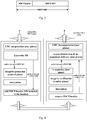
Fig. 4 is a schematic view showing a location of a UDC in a PDCP data processing flow; -
Fig. 5 is a schematic view of a PDCP PDU format; -
Fig. 6 is another schematic view of a PDCP PDU format; -
Fig. 7 is still another schematic view of a PDCP PDU format. -
Fig. 8 is a flowchart of a method for decompressing uplink data according to an embodiment of the present disclosure; -
Fig. 9 is a flowchart of a method for compressing uplink data according to an embodiment of the present disclosure; -
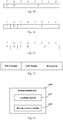
Fig. 10 is a schematic view of a format of a UDC header with three fields in an embodiment of the present disclosure; -
Fig. 11 is a schematic view of a format of a UDC header with four fields in an embodiment of the present disclosure; -
Fig. 12 is a schematic view of a format of a UDC header with five fields in an embodiment of the present disclosure; -
Fig. 13 is a schematic view of a PDCP PDU format with a UDC header in an embodiment of the present disclosure; -
Fig. 14 is a schematic structural view of a decompression end in an embodiment of the present disclosure; -
Fig. 15 is a schematic structural view of a compression end in an embodiment of the present disclosure. -
Fig. 16 is a schematic structural view of a decompression end in another embodiment of the present disclosure; and -
Fig. 17 is a schematic structural view of a compression end in another embodiment of the present disclosure. - Exemplary embodiments of the present disclosure will be described in more detail with reference to the accompanying drawings hereinafter. While the exemplary embodiments of the present disclosure are shown in the drawings, it should be understood that the present disclosure may be carried out in various forms without being limited by the embodiments set forth herein. Rather, these embodiments are provided so that the present disclosure can be understood more thoroughly and the scope of the present disclosure can be fully conveyed to a person skilled in the art.
- In embodiments of the present disclosure, the UDC compression algorithm as used is a compression algorithm of the published Request for Comments (RFC) 1951. For details, please refer to the RFC 1951 document of the Internet Engineering Task Force (IETF).
- Referring to
Figs.5, 6, and 7 , format of a PDCP packet after the UDC compression is shown. A UDC block in the figures is a data packet compressed with RFC1951, and the compression object is a PDCP SDU (Service Data Unit), i.e., a data packet sent transmitted from an upper layer. - Referring to
Fig. 8 , a method for decompressing uplink data is shown, which includes the following steps. - Step 801: checking, by a decompression end, a UDC header in a PDCP packet after the PDCP packet is received by the decompression end, where the UDC header includes at least: compression context information of a data packet in the PDCP packet and information related to a decompression buffer area, and the information related to the decompression buffer area is for indicating the decompression end to control the decompression buffer area of the decompression end to keep consistent with a compression buffer area of a compression end.
- The above compression context information may be an indication bit field for indicating whether UDC compression is performed. The above information related to the decompression buffer area may include an indication bit field indicating compression buffer area resetting and an indication bit field for decompression buffer area checking. By using the information related to the decompression buffer area, consistency between the compression buffer area of the compression end and the decompression buffer area of the decompression end can be effectively ensured, thereby improving reliability of uplink data compression.
- In the embodiment, the decompression end refers to an entity where the network side PDCP is located. For example, the decompression end refers to the PDCP layer of a base station, and the PDCP layer is located in a base station or a centralized unit (CU) of a distributed base station.
- Step 802: performing, by the decompression end, a corresponding operation on the data packet in the PDCP packet according to the compression context information and the information related to the decompression buffer area.
- In the embodiment, optionally, the PDCP packet includes: a header of the PDCP packet, the UDC header, and the data packet, and the UDC header is between the header of the PDCP packet and the data packet.
- In the embodiment, optionally, the UDC header includes one or more of the followings:
- a first indication bit field for indicating whether UDC compression is performed;
- a second indication bit field for indicating decompression buffer area resetting; or
- a third indication bit field for indicating decompression buffer area checking.
- In the embodiment, optionally, the UDC header further includes a fourth indication bit field for indicating whether the data packet is to enter the decompression buffer area; or a reserved bit field.
- Specifically, in conjunction with the structure of the above UDC header, the decompression end may perform the corresponding operation on the data packet in the PDCP packet in the following way in the embodiment:
- in a case that the first indication bit field in the UDC header has a first value indicating that UDC compression is not performed, the decompression end directly transmits the data packet to an upper layer;
- in a case that the first indication bit field has a second value indicating that UDC compression is performed, the decompression end checks the second indication bit field in the UDC header for indicating the decompression buffer area resetting;
- in a case that the second indication bit field has a third value indicating that the decompression buffer area resetting needs to be performed, the decompression buffer area is cleared, the third indication bit field for indicating the decompression buffer area checking is not required to be checked, and UDC decompression is performed on the data packet directly;
- in a case that the second indication bit field has a fourth value indicating that the decompression buffer area resetting is not required, the third indication bit field for indicating the decompression buffer area checking is continued to be checked; and
- in a case that the third indication bit field is n bits, the decompression end checks data in the decompression buffer area, and takes n bits from the decompression buffer area, and in a case that the taken n bits are the same as the third indication bit field in the UDC header, UDC decompression is performed on the data packet, and the decompressed data pack enters the decompression buffer area; otherwise, a reset process is initiated, and the compression end is instructed to perform a reset of the compression buffer area, where n is a positive integer.
- The above way of taking n bits from the compression buffer area may be: superimposing according to the entire byte or superimposing all bits in the decompression buffer area, and taking the last n bits.
- Optionally, in the embodiment, in a case that the UDC header includes the second indication bit field for indicating whether the data packet is to enter the decompression buffer area, and the second indication bit field has a fifth value indicating that the data packet needs to enter the decompression buffer area, the data packet is stored in the decompression buffer area, where the data packet is an uncompressed data packet or a decompressed data packet;
in a case that the UDC header includes the second indication bit field for indicating whether the data packet is to enter the decompression buffer area, and the second indication bit field has a sixth value indicating that the data packet does not need to enter the decompression buffer area, the data packet is not stored in the decompression buffer area. - In the embodiment, the UDC header is added in the PDCP packet, the UDC header includes at least the compression context information of the data packet in the PDCP packet and the information related to the decompression buffer area, and the decompression end is capable of performing the corresponding operation on the data packet in the PDCP packet according to the compression context information and the information related to the decompression buffer area. In this way, the decompression end controls the decompression buffer area to keep consistent with the compression buffer area of the compression end according to the information related to the decompression buffer area. As such, the problem that consistency between the compression buffer and the decompression buffer on the two sides of base station and UE cannot be ensured in the related technologies is solved, thereby improving reliability of uplink data compression.
- Referring to
Fig. 9 , a method for compressing uplink data is shown, which includes the following step. - Step 901: transmitting, by a compression end, a PDCP packet to a decompression end such that the decompression end checks a UDC header in the PDCP packet, where the UDC header includes at least: compression context information of a data packet in the PDCP packet and information related to a decompression buffer area; a corresponding operation is performed by the decompression end on the data packet in the PDCP packet according to the compression context information and the information related to the decompression buffer area, and the information related to the decompression buffer area is for indicating the decompression end to control the decompression buffer area of the decompression end to keep consistent with a compression buffer area of the compression end.
- In the embodiment, the above compression end refers to an entity where the User Equipment (UE) side PDCP is located, and the entity has a function of performing UDC compression on uplink data; for example, the compression end may correspond to the UE.
- In the embodiment, optionally, the PDCP packet includes: a header of the PDCP packet, the UDC header, and the data packet, and the UDC header is between the header of the PDCP packet and the data packet.
- In the embodiment, optionally, the UDC header includes one or more of the followings:
- a first indication bit field for indicating whether UDC compression is performed;
- a second indication bit field for indicating decompression buffer area resetting; or
- a third indication bit field for indicating decompression buffer area checking.
- In the embodiment, optionally, the method further includes:
- in a case that UDC compression is performed on the data packet in the PDCP packet, setting, by the compression end, the first indication bit field for indicating whether UDC compression is performed as a second value; otherwise, setting, by the compression end, the first indication bit field as a first value; and
- in a case the first indication bit field is set as the second value, superimposing, by the compression end, data in the compression buffer area before the compression, calculating the third indication bit field for indicating decompression buffer area checking, and putting it in the UDC header.
- In the embodiment, optionally, the UDC header further includes a fourth indication bit field for indicating whether the data packet is to enter the decompression buffer area; or a reserved bit field.
- In the embodiment, optionally, the method further includes:
- in a case that the data packet needs to enter the compression buffer area, setting, by the compression end, the fourth indication bit field in the UDC header for indicating whether the data packet is to enter the decompression buffer area as a fifth value; and
- in a case that the data packet does not need to enter the compression buffer area, setting, by the compression end, the fourth indication bit field in the UDC header for indicating whether the data packet is to enter the decompression buffer area as a sixth value.
- In the embodiment, the decompression end is capable of controlling the decompression buffer area to keep consistent with the compression buffer area of the compression end according to the information related to the decompression buffer area in the UDC header. As such, the problem that consistency between the compression buffer and the decompression buffer on the two sides of base station and UE cannot be ensured in the related technologies is solved, thereby improving reliability of uplink data compression.
- In another embodiment of the present disclosure, a UDC header is added between the header of the PDCP and the data packet (which may also be referred to as a UDC compressed packet), and the UDC header may cover one or more of the following fields:
- an indication bit field for indicating whether UDC compression is performed;
- an indication bit field for indicating buffer area resetting; and
- an indication bit field for indicating buffer area checking.
- Optionally, the UDC header further includes an indication bit field for indicating whether the packet is to enter the buffer area.
- Optionally, the UDC header further includes a reserved bit field.
- In the embodiment, after the decompression end receives the data packet, it checks the UDC header, and performs a decompression operation of UDC. The decompression end may be a base station.
- The specific behavior of the decompression end is described as follows:
- in
step 1, the decompression end checks the indication bit field for indicating whether UDC compression is performed; if the UDC compression is not performed, the UDC decompression step is skipped, and the PDCP SDU is directly delivered to the upper layer; and if the UDC compression is performed, the process proceeds to step 2; - in
step 2, the indication bit field for indicating buffer area resetting is checked; if it is set to 1, the decompress buffer area is cleared, the indication bit field for indicating buffer area checking is not required to be checked, and the decompression module of UDC proceeds to decompress; and if it is set to 0, checking of the indication bit field for indicating the buffer area checking is continued. - Assuming that the indication bit field for indicating the buffer area checking is n bits (n may be 1-7, for example, 4), the decompression end checks the data in the decompression buffer area. For example, it superimposes according to the entire byte or superimposes all the bits in the buffer area, and takes the last n bits. If the taken n bits are the same as the indication bit field in the received UDC header for indicating decompression buffer area checking, they are considered to be consistent, and UDC decompression may be performed; and if they are inconsistent, a reset process is initiated, and the compression end is instructed to perform a reset of the compression buffer area.
- Optionally, the behavior of the decompression end may further include step 3: if the header of the UDC carries an indication bit field for indicating whether the data packet is to enter the buffer area and the indication bit field is 1, then regardless of whether the data packet is a UDC compressed packet, the data in the data packet (uncompressed data packet or decompressed data) is compressed into the decompression buffer area for saving; and if the indication bit field is 0, the data in the data packet is not compressed into the decompression buffer area.
- The specific behavior of the compression end is described as follows:
- Step 1: whether to perform compression may be determined according to the configuration on the network side. For example, if the compression ratio exceeds a certain threshold (for example, 10% or more is compressed), it is determined that the compressed packet is transmitted, and the indication bit field for indicating whether UDC compression is performed is set to 1; otherwise, the indication bit field for indicating whether UDC compression is performed is set to 0.
- Step 2: if the indication bit field for indicating whether UDC compression is performed is set to 1, summing operation is performed on the compression buffer area before compression, and the indication bit field for indicating decompression buffer area checking is calculated and put in the header of the UDC.
- Step 3: if the packet of data is to enter the compression buffer area, the indication bit field in the UDC header for indicating whether the data packet is to enter the buffer area is set to 1, otherwise, the indication bit field for indicating whether the data packet is to enter the buffer area is set to 0.
- Embodiment 1: there are three fields in the UDC header
Referring toFig. 10 , format of a UDC header includes the following information: - an indication bit field for indicating whether UDC compression is performed (U: 1 bit);
- an indication bit field for indicating whether to reset the decompression buffer area (N: 1 bit); and
- an indication bit field for indicating decompression buffer area checking (C information: 6 bits).
- The PDCP layer of the UE performs UDC compression on the data transmitted from the upper layer. If it is determined to transmit the compressed data packet to the network, U is set to 1, the data in the compression buffer area before compression is superimposed, and the last 6 bits of information are put in the C field of UDC.
- If it is determined not to compress the packet of data, U is set to 0. A default value or an arbitrary value may be put in the C field, or the last 6 bits of the compression buffer area after superimposition may be put in the C field.
- If it is required for the UE to reset the compression buffer area according to configuration of the network side or when the compression buffer area is found to have a problem, the N field is set to 1; otherwise, it is set to 0.
- After the base station receives the packet of data, if U is 0, the header portion of the UDC is skipped, decompression is not performed, and the subsequent data packet is directly delivered to the upper layer. If the N field is 1, the data in the decompression buffer area is cleared. If U is 1 and the N field is 0, the data in the decompression buffer area is checked and superimposed, and the last 6 bits are taken. If the last 6 bits are the same as the check bit field of the C field in the header of the UDC as received, they are considered to be consistent, and the UDC decompression module may be entered for decompression. At the same time, the decompressed data packet enters the decompression buffer area.
- It should be noted that, the data superposition of the compression buffer area may be implemented in various ways, such as superimposing according to entire byte and taking the last n bits, or superposing according to bit and taking the last n bits. The specific way may be agreed by protocol.
- Embodiment 2: there are four fields in the UDC header
Referring toFig. 11 , format of a UDC header includes the following information: - an indication bit field for indicating whether UDC compression is performed (U: 1 bit);
- an indication bit field for indicating whether to reset the decompression buffer area (N: 1 bit);
- an indication bit field for indicating whether to enter the decompression buffer area (I: 1 bit); and
- an indication bit field for indicating decompression buffer area checking (C information: 6 bits).
- Similar to the above described
Embodiment 1, the usages of the U field, the N field, and the C field inEmbodiment 2 are the same as those inEmbodiment 1. How to use the above I field is described below. The I field indicates whether the packet of data is going to enter the decompression buffer area. Regardless of whether the data packet is compressed, once I is set to 1, the base station compresses the uncompressed data packet (in a case that U is 0) or the decompressed data packet (in a case that U is 1) into the decompression buffer area. - Embodiment 3: there are five fields in the UDC header
Referring toFig. 12 , format of a UDC header includes the following information: - an indication bit field configured to indicate whether UDC compression is preformed (U: 1 bit);
- an indication bit field for indicating whether to reset the buffer area (N: 1 bit);
- an indication bit field for indicating whether to enter the buffer area (I: 1 bit);
- an indication bit field for indicating buffer area checking (C information: 4 bits); and
- a reserved bit field (R: 2 bits).
- The usages of the U field, the I field, and the C field in
Embodiment 3 are the same as those inEmbodiment 1 andEmbodiment 2, except for the fact that the C field of 4 bits is used inEmbodiment 3. There are two bits of R field whose function is not defined temporarily, and are left for future use. - Embodiment 4: location of UDC header
Referring toFig. 13 , when a Data Resource Bearer (DRB) is configured to use the UDC, a 1-byte UDC header is inserted between the original PDCP header and the data portion. The UDC header always exists during UDC activation. - Embodiment 5: a case of inconsistency in the check field C field of the buffer area
In a case that the decompression end finds that the indication bit field for indicating the decompression buffer area checking is inconsistent with the information in the received data packet, all the information of the decompression buffer area is cleared, and the indication bit field for indicating the decompression buffer area checking is set to 0, and is notified to the compression end (i.e., the UE) through signaling. - Optionally, the signaling may be RRC signaling, such as indicating clearing the UDC compression buffer area of a certain DRB in a reconfiguration message.
- Optionally, the signaling may also be a control PDU of a new PDCP or a 1-bit indication information carried in the control PDU of the existing PDCP. For example, the R bit field in the control PDU is redefined to indicate resetting the buffer area.
- When the compression end receives the reset indication information, the compression buffer area is cleared, and the reset indication bit field in the PDU in the previous embodiments indicates that the decompression end has performed reset to ensure that the statuses of the buffer areas on both sides are consistent.
- Based on the same inventive concept, a decompression end is further provided in an embodiment of the present disclosure. The principle of solving the problem by the decompression end is similar to that of the method for decompressing the uplink data shown in
Fig. 8 in the embodiment of the present disclosure. Therefore, for the implementation of the decompression end, reference may be made to the implementation of the method, and repeated description is omitted herein. - Referring to
Fig. 14 , a structure of a decompression end is shown, and the decompression end 1400 includes: - a
checking module 1401, configured to check a UDC header in a PDCP packet after the PDCP packet is received by the checking module, where the UDC header includes at least: compression context information of a data packet in the PDCP packet and information related to a decompression buffer area, and the information related to the decompression buffer area is for indicating the decompression end to control the decompression buffer area of the decompression end to keep consistent with a compression buffer area of a compression end; and - a
first processing module 1402, configured to perform a corresponding operation on the data packet in the PDCP packet according to the compression context information and the information related to the decompression buffer area. - In the embodiment, optionally, the PDCP packet includes: a header of the PDCP packet, the UDC header, and the data packet, and the UDC header is between the header of the PDCP packet and the data packet.
- In the embodiment, optionally, the UDC header includes one or more of the followings:
- a first indication bit field for indicating whether UDC compression is performed;
- a second indication bit field for indicating decompression buffer area resetting; or
- a third indication bit field for indicating decompression buffer area checking.
- In the embodiment, optionally, the UDC header further includes:
a fourth indication bit field for indicating whether the data packet is to enter the decompression buffer area; or a reserved bit field. - In the embodiment, optionally, the processing module is further configured to:
- in a case that the first indication bit field in the UDC header has a first value indicating that UDC compression is not performed, enable the decompression end to directly transmit the data packet to an upper layer;
- in a case that the first indication bit field has a second value indicating that UDC compression is performed, enable the decompression end to check the second indication bit field in the UDC header for indicating the decompression buffer area resetting;
- in a case that the second indication bit field has a third value indicating that the decompression buffer area resetting needs to be performed, clear the decompression buffer area, where the third indication bit field for indicating the decompression buffer area checking is not required to be checked, and UDC decompression is performed on the data packet directly;
- in a case that the second indication bit field has a fourth value indicating that the decompression buffer area resetting is not required, continue to check the third indication bit field for indicating the decompression buffer area checking; and
- in a case that the third indication bit field is n bits, enable the decompression end to check data in the decompression buffer area, and take n bits from the decompression buffer area, and in a case that the taken n bits are the same as the third indication bit field in the UDC header, perform UDC decompression on the data packet; otherwise, initiate a reset process and instruct the compression end to perform a reset of the compression buffer area, where n is a positive integer.
- In the embodiment, optionally, the decompression end further includes:
- a second processing module configured to, in a case that the UDC header includes the second indication bit field for indicating whether the data packet is to enter the decompression buffer area, and the second indication bit field has a fifth value indicating that the data packet needs to enter the decompression buffer area, store the data packet in the decompression buffer area, where the data packet is an uncompressed data packet or a decompressed data packet;
- in a case that the UDC header includes the second indication bit field for indicating whether the data packet is to enter the decompression buffer area, and the second indication bit field has a sixth value indicating that the data packet does not need to enter the decompression buffer area, the data packet is not stored in the decompression buffer area.
- Based on the same inventive concept, a compression end is further provided in an embodiment of the present disclosure. The principle of solving the problem by the compression end is similar to that of the method for compressing the uplink data shown in
Fig. 9 in the embodiment of the present disclosure. Therefore, for the implementation of the compression end, reference may be made to the implementation of the method, and repeated description is omitted herein. - Referring to
Fig. 15 , a structure of a compression end is shown, and thecompression end 1500 includes:
atransmitting module 1501, configured to transmit a PDCP packet to a decompression end such that the decompression end checks a UDC header in the PDCP packet, where the UDC header includes at least: compression context information of a data packet in the PDCP packet and information related to a decompression buffer area; a corresponding operation is performed by the decompression end on the data packet in the PDCP packet according to the compression context information and the information related to the decompression buffer area, and the information related to the decompression buffer area is for indicating the decompression end to control the decompression buffer area of the decompression end to keep consistent with a compression buffer area of the compression end. - In the embodiment, optionally, the PDCP packet includes: a header of the PDCP packet, the UDC header, and the data packet, and the UDC header is between the header of the PDCP packet and the data packet.
- In the embodiment, optionally, the UDC header includes one or more of the followings:
- a first indication bit field for indicating whether UDC compression is performed;
- a second indication bit field for indicating decompression buffer area resetting; or
- a third indication bit field for indicating decompression buffer area checking.
- In the embodiment, optionally, the compression end further includes:
a first setting module configured to, in a case that UDC compression is performed on the data packet in the PDCP packet, set the first indication bit field for indicating whether UDC compression is performed as a second value, otherwise, enable the compression end to set the first indication bit field as a first value; or in a case the first indication bit field is set as the second value, superimpose data in the compression buffer area before the compression, calculate the third indication bit field for indicating decompression buffer area checking, and put it in the UDC header. - In the embodiment, optionally, the UDC header further includes:
a fourth indication bit field for indicating whether the data packet is to enter the decompression buffer area; or a reserved bit field. - In the embodiment, optionally, the compression end further includes:
- a second setting module configured to, in a case that the data packet needs to enter the compression buffer area, set the fourth indication bit field in the UDC header for indicating whether the data packet is to enter the decompression buffer area as a fifth value; and
- in a case that the data packet does not need to enter the compression buffer area, set the fourth indication bit field in the UDC header for indicating whether the data packet is to enter the decompression buffer area as a sixth value.
- An embodiment of the present disclosure further provides a decompression end, which includes: a first memory, a first processor, and a computer program which is stored in the first memory and is capable of being executed by the first processor, when the program is executed by the first processor, steps in the above described method for decompressing uplink data are implemented.
- Referring to
Fig. 16 , a structure of a decompression end is shown, which includes: afirst memory 1604, afirst processor 1601, and a computer program which is stored in thefirst memory 1604 and is capable of being executed by thefirst processor 1601, when the program is executed by thefirst processor 1601, the following steps are implemented: checking a UDC header in a PDCP packet after the PDCP packet is received, where the UDC header includes at least: compression context information of a data packet in the PDCP packet and information related to a decompression buffer area, and the information related to the decompression buffer area is for indicating the decompression end to control the decompression buffer area of the decompression end to keep consistent with a compression buffer area of a compression end; and performing a corresponding operation on the data packet in the PDCP packet according to the compression context information and the information related to the decompression buffer area. - In
Fig. 16 , a bus architecture (represented by a first bus 1600) may include any quantity of interconnected buses and bridges. Various circuits including one or more processors represented by thefirst processor 1601 and a memory represented by thefirst memory 1604 are coupled via thefirst bus 1600. Thefirst bus 1600 may further couple various other circuits together, such as a periphery component, a voltage stabilizer and a power management circuit. Afirst bus interface 1603 provides an interface between thefirst bus 1600 and afirst transceiver 1602. Thefirst transceiver 1602 may be one element, or multiple elements, such as multiple receivers and transmitters, providing a unit for communicating with various other devices on a transmission medium. For example, thefirst transceiver 1602 receives external data from other devices. Thefirst transceiver 1602 is configured to transmit data processed by thefirst processor 1601 to other devices. - The
first processor 1601 is in charge of managing thefirst bus 1600 and common processes, such as running a general operating system. Thefirst memory 1604 may be configured to store data used by thefirst processor 1601 in performing operations. - Optionally, the
first processor 1601 may be a CPU, an application specific integrated circuit (ASIC), a field-programmable gate array (FPGA), or a complex programmable logic device (CPLD). - An embodiment of the present disclosure further provides a compression end, which includes: a second memory, a second processor, and a computer program which is stored in the second memory and is capable of being executed by the second processor, when the program is executed by the second processor, steps in the above described method for compressing uplink data are implemented.
- Referring to
Fig. 17 , a structure of a compression end is shown, which includes: a second memory, a second processor , and a computer program which is stored in the second memory and is capable of being executed by the second processor, when the program is executed by the second processor, the following steps are implemented: transmitting a PDCP packet to a decompression end such that the decompression end checks a UDC header in the PDCP packet, where the UDC header includes at least: compression context information of a data packet in the PDCP packet and information related to a decompression buffer area; a corresponding operation is performed by the decompression end on the data packet in the PDCP packet according to the compression context information and the information related to the decompression buffer area, and the information related to the decompression buffer area is for indicating the decompression end to control the decompression buffer area of the decompression end to keep consistent with a compression buffer area of the compression end. - In
Fig. 17 , a bus architecture (represented by a second bus 1700) may include any quantity of interconnected buses and bridges. Various circuits including one or more processors represented by thesecond processor 1701 and a memory represented by thesecond memory 1704 are coupled via thesecond bus 1700. Thesecond bus 1700 may further couple various other circuits together, such as a periphery component, a voltage stabilizer and a power management circuit. Asecond bus interface 1703 provides an interface between thesecond bus 1700 and asecond transceiver 1702. Thesecond transceiver 1702 may be one element, or multiple elements, such as multiple receivers and transmitters, providing a unit for communicating with various other devices on a transmission medium. For example, thesecond transceiver 1702 receives external data from other devices. Thesecond transceiver 1702 is configured to transmit data processed by thesecond processor 1701 to other devices. Depending on the nature of the computing system, a user interface 1105 may also be provided, such as a keypad, a display, a speaker, microphone, and a joystick. - The
second processor 1701 is in charge of managing thesecond bus 1700 and common processes, such as running a general operating system. Thesecond memory 1704 may be configured to store data used by thesecond processor 1701 in performing operations. - Optionally, the
second processor 1701 may be a CPU, an application specific integrated circuit (ASIC), a field-programmable gate array (FPGA), or a complex programmable logic device (CPLD). - An embodiment of the present disclosure further provides a computer readable storage medium, on which a computer program is stored, when the program is executed by a processor, steps in the above described method for decompressing uplink data are implemented, or steps in the above described method for compressing uplink data are implemented.
- It should be understood that "one embodiment" or "an embodiment" mentioned throughout the specification means that specific features, structures or characteristics associated with the embodiment are included in at least one embodiment of the present disclosure. Hence, terms of "according to one embodiment" or "according to an embodiment" in the specification are not limited to the same embodiment. In addition, those specific features, structures or characteristics can be combined in one or more embodiments in any appropriate manner
It should be understood, numerical references for respective processes in the embodiments of the present disclosure do not indicate any execution sequence, and these numerical references are not to limit implementation processes of the embodiments of the present disclosure. Execution sequences of the processes are determined based on functions and internal logics of the processes. - In addition, terms of "system" and "network" in the specification may be interchanged.
- It should be understood that, the term "and/or" merely describes a relationship between associated objects. Such term may indicate three situations. For example, A and/or B may indicate: mere A, both A and B, or mere B. Furthermore, the symbol "/" usually indicates an "or" relationship between associated objects prior to and after such symbol.
- It should be understood that in the embodiments of the present disclosure, "B corresponding to A" indicates that B is associated with A and may be determined based on A. However, it should also be understood that determining B based on A does not mean determining B based on only A, and B may be determined based on A and/or other information.
- It should be understood that the method and device provided in the embodiments of the present disclosure may be implemented in other ways. For example, the described embodiments directed to the device are merely exemplary. For example, the units are divided merely in logical function, which may be divided in another way in actual implementation, e.g., multiple units or components may be combined or integrated into another system, or some features may be ignored or not performed. In addition, the disclosed or discussed mutual coupling or direct coupling or communication connection may be an indirect coupling or communication connection through some interfaces, devices or units, which may be implemented in electronic, mechanical or other forms.
- Furthermore, functional units in the embodiments of the present disclosure may be integrated into one processing unit, or may be physically independent, or two or more units are integrated into one unit. The integrated units may be implemented by hardware or by combination of hardware and software functional units.
- Integrated units implemented as software functional units may be stored on a computer readable storage medium. The software functional units are stored on a storage medium and include several instructions for enabling a computer device (which may be a personal computer, a server, a network apparatus or the like) to execute partial steps of methods according to embodiments of the present disclosure. The storage medium may include medium that can store program code, such as a USB flash disk, a mobile Hard Disk, a Read-Only Memory (ROM), a Random Access Memory (RAM), a magnetic disk or an optical disk.
- Optional embodiments are described hereinabove. It should be noted that various improvements and polishments can be made by those ordinary skilled in the art without departing from the principle of the present disclosure. The improvements and polishments fall within the protection scope of the present disclosure.
Claims (28)
- A method for decompressing uplink data, comprising:checking, by a decompression end, an uplink data compression (UDC) header in a packet data convergence protocol (PDCP) packet after the PDCP packet is received by the decompression end, wherein the UDC header comprises at least: compression context information of a data packet in the PDCP packet and information related to a decompression buffer area, and the information related to the decompression buffer area is for indicating the decompression end to control the decompression buffer area of the decompression end to keep consistent with a compression buffer area of a compression end; andperforming, by the decompression end, a corresponding operation on the data packet in the PDCP packet according to the compression context information and the information related to the decompression buffer area.
- The method according to claim 1, wherein the PDCP packet comprises: a header of the PDCP packet, the UDC header, and the data packet, and the UDC header is between the header of the PDCP packet and the data packet.
- The method according to claim 1, wherein the UDC header comprises one or more of:a first indication bit field for indicating whether UDC compression is performed;a second indication bit field for indicating decompression buffer area resetting; ora third indication bit field for indicating decompression buffer area checking.
- The method according to claim 3, wherein the UDC header further comprises:
a fourth indication bit field for indicating whether the data packet is to enter the decompression buffer area; or a reserved bit field. - The method according to claim 3, wherein the performing, by the decompression end, the corresponding operation on the data packet in the PDCP packet according to the compression context information and the information related to the decompression buffer area comprises:transmitting, by the decompression end directly, the data packet to an upper layer, in a case that the first indication bit field in the UDC header has a first value indicating that UDC compression is not performed;checking, by the decompression end, the second indication bit field in the UDC header for indicating the decompression buffer area resetting, in a case that the first indication bit field has a second value indicating that UDC compression is performed;clearing the decompression buffer area, in a case that the second indication bit field has a third value indicating that the decompression buffer area resetting needs to be performed, wherein the third indication bit field for indicating the decompression buffer area checking does not need to be checked, and UDC decompression is performed on the data packet directly;continuing to check the third indication bit field for indicating the decompression buffer area checking, in a case that the second indication bit field has a fourth value indicating that the decompression buffer area resetting does not need to be performed; andchecking, by the decompression end, data in the decompression buffer area, and taking n bits from the decompression buffer area, in a case that the third indication bit field is n bits, and performing UDC decompression on the data packet in a case that the taken n bits are the same as the third indication bit field in the UDC header; otherwise, initiating a reset process and instructing the compression end to perform a reset of the compression buffer area, where n is a positive integer.
- The method according to claim 5, wherein taking n bits from the compression buffer area comprises:
superimposing based on entire byte or superimposing all bits in the decompression buffer area, and taking the last n bits. - The method according to claim 4, further comprising:storing the data packet in the decompression buffer area, in a case that the UDC header comprises the second indication bit field for indicating whether the data packet is to enter the decompression buffer area, and the second indication bit field has a fifth value indicating that the data packet needs to enter the decompression buffer area, wherein the data packet is an uncompressed data packet or a decompressed data packet;wherein in a case that the UDC header comprises the second indication bit field for indicating whether the data packet is to enter the decompression buffer area, and the second indication bit field has a sixth value indicating that the data packet does not need to enter the decompression buffer area, the data packet is not stored in the decompression buffer area.
- A method for compressing uplink data, comprising:transmitting, by a compression end, a PDCP packet to a decompression end such that the decompression end checks a UDC header in the PDCP packet, wherein the UDC header comprises at least: compression context information of a data packet in the PDCP packet and information related to a decompression buffer area;a corresponding operation is performed by the decompression end on the data packet in the PDCP packet according to the compression context information and the information related to the decompression buffer area, and the information related to the decompression buffer area is for indicating the decompression end to control the decompression buffer area of the decompression end to keep consistent with a compression buffer area of the compression end.
- The method according to claim 8, wherein the PDCP packet comprises: a header of the PDCP packet, the UDC header, and the data packet, and the UDC header is between the header of the PDCP packet and the data packet.
- The method according to claim 8, wherein the UDC header comprises one or more of:a first indication bit field for indicating whether UDC compression is performed;a second indication bit field for indicating decompression buffer area resetting; ora third indication bit field for indicating decompression buffer area checking.
- The method according to claim 10, further comprising:setting, by the compression end, the first indication bit field for indicating whether UDC compression is performed as a second value, in a case that UDC compression is performed on the data packet in the PDCP packet, otherwise, setting, by the compression end, the first indication bit field as a first value; andsuperimposing, by the compression end, data in the compression buffer area before the compression, in a case the first indication bit field is set as the second value, calculating the third indication bit field for indicating the decompression buffer area checking, and putting it in the UDC header.
- The method according to claim 10, wherein the UDC header further comprises:
a fourth indication bit field for indicating whether the data packet is to enter the decompression buffer area; or a reserved bit field. - The method according to claim 12, further comprising:setting, by the compression end, the fourth indication bit field in the UDC header for indicating whether the data packet is to enter the decompression buffer area as a fifth value, in a case that the data packet needs to enter the compression buffer area; andsetting, by the compression end, the fourth indication bit field in the UDC header for indicating whether the data packet is to enter the decompression buffer area as a sixth value, in a case that the data packet does not need to enter the compression buffer area.
- A decompression end, comprising:a checking module, configured to check a UDC header in a PDCP packet after the PDCP packet is received by the checking module, wherein the UDC header comprises at least: compression context information of a data packet in the PDCP packet and information related to a decompression buffer area, and the information related to the decompression buffer area is for indicating the decompression end to control the decompression buffer area of the decompression end to keep consistent with a compression buffer area of a compression end; anda first processing module, configured to perform a corresponding operation on the data packet in the PDCP packet according to the compression context information and the information related to the decompression buffer area.
- The decompression end according to claim 14, wherein the PDCP packet comprises: a header of the PDCP packet, the UDC header, and the data packet, and the UDC header is between the header of the PDCP packet and the data packet.
- The decompression end according to claim 14, wherein the UDC header comprises one or more of:a first indication bit field for indicating whether UDC compression is performed;a second indication bit field for indicating decompression buffer area resetting; ora third indication bit field for indicating decompression buffer area checking.
- The decompression end according to claim 16, wherein the UDC header further comprises:
a fourth indication bit field for indicating whether the data packet is to enter the decompression buffer area; or a reserved bit field. - The decompression end according to claim 16, wherein the first processing module is further configured to:in a case that the first indication bit field in the UDC header has a first value indicating that UDC compression is not performed, enable the decompression end to directly transmit the data packet to an upper layer;in a case that the first indication bit field has a second value indicating that UDC compression is performed, enable the decompression end to check the second indication bit field in the UDC header for indicating the decompression buffer area resetting;in a case that the second indication bit field has a third value indicating that the decompression buffer area resetting needs to be performed, clear the decompression buffer area, wherein the third indication bit field for indicating the decompression buffer area checking does not need to be checked, and UDC decompression is performed on the data packet directly;in a case that the second indication bit field has a fourth value indicating that the decompression buffer area resetting does not need to be performed, continue to check the third indication bit field for indicating the decompression buffer area checking; andin a case that the third indication bit field is n bits, enable the decompression end to check data in the decompression buffer area, and take n bits from the decompression buffer area, and in a case that the taken n bits are the same as the third indication bit field in the UDC header, perform UDC decompression on the data packet; otherwise, initiate a reset process and instruct the compression end to perform a reset of the compression buffer area, where n is a positive integer.
- The decompression end according to claim 17, further comprising:a second processing module configured to, in a case that the UDC header comprises the second indication bit field for indicating whether the data packet is to enter the decompression buffer area, and the second indication bit field has a fifth value indicating that the data packet needs to enter the decompression buffer area, store the data packet in the decompression buffer area, wherein the data packet is an uncompressed data packet or a decompressed data packet;wherein in a case that the UDC header comprises the second indication bit field for indicating whether the data packet is to enter the decompression buffer area, and the second indication bit field has a sixth value indicating that the data packet does not need to enter the decompression buffer area, the data packet is not stored in the decompression buffer area.
- A compression end, comprising:
a transmitting module, configured to transmit a PDCP packet to a decompression end such that the decompression end checks a UDC header in the PDCP packet, wherein the UDC header comprises at least: compression context information of a data packet in the PDCP packet and information related to a decompression buffer area; a corresponding operation is performed by the decompression end on the data packet in the PDCP packet according to the compression context information and the information related to the decompression buffer area, and the information related to the decompression buffer area is for indicating the decompression end to control the decompression buffer area of the decompression end to keep consistent with a compression buffer area of the compression end. - The compression end according to claim 20, wherein the PDCP packet comprises: a header of the PDCP packet, the UDC header, and the data packet, and the UDC header is between the header of the PDCP packet and the data packet.
- The compression end according to claim 20, wherein the UDC header comprises one or more of:a first indication bit field for indicating whether UDC compression is performed;a second indication bit field for indicating decompression buffer area resetting; ora third indication bit field for indicating decompression buffer area checking.
- The compression end according to claim 22, further comprising:
a first setting module configured to, in a case that UDC compression is performed on the data packet in the PDCP packet, set the first indication bit field for indicating whether UDC compression is performed as a second value, otherwise, enable the compression end to set the first indication bit field as a first value; or in a case the first indication bit field is set as the second value, superimpose data in the compression buffer area before the compression, calculate the third indication bit field for indicating decompression buffer area checking, and put it in the UDC header. - The compression end according to claim 22, wherein the UDC header further comprises:
a fourth indication bit field for indicating whether the data packet is to enter the decompression buffer area; or a reserved bit field. - The compression end according to claim 24, wherein the compression end further comprises:a second setting module configured to, in a case that the data packet needs to enter the compression buffer area, set the fourth indication bit field in the UDC header for indicating whether the data packet is to enter the decompression buffer area as a fifth value; andin a case that the data packet does not need to enter the compression buffer area, set the fourth indication bit field in the UDC header for indicating whether the data packet is to enter the decompression buffer area as a sixth value.
- A decompression end, comprising a first memory, a first processor, and a computer program stored in the first memory and executable by the first processor, wherein when the computer program is executed by the first processor, steps in the method for decompressing uplink data according to any one of claims 1 to 7 are implemented.
- A compression end, comprising a second memory, a second processor, and a computer program stored in the second memory and executable by the second processor, wherein when the computer program is executed by second processor, steps in the method for compressing uplink data according to any one of claims 8 to 13 are implemented.
- A computer readable storage medium, on which a computer program is stored, wherein when the computer program is executed by a processor, steps in the method for decompressing uplink data according to any one of claims 1 to 7 are implemented, or steps in the method for compressing uplink data according to any one of claims 8 to 13 are implemented.
Applications Claiming Priority (2)
| Application Number | Priority Date | Filing Date | Title |
|---|---|---|---|
| CN201710296106.4A CN107094142B (en) | 2017-04-28 | 2017-04-28 | Method and device for decompressing and compressing uplink data |
| PCT/CN2018/078451 WO2018196491A1 (en) | 2017-04-28 | 2018-03-08 | Method and apparatus for decompressing and compressing uplink data |
Publications (3)
| Publication Number | Publication Date |
|---|---|
| EP3618392A1 true EP3618392A1 (en) | 2020-03-04 |
| EP3618392A4 EP3618392A4 (en) | 2020-04-22 |
| EP3618392B1 EP3618392B1 (en) | 2024-05-01 |
Family
ID=59638680
Family Applications (1)
| Application Number | Title | Priority Date | Filing Date |
|---|---|---|---|
| EP18790848.8A Active EP3618392B1 (en) | 2017-04-28 | 2018-03-08 | Method and apparatus for decompressing and compressing uplink data |
Country Status (7)
| Country | Link |
|---|---|
| US (1) | US11265760B2 (en) |
| EP (1) | EP3618392B1 (en) |
| JP (1) | JP7029471B2 (en) |
| KR (1) | KR102253086B1 (en) |
| CN (1) | CN107094142B (en) |
| TW (1) | TWI651939B (en) |
| WO (1) | WO2018196491A1 (en) |
Families Citing this family (30)
| Publication number | Priority date | Publication date | Assignee | Title |
|---|---|---|---|---|
| CN107094142B (en) | 2017-04-28 | 2020-11-27 | 电信科学技术研究院 | Method and device for decompressing and compressing uplink data |
| CN107680607B (en) * | 2017-09-29 | 2021-05-18 | 联想(北京)有限公司 | Signal compression method, signal decompression method and device thereof |
| CN109672707B (en) * | 2017-10-16 | 2021-03-09 | 电信科学技术研究院 | Data transmission method and device and computer storage medium |
| US20190141567A1 (en) * | 2017-11-06 | 2019-05-09 | Mediatek Inc. | Uplink Data Compression Transaction Flow |
| ES2899137T3 (en) | 2017-11-09 | 2022-03-10 | Samsung Electronics Co Ltd | Method and apparatus for wireless communication in a wireless communication system |
| KR102416439B1 (en) * | 2017-11-09 | 2022-07-05 | 삼성전자주식회사 | Method and apparatus for wireless communication in wireless communication system |
| WO2019093961A1 (en) * | 2017-11-10 | 2019-05-16 | Telefonaktiebolaget Lm Ericsson (Publ) | Transmitting device, receiving device, and methods performed therein for handling buffer reset |
| CN109788545A (en) | 2017-11-15 | 2019-05-21 | 电信科学技术研究院 | A kind of method and apparatus synchronized |
| CN109802922A (en) | 2017-11-16 | 2019-05-24 | 电信科学技术研究院 | A kind of processing method and equipment of cache synchronization exception |
| KR102509070B1 (en) | 2017-11-24 | 2023-03-10 | 삼성전자주식회사 | Method and apparatus for processing data in wirelss communication system |
| CN109842653B (en) * | 2017-11-27 | 2022-04-01 | 大唐移动通信设备有限公司 | Method and equipment for data transmission |
| WO2019135649A1 (en) * | 2018-01-05 | 2019-07-11 | 삼성전자 주식회사 | Method and device for improved communication performance in wireless communication system |
| CN110018852B (en) * | 2018-01-10 | 2021-10-15 | 中兴通讯股份有限公司 | A system secondary boot method, device and storage medium |
| CN110139317B (en) * | 2018-02-02 | 2021-04-02 | 电信科学技术研究院有限公司 | Data compression method, decompression method, sending end and receiving end |
| CN110139321B (en) * | 2018-02-02 | 2020-12-22 | 电信科学技术研究院有限公司 | Configuration method and equipment for uplink data compression |
| CN110891287B (en) * | 2018-09-07 | 2021-05-28 | 维沃移动通信有限公司 | Ethernet packet header compression and decompression method and device, and readable storage medium |
| CN110958647A (en) * | 2018-09-27 | 2020-04-03 | 电信科学技术研究院有限公司 | Data transmission method and device |
| US20200204986A1 (en) * | 2018-12-21 | 2020-06-25 | Mediatek Inc. | Uplink Data Compression In Mobile Communications |
| CN111510419B (en) * | 2019-01-31 | 2021-03-30 | 华为技术有限公司 | Data compression method and base station |
| CN111585721B (en) * | 2019-02-15 | 2022-08-19 | 华为技术有限公司 | Entity establishment processing method and device |
| KR102780963B1 (en) | 2019-05-08 | 2025-03-14 | 삼성전자 주식회사 | Method and apparatus for preventing data loss in wireless communication system |
| CN112188554B (en) * | 2019-07-03 | 2022-08-19 | 大唐移动通信设备有限公司 | Information transmission method and device |
| CN112399400B (en) * | 2019-08-14 | 2022-10-04 | 华为技术有限公司 | Method and equipment for reporting UDC information by UE |
| CN114157723B (en) | 2019-08-15 | 2023-08-22 | 华为技术有限公司 | A communication method and device |
| EP4016948B1 (en) | 2019-08-15 | 2024-10-09 | Huawei Technologies Co., Ltd. | Method and apparatus for compressing ethernet header, and method and apparatus for decompressing ethernet header |
| CN113556129B (en) * | 2020-04-23 | 2025-07-29 | 华为技术有限公司 | Data processing method and device |
| CN114125058B (en) * | 2020-08-10 | 2023-05-16 | 华为技术有限公司 | Data packet decompression method, electronic equipment and network equipment |
| CN112399480B (en) * | 2020-11-05 | 2023-09-08 | 中国联合网络通信集团有限公司 | Method, apparatus and storage medium for reducing transmission overhead |
| WO2023221832A2 (en) * | 2022-05-17 | 2023-11-23 | 华为技术有限公司 | Communication method and apparatus |
| CN118118553B (en) * | 2024-04-30 | 2024-08-20 | 南京中科智慧生态科技有限公司 | Intelligent sensor data caching method and system based on edge calculation |
Family Cites Families (14)
| Publication number | Priority date | Publication date | Assignee | Title |
|---|---|---|---|---|
| CN1913534B (en) * | 2006-08-17 | 2010-12-01 | 华为技术有限公司 | A data processing method and communication device |
| EP2079246A4 (en) * | 2006-11-01 | 2012-08-22 | Fujitsu Ltd | WIRELESS COMMUNICATION APPARATUS AND WIRELESS COMMUNICATION METHOD |
| CN101212404B (en) * | 2006-12-27 | 2011-04-06 | 大唐移动通信设备有限公司 | Robust header compressed group data transmission method and system |
| KR101392697B1 (en) * | 2007-08-10 | 2014-05-19 | 엘지전자 주식회사 | Method for detecting security error in mobile telecommunications system and device of mobile telecommunications |
| US8599878B2 (en) * | 2009-07-27 | 2013-12-03 | Institute For Information Industry | Wireless communication apparatus, header compression method thereof, and header decompression method thereof |
| KR20140094139A (en) * | 2013-01-21 | 2014-07-30 | 엘지전자 주식회사 | Method and apparatus for processing packet in a wireless communication system |
| US9374443B2 (en) * | 2013-07-11 | 2016-06-21 | Qualcomm Incorporated | Method and apparatus for efficient packet compression |
| US10674454B2 (en) | 2014-03-21 | 2020-06-02 | Qualcomm Incorporated | Compressed mode with DCH enhancements |
| US10412619B2 (en) * | 2014-11-14 | 2019-09-10 | Qualcomm Incorporated | Buffer status report for eDCS |
| US10341466B2 (en) * | 2014-11-14 | 2019-07-02 | Qualcomm Incorporated | Evolved data compression scheme signaling |
| US10542457B2 (en) | 2015-04-20 | 2020-01-21 | Qualcomm Incorporated | Enhanced compression formats for data compression |
| US20160337255A1 (en) * | 2015-05-15 | 2016-11-17 | Qualcomm Incorporated | Techniques for flow control for data compression algorithms |
| CN106302245A (en) * | 2015-06-08 | 2017-01-04 | 中国移动通信集团公司 | The compression method of packet and device in a kind of LTE system |
| CN107094142B (en) * | 2017-04-28 | 2020-11-27 | 电信科学技术研究院 | Method and device for decompressing and compressing uplink data |
-
2017
- 2017-04-28 CN CN201710296106.4A patent/CN107094142B/en active Active
-
2018
- 2018-03-08 JP JP2019558705A patent/JP7029471B2/en active Active
- 2018-03-08 US US16/608,726 patent/US11265760B2/en active Active
- 2018-03-08 WO PCT/CN2018/078451 patent/WO2018196491A1/en not_active Ceased
- 2018-03-08 EP EP18790848.8A patent/EP3618392B1/en active Active
- 2018-03-08 KR KR1020197035343A patent/KR102253086B1/en active Active
- 2018-03-21 TW TW107109565A patent/TWI651939B/en active
Also Published As
| Publication number | Publication date |
|---|---|
| KR20200003101A (en) | 2020-01-08 |
| US11265760B2 (en) | 2022-03-01 |
| TW201840138A (en) | 2018-11-01 |
| CN107094142B (en) | 2020-11-27 |
| JP7029471B2 (en) | 2022-03-03 |
| EP3618392B1 (en) | 2024-05-01 |
| WO2018196491A1 (en) | 2018-11-01 |
| TWI651939B (en) | 2019-02-21 |
| EP3618392A4 (en) | 2020-04-22 |
| CN107094142A (en) | 2017-08-25 |
| KR102253086B1 (en) | 2021-05-14 |
| US20200396640A1 (en) | 2020-12-17 |
| JP2020519090A (en) | 2020-06-25 |
Similar Documents
| Publication | Publication Date | Title |
|---|---|---|
| US11265760B2 (en) | Method and device for decompressing and compressing uplink data | |
| JP7343652B2 (en) | Data processing methods, terminal devices, base stations, programs and communication systems | |
| CN110771191B (en) | Method and apparatus for implementing bearer specific changes | |
| US12143855B2 (en) | Ethernet header compression method, ethernet header decompression method, and device | |
| KR20200087231A (en) | Method and apparatus for processing asynchronous buffer | |
| US10230563B2 (en) | Methods and first network node for managing a stream control transmission protocol association | |
| CN108347468B (en) | A method and device for data synchronization | |
| EP4311300A1 (en) | Data transmission method and apparatus | |
| US9426693B2 (en) | Robustness header compression processing method, compressor and system | |
| CN111757554B (en) | A communication method and device | |
| US9240952B2 (en) | System and method for communication between networked applications | |
| EP3955637B1 (en) | Data processing method, communication apparatus, and system | |
| CN101854735B (en) | The data processing method of rlc layer and PDCP layer during RRC Connection Release under a kind of LTE standard | |
| CN112218390A (en) | Data processing method and device | |
| CN111356178A (en) | Transmission method, sending end PDCP entity and receiving end PDCP entity | |
| CN109672707B (en) | Data transmission method and device and computer storage medium | |
| CN113692778A (en) | Restoring radio connections in a communication network | |
| JP4955734B2 (en) | Method of transmitting PDCP data unit to upper level | |
| CN119946637A (en) | Data transmission method and device | |
| WO2021062690A1 (en) | Ethernet frame packet header compression processing method and apparatus, user terminal, base station and medium | |
| HK40045714B (en) | Ethernet packet header compression method, decompression method and device |
Legal Events
| Date | Code | Title | Description |
|---|---|---|---|
| STAA | Information on the status of an ep patent application or granted ep patent |
Free format text: STATUS: THE INTERNATIONAL PUBLICATION HAS BEEN MADE |
|
| PUAI | Public reference made under article 153(3) epc to a published international application that has entered the european phase |
Free format text: ORIGINAL CODE: 0009012 |
|
| STAA | Information on the status of an ep patent application or granted ep patent |
Free format text: STATUS: REQUEST FOR EXAMINATION WAS MADE |
|
| 17P | Request for examination filed |
Effective date: 20191104 |
|
| AK | Designated contracting states |
Kind code of ref document: A1 Designated state(s): AL AT BE BG CH CY CZ DE DK EE ES FI FR GB GR HR HU IE IS IT LI LT LU LV MC MK MT NL NO PL PT RO RS SE SI SK SM TR |
|
| AX | Request for extension of the european patent |
Extension state: BA ME |
|
| A4 | Supplementary search report drawn up and despatched |
Effective date: 20200320 |
|
| RIC1 | Information provided on ipc code assigned before grant |
Ipc: H04L 29/08 20060101ALI20200316BHEP Ipc: H04L 29/06 20060101AFI20200316BHEP |
|
| DAV | Request for validation of the european patent (deleted) | ||
| DAX | Request for extension of the european patent (deleted) | ||
| RAP1 | Party data changed (applicant data changed or rights of an application transferred) |
Owner name: DATANG MOBILE COMMUNICATIONS EQUIPMENT CO., LTD. |
|
| STAA | Information on the status of an ep patent application or granted ep patent |
Free format text: STATUS: EXAMINATION IS IN PROGRESS |
|
| 17Q | First examination report despatched |
Effective date: 20210922 |
|
| REG | Reference to a national code |
Ref country code: DE Ref legal event code: R079 Free format text: PREVIOUS MAIN CLASS: H04L0029060000 Ipc: H04L0069220000 Ref document number: 602018068988 Country of ref document: DE |
|
| GRAP | Despatch of communication of intention to grant a patent |
Free format text: ORIGINAL CODE: EPIDOSNIGR1 |
|
| STAA | Information on the status of an ep patent application or granted ep patent |
Free format text: STATUS: GRANT OF PATENT IS INTENDED |
|
| RIC1 | Information provided on ipc code assigned before grant |
Ipc: H04L 67/568 20220101ALI20230927BHEP Ipc: H04L 67/565 20220101ALI20230927BHEP Ipc: H04L 69/04 20220101ALI20230927BHEP Ipc: H04L 69/22 20220101AFI20230927BHEP |
|
| INTG | Intention to grant announced |
Effective date: 20231023 |
|
| GRAS | Grant fee paid |
Free format text: ORIGINAL CODE: EPIDOSNIGR3 |
|
| GRAA | (expected) grant |
Free format text: ORIGINAL CODE: 0009210 |
|
| STAA | Information on the status of an ep patent application or granted ep patent |
Free format text: STATUS: THE PATENT HAS BEEN GRANTED |
|
| AK | Designated contracting states |
Kind code of ref document: B1 Designated state(s): AL AT BE BG CH CY CZ DE DK EE ES FI FR GB GR HR HU IE IS IT LI LT LU LV MC MK MT NL NO PL PT RO RS SE SI SK SM TR |
|
| REG | Reference to a national code |
Ref country code: GB Ref legal event code: FG4D |
|
| REG | Reference to a national code |
Ref country code: CH Ref legal event code: EP |
|
| REG | Reference to a national code |
Ref country code: IE Ref legal event code: FG4D |
|
| REG | Reference to a national code |
Ref country code: DE Ref legal event code: R096 Ref document number: 602018068988 Country of ref document: DE |
|
| REG | Reference to a national code |
Ref country code: LT Ref legal event code: MG9D |
|
| REG | Reference to a national code |
Ref country code: NL Ref legal event code: MP Effective date: 20240501 |
|
| PG25 | Lapsed in a contracting state [announced via postgrant information from national office to epo] |
Ref country code: IS Free format text: LAPSE BECAUSE OF FAILURE TO SUBMIT A TRANSLATION OF THE DESCRIPTION OR TO PAY THE FEE WITHIN THE PRESCRIBED TIME-LIMIT Effective date: 20240901 |
|
| PG25 | Lapsed in a contracting state [announced via postgrant information from national office to epo] |
Ref country code: BG Free format text: LAPSE BECAUSE OF FAILURE TO SUBMIT A TRANSLATION OF THE DESCRIPTION OR TO PAY THE FEE WITHIN THE PRESCRIBED TIME-LIMIT Effective date: 20240501 |
|
| PG25 | Lapsed in a contracting state [announced via postgrant information from national office to epo] |
Ref country code: FI Free format text: LAPSE BECAUSE OF FAILURE TO SUBMIT A TRANSLATION OF THE DESCRIPTION OR TO PAY THE FEE WITHIN THE PRESCRIBED TIME-LIMIT Effective date: 20240501 Ref country code: HR Free format text: LAPSE BECAUSE OF FAILURE TO SUBMIT A TRANSLATION OF THE DESCRIPTION OR TO PAY THE FEE WITHIN THE PRESCRIBED TIME-LIMIT Effective date: 20240501 |
|
| PG25 | Lapsed in a contracting state [announced via postgrant information from national office to epo] |
Ref country code: GR Free format text: LAPSE BECAUSE OF FAILURE TO SUBMIT A TRANSLATION OF THE DESCRIPTION OR TO PAY THE FEE WITHIN THE PRESCRIBED TIME-LIMIT Effective date: 20240802 |
|
| PG25 | Lapsed in a contracting state [announced via postgrant information from national office to epo] |
Ref country code: PT Free format text: LAPSE BECAUSE OF FAILURE TO SUBMIT A TRANSLATION OF THE DESCRIPTION OR TO PAY THE FEE WITHIN THE PRESCRIBED TIME-LIMIT Effective date: 20240902 |
|
| REG | Reference to a national code |
Ref country code: AT Ref legal event code: MK05 Ref document number: 1683935 Country of ref document: AT Kind code of ref document: T Effective date: 20240501 |
|
| PG25 | Lapsed in a contracting state [announced via postgrant information from national office to epo] |
Ref country code: NL Free format text: LAPSE BECAUSE OF FAILURE TO SUBMIT A TRANSLATION OF THE DESCRIPTION OR TO PAY THE FEE WITHIN THE PRESCRIBED TIME-LIMIT Effective date: 20240501 |
|
| PG25 | Lapsed in a contracting state [announced via postgrant information from national office to epo] |
Ref country code: ES Free format text: LAPSE BECAUSE OF FAILURE TO SUBMIT A TRANSLATION OF THE DESCRIPTION OR TO PAY THE FEE WITHIN THE PRESCRIBED TIME-LIMIT Effective date: 20240501 |
|
| PG25 | Lapsed in a contracting state [announced via postgrant information from national office to epo] |
Ref country code: AT Free format text: LAPSE BECAUSE OF FAILURE TO SUBMIT A TRANSLATION OF THE DESCRIPTION OR TO PAY THE FEE WITHIN THE PRESCRIBED TIME-LIMIT Effective date: 20240501 |
|
| PG25 | Lapsed in a contracting state [announced via postgrant information from national office to epo] |
Ref country code: PL Free format text: LAPSE BECAUSE OF FAILURE TO SUBMIT A TRANSLATION OF THE DESCRIPTION OR TO PAY THE FEE WITHIN THE PRESCRIBED TIME-LIMIT Effective date: 20240501 |
|
| PG25 | Lapsed in a contracting state [announced via postgrant information from national office to epo] |
Ref country code: LV Free format text: LAPSE BECAUSE OF FAILURE TO SUBMIT A TRANSLATION OF THE DESCRIPTION OR TO PAY THE FEE WITHIN THE PRESCRIBED TIME-LIMIT Effective date: 20240501 |
|
| PG25 | Lapsed in a contracting state [announced via postgrant information from national office to epo] |
Ref country code: PT Free format text: LAPSE BECAUSE OF FAILURE TO SUBMIT A TRANSLATION OF THE DESCRIPTION OR TO PAY THE FEE WITHIN THE PRESCRIBED TIME-LIMIT Effective date: 20240902 Ref country code: PL Free format text: LAPSE BECAUSE OF FAILURE TO SUBMIT A TRANSLATION OF THE DESCRIPTION OR TO PAY THE FEE WITHIN THE PRESCRIBED TIME-LIMIT Effective date: 20240501 Ref country code: NO Free format text: LAPSE BECAUSE OF FAILURE TO SUBMIT A TRANSLATION OF THE DESCRIPTION OR TO PAY THE FEE WITHIN THE PRESCRIBED TIME-LIMIT Effective date: 20240801 Ref country code: NL Free format text: LAPSE BECAUSE OF FAILURE TO SUBMIT A TRANSLATION OF THE DESCRIPTION OR TO PAY THE FEE WITHIN THE PRESCRIBED TIME-LIMIT Effective date: 20240501 Ref country code: LV Free format text: LAPSE BECAUSE OF FAILURE TO SUBMIT A TRANSLATION OF THE DESCRIPTION OR TO PAY THE FEE WITHIN THE PRESCRIBED TIME-LIMIT Effective date: 20240501 Ref country code: IS Free format text: LAPSE BECAUSE OF FAILURE TO SUBMIT A TRANSLATION OF THE DESCRIPTION OR TO PAY THE FEE WITHIN THE PRESCRIBED TIME-LIMIT Effective date: 20240901 Ref country code: HR Free format text: LAPSE BECAUSE OF FAILURE TO SUBMIT A TRANSLATION OF THE DESCRIPTION OR TO PAY THE FEE WITHIN THE PRESCRIBED TIME-LIMIT Effective date: 20240501 Ref country code: GR Free format text: LAPSE BECAUSE OF FAILURE TO SUBMIT A TRANSLATION OF THE DESCRIPTION OR TO PAY THE FEE WITHIN THE PRESCRIBED TIME-LIMIT Effective date: 20240802 Ref country code: FI Free format text: LAPSE BECAUSE OF FAILURE TO SUBMIT A TRANSLATION OF THE DESCRIPTION OR TO PAY THE FEE WITHIN THE PRESCRIBED TIME-LIMIT Effective date: 20240501 Ref country code: ES Free format text: LAPSE BECAUSE OF FAILURE TO SUBMIT A TRANSLATION OF THE DESCRIPTION OR TO PAY THE FEE WITHIN THE PRESCRIBED TIME-LIMIT Effective date: 20240501 Ref country code: BG Free format text: LAPSE BECAUSE OF FAILURE TO SUBMIT A TRANSLATION OF THE DESCRIPTION OR TO PAY THE FEE WITHIN THE PRESCRIBED TIME-LIMIT Effective date: 20240501 Ref country code: AT Free format text: LAPSE BECAUSE OF FAILURE TO SUBMIT A TRANSLATION OF THE DESCRIPTION OR TO PAY THE FEE WITHIN THE PRESCRIBED TIME-LIMIT Effective date: 20240501 Ref country code: RS Free format text: LAPSE BECAUSE OF FAILURE TO SUBMIT A TRANSLATION OF THE DESCRIPTION OR TO PAY THE FEE WITHIN THE PRESCRIBED TIME-LIMIT Effective date: 20240801 |
|
| PG25 | Lapsed in a contracting state [announced via postgrant information from national office to epo] |
Ref country code: DK Free format text: LAPSE BECAUSE OF FAILURE TO SUBMIT A TRANSLATION OF THE DESCRIPTION OR TO PAY THE FEE WITHIN THE PRESCRIBED TIME-LIMIT Effective date: 20240501 |
|
| PG25 | Lapsed in a contracting state [announced via postgrant information from national office to epo] |
Ref country code: EE Free format text: LAPSE BECAUSE OF FAILURE TO SUBMIT A TRANSLATION OF THE DESCRIPTION OR TO PAY THE FEE WITHIN THE PRESCRIBED TIME-LIMIT Effective date: 20240501 |
|
| PG25 | Lapsed in a contracting state [announced via postgrant information from national office to epo] |
Ref country code: CZ Free format text: LAPSE BECAUSE OF FAILURE TO SUBMIT A TRANSLATION OF THE DESCRIPTION OR TO PAY THE FEE WITHIN THE PRESCRIBED TIME-LIMIT Effective date: 20240501 |
|
| PG25 | Lapsed in a contracting state [announced via postgrant information from national office to epo] |
Ref country code: RO Free format text: LAPSE BECAUSE OF FAILURE TO SUBMIT A TRANSLATION OF THE DESCRIPTION OR TO PAY THE FEE WITHIN THE PRESCRIBED TIME-LIMIT Effective date: 20240501 Ref country code: SK Free format text: LAPSE BECAUSE OF FAILURE TO SUBMIT A TRANSLATION OF THE DESCRIPTION OR TO PAY THE FEE WITHIN THE PRESCRIBED TIME-LIMIT Effective date: 20240501 |
|
| PG25 | Lapsed in a contracting state [announced via postgrant information from national office to epo] |
Ref country code: SM Free format text: LAPSE BECAUSE OF FAILURE TO SUBMIT A TRANSLATION OF THE DESCRIPTION OR TO PAY THE FEE WITHIN THE PRESCRIBED TIME-LIMIT Effective date: 20240501 |
|
| PG25 | Lapsed in a contracting state [announced via postgrant information from national office to epo] |
Ref country code: SM Free format text: LAPSE BECAUSE OF FAILURE TO SUBMIT A TRANSLATION OF THE DESCRIPTION OR TO PAY THE FEE WITHIN THE PRESCRIBED TIME-LIMIT Effective date: 20240501 Ref country code: SK Free format text: LAPSE BECAUSE OF FAILURE TO SUBMIT A TRANSLATION OF THE DESCRIPTION OR TO PAY THE FEE WITHIN THE PRESCRIBED TIME-LIMIT Effective date: 20240501 Ref country code: RO Free format text: LAPSE BECAUSE OF FAILURE TO SUBMIT A TRANSLATION OF THE DESCRIPTION OR TO PAY THE FEE WITHIN THE PRESCRIBED TIME-LIMIT Effective date: 20240501 Ref country code: EE Free format text: LAPSE BECAUSE OF FAILURE TO SUBMIT A TRANSLATION OF THE DESCRIPTION OR TO PAY THE FEE WITHIN THE PRESCRIBED TIME-LIMIT Effective date: 20240501 Ref country code: DK Free format text: LAPSE BECAUSE OF FAILURE TO SUBMIT A TRANSLATION OF THE DESCRIPTION OR TO PAY THE FEE WITHIN THE PRESCRIBED TIME-LIMIT Effective date: 20240501 Ref country code: CZ Free format text: LAPSE BECAUSE OF FAILURE TO SUBMIT A TRANSLATION OF THE DESCRIPTION OR TO PAY THE FEE WITHIN THE PRESCRIBED TIME-LIMIT Effective date: 20240501 |
|
| REG | Reference to a national code |
Ref country code: DE Ref legal event code: R097 Ref document number: 602018068988 Country of ref document: DE |
|
| PG25 | Lapsed in a contracting state [announced via postgrant information from national office to epo] |
Ref country code: IT Free format text: LAPSE BECAUSE OF FAILURE TO SUBMIT A TRANSLATION OF THE DESCRIPTION OR TO PAY THE FEE WITHIN THE PRESCRIBED TIME-LIMIT Effective date: 20240501 |
|
| PLBE | No opposition filed within time limit |
Free format text: ORIGINAL CODE: 0009261 |
|
| STAA | Information on the status of an ep patent application or granted ep patent |
Free format text: STATUS: NO OPPOSITION FILED WITHIN TIME LIMIT |
|
| 26N | No opposition filed |
Effective date: 20250204 |
|
| PG25 | Lapsed in a contracting state [announced via postgrant information from national office to epo] |
Ref country code: SI Free format text: LAPSE BECAUSE OF FAILURE TO SUBMIT A TRANSLATION OF THE DESCRIPTION OR TO PAY THE FEE WITHIN THE PRESCRIBED TIME-LIMIT Effective date: 20240501 |
|
| PG25 | Lapsed in a contracting state [announced via postgrant information from national office to epo] |
Ref country code: SE Free format text: LAPSE BECAUSE OF FAILURE TO SUBMIT A TRANSLATION OF THE DESCRIPTION OR TO PAY THE FEE WITHIN THE PRESCRIBED TIME-LIMIT Effective date: 20240501 |
|
| PG25 | Lapsed in a contracting state [announced via postgrant information from national office to epo] |
Ref country code: MC Free format text: LAPSE BECAUSE OF FAILURE TO SUBMIT A TRANSLATION OF THE DESCRIPTION OR TO PAY THE FEE WITHIN THE PRESCRIBED TIME-LIMIT Effective date: 20240501 |
|
| REG | Reference to a national code |
Ref country code: CH Ref legal event code: H13 Free format text: ST27 STATUS EVENT CODE: U-0-0-H10-H13 (AS PROVIDED BY THE NATIONAL OFFICE) Effective date: 20251023 |
|
| PG25 | Lapsed in a contracting state [announced via postgrant information from national office to epo] |
Ref country code: LU Free format text: LAPSE BECAUSE OF NON-PAYMENT OF DUE FEES Effective date: 20250308 |
|
| REG | Reference to a national code |
Ref country code: BE Ref legal event code: MM Effective date: 20250331 |
|
| PG25 | Lapsed in a contracting state [announced via postgrant information from national office to epo] |
Ref country code: BE Free format text: LAPSE BECAUSE OF NON-PAYMENT OF DUE FEES Effective date: 20250331 |
|
| PG25 | Lapsed in a contracting state [announced via postgrant information from national office to epo] |
Ref country code: CH Free format text: LAPSE BECAUSE OF NON-PAYMENT OF DUE FEES Effective date: 20250331 |
|
| PG25 | Lapsed in a contracting state [announced via postgrant information from national office to epo] |
Ref country code: IE Free format text: LAPSE BECAUSE OF NON-PAYMENT OF DUE FEES Effective date: 20250308 |
|
| PGFP | Annual fee paid to national office [announced via postgrant information from national office to epo] |
Ref country code: GB Payment date: 20260324 Year of fee payment: 9 |
|
| PGFP | Annual fee paid to national office [announced via postgrant information from national office to epo] |
Ref country code: DE Payment date: 20260319 Year of fee payment: 9 |
|
| PGFP | Annual fee paid to national office [announced via postgrant information from national office to epo] |
Ref country code: FR Payment date: 20260320 Year of fee payment: 9 |