EP3618309B1 - Optical wireless power transfer system performing bidirectional communication - Google Patents
Optical wireless power transfer system performing bidirectional communication Download PDFInfo
- Publication number
- EP3618309B1 EP3618309B1 EP19193252.4A EP19193252A EP3618309B1 EP 3618309 B1 EP3618309 B1 EP 3618309B1 EP 19193252 A EP19193252 A EP 19193252A EP 3618309 B1 EP3618309 B1 EP 3618309B1
- Authority
- EP
- European Patent Office
- Prior art keywords
- light
- modulated signal
- power
- output
- transmission module
- Prior art date
- Legal status (The legal status is an assumption and is not a legal conclusion. Google has not performed a legal analysis and makes no representation as to the accuracy of the status listed.)
- Active
Links
Images




Classifications
-
- H—ELECTRICITY
- H04—ELECTRIC COMMUNICATION TECHNIQUE
- H04B—TRANSMISSION
- H04B10/00—Transmission systems employing electromagnetic waves other than radio-waves, e.g. infrared, visible or ultraviolet light, or employing corpuscular radiation, e.g. quantum communication
- H04B10/80—Optical aspects relating to the use of optical transmission for specific applications, not provided for in groups H04B10/03 - H04B10/70, e.g. optical power feeding or optical transmission through water
- H04B10/806—Arrangements for feeding power
- H04B10/807—Optical power feeding, i.e. transmitting power using an optical signal
-
- H—ELECTRICITY
- H02—GENERATION; CONVERSION OR DISTRIBUTION OF ELECTRIC POWER
- H02J—ELECTRIC POWER NETWORKS; CIRCUIT ARRANGEMENTS OR SYSTEMS FOR SUPPLYING OR DISTRIBUTING ELECTRIC POWER; SYSTEMS FOR STORING ELECTRIC ENERGY
- H02J50/00—Circuit arrangements or systems for wireless supply or distribution of electric power
- H02J50/30—Circuit arrangements or systems for wireless supply or distribution of electric power using light, e.g. lasers
-
- H—ELECTRICITY
- H02—GENERATION; CONVERSION OR DISTRIBUTION OF ELECTRIC POWER
- H02J—ELECTRIC POWER NETWORKS; CIRCUIT ARRANGEMENTS OR SYSTEMS FOR SUPPLYING OR DISTRIBUTING ELECTRIC POWER; SYSTEMS FOR STORING ELECTRIC ENERGY
- H02J50/00—Circuit arrangements or systems for wireless supply or distribution of electric power
- H02J50/80—Circuit arrangements or systems for wireless supply or distribution of electric power involving the exchange of data, concerning supply or distribution of electric power, between transmitting devices and receiving devices
-
- H—ELECTRICITY
- H04—ELECTRIC COMMUNICATION TECHNIQUE
- H04B—TRANSMISSION
- H04B10/00—Transmission systems employing electromagnetic waves other than radio-waves, e.g. infrared, visible or ultraviolet light, or employing corpuscular radiation, e.g. quantum communication
- H04B10/11—Arrangements specific to free-space transmission, i.e. transmission through air or vacuum
- H04B10/112—Line-of-sight transmission over an extended range
- H04B10/1123—Bidirectional transmission
- H04B10/1125—Bidirectional transmission using a single common optical path
-
- H—ELECTRICITY
- H04—ELECTRIC COMMUNICATION TECHNIQUE
- H04B—TRANSMISSION
- H04B10/00—Transmission systems employing electromagnetic waves other than radio-waves, e.g. infrared, visible or ultraviolet light, or employing corpuscular radiation, e.g. quantum communication
- H04B10/11—Arrangements specific to free-space transmission, i.e. transmission through air or vacuum
- H04B10/114—Indoor or close-range type systems
- H04B10/1143—Bidirectional transmission
-
- H—ELECTRICITY
- H04—ELECTRIC COMMUNICATION TECHNIQUE
- H04B—TRANSMISSION
- H04B10/00—Transmission systems employing electromagnetic waves other than radio-waves, e.g. infrared, visible or ultraviolet light, or employing corpuscular radiation, e.g. quantum communication
- H04B10/50—Transmitters
- H04B10/516—Details of coding or modulation
- H04B10/54—Intensity modulation
-
- H—ELECTRICITY
- H04—ELECTRIC COMMUNICATION TECHNIQUE
- H04B—TRANSMISSION
- H04B10/00—Transmission systems employing electromagnetic waves other than radio-waves, e.g. infrared, visible or ultraviolet light, or employing corpuscular radiation, e.g. quantum communication
- H04B10/60—Receivers
- H04B10/66—Non-coherent receivers, e.g. using direct detection
- H04B10/69—Electrical arrangements in the receiver
-
- H—ELECTRICITY
- H04—ELECTRIC COMMUNICATION TECHNIQUE
- H04B—TRANSMISSION
- H04B10/00—Transmission systems employing electromagnetic waves other than radio-waves, e.g. infrared, visible or ultraviolet light, or employing corpuscular radiation, e.g. quantum communication
- H04B10/80—Optical aspects relating to the use of optical transmission for specific applications, not provided for in groups H04B10/03 - H04B10/70, e.g. optical power feeding or optical transmission through water
- H04B10/806—Arrangements for feeding power
- H04B10/808—Electrical power feeding of an optical transmission system
Definitions
- An optical wireless power transfer system performing wireless bidirectional communication using light is disclosed herein.
- a main body that performs a main function and a wireless terminal capable of performing an additional function in conjunction with the main body may be provided together.
- the cooktop may include a main body that performs a function for heating food, and a detachable knob switch that may be removably attached to the main body and may perform additional functions for adjusting intensity of heating.
- the wireless terminal provided as described above may require an additional battery to perform wireless communication with the main body, and a volume and a weight of the wireless terminal may be increased because the battery is mounted on the wireless terminal.
- users may not only periodically replace the battery of the wireless terminal, but also a required function may not be performed through the wireless terminal when the battery is discharged in unexpected situations.
- EP 3 076 201 A1 relates to a network node, network controller node and methods for supporting communication with user equipment within a wireless telecommunication network.
- the network node comprises: an antenna for receiving and transmitting wireless telecommunication communication signals to a user equipment, said wireless telecommunication signals being within a first frequency band.
- the network node further comprising a modulator operable to modulate at least one property of said electromagnetic signal in dependence upon said signal received from said user equipment such that information received from user equipment is conveyed via modulations in said reflected electromagnetic signal to said network controller node.
- the present disclosure provides an optical wireless power transfer system that performs wireless bidirectional communication using light.
- the present disclosure further provides an optical wireless power transfer system using light as a power source.
- the present disclosure also provides an optical wireless power transfer system that transmits and receives a modulated signal through light.
- the optical wireless power transfer system may include a transmission module that outputs communication light or main light and receives a reflected light and processes a modulated signal included in the reflected light, and the reception module that processes the modulated signal included in the communication light or the main light and reflects the communication light or the main light and outputs the reflected light, to perform the wireless bidirectional communication using the light.
- the optical wireless power transfer system may include the transmission module that outputs the power light or the main light and the reception module that receives the power light or the main light to generate the power and enables the modulated signal to be included in the reflected light based on the generated power, to use the light as the power source.
- the optical wireless power transfer system may include the transmission module that adjusts the intensity of the communication light or the main light and output the communication light or the main light and the reception module that identifies the modulated signal based on the intensity of the communication light or the main light, to transmit and receive the modulated signal through the light.
- the wireless bidirectional communication is performed using the light, thereby increasing a possible distance to perform communication between terminals.
- additional battery may not be mounted on the wireless terminal using the light as the power source, thereby reducing the volume and the weight of the terminal.
- the modulated signal may be transmitted and received through the light, thereby preventing electro magnetic interference (EMI) that occurs based on periphery electronic devices.
- EMI electro magnetic interference
- the present disclosure relates to an optical wireless power transfer system capable of performing bidirectional communication wirelessly using light.
- FIG. 1 shows an optical wireless power transfer system of the present disclosure.
- FIG. 2 shows each component of an optical wireless power transfer system according to an embodiment of the present disclosure
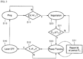
- FIG. 3 shows a process of operating an optical wireless power transfer system of the present disclosure.
- FIG. 4 shows a modulated signal transmitted and received between a transmission module and a reception module.
- FIG. 5 shows each component of an optical wireless power transfer system according to another embodiment of the present disclosure.
- FIG. 6 shows another example of a reception module shown in FIG. 5 .
- an optical wireless power transfer system 1 may include a transmission module 10 and a reception module 20.
- the optical wireless power transfer system 1 shown in FIG. 1 is exemplary, and components of the optical wireless power transfer system 1 are not limited to the embodiment shown in FIG. 1 , and some components of the optical wireless power transfer system 1 may be added, changed, or deleted as necessary.
- the transmission module 10 and the reception module 20 included in the optical wireless power transfer system 1 may be arrayed.
- each module may be arrayed at a preset position with respect to another module and may operate.
- the transmission module 10 may output power light and communication light including a first modulated signal, and may receive reflected light which is generated by reflecting the communication light, and may process a second modulated signal included in the reflected light.
- the transmission module 10 includes a processor that processes a signal and two kinds of light sources that output the power light and the communication light, respectively.
- the reception module 20 may process the first modulated signal included in the communication light output by the transmission module 10, and may reflect the communication light, and may output the reflected light. At this time, the reception module 20 may enable the second modulated signal to be included in the reflected light based on power generated by the power light output by the transmission module 10.
- the reception module 20 may include a processor that processes a signal, a reflector that reflects communication light, and an optical generator that generates power using the power light.
- optical wireless power transfer system 1 according to an embodiment of the present disclosure is described below in detail with reference to FIGS. 2 and 3 .
- the transmission module 10 may include a power light source 11, a communication light source 12, a mirror 13, a beam splitter 14, and a first light source, a transmitting processor 16, an optical absorber 17, and first magnetic bodies 18a and 18b.
- the reception module 20 may include a photoelectric cell 21, a retro-reflector 22, a second photodiode 23, a receiving processor 24, and second magnetic bodies 25a, 25b, a regulator 26, and a decoder 27.
- the transmission module 10 and the reception module 20 shown in FIG. 2 are exemplary, and components of the transmission module 10 and the reception module 20 are not limited to the embodiment shown in FIG. 2 , and some components may be added, changed or deleted as necessary.
- a power light source 11 and a communication light source 12 of the transmission module 10 may output power light and communication light, respectively.
- the power light and the communication light may perform functions, respectively. More specifically, the power light may be output by the transmission module 10 to provide the reception module 20 with the power, and communication light may be output by the transmission module 10 to provide the reception module 20 with a specific signal.
- At least one of lens 11a, 12a may be further provided at an output end of the power light source 11 and an output end of the communication light source 12 to increase a light-transmission efficiency of each of the power light and the communication light, and the lenses 11a and 12a may be operated as a beam expander, a collimator, and the like.
- the mirror 13 of the transmission module 10 may pass the power light and may reflect the communication light.
- the mirror 13 may pass the power light output by the power light source 11 without change. Further, the mirror 13 may reflect the communication light output by the communication light source 12 toward the reception module 20.
- the mirror 13 is a reflector in which a hole is provided to pass the power light, and may have a predetermined angle between the communication light 12 and the reception module 20.
- a portion of the communication light output by the communication light source 12 may pass through the hole provided in the mirror 13.
- the optical absorber 17 of the transmission module 10 may be placed on an extension line connecting the communication light source 12 and the hole to absorb the communication light that has passed through the hole provided in the mirror 13.
- the transmitting processor Tx 16 of the transmission module 10 may control the communication light source 12 to enable the first modulated signal to be included in the communication light.
- the modulated signal (the first modulated signal and the second modulated signal) may refer to all kinds of signals transmitted and received between the transmission module 10 and the reception module 20.
- the transmitting processor 16 may control the first modulated signal to be included in the communication light through an on-off keying method, an intensity modulation (IM) method, and the like, and the method of generating the modulated signal is described below.
- IM intensity modulation
- the photoelectric cell 21 of the reception module 20 may receive the power light to generate the power.
- the photoelectric cell 21 may be any element through which a current flows when light is received and may include a solar cell.
- the photoelectric cell 21 may receive the power light output by the power light source 11 to generate the power based on the intensity of the light. As the power light output by the power light source 11 goes straight through the hole of the mirror 13 described above, the power light source 11 and the photoelectric cell 21 may be placed in the straight line.
- the photoelectric cell 21 may be connected to the regulator 26, and the regulator 26 may convert the power generated by the photoelectric cell 21 into a predetermined voltage and provides the receiving processor Rx Processor 24 with the predetermined voltage. Accordingly, the receiving processor 24 may be powered by the power generated by the photoelectric cell 21.
- the second photodiode 23 of the reception module 20 may convert the communication light into an electric signal. Further, the receiving processor 24 may identify the first modulated signal based on the electrical signal converted by the second photodiode 23 and may process the identified first modulated signal.
- the photodiodes may be any semiconductor diodes that convert light energy into electrical signals.
- Such a photodiode may be a single element, or may have an array form in which a plurality of elements are regularly arranged.
- the second photodiode 23 may convert the communication light output by the communication light source 12 into the electric signal based on the intensity of the light.
- the decoder 27 connected to the second photodiode 23 may convert the electrical signal output by the photodiode into a digital signal and may provide the receiving processor 24 with the converted digital signal.
- the receiving processor 24 may identify the transmitted first modulated signal included in the communication light based on the digital signal provided by the second photodiode 23 and the decoder 27.
- the receiving processor 24 may process the identified first modulated signal. More specifically, the receiving processor 24 may generate a control signal based on the first modulated signal or generate a response signal corresponding to the first modulated signal. Further, the receiving processor 24 may perform various kinds of operations to process a signal.
- the retro-reflector 22 of the reception module 20 may retro-reflect the communication light to output the reflected light.
- the retro-reflector 22 may output the reflected light by reflecting the incident communication light in a direction opposite to an incident direction. To this end, as shown in FIG. 2 , the retro-reflector 22 may be placed in the straight line with respect to the incidence direction of the communication light.
- the receiving processor 24 may control the retro-reflector 22 to enable the second modulated signal to be included in the reflected light based on the power generated by the photoelectric cell 21.
- the receiving processor 24 may control the second modulated signal to be reflected on the reflected light through the on-off keying method and the method of generating the modulated signal is described below.
- the mirror 13 of the above-described transmission module 10 may reflect the reflected light. More specifically, as shown in FIG. 2 , the mirror 13 may reflect the reflected light output by the retro-reflector 22 toward the communication light source 12.
- the beam splitter 14 of the transmission module 10 may reflect back the reflected light, which has been reflected by the mirror 13.
- the beam splitter 14 may be provided between the mirror 13 and the communication light source 12 to pass a portion of the incident light and reflect other portions of the incident light. Accordingly, the communication light incident on the mirror 13 may be output by the communication light source 12 and passes through the beam splitter 14.
- the light is reflected by the mirror 13 and is incident toward the communication light source 12 and the beam splitter 14 may reflect again the above-mentioned light toward the first light diode 15.
- the first photodiode 15 may convert the reflected light, which has been reflected back by the beam splitter 14 into an electrical signal based on the intensity of the light.
- the electrical signal converted as described above may be provided to the transmitting processor 16. Meanwhile, as described above, a decoder may be used to convert the electrical signal converted by the first photodiode 15 into the digital signal.
- the transmitting processor 16 may identify the second modulated signal included in the reflected light based on the electrical signal provided through the first photodiode 15, and may perform various kinds of operations to process the signal based on the identified second modulated signal.
- the transmission module 10 and the reception module 20 may perform the communication and the power transmission using the light that goes straight. Accordingly, each module may be required to be arrayed at a preset position with respect to another module to be operated.
- the transmission module 10 may determine whether the reception module 20 is arrayed at a preset position in a ping mode (S10).
- the transmission module 10 may output the communication light having a reference intensity and may determine whether the intensity of the received reflected light is greater than or equal to the reference intensity.
- the transmission module 10 may output communication light having the reference intensity, in a form of a continuous wave in the ping mode (S10).
- the communication light may not be reflected by the reception module 20 and thus the reflected light may not be received at the transmission module 10.
- the transmission module 10 and the reception module 20 are arrayed, the communication light may be reflected by the reception module 20 and thus the reflected light may be received at the transmission module 10.
- the transmission module 10 may determine that, when the intensity of the received reflected light is equal to or greater than a reference intensity, the reception module 20 is arrayed at the preset position, and may determine that, when the intensity of the received reflected light is less than the reference intensity, the reception module 20 is not arrayed at the preset position.
- the transmission module 10 may determine whether the reception module 20 is arrayed based on comparison of the magnitude of voltage generated based on the reflected light with the reference voltage (S11).
- the reflected light output by a retro-reflector 22 may be received at the first photodiode 15.
- the reflected light received at the first photodiode 15 may be converted into a voltage V i having a predetermined magnitude based on the intensity thereof, and the transmitting processor 16 may compare a total of voltages ⁇ V i converted by the first photodiode 15 with a reference voltage V ref .
- the transmitting processor 16 may determine that, when the total of the voltages ⁇ V i converted by the first diode 15 is equal to or greater than the reference voltage V ref , the reception module 20 is arrayed at the preset position. To the contrary, the transmitting processor 16 may determine that, when the total of voltages ⁇ V i converted by the first light diode 15 is less than the reference voltage V ref , the reception module 20 is not arrayed at the preset position.
- the transmission module 10 may output the above-mentioned power light and may enable the first modulated signal to be included in the communication light.
- the transmission module 10 outputs only communication light having a reference intensity in a form of continuous wave without outputting the power light, and may output the power light and may output the communication light including the first modulated signal, when it is determined that the reception module 20 is arrayed at the preset position.
- the transmission module 10 and the reception module 20 include first and second magnetic bodies 18a, 18b, 25a, and 25b, respectively, to maintain the above-mentioned array state.
- a plurality of first magnetic bodies 18a and 18b and a plurality of second magnetic bodies 25a and 25b may be provided, respectively, and an attraction is generated between the first magnetic bodies 18a and 18b and the second magnetic bodies 25a and 25b.
- the transmission module 10 may include a plurality of first magnetic bodies 18a and 18b
- the reception module 20 may also include a plurality of second magnetic bodies 25a and 25b.
- surfaces facing each other, of the first magnetic bodies 18a and 18b and the second magnetic bodies 25a and 25b may have different polarities, and accordingly, the attraction may occur between the first magnetic bodies 18a and 18b and the second magnetic bodies 25a.
- the attraction may enable the transmission module 10 and the reception module 20 to be fixed within a predetermined distance.
- a light transmitting material such as plastic or glass
- positions of the transmission module 10 and the reception module 20 may be fixed at both ends of the light transmitting material, respectively, based on the attraction generated between the first magnetic bodies 18 and 18b and the second magnetic bodies 25a and 25b.
- the array state may be maintained by the above-described magnetic bodies 18a, 18b, 25a, and 25b unless an external force having a predetermined magnitude or more is applied.
- the optical wireless power transfer system 1 may operate in a negotiation mode (S20).
- the transmission module 10 may gradually increase, until when a completion message is received from the reception module 20, the magnitude of the power light and may output the power light.
- the reception module 20 may generate a second modulated signal including the completion message when the power generated by the power light is greater than or equal to the required power P req .
- the photoelectric cell 21 may receive the power light a magnitude of which is gradually increased and output and may generate the power P out .
- the receiving processor 24 may compare the magnitude of the generated power P out with the magnitude of the required power P req (S21).
- the receiving processor 24 may generate the second modulated signal including the completion message. Subsequently, the receiving processor 24 may control the retro-reflector 22 to enable the second modulated signal including the completion message, to be included in the reflected light.
- the transmitting processor 16 may process the second modulated signal included in the reflected light to identify the completion message, and when the completion message is identified, the transmitting processor 16 may maintain a predetermined magnitude of the power light.
- the receiving processor 24 may generate the second modulated signal including the request message. Subsequently, the receiving processor 24 may control the retro-reflector 22 to enable the second modulated signal to be included in the reflected light, and the second modulated signal includes the request message.
- the output operation of the request message may be performed during a preset period of time.
- the transmitting processor 16 may gradually increase the magnitude of the power light every time the request message is received.
- the transmitting processor 16 may process the second modulated signal included in the reflected light to identify the request message and gradually increase the magnitude of the power light every time the request message is identified.
- the optical wireless power transfer system 1 may perform in a power transfer mode (S30).
- operation of transferring power may be performed through the power light output by the transmission module 10 and operation of transmitting and receiving a signal may be performed through the communication light and the reflected light output by the transmission module 10 and the reception module 20.
- the reception module 20 may generate a second modulated signal including a message of the received power Mr during a reference period of time.
- the transmission module 10 may block the output of power light (Laser Off) (S40).
- the receiving processor 24 may generate the second modulated signal including the message of the receive power Mr during the reference period of time Tm.
- the receiving processor 24 may control the retro-reflector 22 to enable the second modulated signal to be included in the reflected light and the second modulated signal includes the message of the receiver power Mr.
- the second modulated signal including the message of the received power Mr may also be output through the reflected light during the reference period of time Tm (S31).
- the transmitting processor 16 may identify the message of the received power Mr by processing the second modulated signal included in the reflected light, and may continuously output the power light and the communication light when the message of the received power Mr is identified.
- the transmission module 10 may receive the message of the received power Mr during a predetermined period of time Tr for which the message of the received power is received.
- the second modulated signal including the message of the received power Mr is output during the reference period of time Tm, the message of the received power Mr may be received at the transmitting module 10 during the same period of time Tr for which the message of the received power is received.
- the power light may not be received at the photoelectric cell 21 of the reception module 20, and accordingly, the receiving processor 24 may not generate the second modulated signal including the message of the received power Mr. Further, when the array state is not maintained, even if the second modulated signal is generated, the reflected light including the second modulated signal may not be received at the transmission module 10.
- the transmission module 10 may compare the period of time Tr for which the message of the received power Mr is received with a preset time T ref (S32), and as a result of comparison, the transmission module 10 may block, when the period of time Tr for which the message of the received power Mr is received exceeds a preset time T ref , the output of the power light.
- the preset time T ref may be set longer than the aforementioned reference period of time Tm.
- the transmission module 10 may operate in the ping mode S10 described above to output communication light having the reference intensity. As the operation process after the ping mode S10 has been described above, a detailed description thereof is omitted.
- the modulated signals output by the transmission module 10 and the reception module 20 are described below with reference to FIG. 4 .
- the transmission module 10 may adjust the intensity of the communication light and output the communication light, and the reception module 20 may identify the first modulated signal based on the intensity of the communication light.
- the transmitting processor 16 may control the first modulated signal to be included in the communication light through the on-off keying method, the intensity modulation (IM) method, and the like.
- IM intensity modulation
- the reception module 20 outputs the reflected light including the second modulated signal by reflecting the communication light.
- the communication light may have a continuous output.
- the first modulated signal is preferably included in the communication light through the IM method.
- the transmitting processor 16 may adjust the intensity of communication light through the IM method to transmit a first modulated signal including bits of '101001'. More specifically, the communication light may have different intensities corresponding to bits 1 and 0, respectively, and the transmitting processor 16 adjusts the intensity of the communication light to include the first modulated signal, which is a combination of bits 1 and 0, in the communication light.
- the second photodiode 23 of the reception module 20 may generate an electrical signal based on the intensity of the communication light, and the receiving processor 24 may identify the first modulated signal included in the communication light as ' 101001' based on the magnitude of the electrical signal.
- the reception module 20 may reflect the communication light through the on-off keying method and may output the reflected light including the second modulated signal.
- the receiving processor 24 may control a reflection operation of the retro-reflector 22 through the on-off keying method to transmit a second modulated signal including bits of '101011'.
- the receiving processor 24 may control the retro-reflector 22 to perform the reflection operation during the period of time corresponding to bit 1, and may control the retro-reflector 22 not to perform the reflection operation during the period of time corresponding to bit 0.
- the reflected light may be output only during the period of time corresponding to bit 1.
- the intensity of the reflected light output may be proportional to the intensity of the communication light.
- the first photodiode 15 of the transmission module 10 may generate the electrical signal based on the intensity of the reflected light, and the transmitting processor 16 may identify a second modulation included in the reflected light, as '101011', based on the magnitude of the electrical signal.
- An optical wireless power transfer system 1' according to another embodiment of the present disclosure is described below in detail with reference to FIGS. 5 and 6 .
- the optical wireless power transfer system 1' may include a transmission module 10' and a reception module 20' arrayed with respect to the transmission module 10'.
- the transmission module 10' may output the main light including the first modulated signal and may receive the reflected light generated by reflecting a portion of the main light, and process the second modulated signal included in the reflected light.
- the transmission module 10' may include a processor that processes a signal and a single light source that outputs the main light.
- the reception module 20' may process the first modulated signal included in the main light and may reflect a portion of the main light to output the reflected light, and may enable the second modulated signal to be included in the reflected light based on the power generated due to the main light.
- the reception module 20' may include a processor that processes a signal, a reflector that reflects a portion of the main light, and an optical generator that generates power using the main light.
- a transmission module 10' includes a main light source 11', a beam splitter 12', a first photodiode 13', and a transmitting processor 14', an optical absorber 16', and first magnetic bodies 15a' and 15b'.
- the reception module 20' may include a photoelectric cell 21', a retro-reflector 22', a second photodiode 23', a receiving processor 24', and the second magnetic bodies 25a' and 25b', a regulator 26', and a decoder 27'.
- the transmission module 10' and the reception module 20' shown in FIGS. 5 and 6 are exemplary, and components of the transmission module 10' and the reception module 20' are not limited to the embodiment shown in FIG. 2 , and some components of the transmission module 10' and the reception module 20' may be added, changed or deleted as necessary.
- each component shown in FIGS. 5 and 6 may be the same as described with reference to FIG. 2 .
- the beam splitter 12', the first photodiode 13', the transmitting processor 14', and the first magnetic bodies 15a' and 15b' and the optical absorber 16' included in the transmission module 10' shown in FIGS. 5 and 6 may have the same functions as the beam splitter 14, the first photodiode 15, the transmitting processor 16, the first magnetic bodies 18a and 18b, and the optical absorber shown in FIG. 2 , respectively.
- the transmission module 10' has a less number of light sources than the transmission module 10 shown in FIG. 2 .
- All other configurations, except for the omitted configurations, may be the same as configurations as shown in FIG. 2 due to the reduced number of light sources.
- each component included in the reception module 20 shown in FIGS. 5 and 6 may be the same as described with reference to FIG. 2 .
- the photoelectric cell 21', the retro-reflector 22', the second photodiode 23', the receiving processor 24', and the second magnetic bodies 25a' and 25b', the regulartor 26' and the decoder 27' included in the reception module 20' shown in FIGS. 5 and 6 may have the same functions as the photoelectric cell 21, the retro-reflector 22, the second photodiode 23 and the receiving processor 24, the second magnetic bodies 25a and 25b, the regulator 26 and the decoder 27 shown in FIG. 2 , respectively.
- a main light source 11' of the transmission module 10' may output the main light.
- the main light may include both the power light and the communication light described with reference to FIG. 2 with respect to the function thereof. More specifically, the main light may enable the power to be provided to the reception module 20' and may be output to provide the reception module 20' with a specific signal.
- the main light may include the power light output from a center portion thereof and communication light output from a peripheral portion thereof.
- the beam splitter 12'of the transmission module 10' may pass the main light.
- the beam splitter 12' may be provided between the main light source 11' and the reception module 20' to pass a portion of incident light and reflect other portions of the incident light. Accordingly, the main light incident on the reception module 20' may be output by the main light source 11' and may pass through the beam splitter 12.
- the transmitting processor 14' of the transmission module 10' may control the main light source 11' to enable the first modulated signal to be included in the main light. More specifically, the transmitting processor 14' may adjust the intensity of the main light and may output the main light having the adjusted intensity to control the first modulated signal to be included in the main light.
- the photoelectric cell 21'of the reception module 20' may receive the main light to generate the power. To this end, the main light source 11' of the transmission module 10' and the photoelectric cell 21'of the reception module 20' may be placed in a straight line.
- the regulator 26' may convert the power generated by the photoelectric cell 21' into a predetermined voltage and may provide the receiving processor 24' with the predetermined voltage, and accordingly, the receiving processor 24' may receive the power based on the power generated by the photoelectric cell 21'.
- the second photodiode 23' of the reception module 20' may convert a portion of the main light into an electrical signal. More specifically, the second photodiode 23' may receive a portion of the main light according to position thereof and may convert the portion of the main light into the electrical signal.
- the decoder 27' may convert the converted electrical signal into a digital signal and provide the receiving processor 24' with the converted digital signal.
- the receiving processor 24' may identify the first modulated signal based on the electrical signal converted by the second photodiode 23' and may process the identified first modulated signal. More specifically, the receiving processor 24' may identify the first modulated signal based on the intensity of the main light.
- the retro-reflector 22' of the reception module 20' may retro-reflect a portion of the main light to output the reflected light. More specifically, the retro-reflector 22' may retro-reflect a portion of the main light according to the position thereof, and to this end, the retro-reflector 22' may be placed in the straight line with respect to the incident direction of the main light.
- the receiving processor 24' may control the retro-reflector 22' to enable the second modulated signal to be included in the reflected light based on the power generated by the photocell 21'.
- the method of including the second modulated signal in the reflected light is the same as the method described with reference to FIG. 4 , a detailed description thereof is omitted.
- the beam splitter 12' of the above-described transmission module 10' may reflect the reflected light. More specifically, as shown in FIGS. 5 and 6 , the beam splitter 12' may reflect a portion of the reflected light output by the retro-reflector 22' toward the first photodiode 13.
- the first photodiode 13' may convert the reflected light reflected by the beam splitter 12' into the electrical signal based on the intensity of the light, and the converted electrical signal may be provided to the transmitting processor 14'.
- the transmitting processor 14' may identify the second modulated signal included in the reflected light based on the electrical signal provided through the first photodiode 13' and may perform operation of processing various kinds of signals based on the identified second modulated signal.
- the photoelectric cell 21', the retro-reflector 22', and the second photodiode 23' may be provided at any position such that the photoelectric cell 21', the retro-reflector 22', and the second photodiode 23' may receive the main light. More specifically, the retro-reflector 22'and the second photodiode 23' may be arbitrarily arranged in the region where the main light is received.
- the retro-reflector 22' may be provided at a center of the region where the main light is received, and a plurality of cells included in the photoelectric cell 21' and the second photodiode 23' may have a circular shape or rectangular matrix shape with respect to the retro-reflector 22'.
- the retro-reflector 22', the second photodiode 23', the plurality of cells included in the photoelectric cell 21' may have any arrangement within the circular shape or the rectangular matrix shape.
- wireless bidirectional communication is performed using the light, thereby increasing the possible distance to perform the communication between terminals.
- additional battery may not be mounted on the wireless terminal using the light as the power source, thereby reducing the volume and the weight of the terminal.
- the modulated signal may be transmitted and received through the light, thereby preventing the electro magnetic interference (EMI) generated by peripheral electronic devices.
- EMI electro magnetic interference
Landscapes
- Engineering & Computer Science (AREA)
- Computer Networks & Wireless Communication (AREA)
- Physics & Mathematics (AREA)
- Electromagnetism (AREA)
- Signal Processing (AREA)
- Power Engineering (AREA)
- Optics & Photonics (AREA)
- Optical Communication System (AREA)
Description
- An optical wireless power transfer system performing wireless bidirectional communication using light is disclosed herein.
- Recently, in a home appliance market, a main body that performs a main function and a wireless terminal capable of performing an additional function in conjunction with the main body may be provided together.
- For example, in the cooktop market, which has recently greatly increased in size, the cooktop may include a main body that performs a function for heating food, and a detachable knob switch that may be removably attached to the main body and may perform additional functions for adjusting intensity of heating.
- However, the wireless terminal provided as described above may require an additional battery to perform wireless communication with the main body, and a volume and a weight of the wireless terminal may be increased because the battery is mounted on the wireless terminal.
- Further, as the battery is discharged over time, users may not only periodically replace the battery of the wireless terminal, but also a required function may not be performed through the wireless terminal when the battery is discharged in unexpected situations.
-
EP 3 076 201 A1 relates to a network node, network controller node and methods for supporting communication with user equipment within a wireless telecommunication network. The network node comprises: an antenna for receiving and transmitting wireless telecommunication communication signals to a user equipment, said wireless telecommunication signals being within a first frequency band. A receiver for receiving an electromagnetic signal transmitted wirelessly from a network controller node within said wireless telecommunication network, said electromagnetic signal being within a second frequency band, said second frequency band being a different frequency band to said first frequency band, said receiver comprising a retro-reflector for reflecting said electromagnetic signal back towards said network controller node. The network node further comprising a modulator operable to modulate at least one property of said electromagnetic signal in dependence upon said signal received from said user equipment such that information received from user equipment is conveyed via modulations in said reflected electromagnetic signal to said network controller node. - The invention is specified by the independent claims. Preferred embodiments are defined in the dependent claims.
- The present disclosure provides an optical wireless power transfer system that performs wireless bidirectional communication using light.
- The present disclosure further provides an optical wireless power transfer system using light as a power source.
- The present disclosure also provides an optical wireless power transfer system that transmits and receives a modulated signal through light.
- The objects of the present disclosure are not limited to the above-mentioned objects, and other objects and advantages of the present disclosure which are not mentioned may be understood by the following description and more clearly understood by the embodiments of the present disclosure. It will also be readily apparent that the objects and the advantages of the present disclosure may be implemented by features defined in claims and a combination thereof.
- According to the present disclosure, the optical wireless power transfer system may include a transmission module that outputs communication light or main light and receives a reflected light and processes a modulated signal included in the reflected light, and the reception module that processes the modulated signal included in the communication light or the main light and reflects the communication light or the main light and outputs the reflected light, to perform the wireless bidirectional communication using the light.
- Further, according to the present disclosure, the optical wireless power transfer system may include the transmission module that outputs the power light or the main light and the reception module that receives the power light or the main light to generate the power and enables the modulated signal to be included in the reflected light based on the generated power, to use the light as the power source.
- Further, according to the present disclosure, the optical wireless power transfer system may include the transmission module that adjusts the intensity of the communication light or the main light and output the communication light or the main light and the reception module that identifies the modulated signal based on the intensity of the communication light or the main light, to transmit and receive the modulated signal through the light.
- According to the present disclosure, the wireless bidirectional communication is performed using the light, thereby increasing a possible distance to perform communication between terminals.
- Further, according to the present disclosure, additional battery may not be mounted on the wireless terminal using the light as the power source, thereby reducing the volume and the weight of the terminal.
- Further, according to the present disclosure, the modulated signal may be transmitted and received through the light, thereby preventing electro magnetic interference (EMI) that occurs based on periphery electronic devices.
-
FIG. 1 shows an optical wireless power transfer system of the present disclosure. -
FIG. 2 shows each component of an optical wireless power transfer system according to an embodiment of the present disclosure. -
FIG. 3 shows a process of operating an optical wireless power transfer system of the present disclosure. -
FIG. 4 shows a modulated signal transmitted and received between a transmission module and a reception module. -
FIG. 5 shows each component of an optical wireless power transfer system according to another embodiment of the present disclosure. -
FIG. 6 shows another example of a reception module shown inFIG. 5 . - The above-mentioned objects, features, and advantages of the present disclosure will be described in detail with reference to the accompanying drawings. Accordingly, the skilled person in the art to which the present disclosure pertains may easily implement the technical idea of the present disclosure. In the description of the present disclosure, if it is determined that the detailed description of a well-known technology related to the present disclosure may unnecessarily obscure the gist of the present disclosure, the detailed description thereof is omitted. Preferred embodiments of the present disclosure are described in detail with reference to the accompanying drawings. In the drawings, same reference numerals are used to refer to same or similar components.
- The present disclosure relates to an optical wireless power transfer system capable of performing bidirectional communication wirelessly using light.
- Hereinafter, the optical wireless power transfer system of the present disclosure will be described in detail with reference to
FIGS. 1 to 6 . -
FIG. 1 shows an optical wireless power transfer system of the present disclosure. -
FIG. 2 shows each component of an optical wireless power transfer system according to an embodiment of the present disclosure, andFIG. 3 shows a process of operating an optical wireless power transfer system of the present disclosure. -
FIG. 4 shows a modulated signal transmitted and received between a transmission module and a reception module. -
FIG. 5 shows each component of an optical wireless power transfer system according to another embodiment of the present disclosure.FIG. 6 shows another example of a reception module shown inFIG. 5 . - Referring to
FIG. 1 , according to the present disclosure, an optical wirelesspower transfer system 1 may include atransmission module 10 and areception module 20. The optical wirelesspower transfer system 1 shown inFIG. 1 is exemplary, and components of the optical wirelesspower transfer system 1 are not limited to the embodiment shown inFIG. 1 , and some components of the optical wirelesspower transfer system 1 may be added, changed, or deleted as necessary. - As shown in
FIG. 1 , thetransmission module 10 and thereception module 20 included in the optical wirelesspower transfer system 1 may be arrayed. In other words, each module may be arrayed at a preset position with respect to another module and may operate. - A method in which each module is arrayed and a method of determining, by the
transmission module 10, a state in which modules are arrayed are described below. - The
transmission module 10 may output power light and communication light including a first modulated signal, and may receive reflected light which is generated by reflecting the communication light, and may process a second modulated signal included in the reflected light. - To this end, the
transmission module 10 includes a processor that processes a signal and two kinds of light sources that output the power light and the communication light, respectively. - Meanwhile, the
reception module 20 may process the first modulated signal included in the communication light output by thetransmission module 10, and may reflect the communication light, and may output the reflected light. At this time, thereception module 20 may enable the second modulated signal to be included in the reflected light based on power generated by the power light output by thetransmission module 10. - To this end, the
reception module 20 may include a processor that processes a signal, a reflector that reflects communication light, and an optical generator that generates power using the power light. - The optical wireless
power transfer system 1 according to an embodiment of the present disclosure is described below in detail with reference toFIGS. 2 and3 . - Referring to
FIG. 2 , according to an embodiment of the present disclosure, thetransmission module 10 may include apower light source 11, acommunication light source 12, amirror 13, abeam splitter 14, and a first light source, a transmittingprocessor 16, anoptical absorber 17, and firstmagnetic bodies - Meanwhile, according to an embodiment of the present disclosure, the
reception module 20 may include aphotoelectric cell 21, a retro-reflector 22, asecond photodiode 23, areceiving processor 24, and secondmagnetic bodies regulator 26, and adecoder 27. - The
transmission module 10 and thereception module 20 shown inFIG. 2 are exemplary, and components of thetransmission module 10 and thereception module 20 are not limited to the embodiment shown inFIG. 2 , and some components may be added, changed or deleted as necessary. - Hereinafter, a path of light output by the optical wireless
power transfer system 1 according to an embodiment of the present disclosure is described below in detail with reference toFIG. 2 . - A
power light source 11 and acommunication light source 12 of thetransmission module 10 may output power light and communication light, respectively. - In the present disclosure, the power light and the communication light may perform functions, respectively. More specifically, the power light may be output by the
transmission module 10 to provide thereception module 20 with the power, and communication light may be output by thetransmission module 10 to provide thereception module 20 with a specific signal. - At least one of
lens power light source 11 and an output end of thecommunication light source 12 to increase a light-transmission efficiency of each of the power light and the communication light, and thelenses - The
mirror 13 of thetransmission module 10 may pass the power light and may reflect the communication light. - More specifically, the
mirror 13 may pass the power light output by thepower light source 11 without change. Further, themirror 13 may reflect the communication light output by thecommunication light source 12 toward thereception module 20. - To this end, as shown in
FIG. 2 , themirror 13 is a reflector in which a hole is provided to pass the power light, and may have a predetermined angle between thecommunication light 12 and thereception module 20. - Meanwhile, a portion of the communication light output by the
communication light source 12 may pass through the hole provided in themirror 13. Theoptical absorber 17 of thetransmission module 10 may be placed on an extension line connecting thecommunication light source 12 and the hole to absorb the communication light that has passed through the hole provided in themirror 13. - The transmitting
processor Tx 16 of thetransmission module 10 may control thecommunication light source 12 to enable the first modulated signal to be included in the communication light. - In the present disclosure, the modulated signal (the first modulated signal and the second modulated signal) may refer to all kinds of signals transmitted and received between the
transmission module 10 and thereception module 20. - The transmitting
processor 16 may control the first modulated signal to be included in the communication light through an on-off keying method, an intensity modulation (IM) method, and the like, and the method of generating the modulated signal is described below. - The
photoelectric cell 21 of thereception module 20 may receive the power light to generate the power. Thephotoelectric cell 21 may be any element through which a current flows when light is received and may include a solar cell. - The
photoelectric cell 21 may receive the power light output by thepower light source 11 to generate the power based on the intensity of the light. As the power light output by thepower light source 11 goes straight through the hole of themirror 13 described above, thepower light source 11 and thephotoelectric cell 21 may be placed in the straight line. - As shown in
FIG. 2 , thephotoelectric cell 21 may be connected to theregulator 26, and theregulator 26 may convert the power generated by thephotoelectric cell 21 into a predetermined voltage and provides the receivingprocessor Rx Processor 24 with the predetermined voltage. Accordingly, the receivingprocessor 24 may be powered by the power generated by thephotoelectric cell 21. - Meanwhile, the
second photodiode 23 of thereception module 20 may convert the communication light into an electric signal. Further, the receivingprocessor 24 may identify the first modulated signal based on the electrical signal converted by thesecond photodiode 23 and may process the identified first modulated signal. - In the present disclosure, the photodiodes (a
first photodiode 15 and a second photodiode 23) may be any semiconductor diodes that convert light energy into electrical signals. Such a photodiode may be a single element, or may have an array form in which a plurality of elements are regularly arranged. - The
second photodiode 23 may convert the communication light output by thecommunication light source 12 into the electric signal based on the intensity of the light. Thedecoder 27 connected to thesecond photodiode 23 may convert the electrical signal output by the photodiode into a digital signal and may provide the receivingprocessor 24 with the converted digital signal. - The receiving
processor 24 may identify the transmitted first modulated signal included in the communication light based on the digital signal provided by thesecond photodiode 23 and thedecoder 27. - The receiving
processor 24 may process the identified first modulated signal. More specifically, the receivingprocessor 24 may generate a control signal based on the first modulated signal or generate a response signal corresponding to the first modulated signal. Further, the receivingprocessor 24 may perform various kinds of operations to process a signal. - Meanwhile, the retro-
reflector 22 of thereception module 20 may retro-reflect the communication light to output the reflected light. - More specifically, the retro-
reflector 22 may output the reflected light by reflecting the incident communication light in a direction opposite to an incident direction. To this end, as shown inFIG. 2 , the retro-reflector 22 may be placed in the straight line with respect to the incidence direction of the communication light. - At this time, the receiving
processor 24 may control the retro-reflector 22 to enable the second modulated signal to be included in the reflected light based on the power generated by thephotoelectric cell 21. - The receiving
processor 24 may control the second modulated signal to be reflected on the reflected light through the on-off keying method and the method of generating the modulated signal is described below. - The
mirror 13 of the above-describedtransmission module 10 may reflect the reflected light. More specifically, as shown inFIG. 2 , themirror 13 may reflect the reflected light output by the retro-reflector 22 toward thecommunication light source 12. - The
beam splitter 14 of thetransmission module 10 may reflect back the reflected light, which has been reflected by themirror 13. - The
beam splitter 14 may be provided between themirror 13 and thecommunication light source 12 to pass a portion of the incident light and reflect other portions of the incident light. Accordingly, the communication light incident on themirror 13 may be output by thecommunication light source 12 and passes through thebeam splitter 14. - As shown in
FIG. 2 , the light is reflected by themirror 13 and is incident toward thecommunication light source 12 and thebeam splitter 14 may reflect again the above-mentioned light toward thefirst light diode 15. - The
first photodiode 15 may convert the reflected light, which has been reflected back by thebeam splitter 14 into an electrical signal based on the intensity of the light. The electrical signal converted as described above may be provided to the transmittingprocessor 16. Meanwhile, as described above, a decoder may be used to convert the electrical signal converted by thefirst photodiode 15 into the digital signal. - The transmitting
processor 16 may identify the second modulated signal included in the reflected light based on the electrical signal provided through thefirst photodiode 15, and may perform various kinds of operations to process the signal based on the identified second modulated signal. - Hereinafter, a method of communicating, by the transmission module and the
reception module 20 and a method of transmitting the power are described below in detail with reference toFIGS. 2 and3 . - As described above, the
transmission module 10 and thereception module 20 may perform the communication and the power transmission using the light that goes straight. Accordingly, each module may be required to be arrayed at a preset position with respect to another module to be operated. - Referring to
FIG. 3 , in order to determine the above-described array state of modules, thetransmission module 10 may determine whether thereception module 20 is arrayed at a preset position in a ping mode (S10). - More specifically, the
transmission module 10 may output the communication light having a reference intensity and may determine whether the intensity of the received reflected light is greater than or equal to the reference intensity. - The
transmission module 10 may output communication light having the reference intensity, in a form of a continuous wave in the ping mode (S10). - In this case, when the
transmission module 10 and thereception module 20 are not arrayed, the communication light may not be reflected by thereception module 20 and thus the reflected light may not be received at thetransmission module 10. To the contrary, when thetransmission module 10 and thereception module 20 are arrayed, the communication light may be reflected by thereception module 20 and thus the reflected light may be received at thetransmission module 10. - The
transmission module 10 may determine that, when the intensity of the received reflected light is equal to or greater than a reference intensity, thereception module 20 is arrayed at the preset position, and may determine that, when the intensity of the received reflected light is less than the reference intensity, thereception module 20 is not arrayed at the preset position. - For example, the
transmission module 10 may determine whether thereception module 20 is arrayed based on comparison of the magnitude of voltage generated based on the reflected light with the reference voltage (S11). - More specifically, when the optical wireless
power transfer system 1 is provided as shown inFIG. 2 , the reflected light output by a retro-reflector 22 may be received at thefirst photodiode 15. The reflected light received at thefirst photodiode 15 may be converted into a voltage Vi having a predetermined magnitude based on the intensity thereof, and the transmittingprocessor 16 may compare a total of voltages ∑Vi converted by thefirst photodiode 15 with a reference voltage Vref. - The transmitting
processor 16 may determine that, when the total of the voltages ∑Vi converted by thefirst diode 15 is equal to or greater than the reference voltage Vref, thereception module 20 is arrayed at the preset position. To the contrary, the transmittingprocessor 16 may determine that, when the total of voltages ∑Vi converted by thefirst light diode 15 is less than the reference voltage Vref, thereception module 20 is not arrayed at the preset position. - When it is determined that the
reception module 20 is arrayed at the preset position, thetransmission module 10 may output the above-mentioned power light and may enable the first modulated signal to be included in the communication light. - In other words, in the ping mode S10, the
transmission module 10 outputs only communication light having a reference intensity in a form of continuous wave without outputting the power light, and may output the power light and may output the communication light including the first modulated signal, when it is determined that thereception module 20 is arrayed at the preset position. - Meanwhile, the
transmission module 10 and thereception module 20 include first and secondmagnetic bodies magnetic bodies magnetic bodies magnetic bodies magnetic bodies - For example, as shown in
FIG. 2 , thetransmission module 10 may include a plurality of firstmagnetic bodies reception module 20 may also include a plurality of secondmagnetic bodies magnetic bodies magnetic bodies magnetic bodies magnetic bodies 25a. - The attraction may enable the
transmission module 10 and thereception module 20 to be fixed within a predetermined distance. For example, when a light transmitting material such as plastic or glass are provided between thetransmission module 10 and thereception module 20, positions of thetransmission module 10 and thereception module 20 may be fixed at both ends of the light transmitting material, respectively, based on the attraction generated between the firstmagnetic bodies 18 and 18b and the secondmagnetic bodies - Accordingly, after the
transmission module 10 and thereception module 20 are arrayed once, the array state may be maintained by the above-describedmagnetic bodies - Referring back to
FIG. 3 , when each module is arrayed, the optical wirelesspower transfer system 1 may operate in a negotiation mode (S20). - In the negotiation mode S20, the
transmission module 10 may gradually increase, until when a completion message is received from thereception module 20, the magnitude of the power light and may output the power light. - Meanwhile, in the negotiation mode S20, the
reception module 20 may generate a second modulated signal including the completion message when the power generated by the power light is greater than or equal to the required power Preq. - Referring to
FIG. 2 , thephotoelectric cell 21 may receive the power light a magnitude of which is gradually increased and output and may generate the power Pout. The receivingprocessor 24 may compare the magnitude of the generated power Pout with the magnitude of the required power Preq (S21). - As a result of comparison, when the magnitude of the generated power Pout is equal to or greater than the magnitude of the required power Preq, the receiving
processor 24 may generate the second modulated signal including the completion message. Subsequently, the receivingprocessor 24 may control the retro-reflector 22 to enable the second modulated signal including the completion message, to be included in the reflected light. - The transmitting
processor 16 may process the second modulated signal included in the reflected light to identify the completion message, and when the completion message is identified, the transmittingprocessor 16 may maintain a predetermined magnitude of the power light. - To the contrary, when the magnitude of the generated power Pout is less than the magnitude of the required power Preq, the receiving
processor 24 may generate the second modulated signal including the request message. Subsequently, the receivingprocessor 24 may control the retro-reflector 22 to enable the second modulated signal to be included in the reflected light, and the second modulated signal includes the request message. The output operation of the request message may be performed during a preset period of time. - The transmitting
processor 16 may gradually increase the magnitude of the power light every time the request message is received. - More specifically, the transmitting
processor 16 may process the second modulated signal included in the reflected light to identify the request message and gradually increase the magnitude of the power light every time the request message is identified. - Referring back to
FIG. 3 , when the power generated by thereception module 20 is greater than or equal to the required power and the negotiation mode S20 is completed, the optical wirelesspower transfer system 1 may perform in a power transfer mode (S30). - In the power transfer mode (S30), operation of transferring power may be performed through the power light output by the
transmission module 10 and operation of transmitting and receiving a signal may be performed through the communication light and the reflected light output by thetransmission module 10 and thereception module 20. - As the operation of transmitting the power and the operation of transmitting and receiving the signal have been described with reference to
FIG. 2 , a detailed description thereof is omitted. - Meanwhile, in the power transmission mode S30, when the power is generated based on the power light, the
reception module 20 may generate a second modulated signal including a message of the received power Mr during a reference period of time. - Further, when the message of the received power Mr is not received for a preset period of time, the
transmission module 10 may block the output of power light (Laser Off) (S40). - Referring to
FIG. 2 , when the power is generated by the power light received at thephotoelectric cell 21 in the power transfer mode S30, the receivingprocessor 24 may generate the second modulated signal including the message of the receive power Mr during the reference period of time Tm. - Subsequently, the receiving
processor 24 may control the retro-reflector 22 to enable the second modulated signal to be included in the reflected light and the second modulated signal includes the message of the receiver power Mr. As the message of the received power Mr is generated during the reference period of time Tm, the second modulated signal including the message of the received power Mr may also be output through the reflected light during the reference period of time Tm (S31). - The transmitting
processor 16 may identify the message of the received power Mr by processing the second modulated signal included in the reflected light, and may continuously output the power light and the communication light when the message of the received power Mr is identified. - When the
transmission module 10 and thereception module 20 are arrayed, thetransmission module 10 may receive the message of the received power Mr during a predetermined period of time Tr for which the message of the received power is received. As the second modulated signal including the message of the received power Mr is output during the reference period of time Tm, the message of the received power Mr may be received at the transmittingmodule 10 during the same period of time Tr for which the message of the received power is received. - At this time, when a change occurs in the position of the
transmission module 10 or thereception module 20 and the above-described array state may not be maintained, the power light may not be received at thephotoelectric cell 21 of thereception module 20, and accordingly, the receivingprocessor 24 may not generate the second modulated signal including the message of the received power Mr. Further, when the array state is not maintained, even if the second modulated signal is generated, the reflected light including the second modulated signal may not be received at thetransmission module 10. - The
transmission module 10 may compare the period of time Tr for which the message of the received power Mr is received with a preset time Tref (S32), and as a result of comparison, thetransmission module 10 may block, when the period of time Tr for which the message of the received power Mr is received exceeds a preset time Tref, the output of the power light. - The preset time Tref may be set longer than the aforementioned reference period of time Tm.
- Further, when the message of the received power Mr is not received within a preset period of time, the
transmission module 10 may operate in the ping mode S10 described above to output communication light having the reference intensity. As the operation process after the ping mode S10 has been described above, a detailed description thereof is omitted. - As described above, when the
transmission module 10 and thereception module 20 do not maintain the array state, operation of determining the array state thereof is automatically performed through operation of blocking the output (S40) and in the ping mode (S10), thereby saving the energy and improving reliability in communication. - The modulated signals output by the
transmission module 10 and thereception module 20 are described below with reference toFIG. 4 . - The
transmission module 10 may adjust the intensity of the communication light and output the communication light, and thereception module 20 may identify the first modulated signal based on the intensity of the communication light. - More specifically, the transmitting
processor 16 may control the first modulated signal to be included in the communication light through the on-off keying method, the intensity modulation (IM) method, and the like. - However, as described above, the
reception module 20 outputs the reflected light including the second modulated signal by reflecting the communication light. To this end, the communication light may have a continuous output. Accordingly, the first modulated signal is preferably included in the communication light through the IM method. - Referring to
FIG. 4 , the transmittingprocessor 16 may adjust the intensity of communication light through the IM method to transmit a first modulated signal including bits of '101001'. More specifically, the communication light may have different intensities corresponding tobits processor 16 adjusts the intensity of the communication light to include the first modulated signal, which is a combination ofbits - As described above, the
second photodiode 23 of thereception module 20 may generate an electrical signal based on the intensity of the communication light, and the receivingprocessor 24 may identify the first modulated signal included in the communication light as ' 101001' based on the magnitude of the electrical signal. - Meanwhile, the
reception module 20 may reflect the communication light through the on-off keying method and may output the reflected light including the second modulated signal. - Referring back to
FIG. 4 , the receivingprocessor 24 may control a reflection operation of the retro-reflector 22 through the on-off keying method to transmit a second modulated signal including bits of '101011'. - More specifically, the receiving
processor 24 may control the retro-reflector 22 to perform the reflection operation during the period of time corresponding tobit 1, and may control the retro-reflector 22 not to perform the reflection operation during the period of time corresponding tobit 0. - Accordingly, as shown in
FIG. 4 , the reflected light may be output only during the period of time corresponding tobit 1. As the reflected light is output by reflecting the communication light, the intensity of the reflected light output may be proportional to the intensity of the communication light. - As described above, the
first photodiode 15 of thetransmission module 10 may generate the electrical signal based on the intensity of the reflected light, and the transmittingprocessor 16 may identify a second modulation included in the reflected light, as '101011', based on the magnitude of the electrical signal. - An optical wireless power transfer system 1' according to another embodiment of the present disclosure is described below in detail with reference to
FIGS. 5 and6 . - According to another embodiment of the present disclosure, as shown in
FIG. 1 , the optical wireless power transfer system 1' may include a transmission module 10' and a reception module 20' arrayed with respect to the transmission module 10'. - The transmission module 10' may output the main light including the first modulated signal and may receive the reflected light generated by reflecting a portion of the main light, and process the second modulated signal included in the reflected light.
- To this end, the transmission module 10' may include a processor that processes a signal and a single light source that outputs the main light.
- Meanwhile, the reception module 20' may process the first modulated signal included in the main light and may reflect a portion of the main light to output the reflected light, and may enable the second modulated signal to be included in the reflected light based on the power generated due to the main light.
- To this end, the reception module 20' may include a processor that processes a signal, a reflector that reflects a portion of the main light, and an optical generator that generates power using the main light.
- Referring to
FIGS. 5 and6 , according to another embodiment of the present disclosure, a transmission module 10' includes a main light source 11', a beam splitter 12', a first photodiode 13', and a transmitting processor 14', an optical absorber 16', and firstmagnetic bodies 15a' and 15b'. - Meanwhile, according to another embodiment of the present disclosure, the reception module 20' may include a
photoelectric cell 21', a retro-reflector 22', a second photodiode 23', a receiving processor 24', and the secondmagnetic bodies 25a' and 25b', a regulator 26', and a decoder 27'. - The transmission module 10' and the reception module 20' shown in
FIGS. 5 and6 are exemplary, and components of the transmission module 10' and the reception module 20' are not limited to the embodiment shown inFIG. 2 , and some components of the transmission module 10' and the reception module 20' may be added, changed or deleted as necessary. - Basically, each component shown in
FIGS. 5 and6 may be the same as described with reference toFIG. 2 . - More specifically, the beam splitter 12', the first photodiode 13', the transmitting processor 14', and the first
magnetic bodies 15a' and 15b' and the optical absorber 16' included in the transmission module 10' shown inFIGS. 5 and6 may have the same functions as thebeam splitter 14, thefirst photodiode 15, the transmittingprocessor 16, the firstmagnetic bodies FIG. 2 , respectively. - That is, as shown in
FIGS. 5 and6 , the transmission module 10' has a less number of light sources than thetransmission module 10 shown inFIG. 2 . All other configurations, except for the omitted configurations, may be the same as configurations as shown inFIG. 2 due to the reduced number of light sources. - Meanwhile, each component included in the
reception module 20 shown inFIGS. 5 and6 may be the same as described with reference toFIG. 2 . In other words, thephotoelectric cell 21', the retro-reflector 22', the second photodiode 23', the receiving processor 24', and the secondmagnetic bodies 25a' and 25b', the regulartor 26' and the decoder 27' included in the reception module 20' shown inFIGS. 5 and6 may have the same functions as thephotoelectric cell 21, the retro-reflector 22, thesecond photodiode 23 and the receivingprocessor 24, the secondmagnetic bodies regulator 26 and thedecoder 27 shown inFIG. 2 , respectively. - Accordingly, light and paths of light different from those described in
FIG. 2 are described below with reference toFIGS. 5 and6 . - A main light source 11' of the transmission module 10' may output the main light.
- In the present disclosure, the main light may include both the power light and the communication light described with reference to
FIG. 2 with respect to the function thereof. More specifically, the main light may enable the power to be provided to the reception module 20' and may be output to provide the reception module 20' with a specific signal. - For example, as shown in
FIG. 5 , the main light may include the power light output from a center portion thereof and communication light output from a peripheral portion thereof. - The beam splitter 12'of the transmission module 10' may pass the main light.
- More specifically, the beam splitter 12' may be provided between the main light source 11' and the reception module 20' to pass a portion of incident light and reflect other portions of the incident light. Accordingly, the main light incident on the reception module 20' may be output by the main light source 11' and may pass through the
beam splitter 12. - The transmitting processor 14' of the transmission module 10' may control the main light source 11' to enable the first modulated signal to be included in the main light. More specifically, the transmitting processor 14' may adjust the intensity of the main light and may output the main light having the adjusted intensity to control the first modulated signal to be included in the main light.
- As a method of including the first modulated signal in the main light by adjusting the intensity of the light is the same as the method of including the first modulated signal in the communication light described with reference to
FIG. 4 , a detailed description thereof is omitted. - The photoelectric cell 21'of the reception module 20' may receive the main light to generate the power. To this end, the main light source 11' of the transmission module 10' and the photoelectric cell 21'of the reception module 20' may be placed in a straight line.
- The regulator 26' may convert the power generated by the
photoelectric cell 21' into a predetermined voltage and may provide the receiving processor 24' with the predetermined voltage, and accordingly, the receiving processor 24' may receive the power based on the power generated by thephotoelectric cell 21'. - Meanwhile, the second photodiode 23' of the reception module 20' may convert a portion of the main light into an electrical signal. More specifically, the second photodiode 23' may receive a portion of the main light according to position thereof and may convert the portion of the main light into the electrical signal. The decoder 27' may convert the converted electrical signal into a digital signal and provide the receiving processor 24' with the converted digital signal.
- The receiving processor 24' may identify the first modulated signal based on the electrical signal converted by the second photodiode 23' and may process the identified first modulated signal. More specifically, the receiving processor 24' may identify the first modulated signal based on the intensity of the main light.
- As the method of identifying the first modulated signal based on intensity of the light has been described with reference to
FIG. 4 , a detailed description thereof is omitted. - Meanwhile, the retro-reflector 22' of the reception module 20'may retro-reflect a portion of the main light to output the reflected light. More specifically, the retro-reflector 22' may retro-reflect a portion of the main light according to the position thereof, and to this end, the retro-reflector 22' may be placed in the straight line with respect to the incident direction of the main light.
- At this time, the receiving processor 24' may control the retro-reflector 22' to enable the second modulated signal to be included in the reflected light based on the power generated by the
photocell 21'. As the method of including the second modulated signal in the reflected light is the same as the method described with reference toFIG. 4 , a detailed description thereof is omitted. - The beam splitter 12' of the above-described transmission module 10' may reflect the reflected light. More specifically, as shown in
FIGS. 5 and6 , the beam splitter 12' may reflect a portion of the reflected light output by the retro-reflector 22' toward thefirst photodiode 13. - The first photodiode 13' may convert the reflected light reflected by the beam splitter 12' into the electrical signal based on the intensity of the light, and the converted electrical signal may be provided to the transmitting processor 14'.
- The transmitting processor 14' may identify the second modulated signal included in the reflected light based on the electrical signal provided through the first photodiode 13' and may perform operation of processing various kinds of signals based on the identified second modulated signal.
- Meanwhile, as shown in
FIG. 5 , thephotoelectric cell 21', the retro-reflector 22', and the second photodiode 23' may be provided at any position such that thephotoelectric cell 21', the retro-reflector 22', and the second photodiode 23' may receive the main light. More specifically, the retro-reflector 22'and the second photodiode 23' may be arbitrarily arranged in the region where the main light is received. - For example, referring to
FIG. 6 , the retro-reflector 22' may be provided at a center of the region where the main light is received, and a plurality of cells included in thephotoelectric cell 21' and the second photodiode 23' may have a circular shape or rectangular matrix shape with respect to the retro-reflector 22'. - Further, the retro-reflector 22', the second photodiode 23', the plurality of cells included in the
photoelectric cell 21' may have any arrangement within the circular shape or the rectangular matrix shape. - As described above, according to the present disclosure, wireless bidirectional communication is performed using the light, thereby increasing the possible distance to perform the communication between terminals. Further, according to the present disclosure, additional battery may not be mounted on the wireless terminal using the light as the power source, thereby reducing the volume and the weight of the terminal.
- Further, according to the present disclosure, the modulated signal may be transmitted and received through the light, thereby preventing the electro magnetic interference (EMI) generated by peripheral electronic devices.
Claims (15)
- An optical wireless power transfer system, comprising:a transmission module (10) configured to output power light and communication light comprising a first modulated signal respectively through two light sources, receive reflected light, the reflected light generated by reflecting the communication light, and process a second modulated signal comprised in the reflected light; anda reception module (20) configured to process the first modulated signal comprised in the communication light, reflect the communication light to output the reflected light, and enable the second modulated signal to be comprised in the reflected light based on power generated by the power light,characterized in that:the transmission module (10) includes first magnetic bodies (18a, 18b) and the reception module (20) includes second magnetic bodies (25a, 25b), andthe first magnetic bodies (18a, 18b) and the second magnetic bodies (25a, 25b) generate an attraction with each other so that the transmission module (10) and the reception module (20) are fixed within a predetermined distance.
- The optical wireless power transfer system of claim 1, wherein the transmission module (10) comprises:a power light source (11) configured to output the power light;a communication light source (12) configured to output the communication light;a mirror (13) configured to pass the power light and reflect the communication light and the reflected light,a beam splitter (14) configured to reflect the reflected light again, which was reflected by the mirror (13),a first photodiode (15) configured to convert the reflected light, which was reflected again, into an electrical signal;a transmitting processor (16) configured to control the communication light source (12) to enable the first modulated signal to be comprised in the communication light, identify the second modulated signal based on the converted electrical signal, and process the identified second modulated signal.
- The optical wireless power transfer system of claim 1 or 2, wherein the reception module (20) comprises:a photoelectric cell (21) configured to receive the power light and generate the power;a retro-reflector (22) configured to retro-reflect the communication light and output the reflected light;a second photodiode (23) configured to convert the communication light into an electrical signal;a receiving processor (24) configured to control the retro-reflector (22) to enable the second modulated signal to be comprised in the reflected light based on the power generated by the photoelectric cell (21) and identify the first modulated signal based on the converted electrical signal, and process the identified first modulated signal.
- The optical wireless power transfer system of claim 1, 2 or 3, wherein the transmission module (10) is configured to output the communication light having a reference intensity, and output, when an intensity of the received reflected light is greater than or equal to a reference intensity, the power light and enable the first modulated signal to be comprised in the communication light.
- The optical wireless power transfer system of any one of claims 1 to 4,wherein the transmission module (10) is configured to gradually increase and outputs, until a completion message is received from the reception module (20), a magnitude of the power light, andwherein the reception module (20) generates, when the power generated by the power light is greater than or equal to a required power, the second modulated signal comprising the completion message.
- The optical wireless power transfer system of claim 5,wherein the reception module (20) generates, when the power generated by the power light is less than the required power, the second modulated signal comprising a request message, andwherein the transmission module (10) is configured to gradually increase, when the request message is received, the magnitude of the power light and output the power light.
- The optical wireless power transfer system of any one of claims 1 to 6,wherein the reception module (20) is configured to generate, when the power is generated based on the power light, the second modulated signal comprising a message of the received power during a reference period of time, andwherein the transmission module (10) is configured to prevent, when the message of the received power is not received during a preset period of time, the power light from being output.
- The optical wireless power transfer system of claim 7, wherein the transmission module (10) is configured to output, when the message of the received power is not received during a preset period of time, the communication light having a reference intensity.
- The optical wireless power transfer system of any one of claims 1 to 8,wherein the transmission module (10) is configured to adjust an intensity of the communication light and output the communication light, andwherein the reception module (20) is configured to identify the first modulated signal based on the intensity of the communication light.
- The optical wireless power transfer system of any one of claims 1 to 9, wherein the reception module (20) is configured to reflect the communication light through an on-off keying method and output the reflected light comprised in the second modulated signal.
- An optical wireless power transfer system, comprising:a transmission module (10') configured to output a main light comprising a first modulated signal through a main light source (11'), receive a reflected light generated by reflecting a portion of the main light, and process a second modulated signal comprised in the reflected light; anda reception module (20') configured to process the first modulated signal comprised in the main light, reflect a portion of the main light and output the reflected light, and enable the second modulated signal to be comprised in the reflected light based on a power generated based on the main light,characterized in that:the transmission module (10') includes first magnetic bodies (15a', 15b') and the reception module (20') includes second magnetic bodies (25a', 25b'), andthe first magnetic bodies (15a', 15b') and the second magnetic bodies (25a', 25b') generate an attraction with each other so that the transmission module (10') and the reception module (20') are fixed within a predetermined distance.
- The optical wireless power transfer system of claim 11,
wherein the transmission module (10') comprises:a beam splitter (12') configured to pass the main light and reflects the reflected light;a first photodiode (13') configured to convert the reflected light into an electrical signal;a transmitting processor (14') configured to control the main light source (11') to enable the first modulated signal to be comprised in the main light, identify the second modulated signal based on the converted electrical signal, and process the identified second modulated signal. - The optical wireless power transfer system of claim 11 or 12,
wherein the reception module (20') comprises:a photoelectric cell (21') configured to receive the main light to generate the electric power;a retro-reflector (22') that retro-reflects a portion of the main light to output the reflected light;a second photodiode (23') configured to convert a portion of the main light into an electrical signal;a receiving processor (24') configured to control the retro-reflector (22') to enable the second modulated signal to be comprised in the reflected light based on the power generated by the photoelectric cell (21') and identify the first modulated signal based on the converted electrical signal, and process the identified first modulated signal. - The optical wireless power transfer system of claim 11, 12 or 13,wherein the transmission module (10') is configured to adjust an intensity of the main light and output the main light, andwherein the reception module (20') is configured to identify the first modulated signal based on the intensity of the main light.
- The optical wireless power transfer system of claim 13, wherein the retro-reflector (22'), the photoelectric cell (21'), and the second photodiode (23') have a matrix form in a region in which the main light is received.
Applications Claiming Priority (1)
| Application Number | Priority Date | Filing Date | Title |
|---|---|---|---|
| KR1020180103040A KR102504533B1 (en) | 2018-08-30 | 2018-08-30 | Optical wireless power transfer system performing bidirectional communication |
Publications (2)
| Publication Number | Publication Date |
|---|---|
| EP3618309A1 EP3618309A1 (en) | 2020-03-04 |
| EP3618309B1 true EP3618309B1 (en) | 2021-12-22 |
Family
ID=67742192
Family Applications (1)
| Application Number | Title | Priority Date | Filing Date |
|---|---|---|---|
| EP19193252.4A Active EP3618309B1 (en) | 2018-08-30 | 2019-08-23 | Optical wireless power transfer system performing bidirectional communication |
Country Status (3)
| Country | Link |
|---|---|
| US (2) | US10727942B2 (en) |
| EP (1) | EP3618309B1 (en) |
| KR (1) | KR102504533B1 (en) |
Families Citing this family (8)
| Publication number | Priority date | Publication date | Assignee | Title |
|---|---|---|---|---|
| CN113809631B (en) * | 2020-06-16 | 2023-05-09 | 华为技术有限公司 | Communication device, central equipment and communication system |
| US11196487B1 (en) * | 2020-07-31 | 2021-12-07 | Scidatek Inc. | Free-space communication and wireless power transfer system and method of using same |
| GB2599722A (en) * | 2020-10-12 | 2022-04-13 | Bae Systems Plc | Power/data transfer |
| CN113541805B (en) * | 2021-06-11 | 2022-04-29 | 南京航空航天大学 | A method for realizing energy-carrying two-way communication based on laser wireless energy transmission system |
| KR102506809B1 (en) * | 2021-08-25 | 2023-03-06 | 고려대학교 산학협력단 | Apparatus based on wireless optical communication |
| CN113949452B (en) * | 2021-08-26 | 2023-06-27 | 杭州航天电子技术有限公司 | Energy and data simultaneous transmission wireless device based on visible light |
| CN115459594B (en) * | 2022-10-17 | 2023-05-23 | 广东工业大学 | Novel isolated photon converter and control method thereof |
| KR102942180B1 (en) | 2024-03-26 | 2026-03-23 | 한국전자통신연구원 | Optical wireless communication and power transmission system for space internet and space mission |
Citations (1)
| Publication number | Priority date | Publication date | Assignee | Title |
|---|---|---|---|---|
| US20110050164A1 (en) * | 2008-05-07 | 2011-03-03 | Afshin Partovi | System and methods for inductive charging, and improvements and uses thereof |
Family Cites Families (7)
| Publication number | Priority date | Publication date | Assignee | Title |
|---|---|---|---|---|
| US8417125B2 (en) * | 2009-06-02 | 2013-04-09 | Bae Systems Information And Electronic Systems Integration Inc. | Full-duplex laser communication using single wavelength from an optical transmitter |
| US20150124336A1 (en) * | 2013-06-25 | 2015-05-07 | Public Service Solutions, Inc. | Wide spectrum optical systems and devices implementing first surface mirrors |
| EP3076201A1 (en) * | 2015-03-31 | 2016-10-05 | Alcatel Lucent | Optical communication and energy transmission from a base station controller to battery-less remote radio head (rrh) |
| EP3298432B1 (en) * | 2015-05-18 | 2019-07-10 | Lasermotive, Inc. | Multi-layered safety system |
| KR102668747B1 (en) * | 2017-01-20 | 2024-05-23 | 엘지전자 주식회사 | Wireless power transmission apparatus and method the same |
| US10983213B2 (en) * | 2017-03-29 | 2021-04-20 | Luminar Holdco, Llc | Non-uniform separation of detector array elements in a lidar system |
| DE102017220588A1 (en) * | 2017-11-17 | 2019-05-23 | Lufthansa Technik Ag | LASER-BASED POWER SUPPLY SYSTEM AND METHOD FOR LASER-BASED ENERGY SUPPLY |
-
2018
- 2018-08-30 KR KR1020180103040A patent/KR102504533B1/en active Active
-
2019
- 2019-08-23 EP EP19193252.4A patent/EP3618309B1/en active Active
- 2019-08-29 US US16/555,605 patent/US10727942B2/en active Active
-
2020
- 2020-06-18 US US16/904,739 patent/US10892825B2/en active Active
Patent Citations (1)
| Publication number | Priority date | Publication date | Assignee | Title |
|---|---|---|---|---|
| US20110050164A1 (en) * | 2008-05-07 | 2011-03-03 | Afshin Partovi | System and methods for inductive charging, and improvements and uses thereof |
Also Published As
| Publication number | Publication date |
|---|---|
| KR102504533B1 (en) | 2023-02-27 |
| KR20200025545A (en) | 2020-03-10 |
| US10727942B2 (en) | 2020-07-28 |
| EP3618309A1 (en) | 2020-03-04 |
| US20200322049A1 (en) | 2020-10-08 |
| US20200076506A1 (en) | 2020-03-05 |
| US10892825B2 (en) | 2021-01-12 |
Similar Documents
| Publication | Publication Date | Title |
|---|---|---|
| EP3618309B1 (en) | Optical wireless power transfer system performing bidirectional communication | |
| JP7208654B2 (en) | Method for safe and secure free-space power and data transmission | |
| Little et al. | Using LED lighting for ubiquitous indoor wireless networking | |
| CN114175530B (en) | Optical communication system and method | |
| US5600471A (en) | Optical wireless data transmission system and optical wireless data transmitting/receiving apparatus | |
| CN107911165B (en) | Wireless communication device based on distributed optical resonator | |
| Jungnickel et al. | Electronic tracking for wireless infrared communications | |
| JP2008524929A (en) | System and method for optically powering remote network components | |
| CN115225149B (en) | Visible light communication method, system, medium, and device assisted by RIS | |
| WO2022008240A1 (en) | Trigger-based optical wireless communication system | |
| US20240039642A1 (en) | Optical power supply system, optical power supply method and power receiving optical communication apparatus | |
| WO2016182606A1 (en) | Information beamforming for visible light communication | |
| CN104753599A (en) | Optical module | |
| CN108173597A (en) | A kind of optical module, optical line terminal and passive optical network | |
| Carrascal et al. | A novel wake-up communication system using solar panel and visible light communication | |
| WO2001005071A1 (en) | Signalling system | |
| CN107658927A (en) | Adaptive mobile optics charging system based on feedback signaling | |
| Kiran et al. | Development of a hybrid FSO/RF system during link misalignment | |
| KR20080104663A (en) | Communication link connection method in wireless LAN system using visible light communication | |
| KR101847330B1 (en) | Power transmission system and method using laser | |
| CN113544936B (en) | Optical power supply system | |
| US20040062553A1 (en) | Bidirectional optical link | |
| CN104601236A (en) | Reflection principle based visible light communication system and method | |
| KR101413487B1 (en) | System and method for spot LED lighting beamforming | |
| Ahmad et al. | Synergies of radio frequency and free space optics communication: New hybrid solutions for next generation wireless mesh networks |
Legal Events
| Date | Code | Title | Description |
|---|---|---|---|
| PUAI | Public reference made under article 153(3) epc to a published international application that has entered the european phase |
Free format text: ORIGINAL CODE: 0009012 |
|
| STAA | Information on the status of an ep patent application or granted ep patent |
Free format text: STATUS: REQUEST FOR EXAMINATION WAS MADE |
|
| 17P | Request for examination filed |
Effective date: 20190923 |
|
| AK | Designated contracting states |
Kind code of ref document: A1 Designated state(s): AL AT BE BG CH CY CZ DE DK EE ES FI FR GB GR HR HU IE IS IT LI LT LU LV MC MK MT NL NO PL PT RO RS SE SI SK SM TR |
|
| AX | Request for extension of the european patent |
Extension state: BA ME |
|
| RBV | Designated contracting states (corrected) |
Designated state(s): AL AT BE BG CH CY CZ DE DK EE ES FI FR GB GR HR HU IE IS IT LI LT LU LV MC MK MT NL NO PL PT RO RS SE SI SK SM TR |
|
| GRAP | Despatch of communication of intention to grant a patent |
Free format text: ORIGINAL CODE: EPIDOSNIGR1 |
|
| STAA | Information on the status of an ep patent application or granted ep patent |
Free format text: STATUS: GRANT OF PATENT IS INTENDED |
|
| RIN1 | Information on inventor provided before grant (corrected) |
Inventor name: JUNG, BYUNGSANG Inventor name: YUK, GYUNGHWAN Inventor name: KIM, KYUNGHWAN |
|
| INTG | Intention to grant announced |
Effective date: 20210906 |
|
| GRAS | Grant fee paid |
Free format text: ORIGINAL CODE: EPIDOSNIGR3 |
|
| GRAA | (expected) grant |
Free format text: ORIGINAL CODE: 0009210 |
|
| STAA | Information on the status of an ep patent application or granted ep patent |
Free format text: STATUS: THE PATENT HAS BEEN GRANTED |
|
| AK | Designated contracting states |
Kind code of ref document: B1 Designated state(s): AL AT BE BG CH CY CZ DE DK EE ES FI FR GB GR HR HU IE IS IT LI LT LU LV MC MK MT NL NO PL PT RO RS SE SI SK SM TR |
|
| REG | Reference to a national code |
Ref country code: GB Ref legal event code: FG4D |
|
| REG | Reference to a national code |
Ref country code: CH Ref legal event code: EP |
|
| REG | Reference to a national code |
Ref country code: DE Ref legal event code: R096 Ref document number: 602019010238 Country of ref document: DE |
|
| REG | Reference to a national code |
Ref country code: AT Ref legal event code: REF Ref document number: 1457748 Country of ref document: AT Kind code of ref document: T Effective date: 20220115 |
|
| REG | Reference to a national code |
Ref country code: IE Ref legal event code: FG4D |
|
| REG | Reference to a national code |
Ref country code: LT Ref legal event code: MG9D |
|
| PG25 | Lapsed in a contracting state [announced via postgrant information from national office to epo] |
Ref country code: RS Free format text: LAPSE BECAUSE OF FAILURE TO SUBMIT A TRANSLATION OF THE DESCRIPTION OR TO PAY THE FEE WITHIN THE PRESCRIBED TIME-LIMIT Effective date: 20211222 Ref country code: LT Free format text: LAPSE BECAUSE OF FAILURE TO SUBMIT A TRANSLATION OF THE DESCRIPTION OR TO PAY THE FEE WITHIN THE PRESCRIBED TIME-LIMIT Effective date: 20211222 Ref country code: FI Free format text: LAPSE BECAUSE OF FAILURE TO SUBMIT A TRANSLATION OF THE DESCRIPTION OR TO PAY THE FEE WITHIN THE PRESCRIBED TIME-LIMIT Effective date: 20211222 Ref country code: BG Free format text: LAPSE BECAUSE OF FAILURE TO SUBMIT A TRANSLATION OF THE DESCRIPTION OR TO PAY THE FEE WITHIN THE PRESCRIBED TIME-LIMIT Effective date: 20220322 |
|
| REG | Reference to a national code |
Ref country code: NL Ref legal event code: MP Effective date: 20211222 |
|
| REG | Reference to a national code |
Ref country code: AT Ref legal event code: MK05 Ref document number: 1457748 Country of ref document: AT Kind code of ref document: T Effective date: 20211222 |
|
| PG25 | Lapsed in a contracting state [announced via postgrant information from national office to epo] |
Ref country code: SE Free format text: LAPSE BECAUSE OF FAILURE TO SUBMIT A TRANSLATION OF THE DESCRIPTION OR TO PAY THE FEE WITHIN THE PRESCRIBED TIME-LIMIT Effective date: 20211222 Ref country code: NO Free format text: LAPSE BECAUSE OF FAILURE TO SUBMIT A TRANSLATION OF THE DESCRIPTION OR TO PAY THE FEE WITHIN THE PRESCRIBED TIME-LIMIT Effective date: 20220322 Ref country code: LV Free format text: LAPSE BECAUSE OF FAILURE TO SUBMIT A TRANSLATION OF THE DESCRIPTION OR TO PAY THE FEE WITHIN THE PRESCRIBED TIME-LIMIT Effective date: 20211222 Ref country code: HR Free format text: LAPSE BECAUSE OF FAILURE TO SUBMIT A TRANSLATION OF THE DESCRIPTION OR TO PAY THE FEE WITHIN THE PRESCRIBED TIME-LIMIT Effective date: 20211222 Ref country code: GR Free format text: LAPSE BECAUSE OF FAILURE TO SUBMIT A TRANSLATION OF THE DESCRIPTION OR TO PAY THE FEE WITHIN THE PRESCRIBED TIME-LIMIT Effective date: 20220323 |
|
| PG25 | Lapsed in a contracting state [announced via postgrant information from national office to epo] |
Ref country code: NL Free format text: LAPSE BECAUSE OF FAILURE TO SUBMIT A TRANSLATION OF THE DESCRIPTION OR TO PAY THE FEE WITHIN THE PRESCRIBED TIME-LIMIT Effective date: 20211222 |
|
| PG25 | Lapsed in a contracting state [announced via postgrant information from national office to epo] |
Ref country code: SM Free format text: LAPSE BECAUSE OF FAILURE TO SUBMIT A TRANSLATION OF THE DESCRIPTION OR TO PAY THE FEE WITHIN THE PRESCRIBED TIME-LIMIT Effective date: 20211222 Ref country code: SK Free format text: LAPSE BECAUSE OF FAILURE TO SUBMIT A TRANSLATION OF THE DESCRIPTION OR TO PAY THE FEE WITHIN THE PRESCRIBED TIME-LIMIT Effective date: 20211222 Ref country code: RO Free format text: LAPSE BECAUSE OF FAILURE TO SUBMIT A TRANSLATION OF THE DESCRIPTION OR TO PAY THE FEE WITHIN THE PRESCRIBED TIME-LIMIT Effective date: 20211222 Ref country code: PT Free format text: LAPSE BECAUSE OF FAILURE TO SUBMIT A TRANSLATION OF THE DESCRIPTION OR TO PAY THE FEE WITHIN THE PRESCRIBED TIME-LIMIT Effective date: 20220422 Ref country code: ES Free format text: LAPSE BECAUSE OF FAILURE TO SUBMIT A TRANSLATION OF THE DESCRIPTION OR TO PAY THE FEE WITHIN THE PRESCRIBED TIME-LIMIT Effective date: 20211222 Ref country code: EE Free format text: LAPSE BECAUSE OF FAILURE TO SUBMIT A TRANSLATION OF THE DESCRIPTION OR TO PAY THE FEE WITHIN THE PRESCRIBED TIME-LIMIT Effective date: 20211222 Ref country code: CZ Free format text: LAPSE BECAUSE OF FAILURE TO SUBMIT A TRANSLATION OF THE DESCRIPTION OR TO PAY THE FEE WITHIN THE PRESCRIBED TIME-LIMIT Effective date: 20211222 |
|
| PG25 | Lapsed in a contracting state [announced via postgrant information from national office to epo] |
Ref country code: PL Free format text: LAPSE BECAUSE OF FAILURE TO SUBMIT A TRANSLATION OF THE DESCRIPTION OR TO PAY THE FEE WITHIN THE PRESCRIBED TIME-LIMIT Effective date: 20211222 Ref country code: AT Free format text: LAPSE BECAUSE OF FAILURE TO SUBMIT A TRANSLATION OF THE DESCRIPTION OR TO PAY THE FEE WITHIN THE PRESCRIBED TIME-LIMIT Effective date: 20211222 |
|
| REG | Reference to a national code |
Ref country code: DE Ref legal event code: R097 Ref document number: 602019010238 Country of ref document: DE |
|
| PG25 | Lapsed in a contracting state [announced via postgrant information from national office to epo] |
Ref country code: IS Free format text: LAPSE BECAUSE OF FAILURE TO SUBMIT A TRANSLATION OF THE DESCRIPTION OR TO PAY THE FEE WITHIN THE PRESCRIBED TIME-LIMIT Effective date: 20220422 |
|
| PLBE | No opposition filed within time limit |
Free format text: ORIGINAL CODE: 0009261 |
|
| STAA | Information on the status of an ep patent application or granted ep patent |
Free format text: STATUS: NO OPPOSITION FILED WITHIN TIME LIMIT |
|
| PG25 | Lapsed in a contracting state [announced via postgrant information from national office to epo] |
Ref country code: DK Free format text: LAPSE BECAUSE OF FAILURE TO SUBMIT A TRANSLATION OF THE DESCRIPTION OR TO PAY THE FEE WITHIN THE PRESCRIBED TIME-LIMIT Effective date: 20211222 Ref country code: AL Free format text: LAPSE BECAUSE OF FAILURE TO SUBMIT A TRANSLATION OF THE DESCRIPTION OR TO PAY THE FEE WITHIN THE PRESCRIBED TIME-LIMIT Effective date: 20211222 |
|
| 26N | No opposition filed |
Effective date: 20220923 |
|
| PG25 | Lapsed in a contracting state [announced via postgrant information from national office to epo] |
Ref country code: SI Free format text: LAPSE BECAUSE OF FAILURE TO SUBMIT A TRANSLATION OF THE DESCRIPTION OR TO PAY THE FEE WITHIN THE PRESCRIBED TIME-LIMIT Effective date: 20211222 |
|
| PG25 | Lapsed in a contracting state [announced via postgrant information from national office to epo] |
Ref country code: MC Free format text: LAPSE BECAUSE OF FAILURE TO SUBMIT A TRANSLATION OF THE DESCRIPTION OR TO PAY THE FEE WITHIN THE PRESCRIBED TIME-LIMIT Effective date: 20211222 |
|
| REG | Reference to a national code |
Ref country code: CH Ref legal event code: PL |
|
| PG25 | Lapsed in a contracting state [announced via postgrant information from national office to epo] |
Ref country code: LU Free format text: LAPSE BECAUSE OF NON-PAYMENT OF DUE FEES Effective date: 20220823 Ref country code: LI Free format text: LAPSE BECAUSE OF NON-PAYMENT OF DUE FEES Effective date: 20220831 Ref country code: CH Free format text: LAPSE BECAUSE OF NON-PAYMENT OF DUE FEES Effective date: 20220831 |
|
| REG | Reference to a national code |
Ref country code: BE Ref legal event code: MM Effective date: 20220831 |
|
| PG25 | Lapsed in a contracting state [announced via postgrant information from national office to epo] |
Ref country code: IT Free format text: LAPSE BECAUSE OF FAILURE TO SUBMIT A TRANSLATION OF THE DESCRIPTION OR TO PAY THE FEE WITHIN THE PRESCRIBED TIME-LIMIT Effective date: 20211222 |
|
| PG25 | Lapsed in a contracting state [announced via postgrant information from national office to epo] |
Ref country code: IE Free format text: LAPSE BECAUSE OF NON-PAYMENT OF DUE FEES Effective date: 20220823 Ref country code: FR Free format text: LAPSE BECAUSE OF NON-PAYMENT OF DUE FEES Effective date: 20220831 |
|
| PG25 | Lapsed in a contracting state [announced via postgrant information from national office to epo] |
Ref country code: BE Free format text: LAPSE BECAUSE OF NON-PAYMENT OF DUE FEES Effective date: 20220831 |
|
| PG25 | Lapsed in a contracting state [announced via postgrant information from national office to epo] |
Ref country code: HU Free format text: LAPSE BECAUSE OF FAILURE TO SUBMIT A TRANSLATION OF THE DESCRIPTION OR TO PAY THE FEE WITHIN THE PRESCRIBED TIME-LIMIT; INVALID AB INITIO Effective date: 20190823 |
|
| GBPC | Gb: european patent ceased through non-payment of renewal fee |
Effective date: 20230823 |
|
| PG25 | Lapsed in a contracting state [announced via postgrant information from national office to epo] |
Ref country code: CY Free format text: LAPSE BECAUSE OF FAILURE TO SUBMIT A TRANSLATION OF THE DESCRIPTION OR TO PAY THE FEE WITHIN THE PRESCRIBED TIME-LIMIT Effective date: 20211222 |
|
| PG25 | Lapsed in a contracting state [announced via postgrant information from national office to epo] |
Ref country code: MK Free format text: LAPSE BECAUSE OF FAILURE TO SUBMIT A TRANSLATION OF THE DESCRIPTION OR TO PAY THE FEE WITHIN THE PRESCRIBED TIME-LIMIT Effective date: 20211222 |
|
| PG25 | Lapsed in a contracting state [announced via postgrant information from national office to epo] |
Ref country code: GB Free format text: LAPSE BECAUSE OF NON-PAYMENT OF DUE FEES Effective date: 20230823 |
|
| PG25 | Lapsed in a contracting state [announced via postgrant information from national office to epo] |
Ref country code: GB Free format text: LAPSE BECAUSE OF NON-PAYMENT OF DUE FEES Effective date: 20230823 |
|
| PG25 | Lapsed in a contracting state [announced via postgrant information from national office to epo] |
Ref country code: MT Free format text: LAPSE BECAUSE OF FAILURE TO SUBMIT A TRANSLATION OF THE DESCRIPTION OR TO PAY THE FEE WITHIN THE PRESCRIBED TIME-LIMIT Effective date: 20211222 |
|
| PGFP | Annual fee paid to national office [announced via postgrant information from national office to epo] |
Ref country code: DE Payment date: 20250707 Year of fee payment: 7 |
|
| PG25 | Lapsed in a contracting state [announced via postgrant information from national office to epo] |
Ref country code: TR Free format text: LAPSE BECAUSE OF FAILURE TO SUBMIT A TRANSLATION OF THE DESCRIPTION OR TO PAY THE FEE WITHIN THE PRESCRIBED TIME-LIMIT Effective date: 20211222 |