EP3618259A1 - Circuit for actively performing short-circuit and motor controller - Google Patents
Circuit for actively performing short-circuit and motor controller Download PDFInfo
- Publication number
- EP3618259A1 EP3618259A1 EP19187781.0A EP19187781A EP3618259A1 EP 3618259 A1 EP3618259 A1 EP 3618259A1 EP 19187781 A EP19187781 A EP 19187781A EP 3618259 A1 EP3618259 A1 EP 3618259A1
- Authority
- EP
- European Patent Office
- Prior art keywords
- circuit
- power supply
- emergency
- bridge arm
- signal
- Prior art date
- Legal status (The legal status is an assumption and is not a legal conclusion. Google has not performed a legal analysis and makes no representation as to the accuracy of the status listed.)
- Granted
Links
Images




Classifications
-
- H—ELECTRICITY
- H02—GENERATION; CONVERSION OR DISTRIBUTION OF ELECTRIC POWER
- H02P—CONTROL OR REGULATION OF ELECTRIC MOTORS, ELECTRIC GENERATORS OR DYNAMO-ELECTRIC CONVERTERS; CONTROLLING TRANSFORMERS, REACTORS OR CHOKE COILS
- H02P29/00—Arrangements for regulating or controlling electric motors, appropriate for both AC and DC motors
- H02P29/02—Providing protection against overload without automatic interruption of supply
- H02P29/024—Detecting a fault condition, e.g. short circuit, locked rotor, open circuit or loss of load
-
- H—ELECTRICITY
- H02—GENERATION; CONVERSION OR DISTRIBUTION OF ELECTRIC POWER
- H02P—CONTROL OR REGULATION OF ELECTRIC MOTORS, ELECTRIC GENERATORS OR DYNAMO-ELECTRIC CONVERTERS; CONTROLLING TRANSFORMERS, REACTORS OR CHOKE COILS
- H02P3/00—Arrangements for stopping or slowing electric motors, generators, or dynamo-electric converters
- H02P3/06—Arrangements for stopping or slowing electric motors, generators, or dynamo-electric converters for stopping or slowing an individual dynamo-electric motor or dynamo-electric converter
- H02P3/18—Arrangements for stopping or slowing electric motors, generators, or dynamo-electric converters for stopping or slowing an individual dynamo-electric motor or dynamo-electric converter for stopping or slowing an AC motor
- H02P3/22—Arrangements for stopping or slowing electric motors, generators, or dynamo-electric converters for stopping or slowing an individual dynamo-electric motor or dynamo-electric converter for stopping or slowing an AC motor by short-circuit or resistive braking
-
- B—PERFORMING OPERATIONS; TRANSPORTING
- B60—VEHICLES IN GENERAL
- B60L—PROPULSION OF ELECTRICALLY-PROPELLED VEHICLES; SUPPLYING ELECTRIC POWER FOR AUXILIARY EQUIPMENT OF ELECTRICALLY-PROPELLED VEHICLES; ELECTRODYNAMIC BRAKE SYSTEMS FOR VEHICLES IN GENERAL; MAGNETIC SUSPENSION OR LEVITATION FOR VEHICLES; MONITORING OPERATING VARIABLES OF ELECTRICALLY-PROPELLED VEHICLES; ELECTRIC SAFETY DEVICES FOR ELECTRICALLY-PROPELLED VEHICLES
- B60L15/00—Methods, circuits, or devices for controlling the traction-motor speed of electrically-propelled vehicles
- B60L15/20—Methods, circuits, or devices for controlling the traction-motor speed of electrically-propelled vehicles for control of the vehicle or its driving motor to achieve a desired performance, e.g. speed, torque, programmed variation of speed
- B60L15/2009—Methods, circuits, or devices for controlling the traction-motor speed of electrically-propelled vehicles for control of the vehicle or its driving motor to achieve a desired performance, e.g. speed, torque, programmed variation of speed for braking
-
- B—PERFORMING OPERATIONS; TRANSPORTING
- B60—VEHICLES IN GENERAL
- B60L—PROPULSION OF ELECTRICALLY-PROPELLED VEHICLES; SUPPLYING ELECTRIC POWER FOR AUXILIARY EQUIPMENT OF ELECTRICALLY-PROPELLED VEHICLES; ELECTRODYNAMIC BRAKE SYSTEMS FOR VEHICLES IN GENERAL; MAGNETIC SUSPENSION OR LEVITATION FOR VEHICLES; MONITORING OPERATING VARIABLES OF ELECTRICALLY-PROPELLED VEHICLES; ELECTRIC SAFETY DEVICES FOR ELECTRICALLY-PROPELLED VEHICLES
- B60L3/00—Electric devices on electrically-propelled vehicles for safety purposes; Monitoring operating variables, e.g. speed, deceleration or energy consumption
- B60L3/0023—Detecting, eliminating, remedying or compensating for drive train abnormalities, e.g. failures within the drive train
- B60L3/0046—Detecting, eliminating, remedying or compensating for drive train abnormalities, e.g. failures within the drive train relating to electric energy storage systems, e.g. batteries or capacitors
-
- B—PERFORMING OPERATIONS; TRANSPORTING
- B60—VEHICLES IN GENERAL
- B60L—PROPULSION OF ELECTRICALLY-PROPELLED VEHICLES; SUPPLYING ELECTRIC POWER FOR AUXILIARY EQUIPMENT OF ELECTRICALLY-PROPELLED VEHICLES; ELECTRODYNAMIC BRAKE SYSTEMS FOR VEHICLES IN GENERAL; MAGNETIC SUSPENSION OR LEVITATION FOR VEHICLES; MONITORING OPERATING VARIABLES OF ELECTRICALLY-PROPELLED VEHICLES; ELECTRIC SAFETY DEVICES FOR ELECTRICALLY-PROPELLED VEHICLES
- B60L3/00—Electric devices on electrically-propelled vehicles for safety purposes; Monitoring operating variables, e.g. speed, deceleration or energy consumption
- B60L3/0023—Detecting, eliminating, remedying or compensating for drive train abnormalities, e.g. failures within the drive train
- B60L3/0076—Detecting, eliminating, remedying or compensating for drive train abnormalities, e.g. failures within the drive train relating to braking
-
- B—PERFORMING OPERATIONS; TRANSPORTING
- B60—VEHICLES IN GENERAL
- B60L—PROPULSION OF ELECTRICALLY-PROPELLED VEHICLES; SUPPLYING ELECTRIC POWER FOR AUXILIARY EQUIPMENT OF ELECTRICALLY-PROPELLED VEHICLES; ELECTRODYNAMIC BRAKE SYSTEMS FOR VEHICLES IN GENERAL; MAGNETIC SUSPENSION OR LEVITATION FOR VEHICLES; MONITORING OPERATING VARIABLES OF ELECTRICALLY-PROPELLED VEHICLES; ELECTRIC SAFETY DEVICES FOR ELECTRICALLY-PROPELLED VEHICLES
- B60L3/00—Electric devices on electrically-propelled vehicles for safety purposes; Monitoring operating variables, e.g. speed, deceleration or energy consumption
- B60L3/0092—Electric devices on electrically-propelled vehicles for safety purposes; Monitoring operating variables, e.g. speed, deceleration or energy consumption with use of redundant elements for safety purposes
-
- B—PERFORMING OPERATIONS; TRANSPORTING
- B60—VEHICLES IN GENERAL
- B60L—PROPULSION OF ELECTRICALLY-PROPELLED VEHICLES; SUPPLYING ELECTRIC POWER FOR AUXILIARY EQUIPMENT OF ELECTRICALLY-PROPELLED VEHICLES; ELECTRODYNAMIC BRAKE SYSTEMS FOR VEHICLES IN GENERAL; MAGNETIC SUSPENSION OR LEVITATION FOR VEHICLES; MONITORING OPERATING VARIABLES OF ELECTRICALLY-PROPELLED VEHICLES; ELECTRIC SAFETY DEVICES FOR ELECTRICALLY-PROPELLED VEHICLES
- B60L7/00—Electrodynamic brake systems for vehicles in general
- B60L7/003—Dynamic electric braking by short circuiting the motor
-
- H—ELECTRICITY
- H02—GENERATION; CONVERSION OR DISTRIBUTION OF ELECTRIC POWER
- H02J—ELECTRIC POWER NETWORKS; CIRCUIT ARRANGEMENTS OR SYSTEMS FOR SUPPLYING OR DISTRIBUTING ELECTRIC POWER; SYSTEMS FOR STORING ELECTRIC ENERGY
- H02J9/00—Circuit arrangements for emergency or stand-by power supply, e.g. for emergency lighting
- H02J9/04—Circuit arrangements for emergency or stand-by power supply, e.g. for emergency lighting in which the distribution system is disconnected from the normal source and connected to a standby source
- H02J9/06—Circuit arrangements for emergency or stand-by power supply, e.g. for emergency lighting in which the distribution system is disconnected from the normal source and connected to a standby source with automatic change-over, e.g. UPS systems
-
- H—ELECTRICITY
- H02—GENERATION; CONVERSION OR DISTRIBUTION OF ELECTRIC POWER
- H02P—CONTROL OR REGULATION OF ELECTRIC MOTORS, ELECTRIC GENERATORS OR DYNAMO-ELECTRIC CONVERTERS; CONTROLLING TRANSFORMERS, REACTORS OR CHOKE COILS
- H02P29/00—Arrangements for regulating or controlling electric motors, appropriate for both AC and DC motors
- H02P29/02—Providing protection against overload without automatic interruption of supply
- H02P29/024—Detecting a fault condition, e.g. short circuit, locked rotor, open circuit or loss of load
- H02P29/025—Detecting a fault condition, e.g. short circuit, locked rotor, open circuit or loss of load the fault being a power interruption
-
- H—ELECTRICITY
- H02—GENERATION; CONVERSION OR DISTRIBUTION OF ELECTRIC POWER
- H02P—CONTROL OR REGULATION OF ELECTRIC MOTORS, ELECTRIC GENERATORS OR DYNAMO-ELECTRIC CONVERTERS; CONTROLLING TRANSFORMERS, REACTORS OR CHOKE COILS
- H02P29/00—Arrangements for regulating or controlling electric motors, appropriate for both AC and DC motors
- H02P29/02—Providing protection against overload without automatic interruption of supply
- H02P29/024—Detecting a fault condition, e.g. short circuit, locked rotor, open circuit or loss of load
- H02P29/027—Detecting a fault condition, e.g. short circuit, locked rotor, open circuit or loss of load the fault being an over-current
-
- H—ELECTRICITY
- H02—GENERATION; CONVERSION OR DISTRIBUTION OF ELECTRIC POWER
- H02P—CONTROL OR REGULATION OF ELECTRIC MOTORS, ELECTRIC GENERATORS OR DYNAMO-ELECTRIC CONVERTERS; CONTROLLING TRANSFORMERS, REACTORS OR CHOKE COILS
- H02P29/00—Arrangements for regulating or controlling electric motors, appropriate for both AC and DC motors
- H02P29/02—Providing protection against overload without automatic interruption of supply
- H02P29/024—Detecting a fault condition, e.g. short circuit, locked rotor, open circuit or loss of load
- H02P29/028—Detecting a fault condition, e.g. short circuit, locked rotor, open circuit or loss of load the motor continuing operation despite the fault condition, e.g. eliminating, compensating for or remedying the fault
-
- H—ELECTRICITY
- H02—GENERATION; CONVERSION OR DISTRIBUTION OF ELECTRIC POWER
- H02P—CONTROL OR REGULATION OF ELECTRIC MOTORS, ELECTRIC GENERATORS OR DYNAMO-ELECTRIC CONVERTERS; CONTROLLING TRANSFORMERS, REACTORS OR CHOKE COILS
- H02P29/00—Arrangements for regulating or controlling electric motors, appropriate for both AC and DC motors
- H02P29/02—Providing protection against overload without automatic interruption of supply
- H02P29/032—Preventing damage to the motor, e.g. setting individual current limits for different drive conditions
-
- H—ELECTRICITY
- H02—GENERATION; CONVERSION OR DISTRIBUTION OF ELECTRIC POWER
- H02P—CONTROL OR REGULATION OF ELECTRIC MOTORS, ELECTRIC GENERATORS OR DYNAMO-ELECTRIC CONVERTERS; CONTROLLING TRANSFORMERS, REACTORS OR CHOKE COILS
- H02P3/00—Arrangements for stopping or slowing electric motors, generators, or dynamo-electric converters
- H02P3/06—Arrangements for stopping or slowing electric motors, generators, or dynamo-electric converters for stopping or slowing an individual dynamo-electric motor or dynamo-electric converter
- H02P3/08—Arrangements for stopping or slowing electric motors, generators, or dynamo-electric converters for stopping or slowing an individual dynamo-electric motor or dynamo-electric converter for stopping or slowing a DC motor
- H02P3/12—Arrangements for stopping or slowing electric motors, generators, or dynamo-electric converters for stopping or slowing an individual dynamo-electric motor or dynamo-electric converter for stopping or slowing a DC motor by short-circuit or resistive braking
-
- H—ELECTRICITY
- H03—ELECTRONIC CIRCUITRY
- H03K—PULSE TECHNIQUE
- H03K17/00—Electronic switching or gating, i.e. not by contact-making and –breaking
- H03K17/06—Modifications for ensuring a fully conducting state
-
- H—ELECTRICITY
- H02—GENERATION; CONVERSION OR DISTRIBUTION OF ELECTRIC POWER
- H02H—EMERGENCY PROTECTIVE CIRCUIT ARRANGEMENTS
- H02H3/00—Emergency protective circuit arrangements for automatic disconnection directly responsive to an undesired change from normal electric working condition with or without subsequent reconnection ; integrated protection
- H02H3/24—Emergency protective circuit arrangements for automatic disconnection directly responsive to an undesired change from normal electric working condition with or without subsequent reconnection ; integrated protection responsive to undervoltage or no-voltage
- H02H3/243—Emergency protective circuit arrangements for automatic disconnection directly responsive to an undesired change from normal electric working condition with or without subsequent reconnection ; integrated protection responsive to undervoltage or no-voltage for DC systems
-
- Y—GENERAL TAGGING OF NEW TECHNOLOGICAL DEVELOPMENTS; GENERAL TAGGING OF CROSS-SECTIONAL TECHNOLOGIES SPANNING OVER SEVERAL SECTIONS OF THE IPC; TECHNICAL SUBJECTS COVERED BY FORMER USPC CROSS-REFERENCE ART COLLECTIONS [XRACs] AND DIGESTS
- Y02—TECHNOLOGIES OR APPLICATIONS FOR MITIGATION OR ADAPTATION AGAINST CLIMATE CHANGE
- Y02T—CLIMATE CHANGE MITIGATION TECHNOLOGIES RELATED TO TRANSPORTATION
- Y02T10/00—Road transport of goods or passengers
- Y02T10/60—Other road transportation technologies with climate change mitigation effect
- Y02T10/64—Electric machine technologies in electromobility
-
- Y—GENERAL TAGGING OF NEW TECHNOLOGICAL DEVELOPMENTS; GENERAL TAGGING OF CROSS-SECTIONAL TECHNOLOGIES SPANNING OVER SEVERAL SECTIONS OF THE IPC; TECHNICAL SUBJECTS COVERED BY FORMER USPC CROSS-REFERENCE ART COLLECTIONS [XRACs] AND DIGESTS
- Y02—TECHNOLOGIES OR APPLICATIONS FOR MITIGATION OR ADAPTATION AGAINST CLIMATE CHANGE
- Y02T—CLIMATE CHANGE MITIGATION TECHNOLOGIES RELATED TO TRANSPORTATION
- Y02T10/00—Road transport of goods or passengers
- Y02T10/60—Other road transportation technologies with climate change mitigation effect
- Y02T10/72—Electric energy management in electromobility
-
- Y—GENERAL TAGGING OF NEW TECHNOLOGICAL DEVELOPMENTS; GENERAL TAGGING OF CROSS-SECTIONAL TECHNOLOGIES SPANNING OVER SEVERAL SECTIONS OF THE IPC; TECHNICAL SUBJECTS COVERED BY FORMER USPC CROSS-REFERENCE ART COLLECTIONS [XRACs] AND DIGESTS
- Y02—TECHNOLOGIES OR APPLICATIONS FOR MITIGATION OR ADAPTATION AGAINST CLIMATE CHANGE
- Y02T—CLIMATE CHANGE MITIGATION TECHNOLOGIES RELATED TO TRANSPORTATION
- Y02T90/00—Enabling technologies or technologies with a potential or indirect contribution to GHG emissions mitigation
- Y02T90/10—Technologies relating to charging of electric vehicles
- Y02T90/16—Information or communication technologies improving the operation of electric vehicles
Definitions
- the present disclosure relates to the technical field of security protection of motor controllers, and in particular to a circuit for actively performing short-circuit and a motor controller.
- Motor controllers are widely used in the field of electric vehicles and the like. As shown in Figure 1 , a motor controller mainly functions to convert a direct current voltage supplied from a high-voltage battery into a three-phase alternating current voltage required by a motor, and drive the motor under the control of a micro-controller, to provide a drive force or a braking torque to the vehicle.
- the motor controller operates in an actively short-circuiting state for security. That is, the motor is controlled to have an output torque of approximate zero by the micro-controller, such that no uncontrollable acceleration or deceleration of the vehicle is caused. Specifically, the motor controller performs control to simultaneously turn on three phases of lower bridge arms or three phases of upper bridge arms, to cause a three-phase stator winding of the motor to be short-circuited, thereby realizing the active short-circuit.
- a current may be generated in the winding of the motor due to an induced electromotive force generated when the motor rotates, which flows through the turned on three phases of lower bridge arms (or the three phases of upper bridge arms). Since there is no electrical energy exchanged between the motor and the high-voltage battery as well as between the motor and a direct current side capacitor, only a small braking torque is generated in the motor, thereby ensuring operating security of the vehicle.
- FIG. 2 is a schematic structural diagram of a system for actively performing short-circuit in the conventional technology.
- a control circuit controls a three-phase lower bridge driving module, to realize a security state.
- a low-voltage power supply is required to supply power to the control circuit and a driving power supply.
- the control circuit and the driving power supply cannot operate once there is a fault (for example, a power loss) in the low-voltage power supply, thus the three phases of lower bridge arms and the three phases of upper bridge arms are all turned off, thus failing to ensure security.
- a technical problem to be solved urgently by those skilled in the art is how to provide a circuit for actively performing short-circuit and a motor controller, to improve the security of the motor controller.
- a circuit for actively performing short-circuit and a motor controller including the same are provided according to the embodiments of the present discourse, to improve the security of a motor controller.
- the circuit for actively performing short-circuit includes an undervoltage detecting circuit, an emergency power supply, a reverse-flow preventing circuit, and a gate level selecting switch.
- the undervoltage detecting circuit is connected to an external driving power supply, and is configured to detect a driving power supply signal outputted from the driving power supply and output, in a case that an amplitude of the driving power supply signal is lower than a first threshold, an emergency active short-circuit enable signal.
- the emergency power supply and the gate level selecting switch are connected to the undervoltage detecting circuit.
- the emergency power supply In response to the emergency active short-circuit enable signal, the emergency power supply is enabled and the gate level selecting switch is controlled to switch from a first conduction path to a second conduction path, to transmit an emergency power supply signal outputted from the emergency power supply to a bridge arm via the second conduction path.
- the first conduction path is a path between the bridge arm and an external bridge arm driving circuit
- the second conduction path is a path between the bridge arm and the emergency power supply.
- the reverse-flow preventing circuit is arranged between the driving power supply and the emergency power supply, and is configured to insulate the driving power supply signal from the emergency power supply signal in a case that the emergency power supply is enabled.
- the undervoltage detecting circuit includes a stabilivolt, a first resistor, a first transistor, a second resistor, a second transistor, and a third resistor.
- a cathode of the stabilivolt is connected to both a first terminal of the second resistor and a first terminal of the third resistor, and serves as an input terminal of the undervoltage detecting circuit.
- An anode of the stabilivolt is connected to both a first terminal of the first resistor and a control terminal of the first transistor.
- a second terminal of the first resistor, an output terminal of the first transistor, and an output terminal of the second transistor are grounded.
- An input terminal of the first transistor is connected to both a second terminal of the second resistor and a control terminal of the second transistor.
- An input terminal of the second transistor is connected to a second terminal of the third resistor, and serves as an output terminal of the undervoltage detecting circuit.
- the emergency power supply is a direct current-to-direct current (DC-DC) converter having an enable port, and an input terminal of the emergency power supply is connected to an external direct current side capacitor.
- DC-DC direct current-to-direct current
- the undervoltage detecting circuit is further configured to output, in a case of outputting the emergency active short-circuit enable signal, an emergency pulse lockout signal to the bridge arm driving circuit, to disenable the bridge arm driving circuit from outputting any bridge arm driving signal to the gate level selecting switch.
- the reverse-flow preventing circuit includes a reverse-flow preventing diode.
- An anode of the reverse-flow preventing diode is connected to the driving power supply.
- a cathode of the reverse-flow preventing diode is connected to the emergency power supply.
- each of the first transistor and the second transistor is turned on in response to a signal at a high level.
- the gate level selecting switch in a case that the emergency active short-circuit enable signal is at a high level, the gate level selecting switch is controlled to turn on the first conduction path. In a case that the emergency active short-circuit enable signal is at a low level, the gate level selecting switch is controlled to turn on the second conduction path.
- the motor controller includes a low-voltage power supply, a driving power supply, a control circuit, a bridge arm driving circuit, a direct current side capacitor, a bridge arm and the circuit for actively performing short-circuit described above.
- the low-voltage power supply is connected to both the driving power supply and the control circuit, and is configured to supply power to the control circuit.
- the bridge arm driving circuit is connected to both the driving power supply and the control circuit, and is configured to output, in a case that an amplitude of a driving power supply signal outputted from the driving power supply is higher than a first threshold, a bridge arm driving signal in response to a bridge arm driving control signal outputted from the control circuit.
- the bridge arm driving signal is transmitted to the bridge arm via the first conduction path.
- the circuit for actively performing short-circuit is configured to transmit, in a case that the amplitude of the driving power supply signal outputted from the driving power supply is lower than the first threshold, an emergency power supply signal outputted from the emergency power supply to the bridge arm via the second conduction path.
- the undervoltage detecting circuit is further configured to output, in a case of outputting the emergency active short-circuit enable signal, an emergency pulse lockout signal to the bridge arm driving circuit, to disenable the bridge arm driving circuit from outputting any bridge arm driving signal.
- the gate level selecting switch in a case that the emergency active short-circuit enable signal is at a high level, the gate level selecting switch is controlled to turn on the first conduction path. In a case that emergency active short-circuit enable signal is at a low level, the gate level selecting switch is controlled to turn on the second conduction path.
- a circuit for actively performing short-circuit which includes an undervoltage detecting circuit, an emergency power supply, a reverse-flow preventing circuit, and a gate level selecting switch.
- the undervoltage detecting circuit is configured to detect a driving power supply signal outputted from the driving power supply and output, in a case that an amplitude of the driving power supply signal is lower than a first threshold, an emergency active short-circuit enable signal.
- the emergency power supply is enabled and the gate level selecting switch is controlled to switch from a first conduction path to a second conduction path, to transmit an emergency power supply signal outputted from the emergency power supply to a bridge arm via the second conduction path. That is, in a case there is a fault in the driving power supply, the emergency power supply may be used to supply power to the bridge arm, thereby ensuring a normal drive of the bridge arm, thus ensuring the security of a vehicle.
- a reverse-flow preventing circuit is further arranged between the driving power supply and the emergency power supply, thereby preventing erroneous detection of the undervoltage detecting circuit on the driving power supply signal which is pulled-up by the emergency power supply signal in a case that the emergency power supply is enabled.
- a low-voltage power supply is required to supply power to the control circuit and a driving power supply.
- the control circuit and the driving power supply cannot operate once there is a fault (for example, a power loss) in the low-voltage power supply, thus the three phases of lower bridge arms and the three phases of upper bridge arms are all turned off, thereby failing to ensure security.
- FIG. 3 is a schematic structural diagram showing a circuit for actively performing short-circuit according to an embodiment of the present disclosure.
- an emergency power supply may be used to supply power to a bridge arm driving circuit, thereby improving the security of a motor controller.
- a circuit for actively performing short-circuit 30 includes an undervoltage detecting circuit 31, an emergency power supply 32, a reverse-flow preventing circuit 33 and a gate level selecting switch 34.
- the undervoltage detecting circuit 31 is connected to an external driving power supply, and is configured to detect a driving power supply signal outputted from the driving power supply and output, in a case that an amplitude of the driving power supply signal is lower than a first threshold, an emergency active short-circuit enable signal.
- the emergency power supply 32 and the gate level selecting switch 34 are connected to the undervoltage detecting circuit 31.
- the emergency power supply 32 is enabled and the gate level selecting switch 34 is controlled to switch from a first conduction path to a second conduction path, to transmit an emergency power supply signal outputted from the emergency power supply 32 to a bridge arm via the second conduction path.
- the first conduction path is a path between the bridge arm and an external bridge arm driving circuit
- the second conduction path is a path between the bridge arm and the emergency power supply 32.
- the reverse-flow preventing circuit 33 is arranged between the driving power supply and the emergency power supply 32, and is configured to insulate the driving power supply signal from the emergency power supply signal in a case that the emergency power supply 32 is enabled.
- the undervoltage detecting circuit detects that the driving power supply signal is at a low level, the undervoltage detecting circuit outputs an emergency active short-circuit enable signal in a case of determining that an amplitude of the driving power supply signal is lower than the first threshold, to enable the emergency power supply and control the gate level selecting switch to switch to another state, such that the emergency power supply is connected to the bridge arm.
- a lower bridge gate level signal changes following the emergency power supply signal, to control an upper bridge arm or a lower bridge arm to be turned on, thereby realizing the active short-circuit, thus ensuring the security of a vehicle.
- the driving power supply may output one or more phases of driving power supply signals.
- the driving power supply may output three phases of driving power supply signals.
- the undervoltage detecting circuit is configured to detect each phase of the three phases of driving power supply signals, and output the emergency active short-circuit enable signal in a case of detecting that an amplitude of any one phase of the three phases of three-phase driving power supply signals is lower than the first threshold.
- the undervoltage detecting circuit is configured to output the emergency active short-circuit enable signal in a case of detecting that an amplitude of each phase of the three phases of driving power supply signals is lower than the first threshold.
- a reverse-flow preventing circuit is further arranged between the driving power supply and the emergency power supply, thereby preventing erroneous detection of the undervoltage detecting circuit on the driving power supply signal which is pulled-up by the emergency power supply signal in a case that the emergency power supply is enabled.
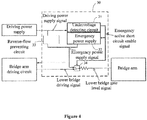
- the undervoltage detecting circuit is further configured to output, in a case of outputting the emergency active short-circuit enable signal, an emergency pulse lockout signal to the bridge arm driving circuit, to disenable the bridge arm driving circuit from outputting any bridge arm driving signal to the gate level selecting switch.
- the undervoltage detecting circuit outputs the emergency pulse lockout signal to the bridge arm driving circuit, to lockout an upper bridge driving signal and a lower bridge driving signal.
- the emergency pulse lockout signal may be generated by a comparator, which is not described in detail herein.
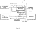
- the reverse-flow preventing circuit may include a reverse-flow preventing diode D1. As shown in Figure 5 , an anode of the reverse-flow preventing diode is connected to the driving power supply, and a cathode of the reverse-flow preventing diode is connected to the emergency power supply. Further, the reverse-flow preventing circuit may be any circuit that has a reverse-flow preventing function, which is not described in detail herein.
- the undervoltage detecting circuit may detect any one phase of driving power supply signals. As shown in Figure 6 , the undervoltage detecting circuit is configured to detect three phases of driving power supply signals. Hereinafter, the undervoltage detecting circuit is described by taking a U-phase driving power supply signal as an example.
- the undervoltage detecting circuit includes a stabilivolt D, a first resistor R1, a first transistor I1, a second resistor R2, a second transistor 12, and a third resistor R3, which are connected as follows.
- a cathode of the stabilivolt is connected to both a first terminal of the second resistor and a first terminal of the third resistor, and serves as an input terminal of the undervoltage detecting circuit.
- An anode of the stabilivolt is connected to both a first terminal of the first resistor and a control terminal of the first transistor.
- a second terminal of the first resistor, an output terminal of the first transistor, and an output terminal of the second transistor are grounded.
- An input terminal of the first transistor is connected to both a second terminal of the second resistor and a control terminal of the second transistor.
- An input terminal of the second transistor is connected to a second terminal of the third resistor, and serves as an output terminal of the undervoltage detecting circuit.
- the driving power supply signal is supplied to a cathode of the stabilivolt D.
- An anode of the stabilivolt is grounded via the first resistor R1 to form one branch, and the anode of the stabilivolt is further connected to a gate (that is, a control terminal) of the first transistor I1 to form another branch.
- a drain of the first transistor I1 is pulled up to the emergency power supply signal through the second resistor R2 to form one branch, and the drain of the first transistor I1 is further connected to a gate of the second transistor 12 to form another branch.
- An emergency active short-circuit enable signal is generated at a drain of the second transistor 12.
- the emergency active short-circuit enable signal is at a low level, it is indicated that the driving power supply is under voltage, the emergency power supply is enabled and the gate level selecting switch is controlled to turn on a second conduction path.
- the emergency active short-circuit enable signal is at a high level, it is indicated that the driving power supply is not under voltage, the emergency power supply is in a disenabled state.
- the emergency active short-circuit enable signal is pulled up to have the same level as the emergency power supply signal through the third resistor R3.
- the stabilivolt D is turned on.
- a voltage at the gate of the first transistor I1 is at a high level, such that the first transistor I1 is turned on.
- a voltage at the gate of the second transistor 12 is at a low level, such that the second transistor 12 is turned off, thus the emergency active short-circuit enable signal is at a high level.
- the stabilivolt D is turned off.
- the voltage at the gate of the first transistor I1 is at a low level, such that the first transistor I1 is turned off.
- the voltage at the gate of the second transistor 12 is at a high level, such that the second transistor 12 is turned on, thus the emergency active short-circuit enable signal is at a low level.
- V TH V Z + V Gth .
- emergency active short-circuit enable signals outputted from the three phases of branches may be all inputted to one branch in a logical relationship of "AND". That is, in a case that the driving power supply is under voltage at any one phase, the emergency active short-circuit enable signal is outputted to enable the emergency power supply.
- a logic device may be arranged to form a logical relationship of "OR" among the emergency active short-circuit enable signals as needed. That is, the emergency active short-circuit enable signal is outputted only in a case that all of the three phases of bridge arms are under voltage.
- the emergency power supply may be a linear power supply or a flyback power supply, for example, a direct current-to-direct current (DC-DC) converter having an enable port.
- An input terminal of the emergency power supply is connected to an external direct current side capacitor or another energy storage device.
- the emergency active short-circuit enable signal is transmitted to an enable port of the emergency power supply, to enable or disenable the emergency power supply.
- the gate level selecting switch is controlled to turn on the first conduction path.
- the bridge arm is connected to an output terminal of the bridge arm driving circuit.
- a level of a bridge arm gate level signal is determined based on the bridge arm driving circuit.
- the gate level selecting switch is controlled to turn on the second conduction path.
- the bridge arm is connected to the emergency power supply.
- the bridge arm gate level signal is pulled-up by the driving power supply. The upper bridge arms or the lower bridge arms are turned on, to realize the active short-circuit.
- a motor controller is further provided according to an embodiment of the present disclosure.
- the motor controller includes a low-voltage power supply, a driving power supply, a control circuit, a bridge arm driving circuit, a direct current side capacitor, a bridge arm and the circuit for actively performing short-circuit described above.
- the low-voltage power supply is connected to both the driving power supply and the control circuit, to supply power to the control circuit.
- the bridge arm driving circuit is connected to both the driving power supply and the control circuit. In a case that an amplitude of a driving power supply signal outputted from the driving power supply is higher than a first threshold, the bridge arm driving circuit is configured to output a bridge arm driving signal in response to a bridge arm driving control signal outputted from the control circuit. The bridge arm driving signal is transmitted to the bridge arm via the first conduction path. In a case that the amplitude of the driving power supply signal outputted from the driving power supply is lower than the first threshold, the circuit for actively performing short-circuit is configured to transmit an emergency power supply signal outputted from the emergency power supply to the bridge arm via the second conduction path.
- the undervoltage detecting circuit is further configured to output, in a case of outputting the emergency active short-circuit enable signal, an emergency pulse lockout signal to the bridge arm driving circuit, to disenable the bridge arm driving circuit from outputting any bridge arm driving signal.
- the gate level selecting switch is controlled to turn on the first conduction path in a case that the emergency active short-circuit enable signal is at a high level, and the gate level selecting switch is controlled to turn on the second conduction path in a case that the emergency active short-circuit enable signal is at a low level.
- a circuit for actively performing short-circuit which includes an undervoltage detecting circuit, an emergency power supply, a reverse-flow preventing circuit, and a gate level selecting switch.
- the undervoltage detecting circuit is configured to detect a driving power supply signal outputted from the driving power supply and output, in a case that the amplitude of the driving power supply signal is lower than a first threshold, an emergency active short-circuit enable signal.
- the emergency power supply is enabled and the gate level selecting switch is controlled to switch from a first conduction path to a second conduction path, to transmit an emergency power supply signal outputted from the emergency power supply to a bridge arm via the second conduction path. That is, in a case there is a fault in the driving power supply, the emergency power supply may be used to supply power to the bridge arm, thereby ensuring a normal drive of the bridge arm, thus ensuring the security of a vehicle.
- a reverse-flow preventing circuit is further arranged between the driving power supply and the emergency power supply, thereby preventing erroneous detection of the undervoltage detecting circuit on the driving power supply signal which is pulled-up by the emergency power supply signal in a case that the emergency power supply is enabled.
- units described in combination with the disclosed embodiments may be implemented by electronic hardware, computer software or a combination thereof.
- the units is generally described above based on functions. Whether the functions are realized by the hardware or the software is determined by specific applications of the technical solutions and design constraints. For each of the specific applications, those skilled in the art may adopt a specific implementation to realize the functions described above, and the implementation should fall within the scope of the present disclosure.
- ROM random-access memory
- ROM read-only memory
- EPROM electrically programmable random-access memory
- EEPROM electrically erasable programmable read-only memory
- register a hard disk, a removable disk, a compact disc read-only memory (CD-ROM), or any one of other storage media that are known in this technical field.
Landscapes
- Engineering & Computer Science (AREA)
- Power Engineering (AREA)
- Transportation (AREA)
- Mechanical Engineering (AREA)
- Life Sciences & Earth Sciences (AREA)
- Sustainable Development (AREA)
- Sustainable Energy (AREA)
- Business, Economics & Management (AREA)
- Emergency Management (AREA)
- Inverter Devices (AREA)
- Emergency Protection Circuit Devices (AREA)
Abstract
Description
- The present disclosure relates to the technical field of security protection of motor controllers, and in particular to a circuit for actively performing short-circuit and a motor controller.
- Motor controllers are widely used in the field of electric vehicles and the like. As shown in
Figure 1 , a motor controller mainly functions to convert a direct current voltage supplied from a high-voltage battery into a three-phase alternating current voltage required by a motor, and drive the motor under the control of a micro-controller, to provide a drive force or a braking torque to the vehicle. - Generally, the motor controller operates in an actively short-circuiting state for security. That is, the motor is controlled to have an output torque of approximate zero by the micro-controller, such that no uncontrollable acceleration or deceleration of the vehicle is caused. Specifically, the motor controller performs control to simultaneously turn on three phases of lower bridge arms or three phases of upper bridge arms, to cause a three-phase stator winding of the motor to be short-circuited, thereby realizing the active short-circuit. In a case that the motor is actively short-circuited under the control of the motor controller, a current may be generated in the winding of the motor due to an induced electromotive force generated when the motor rotates, which flows through the turned on three phases of lower bridge arms (or the three phases of upper bridge arms). Since there is no electrical energy exchanged between the motor and the high-voltage battery as well as between the motor and a direct current side capacitor, only a small braking torque is generated in the motor, thereby ensuring operating security of the vehicle.
- Reference is made to
Figure 2 , which is a schematic structural diagram of a system for actively performing short-circuit in the conventional technology. In the system for actively performing short-circuit, a control circuit controls a three-phase lower bridge driving module, to realize a security state. However, in the system for actively performing short-circuit, a low-voltage power supply is required to supply power to the control circuit and a driving power supply. The control circuit and the driving power supply cannot operate once there is a fault (for example, a power loss) in the low-voltage power supply, thus the three phases of lower bridge arms and the three phases of upper bridge arms are all turned off, thus failing to ensure security. - Therefore, a technical problem to be solved urgently by those skilled in the art is how to provide a circuit for actively performing short-circuit and a motor controller, to improve the security of the motor controller.
- In view of this, a circuit for actively performing short-circuit and a motor controller including the same are provided according to the embodiments of the present discourse, to improve the security of a motor controller.
- The circuit for actively performing short-circuit includes an undervoltage detecting circuit, an emergency power supply, a reverse-flow preventing circuit, and a gate level selecting switch. The undervoltage detecting circuit is connected to an external driving power supply, and is configured to detect a driving power supply signal outputted from the driving power supply and output, in a case that an amplitude of the driving power supply signal is lower than a first threshold, an emergency active short-circuit enable signal. The emergency power supply and the gate level selecting switch are connected to the undervoltage detecting circuit. In response to the emergency active short-circuit enable signal, the emergency power supply is enabled and the gate level selecting switch is controlled to switch from a first conduction path to a second conduction path, to transmit an emergency power supply signal outputted from the emergency power supply to a bridge arm via the second conduction path. The first conduction path is a path between the bridge arm and an external bridge arm driving circuit, and the second conduction path is a path between the bridge arm and the emergency power supply. The reverse-flow preventing circuit is arranged between the driving power supply and the emergency power supply, and is configured to insulate the driving power supply signal from the emergency power supply signal in a case that the emergency power supply is enabled.
- In an embodiment, the undervoltage detecting circuit includes a stabilivolt, a first resistor, a first transistor, a second resistor, a second transistor, and a third resistor. A cathode of the stabilivolt is connected to both a first terminal of the second resistor and a first terminal of the third resistor, and serves as an input terminal of the undervoltage detecting circuit. An anode of the stabilivolt is connected to both a first terminal of the first resistor and a control terminal of the first transistor. A second terminal of the first resistor, an output terminal of the first transistor, and an output terminal of the second transistor are grounded. An input terminal of the first transistor is connected to both a second terminal of the second resistor and a control terminal of the second transistor. An input terminal of the second transistor is connected to a second terminal of the third resistor, and serves as an output terminal of the undervoltage detecting circuit.
- In an embodiment, the emergency power supply is a direct current-to-direct current (DC-DC) converter having an enable port, and an input terminal of the emergency power supply is connected to an external direct current side capacitor.
- In an embodiment, the undervoltage detecting circuit is further configured to output, in a case of outputting the emergency active short-circuit enable signal, an emergency pulse lockout signal to the bridge arm driving circuit, to disenable the bridge arm driving circuit from outputting any bridge arm driving signal to the gate level selecting switch.
- In an embodiment, the reverse-flow preventing circuit includes a reverse-flow preventing diode. An anode of the reverse-flow preventing diode is connected to the driving power supply. A cathode of the reverse-flow preventing diode is connected to the emergency power supply.
- In an embodiment, each of the first transistor and the second transistor is turned on in response to a signal at a high level.
- In an embodiment, in a case that the emergency active short-circuit enable signal is at a high level, the gate level selecting switch is controlled to turn on the first conduction path. In a case that the emergency active short-circuit enable signal is at a low level, the gate level selecting switch is controlled to turn on the second conduction path.
- The motor controller includes a low-voltage power supply, a driving power supply, a control circuit, a bridge arm driving circuit, a direct current side capacitor, a bridge arm and the circuit for actively performing short-circuit described above. The low-voltage power supply is connected to both the driving power supply and the control circuit, and is configured to supply power to the control circuit. The bridge arm driving circuit is connected to both the driving power supply and the control circuit, and is configured to output, in a case that an amplitude of a driving power supply signal outputted from the driving power supply is higher than a first threshold, a bridge arm driving signal in response to a bridge arm driving control signal outputted from the control circuit. The bridge arm driving signal is transmitted to the bridge arm via the first conduction path. The circuit for actively performing short-circuit is configured to transmit, in a case that the amplitude of the driving power supply signal outputted from the driving power supply is lower than the first threshold, an emergency power supply signal outputted from the emergency power supply to the bridge arm via the second conduction path.
- In an embodiment, the undervoltage detecting circuit is further configured to output, in a case of outputting the emergency active short-circuit enable signal, an emergency pulse lockout signal to the bridge arm driving circuit, to disenable the bridge arm driving circuit from outputting any bridge arm driving signal.
- In an embodiment, in a case that the emergency active short-circuit enable signal is at a high level, the gate level selecting switch is controlled to turn on the first conduction path. In a case that emergency active short-circuit enable signal is at a low level, the gate level selecting switch is controlled to turn on the second conduction path.
- Based on the above technical solutions, a circuit for actively performing short-circuit is provided according to the present disclosure, which includes an undervoltage detecting circuit, an emergency power supply, a reverse-flow preventing circuit, and a gate level selecting switch. The undervoltage detecting circuit is configured to detect a driving power supply signal outputted from the driving power supply and output, in a case that an amplitude of the driving power supply signal is lower than a first threshold, an emergency active short-circuit enable signal. In response to the emergency active short-circuit enable signal, the emergency power supply is enabled and the gate level selecting switch is controlled to switch from a first conduction path to a second conduction path, to transmit an emergency power supply signal outputted from the emergency power supply to a bridge arm via the second conduction path. That is, in a case there is a fault in the driving power supply, the emergency power supply may be used to supply power to the bridge arm, thereby ensuring a normal drive of the bridge arm, thus ensuring the security of a vehicle.
- In addition, in the circuit for actively performing short-circuit, a reverse-flow preventing circuit is further arranged between the driving power supply and the emergency power supply, thereby preventing erroneous detection of the undervoltage detecting circuit on the driving power supply signal which is pulled-up by the emergency power supply signal in a case that the emergency power supply is enabled.
- In order to more clearly illustrate technical solutions in embodiments of the present disclosure or in the conventional technology, the drawings to be used in the description of the embodiments or the conventional technology are briefly described below. Apparently, the drawings in the following description show only embodiments of the present disclosure, and other drawings may be obtained by those skilled in the art from the drawings without making any creative work.
-
Figure 1 is a schematic structural diagram showing a circuit for actively performing short-circuit in the conventional technology; -
Figure 2 is a schematic structural block diagram showing a motor controller in the conventional technology; -
Figure 3 is a schematic structural diagram showing a circuit for actively performing short-circuit according to an embodiment of the present disclosure; -
Figure 4 is a schematic structural diagram showing a circuit for actively performing short-circuit according to another embodiment of the present disclosure; -
Figure 5 is a schematic structural diagram showing a circuit for actively performing short-circuit according to another embodiment of the present disclosure; -
Figure 6 is a schematic structural diagram showing a undervoltage detecting circuit in a circuit for actively performing short-circuit according to an embodiment of the present disclosure; and -
Figure 7 is a schematic structural block diagram showing a motor controller according to an embodiment of the present disclosure. - Referring to
Figure 2 , in the system for actively performing short-circuit, a low-voltage power supply is required to supply power to the control circuit and a driving power supply. The control circuit and the driving power supply cannot operate once there is a fault (for example, a power loss) in the low-voltage power supply, thus the three phases of lower bridge arms and the three phases of upper bridge arms are all turned off, thereby failing to ensure security. - Based on the above, reference is made to
Figure 3 , which is a schematic structural diagram showing a circuit for actively performing short-circuit according to an embodiment of the present disclosure. In a case there is a fault in a low-voltage power supply, an emergency power supply may be used to supply power to a bridge arm driving circuit, thereby improving the security of a motor controller. - Specifically, a circuit for actively performing short-
circuit 30 includes anundervoltage detecting circuit 31, anemergency power supply 32, a reverse-flow preventing circuit 33 and a gatelevel selecting switch 34. - The
undervoltage detecting circuit 31 is connected to an external driving power supply, and is configured to detect a driving power supply signal outputted from the driving power supply and output, in a case that an amplitude of the driving power supply signal is lower than a first threshold, an emergency active short-circuit enable signal. - The
emergency power supply 32 and the gatelevel selecting switch 34 are connected to theundervoltage detecting circuit 31. In response to the emergency active short-circuit enable signal, theemergency power supply 32 is enabled and the gatelevel selecting switch 34 is controlled to switch from a first conduction path to a second conduction path, to transmit an emergency power supply signal outputted from theemergency power supply 32 to a bridge arm via the second conduction path. The first conduction path is a path between the bridge arm and an external bridge arm driving circuit, and the second conduction path is a path between the bridge arm and theemergency power supply 32. - The reverse-
flow preventing circuit 33 is arranged between the driving power supply and theemergency power supply 32, and is configured to insulate the driving power supply signal from the emergency power supply signal in a case that theemergency power supply 32 is enabled. - It can be seen from the above that, in this embodiment, in a case that a power failure occurs in the driving power supply due to a fault in a low-voltage power supply (for example, a power loss in the low-voltage power supply) or a fault in the driving power supply of a vehicle, the undervoltage detecting circuit detects that the driving power supply signal is at a low level, the undervoltage detecting circuit outputs an emergency active short-circuit enable signal in a case of determining that an amplitude of the driving power supply signal is lower than the first threshold, to enable the emergency power supply and control the gate level selecting switch to switch to another state, such that the emergency power supply is connected to the bridge arm. In this way, a lower bridge gate level signal changes following the emergency power supply signal, to control an upper bridge arm or a lower bridge arm to be turned on, thereby realizing the active short-circuit, thus ensuring the security of a vehicle.
- It is to be noted that in this embodiment, the driving power supply may output one or more phases of driving power supply signals. For example, in a case that the bridge arm has a three-phase structure, the driving power supply may output three phases of driving power supply signals. The undervoltage detecting circuit is configured to detect each phase of the three phases of driving power supply signals, and output the emergency active short-circuit enable signal in a case of detecting that an amplitude of any one phase of the three phases of three-phase driving power supply signals is lower than the first threshold. Alternatively, the undervoltage detecting circuit is configured to output the emergency active short-circuit enable signal in a case of detecting that an amplitude of each phase of the three phases of driving power supply signals is lower than the first threshold.
- In addition, in the circuit for actively performing short-circuit, a reverse-flow preventing circuit is further arranged between the driving power supply and the emergency power supply, thereby preventing erroneous detection of the undervoltage detecting circuit on the driving power supply signal which is pulled-up by the emergency power supply signal in a case that the emergency power supply is enabled.
- Based on the above embodiment, in a circuit for actively performing short-circuit according to an embodiment of the present disclosure, as shown in
Figure 4 , the undervoltage detecting circuit is further configured to output, in a case of outputting the emergency active short-circuit enable signal, an emergency pulse lockout signal to the bridge arm driving circuit, to disenable the bridge arm driving circuit from outputting any bridge arm driving signal to the gate level selecting switch. - Specifically, in a case that the amplitude of the driving power supply signal is lower than the first threshold, the undervoltage detecting circuit outputs the emergency pulse lockout signal to the bridge arm driving circuit, to lockout an upper bridge driving signal and a lower bridge driving signal. The emergency pulse lockout signal may be generated by a comparator, which is not described in detail herein.
- In addition, in this embodiment, the reverse-flow preventing circuit may include a reverse-flow preventing diode D1. As shown in
Figure 5 , an anode of the reverse-flow preventing diode is connected to the driving power supply, and a cathode of the reverse-flow preventing diode is connected to the emergency power supply. Further, the reverse-flow preventing circuit may be any circuit that has a reverse-flow preventing function, which is not described in detail herein. - Further, a specific structure of an undervoltage detecting circuit is provided according to an embodiment of the present disclosure. The undervoltage detecting circuit may detect any one phase of driving power supply signals. As shown in
Figure 6 , the undervoltage detecting circuit is configured to detect three phases of driving power supply signals. Hereinafter, the undervoltage detecting circuit is described by taking a U-phase driving power supply signal as an example. The undervoltage detecting circuit includes a stabilivolt D, a first resistor R1, a first transistor I1, a second resistor R2, asecond transistor 12, and a third resistor R3, which are connected as follows. - A cathode of the stabilivolt is connected to both a first terminal of the second resistor and a first terminal of the third resistor, and serves as an input terminal of the undervoltage detecting circuit. An anode of the stabilivolt is connected to both a first terminal of the first resistor and a control terminal of the first transistor. A second terminal of the first resistor, an output terminal of the first transistor, and an output terminal of the second transistor are grounded. An input terminal of the first transistor is connected to both a second terminal of the second resistor and a control terminal of the second transistor. An input terminal of the second transistor is connected to a second terminal of the third resistor, and serves as an output terminal of the undervoltage detecting circuit.
- With reference to the schematic structural diagram shown in
Figure 6 , an operation principle of the undervoltage detecting circuit is described as follows. - The driving power supply signal is supplied to a cathode of the stabilivolt D. An anode of the stabilivolt is grounded via the first resistor R1 to form one branch, and the anode of the stabilivolt is further connected to a gate (that is, a control terminal) of the first transistor I1 to form another branch. A drain of the first transistor I1 is pulled up to the emergency power supply signal through the second resistor R2 to form one branch, and the drain of the first transistor I1 is further connected to a gate of the
second transistor 12 to form another branch. An emergency active short-circuit enable signal is generated at a drain of thesecond transistor 12. In a case that the emergency active short-circuit enable signal is at a low level, it is indicated that the driving power supply is under voltage, the emergency power supply is enabled and the gate level selecting switch is controlled to turn on a second conduction path. In a case that the emergency active short-circuit enable signal is at a high level, it is indicated that the driving power supply is not under voltage, the emergency power supply is in a disenabled state. - The emergency active short-circuit enable signal is pulled up to have the same level as the emergency power supply signal through the third resistor R3. In a case that the driving power supply signal is higher than a breakdown voltage of the stabilivolt D, the stabilivolt D is turned on. In this case, a voltage at the gate of the first transistor I1 is at a high level, such that the first transistor I1 is turned on. A voltage at the gate of the
second transistor 12 is at a low level, such that thesecond transistor 12 is turned off, thus the emergency active short-circuit enable signal is at a high level. - In a case that the driving power supply signal is lower than the breakdown voltage of the stabilivolt D, the stabilivolt D is turned off. The voltage at the gate of the first transistor I1 is at a low level, such that the first transistor I1 is turned off. The voltage at the gate of the
second transistor 12 is at a high level, such that thesecond transistor 12 is turned on, thus the emergency active short-circuit enable signal is at a low level. - It is assumed that the breakdown voltage of the stabilivolt D is denoted by Vz , and a conduction threshold of the first transistor I1 is denoted by VGth , an operation voltage (that is, a threshold VTH of the undervoltage detecting circuit) of the first transistor I1 may be expressed by: VTH = VZ + VGth.
- In addition, operation principle of the undervoltage detecting circuit for the V-phase driving power supply signal and the W-phase driving power supply signal is the same as that for the U-phase driving power supply signal. Emergency active short-circuit enable signals outputted from the three phases of branches may be all inputted to one branch in a logical relationship of "AND". That is, in a case that the driving power supply is under voltage at any one phase, the emergency active short-circuit enable signal is outputted to enable the emergency power supply. Alternatively, a logic device may be arranged to form a logical relationship of "OR" among the emergency active short-circuit enable signals as needed. That is, the emergency active short-circuit enable signal is outputted only in a case that all of the three phases of bridge arms are under voltage.
- Based on the above embodiments, a specific implementation of the emergency power supply and a specific implementation of the gate level selecting switch are further provided. The emergency power supply may be a linear power supply or a flyback power supply, for example, a direct current-to-direct current (DC-DC) converter having an enable port. An input terminal of the emergency power supply is connected to an external direct current side capacitor or another energy storage device. The emergency active short-circuit enable signal is transmitted to an enable port of the emergency power supply, to enable or disenable the emergency power supply.
- In a case that the emergency active short-circuit enable signal is at a high level, the gate level selecting switch is controlled to turn on the first conduction path. In this case, the bridge arm is connected to an output terminal of the bridge arm driving circuit. A level of a bridge arm gate level signal is determined based on the bridge arm driving circuit. In a case that the emergency active short-circuit enable signal is at a low level, the gate level selecting switch is controlled to turn on the second conduction path. In this case, the bridge arm is connected to the emergency power supply. The bridge arm gate level signal is pulled-up by the driving power supply. The upper bridge arms or the lower bridge arms are turned on, to realize the active short-circuit.
- Based on the above embodiments, a motor controller is further provided according to an embodiment of the present disclosure. As shown in
Figure 7 , the motor controller includes a low-voltage power supply, a driving power supply, a control circuit, a bridge arm driving circuit, a direct current side capacitor, a bridge arm and the circuit for actively performing short-circuit described above. - The low-voltage power supply is connected to both the driving power supply and the control circuit, to supply power to the control circuit. The bridge arm driving circuit is connected to both the driving power supply and the control circuit. In a case that an amplitude of a driving power supply signal outputted from the driving power supply is higher than a first threshold, the bridge arm driving circuit is configured to output a bridge arm driving signal in response to a bridge arm driving control signal outputted from the control circuit. The bridge arm driving signal is transmitted to the bridge arm via the first conduction path. In a case that the amplitude of the driving power supply signal outputted from the driving power supply is lower than the first threshold, the circuit for actively performing short-circuit is configured to transmit an emergency power supply signal outputted from the emergency power supply to the bridge arm via the second conduction path.
- For an operation principle of the motor controller, reference may be made to the operation principle of the circuit for actively performing short-circuit described above.
- Based on the above embodiments, in the motor controller according to this embodiment, the undervoltage detecting circuit is further configured to output, in a case of outputting the emergency active short-circuit enable signal, an emergency pulse lockout signal to the bridge arm driving circuit, to disenable the bridge arm driving circuit from outputting any bridge arm driving signal.
- In addition, with the motor controller in this embodiment, the gate level selecting switch is controlled to turn on the first conduction path in a case that the emergency active short-circuit enable signal is at a high level, and the gate level selecting switch is controlled to turn on the second conduction path in a case that the emergency active short-circuit enable signal is at a low level.
- In summary, a circuit for actively performing short-circuit is provided according to the present disclosure, which includes an undervoltage detecting circuit, an emergency power supply, a reverse-flow preventing circuit, and a gate level selecting switch. The undervoltage detecting circuit is configured to detect a driving power supply signal outputted from the driving power supply and output, in a case that the amplitude of the driving power supply signal is lower than a first threshold, an emergency active short-circuit enable signal. In response to the emergency active short-circuit enable signal, the emergency power supply is enabled and the gate level selecting switch is controlled to switch from a first conduction path to a second conduction path, to transmit an emergency power supply signal outputted from the emergency power supply to a bridge arm via the second conduction path. That is, in a case there is a fault in the driving power supply, the emergency power supply may be used to supply power to the bridge arm, thereby ensuring a normal drive of the bridge arm, thus ensuring the security of a vehicle.
- In addition, in the circuit for actively performing short-circuit, a reverse-flow preventing circuit is further arranged between the driving power supply and the emergency power supply, thereby preventing erroneous detection of the undervoltage detecting circuit on the driving power supply signal which is pulled-up by the emergency power supply signal in a case that the emergency power supply is enabled.
- The embodiments in this specification are described in a progressive way, each of which emphasizes the differences from others, and the same or similar parts among the embodiments may be referred to each other. Since the motor controller disclosed in the embodiments corresponds to the disclosed circuit for actively performing short-circuit, the description thereof is relatively simple, and for relevant parts, references may be made to the description of the circuit for actively performing short-circuit.
- It is to be further understood by those skilled in the art that units described in combination with the disclosed embodiments may be implemented by electronic hardware, computer software or a combination thereof. In order to clearly describe interchangeability of the hardware and the software, the units is generally described above based on functions. Whether the functions are realized by the hardware or the software is determined by specific applications of the technical solutions and design constraints. For each of the specific applications, those skilled in the art may adopt a specific implementation to realize the functions described above, and the implementation should fall within the scope of the present disclosure.
- Functions of units described in combination with the disclosed embodiments may be directly performed by hardware, software modules that are executed by a processor, or a combination thereof. The software modules may be arranged in a random-access memory (ROM), an internal memory, a read-only memory (ROM), an electrically programmable random-access memory (EPROM), an electrically erasable programmable read-only memory (EEPROM), a register, a hard disk, a removable disk, a compact disc read-only memory (CD-ROM), or any one of other storage media that are known in this technical field.
- With the description of the embodiments disclosed above, those skilled in the art may implement or use technical solutions of the present disclosure. Numerous modifications to the embodiments are apparent to those skilled in the art, and the general principles defined herein may be implemented in other embodiments.
Claims (10)
- A circuit for actively performing short-circuit, comprising:an undervoltage detecting circuit, wherein the undervoltage detecting circuit is connected to an external driving power supply, and is configured to detect a driving power supply signal outputted from the external driving power supply and output, in a case that an amplitude of the driving power supply signal is lower than a first threshold, an emergency active short-circuit enable signal;an emergency power supply and an gate level selecting switch which are connected to the undervoltage detecting circuit, wherein in response to the emergency active short-circuit enable signal, the emergency power supply is enabled and the gate level selecting switch is controlled to switch from a first conduction path to a second conduction path, to transmit an emergency power supply signal outputted from the emergency power supply to a bridge arm via the second conduction path, and wherein the first conduction path is a path between the bridge arm and an external bridge arm driving circuit, and the second conduction path is a path between the bridge arm and the emergency power supply; anda reverse-flow preventing circuit, wherein the reverse-flow preventing circuit is arranged between the external driving power supply and the emergency power supply, and is configured to insulate the driving power supply signal from the emergency power supply signal in a case that the emergency power supply is enabled.
- The circuit for actively performing short-circuit according to claim 1, wherein the undervoltage detecting circuit comprises a stabilivolt, a first resistor, a first transistor, a second resistor, a second transistor, and a third resistor, and wherein
a cathode of the stabilivolt is connected to both a first terminal of the second resistor and a first terminal of the third resistor, and serves as an input terminal of the undervoltage detecting circuit;
an anode of the stabilivolt is connected to both a first terminal of the first resistor and a control terminal of the first transistor;
a second terminal of the first resistor, an output terminal of the first transistor, and an output terminal of the second transistor are grounded;
an input terminal of the first transistor is connected to both a second terminal of the second resistor and a control terminal of the second transistor; and
an input terminal of the second transistor is connected to a second terminal of the third resistor, and serves as an output terminal of the undervoltage detecting circuit. - The circuit for actively performing short-circuit according to claim 1, wherein the emergency power supply is a direct current-to-direct current (DC-DC) converter having an enable port, and an input terminal of the emergency power supply is connected to an external direct current side capacitor.
- The circuit for actively performing short-circuit according to claim 1, wherein the undervoltage detecting circuit is further configured to output, in a case of outputting the emergency active short-circuit enable signal, an emergency pulse lockout signal to the external bridge arm driving circuit, to disenable the external bridge arm driving circuit from outputting any bridge arm driving signal to the gate level selecting switch.
- The circuit for actively performing short-circuit according to claim 1, wherein the reverse-flow preventing circuit comprises a reverse-flow preventing diode, an anode of the reverse-flow preventing diode is connected to the external driving power supply, and a cathode of the reverse-flow preventing diode is connected to the emergency power supply.
- The circuit for actively performing short-circuit according to claim 2, wherein each of the first transistor and the second transistor is turned on in response to a signal at a high level.
- The circuit for actively performing short-circuit according to claim 1, wherein
in a case that the emergency active short-circuit enable signal is at a high level, the gate level selecting switch is controlled to turn on the first conduction path; and
in a case that the emergency active short-circuit enable signal is at a low level, the gate level selecting switch is controlled to turn on the second conduction path. - A motor controller, comprising: a low-voltage power supply, a driving power supply, a control circuit, a bridge arm driving circuit, a direct current side capacitor, a bridge arm and the circuit for actively performing short-circuit according to any one of claims 1 to 7, wherein
the low-voltage power supply is connected to both the driving power supply and the control circuit, and is configured to supply power to the control circuit;
the bridge arm driving circuit is connected to both the driving power supply and the control circuit, and is configured to output, in a case that an amplitude of a driving power supply signal outputted from the driving power supply is higher than a first threshold, a bridge arm driving signal in response to a bridge arm driving control signal outputted from the control circuit, wherein the bridge arm driving signal is transmitted to the bridge arm via the first conduction path; and
the circuit for actively performing short-circuit is configured to transmit, in a case that the amplitude of the driving power supply signal outputted from the driving power supply is lower than the first threshold, an emergency power supply signal outputted from the emergency power supply to the bridge arm via the second conduction path. - The motor controller according to claim 8, wherein the undervoltage detecting circuit is further configured to output, in a case of outputting the emergency active short-circuit enable signal, an emergency pulse lockout signal to the bridge arm driving circuit, to disenable the bridge arm driving circuit from outputting any bridge arm driving signal.
- The motor controller according to claim 8, wherein
in a case that the emergency active short-circuit enable signal is at a high level, the gate level selecting switch is controlled to turn on the first conduction path; and
in a case that the emergency active short-circuit enable signal is at a low level, the gate level selecting switch is controlled to turn on the second conduction path.
Applications Claiming Priority (1)
| Application Number | Priority Date | Filing Date | Title |
|---|---|---|---|
| CN201810993191.4A CN109039221B (en) | 2018-08-29 | 2018-08-29 | Active short circuit and motor controller |
Publications (3)
| Publication Number | Publication Date |
|---|---|
| EP3618259A1 true EP3618259A1 (en) | 2020-03-04 |
| EP3618259B1 EP3618259B1 (en) | 2024-04-17 |
| EP3618259C0 EP3618259C0 (en) | 2024-04-17 |
Family
ID=64625827
Family Applications (1)
| Application Number | Title | Priority Date | Filing Date |
|---|---|---|---|
| EP19187781.0A Active EP3618259B1 (en) | 2018-08-29 | 2019-07-23 | Circuit for actively performing short-circuit and motor controller |
Country Status (3)
| Country | Link |
|---|---|
| US (1) | US11146204B2 (en) |
| EP (1) | EP3618259B1 (en) |
| CN (1) | CN109039221B (en) |
Cited By (1)
| Publication number | Priority date | Publication date | Assignee | Title |
|---|---|---|---|---|
| FR3132893A1 (en) * | 2022-02-22 | 2023-08-25 | Ez-Wheel | ENGINE CONTROL SYSTEM WITH ELECTRIC SAFETY BRAKING |
Families Citing this family (11)
| Publication number | Priority date | Publication date | Assignee | Title |
|---|---|---|---|---|
| FR3091052B1 (en) * | 2018-12-20 | 2021-05-21 | Valeo Equip Electr Moteur | Voltage converter control system |
| CN111769780B (en) * | 2019-03-29 | 2022-02-08 | 北京新能源汽车股份有限公司 | Control method and device of motor controller and automobile |
| CN111641330B (en) * | 2020-06-29 | 2025-02-28 | 上海英恒电子有限公司 | A driving circuit and a motor controller |
| CN111900897B (en) * | 2020-07-03 | 2022-02-22 | 广东博智林机器人有限公司 | Band-type brake circuit, servo driver and detection method of band-type brake circuit |
| CN111817257B (en) * | 2020-07-28 | 2025-08-29 | 苏州汇川联合动力系统股份有限公司 | Low voltage power supply power-off protection circuit and low voltage power supply power-off protection device |
| CN112532116B (en) * | 2020-12-09 | 2024-07-19 | 金华市科欣医疗科技有限公司 | Control circuit of motor electromagnetic brake |
| CN113479065B (en) * | 2021-07-29 | 2023-01-10 | 中国第一汽车股份有限公司 | Motor active short circuit control circuit and driving method thereof |
| CN113922492B (en) * | 2021-10-12 | 2025-04-22 | 臻驱科技(上海)股份有限公司 | Internal power supply structure of motor controller, electric vehicle and power supply method |
| CN115278976A (en) * | 2022-08-16 | 2022-11-01 | 台州市椒江萤星电子电器有限公司 | Series structure of cascaded point-controlled LED lamp string and series-parallel structure thereof |
| US12126163B2 (en) | 2022-12-16 | 2024-10-22 | Bae Systems Controls Inc. | Protection system and protection method for power converters |
| CN116061705B (en) * | 2023-01-19 | 2025-11-04 | 北京新能源汽车股份有限公司 | A control circuit for an electric vehicle and its drive motor |
Citations (2)
| Publication number | Priority date | Publication date | Assignee | Title |
|---|---|---|---|---|
| US20160094024A1 (en) * | 2014-09-25 | 2016-03-31 | Power Mate Technology Co., Ltd. | Under voltage protection device |
| JP2017118815A (en) * | 2015-12-17 | 2017-06-29 | アイシン・エィ・ダブリュ株式会社 | Inverter control circuit |
Family Cites Families (13)
| Publication number | Priority date | Publication date | Assignee | Title |
|---|---|---|---|---|
| JP2001119960A (en) * | 1999-10-21 | 2001-04-27 | Auto Network Gijutsu Kenkyusho:Kk | Emergency shut-off method and device for vehicle power supply circuit and voltage converter for vehicle |
| JP3505124B2 (en) * | 2000-03-28 | 2004-03-08 | 東京電力株式会社 | Emergency power supply system and system for automatically detecting the presence or absence of failure of a single cell in a battery used in the system |
| CN1193483C (en) * | 2002-04-18 | 2005-03-16 | 艾默生网络能源有限公司 | Method and device for generating driving power supply |
| AU2003252451A1 (en) * | 2002-08-01 | 2004-02-23 | Japan Storage Battery Co., Ltd. | Vehicle power source device and vehicle using the power source device |
| US6801028B2 (en) * | 2002-11-14 | 2004-10-05 | Fyre Storm, Inc. | Phase locked looped based digital pulse converter |
| US7161331B2 (en) * | 2005-04-11 | 2007-01-09 | Yuan Ze University | Boost converter utilizing bi-directional magnetic energy transfer of coupling inductor |
| US8067859B2 (en) * | 2008-12-11 | 2011-11-29 | Infineon Technologies Ag | Reverse polarity protection for MOSFETs |
| CN102969918B (en) * | 2012-11-06 | 2016-03-02 | 联合汽车电子有限公司 | Three-phase bridge type converter system and promptly descend short-circuit protection circuit |
| WO2016104318A1 (en) * | 2014-12-25 | 2016-06-30 | アイシン・エィ・ダブリュ株式会社 | Rotating electric machine control device |
| CN204836744U (en) * | 2015-08-25 | 2015-12-02 | 阮树成 | Hand over human response filing cabinet of straight stand -by power supply LED lamp of adjusting luminance |
| CN105514941A (en) * | 2015-12-31 | 2016-04-20 | 联合汽车电子有限公司 | Electric vehicle inverter protective device and method |
| CN205945026U (en) * | 2016-08-05 | 2017-02-08 | 上海金脉电子科技有限公司 | Machine controller who possesses security function |
| CN107017816B (en) * | 2017-04-25 | 2019-06-04 | 南京航空航天大学 | Fault-tolerant electric vehicle drive and charging system and fault reconstruction method |
-
2018
- 2018-08-29 CN CN201810993191.4A patent/CN109039221B/en active Active
-
2019
- 2019-07-16 US US16/513,348 patent/US11146204B2/en active Active
- 2019-07-23 EP EP19187781.0A patent/EP3618259B1/en active Active
Patent Citations (2)
| Publication number | Priority date | Publication date | Assignee | Title |
|---|---|---|---|---|
| US20160094024A1 (en) * | 2014-09-25 | 2016-03-31 | Power Mate Technology Co., Ltd. | Under voltage protection device |
| JP2017118815A (en) * | 2015-12-17 | 2017-06-29 | アイシン・エィ・ダブリュ株式会社 | Inverter control circuit |
Cited By (3)
| Publication number | Priority date | Publication date | Assignee | Title |
|---|---|---|---|---|
| FR3132893A1 (en) * | 2022-02-22 | 2023-08-25 | Ez-Wheel | ENGINE CONTROL SYSTEM WITH ELECTRIC SAFETY BRAKING |
| WO2023161580A1 (en) | 2022-02-22 | 2023-08-31 | Ez-Wheel | Motor control system with electric safety braking |
| US12686284B2 (en) | 2022-02-22 | 2026-07-21 | Ez-Wheel | Motor control system with electric safety braking |
Also Published As
| Publication number | Publication date |
|---|---|
| US11146204B2 (en) | 2021-10-12 |
| EP3618259B1 (en) | 2024-04-17 |
| US20200076347A1 (en) | 2020-03-05 |
| EP3618259C0 (en) | 2024-04-17 |
| CN109039221B (en) | 2021-12-10 |
| CN109039221A (en) | 2018-12-18 |
Similar Documents
| Publication | Publication Date | Title |
|---|---|---|
| US11146204B2 (en) | Circuit for actively performing short-circuit and motor controller | |
| CN109159669B (en) | A protection system and method for an electric drive system | |
| JP6169203B1 (en) | Electric motor control apparatus and electric motor control method | |
| JP5315155B2 (en) | Semiconductor element control device, automotive electrical system | |
| US12009654B2 (en) | Motor control system and motor control device | |
| CN110829949A (en) | Electric drive system fault protection method and device, vehicle and storage medium | |
| JP3625692B2 (en) | Automotive power converter | |
| CN114189194B (en) | Motor control unit, motor unit and vehicle | |
| US11973368B2 (en) | Control apparatus of power converter | |
| CN111656666B (en) | power conversion device | |
| US12107571B2 (en) | Control circuit for power conversion apparatus | |
| JP2017118815A (en) | Inverter control circuit | |
| EP3010137B1 (en) | Multilevel inverter | |
| CN115593240A (en) | Motor Controllers and Electric Vehicles | |
| CN106575925A (en) | power conversion device | |
| US11894791B2 (en) | Control device, motor driving apparatus, and motor driving system | |
| US11012021B2 (en) | Inverter device and control circuit therefor, and motor driving system | |
| CN114421819A (en) | Vehicle-mounted inverter power supply circuit, vehicle-mounted inverter and vehicle | |
| JP2014165956A (en) | Rotary electric machine drive device | |
| WO2021161796A1 (en) | Control circuit for power converter | |
| US10498272B2 (en) | Control device of electric rotating machine | |
| JP2021065039A (en) | Switch drive device | |
| US20260142557A1 (en) | Power conversion device | |
| CN116960899A (en) | Motor drive control circuit, motor control module and automobile | |
| WO2022019038A1 (en) | Control circuit for power converter |
Legal Events
| Date | Code | Title | Description |
|---|---|---|---|
| PUAI | Public reference made under article 153(3) epc to a published international application that has entered the european phase |
Free format text: ORIGINAL CODE: 0009012 |
|
| STAA | Information on the status of an ep patent application or granted ep patent |
Free format text: STATUS: THE APPLICATION HAS BEEN PUBLISHED |
|
| AK | Designated contracting states |
Kind code of ref document: A1 Designated state(s): AL AT BE BG CH CY CZ DE DK EE ES FI FR GB GR HR HU IE IS IT LI LT LU LV MC MK MT NL NO PL PT RO RS SE SI SK SM TR |
|
| AX | Request for extension of the european patent |
Extension state: BA ME |
|
| STAA | Information on the status of an ep patent application or granted ep patent |
Free format text: STATUS: REQUEST FOR EXAMINATION WAS MADE |
|
| RIN1 | Information on inventor provided before grant (corrected) |
Inventor name: CHEN, WENJIE Inventor name: YU, ANBO |
|
| 17P | Request for examination filed |
Effective date: 20200904 |
|
| RBV | Designated contracting states (corrected) |
Designated state(s): AL AT BE BG CH CY CZ DE DK EE ES FI FR GB GR HR HU IE IS IT LI LT LU LV MC MK MT NL NO PL PT RO RS SE SI SK SM TR |
|
| STAA | Information on the status of an ep patent application or granted ep patent |
Free format text: STATUS: EXAMINATION IS IN PROGRESS |
|
| 17Q | First examination report despatched |
Effective date: 20211026 |
|
| GRAP | Despatch of communication of intention to grant a patent |
Free format text: ORIGINAL CODE: EPIDOSNIGR1 |
|
| STAA | Information on the status of an ep patent application or granted ep patent |
Free format text: STATUS: GRANT OF PATENT IS INTENDED |
|
| RIC1 | Information provided on ipc code assigned before grant |
Ipc: H02H 3/24 20060101ALN20231123BHEP Ipc: H03K 17/06 20060101ALN20231123BHEP Ipc: B60L 15/20 20060101ALI20231123BHEP Ipc: B60L 3/00 20190101ALI20231123BHEP Ipc: B60L 7/00 20060101ALI20231123BHEP Ipc: H02P 29/028 20160101ALI20231123BHEP Ipc: H02P 29/024 20160101ALI20231123BHEP Ipc: H02P 3/12 20060101ALI20231123BHEP Ipc: H02P 3/22 20060101AFI20231123BHEP |
|
| INTG | Intention to grant announced |
Effective date: 20231208 |
|
| GRAS | Grant fee paid |
Free format text: ORIGINAL CODE: EPIDOSNIGR3 |
|
| GRAA | (expected) grant |
Free format text: ORIGINAL CODE: 0009210 |
|
| STAA | Information on the status of an ep patent application or granted ep patent |
Free format text: STATUS: THE PATENT HAS BEEN GRANTED |
|
| AK | Designated contracting states |
Kind code of ref document: B1 Designated state(s): AL AT BE BG CH CY CZ DE DK EE ES FI FR GB GR HR HU IE IS IT LI LT LU LV MC MK MT NL NO PL PT RO RS SE SI SK SM TR |
|
| REG | Reference to a national code |
Ref country code: GB Ref legal event code: FG4D |
|
| REG | Reference to a national code |
Ref country code: CH Ref legal event code: EP |
|
| REG | Reference to a national code |
Ref country code: IE Ref legal event code: FG4D Ref country code: DE Ref legal event code: R096 Ref document number: 602019050332 Country of ref document: DE |
|
| U01 | Request for unitary effect filed |
Effective date: 20240429 |
|
| U07 | Unitary effect registered |
Designated state(s): AT BE BG DE DK EE FI FR IT LT LU LV MT NL PT SE SI Effective date: 20240506 |
|
| U20 | Renewal fee for the european patent with unitary effect paid |
Year of fee payment: 6 Effective date: 20240607 |
|
| PG25 | Lapsed in a contracting state [announced via postgrant information from national office to epo] |
Ref country code: IS Free format text: LAPSE BECAUSE OF FAILURE TO SUBMIT A TRANSLATION OF THE DESCRIPTION OR TO PAY THE FEE WITHIN THE PRESCRIBED TIME-LIMIT Effective date: 20240817 |
|
| PG25 | Lapsed in a contracting state [announced via postgrant information from national office to epo] |
Ref country code: HR Free format text: LAPSE BECAUSE OF FAILURE TO SUBMIT A TRANSLATION OF THE DESCRIPTION OR TO PAY THE FEE WITHIN THE PRESCRIBED TIME-LIMIT Effective date: 20240417 |
|
| PG25 | Lapsed in a contracting state [announced via postgrant information from national office to epo] |
Ref country code: GR Free format text: LAPSE BECAUSE OF FAILURE TO SUBMIT A TRANSLATION OF THE DESCRIPTION OR TO PAY THE FEE WITHIN THE PRESCRIBED TIME-LIMIT Effective date: 20240718 |
|
| PG25 | Lapsed in a contracting state [announced via postgrant information from national office to epo] |
Ref country code: ES Free format text: LAPSE BECAUSE OF FAILURE TO SUBMIT A TRANSLATION OF THE DESCRIPTION OR TO PAY THE FEE WITHIN THE PRESCRIBED TIME-LIMIT Effective date: 20240417 |
|
| PG25 | Lapsed in a contracting state [announced via postgrant information from national office to epo] |
Ref country code: PL Free format text: LAPSE BECAUSE OF FAILURE TO SUBMIT A TRANSLATION OF THE DESCRIPTION OR TO PAY THE FEE WITHIN THE PRESCRIBED TIME-LIMIT Effective date: 20240417 |
|
| PG25 | Lapsed in a contracting state [announced via postgrant information from national office to epo] |
Ref country code: PL Free format text: LAPSE BECAUSE OF FAILURE TO SUBMIT A TRANSLATION OF THE DESCRIPTION OR TO PAY THE FEE WITHIN THE PRESCRIBED TIME-LIMIT Effective date: 20240417 Ref country code: NO Free format text: LAPSE BECAUSE OF FAILURE TO SUBMIT A TRANSLATION OF THE DESCRIPTION OR TO PAY THE FEE WITHIN THE PRESCRIBED TIME-LIMIT Effective date: 20240717 Ref country code: IS Free format text: LAPSE BECAUSE OF FAILURE TO SUBMIT A TRANSLATION OF THE DESCRIPTION OR TO PAY THE FEE WITHIN THE PRESCRIBED TIME-LIMIT Effective date: 20240817 Ref country code: HR Free format text: LAPSE BECAUSE OF FAILURE TO SUBMIT A TRANSLATION OF THE DESCRIPTION OR TO PAY THE FEE WITHIN THE PRESCRIBED TIME-LIMIT Effective date: 20240417 Ref country code: GR Free format text: LAPSE BECAUSE OF FAILURE TO SUBMIT A TRANSLATION OF THE DESCRIPTION OR TO PAY THE FEE WITHIN THE PRESCRIBED TIME-LIMIT Effective date: 20240718 Ref country code: ES Free format text: LAPSE BECAUSE OF FAILURE TO SUBMIT A TRANSLATION OF THE DESCRIPTION OR TO PAY THE FEE WITHIN THE PRESCRIBED TIME-LIMIT Effective date: 20240417 Ref country code: RS Free format text: LAPSE BECAUSE OF FAILURE TO SUBMIT A TRANSLATION OF THE DESCRIPTION OR TO PAY THE FEE WITHIN THE PRESCRIBED TIME-LIMIT Effective date: 20240717 |
|
| REG | Reference to a national code |
Ref country code: DE Ref legal event code: R097 Ref document number: 602019050332 Country of ref document: DE |
|
| PG25 | Lapsed in a contracting state [announced via postgrant information from national office to epo] |
Ref country code: CZ Free format text: LAPSE BECAUSE OF FAILURE TO SUBMIT A TRANSLATION OF THE DESCRIPTION OR TO PAY THE FEE WITHIN THE PRESCRIBED TIME-LIMIT Effective date: 20240417 |
|
| PG25 | Lapsed in a contracting state [announced via postgrant information from national office to epo] |
Ref country code: RO Free format text: LAPSE BECAUSE OF FAILURE TO SUBMIT A TRANSLATION OF THE DESCRIPTION OR TO PAY THE FEE WITHIN THE PRESCRIBED TIME-LIMIT Effective date: 20240417 Ref country code: SK Free format text: LAPSE BECAUSE OF FAILURE TO SUBMIT A TRANSLATION OF THE DESCRIPTION OR TO PAY THE FEE WITHIN THE PRESCRIBED TIME-LIMIT Effective date: 20240417 |
|
| PG25 | Lapsed in a contracting state [announced via postgrant information from national office to epo] |
Ref country code: SM Free format text: LAPSE BECAUSE OF FAILURE TO SUBMIT A TRANSLATION OF THE DESCRIPTION OR TO PAY THE FEE WITHIN THE PRESCRIBED TIME-LIMIT Effective date: 20240417 |
|
| PG25 | Lapsed in a contracting state [announced via postgrant information from national office to epo] |
Ref country code: SM Free format text: LAPSE BECAUSE OF FAILURE TO SUBMIT A TRANSLATION OF THE DESCRIPTION OR TO PAY THE FEE WITHIN THE PRESCRIBED TIME-LIMIT Effective date: 20240417 Ref country code: SK Free format text: LAPSE BECAUSE OF FAILURE TO SUBMIT A TRANSLATION OF THE DESCRIPTION OR TO PAY THE FEE WITHIN THE PRESCRIBED TIME-LIMIT Effective date: 20240417 Ref country code: RO Free format text: LAPSE BECAUSE OF FAILURE TO SUBMIT A TRANSLATION OF THE DESCRIPTION OR TO PAY THE FEE WITHIN THE PRESCRIBED TIME-LIMIT Effective date: 20240417 Ref country code: CZ Free format text: LAPSE BECAUSE OF FAILURE TO SUBMIT A TRANSLATION OF THE DESCRIPTION OR TO PAY THE FEE WITHIN THE PRESCRIBED TIME-LIMIT Effective date: 20240417 |
|
| PG25 | Lapsed in a contracting state [announced via postgrant information from national office to epo] |
Ref country code: MC Free format text: LAPSE BECAUSE OF FAILURE TO SUBMIT A TRANSLATION OF THE DESCRIPTION OR TO PAY THE FEE WITHIN THE PRESCRIBED TIME-LIMIT Effective date: 20240417 |
|
| PLBE | No opposition filed within time limit |
Free format text: ORIGINAL CODE: 0009261 |
|
| STAA | Information on the status of an ep patent application or granted ep patent |
Free format text: STATUS: NO OPPOSITION FILED WITHIN TIME LIMIT |
|
| REG | Reference to a national code |
Ref country code: CH Ref legal event code: PL |
|
| 26N | No opposition filed |
Effective date: 20250120 |
|
| GBPC | Gb: european patent ceased through non-payment of renewal fee |
Effective date: 20240723 |
|
| PG25 | Lapsed in a contracting state [announced via postgrant information from national office to epo] |
Ref country code: CH Free format text: LAPSE BECAUSE OF NON-PAYMENT OF DUE FEES Effective date: 20240731 |
|
| PG25 | Lapsed in a contracting state [announced via postgrant information from national office to epo] |
Ref country code: GB Free format text: LAPSE BECAUSE OF NON-PAYMENT OF DUE FEES Effective date: 20240723 |
|
| PG25 | Lapsed in a contracting state [announced via postgrant information from national office to epo] |
Ref country code: IE Free format text: LAPSE BECAUSE OF NON-PAYMENT OF DUE FEES Effective date: 20240723 |
|
| U20 | Renewal fee for the european patent with unitary effect paid |
Year of fee payment: 7 Effective date: 20250721 |
|
| PG25 | Lapsed in a contracting state [announced via postgrant information from national office to epo] |
Ref country code: CY Free format text: LAPSE BECAUSE OF FAILURE TO SUBMIT A TRANSLATION OF THE DESCRIPTION OR TO PAY THE FEE WITHIN THE PRESCRIBED TIME-LIMIT; INVALID AB INITIO Effective date: 20190723 |
|
| PG25 | Lapsed in a contracting state [announced via postgrant information from national office to epo] |
Ref country code: HU Free format text: LAPSE BECAUSE OF FAILURE TO SUBMIT A TRANSLATION OF THE DESCRIPTION OR TO PAY THE FEE WITHIN THE PRESCRIBED TIME-LIMIT; INVALID AB INITIO Effective date: 20190723 |
|
| PG25 | Lapsed in a contracting state [announced via postgrant information from national office to epo] |
Ref country code: TR Free format text: LAPSE BECAUSE OF FAILURE TO SUBMIT A TRANSLATION OF THE DESCRIPTION OR TO PAY THE FEE WITHIN THE PRESCRIBED TIME-LIMIT Effective date: 20240417 |