EP3618233A1 - Permanent magnet-type motor - Google Patents
Permanent magnet-type motor Download PDFInfo
- Publication number
- EP3618233A1 EP3618233A1 EP17906893.7A EP17906893A EP3618233A1 EP 3618233 A1 EP3618233 A1 EP 3618233A1 EP 17906893 A EP17906893 A EP 17906893A EP 3618233 A1 EP3618233 A1 EP 3618233A1
- Authority
- EP
- European Patent Office
- Prior art keywords
- permanent magnet
- rotor
- rotor core
- field pole
- magnet motor
- Prior art date
- Legal status (The legal status is an assumption and is not a legal conclusion. Google has not performed a legal analysis and makes no representation as to the accuracy of the status listed.)
- Granted
Links
Images





Classifications
-
- H—ELECTRICITY
- H02—GENERATION; CONVERSION OR DISTRIBUTION OF ELECTRIC POWER
- H02K—DYNAMO-ELECTRIC MACHINES
- H02K1/00—Details of the magnetic circuit
- H02K1/06—Details of the magnetic circuit characterised by the shape, form or construction
- H02K1/22—Rotating parts of the magnetic circuit
- H02K1/27—Rotor cores with permanent magnets
- H02K1/2706—Inner rotors
- H02K1/272—Inner rotors the magnetisation axis of the magnets being perpendicular to the rotor axis
- H02K1/274—Inner rotors the magnetisation axis of the magnets being perpendicular to the rotor axis the rotor consisting of two or more circumferentially positioned magnets
- H02K1/2753—Inner rotors the magnetisation axis of the magnets being perpendicular to the rotor axis the rotor consisting of two or more circumferentially positioned magnets the rotor consisting of magnets or groups of magnets arranged with alternating polarity
- H02K1/276—Magnets embedded in the magnetic core, e.g. interior permanent magnets [IPM]
- H02K1/2766—Magnets embedded in the magnetic core, e.g. interior permanent magnets [IPM] having a flux concentration effect
-
- H—ELECTRICITY
- H02—GENERATION; CONVERSION OR DISTRIBUTION OF ELECTRIC POWER
- H02K—DYNAMO-ELECTRIC MACHINES
- H02K1/00—Details of the magnetic circuit
- H02K1/06—Details of the magnetic circuit characterised by the shape, form or construction
- H02K1/22—Rotating parts of the magnetic circuit
- H02K1/27—Rotor cores with permanent magnets
-
- H—ELECTRICITY
- H02—GENERATION; CONVERSION OR DISTRIBUTION OF ELECTRIC POWER
- H02K—DYNAMO-ELECTRIC MACHINES
- H02K21/00—Synchronous motors having permanent magnets; Synchronous generators having permanent magnets
- H02K21/12—Synchronous motors having permanent magnets; Synchronous generators having permanent magnets with stationary armatures and rotating magnets
- H02K21/14—Synchronous motors having permanent magnets; Synchronous generators having permanent magnets with stationary armatures and rotating magnets with magnets rotating within the armatures
-
- B—PERFORMING OPERATIONS; TRANSPORTING
- B62—LAND VEHICLES FOR TRAVELLING OTHERWISE THAN ON RAILS
- B62D—MOTOR VEHICLES; TRAILERS
- B62D5/00—Power-assisted or power-driven steering
- B62D5/04—Power-assisted or power-driven steering electrical, e.g. using an electric servo-motor connected to, or forming part of, the steering gear
-
- H—ELECTRICITY
- H02—GENERATION; CONVERSION OR DISTRIBUTION OF ELECTRIC POWER
- H02K—DYNAMO-ELECTRIC MACHINES
- H02K2213/00—Specific aspects, not otherwise provided for and not covered by codes H02K2201/00 - H02K2211/00
- H02K2213/03—Machines characterised by numerical values, ranges, mathematical expressions or similar information
-
- H—ELECTRICITY
- H02—GENERATION; CONVERSION OR DISTRIBUTION OF ELECTRIC POWER
- H02K—DYNAMO-ELECTRIC MACHINES
- H02K29/00—Motors or generators having non-mechanical commutating devices, e.g. discharge tubes or semiconductor devices
- H02K29/03—Motors or generators having non-mechanical commutating devices, e.g. discharge tubes or semiconductor devices with a magnetic circuit specially adapted for avoiding torque ripples or self-starting problems
Definitions
- the previously described kinds of existing IPM motor have a main object of achieving an improvement in demagnetization resistance or torque ripple.
- demagnetization resistance improvement there is no need to adopt a complicated structure wherein slits are provided in a rotor surface as disclosed in Patent Document 1, as it is sufficient to apply a permanent magnet with a high coercive force.
- torque ripple reduction a structure having the kind of perfectly circular external rotor form disclosed in Patent Document 2 is a form such that torque ripple worsens, so is not appropriate.
- the invention having been contrived in order to resolve the heretofore described kind of problem, has an object of providing a permanent magnet motor such that a worsening of motor vibration noise can be restricted while securing a reduction in size and an increase in output, which are advantages of an IPM.
- connection portion (field pole upper side) 44a is provided in the connection portion 44, but no connection portion (field pole lower side) 44b is provided, the permanent magnet mounting hole 47 and one side of the multiple of slits 41 are in a connected state, and one side of the multiple of slits 41 is in an opened state.
- connection portion (field pole lower side) 44b exists, the magnetic flux 49 of a surface of the field pole 40 flows around to a back face of the permanent magnet 25 via the connection portion (field pole lower side) 44b and the bridge portion 43, because of which there is a decrease in the magnetic flux 49 that should flow from the field pole 40 via the air gap 50 to the stator 12 and become torque.
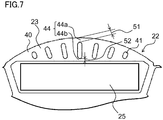
- Fig. 7 is a front view of a rotor of a permanent magnet motor in a third embodiment of the invention.
- connection portion widths 51 and 52 are smaller than an electromagnetic steel plate thickness. Because of this, a flowing around of magnetic flux due to the connection portion 44 decreases, because of which there is an advantage in that the advantage of the slit 41 is more easily obtained.
Landscapes
- Engineering & Computer Science (AREA)
- Power Engineering (AREA)
- Permanent Field Magnets Of Synchronous Machinery (AREA)
- Iron Core Of Rotating Electric Machines (AREA)
Abstract
Description
- The present invention, relating to a permanent magnet motor, relates to a permanent magnet motor used in, for example, an electric power steering system.
- To date, with regard to a rotor of a permanent magnet motor, a structure wherein, in order to improve demagnetization resistance of a permanent magnet, slits aligned so that neighboring intervals are practically equal are provided in a rotor core surface of an IPM (interior permanent magnet) motor has been disclosed (for example, refer to Patent Document 1) .
- Also, with regard to a magnet-embedded rotor of an existing motor, a structure wherein, in order to improve torque ripple, slits inclined in one direction of rotation are provided in a rotor core surface of an IPM motor has been disclosed (for example, refer to Patent Document 2).
- The previously described kinds of existing IPM motor have a main object of achieving an improvement in demagnetization resistance or torque ripple. In the case of demagnetization resistance improvement, there is no need to adopt a complicated structure wherein slits are provided in a rotor surface as disclosed in
Patent Document 1, as it is sufficient to apply a permanent magnet with a high coercive force. Also, in the case of torque ripple reduction, a structure having the kind of perfectly circular external rotor form disclosed inPatent Document 2 is a form such that torque ripple worsens, so is not appropriate. - Generally, an IPM has greater demagnetization resistance than a surface permanent magnet (SPM), and reluctance torque can be utilized, because of which a small motor with a high output can be realized by increasing an amount of current, thereby increasing torque density.
-
- Patent Document 1:
JP-A-2006-081336 - Patent Document 2:
JP-A-2006-014450 - In this case, differing from an SPM, an IPM is such that a face opposing a stator inner diameter forms a rotor core with high magnetic permeability, because of which a magnetic flux that crosses a magnetic pole surface in a circumferential direction increases, and an air gap magnetic flux density is more liable to become locally excessive compared with an SPM.
- An existing permanent magnet motor is such that due to a local increase in magnetic flux density in an air gap, an electromagnetic excitation force proportional to two times the magnetic flux density acts, attempting to cause a stator to transform, because of which there is a problem in that motor vibration noise worsens. As reducing the motor current or enlarging the air gap causes the torque density to decrease, the advantages of reducing size and increasing output with respect to an SPM are cancelled out.
- The invention, having been contrived in order to resolve the heretofore described kind of problem, has an object of providing a permanent magnet motor such that a worsening of motor vibration noise can be restricted while securing a reduction in size and an increase in output, which are advantages of an IPM.
- A permanent magnet motor according to the invention includes a stator, and a rotor having a rotor core disposed opposing an inner side of the stator across an air gap, a permanent magnet disposed in a circumferential direction of the rotor core, and a field pole of the rotor core in which the permanent magnet is disposed, wherein the field pole has a radius smaller than an arc centered on a shaft attached to an inner side of the rotor, a multiple of a slit whose longitudinal axial direction is a radial direction of the rotor core are formed in the field pole, and an interval between a first central line positioned between a multiple of the slit and a second central line positioned between a neighboring multiple of the slit is enlarged as the first central line and the second central line head toward an outer peripheral side of the rotor core.
- According to the permanent magnet motor of the invention, a worsening of vibration noise due to torque ripple and frame vibration can be restricted while securing a reduction in size and an increase in output, which are advantages of an IPM. Therefore, a permanent magnet motor appropriate for use in an electric power steering system or the like can be obtained.
-
- [
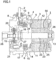
Fig. 1] Fig. 1 is an axial direction sectional view of a permanent magnet motor in a first embodiment of the invention. - [
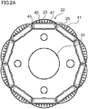
Fig. 2A] Fig. 2A is a front view of a rotor of the permanent magnet motor in the first embodiment of the invention. - [
Fig. 2B] Fig. 2B is a front view of the rotor of the permanent magnet motor in the first embodiment of the invention. - [
Fig. 2C] Fig. 2C is a front view of the rotor of the permanent magnet motor in the first embodiment of the invention. - [
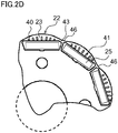
Fig. 2D] Fig. 2D is a front view of the rotor of the permanent magnet motor in the first embodiment of the invention. - [
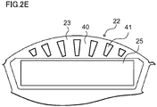
Fig. 2E] Fig. 2E is a front view of the rotor of the permanent magnet motor in the first embodiment of the invention. - [
Fig. 3] Fig. 3 is a front view of a permanent magnet motor in a comparative example. - [
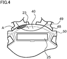
Fig. 4] Fig. 4 is a front view of a permanent magnet motor in a comparative example. - [
Fig. 5] Fig. 5 is a front view of a permanent magnet motor in a comparative example. - [
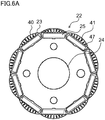
Fig. 6A] Fig. 6A is a front view of a rotor of a permanent magnet motor in a second embodiment of the invention. - [
Fig. 6B] Fig. 6B is a front view of the rotor of the permanent magnet motor in the second embodiment of the invention. - [
Fig. 7] Fig. 7 is a front view of a rotor of a permanent magnet motor in a third embodiment of the invention. - Hereafter, a first embodiment of the invention will be described, based on the drawings.
- Identical reference signs in the drawings indicate identical or corresponding components.
-
Fig. 1 is an axial direction sectional view of a permanent magnet motor in a first embodiment of the invention. - As shown in
Fig. 1 , a permanent magnet motor (hereafter referred to simply as "motor") 1 has arotor core 23 in whose interior a multiple ofpermanent magnets 25 are disposed, has arotor 22 supported so as to rotate freely, a stator winding 5, and astator core 3, and includes astator 12 provided across anair gap 50 on an outer side of therotor 22. - The
stator core 3 is formed by, for example, plate-form electromagnetic steel sheets being stacked, and the three-phase stator winding 5 is wound around thestator core 3 across an insulator 4 made of resin. Thestator windings 5 of each phase are delta-connected by awinding terminal 7 housed in aterminal holder 6 made of resin. Furthermore, aconnection terminal 8 for connecting to alead wire 2 is attached to thewinding terminal 7 of each phase. Theconnection terminal 8 is attached to a connectionterminal base portion 9, and anut 10 for attaching thelead wire 2 to theconnection terminal 8 is housed in an interior of the connectionterminal base portion 9. - The
stator core 3 is press-fitted into aframe 11 made of iron, forming thestator 12 of themotor 1. There is a bottom portion in one end portion of theframe 11, and a rearbearing box portion 13 that houses arear bearing 26 for supporting one end of therotor 22 is formed in a central portion of the bottom portion. Another end portion of theframe 11 is opened, and a spigotjoint portion 14 for linking to ahousing 17 of themotor 1 is formed. Aflange portion 15 having a screw clamping portion for screwing thestator 12 to thehousing 17 of themotor 1 is formed on an outer periphery of thespigot joint portion 14 of theframe 11. An O-ring-form frame grommet 16 for waterproofing is provided between thehousing 17 of themotor 1 and theflange portion 15 of thestator 12. - The
housing 17 of themotor 1 is formed by a die casting of an aluminum alloy, and a front bearingbox 18 that houses a front bearing 27 for supporting one end of therotor 22 is formed in a central portion. Also, aresolver mounting portion 20 for attaching aresolver 19, which is a rotation sensor for detecting an angle of rotation of therotor 22, is formed in a vicinity of thefront bearing box 18 of thehousing 17. A mounting spigotjoint portion 21 for attaching themotor 1 to a mating instrument is provided in an end portion of thehousing 17 on a side opposite to a side on which thestator 12 is attached. - The
rotor 22 includes therotor core 23, which is formed by electromagnetic steel sheets attached to aniron shaft 24 being stacked. Further, either end of theshaft 24 is supported by therear bearing 26 and thefront bearing 27 so as to rotate freely. Aboss 28, which is coupling for linking to a mating instrument, is attached to a front side end portion of theshaft 24. -
Fig. 2A andFig. 2B are front views of a rotor of a permanent magnet motor in the first embodiment of the invention. Also,Fig. 2B is an enlarged view ofFig. 2A . As shown inFig. 2A andFig. 2B , the multiple ofpermanent magnets 25 are disposed in the circumferential direction in therotor core 23 of therotor 22. The multiple ofpermanent magnets 25 are housed and fixed in a multiple of permanent magnet mounting holes 47 disposed at equal intervals in the circumferential direction in therotor core 23, and agap portion 45 is formed on both sides of thepermanent magnet 25.Fig. 2A andFig. 2B are centered on therotor 22. Therefore, a depiction of thestator 12 provided across theair gap 50 on an outer periphery of therotor 22 is omitted. Thestator 12 has thestator core 3, which has a multiple ofteeth 48 and a multiple of slots (not shown), and an armature winding (not shown) wound around theteeth 48 and housed in the slots. - Rather than being a perfect circle centered on the
shaft 24, therotor core 23 in the first embodiment of the invention has a floral form, and includes a multiple ofslits 41 in afield pole 40 of therotor core 23 in which thepermanent magnet 25 is disposed. Thefield pole 40 has a radius smaller than an arc centered on theshaft 24, which is attached on an inner side of therotor 22. Also, the multiple ofslits 41, whose longitudinal axial direction is a radial direction of therotor core 23, are formed in thefield pole 40. - Also, the
rotor core 23 of thefield pole 40 is betweenslits 41, andcentral lines 42 betweenslits 41 are set so as to spread farther apart the nearer thecentral lines 42 come to an outer peripheral side. That is, theslits 41 are provided so that an interval between a firstcentral line 42a betweenslits 41 and a secondcentral line 42b between neighboringslits 41 becomes gradually wider as the firstcentral line 42a and the secondcentral line 42b head toward the outer peripheral side of therotor 22. For example, sevenslits 41 are disposed in each field pole 40 (= one magnetic pole portion). Also, an odd number ofslits 41 are disposed axisymmetrically sandwiching a central slit B disposed in a center of thefield pole 40, and lengths of theslits 41 are axisymmetrically the same. A circumferential direction width of thepermanent magnet 25 is greater than a radial direction width, and thepermanent magnet 25 is of a flat plate magnet form. - Also, a
connection portion 44 is provided in order to integrate thefield pole 40 divided by theslits 41. Thefield pole 40 divided by theslits 41 is integrated by theconnection portion 44. - Also,
Fig. 2C to Fig. 2E are front views of a rotor of a permanent magnet motor that is another working example in the first embodiment of the invention. InFig. 2C , a form of thepermanent magnet 25 is a curved form, but structures excepting thepermanent magnet 25 and a form of a permanent magnet mounting hole are the same as the structures inFig. 2A . - Further still, in
Fig. 2D , a form of therotor core 23 opposing abridge portion 43 is of a perfectlycircular form 46, but structures excepting this form are the same as the structures inFig. 2A . - Also, in
Fig. 2E , a form of theslit 41 is trapezoidal, but structures excepting the form of theslit 41 are the same as the structures inFig. 2A . -
Fig. 3 to Fig. 5 are front views of a permanent magnet motor in a comparative example.Fig. 3 to Fig. 5 show theteeth 48 of thestator 12 provided across theair gap 50 on the outer side of therotor 22. InFig. 3 , the external form of therotor 22 is the perfectlycircular form 46, because of which torque ripple increases. Also, inFig. 4 , noslit 41 is provided in therotor core 23, because of which amagnetic flux 49 crossing thefield pole 40 of therotor core 23 flows, and magnetic flux density in a region A of theair gap 50 increases. Also, inFig. 5 , the intervals between theslits 41 become smaller the nearer to the outer peripheral side of therotor core 23, and there is no longer an advantage of the magnetic flux density of theair gap 50 being dispersed because of theslits 41. - Meanwhile, in the first embodiment of the invention, a particularly noticeable advantage can be exhibited with poles and slots such as 10 poles and 12 slots, 14 poles and 12 slots, or 14 poles and 18 slots, wherein a mode such that a low order electromagnetic excitation force mode is small and vibration noise is liable to increase, for example, a secondary mode all round, occurs.
- One of the
slits 41 is in the center of thefield pole 40. The center of thefield pole 40 is the place in which a sectional area of thefield pole 40 with respect to the crossingmagnetic flux 49 is greatest and themagnetic flux 49 flows most easily, and an advantage in that themagnetic flux 49 is interrupted by theslit 41 is obtained. - When increasing the
slits 41 until magnetic saturation occurs in thefield pole 40, an advantage of restricting vibration noise is easily obtained, but torque decreases, because of which the advantage of restricting vibration noise is obtained, without increasing a physical structure of themotor 1, by the length of the rotor core 23 (the length of thepermanent magnet 25 too) being greater than the length of thestator core 3. -
Fig. 6A andFig. 6B are front views of a rotor of a permanent magnet motor in a second embodiment of the invention. Also,Fig. 6B is an enlarged view ofFig. 6A . As shown inFig. 6A andFig. 6B , the multiple ofpermanent magnets 25 are disposed in the circumferential direction in therotor core 23 of therotor 22. InFig. 6A andFig. 6B , one side of theslit 41 is in an opened state. Specifically, a connection portion (field pole upper side) 44a is provided in theconnection portion 44, but no connection portion (field pole lower side) 44b is provided, the permanentmagnet mounting hole 47 and one side of the multiple ofslits 41 are in a connected state, and one side of the multiple ofslits 41 is in an opened state. When the connection portion (field pole lower side) 44b exists, themagnetic flux 49 of a surface of thefield pole 40 flows around to a back face of thepermanent magnet 25 via the connection portion (field pole lower side) 44b and thebridge portion 43, because of which there is a decrease in themagnetic flux 49 that should flow from thefield pole 40 via theair gap 50 to thestator 12 and become torque. - As the connection portion (field pole lower side) 44b is not provided in the second embodiment of the invention, a reduction in magnetic flux can be further reduced. Therefore, there is less flowing around of magnetic flux due to the connection portion (field pole lower side) 44b than in the first embodiment, because of which there is an advantage in that the advantage of the
slit 41 increases further. -
Fig. 7 is a front view of a rotor of a permanent magnet motor in a third embodiment of the invention. In the third embodiment, as shown inFig. 7 ,connection portion widths 51 and 52 (radial direction widths) are smaller than an electromagnetic steel plate thickness. Because of this, a flowing around of magnetic flux due to theconnection portion 44 decreases, because of which there is an advantage in that the advantage of theslit 41 is more easily obtained. - The embodiments can be freely combined, and each embodiment can be modified or abbreviated as appropriate, without departing from the scope of the invention.
- 1 motor, 2 lead wire, 3 stator core, 4 insulator, 5 stator winding, 6 terminal holder, 7 winding terminal, 8 connection terminal, 9 connection terminal base portion, 10 nut, 11 frame, 12 stator, 13 rear bearing box portion, 14 spigot joint portion, 15 flange portion, 16 frame grommet, 17 housing, 18 front bearing box, 19 resolver, 20 resolver mounting portion, 21 mounting spigot joint portion, 22 rotor, 23 rotor core, 24 shaft, 25 permanent magnet, 26 rear bearing, 27 front bearing, 28 boss, 40 field pole, 41 slit, 42 central line, 42a first central line, 42b second central line, 43 bridge portion, 44 connection portion, 44a connection portion (field pole upper side), 44b connection portion (field pole lower side), 45 gap portion, 46 perfectly circular form, 47 permanent magnet mounting hole, 48 teeth, 49 magnetic flux, 50 air gap, 51 connection portion width, 52 connection portion width
Claims (8)
- A permanent magnet motor, comprising:a stator; anda rotor having a rotor core disposed opposing an inner side of the stator across an air gap, a permanent magnet disposed in a circumferential direction of the rotor core, and a field pole of the rotor core in which the permanent magnet is disposed, whereinthe field pole has a radius smaller than an arc centered on a shaft attached to an inner side of the rotor,a multiple of a slit whose longitudinal axial direction is a radial direction of the rotor core are formed in the field pole, and an interval between a first central line positioned between a multiple of the slit and a second central line positioned between a neighboring multiple of the slit is enlarged as the first central line and the second central line head toward an outer peripheral side of the rotor core.
- The permanent magnet motor according to claim 1, wherein the multiple of slits are disposed axisymmetrically sandwiching the slit disposed in a circumferential direction center of the field pole.
- The permanent magnet motor according to claim 1 or claim 2, wherein an odd number of the multiple of slits are disposed in each field pole.
- The permanent magnet motor according to any one of claim 1 to claim 3, wherein the stator includes a stator core having a multiple of teeth and a multiple of slots, and
an axial direction length of the rotor core is greater than an axial direction length of the stator core. - The permanent magnet motor according to any one of claim 1 to claim 4, wherein the permanent magnet has a flat plate form such that a circumferential direction width is greater than a radial direction width.
- The permanent magnet motor according to any one of claim 1 to claim 5, wherein an external form of the rotor is a floral form.
- The permanent magnet motor according to any one of claim 1 to claim 6, wherein the rotor core is formed by plate-form electromagnetic steel sheets being stacked on the shaft,
a connection portion that integrates the field pole divided by the multiple of slits is provided on an outer peripheral side of the field pole, and
a radial direction width of the connection portion is smaller than a thickness of the electromagnetic steel plate. - The permanent magnet motor according to any one of claim 1 to claim 7, wherein the permanent magnet is fixed in a permanent magnet mounting hole,
the permanent magnet mounting hole and one side of the multiple of slits are in a connected state, and the one side of the multiple of slits is in an opened state.
Applications Claiming Priority (1)
| Application Number | Priority Date | Filing Date | Title |
|---|---|---|---|
| PCT/JP2017/016484 WO2018198217A1 (en) | 2017-04-26 | 2017-04-26 | Permanent magnet-type motor |
Publications (3)
| Publication Number | Publication Date |
|---|---|
| EP3618233A1 true EP3618233A1 (en) | 2020-03-04 |
| EP3618233A4 EP3618233A4 (en) | 2020-04-15 |
| EP3618233B1 EP3618233B1 (en) | 2024-08-07 |
Family
ID=63920377
Family Applications (1)
| Application Number | Title | Priority Date | Filing Date |
|---|---|---|---|
| EP17906893.7A Active EP3618233B1 (en) | 2017-04-26 | 2017-04-26 | Permanent magnet-type motor |
Country Status (5)
| Country | Link |
|---|---|
| US (1) | US11404925B2 (en) |
| EP (1) | EP3618233B1 (en) |
| JP (1) | JPWO2018198217A1 (en) |
| CN (1) | CN110582926A (en) |
| WO (1) | WO2018198217A1 (en) |
Families Citing this family (1)
| Publication number | Priority date | Publication date | Assignee | Title |
|---|---|---|---|---|
| US11901772B2 (en) * | 2018-11-27 | 2024-02-13 | Mitsubishi Electric Corporation | Rotating electrical machine |
Family Cites Families (19)
| Publication number | Priority date | Publication date | Assignee | Title |
|---|---|---|---|---|
| JP4248984B2 (en) * | 2003-09-19 | 2009-04-02 | 東芝キヤリア株式会社 | Permanent magnet motor |
| JP4127683B2 (en) | 2004-06-24 | 2008-07-30 | 三菱電機株式会社 | Embedded magnet rotor |
| JP4091933B2 (en) | 2004-09-01 | 2008-05-28 | 三菱電機株式会社 | Permanent magnet motor |
| JP2006081336A (en) | 2004-09-10 | 2006-03-23 | Nissan Motor Co Ltd | Convex polarity changing rotor of rotating electrical machine |
| JP4709132B2 (en) | 2006-12-28 | 2011-06-22 | 三菱電機株式会社 | Rotor of permanent magnet embedded motor, motor for blower and motor for compressor |
| JP5334555B2 (en) * | 2008-12-16 | 2013-11-06 | 三菱電機株式会社 | Electric motor and refrigerant compressor equipped with the same |
| US8179011B2 (en) * | 2008-12-17 | 2012-05-15 | Asmo Co., Ltd. | Brushless motor |
| WO2011033397A2 (en) * | 2009-09-18 | 2011-03-24 | Brusa Elektronik Ag | Permanent magnet exited synchronous machine with embedded magnets |
| JP5208084B2 (en) * | 2009-10-09 | 2013-06-12 | 三菱電機株式会社 | Rotor, blower and compressor of embedded permanent magnet motor |
| JP5478461B2 (en) | 2010-11-09 | 2014-04-23 | 三菱電機株式会社 | Electric motor and compressor |
| JP5945728B2 (en) * | 2011-01-28 | 2016-07-05 | パナソニックIpマネジメント株式会社 | Brushless motor and electric device equipped with the same |
| CN103891102B (en) * | 2011-10-24 | 2016-08-24 | 三菱电机株式会社 | Rotor, compressor and the refrigerating air conditioning device of permanent magnet embedded-type electric motivation |
| EP2602912A2 (en) * | 2011-12-05 | 2013-06-12 | Samsung Electronics Co., Ltd | Brushless motor |
| US20150084468A1 (en) * | 2012-01-30 | 2015-03-26 | Mitsubishi Electric Corporation | Rotor for permanent-magnet-embedded electric motor, electric motor including the rotor, compressor including the electric motor, and air conditioner including the compressor |
| EP2916434B1 (en) * | 2012-11-01 | 2017-07-19 | Mitsubishi Electric Corporation | Electric motor with embedded permanent magnet, compressor, and refrigeration and air conditioning equipment |
| JP5985358B2 (en) * | 2012-11-02 | 2016-09-06 | 株式会社クボタ | Permanent magnet synchronous motor |
| CN105009420B (en) * | 2013-03-14 | 2018-05-11 | 艾默生电气公司 | Rotors and stators for electric machines |
| DE102015004669A1 (en) * | 2014-04-15 | 2016-02-18 | Asmo Co., Ltd. | ENGINE |
| US10374474B2 (en) | 2015-09-30 | 2019-08-06 | Mitsubishi Electric Corporation | Permanent magnet motor |
-
2017
- 2017-04-26 CN CN201780089811.5A patent/CN110582926A/en active Pending
- 2017-04-26 JP JP2019514939A patent/JPWO2018198217A1/en active Pending
- 2017-04-26 EP EP17906893.7A patent/EP3618233B1/en active Active
- 2017-04-26 WO PCT/JP2017/016484 patent/WO2018198217A1/en not_active Ceased
- 2017-04-26 US US16/477,606 patent/US11404925B2/en active Active
Also Published As
| Publication number | Publication date |
|---|---|
| US20200127509A1 (en) | 2020-04-23 |
| CN110582926A (en) | 2019-12-17 |
| EP3618233B1 (en) | 2024-08-07 |
| JPWO2018198217A1 (en) | 2019-11-07 |
| EP3618233A4 (en) | 2020-04-15 |
| WO2018198217A1 (en) | 2018-11-01 |
| US11404925B2 (en) | 2022-08-02 |
Similar Documents
| Publication | Publication Date | Title |
|---|---|---|
| US8766506B2 (en) | Stator core | |
| JP5673640B2 (en) | Hybrid excitation type rotating electric machine | |
| JP5506836B2 (en) | Magnet generator | |
| US10862357B2 (en) | Permanent-magnet-embedded electric motor, blower, and refrigerating air conditioner | |
| US10784733B2 (en) | Motor and air conditioning apparatus | |
| EP2784909A1 (en) | Electric motor | |
| US10680475B2 (en) | Rotor for rotary electric machine | |
| US20120306298A1 (en) | Switched reluctance motor | |
| CN113597725B (en) | synchronous reluctance motor | |
| JP3703907B2 (en) | Brushless DC motor | |
| JP7501693B2 (en) | Rotating electric machine and method for manufacturing the same | |
| US20180316230A1 (en) | Stator assembly | |
| US11264880B2 (en) | Permanent magnet motor | |
| EP3618233B1 (en) | Permanent magnet-type motor | |
| CN114556749A (en) | Rotor and motor | |
| JP7401380B2 (en) | permanent magnet electric motor | |
| EP3098942B1 (en) | Rotor | |
| JP6428458B2 (en) | Embedded magnet type motor | |
| JP2012080697A (en) | Motor | |
| JP2001178037A (en) | Permanent magnet type rotating electric machine | |
| JPH1028344A (en) | Motor | |
| JP7401381B2 (en) | permanent magnet electric motor | |
| JP2001086718A (en) | Self-starting permanent magnet synchronous motor and method of manufacturing the same | |
| JP2009033925A (en) | Synchronous reluctance motor | |
| JP2011010488A (en) | Small motor |
Legal Events
| Date | Code | Title | Description |
|---|---|---|---|
| STAA | Information on the status of an ep patent application or granted ep patent |
Free format text: STATUS: THE INTERNATIONAL PUBLICATION HAS BEEN MADE |
|
| PUAI | Public reference made under article 153(3) epc to a published international application that has entered the european phase |
Free format text: ORIGINAL CODE: 0009012 |
|
| STAA | Information on the status of an ep patent application or granted ep patent |
Free format text: STATUS: REQUEST FOR EXAMINATION WAS MADE |
|
| 17P | Request for examination filed |
Effective date: 20190628 |
|
| AK | Designated contracting states |
Kind code of ref document: A1 Designated state(s): AL AT BE BG CH CY CZ DE DK EE ES FI FR GB GR HR HU IE IS IT LI LT LU LV MC MK MT NL NO PL PT RO RS SE SI SK SM TR |
|
| AX | Request for extension of the european patent |
Extension state: BA ME |
|
| A4 | Supplementary search report drawn up and despatched |
Effective date: 20200318 |
|
| RIC1 | Information provided on ipc code assigned before grant |
Ipc: H02K 1/27 20060101AFI20200312BHEP |
|
| DAV | Request for validation of the european patent (deleted) | ||
| DAX | Request for extension of the european patent (deleted) | ||
| STAA | Information on the status of an ep patent application or granted ep patent |
Free format text: STATUS: EXAMINATION IS IN PROGRESS |
|
| 17Q | First examination report despatched |
Effective date: 20210809 |
|
| REG | Reference to a national code |
Ref country code: DE Free format text: PREVIOUS MAIN CLASS: H02K0001270000 Ref country code: DE Ref legal event code: R079 Ref document number: 602017083981 Country of ref document: DE Free format text: PREVIOUS MAIN CLASS: H02K0001270000 Ipc: H02K0001276000 |
|
| GRAP | Despatch of communication of intention to grant a patent |
Free format text: ORIGINAL CODE: EPIDOSNIGR1 |
|
| STAA | Information on the status of an ep patent application or granted ep patent |
Free format text: STATUS: GRANT OF PATENT IS INTENDED |
|
| RIC1 | Information provided on ipc code assigned before grant |
Ipc: H02K 1/276 20220101AFI20240229BHEP |
|
| INTG | Intention to grant announced |
Effective date: 20240315 |
|
| RIN1 | Information on inventor provided before grant (corrected) |
Inventor name: SUGI, NATSUMI Inventor name: OKAZAKI, MASAFUMI Inventor name: AKUTSU, SATORU Inventor name: TAKIZAWA, YUJI |
|
| GRAS | Grant fee paid |
Free format text: ORIGINAL CODE: EPIDOSNIGR3 |
|
| GRAA | (expected) grant |
Free format text: ORIGINAL CODE: 0009210 |
|
| STAA | Information on the status of an ep patent application or granted ep patent |
Free format text: STATUS: THE PATENT HAS BEEN GRANTED |
|
| AK | Designated contracting states |
Kind code of ref document: B1 Designated state(s): AL AT BE BG CH CY CZ DE DK EE ES FI FR GB GR HR HU IE IS IT LI LT LU LV MC MK MT NL NO PL PT RO RS SE SI SK SM TR |
|
| REG | Reference to a national code |
Ref country code: GB Ref legal event code: FG4D |
|
| REG | Reference to a national code |
Ref country code: CH Ref legal event code: EP |
|
| REG | Reference to a national code |
Ref country code: DE Ref legal event code: R096 Ref document number: 602017083981 Country of ref document: DE |
|
| REG | Reference to a national code |
Ref country code: IE Ref legal event code: FG4D |
|
| REG | Reference to a national code |
Ref country code: LT Ref legal event code: MG9D |
|
| REG | Reference to a national code |
Ref country code: NL Ref legal event code: MP Effective date: 20240807 |
|
| PG25 | Lapsed in a contracting state [announced via postgrant information from national office to epo] |
Ref country code: NO Free format text: LAPSE BECAUSE OF FAILURE TO SUBMIT A TRANSLATION OF THE DESCRIPTION OR TO PAY THE FEE WITHIN THE PRESCRIBED TIME-LIMIT Effective date: 20241107 |
|
| REG | Reference to a national code |
Ref country code: AT Ref legal event code: MK05 Ref document number: 1712017 Country of ref document: AT Kind code of ref document: T Effective date: 20240807 |
|
| PG25 | Lapsed in a contracting state [announced via postgrant information from national office to epo] |
Ref country code: NL Free format text: LAPSE BECAUSE OF FAILURE TO SUBMIT A TRANSLATION OF THE DESCRIPTION OR TO PAY THE FEE WITHIN THE PRESCRIBED TIME-LIMIT Effective date: 20240807 Ref country code: FI Free format text: LAPSE BECAUSE OF FAILURE TO SUBMIT A TRANSLATION OF THE DESCRIPTION OR TO PAY THE FEE WITHIN THE PRESCRIBED TIME-LIMIT Effective date: 20240807 Ref country code: PL Free format text: LAPSE BECAUSE OF FAILURE TO SUBMIT A TRANSLATION OF THE DESCRIPTION OR TO PAY THE FEE WITHIN THE PRESCRIBED TIME-LIMIT Effective date: 20240807 Ref country code: GR Free format text: LAPSE BECAUSE OF FAILURE TO SUBMIT A TRANSLATION OF THE DESCRIPTION OR TO PAY THE FEE WITHIN THE PRESCRIBED TIME-LIMIT Effective date: 20241108 Ref country code: PT Free format text: LAPSE BECAUSE OF FAILURE TO SUBMIT A TRANSLATION OF THE DESCRIPTION OR TO PAY THE FEE WITHIN THE PRESCRIBED TIME-LIMIT Effective date: 20241209 |
|
| PG25 | Lapsed in a contracting state [announced via postgrant information from national office to epo] |
Ref country code: BG Free format text: LAPSE BECAUSE OF FAILURE TO SUBMIT A TRANSLATION OF THE DESCRIPTION OR TO PAY THE FEE WITHIN THE PRESCRIBED TIME-LIMIT Effective date: 20240807 |
|
| PG25 | Lapsed in a contracting state [announced via postgrant information from national office to epo] |
Ref country code: LV Free format text: LAPSE BECAUSE OF FAILURE TO SUBMIT A TRANSLATION OF THE DESCRIPTION OR TO PAY THE FEE WITHIN THE PRESCRIBED TIME-LIMIT Effective date: 20240807 |
|
| PG25 | Lapsed in a contracting state [announced via postgrant information from national office to epo] |
Ref country code: IS Free format text: LAPSE BECAUSE OF FAILURE TO SUBMIT A TRANSLATION OF THE DESCRIPTION OR TO PAY THE FEE WITHIN THE PRESCRIBED TIME-LIMIT Effective date: 20241207 Ref country code: AT Free format text: LAPSE BECAUSE OF FAILURE TO SUBMIT A TRANSLATION OF THE DESCRIPTION OR TO PAY THE FEE WITHIN THE PRESCRIBED TIME-LIMIT Effective date: 20240807 |
|
| PG25 | Lapsed in a contracting state [announced via postgrant information from national office to epo] |
Ref country code: HR Free format text: LAPSE BECAUSE OF FAILURE TO SUBMIT A TRANSLATION OF THE DESCRIPTION OR TO PAY THE FEE WITHIN THE PRESCRIBED TIME-LIMIT Effective date: 20240807 |
|
| PG25 | Lapsed in a contracting state [announced via postgrant information from national office to epo] |
Ref country code: ES Free format text: LAPSE BECAUSE OF FAILURE TO SUBMIT A TRANSLATION OF THE DESCRIPTION OR TO PAY THE FEE WITHIN THE PRESCRIBED TIME-LIMIT Effective date: 20240807 Ref country code: RS Free format text: LAPSE BECAUSE OF FAILURE TO SUBMIT A TRANSLATION OF THE DESCRIPTION OR TO PAY THE FEE WITHIN THE PRESCRIBED TIME-LIMIT Effective date: 20241107 |
|
| PG25 | Lapsed in a contracting state [announced via postgrant information from national office to epo] |
Ref country code: RS Free format text: LAPSE BECAUSE OF FAILURE TO SUBMIT A TRANSLATION OF THE DESCRIPTION OR TO PAY THE FEE WITHIN THE PRESCRIBED TIME-LIMIT Effective date: 20241107 Ref country code: PT Free format text: LAPSE BECAUSE OF FAILURE TO SUBMIT A TRANSLATION OF THE DESCRIPTION OR TO PAY THE FEE WITHIN THE PRESCRIBED TIME-LIMIT Effective date: 20241209 Ref country code: PL Free format text: LAPSE BECAUSE OF FAILURE TO SUBMIT A TRANSLATION OF THE DESCRIPTION OR TO PAY THE FEE WITHIN THE PRESCRIBED TIME-LIMIT Effective date: 20240807 Ref country code: NO Free format text: LAPSE BECAUSE OF FAILURE TO SUBMIT A TRANSLATION OF THE DESCRIPTION OR TO PAY THE FEE WITHIN THE PRESCRIBED TIME-LIMIT Effective date: 20241107 Ref country code: NL Free format text: LAPSE BECAUSE OF FAILURE TO SUBMIT A TRANSLATION OF THE DESCRIPTION OR TO PAY THE FEE WITHIN THE PRESCRIBED TIME-LIMIT Effective date: 20240807 Ref country code: LV Free format text: LAPSE BECAUSE OF FAILURE TO SUBMIT A TRANSLATION OF THE DESCRIPTION OR TO PAY THE FEE WITHIN THE PRESCRIBED TIME-LIMIT Effective date: 20240807 Ref country code: IS Free format text: LAPSE BECAUSE OF FAILURE TO SUBMIT A TRANSLATION OF THE DESCRIPTION OR TO PAY THE FEE WITHIN THE PRESCRIBED TIME-LIMIT Effective date: 20241207 Ref country code: HR Free format text: LAPSE BECAUSE OF FAILURE TO SUBMIT A TRANSLATION OF THE DESCRIPTION OR TO PAY THE FEE WITHIN THE PRESCRIBED TIME-LIMIT Effective date: 20240807 Ref country code: GR Free format text: LAPSE BECAUSE OF FAILURE TO SUBMIT A TRANSLATION OF THE DESCRIPTION OR TO PAY THE FEE WITHIN THE PRESCRIBED TIME-LIMIT Effective date: 20241108 Ref country code: FI Free format text: LAPSE BECAUSE OF FAILURE TO SUBMIT A TRANSLATION OF THE DESCRIPTION OR TO PAY THE FEE WITHIN THE PRESCRIBED TIME-LIMIT Effective date: 20240807 Ref country code: ES Free format text: LAPSE BECAUSE OF FAILURE TO SUBMIT A TRANSLATION OF THE DESCRIPTION OR TO PAY THE FEE WITHIN THE PRESCRIBED TIME-LIMIT Effective date: 20240807 Ref country code: BG Free format text: LAPSE BECAUSE OF FAILURE TO SUBMIT A TRANSLATION OF THE DESCRIPTION OR TO PAY THE FEE WITHIN THE PRESCRIBED TIME-LIMIT Effective date: 20240807 Ref country code: AT Free format text: LAPSE BECAUSE OF FAILURE TO SUBMIT A TRANSLATION OF THE DESCRIPTION OR TO PAY THE FEE WITHIN THE PRESCRIBED TIME-LIMIT Effective date: 20240807 |
|
| PG25 | Lapsed in a contracting state [announced via postgrant information from national office to epo] |
Ref country code: SM Free format text: LAPSE BECAUSE OF FAILURE TO SUBMIT A TRANSLATION OF THE DESCRIPTION OR TO PAY THE FEE WITHIN THE PRESCRIBED TIME-LIMIT Effective date: 20240807 Ref country code: DK Free format text: LAPSE BECAUSE OF FAILURE TO SUBMIT A TRANSLATION OF THE DESCRIPTION OR TO PAY THE FEE WITHIN THE PRESCRIBED TIME-LIMIT Effective date: 20240807 Ref country code: RO Free format text: LAPSE BECAUSE OF FAILURE TO SUBMIT A TRANSLATION OF THE DESCRIPTION OR TO PAY THE FEE WITHIN THE PRESCRIBED TIME-LIMIT Effective date: 20240807 |
|
| PG25 | Lapsed in a contracting state [announced via postgrant information from national office to epo] |
Ref country code: EE Free format text: LAPSE BECAUSE OF FAILURE TO SUBMIT A TRANSLATION OF THE DESCRIPTION OR TO PAY THE FEE WITHIN THE PRESCRIBED TIME-LIMIT Effective date: 20240807 |
|
| PG25 | Lapsed in a contracting state [announced via postgrant information from national office to epo] |
Ref country code: CZ Free format text: LAPSE BECAUSE OF FAILURE TO SUBMIT A TRANSLATION OF THE DESCRIPTION OR TO PAY THE FEE WITHIN THE PRESCRIBED TIME-LIMIT Effective date: 20240807 |
|
| PG25 | Lapsed in a contracting state [announced via postgrant information from national office to epo] |
Ref country code: SK Free format text: LAPSE BECAUSE OF FAILURE TO SUBMIT A TRANSLATION OF THE DESCRIPTION OR TO PAY THE FEE WITHIN THE PRESCRIBED TIME-LIMIT Effective date: 20240807 |
|
| REG | Reference to a national code |
Ref country code: DE Ref legal event code: R097 Ref document number: 602017083981 Country of ref document: DE |
|
| PLBE | No opposition filed within time limit |
Free format text: ORIGINAL CODE: 0009261 |
|
| STAA | Information on the status of an ep patent application or granted ep patent |
Free format text: STATUS: NO OPPOSITION FILED WITHIN TIME LIMIT |
|
| PGFP | Annual fee paid to national office [announced via postgrant information from national office to epo] |
Ref country code: DE Payment date: 20250305 Year of fee payment: 9 |
|
| 26N | No opposition filed |
Effective date: 20250508 |
|
| PG25 | Lapsed in a contracting state [announced via postgrant information from national office to epo] |
Ref country code: SE Free format text: LAPSE BECAUSE OF FAILURE TO SUBMIT A TRANSLATION OF THE DESCRIPTION OR TO PAY THE FEE WITHIN THE PRESCRIBED TIME-LIMIT Effective date: 20240807 |
|
| P01 | Opt-out of the competence of the unified patent court (upc) registered |
Free format text: CASE NUMBER: UPC_APP_4903_3618233/2025 Effective date: 20250827 |
|
| REG | Reference to a national code |
Ref country code: CH Ref legal event code: H13 Free format text: ST27 STATUS EVENT CODE: U-0-0-H10-H13 (AS PROVIDED BY THE NATIONAL OFFICE) Effective date: 20251125 |
|
| PG25 | Lapsed in a contracting state [announced via postgrant information from national office to epo] |
Ref country code: LU Free format text: LAPSE BECAUSE OF NON-PAYMENT OF DUE FEES Effective date: 20250426 |
|
| PG25 | Lapsed in a contracting state [announced via postgrant information from national office to epo] |
Ref country code: MC Free format text: LAPSE BECAUSE OF FAILURE TO SUBMIT A TRANSLATION OF THE DESCRIPTION OR TO PAY THE FEE WITHIN THE PRESCRIBED TIME-LIMIT Effective date: 20240807 |
|
| GBPC | Gb: european patent ceased through non-payment of renewal fee |
Effective date: 20250426 |
|
| REG | Reference to a national code |
Ref country code: BE Ref legal event code: MM Effective date: 20250430 |
|
| PG25 | Lapsed in a contracting state [announced via postgrant information from national office to epo] |
Ref country code: GB Free format text: LAPSE BECAUSE OF NON-PAYMENT OF DUE FEES Effective date: 20250426 |
|
| PG25 | Lapsed in a contracting state [announced via postgrant information from national office to epo] |
Ref country code: BE Free format text: LAPSE BECAUSE OF NON-PAYMENT OF DUE FEES Effective date: 20250430 |
|
| PG25 | Lapsed in a contracting state [announced via postgrant information from national office to epo] |
Ref country code: CH Free format text: LAPSE BECAUSE OF NON-PAYMENT OF DUE FEES Effective date: 20250430 |
|
| PG25 | Lapsed in a contracting state [announced via postgrant information from national office to epo] |
Ref country code: IT Free format text: LAPSE BECAUSE OF FAILURE TO SUBMIT A TRANSLATION OF THE DESCRIPTION OR TO PAY THE FEE WITHIN THE PRESCRIBED TIME-LIMIT Effective date: 20240807 |
|
| PG25 | Lapsed in a contracting state [announced via postgrant information from national office to epo] |
Ref country code: IE Free format text: LAPSE BECAUSE OF NON-PAYMENT OF DUE FEES Effective date: 20250426 |
|
| PGFP | Annual fee paid to national office [announced via postgrant information from national office to epo] |
Ref country code: FR Payment date: 20260309 Year of fee payment: 10 |