EP3618210B1 - Junction box and offshore power generation system using junction box - Google Patents
Junction box and offshore power generation system using junction box Download PDFInfo
- Publication number
- EP3618210B1 EP3618210B1 EP17907009.9A EP17907009A EP3618210B1 EP 3618210 B1 EP3618210 B1 EP 3618210B1 EP 17907009 A EP17907009 A EP 17907009A EP 3618210 B1 EP3618210 B1 EP 3618210B1
- Authority
- EP
- European Patent Office
- Prior art keywords
- cable
- junction box
- cables
- connector
- power generation
- Prior art date
- Legal status (The legal status is an assumption and is not a legal conclusion. Google has not performed a legal analysis and makes no representation as to the accuracy of the status listed.)
- Active
Links
Images



Classifications
-
- H—ELECTRICITY
- H02—GENERATION; CONVERSION OR DISTRIBUTION OF ELECTRIC POWER
- H02G—INSTALLATION OF ELECTRIC CABLES OR LINES, OR OF COMBINED OPTICAL AND ELECTRIC CABLES OR LINES
- H02G15/00—Cable fittings
- H02G15/08—Cable junctions
- H02G15/10—Cable junctions protected by boxes, e.g. by distribution, connection or junction boxes
- H02G15/16—Cable junctions protected by boxes, e.g. by distribution, connection or junction boxes structurally associated with support for line-connecting terminals within the box
-
- G—PHYSICS
- G02—OPTICS
- G02B—OPTICAL ELEMENTS, SYSTEMS OR APPARATUS
- G02B6/00—Light guides; Structural details of arrangements comprising light guides and other optical elements, e.g. couplings
- G02B6/44—Mechanical structures for providing tensile strength and external protection for fibres, e.g. optical transmission cables
- G02B6/4439—Auxiliary devices
- G02B6/444—Systems or boxes with surplus lengths
- G02B6/4441—Boxes
- G02B6/4448—Electro-optic
-
- H—ELECTRICITY
- H02—GENERATION; CONVERSION OR DISTRIBUTION OF ELECTRIC POWER
- H02G—INSTALLATION OF ELECTRIC CABLES OR LINES, OR OF COMBINED OPTICAL AND ELECTRIC CABLES OR LINES
- H02G1/00—Methods or apparatus specially adapted for installing, maintaining, repairing or dismantling electric cables or lines
- H02G1/06—Methods or apparatus specially adapted for installing, maintaining, repairing or dismantling electric cables or lines for laying cables, e.g. laying apparatus on vehicle
- H02G1/10—Methods or apparatus specially adapted for installing, maintaining, repairing or dismantling electric cables or lines for laying cables, e.g. laying apparatus on vehicle in or under water
-
- H—ELECTRICITY
- H02—GENERATION; CONVERSION OR DISTRIBUTION OF ELECTRIC POWER
- H02G—INSTALLATION OF ELECTRIC CABLES OR LINES, OR OF COMBINED OPTICAL AND ELECTRIC CABLES OR LINES
- H02G15/00—Cable fittings
- H02G15/08—Cable junctions
-
- H—ELECTRICITY
- H02—GENERATION; CONVERSION OR DISTRIBUTION OF ELECTRIC POWER
- H02G—INSTALLATION OF ELECTRIC CABLES OR LINES, OR OF COMBINED OPTICAL AND ELECTRIC CABLES OR LINES
- H02G15/00—Cable fittings
- H02G15/08—Cable junctions
- H02G15/10—Cable junctions protected by boxes, e.g. by distribution, connection or junction boxes
-
- H—ELECTRICITY
- H02—GENERATION; CONVERSION OR DISTRIBUTION OF ELECTRIC POWER
- H02G—INSTALLATION OF ELECTRIC CABLES OR LINES, OR OF COMBINED OPTICAL AND ELECTRIC CABLES OR LINES
- H02G15/00—Cable fittings
- H02G15/08—Cable junctions
- H02G15/10—Cable junctions protected by boxes, e.g. by distribution, connection or junction boxes
- H02G15/12—Cable junctions protected by boxes, e.g. by distribution, connection or junction boxes for incorporating transformers, loading coils or amplifiers
- H02G15/14—Cable junctions protected by boxes, e.g. by distribution, connection or junction boxes for incorporating transformers, loading coils or amplifiers specially adapted for submarine cables
-
- H—ELECTRICITY
- H02—GENERATION; CONVERSION OR DISTRIBUTION OF ELECTRIC POWER
- H02G—INSTALLATION OF ELECTRIC CABLES OR LINES, OR OF COMBINED OPTICAL AND ELECTRIC CABLES OR LINES
- H02G9/00—Installations of electric cables or lines in or on the ground or water
- H02G9/12—Installations of electric cables or lines in or on the ground or water supported on or from floats, e.g. in water
-
- G—PHYSICS
- G02—OPTICS
- G02B—OPTICAL ELEMENTS, SYSTEMS OR APPARATUS
- G02B6/00—Light guides; Structural details of arrangements comprising light guides and other optical elements, e.g. couplings
- G02B6/24—Coupling light guides
- G02B6/36—Mechanical coupling means
- G02B6/38—Mechanical coupling means having fibre to fibre mating means
- G02B6/3807—Dismountable connectors, i.e. comprising plugs
- G02B6/3897—Connectors fixed to housings, casing, frames or circuit boards
-
- G—PHYSICS
- G02—OPTICS
- G02B—OPTICAL ELEMENTS, SYSTEMS OR APPARATUS
- G02B6/00—Light guides; Structural details of arrangements comprising light guides and other optical elements, e.g. couplings
- G02B6/44—Mechanical structures for providing tensile strength and external protection for fibres, e.g. optical transmission cables
- G02B6/4401—Optical cables
- G02B6/4415—Cables for special applications
- G02B6/4416—Heterogeneous cables
-
- G—PHYSICS
- G02—OPTICS
- G02B—OPTICAL ELEMENTS, SYSTEMS OR APPARATUS
- G02B6/00—Light guides; Structural details of arrangements comprising light guides and other optical elements, e.g. couplings
- G02B6/44—Mechanical structures for providing tensile strength and external protection for fibres, e.g. optical transmission cables
- G02B6/4401—Optical cables
- G02B6/4415—Cables for special applications
- G02B6/4427—Pressure resistant cables, e.g. undersea cables
- G02B6/4428—Penetrator systems in pressure-resistant devices
-
- Y—GENERAL TAGGING OF NEW TECHNOLOGICAL DEVELOPMENTS; GENERAL TAGGING OF CROSS-SECTIONAL TECHNOLOGIES SPANNING OVER SEVERAL SECTIONS OF THE IPC; TECHNICAL SUBJECTS COVERED BY FORMER USPC CROSS-REFERENCE ART COLLECTIONS [XRACs] AND DIGESTS
- Y02—TECHNOLOGIES OR APPLICATIONS FOR MITIGATION OR ADAPTATION AGAINST CLIMATE CHANGE
- Y02E—REDUCTION OF GREENHOUSE GAS [GHG] EMISSIONS, RELATED TO ENERGY GENERATION, TRANSMISSION OR DISTRIBUTION
- Y02E10/00—Energy generation through renewable energy sources
- Y02E10/30—Energy from the sea, e.g. using wave energy or salinity gradient
Definitions
- the subject matter herein generally relates to electrical junction boxes, especially relates to a junction box suitable for use in marine engineering and an offshore power generation system using the junction box.
- Offshore oil and gas, wave energy, and dynamic platforms have become widespread. Offshore power generation platforms which are mobile play an important role in the future use of new energy sources, such as wave power generation which uses offshore tidal energy to generate electricity. Long-term operations at sea and in an ocean environment may be problematic for junction boxes to establish reliable connections for cables at sea. Prior art junction boxes include the ones disclosed in US2003/021556A1 and EP2393220A1 .
- a junction box according to the invention is defined in independent claim 1.
- Preferred embodiments are defined in dependent claims 2-8.
- a junction box comprising: a protecting case; an anchoring device; a cable connector; an optical unit connection box; an optical fiber connector; and an electrical connector; wherein each of the cable connector and the optical unit connection box is received in the protecting case, each of the anchoring device, the optical fiber connector and the electrical connector is mounted on the protecting case.
- the protecting case comprises a main body and a cover fixed to an end of the main body, the anchoring device is fixed at an end of the main body away from the cover, the cable connector and the optical unit connection box are received in the main body, and the optical fiber connector and the electrical connector are mounted on the cover.
- the anchoring device comprises a fixing member and two wire passing members connected to the fixing member, the fixing member defines a line channel, each of the two wire passing members defines a wire passing hole.
- the fixing member comprises a positioning portion, a protrusion protruding from one end of the positioning portion, and a connecting portion connected to the other end of the positioning portion, the line channel penetrates the positioning portion, the protrusion and the connecting portion.
- the junction box further comprises a fixing plate, the fixing plate is received in the protecting case and is fixed to the cover, the cable connector and the optical unit connection box are mounted on the fixing plate.
- the cable connector comprises a front joint, a rear joint, a sleeve interface, an intermediate joint, a plug head, and a closing head cover
- the sleeve interface and the intermediate joint are respectively positioned at both ends of the front joint
- the sleeve interface and the intermediate joint are connected by a stud bolt
- the intermediate joint and the plug head are respectively disposed at two ends of the rear joint
- the intermediate joint and the plug head are connected by the other stud bolt
- the closing head cover is sealed at an end of the plug head away from the rear joint.
- the optical unit connection box comprises a disk tray and two fixing members respectively disposed at two ends of the disk tray, the disk tray comprises a disk body and a lid that is covered on the disk body, the fixing member is configured to fix cables, and the disk tray is configured to receive optical fibers.
- the fixing member comprises a fixing head, two sleeves connected to the fixing head, and two sealing members positioned in the two sleeves, the fixing head is fixed to the disk body.
- a offshore power generation system comprising: at least one power generation platform; and above junction box; wherein optical cables of the power generating platform are connected to the optical fiber connector of the junction box, and electronic cables of the power generating platform are connected to the electrical connector, and the cable connector is connected to the electronic cables entering from the anchoring device, and the optical unit connection box is connected the optical cables entering from the anchoring device.
- the power generation platform is a wave energy generator.
- the offshore power generation system realizes connection of the one or more power generation platforms through the cable and the junction box to form a chain or mesh power generation system.
- the anchoring device, the cable connector, the optical unit connection box, the fiber connector, and the electrical connector, ensure high structural and sealing performance of the cables in the junction box.
- substantially is defined to be essentially conforming to the particular dimension, shape, or other feature that the term modifies, such that the component need not be exact.
- substantially cylindrical means that the object resembles a cylinder, but can have one or more deviations from a true cylinder.
- comprising when utilized, means “including, but not necessarily limited to”; it specifically indicates open-ended inclusion or membership in the so-described combination, group, series, and the like.
- the references “a plurality of” and “a number of” mean “at least two.”
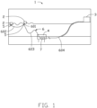
- FIG. 1 is a schematic view of an offshore power generation system 1 according to an embodiment.
- the offshore power generation system 1 includes at least one power generation platform 2 positioned at sea, a base station 3 positioned on the land, a fixing device 4 positioned at the seabed, at least one junction box 5, and a plurality of cables 6.
- the base station 3 includes a substation.
- the power generation platform 2 is configured to generate power using marine resources, such as wave energy.
- the base station 3 is configured to change the voltage of the power generated by the power generation platform 2 to deliver the power onwardly.
- the number of the power generating platforms 2 shown in FIG. 1 is two.
- the number of the power generating platforms 2 can be one, or three or more, correspondingly, the number of the junction boxes 5 can be one, or two or more. In FIG. 1 , the number of the junction boxes 5 is also two.
- the plurality of cables 6 is defined to include a first cable 601, a second cable 602, a third cable 603, and a fourth cable 604.
- the first cable 601 is connected the power generation platform 2 with corresponding junction box 5.
- the second cable 602 is a dynamic cable connected between two junction boxes 5.
- the third cable 603 is a dynamic cable connecting one of the junction boxes 5 and the fourth cable 604.
- the fourth cable 604 is a static cable connecting the third cable 603 with the base station 3.
- the third cable 603 and the fourth cable 604 are connected by a joint 401, and the joint 401 is positioned on the fixing device 4.
- the fixing device 4 is fixed to the seabed for positioning the junction of the third cable 603 and the fourth cable 604.
- the offshore power generation system 1 is a wave power generation system, and accordingly, the power generation platform 2 is a wave energy generator.
- the first cable 601 is a cable of the generator.
- the offshore power generation system 1 is not limited to being the wave power generation system, it can be other power generation system that generates power by other means.
- the offshore power generation system 1 connects the power generation platforms 2 (i.e., the two generators) in series to form a chain or mesh power generation system.
- the offshore power generation system 1 further includes at least one lifting device 7.
- the at least one lifting device 7 is connected to a power generating platform 2 for moving the offshore power generation system 1.
- the at least one lifting device 7 can be connected to a body of a generator.
- Each junction box 5 is mounted on one of the lifting devices 7. In the embodiment, the junction box 5 is fixed to one side of the lifting device 7 by a fixing frame 8, and the junction box 5 and the lifting device 7 are beside each other.
- the junction box 5 includes a protecting case 10, an anchoring device 20, a fixing plate 30, a cable connector 40, an optical unit connection box 50, an optical fiber connector 60, and an electrical connector 70.
- the protecting case 10 is hollow and accommodates the fixing plate 30, the cable connector 40, and the optical unit connection box 50.
- the anchoring device 20 is mounted at an end of the protection casing 10 for fixing cables (such as the second cable 602 and the third cable 603).
- the fixing plate 30 is fixedly positioned in the protecting case 10 for positioning the cable connector 40 and the optical unit connection box 50.
- the cable connector 40 is fixed to the fixing plate 30 and received in the protecting case 10.
- the cable connector 40 is a plug-in terminal connector inside the junction box 5 for ensuring power collection, connection, and grounded shielding between the dynamic cable and the power generation platform 2.
- the optical unit connection box 50 is fixed to the fixing plate 30 and received in the protective case 10 for ensuring communication between the two power generation platforms 2, the power generation platform 2, and the base station 3.
- the optical fiber connector 60 is mounted on the protecting case 10, and a part of the optical fiber connector 60 passes through the protecting case 10 to be received in the protecting case 10.
- the fiber optic connector 60 is an internal communication fiber optic plug connector of the power generation platform 2, and is used for ensuring communication between internal signals of the power generation platform and external control signals.
- the electrical connector 70 is mounted on the protecting case 10 for ensuring the connection between the internal power of the power generating platform 2 and the junction box. Each component is specifically described.
- the protecting case 10 is a substantially hollow cylinder.
- the protecting case 10 includes a main body 11 and a cover 13 fixed to an end of the main body 11.
- the main body 11 is a hollow cylinder which is open at both ends.
- the cover 13 is a circular plate shape.
- the cover 13 covers the end of the main body 11.
- the cover 13 defines a reserved hole 131 for infilling with glue or oil when needed.
- the anchoring device 20 is fixed to the other end of the main body 11 and covers the other end of the main body 11.
- the anchoring device 20 includes a fixing member 21 and two wire passing members 23 connected to the fixing member 21.
- the fixing member 21 is substantially disk-shaped and is fixed to the other end of the main body 11.
- the fixing member 21 includes a positioning portion 211, a protrusion 213 protruding from one end of the positioning portion 211, and a connecting portion 215 connected to the other end of the positioning portion 211.
- the positioning portion 211, the protrusion 213, and the connecting portion 215 have an integral structure.
- the positioning portion 211 is a substantially cylindrical, and the protrusion 213 extends out of the peripheral edge of the end of the positioning portion 211.
- the connecting portion 215 extends from the other end of the positioning portion 211 along a longitudinal axis.
- the protrusion 213 is substantially disc shaped.
- the connecting portion 215 is substantially conical in shape.
- the fixing member 21 defines a line channel 217 that penetrates the positioning portion 211, the protrusion 213, and the connecting portion 215.
- the line channel 217 includes a first channel 2171 extending through the positioning portion 211 and the protrusion 213 and two second channels 2173 extending through the connection portion 215.
- the two second channels 2173 communicate with the first channel 2171 to form an inverted Y-shaped channel.
- a diameter of the first channel 2171 is larger than a diameter of the second channel 2173.
- the line channel 217 allows passage for the cables.
- the two wire passing members 23 are fixed on the connecting portion 215 of the fixing member 21 and correspond to the two second passages 2173. Each wire passing member 23 defines a wire passing hole 231, and each wire passing hole 231 communicates with the corresponding second channel 2173.
- two bundles of cables (such as the second cable 602 and the third cable 603) pass through the through hole 231 and enter the two second channels 2173 to meet in the first channel 2171 and enter the protecting case 10.
- the cable is fixed and sealed by the anchoring device 20.
- the shape of the protecting case 10 is not limited to one shape and may be, for example, a rectangular parallelepiped, a cube, an irregular shape, or the like.
- the shape of the anchoring device 20 is not limited, provided that the cable can be fixed and sealed.
- the fixing plate 30 is connected to the cover 13 of the protecting case 10 and received in the protecting case 10 for positioning the cable connector 40 and the optical unit connection box 50.
- the fixing plate 30 is perpendicular to the cover 13 and offset from the center of the protecting case 10.
- the number of cable connectors 40 is three, each cable connector 40 passes through the fixing plate 30 to be fixed to the fixing plate 30.
- the cable connector 40 is configured to connect the cables. For example, after the second cable 602 and the third cable 603 are passed through the anchoring device 20, the cable in the second cable 602 and the cable in the third cable 603 are respectively inserted into the corresponding cable connectors 40.
- the second cable 602 includes three cables for insertion into three cable connectors 40.
- the third cable 603 includes three cables, and the three cables are inserted into three cable connectors 40.
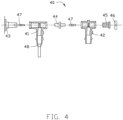
- FIG. 4 shows a cable connector 40 according to an embodiment.
- the cable connector 40 includes a front joint 41, a rear joint 42, a sleeve interface 43, an intermediate joint 44, a plug head 45, a closing head cover 46, and two stud bolts 47.
- the front joint 41 and the rear joint 42 are substantially T-shaped for inserting the cable.
- the front joint 41 and the rear joint 42 are further provided with a stress cone 48 for fixing the cable.
- the sleeve interface 43 and the intermediate joint 44 are positioned at the ends of the front joint 41.
- the sleeve interface 43 and the intermediate joint 44 are connected by one of the stud bolts 47.
- the sleeve interface 43 passes through the fixing plate 30.
- the intermediate joint 44 and the plug head 45 are disposed at the two ends of the rear joint 42.
- the intermediate joint 44 and the plug head 45 are connected by the other stud bolt 47.
- the closing head cover 46 is sealed at an end of the plug head 45 away from the rear joint 42.
- the cable connector 40 allows for insertion of two bundles of cables, for example, one cable of the second cable 602 is inserted into the front joint 41, and one of the third cables 603 is inserted into the rear joint 42.
- the cable connector 40 can also include a lightning arrestor or lightning guide.
- the number of the optical unit connection boxes 50 is at least one, the same being fixed to the fixing plate 30. In the embodiment, the number of the optical unit connection boxes 50 is two, one of the optical unit connection boxes 50 being used as a backup.
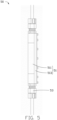
- FIG. 5 and FIG. 6 show an optical unit connection box 50 according to an embodiment.
- the optical unit connection box 50 includes a disk tray 51 and two fixing members 53 disposed at the two ends of the disk tray 51.
- the disk tray 51 includes a disk body 511 and a lid 513 that covers the disk body 511.
- the disk body 511 has a substantially elliptical cross section and defines a receiving space 515.
- the lid 513 is a substantially elliptical plate. The lid 513 is fixed to the disk body 511 to cover the receiving space 515.
- a fixing block 517 for positioning the optical fiber is positioned on the bottom of the disk 511.
- the fixing block 517 can receive and position the optical fiber by opening a receiving groove.
- the cable passes through the fixing member 53 at both ends of the disk tray 51 so that the optical fibers in the cable can be fused for onward signal transmission.
- the fixing member 53 includes a fixing head 531, two sleeves 533 connected to the fixing head 531, and two sealing members 535 positioned in the two sleeves 533.
- the fixing head 531 is fixed to the end of the disk body 511 and defines two fixing holes 5311.
- the fixing hole 5311 communicates with the receiving space 515. Two sleeves 533 are inserted into the two fixing holes 5311 of the fixing head 531 and fixed to the fixing head 531.
- each sleeve 533 defines a receiving groove.
- the sealing member 535 is annular and received in the receiving groove of the sleeve 533.
- the sleeve 533 allows the cable to pass through and is sealed by the sealing member 535.
- the fiber optic connector 60 is mounted on the cover 13 of the protecting case 10 and partially extends into the protecting case 10.
- the fiber optic connector 60 can be a connector in prior art for quickly connecting and unplugging the fiber connection.
- the electrical connector 70 is also mounted on the cover 13 of the protecting case 10 and partially extends into the protecting case 10 for access to the cable.
- the first cable 601, the second cable 602, and the third cable 603 all include electric cables and optical cables.
- the electric cable of the power generating platform 2 connects to the electrical connector 70 and enters the protecting case 10 to connect to the cable connector 40.
- the optical cable of the power generating platform 2 connects to the optical fiber connector 60 and the optical unit connecting box 50.
- the second cable 602 and the third cable 603 pass through the through hole 231 of the anchoring device 20 to enter the protecting case 10.
- the electrical cable of the second cable 602 and the electrical cable of the third cable 603 are connected to either the front joint 41 or the rear joint 42.
- the number of electrical cables of the second cable 602 and the third cable 603 are in bundles of six.
- the two bundles are connected with either a front joint 41 or a rear joint 42 of the cable connector 40.
- the power generation platform 2 has three electrical cables, respectively connected to the three cable connectors 40, so that the electrical cables of the power generation platform 2 are electrically connected to the electrical cables of the second cable 602 and the third cable 603.
- the optical cable of the second cable 602 and the optical cable of the third cable 603 are connected to the optical unit connection box 50.
- the optical cable of the first cable 601 is fused in the disk reel 51 to ensure signal transmission between the power generation platform 2 and other power generation platforms 2 and the base station 3.
- the optical cable of the second cable 602 and the optical cable of the third cable 603 may be connected by an optical cable connected between the optical fiber connector 60 and the optical unit connection box 50 instead of being directly connected to the optical cable of the first cable 601. At this time, the optical cable, the second cable 602, and the third cable 603 are fused in the disk tray 51.
- the offshore power generation system realizes connection of the one or more power generation platforms through the cable and the junction box to form a chain or mesh power generation system.
- the anchoring device, the cable connector, the optical unit connection box, the fiber connector, and the electrical connector ensure high structural and sealing performance of the cables in the junction box.
- the junction box of the disclosure satisfies the safety load 5T limit working condition 10T by a tensile test, and has no obvious displacement or slippage after being loaded for 5 minutes at the load of 20T. After 1 MPa of pressure held for 24 hours a watertightness test was carried out on the junction box, and no leakage occurred. A pressure test of 3.5 U0 (about 26 kV 5 min) was also passed.
Landscapes
- Physics & Mathematics (AREA)
- Engineering & Computer Science (AREA)
- Power Engineering (AREA)
- General Physics & Mathematics (AREA)
- Optics & Photonics (AREA)
- Light Guides In General And Applications Therefor (AREA)
Description
- The subject matter herein generally relates to electrical junction boxes, especially relates to a junction box suitable for use in marine engineering and an offshore power generation system using the junction box.
- Offshore oil and gas, wave energy, and dynamic platforms have become widespread. Offshore power generation platforms which are mobile play an important role in the future use of new energy sources, such as wave power generation which uses offshore tidal energy to generate electricity. Long-term operations at sea and in an ocean environment may be problematic for junction boxes to establish reliable connections for cables at sea. Prior art junction boxes include the ones disclosed in
US2003/021556A1 andEP2393220A1 . - In order to solve the above technical problems, the present disclosure provides an electronic junction box having high connection reliability and an offshore power generation system using the electronic junction box. A junction box according to the invention is defined in
independent claim 1. Preferred embodiments are defined in dependent claims 2-8. - A junction box comprising: a protecting case; an anchoring device; a cable connector; an optical unit connection box; an optical fiber connector; and an electrical connector; wherein each of the cable connector and the optical unit connection box is received in the protecting case, each of the anchoring device, the optical fiber connector and the electrical connector is mounted on the protecting case.
- In one embodiment, the protecting case comprises a main body and a cover fixed to an end of the main body, the anchoring device is fixed at an end of the main body away from the cover, the cable connector and the optical unit connection box are received in the main body, and the optical fiber connector and the electrical connector are mounted on the cover.
- According to the invention, the anchoring device comprises a fixing member and two wire passing members connected to the fixing member, the fixing member defines a line channel, each of the two wire passing members defines a wire passing hole.
- According to the invention, the fixing member comprises a positioning portion, a protrusion protruding from one end of the positioning portion, and a connecting portion connected to the other end of the positioning portion, the line channel penetrates the positioning portion, the protrusion and the connecting portion.
- In one embodiment, the junction box further comprises a fixing plate, the fixing plate is received in the protecting case and is fixed to the cover, the cable connector and the optical unit connection box are mounted on the fixing plate.
- In one embodiment, the cable connector comprises a front joint, a rear joint, a sleeve interface, an intermediate joint, a plug head, and a closing head cover, the sleeve interface and the intermediate joint are respectively positioned at both ends of the front joint, the sleeve interface and the intermediate joint are connected by a stud bolt, the intermediate joint and the plug head are respectively disposed at two ends of the rear joint, the intermediate joint and the plug head are connected by the other stud bolt, the closing head cover is sealed at an end of the plug head away from the rear joint.
- In one embodiment, the optical unit connection box comprises a disk tray and two fixing members respectively disposed at two ends of the disk tray, the disk tray comprises a disk body and a lid that is covered on the disk body, the fixing member is configured to fix cables, and the disk tray is configured to receive optical fibers.
- In one embodiment, the fixing member comprises a fixing head, two sleeves connected to the fixing head, and two sealing members positioned in the two sleeves, the fixing head is fixed to the disk body.
In one embodiment, A offshore power generation system comprising: at least one power generation platform; and above junction box; wherein optical cables of the power generating platform are connected to the optical fiber connector of the junction box, and electronic cables of the power generating platform are connected to the electrical connector, and the cable connector is connected to the electronic cables entering from the anchoring device, and the optical unit connection box is connected the optical cables entering from the anchoring device. - In one embodiment, the power generation platform is a wave energy generator.
- The offshore power generation system realizes connection of the one or more power generation platforms through the cable and the junction box to form a chain or mesh power generation system. The anchoring device, the cable connector, the optical unit connection box, the fiber connector, and the electrical connector, ensure high structural and sealing performance of the cables in the junction box.
- Implementations of the present technology will now be described, by way of embodiments with reference to the attached figures.
-
FIG. 1 is a schematic view of an offshore power generation system according to an embodiment. -
FIG. 2 is an isometric view of a junction box according to an embodiment in the system ofFIG. 1 . -
FIG. 3 is an isometric view of a part of the junction box inFIG. 2 . -
FIG. 4 is an exploded cross-sectional view of a cable connector according to an embodiment in the junction box. -
FIG. 5 is a lateral view of an optical unit connection box according to an embodiment in the junction box. -
FIG. 6 is a cross-sectional view of a part of the optical unit connection box inFIG. 5 . - It will be appreciated that for simplicity and clarity of illustration, where appropriate, reference numerals have been repeated among the different figures to indicate corresponding or analogous elements. In addition, numerous specific details are set forth in order to provide a thorough understanding of the embodiments described herein. However, it will be understood by those of ordinary skill in the art that the embodiments described herein can be practiced without these specific details. In other instances, methods, procedures, and components have not been described in detail so as not to obscure the related relevant feature being described. drawings are not necessarily to scale, and the proportions of certain parts may be exaggerated to show details and features of the present disclosure better. The disclosure is by way of embodiments and not by way of limitation in the figures of the accompanying drawings, in which like references indicate similar elements. It should be noted that references to "an" or "one" embodiment in this disclosure are not necessarily to the same embodiment, and such references mean "at least one."
- Several definitions that apply throughout this disclosure will now be presented.
- The term "substantially" is defined to be essentially conforming to the particular dimension, shape, or other feature that the term modifies, such that the component need not be exact. For example, "substantially cylindrical" means that the object resembles a cylinder, but can have one or more deviations from a true cylinder. The term "comprising," when utilized, means "including, but not necessarily limited to"; it specifically indicates open-ended inclusion or membership in the so-described combination, group, series, and the like. The references "a plurality of" and "a number of" mean "at least two."
-
FIG. 1 is a schematic view of an offshorepower generation system 1 according to an embodiment. The offshorepower generation system 1 includes at least onepower generation platform 2 positioned at sea, abase station 3 positioned on the land, afixing device 4 positioned at the seabed, at least onejunction box 5, and a plurality ofcables 6. Thebase station 3 includes a substation. Thepower generation platform 2 is configured to generate power using marine resources, such as wave energy. Thebase station 3 is configured to change the voltage of the power generated by thepower generation platform 2 to deliver the power onwardly. In the embodiment, the number of thepower generating platforms 2 shown inFIG. 1 is two. In other embodiments, the number of thepower generating platforms 2 can be one, or three or more, correspondingly, the number of thejunction boxes 5 can be one, or two or more. InFIG. 1 , the number of thejunction boxes 5 is also two. For convenience of description and understanding, the plurality ofcables 6 is defined to include afirst cable 601, asecond cable 602, athird cable 603, and afourth cable 604. Thefirst cable 601 is connected thepower generation platform 2 withcorresponding junction box 5. Thesecond cable 602 is a dynamic cable connected between twojunction boxes 5. Thethird cable 603 is a dynamic cable connecting one of thejunction boxes 5 and thefourth cable 604. Thefourth cable 604 is a static cable connecting thethird cable 603 with thebase station 3. In the embodiment, thethird cable 603 and thefourth cable 604 are connected by a joint 401, and the joint 401 is positioned on thefixing device 4. Thefixing device 4 is fixed to the seabed for positioning the junction of thethird cable 603 and thefourth cable 604. In the embodiment, the offshorepower generation system 1 is a wave power generation system, and accordingly, thepower generation platform 2 is a wave energy generator. Thefirst cable 601 is a cable of the generator. The offshorepower generation system 1 is not limited to being the wave power generation system, it can be other power generation system that generates power by other means. In the embodiment, the offshorepower generation system 1 connects the power generation platforms 2 (i.e., the two generators) in series to form a chain or mesh power generation system. - The offshore
power generation system 1 further includes at least onelifting device 7. The at least onelifting device 7 is connected to apower generating platform 2 for moving the offshorepower generation system 1. The at least onelifting device 7 can be connected to a body of a generator. Eachjunction box 5 is mounted on one of thelifting devices 7. In the embodiment, thejunction box 5 is fixed to one side of thelifting device 7 by a fixingframe 8, and thejunction box 5 and thelifting device 7 are beside each other. - Referring to
FIGS. 2 and3 , thejunction box 5 includes a protectingcase 10, ananchoring device 20, a fixingplate 30, acable connector 40, an opticalunit connection box 50, anoptical fiber connector 60, and anelectrical connector 70. The protectingcase 10 is hollow and accommodates the fixingplate 30, thecable connector 40, and the opticalunit connection box 50. The anchoringdevice 20 is mounted at an end of theprotection casing 10 for fixing cables (such as thesecond cable 602 and the third cable 603). The fixingplate 30 is fixedly positioned in the protectingcase 10 for positioning thecable connector 40 and the opticalunit connection box 50. Thecable connector 40 is fixed to the fixingplate 30 and received in the protectingcase 10. Thecable connector 40 is a plug-in terminal connector inside thejunction box 5 for ensuring power collection, connection, and grounded shielding between the dynamic cable and thepower generation platform 2. - The optical
unit connection box 50 is fixed to the fixingplate 30 and received in theprotective case 10 for ensuring communication between the twopower generation platforms 2, thepower generation platform 2, and thebase station 3. Theoptical fiber connector 60 is mounted on the protectingcase 10, and a part of theoptical fiber connector 60 passes through the protectingcase 10 to be received in the protectingcase 10. Thefiber optic connector 60 is an internal communication fiber optic plug connector of thepower generation platform 2, and is used for ensuring communication between internal signals of the power generation platform and external control signals. Theelectrical connector 70 is mounted on the protectingcase 10 for ensuring the connection between the internal power of thepower generating platform 2 and the junction box. Each component is specifically described. - In the embodiment, the protecting
case 10 is a substantially hollow cylinder. The protectingcase 10 includes amain body 11 and acover 13 fixed to an end of themain body 11. Themain body 11 is a hollow cylinder which is open at both ends. Thecover 13 is a circular plate shape. Thecover 13 covers the end of themain body 11. Thecover 13 defines areserved hole 131 for infilling with glue or oil when needed. The anchoringdevice 20 is fixed to the other end of themain body 11 and covers the other end of themain body 11. Specifically, the anchoringdevice 20 includes a fixingmember 21 and twowire passing members 23 connected to the fixingmember 21. The fixingmember 21 is substantially disk-shaped and is fixed to the other end of themain body 11. The fixingmember 21 includes apositioning portion 211, aprotrusion 213 protruding from one end of thepositioning portion 211, and a connectingportion 215 connected to the other end of thepositioning portion 211. In the embodiment, thepositioning portion 211, theprotrusion 213, and the connectingportion 215 have an integral structure. Thepositioning portion 211 is a substantially cylindrical, and theprotrusion 213 extends out of the peripheral edge of the end of thepositioning portion 211. The connectingportion 215 extends from the other end of thepositioning portion 211 along a longitudinal axis. Theprotrusion 213 is substantially disc shaped. The connectingportion 215 is substantially conical in shape. The fixingmember 21 defines aline channel 217 that penetrates thepositioning portion 211, theprotrusion 213, and the connectingportion 215. Theline channel 217 includes afirst channel 2171 extending through thepositioning portion 211 and theprotrusion 213 and twosecond channels 2173 extending through theconnection portion 215. The twosecond channels 2173 communicate with thefirst channel 2171 to form an inverted Y-shaped channel. A diameter of thefirst channel 2171 is larger than a diameter of thesecond channel 2173. Theline channel 217 allows passage for the cables. - The two
wire passing members 23 are fixed on the connectingportion 215 of the fixingmember 21 and correspond to the twosecond passages 2173. Eachwire passing member 23 defines awire passing hole 231, and eachwire passing hole 231 communicates with the correspondingsecond channel 2173. In the embodiment, two bundles of cables (such as thesecond cable 602 and the third cable 603) pass through the throughhole 231 and enter the twosecond channels 2173 to meet in thefirst channel 2171 and enter the protectingcase 10. The cable is fixed and sealed by the anchoringdevice 20. In other embodiments, the shape of the protectingcase 10 is not limited to one shape and may be, for example, a rectangular parallelepiped, a cube, an irregular shape, or the like. In other embodiments, the shape of theanchoring device 20 is not limited, provided that the cable can be fixed and sealed. - The fixing
plate 30 is connected to thecover 13 of the protectingcase 10 and received in the protectingcase 10 for positioning thecable connector 40 and the opticalunit connection box 50. In the embodiment, the fixingplate 30 is perpendicular to thecover 13 and offset from the center of the protectingcase 10. The number ofcable connectors 40 is three, eachcable connector 40 passes through the fixingplate 30 to be fixed to the fixingplate 30. Thecable connector 40 is configured to connect the cables. For example, after thesecond cable 602 and thethird cable 603 are passed through the anchoringdevice 20, the cable in thesecond cable 602 and the cable in thethird cable 603 are respectively inserted into thecorresponding cable connectors 40. In this embodiment, thesecond cable 602 includes three cables for insertion into threecable connectors 40. Thethird cable 603 includes three cables, and the three cables are inserted into threecable connectors 40. -
FIG. 4 shows acable connector 40 according to an embodiment. Thecable connector 40 includes a front joint 41, a rear joint 42, asleeve interface 43, an intermediate joint 44, aplug head 45, a closinghead cover 46, and twostud bolts 47. The front joint 41 and the rear joint 42 are substantially T-shaped for inserting the cable. The front joint 41 and the rear joint 42 are further provided with astress cone 48 for fixing the cable. Thesleeve interface 43 and the intermediate joint 44 are positioned at the ends of the front joint 41. Thesleeve interface 43 and the intermediate joint 44 are connected by one of thestud bolts 47. Thesleeve interface 43 passes through the fixingplate 30. The intermediate joint 44 and theplug head 45 are disposed at the two ends of the rear joint 42. The intermediate joint 44 and theplug head 45 are connected by theother stud bolt 47. The closinghead cover 46 is sealed at an end of theplug head 45 away from the rear joint 42. Thecable connector 40 allows for insertion of two bundles of cables, for example, one cable of thesecond cable 602 is inserted into the front joint 41, and one of thethird cables 603 is inserted into the rear joint 42. Thecable connector 40 can also include a lightning arrestor or lightning guide. - The number of the optical
unit connection boxes 50 is at least one, the same being fixed to the fixingplate 30. In the embodiment, the number of the opticalunit connection boxes 50 is two, one of the opticalunit connection boxes 50 being used as a backup.FIG. 5 andFIG. 6 show an opticalunit connection box 50 according to an embodiment. The opticalunit connection box 50 includes adisk tray 51 and two fixingmembers 53 disposed at the two ends of thedisk tray 51. Thedisk tray 51 includes adisk body 511 and alid 513 that covers thedisk body 511. In the embodiment, thedisk body 511 has a substantially elliptical cross section and defines a receivingspace 515. Thelid 513 is a substantially elliptical plate. Thelid 513 is fixed to thedisk body 511 to cover the receivingspace 515. A fixing block 517 for positioning the optical fiber is positioned on the bottom of thedisk 511. The fixing block 517 can receive and position the optical fiber by opening a receiving groove. The cable passes through the fixingmember 53 at both ends of thedisk tray 51 so that the optical fibers in the cable can be fused for onward signal transmission. The fixingmember 53 includes a fixing head 531, twosleeves 533 connected to the fixing head 531, and two sealing members 535 positioned in the twosleeves 533. The fixing head 531 is fixed to the end of thedisk body 511 and defines two fixingholes 5311. The fixinghole 5311 communicates with the receivingspace 515. Twosleeves 533 are inserted into the two fixingholes 5311 of the fixing head 531 and fixed to the fixing head 531. An inner wall of eachsleeve 533 defines a receiving groove. The sealing member 535 is annular and received in the receiving groove of thesleeve 533. Thesleeve 533 allows the cable to pass through and is sealed by the sealing member 535. - The
fiber optic connector 60 is mounted on thecover 13 of the protectingcase 10 and partially extends into the protectingcase 10. Thefiber optic connector 60 can be a connector in prior art for quickly connecting and unplugging the fiber connection. Theelectrical connector 70 is also mounted on thecover 13 of the protectingcase 10 and partially extends into the protectingcase 10 for access to the cable. - Taking the
junction box 5 which connects thefirst cable 601, thesecond cable 602, and thethird cable 603 inFIG. 1 as an example, thefirst cable 601, thesecond cable 602, and thethird cable 603 all include electric cables and optical cables. The electric cable of thepower generating platform 2 connects to theelectrical connector 70 and enters the protectingcase 10 to connect to thecable connector 40. The optical cable of thepower generating platform 2 connects to theoptical fiber connector 60 and the opticalunit connecting box 50. Thesecond cable 602 and thethird cable 603 pass through the throughhole 231 of theanchoring device 20 to enter the protectingcase 10. The electrical cable of thesecond cable 602 and the electrical cable of thethird cable 603 are connected to either the front joint 41 or the rear joint 42. In the embodiment, the number of electrical cables of thesecond cable 602 and thethird cable 603 are in bundles of six. The two bundles are connected with either a front joint 41 or a rear joint 42 of thecable connector 40. Correspondingly, thepower generation platform 2 has three electrical cables, respectively connected to the threecable connectors 40, so that the electrical cables of thepower generation platform 2 are electrically connected to the electrical cables of thesecond cable 602 and thethird cable 603. The optical cable of thesecond cable 602 and the optical cable of thethird cable 603 are connected to the opticalunit connection box 50. The optical cable of thefirst cable 601 is fused in thedisk reel 51 to ensure signal transmission between thepower generation platform 2 and otherpower generation platforms 2 and thebase station 3. In other embodiments, the optical cable of thesecond cable 602 and the optical cable of thethird cable 603 may be connected by an optical cable connected between theoptical fiber connector 60 and the opticalunit connection box 50 instead of being directly connected to the optical cable of thefirst cable 601. At this time, the optical cable, thesecond cable 602, and thethird cable 603 are fused in thedisk tray 51. - The offshore power generation system realizes connection of the one or more power generation platforms through the cable and the junction box to form a chain or mesh power generation system. The anchoring device, the cable connector, the optical unit connection box, the fiber connector, and the electrical connector, ensure high structural and sealing performance of the cables in the junction box. The junction box of the disclosure satisfies the safety load 5T limit working condition 10T by a tensile test, and has no obvious displacement or slippage after being loaded for 5 minutes at the load of 20T. After 1 MPa of pressure held for 24 hours a watertightness test was carried out on the junction box, and no leakage occurred. A pressure test of 3.5 U0 (about 26
kV 5 min) was also passed.
Claims (8)
- A junction box (5) comprising:a protecting case (10);an anchoring device (20);a plug-in terminal connector (40);an optical unit connection box (50);an optical fiber connector (60); andan electrical connector (70);wherein each of the plug-in terminal connector (40) and the optical unit connection box (50) is received in the protecting case (10), each of the anchoring device (20), the optical fiber connector (60) and the electrical connector (70) is mounted on the protecting case (10);wherein the anchoring device (20) comprises a fixing member (21) and two wire passing members (23) connected to the fixing member (21), the fixing member (21) defines a line channel (217), each of the two wire passing members (23) defines a wire passing holes (231);wherein the fixing member (21) comprises a positioning portion (211), a protrusion (213) protruding from one end of the positioning portion (211), and a connecting portion (215) connected to the other end of the positioning portion (211), the line channel (217) penetrates the positioning portion (211), the protrusion (213) and the connecting portion (215);wherein the line channel (217) comprises a first channel (2171) extending through the positioning portion (211) and the protrusion (213), and two second channels (2173) extending through the connecting portion (215);wherein the two second channels (2173) communicate with the first channel (2171) to form an inverted Y-shaped channel, a diameter of the first channel (217 : being larger than a diameter of the second channel (2173), the line channel (217) allowing passage for the cables,wherein the two wire passing members (23) are fixed on the connecting portion (215) of the fixing member (21) and correspond to the two second channels (2173), such that each wire passing hole (231) communicates with the corresponding second channel (2173),wherein two bundles of cables can pass through the wire passing hole (231) and enter the two second channels (2173) to meet in the first channel (2171) and enter the protecting case (10) such that the cables are fixed and sealed by the anchoring device (20).
- The junction box (5) of claim 1, wherein the protecting case (10) comprises a main body (11) and a cover (13) fixed to an end of the main body (11), the anchoring device (20) is fixed at an end of the main body (11) away from the cover (13), the plug-in terminal connector (40) and the optical unit connection box (50) are received in the main body (11), and the optical fiber connector (60) and the electrical connector (70) are mounted on the cover (13).
- The junction box of claim 2, wherein the junction box (5) further comprises a fixing plate (30), the fixing plate (30) is received in the protecting case (10) and is fixed to the cover (13), the plug-in terminal connector (40) and the optical unit connection box (50) are mounted on the fixing plate (30).
- The junction box of claim 1 or claim 3, wherein the plug-in terminal connector (40) comprises a front joint (41), a rear joint (42), a sleeve interface (43), an intermediate joint (44), a plug head (45), and a closing head cover (46), the sleeve interface (43) and the intermediate joint (44) are respectively positioned at both ends of the front joint (41), the sleeve interface (43) and the intermediate joint (44) are connected by a stud bolt (47), the intermediate joint (44) and the plug head (45) are respectively disposed at two ends of the rear joint (42), the intermediate joint (44) and the plug head (45) are connected by the other stud bolt (47), the closing head cover (46) is sealed at an end of the plug head (45) away from the rear joint (42).
- The junction box of claim 1 or claim 3, wherein the optical unit connection box (50) comprises a disk tray (51) and two fixing members (53) respectively disposed at two ends of the disk tray (51), the disk tray (51) comprises a disk body (511) and a lid (513) that is covered on the disk body (511), the fixing member (53) is configured to fix cables, and the disk tray (51) is configured to receive optical fibers.
- The junction box of claim 5, wherein the fixing member (53) comprises a fixing head (531), two sleeves (533) connected to the fixing head (531), and two sealing members (535) positioned in the two sleeves (533), the fixing head (531) is fixed to the disk body (511).
- A offshore power generation system (1) comprising:at least one power generation platform (2); anda junction box (5) as claimed in any of the claims 1-6; anda first cable (601), a second cable (602) and a third cable (603), each comprising optical cables and electric cables, wherein the first cable (601) connects the power generating platform (2) to the junction box (5);wherein optical cables of the first cable (601) from the power generating platform (2) are connected to the optical fiber connector (60) of the junction box (5), and electronic cables of the first cable (601) form the power generating platform (2) are connected to the electrical connector (70), and the plug-in terminal connector (40) is connected to the electronic cables of the second cable (602) and the third cable (603) entering from the anchoring device (20), and the optical unit connection box (50) is connected the optical cables of the second cable (602) and the third cable (603) entering from the anchoring device (20).
- The offshore power generation system (1) of claim 7, wherein the power generation platform (2) is a wave energy generator.
Applications Claiming Priority (1)
| Application Number | Priority Date | Filing Date | Title |
|---|---|---|---|
| PCT/CN2017/082346 WO2018195890A1 (en) | 2017-04-28 | 2017-04-28 | Junction box and offshore power generation system using junction box |
Publications (3)
| Publication Number | Publication Date |
|---|---|
| EP3618210A1 EP3618210A1 (en) | 2020-03-04 |
| EP3618210A4 EP3618210A4 (en) | 2020-09-30 |
| EP3618210B1 true EP3618210B1 (en) | 2023-05-10 |
Family
ID=63917874
Family Applications (1)
| Application Number | Title | Priority Date | Filing Date |
|---|---|---|---|
| EP17907009.9A Active EP3618210B1 (en) | 2017-04-28 | 2017-04-28 | Junction box and offshore power generation system using junction box |
Country Status (2)
| Country | Link |
|---|---|
| EP (1) | EP3618210B1 (en) |
| WO (1) | WO2018195890A1 (en) |
Families Citing this family (2)
| Publication number | Priority date | Publication date | Assignee | Title |
|---|---|---|---|---|
| CN111679390B (en) * | 2020-07-15 | 2024-08-23 | 国网湖北省电力有限公司鄂州供电公司 | Intelligent optical fiber junction box |
| CN115437076B (en) * | 2022-09-01 | 2023-08-04 | 烽火通信科技股份有限公司 | An outdoor pre-connected box |
Citations (1)
| Publication number | Priority date | Publication date | Assignee | Title |
|---|---|---|---|---|
| EP2393220B1 (en) * | 2010-06-03 | 2015-07-08 | Alcatel Lucent | Undersea optical and electrical distribution apparatus |
Family Cites Families (11)
| Publication number | Priority date | Publication date | Assignee | Title |
|---|---|---|---|---|
| US3602873A (en) * | 1969-02-13 | 1971-08-31 | Exxon Production Research Co | Underwater electrical connection station |
| US6510270B1 (en) * | 2001-07-24 | 2003-01-21 | Ocean Design, Inc. | Sub-oceanic cable network system and method |
| DE102007030450A1 (en) * | 2007-06-29 | 2009-01-02 | Robert Bosch Gmbh | Terminal box for electrical machine i.e. electric motor, has intermediate piece detachably arranged on box by retaining unit and comprising screw thread in order to fasten cable to piece, so that cable is guided through opening |
| GB0809334D0 (en) * | 2008-05-22 | 2008-07-02 | Scotrenewables Marine Power Lt | Generating apparatus |
| CN101882777A (en) * | 2009-05-06 | 2010-11-10 | 戚郁芬 | A cable splice box capable of waterproofing trunk cables in different ways |
| CN101630826B (en) * | 2009-07-08 | 2011-08-24 | 宁波海缆研究院工程有限公司 | Photoelectric composite submarine cable platform anchoring device |
| CN102236128A (en) * | 2010-04-26 | 2011-11-09 | 佳律通信设备(上海)有限公司 | Optical fiber connector protection device |
| US8686289B2 (en) * | 2011-07-14 | 2014-04-01 | Channell Commercial Corporation | Sealing mechanism and method for drop cable splice enclosures |
| WO2013087948A1 (en) * | 2011-12-12 | 2013-06-20 | Fundacion Tecnalia Research & Innovation | System and method for interconnecting umbilicals for conveying energy, fluids and/or data in a marine environment |
| NO345785B1 (en) * | 2015-01-19 | 2021-08-09 | Vetco Gray Scandinavia As | Subsea umbilical termination assembly |
| CN205986063U (en) * | 2016-08-16 | 2017-02-22 | 中天海洋系统有限公司 | Extra large cable anchor of pre -assembling formula |
-
2017
- 2017-04-28 EP EP17907009.9A patent/EP3618210B1/en active Active
- 2017-04-28 WO PCT/CN2017/082346 patent/WO2018195890A1/en not_active Ceased
Patent Citations (1)
| Publication number | Priority date | Publication date | Assignee | Title |
|---|---|---|---|---|
| EP2393220B1 (en) * | 2010-06-03 | 2015-07-08 | Alcatel Lucent | Undersea optical and electrical distribution apparatus |
Also Published As
| Publication number | Publication date |
|---|---|
| EP3618210A4 (en) | 2020-09-30 |
| EP3618210A1 (en) | 2020-03-04 |
| WO2018195890A1 (en) | 2018-11-01 |
Similar Documents
| Publication | Publication Date | Title |
|---|---|---|
| EP2745156B1 (en) | Subsea electro-optical connector unit for electro-optical ethernet transmission system | |
| US10393976B2 (en) | Device for distributing hybrid cable and transitioning from trunk cable to jumper cable with overvoltage protection | |
| Painter et al. | Current and future wet-mate connector technology developments for scientific seabed observatory applications | |
| CN108646365A (en) | A kind of sea floor optoelectronic composite cable deep-sea terminal separation device | |
| US4662002A (en) | Optical repeaters | |
| JPS60170338A (en) | Digital repeater | |
| CN207096519U (en) | Submarine optical fiber cable terminal separation device | |
| CN110932220B (en) | A submarine photoelectric separation equipment | |
| Rémouit et al. | Review of electrical connectors for underwater applications | |
| TWI792261B (en) | Interface, method and system for connecting electrical elements | |
| EP3618210A1 (en) | Junction box and offshore power generation system using junction box | |
| CN108808615B (en) | Junction box and offshore power generation system using same | |
| US9933580B2 (en) | Optical fiber penetration | |
| CN105093451A (en) | Fiber division and distribution device and communication site | |
| CN201984192U (en) | Composite optical cable connector box | |
| CN204116662U (en) | A kind of antivibration ejector half cable splice closure | |
| CN208399752U (en) | A kind of multi-functional sea cable submarine terminal photodetachment device | |
| CN113820812B (en) | Sea and land cable connecting equipment | |
| KR20120125821A (en) | Hybrid fanout cable | |
| CN110299643B (en) | Outdoor waterproof joint box | |
| CN204855902U (en) | Divide fibre and distribution device and communication station point | |
| Zhang et al. | A double-node star network coastal ocean observatory | |
| CN221995068U (en) | An underwater junction box | |
| CN218383378U (en) | OPGW optical cable fiber-splitting connection box with built-in plug interface | |
| KR102395601B1 (en) | Waterproof assembly for electric cable |
Legal Events
| Date | Code | Title | Description |
|---|---|---|---|
| STAA | Information on the status of an ep patent application or granted ep patent |
Free format text: STATUS: THE INTERNATIONAL PUBLICATION HAS BEEN MADE |
|
| PUAI | Public reference made under article 153(3) epc to a published international application that has entered the european phase |
Free format text: ORIGINAL CODE: 0009012 |
|
| STAA | Information on the status of an ep patent application or granted ep patent |
Free format text: STATUS: REQUEST FOR EXAMINATION WAS MADE |
|
| 17P | Request for examination filed |
Effective date: 20190731 |
|
| AK | Designated contracting states |
Kind code of ref document: A1 Designated state(s): AL AT BE BG CH CY CZ DE DK EE ES FI FR GB GR HR HU IE IS IT LI LT LU LV MC MK MT NL NO PL PT RO RS SE SI SK SM TR |
|
| AX | Request for extension of the european patent |
Extension state: BA ME |
|
| DAV | Request for validation of the european patent (deleted) | ||
| DAX | Request for extension of the european patent (deleted) | ||
| A4 | Supplementary search report drawn up and despatched |
Effective date: 20200827 |
|
| RIC1 | Information provided on ipc code assigned before grant |
Ipc: H02G 9/00 20060101AFI20200821BHEP Ipc: H02G 15/10 20060101ALI20200821BHEP Ipc: H02G 15/14 20060101ALI20200821BHEP Ipc: H02G 9/12 20060101ALI20200821BHEP Ipc: G02B 6/44 20060101ALI20200821BHEP Ipc: H02G 15/08 20060101ALI20200821BHEP Ipc: H02G 15/16 20060101ALI20200821BHEP Ipc: H01R 13/523 20060101ALI20200821BHEP Ipc: H02G 1/10 20060101ALI20200821BHEP |
|
| STAA | Information on the status of an ep patent application or granted ep patent |
Free format text: STATUS: EXAMINATION IS IN PROGRESS |
|
| 17Q | First examination report despatched |
Effective date: 20210224 |
|
| GRAP | Despatch of communication of intention to grant a patent |
Free format text: ORIGINAL CODE: EPIDOSNIGR1 |
|
| STAA | Information on the status of an ep patent application or granted ep patent |
Free format text: STATUS: GRANT OF PATENT IS INTENDED |
|
| INTG | Intention to grant announced |
Effective date: 20230201 |
|
| GRAS | Grant fee paid |
Free format text: ORIGINAL CODE: EPIDOSNIGR3 |
|
| GRAA | (expected) grant |
Free format text: ORIGINAL CODE: 0009210 |
|
| STAA | Information on the status of an ep patent application or granted ep patent |
Free format text: STATUS: THE PATENT HAS BEEN GRANTED |
|
| AK | Designated contracting states |
Kind code of ref document: B1 Designated state(s): AL AT BE BG CH CY CZ DE DK EE ES FI FR GB GR HR HU IE IS IT LI LT LU LV MC MK MT NL NO PL PT RO RS SE SI SK SM TR |
|
| REG | Reference to a national code |
Ref country code: GB Ref legal event code: FG4D |
|
| REG | Reference to a national code |
Ref country code: AT Ref legal event code: REF Ref document number: 1567681 Country of ref document: AT Kind code of ref document: T Effective date: 20230515 Ref country code: CH Ref legal event code: EP |
|
| REG | Reference to a national code |
Ref country code: DE Ref legal event code: R096 Ref document number: 602017068766 Country of ref document: DE |
|
| REG | Reference to a national code |
Ref country code: IE Ref legal event code: FG4D |
|
| REG | Reference to a national code |
Ref country code: LT Ref legal event code: MG9D |
|
| REG | Reference to a national code |
Ref country code: NL Ref legal event code: MP Effective date: 20230510 |
|
| REG | Reference to a national code |
Ref country code: AT Ref legal event code: MK05 Ref document number: 1567681 Country of ref document: AT Kind code of ref document: T Effective date: 20230510 |
|
| PG25 | Lapsed in a contracting state [announced via postgrant information from national office to epo] |
Ref country code: SE Free format text: LAPSE BECAUSE OF FAILURE TO SUBMIT A TRANSLATION OF THE DESCRIPTION OR TO PAY THE FEE WITHIN THE PRESCRIBED TIME-LIMIT Effective date: 20230510 Ref country code: PT Free format text: LAPSE BECAUSE OF FAILURE TO SUBMIT A TRANSLATION OF THE DESCRIPTION OR TO PAY THE FEE WITHIN THE PRESCRIBED TIME-LIMIT Effective date: 20230911 Ref country code: NO Free format text: LAPSE BECAUSE OF FAILURE TO SUBMIT A TRANSLATION OF THE DESCRIPTION OR TO PAY THE FEE WITHIN THE PRESCRIBED TIME-LIMIT Effective date: 20230810 Ref country code: NL Free format text: LAPSE BECAUSE OF FAILURE TO SUBMIT A TRANSLATION OF THE DESCRIPTION OR TO PAY THE FEE WITHIN THE PRESCRIBED TIME-LIMIT Effective date: 20230510 Ref country code: ES Free format text: LAPSE BECAUSE OF FAILURE TO SUBMIT A TRANSLATION OF THE DESCRIPTION OR TO PAY THE FEE WITHIN THE PRESCRIBED TIME-LIMIT Effective date: 20230510 Ref country code: AT Free format text: LAPSE BECAUSE OF FAILURE TO SUBMIT A TRANSLATION OF THE DESCRIPTION OR TO PAY THE FEE WITHIN THE PRESCRIBED TIME-LIMIT Effective date: 20230510 |
|
| PG25 | Lapsed in a contracting state [announced via postgrant information from national office to epo] |
Ref country code: RS Free format text: LAPSE BECAUSE OF FAILURE TO SUBMIT A TRANSLATION OF THE DESCRIPTION OR TO PAY THE FEE WITHIN THE PRESCRIBED TIME-LIMIT Effective date: 20230510 Ref country code: PL Free format text: LAPSE BECAUSE OF FAILURE TO SUBMIT A TRANSLATION OF THE DESCRIPTION OR TO PAY THE FEE WITHIN THE PRESCRIBED TIME-LIMIT Effective date: 20230510 Ref country code: LV Free format text: LAPSE BECAUSE OF FAILURE TO SUBMIT A TRANSLATION OF THE DESCRIPTION OR TO PAY THE FEE WITHIN THE PRESCRIBED TIME-LIMIT Effective date: 20230510 Ref country code: LT Free format text: LAPSE BECAUSE OF FAILURE TO SUBMIT A TRANSLATION OF THE DESCRIPTION OR TO PAY THE FEE WITHIN THE PRESCRIBED TIME-LIMIT Effective date: 20230510 Ref country code: IS Free format text: LAPSE BECAUSE OF FAILURE TO SUBMIT A TRANSLATION OF THE DESCRIPTION OR TO PAY THE FEE WITHIN THE PRESCRIBED TIME-LIMIT Effective date: 20230910 Ref country code: HR Free format text: LAPSE BECAUSE OF FAILURE TO SUBMIT A TRANSLATION OF THE DESCRIPTION OR TO PAY THE FEE WITHIN THE PRESCRIBED TIME-LIMIT Effective date: 20230510 Ref country code: GR Free format text: LAPSE BECAUSE OF FAILURE TO SUBMIT A TRANSLATION OF THE DESCRIPTION OR TO PAY THE FEE WITHIN THE PRESCRIBED TIME-LIMIT Effective date: 20230811 |
|
| PG25 | Lapsed in a contracting state [announced via postgrant information from national office to epo] |
Ref country code: FI Free format text: LAPSE BECAUSE OF FAILURE TO SUBMIT A TRANSLATION OF THE DESCRIPTION OR TO PAY THE FEE WITHIN THE PRESCRIBED TIME-LIMIT Effective date: 20230510 |
|
| PG25 | Lapsed in a contracting state [announced via postgrant information from national office to epo] |
Ref country code: SK Free format text: LAPSE BECAUSE OF FAILURE TO SUBMIT A TRANSLATION OF THE DESCRIPTION OR TO PAY THE FEE WITHIN THE PRESCRIBED TIME-LIMIT Effective date: 20230510 |
|
| PG25 | Lapsed in a contracting state [announced via postgrant information from national office to epo] |
Ref country code: SM Free format text: LAPSE BECAUSE OF FAILURE TO SUBMIT A TRANSLATION OF THE DESCRIPTION OR TO PAY THE FEE WITHIN THE PRESCRIBED TIME-LIMIT Effective date: 20230510 Ref country code: SK Free format text: LAPSE BECAUSE OF FAILURE TO SUBMIT A TRANSLATION OF THE DESCRIPTION OR TO PAY THE FEE WITHIN THE PRESCRIBED TIME-LIMIT Effective date: 20230510 Ref country code: RO Free format text: LAPSE BECAUSE OF FAILURE TO SUBMIT A TRANSLATION OF THE DESCRIPTION OR TO PAY THE FEE WITHIN THE PRESCRIBED TIME-LIMIT Effective date: 20230510 Ref country code: EE Free format text: LAPSE BECAUSE OF FAILURE TO SUBMIT A TRANSLATION OF THE DESCRIPTION OR TO PAY THE FEE WITHIN THE PRESCRIBED TIME-LIMIT Effective date: 20230510 Ref country code: DK Free format text: LAPSE BECAUSE OF FAILURE TO SUBMIT A TRANSLATION OF THE DESCRIPTION OR TO PAY THE FEE WITHIN THE PRESCRIBED TIME-LIMIT Effective date: 20230510 Ref country code: CZ Free format text: LAPSE BECAUSE OF FAILURE TO SUBMIT A TRANSLATION OF THE DESCRIPTION OR TO PAY THE FEE WITHIN THE PRESCRIBED TIME-LIMIT Effective date: 20230510 |
|
| REG | Reference to a national code |
Ref country code: DE Ref legal event code: R097 Ref document number: 602017068766 Country of ref document: DE |
|
| PLBE | No opposition filed within time limit |
Free format text: ORIGINAL CODE: 0009261 |
|
| STAA | Information on the status of an ep patent application or granted ep patent |
Free format text: STATUS: NO OPPOSITION FILED WITHIN TIME LIMIT |
|
| 26N | No opposition filed |
Effective date: 20240213 |
|
| PG25 | Lapsed in a contracting state [announced via postgrant information from national office to epo] |
Ref country code: SI Free format text: LAPSE BECAUSE OF FAILURE TO SUBMIT A TRANSLATION OF THE DESCRIPTION OR TO PAY THE FEE WITHIN THE PRESCRIBED TIME-LIMIT Effective date: 20230510 |
|
| PG25 | Lapsed in a contracting state [announced via postgrant information from national office to epo] |
Ref country code: SI Free format text: LAPSE BECAUSE OF FAILURE TO SUBMIT A TRANSLATION OF THE DESCRIPTION OR TO PAY THE FEE WITHIN THE PRESCRIBED TIME-LIMIT Effective date: 20230510 Ref country code: IT Free format text: LAPSE BECAUSE OF FAILURE TO SUBMIT A TRANSLATION OF THE DESCRIPTION OR TO PAY THE FEE WITHIN THE PRESCRIBED TIME-LIMIT Effective date: 20230510 |
|
| REG | Reference to a national code |
Ref country code: DE Ref legal event code: R119 Ref document number: 602017068766 Country of ref document: DE |
|
| PG25 | Lapsed in a contracting state [announced via postgrant information from national office to epo] |
Ref country code: BG Free format text: LAPSE BECAUSE OF FAILURE TO SUBMIT A TRANSLATION OF THE DESCRIPTION OR TO PAY THE FEE WITHIN THE PRESCRIBED TIME-LIMIT Effective date: 20230510 |
|
| PG25 | Lapsed in a contracting state [announced via postgrant information from national office to epo] |
Ref country code: MC Free format text: LAPSE BECAUSE OF FAILURE TO SUBMIT A TRANSLATION OF THE DESCRIPTION OR TO PAY THE FEE WITHIN THE PRESCRIBED TIME-LIMIT Effective date: 20230510 |
|
| PG25 | Lapsed in a contracting state [announced via postgrant information from national office to epo] |
Ref country code: MC Free format text: LAPSE BECAUSE OF FAILURE TO SUBMIT A TRANSLATION OF THE DESCRIPTION OR TO PAY THE FEE WITHIN THE PRESCRIBED TIME-LIMIT Effective date: 20230510 Ref country code: BG Free format text: LAPSE BECAUSE OF FAILURE TO SUBMIT A TRANSLATION OF THE DESCRIPTION OR TO PAY THE FEE WITHIN THE PRESCRIBED TIME-LIMIT Effective date: 20230510 |
|
| REG | Reference to a national code |
Ref country code: CH Ref legal event code: PL |
|
| PG25 | Lapsed in a contracting state [announced via postgrant information from national office to epo] |
Ref country code: LU Free format text: LAPSE BECAUSE OF NON-PAYMENT OF DUE FEES Effective date: 20240428 |
|
| REG | Reference to a national code |
Ref country code: BE Ref legal event code: MM Effective date: 20240430 |
|
| PG25 | Lapsed in a contracting state [announced via postgrant information from national office to epo] |
Ref country code: LU Free format text: LAPSE BECAUSE OF NON-PAYMENT OF DUE FEES Effective date: 20240428 |
|
| PG25 | Lapsed in a contracting state [announced via postgrant information from national office to epo] |
Ref country code: DE Free format text: LAPSE BECAUSE OF NON-PAYMENT OF DUE FEES Effective date: 20241105 |
|
| PG25 | Lapsed in a contracting state [announced via postgrant information from national office to epo] |
Ref country code: BE Free format text: LAPSE BECAUSE OF NON-PAYMENT OF DUE FEES Effective date: 20240430 |
|
| PG25 | Lapsed in a contracting state [announced via postgrant information from national office to epo] |
Ref country code: FR Free format text: LAPSE BECAUSE OF NON-PAYMENT OF DUE FEES Effective date: 20240430 |
|
| PG25 | Lapsed in a contracting state [announced via postgrant information from national office to epo] |
Ref country code: FR Free format text: LAPSE BECAUSE OF NON-PAYMENT OF DUE FEES Effective date: 20240430 Ref country code: DE Free format text: LAPSE BECAUSE OF NON-PAYMENT OF DUE FEES Effective date: 20241105 Ref country code: BE Free format text: LAPSE BECAUSE OF NON-PAYMENT OF DUE FEES Effective date: 20240430 Ref country code: CH Free format text: LAPSE BECAUSE OF NON-PAYMENT OF DUE FEES Effective date: 20240430 |
|
| PG25 | Lapsed in a contracting state [announced via postgrant information from national office to epo] |
Ref country code: IE Free format text: LAPSE BECAUSE OF NON-PAYMENT OF DUE FEES Effective date: 20240428 |
|
| PG25 | Lapsed in a contracting state [announced via postgrant information from national office to epo] |
Ref country code: CY Free format text: LAPSE BECAUSE OF FAILURE TO SUBMIT A TRANSLATION OF THE DESCRIPTION OR TO PAY THE FEE WITHIN THE PRESCRIBED TIME-LIMIT; INVALID AB INITIO Effective date: 20170428 |
|
| PG25 | Lapsed in a contracting state [announced via postgrant information from national office to epo] |
Ref country code: HU Free format text: LAPSE BECAUSE OF FAILURE TO SUBMIT A TRANSLATION OF THE DESCRIPTION OR TO PAY THE FEE WITHIN THE PRESCRIBED TIME-LIMIT; INVALID AB INITIO Effective date: 20170428 |
|
| PGFP | Annual fee paid to national office [announced via postgrant information from national office to epo] |
Ref country code: GB Payment date: 20260330 Year of fee payment: 10 |
|
| PG25 | Lapsed in a contracting state [announced via postgrant information from national office to epo] |
Ref country code: TR Free format text: LAPSE BECAUSE OF FAILURE TO SUBMIT A TRANSLATION OF THE DESCRIPTION OR TO PAY THE FEE WITHIN THE PRESCRIBED TIME-LIMIT Effective date: 20230510 |