EP3618160A1 - Cell and electrochemical device - Google Patents
Cell and electrochemical device Download PDFInfo
- Publication number
- EP3618160A1 EP3618160A1 EP19193676.4A EP19193676A EP3618160A1 EP 3618160 A1 EP3618160 A1 EP 3618160A1 EP 19193676 A EP19193676 A EP 19193676A EP 3618160 A1 EP3618160 A1 EP 3618160A1
- Authority
- EP
- European Patent Office
- Prior art keywords
- thickness
- cell
- diaphragm
- electrode
- adhesive
- Prior art date
- Legal status (The legal status is an assumption and is not a legal conclusion. Google has not performed a legal analysis and makes no representation as to the accuracy of the status listed.)
- Granted
Links
Images




Classifications
-
- H—ELECTRICITY
- H01—ELECTRIC ELEMENTS
- H01M—PROCESSES OR MEANS, e.g. BATTERIES, FOR THE DIRECT CONVERSION OF CHEMICAL ENERGY INTO ELECTRICAL ENERGY
- H01M10/00—Secondary cells; Manufacture thereof
- H01M10/04—Construction or manufacture in general
- H01M10/0431—Cells with wound or folded electrodes
-
- H—ELECTRICITY
- H01—ELECTRIC ELEMENTS
- H01M—PROCESSES OR MEANS, e.g. BATTERIES, FOR THE DIRECT CONVERSION OF CHEMICAL ENERGY INTO ELECTRICAL ENERGY
- H01M10/00—Secondary cells; Manufacture thereof
- H01M10/05—Accumulators with non-aqueous electrolyte
- H01M10/058—Construction or manufacture
- H01M10/0587—Construction or manufacture of accumulators having only wound construction elements, i.e. wound positive electrodes, wound negative electrodes and wound separators
-
- H—ELECTRICITY
- H01—ELECTRIC ELEMENTS
- H01M—PROCESSES OR MEANS, e.g. BATTERIES, FOR THE DIRECT CONVERSION OF CHEMICAL ENERGY INTO ELECTRICAL ENERGY
- H01M50/00—Constructional details or processes of manufacture of the non-active parts of electrochemical cells other than fuel cells, e.g. hybrid cells
- H01M50/40—Separators; Membranes; Diaphragms; Spacing elements inside cells
- H01M50/46—Separators, membranes or diaphragms characterised by their combination with electrodes
- H01M50/461—Separators, membranes or diaphragms characterised by their combination with electrodes with adhesive layers between electrodes and separators
-
- H—ELECTRICITY
- H01—ELECTRIC ELEMENTS
- H01M—PROCESSES OR MEANS, e.g. BATTERIES, FOR THE DIRECT CONVERSION OF CHEMICAL ENERGY INTO ELECTRICAL ENERGY
- H01M50/00—Constructional details or processes of manufacture of the non-active parts of electrochemical cells other than fuel cells, e.g. hybrid cells
- H01M50/50—Current conducting connections for cells or batteries
- H01M50/531—Electrode connections inside a battery casing
- H01M50/533—Electrode connections inside a battery casing characterised by the shape of the leads or tabs
-
- Y—GENERAL TAGGING OF NEW TECHNOLOGICAL DEVELOPMENTS; GENERAL TAGGING OF CROSS-SECTIONAL TECHNOLOGIES SPANNING OVER SEVERAL SECTIONS OF THE IPC; TECHNICAL SUBJECTS COVERED BY FORMER USPC CROSS-REFERENCE ART COLLECTIONS [XRACs] AND DIGESTS
- Y02—TECHNOLOGIES OR APPLICATIONS FOR MITIGATION OR ADAPTATION AGAINST CLIMATE CHANGE
- Y02E—REDUCTION OF GREENHOUSE GAS [GHG] EMISSIONS, RELATED TO ENERGY GENERATION, TRANSMISSION OR DISTRIBUTION
- Y02E60/00—Enabling technologies; Technologies with a potential or indirect contribution to GHG emissions mitigation
- Y02E60/10—Energy storage using batteries
-
- Y—GENERAL TAGGING OF NEW TECHNOLOGICAL DEVELOPMENTS; GENERAL TAGGING OF CROSS-SECTIONAL TECHNOLOGIES SPANNING OVER SEVERAL SECTIONS OF THE IPC; TECHNICAL SUBJECTS COVERED BY FORMER USPC CROSS-REFERENCE ART COLLECTIONS [XRACs] AND DIGESTS
- Y02—TECHNOLOGIES OR APPLICATIONS FOR MITIGATION OR ADAPTATION AGAINST CLIMATE CHANGE
- Y02P—CLIMATE CHANGE MITIGATION TECHNOLOGIES IN THE PRODUCTION OR PROCESSING OF GOODS
- Y02P70/00—Climate change mitigation technologies in the production process for final industrial or consumer products
- Y02P70/50—Manufacturing or production processes characterised by the final manufactured product
Definitions
- the present application relates to a field of batteries, more particularly to a cell and an electrochemical device having the cell.
- lithium-ion batteries have developed rapidly in applications such as electronic products and electrically powered tools due to their high cell energy density, customizable design, safety and reliability. As market demand expands, the lithium-ion batteries will have a development trend towards higher energy density, high power, and quick charge/discharge performance.
- a wound cell has an asymmetric structure in its thickness direction, and there are several areas where a cathode diaphragm and an anode diaphragm is missing, resulting in the uneven thickness of the cell.
- these areas are prone to risks of poor interface contact, serious polarization during charging and discharging processes, and a rapid decline in retention rate after a long cycle.
- an objective of the present application is to propose a cell whose thickness is more uniform, which can improve flatness of the cell, thereby improving energy density of the cell.
- the present application further proposes an electrochemical device.
- the cell according to the present application includes: a first electrode sheet, a first electrode tab, a second electrode sheet and a second electrode tab.
- the first electrode sheet includes a first current collector and a first active material layer.
- the first current collector includes a first end portion, and two sides of the first end portion are provided with the first active material layer.
- the first electrode tab is electrically connected with the first current collector.
- the second electrode sheet includes a second current collector and a second active material layer, the second active material layer is located on a surface of the second current collector.
- the second electrode tab is electrically connected with the second current collector.
- the first end portion has a width being one third of a width of the first electrode tab, and in a first direction, the cell has a thickness t at the first end portion, while the cell has a thickness T at the first electrode tab or the second electrode tab, t being greater than or equal to 95% of T.
- the thickness of the cell can be made more uniform, and the flatness of the cell can be improved, thereby increasing the energy density of the cell, so as to reduce a risk of cycle failure caused by insufficient pressure and loose interface contact at the corners of the cell at the time of fixture formation thereof.
- the second current collector includes a first abutting segment adjacent to the first end portion, and in the first direction, the first abutting segment does not overlap with the first end portion.
- the cell In the first direction, the cell has a thickness ta at the first abutting segment, and an absolute value of a difference between ta and T is smaller than or equal to 150 ⁇ m.
- the cell further includes a first bending section, in which the first abutting segment is located between the first bending section and the first end portion, and an absolute value of a difference between t and T is smaller than or equal to 50 ⁇ m.
- the cell further includes a separator located between the first electrode sheet and the second electrode sheet.
- the second electrode sheet is further provided with a first diaphragm adhesive.
- the thickness t at the first end portion is composed of a thickness t1 of a plurality of layers of the first electrode sheets, a thickness t2 of a plurality of layers of the second electrode sheets, a thickness t3 of a plurality of layers of the separators, and a thickness t4 of a plurality of layers of the first diaphragm adhesive.
- the first electrode sheet includes a first diaphragm, and the first diaphragm is provided to a head and a tail of the first active material layer.
- the second electrode sheet includes a second diaphragm, and the second diaphragm is provided to a head and a tail of the second active material layer, the first diaphragm adhesive being provided on the second diaphragm.
- the first diaphragm adhesive at a head of the second electrode sheet has a thickness of 25 to 100 ⁇ m and a width of 8 to 16 mm.
- the first diaphragm adhesive at a tail of the second electrode sheet has a thickness of 25 to 100 ⁇ m and a width of 12 to 20 mm.
- the first diaphragm adhesive is an adhesive tape with a gradient change in thickness.
- the first diaphragm adhesive includes a first thickness segment and a second thickness segment, and the first thickness segment has a thickness smaller than the second thickness segment.
- the first thickness segment has a thickness of 10 to 16 ⁇ m, while the second thickness segment has a thickness of 25 to 100 ⁇ m.
- the first electrode tab or the second electrode tab is provided with a first protective adhesive.
- the thickness T at the first electrode tab or the second electrode tab is composed of the thickness t1 of the plurality of layers of the first electrode sheets, the thickness t2 of the plurality of layers of the second electrode sheets, the thickness t3 of the plurality of layers of the separators, a thickness t5 of the first electrode tab or the second electrode tab, and a thickness t6 of the first protective adhesive.
- the first protective adhesive is provided to two sides of the first electrode tab or two sides of the second electrode tab.
- the thickness ta at the first abutting segment is composed of the thickness t1 of the plurality of layers of the first electrode sheets, the thickness t2 of the plurality of layers of the second electrode sheets, and the thickness t4 of the plurality of layers of the first diaphragm adhesive, the first diaphragm and the second diaphragm being located within the first abutting segment.
- the second electrode sheet further includes a second protective adhesive configured to protect a cutting position, the second protective adhesive is provided to the second current collector, and the second protective adhesive has a thickness of 25 to 100 ⁇ m and a width of 8 to 16 mm.
- the electrochemical device includes the above cell.
- the beneficial effects of the present application at least lie in that the flatness of the cell and hence the energy density thereof can be improved, so as to reduce the risk of cycle failure caused by insufficient pressure and loose interface contact at the corners of the cell at the time of fixture formation thereof.
- the reason for the above beneficial effects is that if the cell is uneven in structure, it is easy to cause contact with the thickest position (i.e., a position corresponding to a positive electrode tab or a negative electrode tab) of the cell firstly when it is compressed into a clamping plate in a fixture formation process, such that the pressure at the position is maximized.
- the corner area is insufficiently pressed or even is not pressed due to thinness, which is not conducive to the formation of a compact SEI (Solid Electrolyte Interphase) film with excellent performance. Additionally, due to the loose contact among the layers at the corners, the interface contact during the long-circulation process is deteriorated, resulting in large polarization at this point, which is easy to form a black spotted lithium interface, and eventually leads to cycle failure.
- SEI Solid Electrolyte Interphase
- a cell 10 according to embodiments of the present application will be described with reference to Figs. 1-12 .
- the cell 10 includes a first electrode sheet 1, a first electrode tab 2, a second electrode sheet 3 and a second electrode tab 4. It should be noted that if the first electrode sheet 1 is an anode electrode sheet, the second electrode sheet 3 is a cathode electrode sheet, and if the second electrode sheet 3 is an anode electrode sheet, the first electrode sheet 1 is a cathode electrode sheet.
- the first electrode sheet 1 is adopted as the anode electrode sheet by way of example in the present application.
- the first electrode sheet 1 can include a first current collector 11 and a first active material layer 12, the first current collector 11 can include a first end portion 111, and two sides of the first end portion 111 are provided with the first active material layer 12 separately.
- the first electrode tab 2 is electrically connected with the first current collector 11.
- the second electrode sheet 3 can include a second current collector 31 and a second active material layer 32, and the second active material layer 32 is located on a surface of the second current collector 31.
- the second electrode tab 4 is electrically connected with the second current collector 31.
- the first end portion 111 can have a width being one third of a width of the first electrode tab 2.
- a thickness of the cell 10 at the first end portion 111 is denoted as t
- a thickness of the cell 10 at the first electrode tab 2 or the second electrode tab 4 is denoted as T, in which t ⁇ 95%T.
- the first direction refers to an up-and-down direction in Fig. 1 .
- the thickness of the cell 10 can become more uniform, and the flatness of the cell 10 can be improved, so that the energy density of the cell 10 can be improved, thereby reducing a risk of cycle failure caused by insufficient pressure and loose interface contact at corners of the cell 10 at the time of fixture formation thereof. Meanwhile, it is also possible to reduce the manufacturing difficulty of the cell 10, improve the production efficiency of the cell 10, and lower the manufacturing cost of the cell 10.
- the thickness of the cell 10 can be made more uniform, and the flatness of the cell 10 can be improved, thereby increasing the energy density of the cell 10, so as to reduce the risk of cycle failure caused by insufficient pressure and loose interface contact at the corners of the cell 10 at the time of fixture formation thereof.
- the second current collector 31 can include a first abutting segment 311 adjacent to the first end portion 111, and in the first direction, the first abutting segment 311 does not overlap with the first end portion 111 (the term "adjacent to" in the present application means a distance between the first abutting segment 311 and the first end portion 111 is less than 1 mm in a left-and-right direction on the premise that the first abutting segment 311 and the first end portion 111 do not overlap in the up-and-down direction), that is, in the up-and-down direction, the first abutting segment 311 does not overlap with the first end portion 111, such that the thickness of the cell 10 can be made more uniform, and the flatness of the cell 1 0 can be further improved.
- the cell 10 can further include a first bending section 5.
- the first abutting segment 311 is located between the first bending section 5 and the first end portion 111, and an absolute value of a difference between the thickness at the first end portion 111 and the thickness at the first electrode tab 2 or the second electrode tab 4 is smaller than or equal to 50 ⁇ m, i.e.,
- the first end portion 111 and the first abutting segment 311 of the cell 10 with a wound structure in odd numbered layers are located at the same side; a corner region is defined between a tail diaphragm of the first electrode sheet 1 and the first bending section 5, while the remaining region is a region of a tail green tape corresponds to the diaphragm of the first electrode sheet 1.
- the first end portions 111 and the first abutting segments 311 at the head and tail of the cell 10 with a wound structure in even numbered layers are located at the opposite sides.
- the cell 10 can further include a separator 6 isolated between the first electrode sheet 1 and the second electrode sheet 3, and the separator 6 can serve as a barrier to space the first electrode sheet 1 apart from the second electrode sheet 3, thereby preventing a short circuit from occurring inside the cell 10, so as to ensure the safety of use of the cell 10.
- the first electrode sheet 1 can include a first diaphragm, and the first diaphragm may be disposed at the head and the tail of the first active material layer 12;
- the second electrode sheet 3 can include a second diaphragm, and the second diaphragm may be disposed at the head and the tail of the second active material layer 32;
- a first diaphragm adhesive 33 may be provided on the second diaphragm.
- the thickness of the first diaphragm adhesive 33 on the second diaphragm By adjusting the thickness of the first diaphragm adhesive 33 on the second diaphragm, or lengthening a diaphragm length of the active material layer (increasing the amount of the active material), or combining the above two manners, it is possible to compensate the thickness of the cell 10 at a position corresponding to the first bending section 5, and control a difference between the thickness at the first electrode tab 2 or the second electrode tab 4 and the thickness of the cell 10 at the corners, so as to better improve the flatness of the cell 10, thereby reducing the risk of cycle failure caused by insufficient pressure and loose interface contact at the corners of the cell 10 at the time of fixture formation thereof.
- the first diaphragm adhesive 33 at the head of the second electrode sheet 3 has a thickness of 25 to 100 ⁇ m, and this first diaphragm adhesive 33 has a width of 8 to 16 mm. It should be noted that a width direction of the first diaphragm adhesive 33 refers to the left-and-right direction in Fig. 1 . Thus, such an arrangement can make the size of the first diaphragm adhesive 33 at the head of the second electrode sheet 3 more reasonable, and the thickness of the cell 1 0 can be made more uniform.
- the first diaphragm adhesive 33 at the tail of the second electrode sheet 3 can have a thickness of 25 to 100 ⁇ m, and this first diaphragm adhesive 33 can have a width of 12 to 20 mm.
- the thickness of the first diaphragm adhesive 33 at the head of the second electrode sheet 3 and the first diaphragm adhesive 33 at the tail of the second electrode sheet 3 can be adjusted alternatively or simultaneously according to actual design requirements.
- the thickness missing at the first abutting segment 311 and the first end portion 111 of the cell 10 due to the first diaphragm and the second diaphragm can be compensated, such that the difference between the thickness at the corner of the cell 10 and the thickness at the first electrode tab 2 or the second electrode tab 4 of the cell 10 can be reduced, or the thickness at the corner of the cell 10 can be consistence with the thickness at the first electrode tab 2 or the second electrode tab 4 of the cell 10.
- the pressure at the corner of the cell 10 is increased to promote formation of a good SEI (Solid Electrolyte Interphase) film, and the first diaphragm adhesive 33 having an increased thickness fills a gap between the electrode sheets to make the interface contact tighter, and the good interface contact during the long cycle can in turn reduce the risk of cycle failure.
- SEI Solid Electrolyte Interphase
- the first diaphragm adhesive 33 can be an adhesive tape with a gradient change in thickness, in which the gradient change of the thickness of the adhesive tape can improve a phenomenon that a thickness of an overlapping region between the first diaphragm adhesive 33 and the diaphragm may be enlarged after thickness increase.
- the first diaphragm adhesive 33 can include a first thickness segment 331 and a second thickness segment 332.
- the first thickness segment 331 has a thickness smaller than the second thickness segment 332, such that the first diaphragm adhesive 33 can have a more reasonable structure to ensure the gradient change of the thickness of the first diaphragm adhesive 33, thereby guaranteeing the working performance of the first diaphragm adhesive 33.
- the first thickness segment 331 can have a thickness of 10 to 16 ⁇ m, while the second thickness segment 332 can have a thickness of 25 to 100 ⁇ m, such that the first diaphragm adhesive 33 can have a more reasonable size design, and the structure of the first diaphragm adhesive 33 can be optimized, thereby promoting the working performance of the first diaphragm adhesive 33.
- the first electrode tab 2 or the second electrode tab 4 can be provided with a first protective adhesive 7, and the first protective adhesive 7 can act to protect the first electrode tab 2 and the second electrode tab 4, thereby preventing the first electrode tab 2 and the second electrode tab 4 from being damaged.
- the thickness at the first electrode tab 2 and the second electrode tab 4 takes a maximum value of a sum of the thickness at the first electrode tab 2 and the second electrode tab 4 and the thickness of the first protective adhesive 7.
- the first protective adhesive 7 can be provided to upper and lower sides of the first electrode tab 2 or upper and lower sides of the second electrode tab 4, so as to protect the first electrode tab 2 and the second electrode tab 4 better, thereby further preventing the first electrode tab 2 and the second electrode tab 4 from being damaged.
- a thickness ta at the first abutting segment 311 is composed of a thickness t1 of a plurality of layers of the first electrode sheets 1, a thickness t2 of a plurality of layers of the second electrode sheets 3, a thickness t3 of a plurality of layers of the separators 6, and a thickness t4 of a plurality of layers of the first diaphragm adhesives 33, in which the first diaphragm and the second diaphragm are located within the first abutting segment 311.
- the second electrode sheet 3 can further include a second protective adhesive used to protect a cutting position.
- the second protective adhesive can be provided to the second current collector 31, and can have a thickness of 25 to 100 ⁇ m and have a width of 8 to 16 mm.
- the second protective adhesive can have a more reasonable size design, and the structure of the second protective adhesive can be optimized, thereby improving the working performance of the second protective adhesive.
- the thickness t at the first end portion 111 ⁇ 95% of the thickness T at the first electrode tab 2 or the second electrode tab 4 + (1/N ⁇ the thickness T at the first electrode tab 2 or the second electrode tab 4 - 2 ⁇ the thickness ts of a single layer of the separator 6) ⁇ 1.08, in which N represents the number of layers of the cell 10.
- the thickness T at the first electrode tab 2 or the second electrode tab 4 the thickness T1 of the first electrode sheet 1 + a thickness T2 of the second electrode sheet 3 + a thickness T3 of the separator 6 + a thickness T4 of the green tape.
- the thickness of the first electrode sheet 1 is a total thickness of all the layers of the first current collector 11, the first active material layer 12 applied on the first current collector 11, and the first electrode tab 2 welded on the first current collector 11.
- the thickness of the second electrode sheet 3 is a total thickness of all the layers of the second current collector 31, the second active material layer 32 applied on the second current collector 31, and the second electrode tab 4 welded on the second current collector 31.
- the thickness of the separator 6 in the cell 10 is a total thickness of all the layers of the separator 6.
- the thickness of the green tape is a total thickness of the protective adhesive of the first protective adhesive 7 and the second protective adhesive.
- the maximum thickness lies at the first electrode tab 2 or the second electrode tab 4; a difference between the thickness at the first bending section 5 and the thickness at the electrode tab ranges from 300 to 540 ⁇ m; a difference between the thickness at the first end portion 111 and the thickness at the electrode tab ranges from 200 to 240 ⁇ m; a difference between the thickness at the first abutting segment 311 and the thickness at the electrode tab is less than 150 ⁇ m. Preferably, a difference between the thickness at the first end portion 111 and the thickness at the electrode tab is less than 50 ⁇ m.
- the maximum thickness lies at the first protective adhesive 7; a difference between the thickness at the first abutting segment 311 and the thickness at the electrode tab ranges from 280 to 530 ⁇ m; a difference between the thickness at the first end portion 111 and the thickness at the electrode tab ranges from 180 to 230 ⁇ m.
- the thickness of the first diaphragm adhesive 33 is increased, and the difference between the thickness at the first abutting segment 311 and the thickness at the electrode tab can be less than 150 ⁇ m.
- the diaphragm length of the first diaphragm tail of the first electrode sheet 1 can be extended to the first abutting segment 311 to compensate the thickness of this region.
- the diaphragm length of the second diaphragm tail of the second electrode sheet 3 can be extended to the first abutting segment 311 to compensate the thickness of this region.
- the wound structure is composed of the first electrode sheet 1, the separator 6 and the second electrode sheet 3.
- the first diaphragm adhesive 33 at the head of the second electrode sheet 3 is improved in terms of protection, and the thickness of the first diaphragm adhesive 33 is increased.
- the first electrode sheet 1 can include the first current collector 11, the first active material layer 12 applied on the first current collector 11, the first electrode tab 2 welded on the first current collector 11, the second protective adhesive, and the first protective adhesive 7.
- the second electrode sheet 3 can include the second current collector 31, the second active material layer 32 applied on the second current collector 31, the second electrode tab 4 welded on the second current collector 31, the second diaphragm, the first diaphragm adhesive 33, and the first protective adhesive 7.
- the wound structure can be realized in such a way that the separator 6 is fed, and a roll core clamps the separator 6 and rotates, so that the roll core and the separator 6 form an angle of about 30°; the first electrode sheet 1 enters the roll core with a feeding position determined by the position of the first electrode tab 2, after the electrode tab is welded and applied with an electrode tab adhesive and a protective adhesive; the roll core drives the first electrode sheet 1 and the separator 6 to rotate by half a turn; afterwards, the second electrode sheet 3 enters the roll core with a feeding position determined by the position of the second electrode tab 4, after the electrode tab is welded, and applied with an electrode tab adhesive; subsequently, the roll core rotates continuously until the winding is completed, and then is pulled out; as a result, a bare cell 10 with objective wound structure is obtained.
- a length of the first diaphragm of the first electrode sheet 1 is greater than a length of the second diaphragm of the second electrode sheet 3 by 3 to 5 mm; a distance between the first diaphragm and a corner arc is 0 to 0.5 mm; a length of the tail of the first diaphragm of the first electrode sheet 1 is greater than a length of the second diaphragm by 1 to 3 mm, and a distance between the first diaphragm and a corner arc is 1.5 to 3.5 mm.
- the first protective adhesive 7 and the second diaphragm overlap by 0.5 to 2 mm, and after the first diaphragm glue 33 passes through the arc, a tail end of the first diaphragm adhesive 33 should fall within the first end portion 111.
- the first diaphragm adhesive 33 may be a modified protective adhesive as illustrated in Figs. 3-5 , in which a thin end is 16 ⁇ m in thickness and 2 mm in width, while a thick end is designed to be 40 ⁇ m in thickness and 9 mm in width.
- the first diaphragm adhesive 33 on the tail of the second diaphragm can also be a modified protective adhesive as illustrated in Figs. 3-5 , in which a thin end is 16 ⁇ m in thickness and 2 mm in width, while a thick end is designed to be 40 ⁇ m in thickness and 13 mm in width.
- a difference between the thickness at the first abutting segment 311 and the thickness at the electrode tab the thickness of the first diaphragm adhesive 33 of the second diaphragm at the head of the four-layered second electrode sheet 3 + the thickness of the first diaphragm adhesive 33 of the second diaphragm at the tail of the four-layered second electrode sheet 3 - 2 ⁇ (the thickness of the second diaphragm - the thickness of the second current collector 31) - the thickness of the electrode tab - the thickness of two layers of the first protective adhesive 7 - the thickness of one layer of the first electrode sheet 1 in the first bending section 5 - a thickness difference of one layer of the first diaphragm in an overhang section and one layer of the first diaphragm in a non-overhang section + the thickness of two layers of the separator 6.
- a difference between the thickness at the first end portion 111 and the thickness at the electrode tab the thickness of the first diaphragm adhesive 33 of the second diaphragm at the head of the four-layered second electrode sheet 3 + the thickness of the first diaphragm adhesive 33 at the tail of the four-layered second electrode sheet 3 - 2 ⁇ (the thickness of the second diaphragm - the thickness of the second current collector 31) - the thickness of the electrode tab - the thickness of two layers of the first protective adhesive 7 - a thickness difference of two layers of the first diaphragm in the overhang section and two layers of the first diaphragm in the non-overhang section + the thickness of two layers of the separator 6.
- the thickness of the second diaphragm may be 118.5 ⁇ m
- the thickness of the second current collector 31 may be 10 ⁇ m
- the thickness of the electrode tab may be 80 ⁇ m
- the thickness of the first protective adhesive 7 may be 10 ⁇ m
- the thickness of the first electrode sheet 1 may be 151.4 ⁇ m
- the thickness difference of the first diaphragm in the overhang section and in the non-overhang section may be 16.5 ⁇ m
- the thickness of the separator 6 may be 10 ⁇ m
- the thickness of the first diaphragm adhesive 33 at both of the head and tail of the second electrode sheet 3 may be 16 ⁇ m in a conventional design
- the thickness difference between the first end portion 111 and the electrode tab is 337.1 ⁇ m
- the thickness difference between the first abutting segment 311 and the electrode tab is 202.2 ⁇ m.
- the thickness difference between the first end portion 111 and the electrode tab is 145.1 ⁇ m
- the thickness difference between the first abutting segment 311 and the electrode tab is 10.2 ⁇ m, such that the thickness difference can be reduced and controlled within 200 ⁇ m, thereby improving the flatness of the cell 10.
- the process of applying the first diaphragm adhesive 33 with an increased thickness is the same as the process of applying the first diaphragm adhesive 33 at the thin head, so the device does not need to be modified or upgraded, and the production efficiency will not be affected.
- the second protective adhesive is added to the structure of the cell 10, and the second protective adhesive is used to protect a cutting position. Moreover, the diaphragm length of the first diaphragm at the tail of the first electrode sheet 1 and the diaphragm length of the second diaphragm at the tail of the second electrode sheet 3 can be extended to the first abutting segment 311.
- the wound structure is composed of the first electrode sheet 1, the separator 6 and the second electrode sheet 3, and the thickness of the first diaphragm adhesive 33 of the second diaphragm at the head of the second electrode sheet 3 and the thickness of the first diaphragm adhesive 33 of the second diaphragm at the tail of the second electrode sheet 3 are both increased.
- the first electrode sheet 1 can include the first current collector 11, the first active material layer 12 applied on the first current collector 11, the first electrode tab 2 welded on the first current collector 11, the first protective adhesive 7, and the second protective adhesive.
- the first active material layer 12 is coated on both sides of the first current collector 11, in which one side is continuously coated, marked as a long side, and the other side is coated with intervals, marked as a short side.
- the short side needs to be provided with the second protective adhesive
- the second protective adhesive is a modified protective adhesive with a thin end of 10 ⁇ m thickness and 2 mm width, and a thick end of 40 ⁇ m thickness and 5 mm width.
- the second protective adhesive and the first diaphragm overlap by 0.5 to 2 mm.
- the second electrode sheet 3 can include the second current collector 31, the second active material layer 32 applied on the second current collector 31, the second electrode tab 4 welded on the second current collector 31, and the first diaphragm adhesive 33 and the first protective adhesive 7 on two opposite sides of the second diaphragm at the head and tail of the second electrode sheet 3.
- the first diaphragm at the head of the first electrode sheet 1 is longer than the second diaphragm of the second electrode sheet 3 by 3 to 5 mm; the distance between the first diaphragm at the head of the first electrode sheet 1 and the first bending section 5 is 0 to 0.5 mm; the first diaphragm at the tail of the first electrode sheet 1 corresponds to and is flush with the second diaphragm of the second electrode sheet 3, with a maximum value of misalignment being 1 mm; the first diaphragm at the tail of the first electrode sheet 1 and the second diaphragm at the tail of the second electrode sheet 3 need to exceed the first bending section by 50 ⁇ 1.0 mm; and the thickness of the first diaphragm adhesive 33 at the tail of the second electrode sheet 3 can be 16 ⁇ m.
- the first diaphragm adhesive 33 at the tail of the second electrode sheet 3 is to overlap the second diaphragm by 2.5 to 4 mm, and after the first diaphragm adhesive 33 at the head and tail of the second electrode sheet 3 passes through the first bending section 5, the tail end of the first diaphragm adhesive 33 should fall at the first end portion 111.
- the cell 1 0 has an increased thickness of the first diaphragm adhesive 33 at the head of the second electrode sheet 3.
- the cell 1 0 has an increased thickness of the first diaphragm adhesive 33 at the head of the second electrode sheet 3, and also an increased thickness of the first diaphragm adhesive 33 at the tail of the second electrode sheet 3; moreover, the first diaphragm at the tail of the first electrode sheet 1 is extended to the first abutting segment 311.
- the cell 10 is additionally provided with the second protective adhesive.
- the cell 10 is additionally provided with the second protective adhesive, and the cell 10 is also additionally provided with the first diaphragm adhesive 33 at the second diaphragm at the head of the second electrode sheet 3.
- the cell 10 is additionally provided with the second protective adhesive, and the cell 10 is also additionally provided with the first diaphragm adhesive 33 at the second diaphragm at the head of the second electrode sheet 3; moreover, the diaphragm length of the first diaphragm at the tail of the first electrode sheet 1 is extended to the first end portion 111.
- the first diaphragm at the tail of the first electrode sheet 1 is extended to the first abutting segment 311 to increase the thickness of the first abutting segment 311.
- the first diaphragm at the tail of the first electrode sheet 1 and the second diaphragm at the tail of the second electrode sheet 3 are both extended to the first abutting segment 311 to increase the thickness of the first abutting segment 311.
- the first diaphragm at the tail of the first electrode sheet 1 is extended to the first abutting segment 311 to increase the thickness of the first abutting segment 311, such that the flatness of the cell 10 can be further improved, and the energy density of the cell 10 can be further enhanced, thereby further reducing the risk of cycle failure caused by insufficient pressure and loose interface contact at the corners of the cell 10 at the time of fixture formation thereof.
- the flatness of the cell 10 can be further improved, and the energy density of the cell 10 can be further enhanced, thereby further reducing the risk of cycle failure caused by insufficient pressure and loose interface contact at the corners of the cell 10 at the time of fixture formation thereof.
- An electrochemical device includes the cell 10 in the above embodiments.
- the cell 10 is mounted to the electrochemical device, and with such a cell 10, the thickness of the cell 10 can be made more uniform to improve the flatness of the cell 10 and enhance the energy density of the cell 10, thereby further reducing the risk of cycle failure caused by insufficient pressure and loose interface contact at the corners of the cell 10 at the time of fixture formation thereof.
Landscapes
- Chemical & Material Sciences (AREA)
- Chemical Kinetics & Catalysis (AREA)
- Electrochemistry (AREA)
- General Chemical & Material Sciences (AREA)
- Engineering & Computer Science (AREA)
- Manufacturing & Machinery (AREA)
- Secondary Cells (AREA)
- Connection Of Batteries Or Terminals (AREA)
- Battery Electrode And Active Subsutance (AREA)
Abstract
Description
- The present application relates to a field of batteries, more particularly to a cell and an electrochemical device having the cell.
- In recent years, lithium-ion batteries have developed rapidly in applications such as electronic products and electrically powered tools due to their high cell energy density, customizable design, safety and reliability. As market demand expands, the lithium-ion batteries will have a development trend towards higher energy density, high power, and quick charge/discharge performance. However, a wound cell has an asymmetric structure in its thickness direction, and there are several areas where a cathode diaphragm and an anode diaphragm is missing, resulting in the uneven thickness of the cell. Especially in the design of a high energy density and quick charge system, these areas are prone to risks of poor interface contact, serious polarization during charging and discharging processes, and a rapid decline in retention rate after a long cycle.
- The present application aims to solve at least one of the technical problems existing in the related art. Accordingly, an objective of the present application is to propose a cell whose thickness is more uniform, which can improve flatness of the cell, thereby improving energy density of the cell. The present application further proposes an electrochemical device.
- The cell according to the present application includes: a first electrode sheet, a first electrode tab, a second electrode sheet and a second electrode tab. The first electrode sheet includes a first current collector and a first active material layer. The first current collector includes a first end portion, and two sides of the first end portion are provided with the first active material layer. The first electrode tab is electrically connected with the first current collector. The second electrode sheet includes a second current collector and a second active material layer, the second active material layer is located on a surface of the second current collector. The second electrode tab is electrically connected with the second current collector. The first end portion has a width being one third of a width of the first electrode tab, and in a first direction, the cell has a thickness t at the first end portion, while the cell has a thickness T at the first electrode tab or the second electrode tab, t being greater than or equal to 95% of T.
- According to the cell of the present application, through cooperation among the first electrode sheet, the first electrode tab, the second electrode sheet and the second electrode tab, the thickness of the cell can be made more uniform, and the flatness of the cell can be improved, thereby increasing the energy density of the cell, so as to reduce a risk of cycle failure caused by insufficient pressure and loose interface contact at the corners of the cell at the time of fixture formation thereof.
- In some examples of the present application, the second current collector includes a first abutting segment adjacent to the first end portion, and in the first direction, the first abutting segment does not overlap with the first end portion. In the first direction, the cell has a thickness ta at the first abutting segment, and an absolute value of a difference between ta and T is smaller than or equal to 150 µm.
- In some examples of the present application, the cell further includes a first bending section, in which the first abutting segment is located between the first bending section and the first end portion, and an absolute value of a difference between t and T is smaller than or equal to 50 µm.
- In some examples of the present application, the cell further includes a separator located between the first electrode sheet and the second electrode sheet. The second electrode sheet is further provided with a first diaphragm adhesive. The thickness t at the first end portion is composed of a thickness t1 of a plurality of layers of the first electrode sheets, a thickness t2 of a plurality of layers of the second electrode sheets, a thickness t3 of a plurality of layers of the separators, and a thickness t4 of a plurality of layers of the first diaphragm adhesive.
- In some examples of the present application, the first electrode sheet includes a first diaphragm, and the first diaphragm is provided to a head and a tail of the first active material layer. The second electrode sheet includes a second diaphragm, and the second diaphragm is provided to a head and a tail of the second active material layer, the first diaphragm adhesive being provided on the second diaphragm.
- In some examples of the present application, the first diaphragm adhesive at a head of the second electrode sheet has a thickness of 25 to 100 µm and a width of 8 to 16 mm.
- In some examples of the present application, the first diaphragm adhesive at a tail of the second electrode sheet has a thickness of 25 to 100 µm and a width of 12 to 20 mm.
- In some examples of the present application, the first diaphragm adhesive is an adhesive tape with a gradient change in thickness.
- In some examples of the present application, the first diaphragm adhesive includes a first thickness segment and a second thickness segment, and the first thickness segment has a thickness smaller than the second thickness segment.
- In some examples of the present application, the first thickness segment has a thickness of 10 to 16 µm, while the second thickness segment has a thickness of 25 to 100 µm.
- In some examples of the present application, the first electrode tab or the second electrode tab is provided with a first protective adhesive. The thickness T at the first electrode tab or the second electrode tab is composed of the thickness t1 of the plurality of layers of the first electrode sheets, the thickness t2 of the plurality of layers of the second electrode sheets, the thickness t3 of the plurality of layers of the separators, a thickness t5 of the first electrode tab or the second electrode tab, and a thickness t6 of the first protective adhesive.
- In some examples of the present application, the first protective adhesive is provided to two sides of the first electrode tab or two sides of the second electrode tab.
- In some examples of the present application, the thickness ta at the first abutting segment is composed of the thickness t1 of the plurality of layers of the first electrode sheets, the thickness t2 of the plurality of layers of the second electrode sheets, and the thickness t4 of the plurality of layers of the first diaphragm adhesive, the first diaphragm and the second diaphragm being located within the first abutting segment.
- In some examples of the present application, the second electrode sheet further includes a second protective adhesive configured to protect a cutting position, the second protective adhesive is provided to the second current collector, and the second protective adhesive has a thickness of 25 to 100 µm and a width of 8 to 16 mm.
- The electrochemical device includes the above cell.
- The beneficial effects of the present application at least lie in that the flatness of the cell and hence the energy density thereof can be improved, so as to reduce the risk of cycle failure caused by insufficient pressure and loose interface contact at the corners of the cell at the time of fixture formation thereof. The reason for the above beneficial effects is that if the cell is uneven in structure, it is easy to cause contact with the thickest position (i.e., a position corresponding to a positive electrode tab or a negative electrode tab) of the cell firstly when it is compressed into a clamping plate in a fixture formation process, such that the pressure at the position is maximized. Although the cell is deformed and contracted after being subjected to pressure, and the other region other than the positive and negative electrode tabs are subjected to an increased pressure, the corner area is insufficiently pressed or even is not pressed due to thinness, which is not conducive to the formation of a compact SEI (Solid Electrolyte Interphase) film with excellent performance. Additionally, due to the loose contact among the layers at the corners, the interface contact during the long-circulation process is deteriorated, resulting in large polarization at this point, which is easy to form a black spotted lithium interface, and eventually leads to cycle failure.
- These and other aspects and advantages of embodiments of the present application will become apparent and more readily appreciated from the following descriptions made with reference to the drawings, in which:
-
Fig. 1 is a partially enlarged view of a cell according to an embodiment of the present application. -
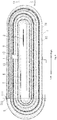
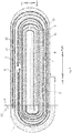
Fig. 2 is a schematic view of a cell according to a specific embodiment of the present application. -
Fig. 3 is a front view of a second protective adhesive of a cell according to an embodiment of the present application. -
Fig. 4 is a side view of a second protective adhesive of a cell according to an embodiment of the present application. -
Fig. 5 is a top view of a second protective adhesive of a cell according to an embodiment of the present application. -
Fig. 6 is a schematic view of a cell according to another specific embodiment of the present application. -
Fig. 7 is a schematic view of a cell according to another specific embodiment of the present application. -
Fig. 8 is a schematic view of a cell according to another specific embodiment of the present application. -
Fig. 9 is a schematic view of a cell according to another specific embodiment of the present application. -
Fig. 10 is a schematic view of a cell according to another specific embodiment of the present application. -
Fig. 11 is a schematic view of a cell according to another specific embodiment of the present application. -
Fig. 12 is a schematic view of a cell according to another specific embodiment of the present application. -
-
cell 10; -
first electrode sheet 1, firstcurrent collector 11,first end portion 111; - first
active material layer 12; -
first electrode tab 2; -
second electrode sheet 3, secondcurrent collector 31, first abuttingsegment 311; - second
active material layer 32; - first diaphragm adhesive 33,
first thickness segment 331,second thickness segment 332; -
second electrode tab 4,first bending section 5,separator 6, firstprotective adhesive 7. - Embodiments of the present application will be described in detail and examples of the embodiments will be illustrated in the drawings, where same or similar reference numerals are used to indicate same or similar elements or elements with same or similar functions. The embodiments described herein with reference to drawings are illustrative, and used to explain the present application. The embodiments shall not be construed to limit the present application.
- A
cell 10 according to embodiments of the present application will be described with reference toFigs. 1-12 . - As illustrated in
Figs. 1-12 , thecell 10 according to the embodiments of the present application includes afirst electrode sheet 1, afirst electrode tab 2, asecond electrode sheet 3 and asecond electrode tab 4. It should be noted that if thefirst electrode sheet 1 is an anode electrode sheet, thesecond electrode sheet 3 is a cathode electrode sheet, and if thesecond electrode sheet 3 is an anode electrode sheet, thefirst electrode sheet 1 is a cathode electrode sheet. - The
first electrode sheet 1 is adopted as the anode electrode sheet by way of example in the present application. Thefirst electrode sheet 1 can include a firstcurrent collector 11 and a firstactive material layer 12, the firstcurrent collector 11 can include afirst end portion 111, and two sides of thefirst end portion 111 are provided with the firstactive material layer 12 separately. Thefirst electrode tab 2 is electrically connected with the firstcurrent collector 11. Thesecond electrode sheet 3 can include a secondcurrent collector 31 and a secondactive material layer 32, and the secondactive material layer 32 is located on a surface of the secondcurrent collector 31. Thesecond electrode tab 4 is electrically connected with the secondcurrent collector 31. - The
first end portion 111 can have a width being one third of a width of thefirst electrode tab 2. In a first direction, a thickness of thecell 10 at thefirst end portion 111 is denoted as t, while a thickness of thecell 10 at thefirst electrode tab 2 or thesecond electrode tab 4 is denoted as T, in which t≥95%T. It should be noted that the first direction refers to an up-and-down direction inFig. 1 . - By configuring the width of the
cell 10 at thefirst end portion 111 to be one third of the width of thefirst electrode tab 2, and configuring the thickness of the cell at thefirst end portion 111 to be greater than or equal to the thickness of the cell at thefirst electrode tab 2 or thesecond electrode tab 4, the thickness of thecell 10 can become more uniform, and the flatness of thecell 10 can be improved, so that the energy density of thecell 10 can be improved, thereby reducing a risk of cycle failure caused by insufficient pressure and loose interface contact at corners of thecell 10 at the time of fixture formation thereof. Meanwhile, it is also possible to reduce the manufacturing difficulty of thecell 10, improve the production efficiency of thecell 10, and lower the manufacturing cost of thecell 10. - Thus, through cooperation among the
first electrode sheet 1, thefirst electrode tab 2, thesecond electrode sheet 3 and thesecond electrode tab 4, the thickness of thecell 10 can be made more uniform, and the flatness of thecell 10 can be improved, thereby increasing the energy density of thecell 10, so as to reduce the risk of cycle failure caused by insufficient pressure and loose interface contact at the corners of thecell 10 at the time of fixture formation thereof. - In some embodiments of the present application, as illustrated in
Fig. 1 , the secondcurrent collector 31 can include a firstabutting segment 311 adjacent to thefirst end portion 111, and in the first direction, the firstabutting segment 311 does not overlap with the first end portion 111 (the term "adjacent to" in the present application means a distance between the firstabutting segment 311 and thefirst end portion 111 is less than 1 mm in a left-and-right direction on the premise that the firstabutting segment 311 and thefirst end portion 111 do not overlap in the up-and-down direction), that is, in the up-and-down direction, the firstabutting segment 311 does not overlap with thefirst end portion 111, such that the thickness of thecell 10 can be made more uniform, and the flatness of thecell 1 0 can be further improved. - In some embodiments of the present application, as illustrated in
Fig. 1 , thecell 10 can further include afirst bending section 5. The firstabutting segment 311 is located between thefirst bending section 5 and thefirst end portion 111, and an absolute value of a difference between the thickness at thefirst end portion 111 and the thickness at thefirst electrode tab 2 or thesecond electrode tab 4 is smaller than or equal to 50 µm, i.e., | t-T | ≤50 µm, such that the thickness of thecell 10 can be made more reasonable, and the energy density of thecell 10 can be ensured. - Furthermore, as illustrated in
Fig. 1 , thefirst end portion 111 and the firstabutting segment 311 of thecell 10 with a wound structure in odd numbered layers are located at the same side; a corner region is defined between a tail diaphragm of thefirst electrode sheet 1 and thefirst bending section 5, while the remaining region is a region of a tail green tape corresponds to the diaphragm of thefirst electrode sheet 1. As illustrated inFig. 2 , thefirst end portions 111 and the first abuttingsegments 311 at the head and tail of thecell 10 with a wound structure in even numbered layers are located at the opposite sides. - In some embodiments of the present application, as illustrated in
Fig. 1 , thecell 10 can further include aseparator 6 isolated between thefirst electrode sheet 1 and thesecond electrode sheet 3, and theseparator 6 can serve as a barrier to space thefirst electrode sheet 1 apart from thesecond electrode sheet 3, thereby preventing a short circuit from occurring inside thecell 10, so as to ensure the safety of use of thecell 10. - In some embodiments of the present application, the
first electrode sheet 1 can include a first diaphragm, and the first diaphragm may be disposed at the head and the tail of the firstactive material layer 12; thesecond electrode sheet 3 can include a second diaphragm, and the second diaphragm may be disposed at the head and the tail of the secondactive material layer 32; afirst diaphragm adhesive 33 may be provided on the second diaphragm. - By adjusting the thickness of the
first diaphragm adhesive 33 on the second diaphragm, or lengthening a diaphragm length of the active material layer (increasing the amount of the active material), or combining the above two manners, it is possible to compensate the thickness of thecell 10 at a position corresponding to thefirst bending section 5, and control a difference between the thickness at thefirst electrode tab 2 or thesecond electrode tab 4 and the thickness of thecell 10 at the corners, so as to better improve the flatness of thecell 10, thereby reducing the risk of cycle failure caused by insufficient pressure and loose interface contact at the corners of thecell 10 at the time of fixture formation thereof. - In some embodiments of the present application, the first diaphragm adhesive 33 at the head of the
second electrode sheet 3 has a thickness of 25 to 100 µm, and thisfirst diaphragm adhesive 33 has a width of 8 to 16 mm. It should be noted that a width direction of thefirst diaphragm adhesive 33 refers to the left-and-right direction inFig. 1 . Thus, such an arrangement can make the size of the first diaphragm adhesive 33 at the head of thesecond electrode sheet 3 more reasonable, and the thickness of thecell 1 0 can be made more uniform. - In some embodiments of the present application, the first diaphragm adhesive 33 at the tail of the
second electrode sheet 3 can have a thickness of 25 to 100 µm, and this first diaphragm adhesive 33 can have a width of 12 to 20 mm. The thickness of the first diaphragm adhesive 33 at the head of thesecond electrode sheet 3 and the first diaphragm adhesive 33 at the tail of thesecond electrode sheet 3 can be adjusted alternatively or simultaneously according to actual design requirements. By adjusting the thickness of thefirst diaphragm adhesive 33, the thickness missing at the firstabutting segment 311 and thefirst end portion 111 of thecell 10 due to the first diaphragm and the second diaphragm can be compensated, such that the difference between the thickness at the corner of thecell 10 and the thickness at thefirst electrode tab 2 or thesecond electrode tab 4 of thecell 10 can be reduced, or the thickness at the corner of thecell 10 can be consistence with the thickness at thefirst electrode tab 2 or thesecond electrode tab 4 of thecell 10. At the time of fixture formation, the pressure at the corner of thecell 10 is increased to promote formation of a good SEI (Solid Electrolyte Interphase) film, and thefirst diaphragm adhesive 33 having an increased thickness fills a gap between the electrode sheets to make the interface contact tighter, and the good interface contact during the long cycle can in turn reduce the risk of cycle failure. - In some embodiments of the present application, as illustrated in
Figs. 3-5 , the first diaphragm adhesive 33 can be an adhesive tape with a gradient change in thickness, in which the gradient change of the thickness of the adhesive tape can improve a phenomenon that a thickness of an overlapping region between thefirst diaphragm adhesive 33 and the diaphragm may be enlarged after thickness increase. - In some embodiments of the present application, as illustrated in
Fig. 3 , the first diaphragm adhesive 33 can include afirst thickness segment 331 and asecond thickness segment 332. Thefirst thickness segment 331 has a thickness smaller than thesecond thickness segment 332, such that the first diaphragm adhesive 33 can have a more reasonable structure to ensure the gradient change of the thickness of thefirst diaphragm adhesive 33, thereby guaranteeing the working performance of thefirst diaphragm adhesive 33. - In some embodiments of the present application, the
first thickness segment 331 can have a thickness of 10 to 16 µm, while thesecond thickness segment 332 can have a thickness of 25 to 100 µm, such that the first diaphragm adhesive 33 can have a more reasonable size design, and the structure of the first diaphragm adhesive 33 can be optimized, thereby promoting the working performance of thefirst diaphragm adhesive 33. - In some embodiments of the present application, as illustrated in
Figs. 2 ,6 ,8 ,9 ,11 ,12 , 14 and 15, thefirst electrode tab 2 or thesecond electrode tab 4 can be provided with a firstprotective adhesive 7, and the firstprotective adhesive 7 can act to protect thefirst electrode tab 2 and thesecond electrode tab 4, thereby preventing thefirst electrode tab 2 and thesecond electrode tab 4 from being damaged. The thickness at thefirst electrode tab 2 and thesecond electrode tab 4 takes a maximum value of a sum of the thickness at thefirst electrode tab 2 and thesecond electrode tab 4 and the thickness of the firstprotective adhesive 7. - In some embodiments of the present application, as illustrated in
Figs. 2 ,6 ,8 ,9 ,11 ,12 , 14 and 15, the firstprotective adhesive 7 can be provided to upper and lower sides of thefirst electrode tab 2 or upper and lower sides of thesecond electrode tab 4, so as to protect thefirst electrode tab 2 and thesecond electrode tab 4 better, thereby further preventing thefirst electrode tab 2 and thesecond electrode tab 4 from being damaged. - In some embodiments of the present application, a thickness ta at the first
abutting segment 311 is composed of a thickness t1 of a plurality of layers of thefirst electrode sheets 1, a thickness t2 of a plurality of layers of thesecond electrode sheets 3, a thickness t3 of a plurality of layers of theseparators 6, and a thickness t4 of a plurality of layers of thefirst diaphragm adhesives 33, in which the first diaphragm and the second diaphragm are located within the firstabutting segment 311. - In some embodiments of the present application, the
second electrode sheet 3 can further include a second protective adhesive used to protect a cutting position. The second protective adhesive can be provided to the secondcurrent collector 31, and can have a thickness of 25 to 100 µm and have a width of 8 to 16 mm. As a result, the second protective adhesive can have a more reasonable size design, and the structure of the second protective adhesive can be optimized, thereby improving the working performance of the second protective adhesive. - Moreover, in a long cycle, the following relationships are satisfied, i.e., the thickness t at the
first end portion 111 ≥ 95% of the thickness T at thefirst electrode tab 2 or thesecond electrode tab 4 + (1/N × the thickness T at thefirst electrode tab 2 or the second electrode tab 4 - 2 × the thickness ts of a single layer of the separator 6) × 1.08, in which N represents the number of layers of thecell 10. The thickness T at thefirst electrode tab 2 or thesecond electrode tab 4 = the thickness T1 of thefirst electrode sheet 1 + a thickness T2 of thesecond electrode sheet 3 + a thickness T3 of theseparator 6 + a thickness T4 of the green tape. - The thickness of the
first electrode sheet 1 is a total thickness of all the layers of the firstcurrent collector 11, the firstactive material layer 12 applied on the firstcurrent collector 11, and thefirst electrode tab 2 welded on the firstcurrent collector 11. The thickness of thesecond electrode sheet 3 is a total thickness of all the layers of the secondcurrent collector 31, the secondactive material layer 32 applied on the secondcurrent collector 31, and thesecond electrode tab 4 welded on the secondcurrent collector 31. The thickness of theseparator 6 in thecell 10 is a total thickness of all the layers of theseparator 6. The thickness of the green tape is a total thickness of the protective adhesive of the firstprotective adhesive 7 and the second protective adhesive. - In some
cells 10, the maximum thickness lies at thefirst electrode tab 2 or thesecond electrode tab 4; a difference between the thickness at thefirst bending section 5 and the thickness at the electrode tab ranges from 300 to 540 µm; a difference between the thickness at thefirst end portion 111 and the thickness at the electrode tab ranges from 200 to 240 µm; a difference between the thickness at the firstabutting segment 311 and the thickness at the electrode tab is less than 150 µm. Preferably, a difference between the thickness at thefirst end portion 111 and the thickness at the electrode tab is less than 50 µm. - In some
other cells 10, the maximum thickness lies at the firstprotective adhesive 7; a difference between the thickness at the firstabutting segment 311 and the thickness at the electrode tab ranges from 280 to 530 µm; a difference between the thickness at thefirst end portion 111 and the thickness at the electrode tab ranges from 180 to 230 µm. By adding the second protective adhesive, the thickness of thefirst diaphragm adhesive 33 is increased, and the difference between the thickness at the firstabutting segment 311 and the thickness at the electrode tab can be less than 150 µm. - The diaphragm length of the first diaphragm tail of the
first electrode sheet 1 can be extended to the firstabutting segment 311 to compensate the thickness of this region. The diaphragm length of the second diaphragm tail of thesecond electrode sheet 3 can be extended to the firstabutting segment 311 to compensate the thickness of this region. - The
cell 10 according to the embodiments of the present application will be described in detail with reference to the drawings. - As illustrated in
Fig. 7 , according to a specific embodiment of the present application, the wound structure is composed of thefirst electrode sheet 1, theseparator 6 and thesecond electrode sheet 3. The first diaphragm adhesive 33 at the head of thesecond electrode sheet 3 is improved in terms of protection, and the thickness of thefirst diaphragm adhesive 33 is increased. In this embodiment, thefirst electrode sheet 1 can include the firstcurrent collector 11, the firstactive material layer 12 applied on the firstcurrent collector 11, thefirst electrode tab 2 welded on the firstcurrent collector 11, the second protective adhesive, and the firstprotective adhesive 7. Thesecond electrode sheet 3 can include the secondcurrent collector 31, the secondactive material layer 32 applied on the secondcurrent collector 31, thesecond electrode tab 4 welded on the secondcurrent collector 31, the second diaphragm, thefirst diaphragm adhesive 33, and the firstprotective adhesive 7. - In this embodiment, the wound structure can be realized in such a way that the
separator 6 is fed, and a roll core clamps theseparator 6 and rotates, so that the roll core and theseparator 6 form an angle of about 30°; thefirst electrode sheet 1 enters the roll core with a feeding position determined by the position of thefirst electrode tab 2, after the electrode tab is welded and applied with an electrode tab adhesive and a protective adhesive; the roll core drives thefirst electrode sheet 1 and theseparator 6 to rotate by half a turn; afterwards, thesecond electrode sheet 3 enters the roll core with a feeding position determined by the position of thesecond electrode tab 4, after the electrode tab is welded, and applied with an electrode tab adhesive; subsequently, the roll core rotates continuously until the winding is completed, and then is pulled out; as a result, abare cell 10 with objective wound structure is obtained. - In this embodiment, a length of the first diaphragm of the
first electrode sheet 1 is greater than a length of the second diaphragm of thesecond electrode sheet 3 by 3 to 5 mm; a distance between the first diaphragm and a corner arc is 0 to 0.5 mm; a length of the tail of the first diaphragm of thefirst electrode sheet 1 is greater than a length of the second diaphragm by 1 to 3 mm, and a distance between the first diaphragm and a corner arc is 1.5 to 3.5 mm. The firstprotective adhesive 7 and the second diaphragm overlap by 0.5 to 2 mm, and after thefirst diaphragm glue 33 passes through the arc, a tail end of the first diaphragm adhesive 33 should fall within thefirst end portion 111. Thefirst diaphragm adhesive 33 may be a modified protective adhesive as illustrated inFigs. 3-5 , in which a thin end is 16 µm in thickness and 2 mm in width, while a thick end is designed to be 40 µm in thickness and 9 mm in width. Thefirst diaphragm adhesive 33 on the tail of the second diaphragm can also be a modified protective adhesive as illustrated inFigs. 3-5 , in which a thin end is 16 µm in thickness and 2 mm in width, while a thick end is designed to be 40 µm in thickness and 13 mm in width. - In this embodiment, a difference between the thickness at the first
abutting segment 311 and the thickness at the electrode tab = the thickness of thefirst diaphragm adhesive 33 of the second diaphragm at the head of the four-layeredsecond electrode sheet 3 + the thickness of thefirst diaphragm adhesive 33 of the second diaphragm at the tail of the four-layered second electrode sheet 3 - 2∗(the thickness of the second diaphragm - the thickness of the second current collector 31) - the thickness of the electrode tab - the thickness of two layers of the first protective adhesive 7 - the thickness of one layer of thefirst electrode sheet 1 in the first bending section 5 - a thickness difference of one layer of the first diaphragm in an overhang section and one layer of the first diaphragm in a non-overhang section + the thickness of two layers of theseparator 6. - In this embodiment, a difference between the thickness at the
first end portion 111 and the thickness at the electrode tab = the thickness of thefirst diaphragm adhesive 33 of the second diaphragm at the head of the four-layeredsecond electrode sheet 3 + the thickness of the first diaphragm adhesive 33 at the tail of the four-layered second electrode sheet 3 - 2∗(the thickness of the second diaphragm - the thickness of the second current collector 31) - the thickness of the electrode tab - the thickness of two layers of the first protective adhesive 7 - a thickness difference of two layers of the first diaphragm in the overhang section and two layers of the first diaphragm in the non-overhang section + the thickness of two layers of theseparator 6. - In this embodiment, the thickness of the second diaphragm may be 118.5 µm, the thickness of the second
current collector 31 may be 10 µm, the thickness of the electrode tab may be 80 µm, the thickness of the firstprotective adhesive 7 may be 10 µm, the thickness of thefirst electrode sheet 1 may be 151.4 µm, the thickness difference of the first diaphragm in the overhang section and in the non-overhang section may be 16.5 µm, the thickness of theseparator 6 may be 10 µm, the thickness of the first diaphragm adhesive 33 at both of the head and tail of thesecond electrode sheet 3 may be 16 µm in a conventional design, the thickness difference between thefirst end portion 111 and the electrode tab is 337.1 µm, and the thickness difference between the firstabutting segment 311 and the electrode tab is 202.2 µm. When a 40 µm thick modified second protective adhesive is employed, the thickness difference between thefirst end portion 111 and the electrode tab is 145.1 µm, and the thickness difference between the firstabutting segment 311 and the electrode tab is 10.2 µm, such that the thickness difference can be reduced and controlled within 200 µm, thereby improving the flatness of thecell 10. Additionally, the process of applying the first diaphragm adhesive 33 with an increased thickness is the same as the process of applying the first diaphragm adhesive 33 at the thin head, so the device does not need to be modified or upgraded, and the production efficiency will not be affected. - As illustrated in
Fig. 10 , according to another specific embodiment of the present application, the second protective adhesive is added to the structure of thecell 10, and the second protective adhesive is used to protect a cutting position. Moreover, the diaphragm length of the first diaphragm at the tail of thefirst electrode sheet 1 and the diaphragm length of the second diaphragm at the tail of thesecond electrode sheet 3 can be extended to the firstabutting segment 311. The wound structure is composed of thefirst electrode sheet 1, theseparator 6 and thesecond electrode sheet 3, and the thickness of thefirst diaphragm adhesive 33 of the second diaphragm at the head of thesecond electrode sheet 3 and the thickness of thefirst diaphragm adhesive 33 of the second diaphragm at the tail of thesecond electrode sheet 3 are both increased. - In this embodiment, the
first electrode sheet 1 can include the firstcurrent collector 11, the firstactive material layer 12 applied on the firstcurrent collector 11, thefirst electrode tab 2 welded on the firstcurrent collector 11, the firstprotective adhesive 7, and the second protective adhesive. The firstactive material layer 12 is coated on both sides of the firstcurrent collector 11, in which one side is continuously coated, marked as a long side, and the other side is coated with intervals, marked as a short side. The short side needs to be provided with the second protective adhesive, and the second protective adhesive is a modified protective adhesive with a thin end of 10 µm thickness and 2 mm width, and a thick end of 40 µm thickness and 5 mm width. The second protective adhesive and the first diaphragm overlap by 0.5 to 2 mm. After the second protective adhesive passes through the arc, its tail end should fall within thefirst end portion 111. Thesecond electrode sheet 3 can include the secondcurrent collector 31, the secondactive material layer 32 applied on the secondcurrent collector 31, thesecond electrode tab 4 welded on the secondcurrent collector 31, and thefirst diaphragm adhesive 33 and the firstprotective adhesive 7 on two opposite sides of the second diaphragm at the head and tail of thesecond electrode sheet 3. - In this embodiment, the first diaphragm at the head of the
first electrode sheet 1 is longer than the second diaphragm of thesecond electrode sheet 3 by 3 to 5 mm; the distance between the first diaphragm at the head of thefirst electrode sheet 1 and thefirst bending section 5 is 0 to 0.5 mm; the first diaphragm at the tail of thefirst electrode sheet 1 corresponds to and is flush with the second diaphragm of thesecond electrode sheet 3, with a maximum value of misalignment being 1 mm; the first diaphragm at the tail of thefirst electrode sheet 1 and the second diaphragm at the tail of thesecond electrode sheet 3 need to exceed the first bending section by 50∼1.0 mm; and the thickness of the first diaphragm adhesive 33 at the tail of thesecond electrode sheet 3 can be 16 µm. - In this embodiment, the first diaphragm adhesive 33 at the tail of the
second electrode sheet 3 is to overlap the second diaphragm by 2.5 to 4 mm, and after the first diaphragm adhesive 33 at the head and tail of thesecond electrode sheet 3 passes through thefirst bending section 5, the tail end of the first diaphragm adhesive 33 should fall at thefirst end portion 111. The firstabutting segment 311 and thefirst end portion 111 have the consistent thickness, such that the thickness difference between the overhang section and the electrode tab = the thickness of one layer of the second protective adhesive + the thickness of the first diaphragm adhesive 33 at the tail of the four-layered second electrode sheet 3 - 1∗(the thickness of the second diaphragm - the thickness of the second current collector 31) - the thickness of two layers of the first protective adhesive 7 - the thickness difference of two layers of the first diaphragm in the overhang section and two layers of the first diaphragm in the non-overhang section + the thickness of two layers of theseparator 6. - As illustrated in
Fig. 6 , according to another specific embodiment of the present application, thecell 1 0 has an increased thickness of the first diaphragm adhesive 33 at the head of thesecond electrode sheet 3. - As illustrated in
Fig. 8 , according to another specific embodiment of the present application, thecell 1 0 has an increased thickness of the first diaphragm adhesive 33 at the head of thesecond electrode sheet 3, and also an increased thickness of the first diaphragm adhesive 33 at the tail of thesecond electrode sheet 3; moreover, the first diaphragm at the tail of thefirst electrode sheet 1 is extended to the firstabutting segment 311. - As illustrated in
Fig. 9 , according to another specific embodiment of the present application, thecell 10 is additionally provided with the second protective adhesive. - As illustrated in
Fig. 11 , according to another specific embodiment of the present application, thecell 10 is additionally provided with the second protective adhesive, and thecell 10 is also additionally provided with the first diaphragm adhesive 33 at the second diaphragm at the head of thesecond electrode sheet 3. - As illustrated in
Fig. 12 , according to another specific embodiment of the present application, thecell 10 is additionally provided with the second protective adhesive, and thecell 10 is also additionally provided with the first diaphragm adhesive 33 at the second diaphragm at the head of thesecond electrode sheet 3; moreover, the diaphragm length of the first diaphragm at the tail of thefirst electrode sheet 1 is extended to thefirst end portion 111. - In a specific embodiment as illustrated in
Fig. 8 , the first diaphragm at the tail of thefirst electrode sheet 1 is extended to the firstabutting segment 311 to increase the thickness of the firstabutting segment 311. In a specific embodiment as illustrated inFig. 10 , the first diaphragm at the tail of thefirst electrode sheet 1 and the second diaphragm at the tail of thesecond electrode sheet 3 are both extended to the firstabutting segment 311 to increase the thickness of the firstabutting segment 311. In a specific embodiment as illustrated inFig. 12 , the first diaphragm at the tail of thefirst electrode sheet 1 is extended to the firstabutting segment 311 to increase the thickness of the firstabutting segment 311, such that the flatness of thecell 10 can be further improved, and the energy density of thecell 10 can be further enhanced, thereby further reducing the risk of cycle failure caused by insufficient pressure and loose interface contact at the corners of thecell 10 at the time of fixture formation thereof. - In a specific embodiment as illustrated in
Fig. 11 , by adding the second protective adhesive in the cutting position and adding the first diaphragm adhesive 33 to the second diaphragm at the head of thesecond electrode sheet 3 to increase the thickness of the firstabutting segment 311, the flatness of thecell 10 can be further improved, and the energy density of thecell 10 can be further enhanced, thereby further reducing the risk of cycle failure caused by insufficient pressure and loose interface contact at the corners of thecell 10 at the time of fixture formation thereof. - An electrochemical device according to embodiments of the present application includes the
cell 10 in the above embodiments. Thecell 10 is mounted to the electrochemical device, and with such acell 10, the thickness of thecell 10 can be made more uniform to improve the flatness of thecell 10 and enhance the energy density of thecell 10, thereby further reducing the risk of cycle failure caused by insufficient pressure and loose interface contact at the corners of thecell 10 at the time of fixture formation thereof. - Reference throughout this specification to "an embodiment," "some embodiments," "an exemplary embodiment," "an example," "a specific example," or "some examples," means that a particular feature, structure, material, or characteristic described in connection with the embodiment or example is included in at least one embodiment or example of the present application. Thus, the appearances of the phrases throughout this specification are not necessarily referring to the same embodiment or example. Furthermore, the particular features, structures, materials, or characteristics may be combined in any suitable manner in one or more embodiments or examples.
- Although embodiments of the present application have been shown and described, it would be appreciated by those skilled in the art that various changes, modifications, alternatives and variations can be made to the embodiments of the present application without departing from the principle and scope of the present application. The scope of the present application is defined by the claims or the like.
Claims (15)
- A cell (10), characterized in that, the cell comprises:a first electrode sheet (1) comprising a first current collector (11) and a first active material layer (12), the first current collector (11) comprising a first end portion (111), and two sides of the first end portion (111) being provided with the first active material layer (12);a first electrode tab (2) electrically connected with the first current collector (11);a second electrode sheet (3) comprising a second current collector (31) and a second active material layer (32), the second active material layer (32) being located on a surface of the second current collector (31); anda second electrode tab (4) electrically connected with the second current collector (31);wherein the first end portion (111) has a width being one third of a width of the first electrode tab (2), and in a first direction, the cell (10) has a thickness t at the first end portion (111), while the cell (10) has a thickness T at the first electrode tab (2) or the second electrode tab (4), t being greater than or equal to 95% T.
- The cell (10) according to claim 1, characterized in that, the second current collector (31) comprises a first abutting segment (311) adjacent to the first end portion (111), and in the first direction, the first abutting segment (311) does not overlap with the first end portion (111);
in the first direction, the cell (10) has a thickness ta at the first abutting segment (311), and an absolute value of a difference between ta and T is smaller than or equal to 150 µm. - The cell (10) according to claim 2, further comprising a first bending section (5), wherein the first abutting segment (311) is located between the first bending section (5) and the first end portion (111), and an absolute value of a difference between t and T is smaller than or equal to 50 µm.
- The cell (10) according to claim 3, characterized in that, further comprising a separator (6) located between the first electrode sheet (1) and the second electrode sheet (3);
wherein the second electrode sheet (3) is further provided with a first diaphragm adhesive (33);
the thickness t at the first end portion (111) is composed of a thickness t1 of a plurality of layers of the first electrode sheets (1), a thickness t2 of a plurality of layers of the second electrode sheets (3), a thickness t3 of a plurality of layers of the separators (6), and a thickness t4 of the first diaphragm adhesive (33). - The cell (10) according to claim 4, characterized in that, the first electrode sheet (1) comprises a first diaphragm, and the first diaphragm is provided to a head and a tail of the first active material layer (12); and
the second electrode sheet (3) comprises a second diaphragm, and the second diaphragm is provided to a head and a tail of the second active material layer (32), the first diaphragm adhesive (33) being provided on the second diaphragm. - The cell (10) according to claim 5, characterized in that, the first diaphragm adhesive (33) at a head of the second electrode sheet (3) has a thickness of 25 to 100 µm and a width of 8 to 16 mm.
- The cell (10) according to claim 5 or 6, characterized in that, the first diaphragm adhesive (33) at a tail of the second electrode sheet (3) has a thickness of 25 to 100 µm and a width of 12 to 20 mm.
- The cell (10) according to claim 4 or 5, characterized in that, the first diaphragm adhesive (33) is an adhesive tape with a gradient change in thickness.
- The cell (10) according to claim 8, characterized in that, the first diaphragm adhesive (33) comprises a first thickness segment (331) and a second thickness segment (332), and the first thickness segment (331) has a thickness smaller than that of the second thickness segment (332).
- The cell (10) according to claim 9, characterized in that, the thickness of the first thickness segment (331) ranges from 10 to 16 µm, the thickness of the second thickness segment (332) ranges from 25 to 100 µm.
- The cell (10) according to any one of claims 4 to 10, characterized in that, the first electrode tab (2) or the second electrode tab (4) is provided with a first protective adhesive (7);
the thickness T at the first electrode tab (2) or the second electrode tab (4) is composed of the thickness t1 of the plurality of layers of the first electrode sheets (1), the thickness t2 of the plurality of layers of the second electrode sheets (3), the thickness t3 of the plurality of layers of the separators (6), a thickness t5 of the first electrode tab (2) or the second electrode tab (4), and a thickness t6 of the first protective adhesive (7). - The cell (10) according to claim 11, characterized in that, the first protective adhesive (7) is provided to two sides of the first electrode tab (2); or, the first protective adhesive (7) is provided to two sides of the second electrode tab (4).
- The cell (10) according to any one of claims 5 to 12, characterized in that, the thickness ta at the first abutting segment (311) is composed of the thickness t1 of the plurality of layers of the first electrode sheets (1), the thickness t2 of the plurality of layers of the second electrode sheets (3), and the thickness t4 of the plurality of layers of the first diaphragm adhesive (33); wherein the first diaphragm and the second diaphragm being located within the first abutting segment (311).
- The cell (10) according to any one of claims 1 to 13, characterized in that, the second electrode sheet (3) further comprises a second protective adhesive configured to protect a cutting position, the second protective adhesive is provided to the second current collector (31), and the second protective adhesive has a thickness of 25 to 100 µm and a width of 8 to 16 mm.
- An electrochemical device, characterized in that, comprising a cell (10) according to any one of claims 1 to 14.
Applications Claiming Priority (1)
| Application Number | Priority Date | Filing Date | Title |
|---|---|---|---|
| CN201821380497.4U CN208690417U (en) | 2018-08-27 | 2018-08-27 | Battery core and electrochemical appliance |
Publications (2)
| Publication Number | Publication Date |
|---|---|
| EP3618160A1 true EP3618160A1 (en) | 2020-03-04 |
| EP3618160B1 EP3618160B1 (en) | 2022-11-02 |
Family
ID=65886718
Family Applications (1)
| Application Number | Title | Priority Date | Filing Date |
|---|---|---|---|
| EP19193676.4A Active EP3618160B1 (en) | 2018-08-27 | 2019-08-27 | Cell and electrochemical device |
Country Status (3)
| Country | Link |
|---|---|
| US (1) | US11108118B2 (en) |
| EP (1) | EP3618160B1 (en) |
| CN (1) | CN208690417U (en) |
Cited By (2)
| Publication number | Priority date | Publication date | Assignee | Title |
|---|---|---|---|---|
| EP3716387A1 (en) * | 2019-03-28 | 2020-09-30 | Ningde Amperex Technology Ltd. | Battery cell and battery using the same |
| CN112563584A (en) * | 2020-12-10 | 2021-03-26 | 珠海冠宇电池股份有限公司 | Lithium battery |
Families Citing this family (13)
| Publication number | Priority date | Publication date | Assignee | Title |
|---|---|---|---|---|
| KR102509516B1 (en) * | 2019-05-03 | 2023-03-13 | 주식회사 엘지에너지솔루션 | Electrode assembly and manufacturing method thereof |
| CN113316861B (en) * | 2020-03-03 | 2023-11-21 | 宁德新能源科技有限公司 | Battery |
| WO2021195906A1 (en) * | 2020-03-31 | 2021-10-07 | 东莞新能安科技有限公司 | Electrochemical apparatus and electronic apparatus using electrochemical apparatus |
| CN114256498B (en) * | 2020-09-25 | 2024-10-01 | 宁德新能源科技有限公司 | Electrode assembly, battery cell and power-consuming device |
| CN112687993B (en) * | 2020-12-24 | 2023-02-24 | 宁德新能源科技有限公司 | Cells, batteries and electrical devices |
| EP4207428A4 (en) * | 2021-02-08 | 2024-07-17 | Ningde Amperex Technology Ltd. | BATTERY |
| CN112563560B (en) * | 2021-02-23 | 2021-05-18 | 江苏时代新能源科技有限公司 | Battery cell, battery, electric device, and method for manufacturing battery cell |
| CN113113559B (en) * | 2021-03-29 | 2022-09-16 | 惠州市超聚电池有限公司 | Battery cell pole piece rolling method and battery cell pole piece |
| CN113097572B (en) | 2021-03-30 | 2023-02-03 | 宁德新能源科技有限公司 | Electrochemical devices and their electrical equipment |
| CN113381080B (en) * | 2021-06-15 | 2022-06-10 | 广东国光电子有限公司 | Manufacturing method of battery roll core and battery roll core |
| CN113659105B (en) * | 2021-08-17 | 2022-12-27 | 宁德新能源科技有限公司 | Electrochemical device and electronic device |
| WO2023212867A1 (en) * | 2022-05-05 | 2023-11-09 | 宁德时代新能源科技股份有限公司 | Positive electrode plate, electrode assembly, battery cell, battery, and electrical device |
| WO2026010705A2 (en) * | 2024-06-10 | 2026-01-08 | Enovix Corporation | Surge protection systems for electrochemical cell assemblies |
Citations (3)
| Publication number | Priority date | Publication date | Assignee | Title |
|---|---|---|---|---|
| CN203733894U (en) * | 2014-01-17 | 2014-07-23 | 宁德新能源科技有限公司 | Lithium ion battery |
| CN207183445U (en) * | 2017-06-29 | 2018-04-03 | 山东同大新能源有限公司 | High specific energy lithium ion battery |
| WO2018121433A1 (en) * | 2016-12-27 | 2018-07-05 | 宁德新能源科技有限公司 | Wound-type battery cell |
Family Cites Families (3)
| Publication number | Priority date | Publication date | Assignee | Title |
|---|---|---|---|---|
| US7097673B2 (en) * | 2001-06-07 | 2006-08-29 | 3M Innovative Properties Company | Coating edge control |
| JP3754420B2 (en) * | 2003-02-04 | 2006-03-15 | 三洋電機株式会社 | Secondary battery electrode plate, method of manufacturing the same, and secondary battery using the electrode plate |
| JP6017872B2 (en) * | 2012-07-26 | 2016-11-02 | 小島プレス工業株式会社 | Lithium ion secondary battery, manufacturing method and manufacturing apparatus thereof |
-
2018
- 2018-08-27 CN CN201821380497.4U patent/CN208690417U/en active Active
-
2019
- 2019-03-15 US US16/355,399 patent/US11108118B2/en active Active
- 2019-08-27 EP EP19193676.4A patent/EP3618160B1/en active Active
Patent Citations (3)
| Publication number | Priority date | Publication date | Assignee | Title |
|---|---|---|---|---|
| CN203733894U (en) * | 2014-01-17 | 2014-07-23 | 宁德新能源科技有限公司 | Lithium ion battery |
| WO2018121433A1 (en) * | 2016-12-27 | 2018-07-05 | 宁德新能源科技有限公司 | Wound-type battery cell |
| CN207183445U (en) * | 2017-06-29 | 2018-04-03 | 山东同大新能源有限公司 | High specific energy lithium ion battery |
Cited By (2)
| Publication number | Priority date | Publication date | Assignee | Title |
|---|---|---|---|---|
| EP3716387A1 (en) * | 2019-03-28 | 2020-09-30 | Ningde Amperex Technology Ltd. | Battery cell and battery using the same |
| CN112563584A (en) * | 2020-12-10 | 2021-03-26 | 珠海冠宇电池股份有限公司 | Lithium battery |
Also Published As
| Publication number | Publication date |
|---|---|
| CN208690417U (en) | 2019-04-02 |
| EP3618160B1 (en) | 2022-11-02 |
| US11108118B2 (en) | 2021-08-31 |
| US20200067063A1 (en) | 2020-02-27 |
Similar Documents
| Publication | Publication Date | Title |
|---|---|---|
| EP3618160B1 (en) | Cell and electrochemical device | |
| CN205828514U (en) | Secondary battery core | |
| US11024868B2 (en) | Secondary battery cell | |
| CN108281609B (en) | Positive electrode plate with tab, preparation method thereof and lithium ion battery comprising positive electrode plate | |
| US20120196167A1 (en) | Electrode assembly for a battery and method for manufacturing same | |
| CN104157914A (en) | High-power flexible packaged lithium ion battery and processing process thereof | |
| CN114024043B (en) | Electrochemical device and preparation method thereof and electronic device | |
| CN207947341U (en) | A kind of anode pole piece with lug and the lithium ion battery comprising the anode pole piece | |
| CN101901934A (en) | Coiled laminate square lithium-ion battery cell and preparation method thereof | |
| US20230395871A1 (en) | Cell and electronic apparatus using such cell | |
| CN110783638B (en) | Winding stacked battery cell and preparation method thereof | |
| WO2024055724A1 (en) | Electrode assembly and battery | |
| CN103490089A (en) | Electrode subassembly, preparation method thereof and lithium secondary battery | |
| WO2023071835A1 (en) | Battery core, battery, and electronic device | |
| CN117637989B (en) | Electrode sheet, electrode assembly and battery | |
| CN211045637U (en) | Polymer battery cell | |
| KR20220158608A (en) | Unit cell and battery cell including the same | |
| CN219873926U (en) | Battery cell, battery and battery module | |
| CN218299826U (en) | Pole piece, roll up core and battery | |
| CN117154013A (en) | Negative plate, electrode assembly and battery | |
| CN103887472A (en) | Electrode assembly, manufacture method thereof and lithium secondary battery | |
| CN115863540A (en) | An electrode sheet and a wound secondary battery | |
| CN215680715U (en) | Lithium battery positive and negative plate structure and lithium battery | |
| CN221125988U (en) | A negative electrode sheet, an electrode assembly and a battery | |
| CN219457719U (en) | Cells and battery modules |
Legal Events
| Date | Code | Title | Description |
|---|---|---|---|
| PUAI | Public reference made under article 153(3) epc to a published international application that has entered the european phase |
Free format text: ORIGINAL CODE: 0009012 |
|
| STAA | Information on the status of an ep patent application or granted ep patent |
Free format text: STATUS: THE APPLICATION HAS BEEN PUBLISHED |
|
| AK | Designated contracting states |
Kind code of ref document: A1 Designated state(s): AL AT BE BG CH CY CZ DE DK EE ES FI FR GB GR HR HU IE IS IT LI LT LU LV MC MK MT NL NO PL PT RO RS SE SI SK SM TR |
|
| AX | Request for extension of the european patent |
Extension state: BA ME |
|
| STAA | Information on the status of an ep patent application or granted ep patent |
Free format text: STATUS: REQUEST FOR EXAMINATION WAS MADE |
|
| 17P | Request for examination filed |
Effective date: 20200904 |
|
| RBV | Designated contracting states (corrected) |
Designated state(s): AL AT BE BG CH CY CZ DE DK EE ES FI FR GB GR HR HU IE IS IT LI LT LU LV MC MK MT NL NO PL PT RO RS SE SI SK SM TR |
|
| STAA | Information on the status of an ep patent application or granted ep patent |
Free format text: STATUS: EXAMINATION IS IN PROGRESS |
|
| 17Q | First examination report despatched |
Effective date: 20210113 |
|
| GRAP | Despatch of communication of intention to grant a patent |
Free format text: ORIGINAL CODE: EPIDOSNIGR1 |
|
| STAA | Information on the status of an ep patent application or granted ep patent |
Free format text: STATUS: GRANT OF PATENT IS INTENDED |
|
| INTG | Intention to grant announced |
Effective date: 20220530 |
|
| GRAS | Grant fee paid |
Free format text: ORIGINAL CODE: EPIDOSNIGR3 |
|
| GRAA | (expected) grant |
Free format text: ORIGINAL CODE: 0009210 |
|
| STAA | Information on the status of an ep patent application or granted ep patent |
Free format text: STATUS: THE PATENT HAS BEEN GRANTED |
|
| AK | Designated contracting states |
Kind code of ref document: B1 Designated state(s): AL AT BE BG CH CY CZ DE DK EE ES FI FR GB GR HR HU IE IS IT LI LT LU LV MC MK MT NL NO PL PT RO RS SE SI SK SM TR |
|
| REG | Reference to a national code |
Ref country code: GB Ref legal event code: FG4D |
|
| REG | Reference to a national code |
Ref country code: CH Ref legal event code: EP Ref country code: AT Ref legal event code: REF Ref document number: 1529424 Country of ref document: AT Kind code of ref document: T Effective date: 20221115 |
|
| REG | Reference to a national code |
Ref country code: DE Ref legal event code: R096 Ref document number: 602019021344 Country of ref document: DE |
|
| REG | Reference to a national code |
Ref country code: IE Ref legal event code: FG4D |
|
| REG | Reference to a national code |
Ref country code: NL Ref legal event code: FP |
|
| REG | Reference to a national code |
Ref country code: LT Ref legal event code: MG9D |
|
| REG | Reference to a national code |
Ref country code: AT Ref legal event code: MK05 Ref document number: 1529424 Country of ref document: AT Kind code of ref document: T Effective date: 20221102 |
|
| PG25 | Lapsed in a contracting state [announced via postgrant information from national office to epo] |
Ref country code: SE Free format text: LAPSE BECAUSE OF FAILURE TO SUBMIT A TRANSLATION OF THE DESCRIPTION OR TO PAY THE FEE WITHIN THE PRESCRIBED TIME-LIMIT Effective date: 20221102 Ref country code: PT Free format text: LAPSE BECAUSE OF FAILURE TO SUBMIT A TRANSLATION OF THE DESCRIPTION OR TO PAY THE FEE WITHIN THE PRESCRIBED TIME-LIMIT Effective date: 20230302 Ref country code: NO Free format text: LAPSE BECAUSE OF FAILURE TO SUBMIT A TRANSLATION OF THE DESCRIPTION OR TO PAY THE FEE WITHIN THE PRESCRIBED TIME-LIMIT Effective date: 20230202 Ref country code: LT Free format text: LAPSE BECAUSE OF FAILURE TO SUBMIT A TRANSLATION OF THE DESCRIPTION OR TO PAY THE FEE WITHIN THE PRESCRIBED TIME-LIMIT Effective date: 20221102 Ref country code: FI Free format text: LAPSE BECAUSE OF FAILURE TO SUBMIT A TRANSLATION OF THE DESCRIPTION OR TO PAY THE FEE WITHIN THE PRESCRIBED TIME-LIMIT Effective date: 20221102 Ref country code: ES Free format text: LAPSE BECAUSE OF FAILURE TO SUBMIT A TRANSLATION OF THE DESCRIPTION OR TO PAY THE FEE WITHIN THE PRESCRIBED TIME-LIMIT Effective date: 20221102 Ref country code: AT Free format text: LAPSE BECAUSE OF FAILURE TO SUBMIT A TRANSLATION OF THE DESCRIPTION OR TO PAY THE FEE WITHIN THE PRESCRIBED TIME-LIMIT Effective date: 20221102 |
|
| PG25 | Lapsed in a contracting state [announced via postgrant information from national office to epo] |
Ref country code: RS Free format text: LAPSE BECAUSE OF FAILURE TO SUBMIT A TRANSLATION OF THE DESCRIPTION OR TO PAY THE FEE WITHIN THE PRESCRIBED TIME-LIMIT Effective date: 20221102 Ref country code: PL Free format text: LAPSE BECAUSE OF FAILURE TO SUBMIT A TRANSLATION OF THE DESCRIPTION OR TO PAY THE FEE WITHIN THE PRESCRIBED TIME-LIMIT Effective date: 20221102 Ref country code: LV Free format text: LAPSE BECAUSE OF FAILURE TO SUBMIT A TRANSLATION OF THE DESCRIPTION OR TO PAY THE FEE WITHIN THE PRESCRIBED TIME-LIMIT Effective date: 20221102 Ref country code: IS Free format text: LAPSE BECAUSE OF FAILURE TO SUBMIT A TRANSLATION OF THE DESCRIPTION OR TO PAY THE FEE WITHIN THE PRESCRIBED TIME-LIMIT Effective date: 20230302 Ref country code: HR Free format text: LAPSE BECAUSE OF FAILURE TO SUBMIT A TRANSLATION OF THE DESCRIPTION OR TO PAY THE FEE WITHIN THE PRESCRIBED TIME-LIMIT Effective date: 20221102 Ref country code: GR Free format text: LAPSE BECAUSE OF FAILURE TO SUBMIT A TRANSLATION OF THE DESCRIPTION OR TO PAY THE FEE WITHIN THE PRESCRIBED TIME-LIMIT Effective date: 20230203 |
|
| P01 | Opt-out of the competence of the unified patent court (upc) registered |
Effective date: 20230601 |
|
| PG25 | Lapsed in a contracting state [announced via postgrant information from national office to epo] |
Ref country code: SM Free format text: LAPSE BECAUSE OF FAILURE TO SUBMIT A TRANSLATION OF THE DESCRIPTION OR TO PAY THE FEE WITHIN THE PRESCRIBED TIME-LIMIT Effective date: 20221102 Ref country code: RO Free format text: LAPSE BECAUSE OF FAILURE TO SUBMIT A TRANSLATION OF THE DESCRIPTION OR TO PAY THE FEE WITHIN THE PRESCRIBED TIME-LIMIT Effective date: 20221102 Ref country code: EE Free format text: LAPSE BECAUSE OF FAILURE TO SUBMIT A TRANSLATION OF THE DESCRIPTION OR TO PAY THE FEE WITHIN THE PRESCRIBED TIME-LIMIT Effective date: 20221102 Ref country code: DK Free format text: LAPSE BECAUSE OF FAILURE TO SUBMIT A TRANSLATION OF THE DESCRIPTION OR TO PAY THE FEE WITHIN THE PRESCRIBED TIME-LIMIT Effective date: 20221102 Ref country code: CZ Free format text: LAPSE BECAUSE OF FAILURE TO SUBMIT A TRANSLATION OF THE DESCRIPTION OR TO PAY THE FEE WITHIN THE PRESCRIBED TIME-LIMIT Effective date: 20221102 |
|
| REG | Reference to a national code |
Ref country code: DE Ref legal event code: R097 Ref document number: 602019021344 Country of ref document: DE |
|
| PG25 | Lapsed in a contracting state [announced via postgrant information from national office to epo] |
Ref country code: SK Free format text: LAPSE BECAUSE OF FAILURE TO SUBMIT A TRANSLATION OF THE DESCRIPTION OR TO PAY THE FEE WITHIN THE PRESCRIBED TIME-LIMIT Effective date: 20221102 Ref country code: AL Free format text: LAPSE BECAUSE OF FAILURE TO SUBMIT A TRANSLATION OF THE DESCRIPTION OR TO PAY THE FEE WITHIN THE PRESCRIBED TIME-LIMIT Effective date: 20221102 |
|
| PLBE | No opposition filed within time limit |
Free format text: ORIGINAL CODE: 0009261 |
|
| STAA | Information on the status of an ep patent application or granted ep patent |
Free format text: STATUS: NO OPPOSITION FILED WITHIN TIME LIMIT |
|
| 26N | No opposition filed |
Effective date: 20230803 |
|
| PG25 | Lapsed in a contracting state [announced via postgrant information from national office to epo] |
Ref country code: SI Free format text: LAPSE BECAUSE OF FAILURE TO SUBMIT A TRANSLATION OF THE DESCRIPTION OR TO PAY THE FEE WITHIN THE PRESCRIBED TIME-LIMIT Effective date: 20221102 |
|
| PG25 | Lapsed in a contracting state [announced via postgrant information from national office to epo] |
Ref country code: MC Free format text: LAPSE BECAUSE OF FAILURE TO SUBMIT A TRANSLATION OF THE DESCRIPTION OR TO PAY THE FEE WITHIN THE PRESCRIBED TIME-LIMIT Effective date: 20221102 |
|
| REG | Reference to a national code |
Ref country code: CH Ref legal event code: PL |
|
| PG25 | Lapsed in a contracting state [announced via postgrant information from national office to epo] |
Ref country code: MC Free format text: LAPSE BECAUSE OF FAILURE TO SUBMIT A TRANSLATION OF THE DESCRIPTION OR TO PAY THE FEE WITHIN THE PRESCRIBED TIME-LIMIT Effective date: 20221102 |
|
| PG25 | Lapsed in a contracting state [announced via postgrant information from national office to epo] |
Ref country code: LU Free format text: LAPSE BECAUSE OF NON-PAYMENT OF DUE FEES Effective date: 20230827 |
|
| PG25 | Lapsed in a contracting state [announced via postgrant information from national office to epo] |
Ref country code: LU Free format text: LAPSE BECAUSE OF NON-PAYMENT OF DUE FEES Effective date: 20230827 Ref country code: CH Free format text: LAPSE BECAUSE OF NON-PAYMENT OF DUE FEES Effective date: 20230831 |
|
| REG | Reference to a national code |
Ref country code: BE Ref legal event code: MM Effective date: 20230831 |
|
| REG | Reference to a national code |
Ref country code: IE Ref legal event code: MM4A |
|
| PG25 | Lapsed in a contracting state [announced via postgrant information from national office to epo] |
Ref country code: IT Free format text: LAPSE BECAUSE OF FAILURE TO SUBMIT A TRANSLATION OF THE DESCRIPTION OR TO PAY THE FEE WITHIN THE PRESCRIBED TIME-LIMIT Effective date: 20221102 |
|
| PG25 | Lapsed in a contracting state [announced via postgrant information from national office to epo] |
Ref country code: IE Free format text: LAPSE BECAUSE OF NON-PAYMENT OF DUE FEES Effective date: 20230827 |
|
| PG25 | Lapsed in a contracting state [announced via postgrant information from national office to epo] |
Ref country code: IE Free format text: LAPSE BECAUSE OF NON-PAYMENT OF DUE FEES Effective date: 20230827 |
|
| PG25 | Lapsed in a contracting state [announced via postgrant information from national office to epo] |
Ref country code: BE Free format text: LAPSE BECAUSE OF NON-PAYMENT OF DUE FEES Effective date: 20230831 |
|
| PG25 | Lapsed in a contracting state [announced via postgrant information from national office to epo] |
Ref country code: BG Free format text: LAPSE BECAUSE OF FAILURE TO SUBMIT A TRANSLATION OF THE DESCRIPTION OR TO PAY THE FEE WITHIN THE PRESCRIBED TIME-LIMIT Effective date: 20221102 |
|
| PG25 | Lapsed in a contracting state [announced via postgrant information from national office to epo] |
Ref country code: BG Free format text: LAPSE BECAUSE OF FAILURE TO SUBMIT A TRANSLATION OF THE DESCRIPTION OR TO PAY THE FEE WITHIN THE PRESCRIBED TIME-LIMIT Effective date: 20221102 |
|
| PG25 | Lapsed in a contracting state [announced via postgrant information from national office to epo] |
Ref country code: CY Free format text: LAPSE BECAUSE OF FAILURE TO SUBMIT A TRANSLATION OF THE DESCRIPTION OR TO PAY THE FEE WITHIN THE PRESCRIBED TIME-LIMIT; INVALID AB INITIO Effective date: 20190827 |
|
| PG25 | Lapsed in a contracting state [announced via postgrant information from national office to epo] |
Ref country code: HU Free format text: LAPSE BECAUSE OF FAILURE TO SUBMIT A TRANSLATION OF THE DESCRIPTION OR TO PAY THE FEE WITHIN THE PRESCRIBED TIME-LIMIT; INVALID AB INITIO Effective date: 20190827 |
|
| PGFP | Annual fee paid to national office [announced via postgrant information from national office to epo] |
Ref country code: NL Payment date: 20250724 Year of fee payment: 7 |
|
| PGFP | Annual fee paid to national office [announced via postgrant information from national office to epo] |
Ref country code: DE Payment date: 20250716 Year of fee payment: 7 |
|
| PGFP | Annual fee paid to national office [announced via postgrant information from national office to epo] |
Ref country code: GB Payment date: 20250717 Year of fee payment: 7 |
|
| PGFP | Annual fee paid to national office [announced via postgrant information from national office to epo] |
Ref country code: FR Payment date: 20250721 Year of fee payment: 7 |
|
| PG25 | Lapsed in a contracting state [announced via postgrant information from national office to epo] |
Ref country code: TR Free format text: LAPSE BECAUSE OF FAILURE TO SUBMIT A TRANSLATION OF THE DESCRIPTION OR TO PAY THE FEE WITHIN THE PRESCRIBED TIME-LIMIT Effective date: 20221102 |