EP3618158A1 - Cell stack device, module and module housing device - Google Patents
Cell stack device, module and module housing device Download PDFInfo
- Publication number
- EP3618158A1 EP3618158A1 EP18790819.9A EP18790819A EP3618158A1 EP 3618158 A1 EP3618158 A1 EP 3618158A1 EP 18790819 A EP18790819 A EP 18790819A EP 3618158 A1 EP3618158 A1 EP 3618158A1
- Authority
- EP
- European Patent Office
- Prior art keywords
- gas supply
- supply pipe
- cell stack
- manifold
- thickness
- Prior art date
- Legal status (The legal status is an assumption and is not a legal conclusion. Google has not performed a legal analysis and makes no representation as to the accuracy of the status listed.)
- Granted
Links
Images




Classifications
-
- H—ELECTRICITY
- H01—ELECTRIC ELEMENTS
- H01M—PROCESSES OR MEANS, e.g. BATTERIES, FOR THE DIRECT CONVERSION OF CHEMICAL ENERGY INTO ELECTRICAL ENERGY
- H01M8/00—Fuel cells; Manufacture thereof
- H01M8/24—Grouping of fuel cells, e.g. stacking of fuel cells
- H01M8/2404—Processes or apparatus for grouping fuel cells
-
- H—ELECTRICITY
- H01—ELECTRIC ELEMENTS
- H01M—PROCESSES OR MEANS, e.g. BATTERIES, FOR THE DIRECT CONVERSION OF CHEMICAL ENERGY INTO ELECTRICAL ENERGY
- H01M8/00—Fuel cells; Manufacture thereof
- H01M8/04—Auxiliary arrangements, e.g. for control of pressure or for circulation of fluids
- H01M8/04082—Arrangements for control of reactant parameters, e.g. pressure or concentration
- H01M8/04201—Reactant storage and supply, e.g. means for feeding, pipes
-
- H—ELECTRICITY
- H01—ELECTRIC ELEMENTS
- H01M—PROCESSES OR MEANS, e.g. BATTERIES, FOR THE DIRECT CONVERSION OF CHEMICAL ENERGY INTO ELECTRICAL ENERGY
- H01M8/00—Fuel cells; Manufacture thereof
- H01M8/24—Grouping of fuel cells, e.g. stacking of fuel cells
- H01M8/241—Grouping of fuel cells, e.g. stacking of fuel cells with solid or matrix-supported electrolytes
- H01M8/2425—High-temperature cells with solid electrolytes
- H01M8/243—Grouping of unit cells of tubular or cylindrical configuration
-
- H—ELECTRICITY
- H01—ELECTRIC ELEMENTS
- H01M—PROCESSES OR MEANS, e.g. BATTERIES, FOR THE DIRECT CONVERSION OF CHEMICAL ENERGY INTO ELECTRICAL ENERGY
- H01M8/00—Fuel cells; Manufacture thereof
- H01M8/24—Grouping of fuel cells, e.g. stacking of fuel cells
- H01M8/2465—Details of groupings of fuel cells
- H01M8/2483—Details of groupings of fuel cells characterised by internal manifolds
-
- H—ELECTRICITY
- H01—ELECTRIC ELEMENTS
- H01M—PROCESSES OR MEANS, e.g. BATTERIES, FOR THE DIRECT CONVERSION OF CHEMICAL ENERGY INTO ELECTRICAL ENERGY
- H01M8/00—Fuel cells; Manufacture thereof
- H01M8/24—Grouping of fuel cells, e.g. stacking of fuel cells
- H01M8/2465—Details of groupings of fuel cells
- H01M8/2484—Details of groupings of fuel cells characterised by external manifolds
-
- H—ELECTRICITY
- H01—ELECTRIC ELEMENTS
- H01M—PROCESSES OR MEANS, e.g. BATTERIES, FOR THE DIRECT CONVERSION OF CHEMICAL ENERGY INTO ELECTRICAL ENERGY
- H01M8/00—Fuel cells; Manufacture thereof
- H01M8/24—Grouping of fuel cells, e.g. stacking of fuel cells
- H01M8/2465—Details of groupings of fuel cells
- H01M8/2484—Details of groupings of fuel cells characterised by external manifolds
- H01M8/2485—Arrangements for sealing external manifolds; Arrangements for mounting external manifolds around a stack
-
- H—ELECTRICITY
- H01—ELECTRIC ELEMENTS
- H01M—PROCESSES OR MEANS, e.g. BATTERIES, FOR THE DIRECT CONVERSION OF CHEMICAL ENERGY INTO ELECTRICAL ENERGY
- H01M8/00—Fuel cells; Manufacture thereof
- H01M8/10—Fuel cells with solid electrolytes
- H01M8/12—Fuel cells with solid electrolytes operating at high temperature, e.g. with stabilised ZrO2 electrolyte
- H01M2008/1293—Fuel cells with solid oxide electrolytes
-
- Y—GENERAL TAGGING OF NEW TECHNOLOGICAL DEVELOPMENTS; GENERAL TAGGING OF CROSS-SECTIONAL TECHNOLOGIES SPANNING OVER SEVERAL SECTIONS OF THE IPC; TECHNICAL SUBJECTS COVERED BY FORMER USPC CROSS-REFERENCE ART COLLECTIONS [XRACs] AND DIGESTS
- Y02—TECHNOLOGIES OR APPLICATIONS FOR MITIGATION OR ADAPTATION AGAINST CLIMATE CHANGE
- Y02E—REDUCTION OF GREENHOUSE GAS [GHG] EMISSIONS, RELATED TO ENERGY GENERATION, TRANSMISSION OR DISTRIBUTION
- Y02E60/00—Enabling technologies; Technologies with a potential or indirect contribution to GHG emissions mitigation
- Y02E60/30—Hydrogen technology
- Y02E60/50—Fuel cells
Definitions
- the present disclosure relates to a cell stack device, a module, and a module housing device.
- JP 5766132 B (hereinafter, referred to as PTL 1) has proposed a cell stack device in which a plurality of fuel cells are arranged in a manifold.
- the fuel cells are cells capable of obtaining electrical power by using fuel gas (hydrogen-containing gas) and oxygen-containing gas (air).
- JP 5873949 B (hereinafter, referred to as PTL 2) has proposed a device in which a manifold includes an introduction pipe configured to introduce gas to an internal space of the manifold, one end portion of the introduction pipe is inserted into a through hole provided in the manifold, and the introduction pipe and the manifold are joined via a joining portion.
- a cell stack device includes a cell stack in which a plurality of cells having a cylindrical shape and including gas flow passages are arranged uprightly and are electrically connected, a manifold configured to fix lower ends of the plurality of cells and supply gas to the gas flow passages of the plurality of cells, and a gas supply pipe configured to supply the gas to the manifold.
- the gas supply pipe includes one end connected to a gas supply portion and another end inserted into a first through hole provided in the manifold, and is joined to the manifold via a first joining portion.
- the gas supply pipe includes a first protruding portion protruding toward an inner side of the gas supply pipe and located at a position corresponding to the first joining portion in any cross-section along an insertion direction of the gas supply pipe.
- a module according to the present disclosure includes the cell stack device housed in a housing container.
- a module housing device includes the module and an auxiliary device configured to operate the module.
- the module and the auxiliary device are housed in an external casing.
- FIG. 1 is a side view illustrating an example of the cell stack device according to a present embodiment and a portion of the cell stack device is illustrated in a partial cross-sectional view for ease of understanding.
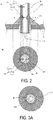
- FIG. 2A is an enlarged vertical cross-sectional view illustrating an example of section A in FIG. 1
- FIG. 2B is a horizontal cross-sectional view taken along line X-X in FIG. 2A . Note that in the subsequent figures, the same members will be denoted by the same reference signs.
- cells 3 are arranged uprightly in a row, and each include a gas flow passage (not illustrated) through which gas flows from one end to another end inside the cell.
- the cells 3 adjacent to each other are electrically connected in series via a conductive member (not illustrated).
- the cell stack device 1 illustrated in FIG. 1 includes one cell stack 5 in which lower ends of the cells 3 are fixed to a manifold 4 with an insulating adhesive (not illustrated) such as a glass sealing material.
- a reformer 6 serving as a gas supply portion configured to generate gas to be supplied to the cells 3 is disposed above the cell stack 5. Note that in the following description, the gas supply portion will be described as the reformer 6 unless otherwise noted.
- an end conductive member 11 is disposed at an end portion of the cell stack 5.
- the end conductive member 11 includes a conductive portion 12 and is configured to collect electricity generated by power generation in the cell stack 5 (cells 3) and draw the electricity to the outside.
- cell stack device 1 can also include the reformer 6.
- a hollow flat plate-shaped cell including a plurality of gas flow passages in which gas flows in a lengthwise direction is given as an example of the cell 3 in FIG. 1 .
- the cell 3 is a solid oxide cell formed by sequentially stacking an inner electrode layer, a solid electrolyte layer, and an outer electrode layer on a surface of a support body including the gas flow passages.
- the inner electrode layer will be described as a fuel electrode layer
- the outer electrode layer will be described as an oxygen electrode layer unless otherwise noted.
- a portion in which the fuel electrode layer and the oxygen electrode layer face each other via the solid electrolyte layer functions as a power generating element. That is, oxygen-containing gas such as air flows outside the oxygen electrode layer, and fuel gas (hydrogen-containing gas) flows in the gas flow passages inside the support body. The oxygen-containing gas and the fuel gas are heated to a predetermined actuation temperature to generate power. Then, electrical current generated by such power generation is collected via the end conductive member 11 described above.
- the reformer 6 illustrated in FIG. 1 reforms raw fuel such as natural gas and kerosene supplied via a raw fuel supply pipe 10, and generates gas.
- the reformer 6 can adopt a structure capable of performing steam reforming that is very efficient reforming reaction, and includes a vaporizing portion 7 configured to vaporize water and a reforming portion 8 in which a reforming catalyst (not illustrated) that reforms raw fuel into gas is disposed. Then, the gas generated in the reformer 6 is supplied to the manifold 4 via a gas supply pipe 9, and is supplied from the manifold 4 to the gas flow passages provided inside the cells 3.
- FIG. 1 the gas supply pipe 9 and the manifold 4 are illustrated in a cross-sectional view, and the rest is illustrated in a side view.
- the gas supply pipe 9 includes one end connected to the reformer 6, and another end inserted into a first through hole 14 provided in the manifold 4, and is joined to the manifold 4 via a first joining portion 17.
- the gas supply pipe 9 includes a first protruding portion 19 protruding toward an inner side of the gas supply pipe 9 and located at a position corresponding to the first joining portion 17. Accordingly, even when the gas supply pipe 9 is deformed or moves, due to the first protruding portion 19, a thickness t1 of the gas supply pipe 9 at the first protruding portion 19 is increased at the position corresponding to the first joining portion 17, and thus cross-sectional area of the gas supply pipe 9 increases, and generation of cracking or chipping due to fatigue breakage or the like in the first joining portion 17 joined to the gas supply pipe 9 can be suppressed. Accordingly, the gas supply pipe 9 and the manifold 4 can be joined firmly, and as a result, joining reliability between the gas supply pipe 9 and the manifold 4 can be improved.
- the thickness t1 of the gas supply pipe 9 at the first protruding portion 19 is a thickness obtained by adding a maximum thickness t12 of the first protruding portion 19 to a thickness t11 of the gas supply pipe 9 itself.
- the first protruding portion 19 can be provided along an entire circumference of an inner surface of the gas supply pipe 9 from a viewpoint of increasing the cross-sectional area of the gas supply pipe 9. Accordingly, generation of cracking or chipping due to fatigue breakage or the like in the first joining portion 17 joined to the gas supply pipe 9 can be suppressed.
- FIG. 3A , FIG. 3B, and FIG. 3C is a horizontal cross-sectional view illustrating another example of FIG. 2B .
- FIG. 3A and FIG. 3B illustrates an example in which a thickness of the gas supply pipe 9 at the first protruding portion 19 is uneven along an entire circumference.
- a thin portion and a thick portion may be line-symmetrical. Further, as in FIG. 3B , the thin portion and the thick portion may be eccentric. As described above, even when the thickness of the gas supply pipe 9 at the first protruding portion 19 is uneven along the entire circumference, the gas supply pipe 9 remains thick without change, and generation of cracking or chipping due to the portion can be suppressed.
- the first protruding portion 19 is not necessarily required to be provided along the entire circumference. As in FIG. 3C , the first protruding portion 19 may be provided partially. Even in the case where the first protruding portion 19 is provided partially as described above, generation of cracking or chipping due to the portion at which the gas supply pipe 9 is thick can be suppressed.
- the thickness of the gas supply pipe 9 can be, for example, from 0.5 mm to 1.0 mm, and the thickness of the first protruding portion 19 can be, for example, from 0.1 mm to 0.5 mm.
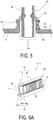
- FIG. 4 and FIG. 5 is an enlarged vertical cross-sectional view illustrating another example of section A of FIG. 1 .
- a first bent portion 4c extending toward the reformer 6 side along the gas supply pipe 9 is provided in an outer periphery of the first through hole 14 in the manifold 4, and an upper end portion of the first bent portion 4c and the gas supply pipe 9 are joined via the first joining portion 17.
- the manifold 4 includes the first bent portion 4c, and thus the manifold 4 and the gas supply pipe 9 are joined easily. Further, the gas supply pipe 9 is inserted into the first through hole 14 easily.
- a height H1 of the first bent portion 4c can be, for example, from 2 mm to 5 mm.
- a thickness t3 of the upper end portion of the first bent portion 4c is larger than a thickness t4 of a center portion the first bent portion 4c and smaller than a thickness t5 of a lower end portion of the first bent portion 4c.
- the first bent portion 4c has such a shape that the center portion is recessed with respect to the upper end portion and the lower end portion expands. Accordingly, cross-sectional area of the upper end portion of the first bent portion 4c increases, and hence the upper end portion of the first bent portion 4c and the gas supply pipe 9 are firmly joined via the first joining portion 17.
- the center portion is recessed with respect to the upper end portion of the first bent portion 4c, and thus the thickness t4 of the center portion is the smallest among the thickness t3, the thickness t4, and the thickness t5.
- This center portion having a small thickness can relieve stress generated when the gas supply pipe 9 is deformed or moves. Accordingly, the gas supply pipe 9 and the manifold 4 can be joined firmly. Furthermore, the lower end portion of the first bent portion 4c expands, and accordingly an angle formed between the first bent portion 4c and the manifold 4 is obtuse to obtain a gently-sloping shape. Hence, stress generated when the gas supply pipe 9 is deformed or moves can be relieved. As a result, generation of cracking or chipping between the first bent portion 4c and the manifold 4 can be suppressed.
- the thickness t3 can be, for example, 0.6 mm to 0.8 mm
- the thickness t4 can be, for example, 0.5 mm to 0.6 mm
- the thickness t5 can be, for example, from 0.9 mm to 1.2 mm.
- FIG. 6A is an external perspective view illustrating another example of a cell stack device according to the present embodiment
- FIG. 6B is a plan view of the cell stack device illustrated in FIG. 6A with a portion of the cell stack device being not illustrated
- FIG. 7 is a cross-sectional view taken along line Y-Y in FIG. 6B and illustrating a gas supply pipe 9, a manifold 4, and a straightening plate 16, and the rest is illustrated in a side view.
- the manifold 4 of a cell stack device 111 illustrated in FIG. 6A , FIG. 6B, and FIG. 7 includes a main body portion 4a including a space communicated with gas flow passages, and a flange portion 4b protruding from the main body portion 4a. Gas is supplied to cells 3 via the space in the main body portion 4a. Another end of the gas supply pipe 9 is inserted from a first surface n1 side into a first through hole 14 provided penetrating the flange portion 4b, and is joined to the manifold 4, and is further inserted from a second surface n2 side into a second through hole 15 provided penetrating the main body portion 4a and is joined with the manifold 4.
- the manifold 4 includes the straightening plate 16 spaced apart from the other end of the gas supply pipe 9 and covering the other end.
- the straightening plate 16 is provided perpendicularly to a flow-out direction of gas flowing out through the second through hole 15.
- the straightening plate 16 includes an opening portion. The opening portion may be provided such that the gas flows toward the cells 3 at an end portion of a cell stack 5 being away from the straightening plate 16.
- the first surface n1 and the second surface n2 refer to, in the manifold 4, a surface on the side on which the cell stack 5 is joined and mounted, and a surface on the opposite side to the first surface, respectively.
- FIG. 8A is an enlarged vertical cross-sectional view illustrating an example of section B in FIG. 7
- FIG. 8B is a horizontal cross-sectional view taken along line Z-Z in FIG. 8A
- the other end of the gas supply pipe 9 and the manifold 4 are joined via a second joining portion 18.
- the gas supply pipe 9 includes a second protruding portion 20 protruding toward an inner side of the gas supply pipe 9 and located at a position corresponding to the second joining portion 18.
- the thickness t2 of the gas supply pipe 9 at the second protruding portion 20 is a thickness obtained by adding a maximum thickness t22 of the second protruding portion 20 to a thickness t21 of the gas supply pipe 9 itself.
- the second protruding portion 20 can be provided along an entire circumference of an inner surface of the gas supply pipe 9 from a viewpoint of increasing the cross-sectional area of the gas supply pipe 9. Accordingly, generation of cracking or chipping due to fatigue breakage or the like in the first joining portion 17 joined to the gas supply pipe 9 can be suppressed.
- FIG. 9A , FIG. 9B, and FIG. 9C is a horizontal cross-sectional view illustrating another example of FIG. 8B .
- FIG. 9A and FIG. 9B illustrates an example in which a thickness of the gas supply pipe 9 at the second protruding portion 20 is uneven along an entire circumference.
- a thin portion and a thick portion may be line-symmetrical. Further, as in FIG. 9B , the thin portion and the thick portion may be eccentric. As described above, even when the thickness of the gas supply pipe 9 at the second protruding portion 20 is uneven along the entire circumference, the gas supply pipe 9 remains thick without change, and generation of cracking or chipping due to the portion can be suppressed.
- the second protruding portion 20 is not necessarily required to be provided along the entire circumference. As in FIG. 9C , the second protruding portion 20 may be provided partially. Even in the case where the second protruding portion 20 is provided partially as described above, generation of cracking or chipping due to the portion at which the gas supply pipe 9 is thick can be suppressed.
- the thickness of the gas supply pipe 9 can be, for example, from 0.5 mm to 1.0 mm, and the thickness of the second protruding portion 20 can be, for example, from 0.1 mm to 0.5 mm.
- FIG. 10 and FIG. 11 is an enlarged vertical cross-sectional view illustrating another example of section B of FIG. 7 .
- a second bent portion 4d extending toward a reformer 6 side along the gas supply pipe 9 is provided in an outer periphery of the second through hole 15 in the manifold 4, and an upper end portion of the second bent portion 4d and the gas supply pipe 9 are joined via the second joining portion 18.
- the manifold 4 includes the second bent portion 4d, and thus the manifold 4 and the gas supply pipe 9 are joined easily. Further, the gas supply pipe 9 is inserted into the second through hole 15 easily.
- a height H2 of the second bent portion 4d can be, for example, from 2 mm to 5 mm.
- a thickness t6 of an upper end portion of the second bent portion 4d is larger than a thickness t7 of a center portion the second bent portion 4d and smaller than a thickness t8 of a lower end portion of the second bent portion 4d.
- the second bent portion 4d has such a shape that the center portion is recessed with respect to the upper end portion and the lower end portion expands. Accordingly, cross-sectional area of the upper end portion of the second bent portion 4d increases, and thus the upper end portion of the second bent portion 4d and the gas supply pipe 9 are firmly joined via the second joining portion 18.
- the center portion is recessed with respect to the upper end portion, and thus the thickness t7 of the center portion is the smallest among the thickness t6, the thickness t7, and the thickness t8.
- This center portion having a small thickness can relieve stress generated when the gas supply pipe 9 is deformed or moves. Accordingly, the gas supply pipe 9 and the manifold 4 can be joined firmly.
- the lower end portion of the second bent portion 4d expands, and accordingly an angle formed between the second bent portion 4d and the manifold 4 is obtuse to obtain a gently-sloping shape. Hence, stress generated when the gas supply pipe 9 is deformed or moves can be relieved. As a result, generation of cracking or chipping between the second bent portion 4d and the manifold 4 can be suppressed.
- the thickness t6 can be, for example, 0.6 mm to 0.8 mm
- the thickness t7 can be, for example, from 0.5 mm to 0.6 mm
- the thickness t8 can be, for example, from 0.9 mm to 1.2 mm.
- the first through hole 14 is formed by penetrating the flange portion 4b by a processing method such as punching.
- the second through hole 15 is also formed by penetrating the main body portion 4a by a processing method such as punching.
- the first joining portion 17 and the second joining portion 18 to which the gas supply pipe 9 and the manifold 4 are joined can be provided by joining an outer surface of the manifold 4 and the gas supply pipe 9 by using a metallurgical joining method.
- the metallurgical joining method is a method of performing joining by fusion welding, pressure welding, or soldering.
- the fusion welding include laser welding, plasma arc welding, inert gas arc welding, MAG welding, or gas welding.
- examples of the pressure welding include ultrasonic welding, friction welding, or explosive welding.
- first bent portion 4c and the second bent portion 4d integrally with the outer peripheries of the first through hole 14 and the second through hole 15, respectively in the manifold 4
- a processing method such as pressing using dies having shapes of the first bent portion 4c and the second bent portion 4d can be performed.
- members having shapes of the first bent portion 4c and the second bent portion 4d may be prepared, and the respective members may be joined to the outer peripheries of the first through hole 14 and the second through hole 15 by the metallurgical joining method described above.
- FIG. 12 is an external perspective view illustrating an example of a fuel cell module serving as a module including the cell stack device 111 housed in a housing container, and the cell stack device 111 illustrated in FIG. 6A is housed inside a housing container 22 having a rectangular parallelepiped shape.
- the reformer 6 configured to generate fuel gas by reforming raw fuel such as natural gas and kerosene is disposed above the cell stack 5. Then, the fuel gas generated in the reformer 6 is supplied to the manifold 4 via the gas supply pipe 9, and is supplied, via the manifold 4, to the gas flow passages provided inside the cells 3.
- FIG. 12 illustrates a state in which portions (front and back surfaces) of the housing container 22 are detached and the cell stack device 111 and the reformer 6 housed inside are removed to the rear.
- the cell stack device 111 can be housed in the housing container 22 by being slid into the housing container 22.
- the cell stack device 111 may include the reformer 6.
- the cell stack device 111 described above is housed in the housing container 22, and hence the module 30 with improved durability can be obtained.
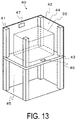
- FIG. 13 is a perspective view illustrating an example of a fuel cell device serving as a module housing device in which the module 30 illustrated in FIG. 12 and an auxiliary device configured to operate the cell stack device 111 are housed in an external casing. Note that a portion of the configuration is omitted in FIG. 13 .
- the external casing including supports 41 and exterior plates 42 is divided into an upper section and a lower section by a dividing plate 43.
- the upper section serves as a module housing chamber 44 that houses the module 30 described above.
- the lower section serves as an auxiliary device housing chamber 45 that houses the auxiliary device configured to operate the module 30. Note that the auxiliary device housed in the auxiliary device housing chamber 45 is not illustrated.
- an airflow hole 46 is provided in the dividing plate 43.
- the airflow hole 46 is configured to cause air in the auxiliary device housing chamber 45 to flow into the module housing chamber 44.
- An exhaust hole 47 is provided in a portion of the outer plates 42 constituting the module housing chamber 44. The exhaust hole 47 is configured to discharge air inside the module housing chamber 44.
- the module 30 with improved durability is housed in the module housing chamber 44, and accordingly the module housing device 40 with improved durability can be obtained.
Landscapes
- Life Sciences & Earth Sciences (AREA)
- Engineering & Computer Science (AREA)
- Manufacturing & Machinery (AREA)
- Sustainable Development (AREA)
- Sustainable Energy (AREA)
- Chemical & Material Sciences (AREA)
- Chemical Kinetics & Catalysis (AREA)
- Electrochemistry (AREA)
- General Chemical & Material Sciences (AREA)
- Fuel Cell (AREA)
Abstract
Description
- The present disclosure relates to a cell stack device, a module, and a module housing device.
- In recent years, as a next-generation energy source, for example,
JP 5766132 B - Further, for example,
JP 5873949 B - A cell stack device according to the present disclosure includes a cell stack in which a plurality of cells having a cylindrical shape and including gas flow passages are arranged uprightly and are electrically connected, a manifold configured to fix lower ends of the plurality of cells and supply gas to the gas flow passages of the plurality of cells, and a gas supply pipe configured to supply the gas to the manifold. The gas supply pipe includes one end connected to a gas supply portion and another end inserted into a first through hole provided in the manifold, and is joined to the manifold via a first joining portion. The gas supply pipe includes a first protruding portion protruding toward an inner side of the gas supply pipe and located at a position corresponding to the first joining portion in any cross-section along an insertion direction of the gas supply pipe.
- A module according to the present disclosure includes the cell stack device housed in a housing container.
- A module housing device according to the present disclosure includes the module and an auxiliary device configured to operate the module. The module and the auxiliary device are housed in an external casing.
-
-
FIG. 1 is a side view and a partial cross-sectional view illustrating an example of a cell stack device according to a present embodiment. -
FIG. 2A is an enlarged vertical cross-sectional view illustrating an example of section A inFIG. 1 , andFIG. 2B is a horizontal cross-sectional view taken along line X-X inFIG. 2A . -
FIG. 3A is a horizontal cross-sectional view illustrating another example ofFIG. 2B . -
FIG. 3B is a horizontal cross-sectional view illustrating another example ofFIG. 2B . -
FIG. 3C is a horizontal cross-sectional view illustrating another example ofFIG. 2B . -
FIG. 4 is an enlarged vertical cross-sectional view illustrating another example of section A ofFIG. 1 . -
FIG. 5 is an enlarged vertical cross-sectional view illustrating another example of section A ofFIG. 1 . -
FIG. 6A is an external perspective view illustrating another example of a cell stack device according to the present embodiment. -
FIG. 6B is a plan view of the cell stack device illustrated inFIG. 6A with a portion of the cell stack device being not illustrated. -
FIG. 7 is a cross-sectional view taken along line Y-Y inFIG. 6B with a portion being illustrated in a side view. -
FIG. 8A is an enlarged vertical cross-sectional view illustrating an example of section B inFIG. 7 , andFIG. 8B is a horizontal cross-sectional view taken along line Z-Z inFIG. 8A . -
FIG. 9A is a horizontal cross-sectional view illustrating another example ofFIG. 8B . -
FIG. 9B is a horizontal cross-sectional view illustrating another example ofFIG. 8B . -
FIG. 9C is a horizontal cross-sectional view illustrating another example ofFIG. 8B . -
FIG. 10 is an enlarged vertical cross-sectional view illustrating another example of section B ofFIG. 7 . -
FIG. 11 is an enlarged vertical cross-sectional view illustrating another example of section B ofFIG. 7 . -
FIG. 12 is an external perspective view illustrating an example of a module according to the present embodiment. -
FIG. 13 is a perspective view illustrating an example of a module housing device according to the present embodiment with a portion of the module housing device being not illustrated. - With reference to
FIGS. 1 to 13 , description will be made on an example of a cell stack device, a module, and a module housing device according to the present disclosure. -
FIG. 1 is a side view illustrating an example of the cell stack device according to a present embodiment and a portion of the cell stack device is illustrated in a partial cross-sectional view for ease of understanding. Further,FIG. 2A is an enlarged vertical cross-sectional view illustrating an example of section A inFIG. 1 , andFIG. 2B is a horizontal cross-sectional view taken along line X-X inFIG. 2A . Note that in the subsequent figures, the same members will be denoted by the same reference signs. - In a
cell stack device 1 illustrated inFIG. 1 ,cells 3 are arranged uprightly in a row, and each include a gas flow passage (not illustrated) through which gas flows from one end to another end inside the cell. Thecells 3 adjacent to each other are electrically connected in series via a conductive member (not illustrated). Moreover, thecell stack device 1 illustrated inFIG. 1 includes onecell stack 5 in which lower ends of thecells 3 are fixed to amanifold 4 with an insulating adhesive (not illustrated) such as a glass sealing material. - Further, a
reformer 6 serving as a gas supply portion configured to generate gas to be supplied to thecells 3 is disposed above thecell stack 5. Note that in the following description, the gas supply portion will be described as thereformer 6 unless otherwise noted. - Further, an end
conductive member 11 is disposed at an end portion of thecell stack 5. The endconductive member 11 includes aconductive portion 12 and is configured to collect electricity generated by power generation in the cell stack 5 (cells 3) and draw the electricity to the outside. - Note that the
cell stack device 1 can also include thereformer 6. - Further, a hollow flat plate-shaped cell including a plurality of gas flow passages in which gas flows in a lengthwise direction is given as an example of the
cell 3 inFIG. 1 . Thecell 3 is a solid oxide cell formed by sequentially stacking an inner electrode layer, a solid electrolyte layer, and an outer electrode layer on a surface of a support body including the gas flow passages. Note that in the following description, the inner electrode layer will be described as a fuel electrode layer, and the outer electrode layer will be described as an oxygen electrode layer unless otherwise noted. - Here, in the
cell 3, a portion in which the fuel electrode layer and the oxygen electrode layer face each other via the solid electrolyte layer functions as a power generating element. That is, oxygen-containing gas such as air flows outside the oxygen electrode layer, and fuel gas (hydrogen-containing gas) flows in the gas flow passages inside the support body. The oxygen-containing gas and the fuel gas are heated to a predetermined actuation temperature to generate power. Then, electrical current generated by such power generation is collected via the endconductive member 11 described above. - Further, the
reformer 6 illustrated inFIG. 1 reforms raw fuel such as natural gas and kerosene supplied via a rawfuel supply pipe 10, and generates gas. Note that thereformer 6 can adopt a structure capable of performing steam reforming that is very efficient reforming reaction, and includes a vaporizingportion 7 configured to vaporize water and a reformingportion 8 in which a reforming catalyst (not illustrated) that reforms raw fuel into gas is disposed. Then, the gas generated in thereformer 6 is supplied to themanifold 4 via agas supply pipe 9, and is supplied from themanifold 4 to the gas flow passages provided inside thecells 3. - Note that in
FIG. 1 , thegas supply pipe 9 and themanifold 4 are illustrated in a cross-sectional view, and the rest is illustrated in a side view. - Further, in the present embodiment, the
gas supply pipe 9 includes one end connected to thereformer 6, and another end inserted into a first throughhole 14 provided in themanifold 4, and is joined to themanifold 4 via a first joiningportion 17. - Meanwhile, in the
cell stack device 1, in a case where thegas supply pipe 9 is deformed or moves due to heat generated at the time of power generation of the fuel cells, there may be a risk that cracking or chipping due to fatigue breakage or the like may be generated in the first joiningportion 17 between thegas supply pipe 9 and themanifold 4, depending on the shape of thegas supply pipe 9. Thus, there has been room for improvement in firmly joining thegas supply pipe 9 and themanifold 4. - In view of this, in the present embodiment, as illustrated in
FIG. 2A , thegas supply pipe 9 includes a first protrudingportion 19 protruding toward an inner side of thegas supply pipe 9 and located at a position corresponding to the first joiningportion 17. Accordingly, even when thegas supply pipe 9 is deformed or moves, due to the first protrudingportion 19, a thickness t1 of thegas supply pipe 9 at the first protrudingportion 19 is increased at the position corresponding to the first joiningportion 17, and thus cross-sectional area of thegas supply pipe 9 increases, and generation of cracking or chipping due to fatigue breakage or the like in the first joiningportion 17 joined to thegas supply pipe 9 can be suppressed. Accordingly, thegas supply pipe 9 and themanifold 4 can be joined firmly, and as a result, joining reliability between thegas supply pipe 9 and themanifold 4 can be improved. - Here, as illustrated in
FIG. 2A and FIG. 2B , the thickness t1 of thegas supply pipe 9 at the first protrudingportion 19 is a thickness obtained by adding a maximum thickness t12 of the first protrudingportion 19 to a thickness t11 of thegas supply pipe 9 itself. - As illustrated in
FIG. 2B , the first protrudingportion 19 can be provided along an entire circumference of an inner surface of thegas supply pipe 9 from a viewpoint of increasing the cross-sectional area of thegas supply pipe 9. Accordingly, generation of cracking or chipping due to fatigue breakage or the like in the first joiningportion 17 joined to thegas supply pipe 9 can be suppressed. - Each of
FIG. 3A ,FIG. 3B, and FIG. 3C is a horizontal cross-sectional view illustrating another example ofFIG. 2B . - Each of
FIG. 3A andFIG. 3B illustrates an example in which a thickness of thegas supply pipe 9 at the first protrudingportion 19 is uneven along an entire circumference. - As in
FIG. 3A , a thin portion and a thick portion may be line-symmetrical. Further, as inFIG. 3B , the thin portion and the thick portion may be eccentric. As described above, even when the thickness of thegas supply pipe 9 at the first protrudingportion 19 is uneven along the entire circumference, thegas supply pipe 9 remains thick without change, and generation of cracking or chipping due to the portion can be suppressed. - On the other hand, the first protruding
portion 19 is not necessarily required to be provided along the entire circumference. As inFIG. 3C , the first protrudingportion 19 may be provided partially. Even in the case where the first protrudingportion 19 is provided partially as described above, generation of cracking or chipping due to the portion at which thegas supply pipe 9 is thick can be suppressed. - The thickness of the
gas supply pipe 9 can be, for example, from 0.5 mm to 1.0 mm, and the thickness of the first protrudingportion 19 can be, for example, from 0.1 mm to 0.5 mm. - Each of
FIG. 4 andFIG. 5 is an enlarged vertical cross-sectional view illustrating another example of section A ofFIG. 1 . - In an example illustrated in
FIG. 4 , a firstbent portion 4c extending toward thereformer 6 side along thegas supply pipe 9 is provided in an outer periphery of the first throughhole 14 in themanifold 4, and an upper end portion of the firstbent portion 4c and thegas supply pipe 9 are joined via the first joiningportion 17. Themanifold 4 includes the firstbent portion 4c, and thus themanifold 4 and thegas supply pipe 9 are joined easily. Further, thegas supply pipe 9 is inserted into the first throughhole 14 easily. Note that a height H1 of the firstbent portion 4c can be, for example, from 2 mm to 5 mm. - In the example illustrated in
FIG. 5 , a thickness t3 of the upper end portion of the firstbent portion 4c is larger than a thickness t4 of a center portion the firstbent portion 4c and smaller than a thickness t5 of a lower end portion of the firstbent portion 4c. In other words, the firstbent portion 4c has such a shape that the center portion is recessed with respect to the upper end portion and the lower end portion expands. Accordingly, cross-sectional area of the upper end portion of the firstbent portion 4c increases, and hence the upper end portion of the firstbent portion 4c and thegas supply pipe 9 are firmly joined via the first joiningportion 17. Moreover, the center portion is recessed with respect to the upper end portion of the firstbent portion 4c, and thus the thickness t4 of the center portion is the smallest among the thickness t3, the thickness t4, and the thickness t5. This center portion having a small thickness can relieve stress generated when thegas supply pipe 9 is deformed or moves. Accordingly, thegas supply pipe 9 and themanifold 4 can be joined firmly. Furthermore, the lower end portion of the firstbent portion 4c expands, and accordingly an angle formed between the firstbent portion 4c and themanifold 4 is obtuse to obtain a gently-sloping shape. Hence, stress generated when thegas supply pipe 9 is deformed or moves can be relieved. As a result, generation of cracking or chipping between the firstbent portion 4c and themanifold 4 can be suppressed. - At the first
bent portion 4c, the thickness t3 can be, for example, 0.6 mm to 0.8 mm, the thickness t4 can be, for example, 0.5 mm to 0.6 mm, and the thickness t5 can be, for example, from 0.9 mm to 1.2 mm. -
FIG. 6A is an external perspective view illustrating another example of a cell stack device according to the present embodiment, andFIG. 6B is a plan view of the cell stack device illustrated inFIG. 6A with a portion of the cell stack device being not illustrated. Further,FIG. 7 is a cross-sectional view taken along line Y-Y inFIG. 6B and illustrating agas supply pipe 9, amanifold 4, and a straighteningplate 16, and the rest is illustrated in a side view. - The
manifold 4 of acell stack device 111 illustrated inFIG. 6A ,FIG. 6B, and FIG. 7 includes amain body portion 4a including a space communicated with gas flow passages, and aflange portion 4b protruding from themain body portion 4a. Gas is supplied tocells 3 via the space in themain body portion 4a. Another end of thegas supply pipe 9 is inserted from a first surface n1 side into a first throughhole 14 provided penetrating theflange portion 4b, and is joined to themanifold 4, and is further inserted from a second surface n2 side into a second throughhole 15 provided penetrating themain body portion 4a and is joined with themanifold 4. Then, themanifold 4 includes the straighteningplate 16 spaced apart from the other end of thegas supply pipe 9 and covering the other end. In other words, to improve a flow distribution ratio, the straighteningplate 16 is provided perpendicularly to a flow-out direction of gas flowing out through the second throughhole 15. Further, the straighteningplate 16 includes an opening portion. The opening portion may be provided such that the gas flows toward thecells 3 at an end portion of acell stack 5 being away from the straighteningplate 16. Note that, the first surface n1 and the second surface n2 refer to, in themanifold 4, a surface on the side on which thecell stack 5 is joined and mounted, and a surface on the opposite side to the first surface, respectively. -
FIG. 8A is an enlarged vertical cross-sectional view illustrating an example of section B inFIG. 7 , andFIG. 8B is a horizontal cross-sectional view taken along line Z-Z inFIG. 8A . In the present embodiment, the other end of thegas supply pipe 9 and themanifold 4 are joined via a second joiningportion 18. Here, in the present embodiment, as illustrated inFIG. 8A , thegas supply pipe 9 includes a second protrudingportion 20 protruding toward an inner side of thegas supply pipe 9 and located at a position corresponding to the second joiningportion 18. Accordingly, even when thegas supply pipe 9 is deformed or moves, due to the second protrudingportion 20, a thickness t2 of thegas supply pipe 9 at the second protrudingportion 20 is increased at the position corresponding to the second joiningportion 18, and thus cross-sectional area of thegas supply pipe 9 increases, and generation of cracking or chipping due to fatigue breakage or the like in the second joiningportion 18 joined to thegas supply pipe 9 can be suppressed. Accordingly, thegas supply pipe 9 and themanifold 4 can be joined firmly, and as a result, joining reliability between thegas supply pipe 9 and themanifold 4 can be improved. - Here, as illustrated in
FIG. 8A and FIG. 8B , the thickness t2 of thegas supply pipe 9 at the second protrudingportion 20 is a thickness obtained by adding a maximum thickness t22 of the second protrudingportion 20 to a thickness t21 of thegas supply pipe 9 itself. - As illustrated in
FIG. 8B , the second protrudingportion 20 can be provided along an entire circumference of an inner surface of thegas supply pipe 9 from a viewpoint of increasing the cross-sectional area of thegas supply pipe 9. Accordingly, generation of cracking or chipping due to fatigue breakage or the like in the first joiningportion 17 joined to thegas supply pipe 9 can be suppressed. - Each of
FIG. 9A ,FIG. 9B, and FIG. 9C is a horizontal cross-sectional view illustrating another example ofFIG. 8B . - Each of
FIG. 9A andFIG. 9B illustrates an example in which a thickness of thegas supply pipe 9 at the second protrudingportion 20 is uneven along an entire circumference. - As in
FIG. 9A , a thin portion and a thick portion may be line-symmetrical. Further, as inFIG. 9B , the thin portion and the thick portion may be eccentric. As described above, even when the thickness of thegas supply pipe 9 at the second protrudingportion 20 is uneven along the entire circumference, thegas supply pipe 9 remains thick without change, and generation of cracking or chipping due to the portion can be suppressed. - On the other hand, the second protruding
portion 20 is not necessarily required to be provided along the entire circumference. As inFIG. 9C , the second protrudingportion 20 may be provided partially. Even in the case where the second protrudingportion 20 is provided partially as described above, generation of cracking or chipping due to the portion at which thegas supply pipe 9 is thick can be suppressed. - The thickness of the
gas supply pipe 9 can be, for example, from 0.5 mm to 1.0 mm, and the thickness of the second protrudingportion 20 can be, for example, from 0.1 mm to 0.5 mm. - Each of
FIG. 10 andFIG. 11 is an enlarged vertical cross-sectional view illustrating another example of section B ofFIG. 7 . - In an example illustrated in
FIG. 10 , a secondbent portion 4d extending toward areformer 6 side along thegas supply pipe 9 is provided in an outer periphery of the second throughhole 15 in themanifold 4, and an upper end portion of the secondbent portion 4d and thegas supply pipe 9 are joined via the second joiningportion 18. Themanifold 4 includes the secondbent portion 4d, and thus themanifold 4 and thegas supply pipe 9 are joined easily. Further, thegas supply pipe 9 is inserted into the second throughhole 15 easily. Note that a height H2 of the secondbent portion 4d can be, for example, from 2 mm to 5 mm. - In the example illustrated in
FIG. 11 , a thickness t6 of an upper end portion of the secondbent portion 4d is larger than a thickness t7 of a center portion the secondbent portion 4d and smaller than a thickness t8 of a lower end portion of the secondbent portion 4d. In other words, the secondbent portion 4d has such a shape that the center portion is recessed with respect to the upper end portion and the lower end portion expands. Accordingly, cross-sectional area of the upper end portion of the secondbent portion 4d increases, and thus the upper end portion of the secondbent portion 4d and thegas supply pipe 9 are firmly joined via the second joiningportion 18. Moreover, the center portion is recessed with respect to the upper end portion, and thus the thickness t7 of the center portion is the smallest among the thickness t6, the thickness t7, and the thickness t8. This center portion having a small thickness can relieve stress generated when thegas supply pipe 9 is deformed or moves. Accordingly, thegas supply pipe 9 and themanifold 4 can be joined firmly. Furthermore, the lower end portion of the secondbent portion 4d expands, and accordingly an angle formed between the secondbent portion 4d and themanifold 4 is obtuse to obtain a gently-sloping shape. Hence, stress generated when thegas supply pipe 9 is deformed or moves can be relieved. As a result, generation of cracking or chipping between the secondbent portion 4d and themanifold 4 can be suppressed. - At the second
bent portion 4d, the thickness t6 can be, for example, 0.6 mm to 0.8 mm, the thickness t7 can be, for example, from 0.5 mm to 0.6 mm, and the thickness t8 can be, for example, from 0.9 mm to 1.2 mm. - Description will be made on an example of a method of manufacturing the
manifold 4 according to the present embodiment described above. In the following, detailed description will be made on a method of manufacturing themanifold 4 as illustrated in, for example,FIG. 7 in which the first throughhole 14 is formed in theflange portion 4b and the second throughhole 15 is formed in themain body portion 4a. - The first through
hole 14 is formed by penetrating theflange portion 4b by a processing method such as punching. Similarly, the second throughhole 15 is also formed by penetrating themain body portion 4a by a processing method such as punching. - The first joining
portion 17 and the second joiningportion 18 to which thegas supply pipe 9 and themanifold 4 are joined can be provided by joining an outer surface of themanifold 4 and thegas supply pipe 9 by using a metallurgical joining method. The metallurgical joining method is a method of performing joining by fusion welding, pressure welding, or soldering. Examples of the fusion welding include laser welding, plasma arc welding, inert gas arc welding, MAG welding, or gas welding. Further, examples of the pressure welding include ultrasonic welding, friction welding, or explosive welding. - Further, to provide the first
bent portion 4c and the secondbent portion 4d integrally with the outer peripheries of the first throughhole 14 and the second throughhole 15, respectively in themanifold 4, a processing method such as pressing using dies having shapes of the firstbent portion 4c and the secondbent portion 4d can be performed. Further, in a case where the firstbent portion 4c and the secondbent portion 4d are provided separately from the outer peripheries of the first throughhole 14 and the second throughhole 15, respectively, members having shapes of the firstbent portion 4c and the secondbent portion 4d may be prepared, and the respective members may be joined to the outer peripheries of the first throughhole 14 and the second throughhole 15 by the metallurgical joining method described above. -
FIG. 12 is an external perspective view illustrating an example of a fuel cell module serving as a module including thecell stack device 111 housed in a housing container, and thecell stack device 111 illustrated inFIG. 6A is housed inside ahousing container 22 having a rectangular parallelepiped shape. - Note that for the purpose of obtaining fuel gas to be used in the
cells 3, thereformer 6 configured to generate fuel gas by reforming raw fuel such as natural gas and kerosene is disposed above thecell stack 5. Then, the fuel gas generated in thereformer 6 is supplied to themanifold 4 via thegas supply pipe 9, and is supplied, via themanifold 4, to the gas flow passages provided inside thecells 3. - Note that
FIG. 12 illustrates a state in which portions (front and back surfaces) of thehousing container 22 are detached and thecell stack device 111 and thereformer 6 housed inside are removed to the rear. In amodule 30 illustrated inFIG. 12 , thecell stack device 111 can be housed in thehousing container 22 by being slid into thehousing container 22. Note that thecell stack device 111 may include thereformer 6. - Further, in the
module 30 according to the present embodiment, thecell stack device 111 described above is housed in thehousing container 22, and hence themodule 30 with improved durability can be obtained. -
FIG. 13 is a perspective view illustrating an example of a fuel cell device serving as a module housing device in which themodule 30 illustrated inFIG. 12 and an auxiliary device configured to operate thecell stack device 111 are housed in an external casing. Note that a portion of the configuration is omitted inFIG. 13 . - In a
module housing device 40 illustrated inFIG. 13 , the external casing including supports 41 andexterior plates 42 is divided into an upper section and a lower section by a dividingplate 43. The upper section serves as amodule housing chamber 44 that houses themodule 30 described above. The lower section serves as an auxiliarydevice housing chamber 45 that houses the auxiliary device configured to operate themodule 30. Note that the auxiliary device housed in the auxiliarydevice housing chamber 45 is not illustrated. - Further, an
airflow hole 46 is provided in the dividingplate 43. Theairflow hole 46 is configured to cause air in the auxiliarydevice housing chamber 45 to flow into themodule housing chamber 44. Anexhaust hole 47 is provided in a portion of theouter plates 42 constituting themodule housing chamber 44. Theexhaust hole 47 is configured to discharge air inside themodule housing chamber 44. - As described above, in the
module housing device 40, themodule 30 with improved durability is housed in themodule housing chamber 44, and accordingly themodule housing device 40 with improved durability can be obtained. - Note that, for example, in the embodiment described above, the description is made by using so-called vertical cells; however, horizontal cells referred to commonly as horizontal cells in which a plurality of power generating elements are provided on a support substrate, or so-called cylindrical cells can also be used.
-
- 1, 111 Cell stack device
- 3 Cell
- 4 Manifold
- 4a Main body portion
- 4b Flange portion
- 4c First bent portion
- 4d Second bent portion
- 5 Cell stack
- 6 Gas supply portion (reformer)
- 9 Gas supply pipe
- 14 First through hole
- 15 Second through hole
- 17 First joining portion
- 18 Second joining portion
- 19 First protruding portion
- 20 Second protruding portion
- 30 Module (fuel cell module)
- 40 Module housing device (fuel cell device)
- t1 Thickness of gas supply pipe at first protruding portion
- t11 Thickness of gas supply pipe itself
- t12 Maximum thickness of first protruding portion
- t2 Thickness of gas supply pipe at second protruding portion
- t21 Thickness of gas supply pipe itself
- t22 Maximum thickness of second protruding portion
Claims (12)
- A cell stack device comprising:a cell stack in which a plurality of cells having a cylindrical shape and including gas flow passages are arranged uprightly and are electrically connected,a manifold configured to fix lower ends of the plurality of cells and supply gas to the gas flow passages of the plurality of cells, anda gas supply pipe configured to supply the gas to the manifold, whereinthe gas supply pipe includes one end connected to a gas supply portion and another end inserted into a first through hole provided in the manifold, and is joined to the manifold via a first joining portion, andthe gas supply pipe includes a first protruding portion protruding toward an inner side of the gas supply pipe and located at a position corresponding to the first joining portion in any cross-section along an insertion direction of the gas supply pipe.
- The cell stack device according to claim 1, wherein the first protruding portion is provided along an entire circumference of an inner surface of the gas supply pipe.
- The cell stack device according to claim 2, wherein a thickness of the gas supply pipe at the first protruding portion is uneven along an entire circumference.
- The cell stack device according to any one of claims 1 to 3, wherein
a first bent portion extending toward a side of the gas supply portion along the gas supply pipe is provided in an outer periphery of the first through hole in the manifold, and
an upper end portion of the first bent portion and the gas supply pipe are joined via the first joining portion. - The cell stack device according to claim 4, wherein a thickness of an upper end portion of the first bent portion is larger than a thickness of a center portion of the first bent portion, and is smaller than a thickness of a lower end portion of the first bent portion.
- The cell stack device according to any one of claims 1 to 5, wherein
the manifold includes a main body portion including a space communicated with the gas flow passages, and a flange portion protruding from the main body portion,
the flange portion includes the first through hole, and the main body portion includes a second through hole,
another end of the gas supply pipe is inserted into the second through hole, and the other end and the manifold are joined via a second joining portion, and
the gas supply pipe includes a second protruding portion protruding toward an inner side of the gas supply pipe and located at a position corresponding to the second joining portion in any cross-section along an insertion direction of the gas supply pipe. - The cell stack device according to claim 6, wherein the second protruding portion is provided along an entire circumference of the inner surface of the gas supply pipe.
- The cell stack device according to claim 7, wherein a thickness of the gas supply pipe at the second protruding portion is uneven along an entire circumference.
- The cell stack device according to any one of claims 6 to 8, wherein
a second bent portion extending toward a side of the gas supply portion along the gas supply pipe is provided in an outer periphery of the second through hole in the manifold, and
an upper end portion of the second bent portion and the gas supply pipe are joined. - The cell stack device according to claim 9, wherein a thickness of an upper end portion of the second bent portion is larger than a thickness of a center portion of the second bent portion, and is smaller than a thickness of a lower end portion of the second bent portion.
- A module comprising:
the cell stack device according to any one of claims 1 to 10 housed in a housing container. - A module housing device comprising:the module according to claim 11; andan auxiliary device configured to operate the module, whereinthe module and the auxiliary device are housed in an external casing.
Applications Claiming Priority (2)
| Application Number | Priority Date | Filing Date | Title |
|---|---|---|---|
| JP2017086310 | 2017-04-25 | ||
| PCT/JP2018/011783 WO2018198619A1 (en) | 2017-04-25 | 2018-03-23 | Cell stack device, module and module housing device |
Publications (3)
| Publication Number | Publication Date |
|---|---|
| EP3618158A1 true EP3618158A1 (en) | 2020-03-04 |
| EP3618158A4 EP3618158A4 (en) | 2021-01-06 |
| EP3618158B1 EP3618158B1 (en) | 2021-08-11 |
Family
ID=63919035
Family Applications (1)
| Application Number | Title | Priority Date | Filing Date |
|---|---|---|---|
| EP18790819.9A Active EP3618158B1 (en) | 2017-04-25 | 2018-03-23 | Cell stack device, module and module housing device |
Country Status (5)
| Country | Link |
|---|---|
| US (2) | US11239486B2 (en) |
| EP (1) | EP3618158B1 (en) |
| JP (1) | JP6438179B1 (en) |
| CN (2) | CN110521043B (en) |
| WO (1) | WO2018198619A1 (en) |
Families Citing this family (1)
| Publication number | Priority date | Publication date | Assignee | Title |
|---|---|---|---|---|
| JP6705931B1 (en) * | 2018-12-04 | 2020-06-03 | 日本碍子株式会社 | Cell stack device |
Family Cites Families (22)
| Publication number | Priority date | Publication date | Assignee | Title |
|---|---|---|---|---|
| JP4032383B2 (en) * | 2002-09-25 | 2008-01-16 | 臼井国際産業株式会社 | FUEL RAIL, FUEL RAIL MAIN TUBE AND METHOD FOR PRODUCING THE SAME |
| JP4587659B2 (en) * | 2003-11-26 | 2010-11-24 | 京セラ株式会社 | Manufacturing method of fuel cell stack |
| JP5046484B2 (en) * | 2004-12-22 | 2012-10-10 | 京セラ株式会社 | Fuel reformer storage container and fuel reformer |
| US20060204826A1 (en) * | 2005-03-09 | 2006-09-14 | Ion America Corporation | Geometric feature driven flow equalization in fuel cell stack gas flow separator |
| JP5033324B2 (en) * | 2005-11-30 | 2012-09-26 | 京セラ株式会社 | Fuel cell stack and fuel cell |
| JP5334456B2 (en) * | 2008-05-28 | 2013-11-06 | 京セラ株式会社 | Cell stack device, fuel cell module, and fuel cell device |
| JP5334732B2 (en) * | 2009-07-29 | 2013-11-06 | 京セラ株式会社 | Cell stack device, fuel cell module, and fuel cell device |
| CN201875308U (en) * | 2010-12-13 | 2011-06-22 | 张宇 | Pipe joint |
| JP5766132B2 (en) | 2012-01-30 | 2015-08-19 | 京セラ株式会社 | Cell stack device and fuel cell device |
| CN104335404B (en) * | 2012-06-04 | 2016-11-09 | 本田技研工业株式会社 | Water cut-off structure of gas outlet area in fuel cell stack |
| JP5946730B2 (en) * | 2012-09-13 | 2016-07-06 | ダイニチ工業株式会社 | Fuel cell module |
| DE102012219014A1 (en) * | 2012-10-18 | 2014-04-24 | Tyco Electronics Austria Gmbh | Switching device i.e. relay, has switching contact that is spaced apart from first counter-contact and second mating contact in position, where switching contact is mounted on spring element |
| DE102012219104A1 (en) * | 2012-10-19 | 2014-05-08 | Robert Bosch Gmbh | Electrochemical cell with tubular carrier grid |
| CN103996868B (en) * | 2013-02-18 | 2016-06-15 | 本田技研工业株式会社 | Fuel cell pack |
| CN103363245A (en) * | 2013-06-25 | 2013-10-23 | 洛阳凯诺知识产权咨询服务有限公司 | Reinforcing structure for weak part of pipeline |
| JP6110488B2 (en) * | 2013-06-28 | 2017-04-05 | 京セラ株式会社 | Cell unit, cell stack device, cell unit device and module |
| WO2015030215A1 (en) * | 2013-08-31 | 2015-03-05 | 京セラ株式会社 | Cell, cell stack device, module and module-containing device |
| EP3076467B1 (en) * | 2013-11-28 | 2019-09-11 | Kyocera Corporation | Cell stack device, module, and module housing device |
| CN106233519B (en) * | 2014-04-21 | 2019-04-05 | 京瓷株式会社 | Battery stack device, module, and module housing device |
| JP5873949B1 (en) * | 2014-10-21 | 2016-03-01 | 日本碍子株式会社 | Fuel manifold |
| JP6043455B1 (en) * | 2015-08-11 | 2016-12-14 | 日本碍子株式会社 | Fuel cell stack structure |
| JP6893308B2 (en) * | 2016-04-26 | 2021-06-23 | パナソニックIpマネジメント株式会社 | Fuel cell device |
-
2018
- 2018-03-23 WO PCT/JP2018/011783 patent/WO2018198619A1/en not_active Ceased
- 2018-03-23 JP JP2018541368A patent/JP6438179B1/en active Active
- 2018-03-23 EP EP18790819.9A patent/EP3618158B1/en active Active
- 2018-03-23 CN CN201880025037.6A patent/CN110521043B/en active Active
- 2018-03-23 US US16/608,219 patent/US11239486B2/en active Active
- 2018-03-23 CN CN202210447773.9A patent/CN114824401B/en active Active
-
2021
- 2021-12-17 US US17/553,861 patent/US11658327B2/en active Active
Also Published As
| Publication number | Publication date |
|---|---|
| CN114824401A (en) | 2022-07-29 |
| CN114824401B (en) | 2024-08-20 |
| EP3618158B1 (en) | 2021-08-11 |
| US11658327B2 (en) | 2023-05-23 |
| JPWO2018198619A1 (en) | 2019-06-27 |
| WO2018198619A1 (en) | 2018-11-01 |
| CN110521043A (en) | 2019-11-29 |
| JP6438179B1 (en) | 2018-12-12 |
| US11239486B2 (en) | 2022-02-01 |
| EP3618158A4 (en) | 2021-01-06 |
| CN110521043B (en) | 2022-05-24 |
| US20200052321A1 (en) | 2020-02-13 |
| US20220109176A1 (en) | 2022-04-07 |
Similar Documents
| Publication | Publication Date | Title |
|---|---|---|
| US11742510B2 (en) | Cell stack device, module, and module housing device | |
| KR100773654B1 (en) | Fuel cell and fuel cell stack | |
| JP5696234B2 (en) | Fuel cell and fuel cell stack | |
| WO2014017097A1 (en) | Fuel cell, and fuel cell stack | |
| JP4351619B2 (en) | Fuel cell | |
| US11658327B2 (en) | Cell stack device, module, and module housing device | |
| EP3291344B1 (en) | Fuel-cell power generation unit and fuel-cell stack | |
| US11695131B2 (en) | Fuel cell and fuel cell system for an aircraft | |
| JP2005294180A (en) | Fuel cell and fuel cell stack | |
| JP4989028B2 (en) | Fuel cell | |
| JP6621541B2 (en) | Electrochemical reaction cell stack, interconnector-electrochemical reaction single cell complex, and method for producing electrochemical reaction cell stack | |
| JP2008235060A (en) | Fuel cell separator | |
| JP2016207270A (en) | Fuel cell stack and power generation module | |
| JP4351617B2 (en) | Fuel cell | |
| JP6403569B2 (en) | Fuel cell hot module | |
| JP2016058212A (en) | Fuel battery module | |
| CN114094155B (en) | Interconnect boards for fuel cells and fuel cell systems for aircraft | |
| JP7169333B2 (en) | Electrochemical reaction cell stack | |
| WO2010125945A1 (en) | Fuel cell module | |
| CN114094155A (en) | Interconnect plate for fuel cell and fuel cell system for aircraft | |
| JP2020170630A (en) | Electrochemical reaction cell stack | |
| JP2018006035A (en) | Cell stack device, module and module housing device |
Legal Events
| Date | Code | Title | Description |
|---|---|---|---|
| STAA | Information on the status of an ep patent application or granted ep patent |
Free format text: STATUS: THE INTERNATIONAL PUBLICATION HAS BEEN MADE |
|
| PUAI | Public reference made under article 153(3) epc to a published international application that has entered the european phase |
Free format text: ORIGINAL CODE: 0009012 |
|
| STAA | Information on the status of an ep patent application or granted ep patent |
Free format text: STATUS: REQUEST FOR EXAMINATION WAS MADE |
|
| 17P | Request for examination filed |
Effective date: 20191024 |
|
| AK | Designated contracting states |
Kind code of ref document: A1 Designated state(s): AL AT BE BG CH CY CZ DE DK EE ES FI FR GB GR HR HU IE IS IT LI LT LU LV MC MK MT NL NO PL PT RO RS SE SI SK SM TR |
|
| AX | Request for extension of the european patent |
Extension state: BA ME |
|
| DAV | Request for validation of the european patent (deleted) | ||
| DAX | Request for extension of the european patent (deleted) | ||
| A4 | Supplementary search report drawn up and despatched |
Effective date: 20201208 |
|
| RIC1 | Information provided on ipc code assigned before grant |
Ipc: H01M 8/12 20160101ALI20201202BHEP Ipc: H01M 8/124 20160101ALN20201202BHEP Ipc: H01M 8/04 20160101AFI20201202BHEP Ipc: H01M 8/04082 20160101ALI20201202BHEP Ipc: H01M 8/243 20160101ALI20201202BHEP Ipc: H01M 8/2485 20160101ALI20201202BHEP |
|
| GRAP | Despatch of communication of intention to grant a patent |
Free format text: ORIGINAL CODE: EPIDOSNIGR1 |
|
| STAA | Information on the status of an ep patent application or granted ep patent |
Free format text: STATUS: GRANT OF PATENT IS INTENDED |
|
| RIC1 | Information provided on ipc code assigned before grant |
Ipc: H01M 8/2485 20160101ALI20210304BHEP Ipc: H01M 8/12 20160101ALI20210304BHEP Ipc: H01M 8/04082 20160101ALI20210304BHEP Ipc: H01M 8/124 20160101ALN20210304BHEP Ipc: H01M 8/243 20160101ALI20210304BHEP Ipc: H01M 8/04 20160101AFI20210304BHEP |
|
| INTG | Intention to grant announced |
Effective date: 20210319 |
|
| GRAS | Grant fee paid |
Free format text: ORIGINAL CODE: EPIDOSNIGR3 |
|
| GRAA | (expected) grant |
Free format text: ORIGINAL CODE: 0009210 |
|
| STAA | Information on the status of an ep patent application or granted ep patent |
Free format text: STATUS: THE PATENT HAS BEEN GRANTED |
|
| AK | Designated contracting states |
Kind code of ref document: B1 Designated state(s): AL AT BE BG CH CY CZ DE DK EE ES FI FR GB GR HR HU IE IS IT LI LT LU LV MC MK MT NL NO PL PT RO RS SE SI SK SM TR |
|
| REG | Reference to a national code |
Ref country code: CH Ref legal event code: EP |
|
| REG | Reference to a national code |
Ref country code: DE Ref legal event code: R096 Ref document number: 602018021788 Country of ref document: DE |
|
| REG | Reference to a national code |
Ref country code: IE Ref legal event code: FG4D Ref country code: AT Ref legal event code: REF Ref document number: 1420316 Country of ref document: AT Kind code of ref document: T Effective date: 20210915 |
|
| REG | Reference to a national code |
Ref country code: LT Ref legal event code: MG9D |
|
| REG | Reference to a national code |
Ref country code: NL Ref legal event code: MP Effective date: 20210811 |
|
| REG | Reference to a national code |
Ref country code: AT Ref legal event code: MK05 Ref document number: 1420316 Country of ref document: AT Kind code of ref document: T Effective date: 20210811 |
|
| PG25 | Lapsed in a contracting state [announced via postgrant information from national office to epo] |
Ref country code: RS Free format text: LAPSE BECAUSE OF FAILURE TO SUBMIT A TRANSLATION OF THE DESCRIPTION OR TO PAY THE FEE WITHIN THE PRESCRIBED TIME-LIMIT Effective date: 20210811 Ref country code: SE Free format text: LAPSE BECAUSE OF FAILURE TO SUBMIT A TRANSLATION OF THE DESCRIPTION OR TO PAY THE FEE WITHIN THE PRESCRIBED TIME-LIMIT Effective date: 20210811 Ref country code: HR Free format text: LAPSE BECAUSE OF FAILURE TO SUBMIT A TRANSLATION OF THE DESCRIPTION OR TO PAY THE FEE WITHIN THE PRESCRIBED TIME-LIMIT Effective date: 20210811 Ref country code: FI Free format text: LAPSE BECAUSE OF FAILURE TO SUBMIT A TRANSLATION OF THE DESCRIPTION OR TO PAY THE FEE WITHIN THE PRESCRIBED TIME-LIMIT Effective date: 20210811 Ref country code: ES Free format text: LAPSE BECAUSE OF FAILURE TO SUBMIT A TRANSLATION OF THE DESCRIPTION OR TO PAY THE FEE WITHIN THE PRESCRIBED TIME-LIMIT Effective date: 20210811 Ref country code: NO Free format text: LAPSE BECAUSE OF FAILURE TO SUBMIT A TRANSLATION OF THE DESCRIPTION OR TO PAY THE FEE WITHIN THE PRESCRIBED TIME-LIMIT Effective date: 20211111 Ref country code: PT Free format text: LAPSE BECAUSE OF FAILURE TO SUBMIT A TRANSLATION OF THE DESCRIPTION OR TO PAY THE FEE WITHIN THE PRESCRIBED TIME-LIMIT Effective date: 20211213 Ref country code: BG Free format text: LAPSE BECAUSE OF FAILURE TO SUBMIT A TRANSLATION OF THE DESCRIPTION OR TO PAY THE FEE WITHIN THE PRESCRIBED TIME-LIMIT Effective date: 20211111 Ref country code: AT Free format text: LAPSE BECAUSE OF FAILURE TO SUBMIT A TRANSLATION OF THE DESCRIPTION OR TO PAY THE FEE WITHIN THE PRESCRIBED TIME-LIMIT Effective date: 20210811 Ref country code: LT Free format text: LAPSE BECAUSE OF FAILURE TO SUBMIT A TRANSLATION OF THE DESCRIPTION OR TO PAY THE FEE WITHIN THE PRESCRIBED TIME-LIMIT Effective date: 20210811 |
|
| PG25 | Lapsed in a contracting state [announced via postgrant information from national office to epo] |
Ref country code: PL Free format text: LAPSE BECAUSE OF FAILURE TO SUBMIT A TRANSLATION OF THE DESCRIPTION OR TO PAY THE FEE WITHIN THE PRESCRIBED TIME-LIMIT Effective date: 20210811 Ref country code: LV Free format text: LAPSE BECAUSE OF FAILURE TO SUBMIT A TRANSLATION OF THE DESCRIPTION OR TO PAY THE FEE WITHIN THE PRESCRIBED TIME-LIMIT Effective date: 20210811 Ref country code: GR Free format text: LAPSE BECAUSE OF FAILURE TO SUBMIT A TRANSLATION OF THE DESCRIPTION OR TO PAY THE FEE WITHIN THE PRESCRIBED TIME-LIMIT Effective date: 20211112 |
|
| PG25 | Lapsed in a contracting state [announced via postgrant information from national office to epo] |
Ref country code: NL Free format text: LAPSE BECAUSE OF FAILURE TO SUBMIT A TRANSLATION OF THE DESCRIPTION OR TO PAY THE FEE WITHIN THE PRESCRIBED TIME-LIMIT Effective date: 20210811 |
|
| PG25 | Lapsed in a contracting state [announced via postgrant information from national office to epo] |
Ref country code: DK Free format text: LAPSE BECAUSE OF FAILURE TO SUBMIT A TRANSLATION OF THE DESCRIPTION OR TO PAY THE FEE WITHIN THE PRESCRIBED TIME-LIMIT Effective date: 20210811 |
|
| REG | Reference to a national code |
Ref country code: DE Ref legal event code: R097 Ref document number: 602018021788 Country of ref document: DE |
|
| PG25 | Lapsed in a contracting state [announced via postgrant information from national office to epo] |
Ref country code: SM Free format text: LAPSE BECAUSE OF FAILURE TO SUBMIT A TRANSLATION OF THE DESCRIPTION OR TO PAY THE FEE WITHIN THE PRESCRIBED TIME-LIMIT Effective date: 20210811 Ref country code: SK Free format text: LAPSE BECAUSE OF FAILURE TO SUBMIT A TRANSLATION OF THE DESCRIPTION OR TO PAY THE FEE WITHIN THE PRESCRIBED TIME-LIMIT Effective date: 20210811 Ref country code: RO Free format text: LAPSE BECAUSE OF FAILURE TO SUBMIT A TRANSLATION OF THE DESCRIPTION OR TO PAY THE FEE WITHIN THE PRESCRIBED TIME-LIMIT Effective date: 20210811 Ref country code: EE Free format text: LAPSE BECAUSE OF FAILURE TO SUBMIT A TRANSLATION OF THE DESCRIPTION OR TO PAY THE FEE WITHIN THE PRESCRIBED TIME-LIMIT Effective date: 20210811 Ref country code: CZ Free format text: LAPSE BECAUSE OF FAILURE TO SUBMIT A TRANSLATION OF THE DESCRIPTION OR TO PAY THE FEE WITHIN THE PRESCRIBED TIME-LIMIT Effective date: 20210811 Ref country code: AL Free format text: LAPSE BECAUSE OF FAILURE TO SUBMIT A TRANSLATION OF THE DESCRIPTION OR TO PAY THE FEE WITHIN THE PRESCRIBED TIME-LIMIT Effective date: 20210811 |
|
| PLBE | No opposition filed within time limit |
Free format text: ORIGINAL CODE: 0009261 |
|
| STAA | Information on the status of an ep patent application or granted ep patent |
Free format text: STATUS: NO OPPOSITION FILED WITHIN TIME LIMIT |
|
| 26N | No opposition filed |
Effective date: 20220512 |
|
| PG25 | Lapsed in a contracting state [announced via postgrant information from national office to epo] |
Ref country code: IT Free format text: LAPSE BECAUSE OF FAILURE TO SUBMIT A TRANSLATION OF THE DESCRIPTION OR TO PAY THE FEE WITHIN THE PRESCRIBED TIME-LIMIT Effective date: 20210811 |
|
| PG25 | Lapsed in a contracting state [announced via postgrant information from national office to epo] |
Ref country code: SI Free format text: LAPSE BECAUSE OF FAILURE TO SUBMIT A TRANSLATION OF THE DESCRIPTION OR TO PAY THE FEE WITHIN THE PRESCRIBED TIME-LIMIT Effective date: 20210811 |
|
| PG25 | Lapsed in a contracting state [announced via postgrant information from national office to epo] |
Ref country code: MC Free format text: LAPSE BECAUSE OF FAILURE TO SUBMIT A TRANSLATION OF THE DESCRIPTION OR TO PAY THE FEE WITHIN THE PRESCRIBED TIME-LIMIT Effective date: 20210811 |
|
| REG | Reference to a national code |
Ref country code: CH Ref legal event code: PL |
|
| REG | Reference to a national code |
Ref country code: BE Ref legal event code: MM Effective date: 20220331 |
|
| PG25 | Lapsed in a contracting state [announced via postgrant information from national office to epo] |
Ref country code: LU Free format text: LAPSE BECAUSE OF NON-PAYMENT OF DUE FEES Effective date: 20220323 Ref country code: LI Free format text: LAPSE BECAUSE OF NON-PAYMENT OF DUE FEES Effective date: 20220331 Ref country code: IE Free format text: LAPSE BECAUSE OF NON-PAYMENT OF DUE FEES Effective date: 20220323 Ref country code: FR Free format text: LAPSE BECAUSE OF NON-PAYMENT OF DUE FEES Effective date: 20220331 Ref country code: CH Free format text: LAPSE BECAUSE OF NON-PAYMENT OF DUE FEES Effective date: 20220331 |
|
| PG25 | Lapsed in a contracting state [announced via postgrant information from national office to epo] |
Ref country code: BE Free format text: LAPSE BECAUSE OF NON-PAYMENT OF DUE FEES Effective date: 20220331 |
|
| P01 | Opt-out of the competence of the unified patent court (upc) registered |
Effective date: 20230508 |
|
| PG25 | Lapsed in a contracting state [announced via postgrant information from national office to epo] |
Ref country code: MK Free format text: LAPSE BECAUSE OF FAILURE TO SUBMIT A TRANSLATION OF THE DESCRIPTION OR TO PAY THE FEE WITHIN THE PRESCRIBED TIME-LIMIT Effective date: 20210811 Ref country code: CY Free format text: LAPSE BECAUSE OF FAILURE TO SUBMIT A TRANSLATION OF THE DESCRIPTION OR TO PAY THE FEE WITHIN THE PRESCRIBED TIME-LIMIT Effective date: 20210811 |
|
| PG25 | Lapsed in a contracting state [announced via postgrant information from national office to epo] |
Ref country code: HU Free format text: LAPSE BECAUSE OF FAILURE TO SUBMIT A TRANSLATION OF THE DESCRIPTION OR TO PAY THE FEE WITHIN THE PRESCRIBED TIME-LIMIT; INVALID AB INITIO Effective date: 20180323 |
|
| PG25 | Lapsed in a contracting state [announced via postgrant information from national office to epo] |
Ref country code: MT Free format text: LAPSE BECAUSE OF FAILURE TO SUBMIT A TRANSLATION OF THE DESCRIPTION OR TO PAY THE FEE WITHIN THE PRESCRIBED TIME-LIMIT Effective date: 20210811 |
|
| PG25 | Lapsed in a contracting state [announced via postgrant information from national office to epo] |
Ref country code: TR Free format text: LAPSE BECAUSE OF FAILURE TO SUBMIT A TRANSLATION OF THE DESCRIPTION OR TO PAY THE FEE WITHIN THE PRESCRIBED TIME-LIMIT Effective date: 20210811 |
|
| PGFP | Annual fee paid to national office [announced via postgrant information from national office to epo] |
Ref country code: GB Payment date: 20260202 Year of fee payment: 9 |
|
| PGFP | Annual fee paid to national office [announced via postgrant information from national office to epo] |
Ref country code: DE Payment date: 20260128 Year of fee payment: 9 |