EP3618139A1 - Battery test system and battery test method - Google Patents
Battery test system and battery test method Download PDFInfo
- Publication number
- EP3618139A1 EP3618139A1 EP19180735.3A EP19180735A EP3618139A1 EP 3618139 A1 EP3618139 A1 EP 3618139A1 EP 19180735 A EP19180735 A EP 19180735A EP 3618139 A1 EP3618139 A1 EP 3618139A1
- Authority
- EP
- European Patent Office
- Prior art keywords
- battery
- application
- extrusion apparatus
- test method
- battery test
- Prior art date
- Legal status (The legal status is an assumption and is not a legal conclusion. Google has not performed a legal analysis and makes no representation as to the accuracy of the status listed.)
- Granted
Links
Images



Classifications
-
- G—PHYSICS
- G01—MEASURING; TESTING
- G01R—MEASURING ELECTRIC VARIABLES; MEASURING MAGNETIC VARIABLES
- G01R31/00—Arrangements for testing electric properties; Arrangements for locating electric faults; Arrangements for electrical testing characterised by what is being tested not provided for elsewhere
- G01R31/36—Arrangements for testing, measuring or monitoring the electrical condition of accumulators or electric batteries, e.g. capacity or state of charge [SoC]
- G01R31/385—Arrangements for measuring battery or accumulator variables
- G01R31/3865—Arrangements for measuring battery or accumulator variables related to manufacture, e.g. testing after manufacture
-
- G—PHYSICS
- G01—MEASURING; TESTING
- G01R—MEASURING ELECTRIC VARIABLES; MEASURING MAGNETIC VARIABLES
- G01R31/00—Arrangements for testing electric properties; Arrangements for locating electric faults; Arrangements for electrical testing characterised by what is being tested not provided for elsewhere
- G01R31/36—Arrangements for testing, measuring or monitoring the electrical condition of accumulators or electric batteries, e.g. capacity or state of charge [SoC]
- G01R31/378—Arrangements for testing, measuring or monitoring the electrical condition of accumulators or electric batteries, e.g. capacity or state of charge [SoC] specially adapted for the type of battery or accumulator
-
- G—PHYSICS
- G01—MEASURING; TESTING
- G01R—MEASURING ELECTRIC VARIABLES; MEASURING MAGNETIC VARIABLES
- G01R31/00—Arrangements for testing electric properties; Arrangements for locating electric faults; Arrangements for electrical testing characterised by what is being tested not provided for elsewhere
- G01R31/36—Arrangements for testing, measuring or monitoring the electrical condition of accumulators or electric batteries, e.g. capacity or state of charge [SoC]
- G01R31/382—Arrangements for monitoring battery or accumulator variables, e.g. SoC
- G01R31/3835—Arrangements for monitoring battery or accumulator variables, e.g. SoC involving only voltage measurements
-
- H—ELECTRICITY
- H01—ELECTRIC ELEMENTS
- H01M—PROCESSES OR MEANS, e.g. BATTERIES, FOR THE DIRECT CONVERSION OF CHEMICAL ENERGY INTO ELECTRICAL ENERGY
- H01M10/00—Secondary cells; Manufacture thereof
- H01M10/42—Methods or arrangements for servicing or maintenance of secondary cells or secondary half-cells
- H01M10/4285—Testing apparatus
-
- H—ELECTRICITY
- H01—ELECTRIC ELEMENTS
- H01M—PROCESSES OR MEANS, e.g. BATTERIES, FOR THE DIRECT CONVERSION OF CHEMICAL ENERGY INTO ELECTRICAL ENERGY
- H01M10/00—Secondary cells; Manufacture thereof
- H01M10/42—Methods or arrangements for servicing or maintenance of secondary cells or secondary half-cells
- H01M10/48—Accumulators combined with arrangements for measuring, testing or indicating the condition of cells, e.g. the level or density of the electrolyte
-
- H—ELECTRICITY
- H01—ELECTRIC ELEMENTS
- H01M—PROCESSES OR MEANS, e.g. BATTERIES, FOR THE DIRECT CONVERSION OF CHEMICAL ENERGY INTO ELECTRICAL ENERGY
- H01M10/00—Secondary cells; Manufacture thereof
- H01M10/42—Methods or arrangements for servicing or maintenance of secondary cells or secondary half-cells
- H01M10/48—Accumulators combined with arrangements for measuring, testing or indicating the condition of cells, e.g. the level or density of the electrolyte
- H01M10/486—Accumulators combined with arrangements for measuring, testing or indicating the condition of cells, e.g. the level or density of the electrolyte for measuring temperature
-
- H—ELECTRICITY
- H01—ELECTRIC ELEMENTS
- H01M—PROCESSES OR MEANS, e.g. BATTERIES, FOR THE DIRECT CONVERSION OF CHEMICAL ENERGY INTO ELECTRICAL ENERGY
- H01M10/00—Secondary cells; Manufacture thereof
- H01M10/05—Accumulators with non-aqueous electrolyte
- H01M10/052—Li-accumulators
-
- H—ELECTRICITY
- H01—ELECTRIC ELEMENTS
- H01M—PROCESSES OR MEANS, e.g. BATTERIES, FOR THE DIRECT CONVERSION OF CHEMICAL ENERGY INTO ELECTRICAL ENERGY
- H01M50/00—Constructional details or processes of manufacture of the non-active parts of electrochemical cells other than fuel cells, e.g. hybrid cells
- H01M50/10—Primary casings; Jackets or wrappings
- H01M50/102—Primary casings; Jackets or wrappings characterised by their shape or physical structure
- H01M50/103—Primary casings; Jackets or wrappings characterised by their shape or physical structure prismatic or rectangular
-
- H—ELECTRICITY
- H01—ELECTRIC ELEMENTS
- H01M—PROCESSES OR MEANS, e.g. BATTERIES, FOR THE DIRECT CONVERSION OF CHEMICAL ENERGY INTO ELECTRICAL ENERGY
- H01M50/00—Constructional details or processes of manufacture of the non-active parts of electrochemical cells other than fuel cells, e.g. hybrid cells
- H01M50/50—Current conducting connections for cells or batteries
- H01M50/543—Terminals
- H01M50/547—Terminals characterised by the disposition of the terminals on the cells
- H01M50/55—Terminals characterised by the disposition of the terminals on the cells on the same side of the cell
-
- H—ELECTRICITY
- H01—ELECTRIC ELEMENTS
- H01M—PROCESSES OR MEANS, e.g. BATTERIES, FOR THE DIRECT CONVERSION OF CHEMICAL ENERGY INTO ELECTRICAL ENERGY
- H01M50/00—Constructional details or processes of manufacture of the non-active parts of electrochemical cells other than fuel cells, e.g. hybrid cells
- H01M50/50—Current conducting connections for cells or batteries
- H01M50/543—Terminals
- H01M50/552—Terminals characterised by their shape
- H01M50/553—Terminals adapted for prismatic, pouch or rectangular cells
- H01M50/557—Plate-shaped terminals
-
- Y—GENERAL TAGGING OF NEW TECHNOLOGICAL DEVELOPMENTS; GENERAL TAGGING OF CROSS-SECTIONAL TECHNOLOGIES SPANNING OVER SEVERAL SECTIONS OF THE IPC; TECHNICAL SUBJECTS COVERED BY FORMER USPC CROSS-REFERENCE ART COLLECTIONS [XRACs] AND DIGESTS
- Y02—TECHNOLOGIES OR APPLICATIONS FOR MITIGATION OR ADAPTATION AGAINST CLIMATE CHANGE
- Y02E—REDUCTION OF GREENHOUSE GAS [GHG] EMISSIONS, RELATED TO ENERGY GENERATION, TRANSMISSION OR DISTRIBUTION
- Y02E60/00—Enabling technologies; Technologies with a potential or indirect contribution to GHG emissions mitigation
- Y02E60/10—Energy storage using batteries
Definitions
- This application relates to the field of battery tests, and in particular, to a battery test system and a battery test method.
- Lithium-ion batteries have been widely used in various fields such as electronic products and electric vehicles.
- a UL 1642 (Lithium Batteries) impact test is currently used for testing safety performance of a lithium-ion battery after the lithium-ion battery is rapidly impacted.
- the soft package battery is usually severely damaged and even broken directly after being impacted.
- the UL 1642 impact test is too strict to objectively reflect the safety performance during actual use of the soft pack battery.
- One aspect of this application is to provide a battery test system and a battery test method that are applicable to the test of a soft package battery.
- One embodiment of this application provides a battery test system, including: an extrusion apparatus configured to be disposed on a first surface of a battery; and a pressure apparatus disposed above the extrusion apparatus, wherein the pressure apparatus is configured to apply a predetermined force to the battery in predetermined duration through the extrusion apparatus.
- the pressure apparatus is configured to descend at a predetermined speed to contact the extrusion apparatus.
- a contact surface of the extrusion apparatus with the first surface of the battery is a substantially flat surface.
- the extrusion apparatus is a batten, and a longitudinal section shape of the batten is square, triangular, circular, or semi-circular.
- a side edge of the contact surface of the extrusion apparatus has a chamfer.
- the chamfer has a radius of a circular arc from about 0.5 mm to about 5 mm.
- the extrusion apparatus is fastened to the first surface of the battery with glue or a fastening tape.
- the battery test system further includes a carrying apparatus, wherein a second surface of the battery is configured to be disposed on the carrying apparatus, and the second surface is opposite to the first surface.
- Another embodiment of this application provides a battery test method, including: disposing an extrusion apparatus on a first surface of a battery; and applying a predetermined force to the extrusion apparatus through a pressure apparatus to squeeze the battery and keep so for a predetermined time.
- the step of applying a predetermined force to the extrusion apparatus through a pressure apparatus includes: descending the pressure apparatus at a predetermined speed to contact the extrusion apparatus.
- the predetermined speed ranges from about 0.5 mm/s to about 100 mm/s.
- the test method further includes: collecting battery parameters of the battery by a data collection apparatus, the battery parameters including temperatures and voltages of the battery.
- the test method further includes: disposing a second surface of the battery on a carrying apparatus, and the second surface is opposite to the first surface.
- the step of collecting battery parameters of the battery includes: collecting the battery parameters of the battery after the battery squeezed by the extrusion device is stored at room temperature for the predetermined time.
- the test method further includes: testing with a normal battery, and determining, by changing the predetermined force and/or the predetermined time, a critical value where battery parameters of the normal battery start to change.
- the battery test system and the battery test method provided in this application are able to reasonably evaluate the safety of the soft package battery and identify the risk caused by the defect of the soft package battery.
- relativistic wordings such as “central”, “longitudinal”, “lateral”, “front”, “back”, “right”, “left”, “inner”, “outer”, “relatively low”, “relatively high”, “horizontal”, “vertical”, “higher than”, “lower than”, “above”, “below”, “top”, “bottom”, and derived wordings thereof (such as “horizontally”, “downward”, and “upward") should be construed as referenced directions described in discussion or shown in the accompanying drawings. These relativistic wordings are merely for ease of description, and require constructing or operating this application in a particular direction.
- the terms when being used in combination with a value, the terms may refer to a variation range being less than or equal to ⁇ 10% of the value, for example, less than or equal to ⁇ 5%, less than or equal to ⁇ 4%, less than or equal to ⁇ 3%, less than or equal to ⁇ 2%, less than or equal to ⁇ 1%, less than or equal to ⁇ 0.5%, less than or equal to ⁇ 0.1%, or less than or equal to ⁇ 0.05%.
- a difference between two values is less than or equal to ⁇ 10% of an average value of the values (for example, less than or equal to ⁇ 5%, less than or equal to ⁇ 4%, less than or equal to ⁇ 3%, less than or equal to ⁇ 2%, less than or equal to ⁇ 1%, less than or equal to ⁇ 0.5%, less than or equal to ⁇ 0.1%, or less than or equal to ⁇ 0.05%), it could be considered that the two values are "substantially" the same or "approximate”.
- first”, “second”, “third”, and the like may be used for distinguishing between different components in a diagram or a series of diagrams.
- the terms “first”, “second”, “third”, and the like are not intended to describe corresponding components.
- wordings such as “dispose”, “connect”, “couple”, “fix”, and similar wordings thereof are widely used, and a person skilled in the art may understand, based on a specific case, the foregoing wordings as, for example, fixedly connected, detachably connected, or integrally connected, or may be mechanically connected or electronically connected, or may be directly connected or indirectly connected by using an intermediate structure; or may be internal communication between two components.
- the UL 1642 impact test is disposing a round bar with a diameter of 15.8 mm ⁇ 0.1 mm at the center of a battery, and then making an iron block with a weight of 9.1 kg ⁇ 0.46 kg freely fall from a height of 610 mm ⁇ 25 mm to impact the battery.
- a criterion of a qualified battery is no fire and no explosion.
- the method for directly impacting the soft package battery by using the heavy object and the round bar is not suitable.
- the situation in which a housing of the battery is broken or the battery is broken due to an impact rarely occurs. Therefore, in the UL 1642 impact test, the situation that would occur during actual use of the soft package battery is not ideally tested. Consequently, the safety of the battery cannot be appropriately estimated, and a safety risk caused by a defect in the battery cannot be identified.
- the safety test has sufficient pertinence and applicability, thereby exerting a maximum value for testing a risk of the battery.
- the battery test system includes an extrusion apparatus configured to be disposed on a surface of the battery, and a pressure apparatus disposed above the extrusion apparatus.
- the pressure apparatus applies a predetermined force to the battery in predetermined duration through the extrusion apparatus, so that a local part of the battery is continuously squeezed to a predetermined extent.
- the battery test system may simulate a case in which the battery is easily damaged when the battery is used in a terminal system, thereby effectively estimating the safety performance of the battery after being squeezed. If a defect exists in the battery, a short circuit may occur, and even cause a case where leakage, smoking, or fire occurs. Therefore, according to the battery test system provided in this application, the quality and safety level of the battery can be directly determined, thereby identifying an inner defect and a risk of the battery. Preferred embodiments of the battery test system that are provided in this application are described below in detail.
- FIG. 1 is a schematic longitudinal cross-sectional view of a battery test system 100 according to an embodiment of this application.
- FIG. 2 is a schematic top view of a part of the battery test system 100 according to the embodiment shown in FIG. 1 .
- the battery test system 100 according to an embodiment of this application includes an extrusion apparatus 10, a pressure apparatus 12, a battery 14, and a carrying apparatus 16.
- the extrusion apparatus 10 is fastened to a first surface 141 of the battery 14 through, for example, but is not limited to, a glue (not shown). In other embodiments of this application, the extrusion apparatus 10 may be alternatively fastened to the first surface 141 of the battery 14 with a fastening tape or any other suitable manner. In the embodiments shown in FIG. 1 and FIG. 2 , the extrusion apparatus 10 may be a batten whose longitudinal section shape is square and width D is approximately 10 mm, and the batten may be made of steel. A contact surface 101 of the extrusion apparatus 10 with the first surface 141 of the battery 14 is a substantially flat surface.
- the side edge of the contact surface 101 of the extrusion apparatus 10 is provided with a chamfer (not shown), i.e., the contact surface of the extrusion apparatus 10 with the battery 14 is an arc surface.
- the chamfer has a radius of a circular arc from about 0.5 mm to about 5 mm.
- the width, shape, and material of the batten are not limited to those shown in the foregoing embodiments.
- the batten is made of any material having suitable hardness, for example, stainless steel.
- the width D of the batten whose longitudinal section shape is square may be about 5 mm to about 150 mm.
- the extrusion apparatus 10 may be a batten whose longitudinal section shape is triangular and side length is about 5 mm to about 150 mm.
- the extrusion apparatus 10 may be a batten whose longitudinal section shape is circular and diameter is about 5 mm to about 150 mm.
- the extrusion apparatus 10 may be a batten whose longitudinal section shape is semi-circular and diameter is about 5 mm to about 150 mm.
- the pressure apparatus 12 is disposed above the extrusion apparatus 10 and applies a predetermined force to the battery 14 in predetermined duration through the extrusion apparatus 10.
- the predetermined force may be set according to a specific battery size. In one embodiment of this application, the predetermined force is about 5 kN to about 200 kN. In some embodiments of this application, the predetermined force is about 5 kN to about 100 kN. In some embodiments of this application, the predetermined duration may be about 1 minute. In some embodiments of this application, the predetermined duration may be any suitable time, and may be determined according to specific demands or battery size.
- the pressure apparatus 12 is configured to descend at a predetermined speed to contact the extrusion apparatus 10.
- the predetermined speed is about 0.5 mm/s to about 500 mm/s. In some embodiments of this application, the predetermined speed is about 0.5 mm/s to about 100 mm/s.
- the pressure apparatus 12 may be configured to descend at a predetermined constant speed to contact the extrusion apparatus 10. In some embodiments of this application, the pressure apparatus 12 may be configured to descend at a predetermined non-constant speed to contact the extrusion apparatus 10.
- a local part of the battery 14 is continuously squeezed by continuously squeezing the extrusion apparatus 10 through the pressure apparatus 12, thereby properly inspecting the battery 14. If a defect exists in the battery 14, a short circuit may occur, and even cause a case where leakage, smoking, or fire may occur. Therefore, the quality and safety level of the battery can be directly determined.
- the battery in which no short circuit occurs only shows a certain amount of deformation. In comparison with the UL 1642 impact test, the amount of deformation occurred at a local part of the battery according to the present disclosure is much closer to what a battery protected in a terminal device actually experiences under squeezing. That is, the battery is not broken, but appears squeezing deformation.
- the battery 14 has a first surface 141 and a second surface 142 opposite to the first surface 141.
- the second surface 142 is fastened to the carrying apparatus 16 through, for example, but is not limited to, a glue. In other embodiments of this application, the battery 14 may be alternatively fastened to the carrying apparatus 16 with a fastening tape or any other suitable manner.
- the battery 14 is a soft package battery of any type in the art, for example, but not limited to, a soft package lithium-ion battery.
- the carrying apparatus 16 is used for carrying the battery 14, and the surface of the carrying apparatus 16 for carrying the second surface 142 of the battery 14 is flat.
- the carrying apparatus 16 may be a test bench.
- the battery test system 100 further includes a data collection apparatus (not shown).
- the data collection apparatus is used for collecting battery parameters of the battery 14.
- the battery parameters include various parameters that can indicate the safety performance of the battery 14, such as, but are not limited to, temperatures and voltages.
- the pressure apparatus 12 is descended at a certain speed to contact the extrusion apparatus 10, a local part of the battery 14 is impacted initially.
- the temperature and the voltage of the battery 14 may more accurately reflect whether a short circuit occurs in the battery 14. If a short circuit occurs, the temperature will rise at a certain speed, and the voltage drop will reach a certain value after a certain time. Therefore, a damaged state in the battery 14 may be more clearly determined by detecting the parameters such as the temperatures and the voltages.
- FIG. 3 is a schematic flowchart of a battery test method 300 according to one embodiment of this application, which uses the battery test system 100 provided by the embodiments shown in FIGS. 1 and 2 of this application.
- a surface 101 of an extrusion apparatus 10 is disposed on a first surface 141 of the battery 14 by using a glue, a fastening tape, or any other suitable manner (not shown).
- a predetermined force is applied to the extrusion apparatus 10 through the pressure apparatus 12 to squeeze the battery 14 for a predetermined time
- the step of applying a predetermined force to the extrusion apparatus 10 through the pressure apparatus 12 includes: descending the pressure apparatus 12 at a predetermined speed to contact the extrusion apparatus 10.
- the predetermined speed ranges from about 0.5 mm/s to about 500 mm/s. In some embodiments of this application, the predetermined speed is about 0.5 mm/s to about 100 mm/s.
- the pressure apparatus 12 is descended at a predetermined constant speed to contact the extrusion apparatus 10. In another embodiment of this application, the pressure apparatus 12 is descended at a predetermined non-constant speed to contact the extrusion apparatus 10.
- the pressure apparatus 12 applies the predetermined force to the battery 14 through the extrusion apparatus 10 in a predetermined duration.
- the predetermined force may be set according to a specific battery size. In an embodiment of this application, the predetermined force is about 5 kN to about 200 kN. In some embodiments of this application, the predetermined force is about 5 kN to about 100 kN. In an embodiment of this application, the predetermined duration may be about 1 minute. In some embodiments of this application, the predetermined duration may be any suitable time.
- a local part of the battery 14 is continuously squeezed by continuously squeezing the extrusion apparatus 10 through the pressure apparatus 12, thereby properly inspecting the battery 14.
- the battery test method 300 is suitable for detecting defects of various types of batteries.
- the battery test method 300 provided in the embodiment shown in FIG. 3 further includes a step of providing the carrying apparatus 16 for carrying the battery 14 and fastening the battery 14 to the carrying apparatus 16 by using a glue, a fastening tape, or any other suitable manner.
- the carrying apparatus 16 may be any test bench having a flat test surface.
- the battery test method 300 further includes: providing a data collection apparatus, to enable the data collection apparatus to perform a step of collecting battery parameters of the battery 14.
- the battery parameters include various parameters that may indicate the safety performance of the battery 14, for example, but are not limited to, temperatures and voltages.
- temperatures and voltages When the pressure apparatus 12 is descended at a speed to contact the extrusion apparatus 10, a local part of the battery 14 is impacted initially.
- the temperature and the voltage of the battery 14 may more directly reflect whether a short circuit occurs in the battery 14. If a short circuit occurs, the temperature will rise at a certain speed, and the voltage drop will reach a certain value. Therefore, a damaged state in the battery 14 may be more clearly detected by detecting the parameters such as the temperature and the voltage.
- the battery test method 300 of this application is applicable to batteries of various designs.
- the battery test method 300 further includes: testing with a normal battery and determining by changing the predetermined force and/or the predetermined time, a critical value where battery parameters of the normal battery start to change, and used to distinguish between a normal battery and a defective battery. For example, when the squeeze time is fixed, a critical force/pressure of the normal battery may be found by changing the squeeze force, so that magnitude value of the predetermined force is determined as a test criterion for distinguishing between a normal battery and a defective battery (for example, batteries with an overly high welding height). Therefore, for batteries of a same type, the defective batteries may be detected by using test conditions of the normal batteries, so as to determine the quality and safety level of the battery.
- a first group of batteries are 10 batteries known as batteries of normal types.
- a second group of batteries are also 10 batteries known as batteries of normal types.
- a third group of batteries are 10 batteries where defects in the batteries are unknown, i.e., the third group of batteries may include a part of normal batteries.
- the temperature and the voltage of the tested battery did not obviously change within 80s, i.e., the temperature change ranged from approximately 1 degree to approximately 10 degree, and the voltage change ranged from 0 volt to 0.03 volt, and no obvious voltage drop was observed after the tested battery had been stored at room temperature for 24 hours, it may be considered that the battery is qualified.
- the test conditions for the first group of batteries were determined as test criteria for distinguishing between a normal battery and a defective battery.
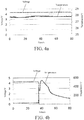
- FIG. 4a is a curve diagram of voltage-temperature versus time for a normal battery obtained using the above battery test method according to an embodiment of this application.
- FIG. 4b is a curve diagram showing voltage-temperature versus time of a defective battery obtained using the battery test method 300 of an embodiment of this application.
- Types of a normal battery and a defective battery shown in FIG. 4a and FIG. 4b are the same as the type of the foregoing three groups of batteries.
- a stainless batten whose shape is square and width is 10 mm was used.
- the pressure apparatus descended at a speed of 15 mm/s to contact the stainless batten, and the pressure apparatus was set to continuously apply, for 80s by means of the stainless batten, a force of 12.6 kN to a part of the battery that was located 3 mm away from the top end of the battery used in FIG. 4a .
- Test parameters for the battery used in FIG. 4b were the same as those used for the battery in FIG. 4a .
- a short circuit occurs at a defect location of the battery, which renders that the voltage decreases and the temperature rises.
- different types of short circuits in the battery cause different voltage and temperature changes. For example, for some defective batteries, after a short circuit occurs in the battery, the voltage directly decreases to approximately 0 V, and the temperature directly linearly rises. However, for some defective batteries, after a short circuit occurs in the defective battery, the voltage decreases firstly, then rebounds, and then decreases again, and the temperature linearly rises twice.
- FIG. 4c is a curve diagram of voltage-temperature versus time for another defective battery obtained using the battery testing method 300 of an embodiment of this application.
- a stainless batten whose shape is square and width is 10 mm was used; the pressure apparatus descended at a speed of 15 mm/s to contact the stainless batten, and the pressure apparatus was set to continuously apply, for 80s by means of the stainless batten, a force of 12.6 kN to a part of the battery that was located 3 mm away from the top end of the battery used in FIG. 4c .
- the battery test method provided in this application, the battery may be tested in a case which is closest to an actual case in which the battery is damaged. Therefore, an inner defect and a risk of the battery are identified when the battery is mechanically damaged.
- defective batteries may be further detected by using test conditions for a normal battery to determine the quality and safety level of the batteries.
Landscapes
- Engineering & Computer Science (AREA)
- Manufacturing & Machinery (AREA)
- Chemical & Material Sciences (AREA)
- Chemical Kinetics & Catalysis (AREA)
- Electrochemistry (AREA)
- General Chemical & Material Sciences (AREA)
- Physics & Mathematics (AREA)
- General Physics & Mathematics (AREA)
- Battery Mounting, Suspending (AREA)
- Secondary Cells (AREA)
Abstract
Description
- The present application claims the benefit of priority from the China Patent Application No.
201811013625.6, filed on 31 August 2018 - This application relates to the field of battery tests, and in particular, to a battery test system and a battery test method.
- Lithium-ion batteries have been widely used in various fields such as electronic products and electric vehicles. In the industry, a UL 1642 (Lithium Batteries) impact test is currently used for testing safety performance of a lithium-ion battery after the lithium-ion battery is rapidly impacted. However, for a soft package battery without housing protection, during the UL 1642 impact test, the soft package battery is usually severely damaged and even broken directly after being impacted. However, such a case in which the soft package battery is severely damaged rarely occurs during actual use of the soft package battery. Therefore, for the soft package battery, the UL 1642 impact test is too strict to objectively reflect the safety performance during actual use of the soft pack battery.
- Therefore, the industry needs a test system and method suitable for the soft package battery.
- One aspect of this application is to provide a battery test system and a battery test method that are applicable to the test of a soft package battery.
- One embodiment of this application provides a battery test system, including: an extrusion apparatus configured to be disposed on a first surface of a battery; and a pressure apparatus disposed above the extrusion apparatus, wherein the pressure apparatus is configured to apply a predetermined force to the battery in predetermined duration through the extrusion apparatus.
- In some embodiments of this application, the pressure apparatus is configured to descend at a predetermined speed to contact the extrusion apparatus.
- In some embodiments of this application, a contact surface of the extrusion apparatus with the first surface of the battery is a substantially flat surface.
- In some embodiments of this application, the extrusion apparatus is a batten, and a longitudinal section shape of the batten is square, triangular, circular, or semi-circular.
- In some embodiments of this application, a side edge of the contact surface of the extrusion apparatus has a chamfer.
- In some embodiments of this application, the chamfer has a radius of a circular arc from about 0.5 mm to about 5 mm.
- In some embodiments of this application, the extrusion apparatus is fastened to the first surface of the battery with glue or a fastening tape.
- In some embodiments of this application, the battery test system further includes a data collection apparatus configured for collecting battery parameters of the battery, the battery parameters including temperatures and voltages of the battery.
- In some embodiments of this application, the battery test system further includes a carrying apparatus, wherein a second surface of the battery is configured to be disposed on the carrying apparatus, and the second surface is opposite to the first surface.
- Another embodiment of this application provides a battery test method, including: disposing an extrusion apparatus on a first surface of a battery; and applying a predetermined force to the extrusion apparatus through a pressure apparatus to squeeze the battery and keep so for a predetermined time.
- In some embodiments of this application, the step of applying a predetermined force to the extrusion apparatus through a pressure apparatus includes: descending the pressure apparatus at a predetermined speed to contact the extrusion apparatus.
- In some embodiments of this application, the predetermined speed ranges from about 0.5 mm/s to about 100 mm/s.
- In some embodiments of this application, the test method further includes: collecting battery parameters of the battery by a data collection apparatus, the battery parameters including temperatures and voltages of the battery.
- In some embodiments of this application, the test method further includes: disposing a second surface of the battery on a carrying apparatus, and the second surface is opposite to the first surface.
- In some embodiments of this application, the step of collecting battery parameters of the battery includes: collecting the battery parameters of the battery after the battery squeezed by the extrusion device is stored at room temperature for the predetermined time.
- In some embodiments of this application, the test method further includes: testing with a normal battery, and determining, by changing the predetermined force and/or the predetermined time, a critical value where battery parameters of the normal battery start to change.
- The battery test system and the battery test method provided in this application are able to reasonably evaluate the safety of the soft package battery and identify the risk caused by the defect of the soft package battery.
- To describe the embodiments of this application, the following briefly describes the accompanying drawings required for describing the embodiments of this application or the prior art. Apparently, the accompanying drawings in the following descriptions are merely some embodiments of this application, and persons skilled in the art may still derive drawings of other embodiments from examples of structures shown in these accompanying drawings without creative efforts.
-
FIG. 1 is a schematic longitudinal cross-sectional view of a battery test system according to an embodiment of this application. -
FIG. 2 is a schematic top view of a part of the battery test system according to the embodiment shown inFIG. 1 . -
FIG. 3 is a schematic flowchart of a battery test method according to an embodiment of this application. -
FIG. 4a is a curve diagram of voltage-temperature versus time for a normal battery obtained using a battery test method according to an embodiment of this application. -
FIG. 4b is a curve diagram showing voltage-temperature versus time of a defective battery obtained using the battery test method of an embodiment of this application. -
FIG. 4c is a curve diagram of voltage-temperature versus time for another defective battery obtained using the battery testing method of an embodiment of this application. - Embodiments of this application are described below in detail. Throughout the entire specification of this application, same or similar components or components having same or similar functions are represented by using similar reference numerals. The embodiments related to the accompanying drawings that are described herein are illustrative and schematic, and are used to provide basic understanding for this application. The embodiments of this application should not be construed as limitations to this application.
- In this specification, unless otherwise particularly indicated or limited, relativistic wordings such as "central", "longitudinal", "lateral", "front", "back", "right", "left", "inner", "outer", "relatively low", "relatively high", "horizontal", "vertical", "higher than", "lower than", "above", "below", "top", "bottom", and derived wordings thereof (such as "horizontally", "downward", and "upward") should be construed as referenced directions described in discussion or shown in the accompanying drawings. These relativistic wordings are merely for ease of description, and require constructing or operating this application in a particular direction.
- As used in this application, terms "about", "roughly", "substantially", "essentially", and "approximately" are used for describing and explaining a small variation. When being used in combination with an event or a case, the terms can refer to an example in which the event or case exactly occurs, or an example in which the event or case similarly occurs. For example, when being used in combination with a value, the terms may refer to a variation range being less than or equal to ±10% of the value, for example, less than or equal to ±5%, less than or equal to ±4%, less than or equal to ±3%, less than or equal to ±2%, less than or equal to ±1%, less than or equal to ±0.5%, less than or equal to ±0.1%, or less than or equal to ±0.05%. For example, if a difference between two values is less than or equal to ± 10% of an average value of the values (for example, less than or equal to ±5%, less than or equal to ±4%, less than or equal to ±3%, less than or equal to ±2%, less than or equal to ±1%, less than or equal to ±0.5%, less than or equal to ±0.1%, or less than or equal to ±0.05%), it could be considered that the two values are "substantially" the same or "approximate".
- Furthermore, for ease of description, the terms "first", "second", "third", and the like may be used for distinguishing between different components in a diagram or a series of diagrams. The terms "first", "second", "third", and the like are not intended to describe corresponding components.
- In this specification, unless otherwise particularly indicated or limited, wordings such as "dispose", "connect", "couple", "fix", and similar wordings thereof are widely used, and a person skilled in the art may understand, based on a specific case, the foregoing wordings as, for example, fixedly connected, detachably connected, or integrally connected, or may be mechanically connected or electronically connected, or may be directly connected or indirectly connected by using an intermediate structure; or may be internal communication between two components.
- In consideration of a case in which during use of a battery in a terminal, the battery may be suddenly impacted or smashed by a heavy object. Therefore, an impact test is added to UL 1642. The UL 1642 impact test is disposing a round bar with a diameter of 15.8 mm ± 0.1 mm at the center of a battery, and then making an iron block with a weight of 9.1 kg ± 0.46 kg freely fall from a height of 610 mm ± 25 mm to impact the battery. A criterion of a qualified battery is no fire and no explosion. However, for the soft package battery, the method for directly impacting the soft package battery by using the heavy object and the round bar is not suitable. A reason lies in that the soft package battery does not have housing protection, so that the soft package battery is usually severely damaged and even is broken directly after being impacted during the UL 1642 impact test. However, during actual use of the soft package battery, the situation in which a housing of the battery is broken or the battery is broken due to an impact rarely occurs. Therefore, in the UL 1642 impact test, the situation that would occur during actual use of the soft package battery is not ideally tested. Consequently, the safety of the battery cannot be appropriately estimated, and a safety risk caused by a defect in the battery cannot be identified.
- Actually, for lithium-ion batteries and various other types of batteries, when the battery is mechanically damaged to an extent, a short circuit may occur within the battery. As a result, the battery generates a large amount of heat within a short time. If the heat keeps gathering, various types of safety accidents such as smoking, leakage, and fire are caused. Therefore, the industry needs a safety test system and method that are able to test the anti-risk capability of the battery after the battery is damaged. Further, in consideration of various types of applications and cases of the battery, the battery in a terminal product is usually protected by an apparatus such as the housing. During actual use, a most possible case is that a press force is indirectly and continuously applied to the battery when a product is squeezed or impacted. Because a defect may occur at a local squeezed part of the battery when a safety test is performed on the battery, if the damaged location can be selected as a location in which a short circuit most easily occurs in the battery, the safety test has sufficient pertinence and applicability, thereby exerting a maximum value for testing a risk of the battery.
- In view of the above situation, this application provides a battery test system. The battery test system includes an extrusion apparatus configured to be disposed on a surface of the battery, and a pressure apparatus disposed above the extrusion apparatus. The pressure apparatus applies a predetermined force to the battery in predetermined duration through the extrusion apparatus, so that a local part of the battery is continuously squeezed to a predetermined extent. The battery test system may simulate a case in which the battery is easily damaged when the battery is used in a terminal system, thereby effectively estimating the safety performance of the battery after being squeezed. If a defect exists in the battery, a short circuit may occur, and even cause a case where leakage, smoking, or fire occurs. Therefore, according to the battery test system provided in this application, the quality and safety level of the battery can be directly determined, thereby identifying an inner defect and a risk of the battery. Preferred embodiments of the battery test system that are provided in this application are described below in detail.
-
FIG. 1 is a schematic longitudinal cross-sectional view of abattery test system 100 according to an embodiment of this application.FIG. 2 is a schematic top view of a part of thebattery test system 100 according to the embodiment shown inFIG. 1 . As shown inFIG. 1 andFIG. 2 , thebattery test system 100 according to an embodiment of this application includes anextrusion apparatus 10, apressure apparatus 12, abattery 14, and a carryingapparatus 16. - The
extrusion apparatus 10 is fastened to afirst surface 141 of thebattery 14 through, for example, but is not limited to, a glue (not shown). In other embodiments of this application, theextrusion apparatus 10 may be alternatively fastened to thefirst surface 141 of thebattery 14 with a fastening tape or any other suitable manner. In the embodiments shown inFIG. 1 andFIG. 2 , theextrusion apparatus 10 may be a batten whose longitudinal section shape is square and width D is approximately 10 mm, and the batten may be made of steel. Acontact surface 101 of theextrusion apparatus 10 with thefirst surface 141 of thebattery 14 is a substantially flat surface. To prevent a side edge of theextrusion apparatus 10 from cutting thebattery 14, the side edge of thecontact surface 101 of theextrusion apparatus 10 is provided with a chamfer (not shown), i.e., the contact surface of theextrusion apparatus 10 with thebattery 14 is an arc surface. In some embodiments, the chamfer has a radius of a circular arc from about 0.5 mm to about 5 mm. - The width, shape, and material of the batten are not limited to those shown in the foregoing embodiments. In other embodiments of this application, the batten is made of any material having suitable hardness, for example, stainless steel. In other embodiments of this application, the width D of the batten whose longitudinal section shape is square may be about 5 mm to about 150 mm. In some embodiments of this application, the
extrusion apparatus 10 may be a batten whose longitudinal section shape is triangular and side length is about 5 mm to about 150 mm. In some embodiments of this application, theextrusion apparatus 10 may be a batten whose longitudinal section shape is circular and diameter is about 5 mm to about 150 mm. In some embodiments of this application, theextrusion apparatus 10 may be a batten whose longitudinal section shape is semi-circular and diameter is about 5 mm to about 150 mm. - In the embodiments shown in
FIG. 1 andFIG. 2 , thepressure apparatus 12 is disposed above theextrusion apparatus 10 and applies a predetermined force to thebattery 14 in predetermined duration through theextrusion apparatus 10. The predetermined force may be set according to a specific battery size. In one embodiment of this application, the predetermined force is about 5 kN to about 200 kN. In some embodiments of this application, the predetermined force is about 5 kN to about 100 kN. In some embodiments of this application, the predetermined duration may be about 1 minute. In some embodiments of this application, the predetermined duration may be any suitable time, and may be determined according to specific demands or battery size. - In one embodiment of this application, the
pressure apparatus 12 is configured to descend at a predetermined speed to contact theextrusion apparatus 10. The predetermined speed is about 0.5 mm/s to about 500 mm/s. In some embodiments of this application, the predetermined speed is about 0.5 mm/s to about 100 mm/s. In some embodiments of this application, thepressure apparatus 12 may be configured to descend at a predetermined constant speed to contact theextrusion apparatus 10. In some embodiments of this application, thepressure apparatus 12 may be configured to descend at a predetermined non-constant speed to contact theextrusion apparatus 10. - A local part of the
battery 14 is continuously squeezed by continuously squeezing theextrusion apparatus 10 through thepressure apparatus 12, thereby properly inspecting thebattery 14. If a defect exists in thebattery 14, a short circuit may occur, and even cause a case where leakage, smoking, or fire may occur. Therefore, the quality and safety level of the battery can be directly determined. After thepressure apparatus 12 continuously squeezes theextrusion apparatus 10, the battery in which no short circuit occurs only shows a certain amount of deformation. In comparison with the UL 1642 impact test, the amount of deformation occurred at a local part of the battery according to the present disclosure is much closer to what a battery protected in a terminal device actually experiences under squeezing. That is, the battery is not broken, but appears squeezing deformation. - The
battery 14 has afirst surface 141 and asecond surface 142 opposite to thefirst surface 141. Thesecond surface 142 is fastened to the carryingapparatus 16 through, for example, but is not limited to, a glue. In other embodiments of this application, thebattery 14 may be alternatively fastened to the carryingapparatus 16 with a fastening tape or any other suitable manner. Thebattery 14 is a soft package battery of any type in the art, for example, but not limited to, a soft package lithium-ion battery. - The carrying
apparatus 16 is used for carrying thebattery 14, and the surface of the carryingapparatus 16 for carrying thesecond surface 142 of thebattery 14 is flat. In one embodiment of this application, the carryingapparatus 16 may be a test bench. - In some embodiments of this application, the
battery test system 100 further includes a data collection apparatus (not shown). The data collection apparatus is used for collecting battery parameters of thebattery 14. The battery parameters include various parameters that can indicate the safety performance of thebattery 14, such as, but are not limited to, temperatures and voltages. When thepressure apparatus 12 is descended at a certain speed to contact theextrusion apparatus 10, a local part of thebattery 14 is impacted initially. During a process in which the force of theextrusion apparatus 10 is continuously applied to thebattery 14, the temperature and the voltage of thebattery 14 may more accurately reflect whether a short circuit occurs in thebattery 14. If a short circuit occurs, the temperature will rise at a certain speed, and the voltage drop will reach a certain value after a certain time. Therefore, a damaged state in thebattery 14 may be more clearly determined by detecting the parameters such as the temperatures and the voltages. -
FIG. 3 is a schematic flowchart of abattery test method 300 according to one embodiment of this application, which uses thebattery test system 100 provided by the embodiments shown inFIGS. 1 and2 of this application. - According to the embodiment shown in
FIG. 3 , instep 301, asurface 101 of anextrusion apparatus 10 is disposed on afirst surface 141 of thebattery 14 by using a glue, a fastening tape, or any other suitable manner (not shown). - In
step 302, a predetermined force is applied to theextrusion apparatus 10 through thepressure apparatus 12 to squeeze thebattery 14 for a predetermined time, wherein the step of applying a predetermined force to theextrusion apparatus 10 through thepressure apparatus 12 includes: descending thepressure apparatus 12 at a predetermined speed to contact theextrusion apparatus 10. The predetermined speed ranges from about 0.5 mm/s to about 500 mm/s. In some embodiments of this application, the predetermined speed is about 0.5 mm/s to about 100 mm/s. In an embodiment of this application, thepressure apparatus 12 is descended at a predetermined constant speed to contact theextrusion apparatus 10. In another embodiment of this application, thepressure apparatus 12 is descended at a predetermined non-constant speed to contact theextrusion apparatus 10. - The
pressure apparatus 12 applies the predetermined force to thebattery 14 through theextrusion apparatus 10 in a predetermined duration. The predetermined force may be set according to a specific battery size. In an embodiment of this application, the predetermined force is about 5 kN to about 200 kN. In some embodiments of this application, the predetermined force is about 5 kN to about 100 kN. In an embodiment of this application, the predetermined duration may be about 1 minute. In some embodiments of this application, the predetermined duration may be any suitable time. A local part of thebattery 14 is continuously squeezed by continuously squeezing theextrusion apparatus 10 through thepressure apparatus 12, thereby properly inspecting thebattery 14. If a defect exists in thebattery 14, a short circuit may occur, and even cause a case where leakage, smoking, or fire may occur. Therefore, according to thebattery test method 300 provided in this application, a defect in the battery can be directly identified. In addition, because various parameters such as the force that is applied by thepressure apparatus 12 to thebattery 14 and the time in which the force is applied may be adjusted, thebattery test method 300 according to the embodiment of this application has good flexibility and pertinence, so that different test conditions may be configured for different types of batteries. Therefore, thebattery test method 300 according to the embodiment of this application is suitable for detecting defects of various types of batteries. - In one embodiment of this application, the
battery test method 300 provided in the embodiment shown inFIG. 3 further includes a step of providing the carryingapparatus 16 for carrying thebattery 14 and fastening thebattery 14 to the carryingapparatus 16 by using a glue, a fastening tape, or any other suitable manner. The carryingapparatus 16 may be any test bench having a flat test surface. - In some embodiments of this application, the
battery test method 300 further includes: providing a data collection apparatus, to enable the data collection apparatus to perform a step of collecting battery parameters of thebattery 14. The battery parameters include various parameters that may indicate the safety performance of thebattery 14, for example, but are not limited to, temperatures and voltages. When thepressure apparatus 12 is descended at a speed to contact theextrusion apparatus 10, a local part of thebattery 14 is impacted initially. During a process in which the force of theextrusion apparatus 10 is continuously applied to thebattery 14, the temperature and the voltage of thebattery 14 may more directly reflect whether a short circuit occurs in thebattery 14. If a short circuit occurs, the temperature will rise at a certain speed, and the voltage drop will reach a certain value. Therefore, a damaged state in thebattery 14 may be more clearly detected by detecting the parameters such as the temperature and the voltage. - In some embodiments of this application, the
battery test method 300 further includes a step of collecting the battery parameters of thebattery 14 after thebattery 14 squeezed by theextrusion apparatus 10 is placed at room temperature for about 24 hours. If a decreased value of an open-circuit voltage (OCV) of the battery is less than about 30 mV after about 24 hours, thebattery 14 is qualified. If a short circuit occurs at a defect location of thebattery 14 after thebattery 14 is squeezed, an obvious voltage drop will occur after about 24 hours. - The
battery test method 300 of this application is applicable to batteries of various designs. In an embodiment of this application, thebattery test method 300 further includes: testing with a normal battery and determining by changing the predetermined force and/or the predetermined time, a critical value where battery parameters of the normal battery start to change, and used to distinguish between a normal battery and a defective battery. For example, when the squeeze time is fixed, a critical force/pressure of the normal battery may be found by changing the squeeze force, so that magnitude value of the predetermined force is determined as a test criterion for distinguishing between a normal battery and a defective battery (for example, batteries with an overly high welding height). Therefore, for batteries of a same type, the defective batteries may be detected by using test conditions of the normal batteries, so as to determine the quality and safety level of the battery. - Three groups of soft package lithium-ion batteries of a same type (type I) were provided. A first group of batteries are 10 batteries known as batteries of normal types. A second group of batteries are also 10 batteries known as batteries of normal types. A third group of batteries are 10 batteries where defects in the batteries are unknown, i.e., the third group of batteries may include a part of normal batteries.
- According to the battery test method in this application, a stainless batten whose shape is square and width is 10 mm was provided. The
pressure apparatus 12 descended at a speed of 15 mm/s to contact the stainless batten, the pressure apparatus was set to continuously apply, for 80s by means of the stainless batten, a force of 12.6 kN to a part of a battery of a normal type that was located 3 mm away from the top end of the battery, and temperature and voltage changes of the tested battery within 80s were measured. In addition, a voltage change of the tested battery was measured again after the tested battery had been stored at room temperature for 24 hours. If the temperature and the voltage of the tested battery did not obviously change within 80s, i.e., the temperature change ranged from approximately 1 degree to approximately 10 degree, and the voltage change ranged from 0 volt to 0.03 volt, and no obvious voltage drop was observed after the tested battery had been stored at room temperature for 24 hours, it may be considered that the battery is qualified. - When other parameters such as a test time remain unchanged, the condition where a battery known as a battery of a normal type became defective was obtained by continuously changing the values of the applied force/pressure. In this way, test parameters for distinguishing between a defective battery and a normal battery may be found.
- Using the above test method to the first group of batteries and the second group of batteries, and the test results were listed in Table 1 below. As seen from Table 1, the first group of batteries are all qualified in a condition in which the force was 12.6 kN and the pressure was 53 MPa, i.e., temperatures and voltages of all the first group of batteries did not obviously change in the 80s squeeze time, and no obvious voltage drop was observed after the batteries had been stored at the room temperature for 24 hours. For the second group of batteries in a condition in which the force was 12.8 kN and the pressure was 54 MPa, one battery is not qualified, the temperature and the voltage of the unqualified battery did not obviously change in the 80s squeeze time, and there was an obvious voltage drop after the unqualified battery had been stored at room temperature for 24 hours. Therefore, the test conditions for the first group of batteries were determined as test criteria for distinguishing between a normal battery and a defective battery.
- Then, according to the battery test method in this application, a same stainless batten whose shape is square and width is about 10 mm was provided. The same pressure apparatus descended at a speed of 15 mm/s, which is the same as the descending speed of the pressure apparatus for the first and the second group of batteries, to contact the stainless batten, the pressure apparatus was set to continuously apply, for 80s by means of the stainless batten, a force of 12.6 kN to a part of each battery in the third group of batteries that was located 3 mm away from the top end of the battery). And the test results of the third group of batteries were also listed in Table 1 below. As seen from Table 1, six batteries having defects are detected in the third group of batteries by using the above method, and other batteries are qualified. It is discovered, through further analysis and detection on six unqualified batteries, that all of the six unqualified batteries have a defect of a too high welding height at the portion of 3 mm away from the top end of the battery.
Table 1 the test results of three groups of batteries Group Force/kN Pressure/MPa Quantity of tested batteries Quantity of qualified batteries First group 12.6 53 10 10 Second group 12.8 54 10 9 Third group 12.6 53 10 4 - The applicant found that, through the experiments, for type-I batteries, defective batteries may be strictly inspected by using the stainless batten whose shape is square and width is 10 mm, descending the pressure apparatus at the speed of 15 mm/s to contact the stainless batten, and continuously applying the force of 12.6 kN to the battery within 80s by means of the batten.
- Now refer to
FIG. 4a and FIG. 4b. FIG. 4a is a curve diagram of voltage-temperature versus time for a normal battery obtained using the above battery test method according to an embodiment of this application.FIG. 4b is a curve diagram showing voltage-temperature versus time of a defective battery obtained using thebattery test method 300 of an embodiment of this application. - Types of a normal battery and a defective battery shown in
FIG. 4a and FIG. 4b are the same as the type of the foregoing three groups of batteries. According to thebattery test method 300 in this application, a stainless batten whose shape is square and width is 10 mm was used. The pressure apparatus descended at a speed of 15 mm/s to contact the stainless batten, and the pressure apparatus was set to continuously apply, for 80s by means of the stainless batten, a force of 12.6 kN to a part of the battery that was located 3 mm away from the top end of the battery used inFIG. 4a . Test parameters for the battery used inFIG. 4b were the same as those used for the battery inFIG. 4a . It may be observed that voltage and temperature changes of the normal battery shown inFIG. 4a are very small. Moreover, no obvious voltage drop was observed after the battery inFIG. 4a had been stored at room temperature for 24 hours. However, the voltage of the defective battery shown inFIG. 4b directly decreased to approximately 0 V when the pressure apparatus applied the force to the battery for about 40s, and the temperature linearly rose twice. - Specifically, if a defect exists in the battery, during a process in which the battery is squeezed, a short circuit occurs at a defect location of the battery, which renders that the voltage decreases and the temperature rises. Moreover, different types of short circuits in the battery cause different voltage and temperature changes. For example, for some defective batteries, after a short circuit occurs in the battery, the voltage directly decreases to approximately 0 V, and the temperature directly linearly rises. However, for some defective batteries, after a short circuit occurs in the defective battery, the voltage decreases firstly, then rebounds, and then decreases again, and the temperature linearly rises twice.
-
FIG. 4c is a curve diagram of voltage-temperature versus time for another defective battery obtained using thebattery testing method 300 of an embodiment of this application. According to thebattery test method 300 in this application, a stainless batten whose shape is square and width is 10 mm was used; the pressure apparatus descended at a speed of 15 mm/s to contact the stainless batten, and the pressure apparatus was set to continuously apply, for 80s by means of the stainless batten, a force of 12.6 kN to a part of the battery that was located 3 mm away from the top end of the battery used inFIG. 4c . After thebattery test method 300 according to the embodiment of this application was used for the defective battery, a short circuit occurs in the defective battery due to continuous squeeze, an obvious voltage drop was caused at a moment when the battery had been squeezed for 20s to 40s, and the temperature also obviously rose. - In addition, even if for some
batteries 14, no obvious voltage drop and temperature rise were found after thesebatteries 14 were squeezed, voltage drops of thebatteries 14 may occur after thebatteries 14 had been stored at room temperature for 24 hours. Therefore, parameters of thebattery 14 during the test and parameters of thebattery 14 after thebattery 14 has been tested for 24 hours are monitored, so that it is doubly ensured that any safety problem with thebattery 14 may be identified. - For the soft package battery without housing protection, squeezing the battery to be completely broken is not the best test method. A case in which a local part of the battery is damaged is more likely to easily occur than a case in which the battery is completely broken. Compared with the UL 1642 impact test, in the battery test method provided in this application, the battery may be tested in a case which is closest to an actual case in which the battery is damaged. Therefore, an inner defect and a risk of the battery are identified when the battery is mechanically damaged. In addition, for batteries of a same type, according to the battery test method provided in this application, defective batteries may be further detected by using test conditions for a normal battery to determine the quality and safety level of the batteries.
- Technical content and technical features of this application are disclosed above. However, persons skilled in the art may still make replacements and modifications based on the teachings and the disclosure of this application without departing from the spirit of this application. Therefore, the protection scope of this application should not be limited to the content disclosed in the embodiments, and should include various replacements and modifications without departing from this application, and is covered by the claims of this patent.
Claims (15)
- A battery test system (100), comprising:an extrusion apparatus (10), configured to be disposed on a first surface (141) of a battery (14); anda pressure apparatus (12) disposed above the extrusion apparatus (10), wherein the pressure apparatus (12) is configured to apply a predetermined force to the battery (14) in predetermined duration through the extrusion apparatus (10).
- The battery test system (100) according to claim 1, wherein the pressure apparatus (12) is configured to descend at a predetermined speed to contact the extrusion apparatus (10).
- The battery test system (100) according to claim 1 or 2, wherein a contact surface (101) of the extrusion apparatus (10) with the first surface (141) of the battery (14) is a flat surface; and wherein the extrusion apparatus (10) is fastened to the first surface (141) of the battery (14) with a glue or a fastening tape.
- The battery test system (100) according to any one of claims 1-3, wherein the extrusion apparatus (10) is a batten, and a longitudinal section shape of the batten is square, triangular, circular, or semi-circular.
- The battery test system (100) according to claim 3 or 4, wherein a side edge of the contact surface (101) of the extrusion apparatus (10) has a chamfer.
- The battery test system (100) according to claim 5, wherein the chamfer has a radius of a circular arc from 0.5 mm to 5 mm.
- The battery test system (100) according to any one of claims 1-6, further comprising a data collection apparatus for collecting battery parameters of the battery (14), wherein the battery parameters comprises temperature and voltage of the battery (14).
- The battery test system (100) according to any one of claims 1-7, further comprising a carrying apparatus (16), wherein a second surface (142) of the battery (14) is configured to be disposed on the carrying apparatus (16), and the second surface (142) is opposite to the first surface (141).
- A battery test method (300), comprising:disposing an extrusion apparatus (10) on a first surface (141) of a battery (14); andapplying a predetermined force to the extrusion apparatus (10) through a pressure apparatus (12) to squeeze the battery (14) and keep so for a predetermined time.
- The battery test method (300) according to claim 9, wherein the step of applying a predetermined force to the extrusion apparatus (10) through a pressure apparatus (12) comprises: descending the pressure apparatus (12) at a predetermined speed to contact the extrusion apparatus (10).
- The battery test method (300) according to claim 9 or 10, wherein the predetermined speed ranges from 0.5 mm/s to 100 mm/s.
- The battery test method (300) according to any one of claims 9-11, further comprising: collecting battery parameters of the battery (14) by a data collection apparatus, wherein the battery parameters comprise temperature and voltage of the battery (14).
- The battery test method (300) according to claim 12, wherein the step of collecting battery parameters of the battery (14) comprises: collecting the battery parameters of the battery (14) after the battery (14) squeezed by the extrusion device (10) is stored at room temperature for the predetermined time.
- The battery test method (300) according to any one of claim 9-13, further comprising: testing with a normal battery, and determining, by changing the predetermined force or the predetermined time, a critical value where battery parameters of the normal battery start to change.
- The battery test method (300) according to any one of claims 9-14, further comprising: disposing a second surface of the battery (14) on a carrying apparatus (16), wherein the second surface (142) is opposite to the first surface (141).
Applications Claiming Priority (1)
| Application Number | Priority Date | Filing Date | Title |
|---|---|---|---|
| CN201811013625.6A CN109061507A (en) | 2018-08-31 | 2018-08-31 | Battery test system and battery testing method |
Publications (2)
| Publication Number | Publication Date |
|---|---|
| EP3618139A1 true EP3618139A1 (en) | 2020-03-04 |
| EP3618139B1 EP3618139B1 (en) | 2023-11-29 |
Family
ID=64759114
Family Applications (1)
| Application Number | Title | Priority Date | Filing Date |
|---|---|---|---|
| EP19180735.3A Active EP3618139B1 (en) | 2018-08-31 | 2019-06-18 | Battery test system and battery test method |
Country Status (3)
| Country | Link |
|---|---|
| US (1) | US11598815B2 (en) |
| EP (1) | EP3618139B1 (en) |
| CN (1) | CN109061507A (en) |
Cited By (1)
| Publication number | Priority date | Publication date | Assignee | Title |
|---|---|---|---|---|
| CN113092268A (en) * | 2021-04-01 | 2021-07-09 | 合肥国轩高科动力能源有限公司 | Soft package battery cell voltage withstand test method |
Families Citing this family (18)
| Publication number | Priority date | Publication date | Assignee | Title |
|---|---|---|---|---|
| CN110763418A (en) * | 2019-10-21 | 2020-02-07 | 中国汽车技术研究中心有限公司 | A method for testing the reliability of the bottom shot of a power battery system |
| CN110907839A (en) * | 2019-11-21 | 2020-03-24 | 宁德新能源科技有限公司 | Battery testing system and battery testing method |
| CN111112148B (en) * | 2019-11-27 | 2022-02-18 | 武汉船用电力推进装置研究所(中国船舶重工集团公司第七一二研究所) | Batch voltage-withstanding screening method for lithium ion batteries |
| CN111077451B (en) * | 2019-11-27 | 2022-05-13 | 武汉船用电力推进装置研究所(中国船舶重工集团公司第七一二研究所) | Lithium ion battery voltage withstanding test method |
| CN110850310B (en) * | 2019-12-20 | 2022-04-15 | 东软睿驰汽车技术(沈阳)有限公司 | Battery safety testing method and device |
| CN115151804B (en) * | 2020-03-10 | 2025-02-18 | 宁德新能源科技有限公司 | Battery bending test system and battery bending test method |
| CN111474484B (en) * | 2020-04-13 | 2020-11-10 | 南京工业大学 | A test method for the safe working window of a lithium ion battery in a squeezed state |
| DE102021115451A1 (en) * | 2021-06-15 | 2022-12-15 | Bayerische Motoren Werke Aktiengesellschaft | Apparatus for compressing at least a portion of an energy storage cell, and system and method for electrical safety testing |
| CN113933724B (en) * | 2021-09-16 | 2025-02-14 | 军事科学院系统工程研究院军事新能源技术研究所 | A metal-air battery safety test system |
| CN114236398B (en) * | 2021-09-18 | 2025-02-14 | 军事科学院系统工程研究院军事新能源技术研究所 | A test system for the safety of hydrogen fuel cell power generation system |
| CN114279824A (en) * | 2021-12-27 | 2022-04-05 | 湖北亿纬动力有限公司 | Battery compression test fixture and test method |
| CN114976309B (en) * | 2022-05-18 | 2025-07-29 | 东风时代(武汉)电池系统有限公司 | Vehicle power battery monitoring method and device |
| CN115343158B (en) * | 2022-08-19 | 2026-02-10 | 万向一二三股份公司 | A method for testing the foreign object tolerance of a pouch battery |
| CN115902650A (en) * | 2022-11-24 | 2023-04-04 | 楚能新能源股份有限公司 | A battery performance testing method |
| CN116879062A (en) * | 2023-07-07 | 2023-10-13 | 岚图汽车科技有限公司 | Bottom supporting test method of power battery |
| CN119805262A (en) * | 2023-10-10 | 2025-04-11 | 中石油深圳新能源研究院有限公司 | A battery micro-short circuit detection method and system |
| CN117686916B (en) * | 2023-12-12 | 2024-08-30 | 中通维易科技服务有限公司 | Laboratory digital management system |
| CN120445833B (en) * | 2025-07-11 | 2025-11-07 | 中国铁塔股份有限公司浙江省分公司 | A pressure resistance testing device and method for lithium batteries used in communication base stations |
Citations (4)
| Publication number | Priority date | Publication date | Assignee | Title |
|---|---|---|---|---|
| EP2071659A2 (en) * | 2007-12-07 | 2009-06-17 | NTT DoCoMo, Inc. | Battery testing device and battery testing method |
| KR20150054372A (en) * | 2013-11-12 | 2015-05-20 | 유한회사 듀오콤 | Battery crush tester and Battery crush test method |
| CN105334106A (en) * | 2015-10-16 | 2016-02-17 | 辰星(天津)自动化设备有限公司 | Extruder used for battery detection |
| CN108267695A (en) * | 2017-12-22 | 2018-07-10 | 深圳瑞隆新能源科技有限公司 | A kind of analysis test method based on pressure lithium battery interior short circuit |
Family Cites Families (18)
| Publication number | Priority date | Publication date | Assignee | Title |
|---|---|---|---|---|
| US5491420A (en) * | 1993-03-01 | 1996-02-13 | Duracell Inc. | Battery tester with stacked thermochromic elements |
| US5729149A (en) * | 1995-09-29 | 1998-03-17 | Motorola, Inc. | Apparatus for holding a testing substrate in a semiconductor wafer tester and method for using the same |
| US6602633B1 (en) * | 1999-09-13 | 2003-08-05 | Hosiden Corporation | Crush type pressure detecting device, rechargeable battery with pressure detecting device, and portable electronic device |
| JP4408058B2 (en) * | 2004-05-14 | 2010-02-03 | パナソニック株式会社 | Battery evaluation device |
| CN100568012C (en) * | 2005-11-10 | 2009-12-09 | 比亚迪股份有限公司 | Method for testing security of battery |
| CN2929737Y (en) * | 2006-06-23 | 2007-08-01 | 万向电动汽车有限公司 | Comprehensive test table for lithium ion cell |
| CN1889293A (en) * | 2006-07-26 | 2007-01-03 | 深圳市邦凯电子有限公司 | High-multiplying power discharge battery and producing method thereof |
| CN102384854A (en) * | 2010-09-02 | 2012-03-21 | 东莞市贝尔试验设备有限公司 | Temperature control type battery extruder |
| AT511065B1 (en) * | 2011-06-09 | 2012-09-15 | Rosendahl Masch Gmbh | METHOD AND DEVICE FOR CHECKING BATTERY PLATE PACKAGES |
| CN104487857B (en) * | 2012-07-27 | 2017-03-08 | 丰田自动车株式会社 | The test for short-circuit method of secondary cell |
| CN203479842U (en) * | 2013-09-10 | 2014-03-12 | 中航锂电(洛阳)有限公司 | Lithium-battery high voltage test equipment and test clamp thereof |
| DE102014204956A1 (en) * | 2014-03-18 | 2015-09-24 | Robert Bosch Gmbh | Method for detecting anomalies in a battery cell and short-circuit sensor |
| CN106207065B (en) * | 2015-04-30 | 2025-04-29 | 深圳市比克动力电池有限公司 | Lithium ion battery tab, manufacturing method and lithium ion battery |
| CN106124998B (en) * | 2016-08-10 | 2018-09-25 | 惠州出入境检验检疫局检验检疫综合技术中心 | A kind of lithium battery interior short circuit test method |
| CN206834238U (en) * | 2016-11-02 | 2018-01-02 | 东莞市华创电源有限公司 | a pole ear |
| CN106711512B (en) * | 2017-02-21 | 2019-03-15 | 山东玉皇新能源科技有限公司 | Manufacturing method of soft pack battery based on device that can measure internal temperature of battery |
| CN107317047B (en) * | 2017-05-31 | 2019-06-21 | 北京北方华创新能源锂电装备技术有限公司 | A kind of lithium battery and its battery core assemble method of double core struetures |
| US10739751B2 (en) * | 2018-06-18 | 2020-08-11 | International Business Machines Corporation | Apparatus for facilitating evaluating rechargeable batteries |
-
2018
- 2018-08-31 CN CN201811013625.6A patent/CN109061507A/en active Pending
- 2018-12-31 US US16/236,879 patent/US11598815B2/en active Active
-
2019
- 2019-06-18 EP EP19180735.3A patent/EP3618139B1/en active Active
Patent Citations (4)
| Publication number | Priority date | Publication date | Assignee | Title |
|---|---|---|---|---|
| EP2071659A2 (en) * | 2007-12-07 | 2009-06-17 | NTT DoCoMo, Inc. | Battery testing device and battery testing method |
| KR20150054372A (en) * | 2013-11-12 | 2015-05-20 | 유한회사 듀오콤 | Battery crush tester and Battery crush test method |
| CN105334106A (en) * | 2015-10-16 | 2016-02-17 | 辰星(天津)自动化设备有限公司 | Extruder used for battery detection |
| CN108267695A (en) * | 2017-12-22 | 2018-07-10 | 深圳瑞隆新能源科技有限公司 | A kind of analysis test method based on pressure lithium battery interior short circuit |
Non-Patent Citations (1)
| Title |
|---|
| "UL Standard for Safety for Lithium Batteries, UL 1642", INTERNET CITATION, 24 June 1999 (1999-06-24), pages 15 - 16, XP002547361, Retrieved from the Internet <URL:http://img1.zyzhan.com/5/20090519/633783482645312500.pdf> [retrieved on 20090929] * |
Cited By (1)
| Publication number | Priority date | Publication date | Assignee | Title |
|---|---|---|---|---|
| CN113092268A (en) * | 2021-04-01 | 2021-07-09 | 合肥国轩高科动力能源有限公司 | Soft package battery cell voltage withstand test method |
Also Published As
| Publication number | Publication date |
|---|---|
| US11598815B2 (en) | 2023-03-07 |
| CN109061507A (en) | 2018-12-21 |
| EP3618139B1 (en) | 2023-11-29 |
| US20200072908A1 (en) | 2020-03-05 |
Similar Documents
| Publication | Publication Date | Title |
|---|---|---|
| US11598815B2 (en) | Battery test system and battery test method | |
| CN105122073B (en) | Battery status decision maker | |
| KR102395248B1 (en) | Apparatus for detecting a defect of battery separator and Detecting method using the same | |
| CN101452057B (en) | Battery testing device and battery testing method | |
| KR102795945B1 (en) | Defective Inspection Device of Pouch-type Battery Cell | |
| KR20060047689A (en) | Battery evaluation device | |
| US9577294B2 (en) | Manufacturing method for secondary battery | |
| JP2010153275A (en) | Method for deciding quality of secondary battery, and method for manufacturing secondary battery | |
| KR102256481B1 (en) | Charging and discharging device for battery cell and inspection system for battery cell comprising the same | |
| KR20210155518A (en) | System for determining a defect of battery cell and method for determining a defect of battery cell using the same | |
| KR20210111076A (en) | A detecting device of welding defect | |
| CN110907839A (en) | Battery testing system and battery testing method | |
| JP2010160055A (en) | Battery inspection method | |
| EP3252914B1 (en) | Apparatus and method for sensing opening of current interrupt device of battery unit | |
| CN219284864U (en) | Battery cell welding part inspection equipment | |
| KR102334691B1 (en) | Deterioration detection apparatus for capacitor | |
| CN108050925A (en) | A kind of polymer soft-package battery battery core thickness monitor system and method | |
| CN220207785U (en) | Electrode and test assembly | |
| US5936419A (en) | Test method and apparatus utilizing reactive charging currents to determine whether a test sample is properly connected | |
| JPH10144360A (en) | Inspecting method and inspecting apparatus for battery pack | |
| EP4120428B1 (en) | Device for inspecting for electrode assembly defects before electrolyte injection and defect inspection method therefor | |
| KR102637308B1 (en) | Method for detecting fault of battery pack and apparatus performing the same | |
| JP3380895B2 (en) | How to prevent defective battery production | |
| KR102238196B1 (en) | Short circuit detection device of battery | |
| CN206177561U (en) | Fine or not detection mechanism of extension spring |
Legal Events
| Date | Code | Title | Description |
|---|---|---|---|
| PUAI | Public reference made under article 153(3) epc to a published international application that has entered the european phase |
Free format text: ORIGINAL CODE: 0009012 |
|
| STAA | Information on the status of an ep patent application or granted ep patent |
Free format text: STATUS: THE APPLICATION HAS BEEN PUBLISHED |
|
| AK | Designated contracting states |
Kind code of ref document: A1 Designated state(s): AL AT BE BG CH CY CZ DE DK EE ES FI FR GB GR HR HU IE IS IT LI LT LU LV MC MK MT NL NO PL PT RO RS SE SI SK SM TR |
|
| AX | Request for extension of the european patent |
Extension state: BA ME |
|
| STAA | Information on the status of an ep patent application or granted ep patent |
Free format text: STATUS: REQUEST FOR EXAMINATION WAS MADE |
|
| 17P | Request for examination filed |
Effective date: 20200817 |
|
| RBV | Designated contracting states (corrected) |
Designated state(s): AL AT BE BG CH CY CZ DE DK EE ES FI FR GB GR HR HU IE IS IT LI LT LU LV MC MK MT NL NO PL PT RO RS SE SI SK SM TR |
|
| REG | Reference to a national code |
Ref country code: DE Ref legal event code: R079 Free format text: PREVIOUS MAIN CLASS: H01M0002020000 Ipc: G01N0003120000 Ref country code: DE Ref legal event code: R079 Ref document number: 602019042215 Country of ref document: DE Free format text: PREVIOUS MAIN CLASS: H01M0002020000 Ipc: G01N0003120000 |
|
| GRAP | Despatch of communication of intention to grant a patent |
Free format text: ORIGINAL CODE: EPIDOSNIGR1 |
|
| STAA | Information on the status of an ep patent application or granted ep patent |
Free format text: STATUS: GRANT OF PATENT IS INTENDED |
|
| RIC1 | Information provided on ipc code assigned before grant |
Ipc: H01M 50/55 20210101ALN20230626BHEP Ipc: H01M 50/103 20210101ALN20230626BHEP Ipc: H01M 10/052 20100101ALN20230626BHEP Ipc: G01R 31/388 20190101ALI20230626BHEP Ipc: H01M 10/48 20060101ALI20230626BHEP Ipc: H01M 10/42 20060101ALI20230626BHEP Ipc: G01R 31/36 20200101ALI20230626BHEP Ipc: G01N 3/12 20060101AFI20230626BHEP |
|
| INTG | Intention to grant announced |
Effective date: 20230726 |
|
| GRAS | Grant fee paid |
Free format text: ORIGINAL CODE: EPIDOSNIGR3 |
|
| GRAA | (expected) grant |
Free format text: ORIGINAL CODE: 0009210 |
|
| STAA | Information on the status of an ep patent application or granted ep patent |
Free format text: STATUS: THE PATENT HAS BEEN GRANTED |
|
| AK | Designated contracting states |
Kind code of ref document: B1 Designated state(s): AL AT BE BG CH CY CZ DE DK EE ES FI FR GB GR HR HU IE IS IT LI LT LU LV MC MK MT NL NO PL PT RO RS SE SI SK SM TR |
|
| REG | Reference to a national code |
Ref country code: GB Ref legal event code: FG4D |
|
| REG | Reference to a national code |
Ref country code: CH Ref legal event code: EP |
|
| REG | Reference to a national code |
Ref country code: DE Ref legal event code: R096 Ref document number: 602019042215 Country of ref document: DE |
|
| REG | Reference to a national code |
Ref country code: IE Ref legal event code: FG4D |
|
| REG | Reference to a national code |
Ref country code: NL Ref legal event code: FP |
|
| REG | Reference to a national code |
Ref country code: LT Ref legal event code: MG9D |
|
| PG25 | Lapsed in a contracting state [announced via postgrant information from national office to epo] |
Ref country code: GR Free format text: LAPSE BECAUSE OF FAILURE TO SUBMIT A TRANSLATION OF THE DESCRIPTION OR TO PAY THE FEE WITHIN THE PRESCRIBED TIME-LIMIT Effective date: 20240301 |
|
| PG25 | Lapsed in a contracting state [announced via postgrant information from national office to epo] |
Ref country code: IS Free format text: LAPSE BECAUSE OF FAILURE TO SUBMIT A TRANSLATION OF THE DESCRIPTION OR TO PAY THE FEE WITHIN THE PRESCRIBED TIME-LIMIT Effective date: 20240329 |
|
| PG25 | Lapsed in a contracting state [announced via postgrant information from national office to epo] |
Ref country code: LT Free format text: LAPSE BECAUSE OF FAILURE TO SUBMIT A TRANSLATION OF THE DESCRIPTION OR TO PAY THE FEE WITHIN THE PRESCRIBED TIME-LIMIT Effective date: 20231129 |
|
| PG25 | Lapsed in a contracting state [announced via postgrant information from national office to epo] |
Ref country code: ES Free format text: LAPSE BECAUSE OF FAILURE TO SUBMIT A TRANSLATION OF THE DESCRIPTION OR TO PAY THE FEE WITHIN THE PRESCRIBED TIME-LIMIT Effective date: 20231129 |
|
| PG25 | Lapsed in a contracting state [announced via postgrant information from national office to epo] |
Ref country code: LT Free format text: LAPSE BECAUSE OF FAILURE TO SUBMIT A TRANSLATION OF THE DESCRIPTION OR TO PAY THE FEE WITHIN THE PRESCRIBED TIME-LIMIT Effective date: 20231129 Ref country code: IS Free format text: LAPSE BECAUSE OF FAILURE TO SUBMIT A TRANSLATION OF THE DESCRIPTION OR TO PAY THE FEE WITHIN THE PRESCRIBED TIME-LIMIT Effective date: 20240329 Ref country code: GR Free format text: LAPSE BECAUSE OF FAILURE TO SUBMIT A TRANSLATION OF THE DESCRIPTION OR TO PAY THE FEE WITHIN THE PRESCRIBED TIME-LIMIT Effective date: 20240301 Ref country code: ES Free format text: LAPSE BECAUSE OF FAILURE TO SUBMIT A TRANSLATION OF THE DESCRIPTION OR TO PAY THE FEE WITHIN THE PRESCRIBED TIME-LIMIT Effective date: 20231129 Ref country code: BG Free format text: LAPSE BECAUSE OF FAILURE TO SUBMIT A TRANSLATION OF THE DESCRIPTION OR TO PAY THE FEE WITHIN THE PRESCRIBED TIME-LIMIT Effective date: 20240229 |
|
| REG | Reference to a national code |
Ref country code: AT Ref legal event code: MK05 Ref document number: 1636594 Country of ref document: AT Kind code of ref document: T Effective date: 20231129 |
|
| PG25 | Lapsed in a contracting state [announced via postgrant information from national office to epo] |
Ref country code: SE Free format text: LAPSE BECAUSE OF FAILURE TO SUBMIT A TRANSLATION OF THE DESCRIPTION OR TO PAY THE FEE WITHIN THE PRESCRIBED TIME-LIMIT Effective date: 20231129 Ref country code: RS Free format text: LAPSE BECAUSE OF FAILURE TO SUBMIT A TRANSLATION OF THE DESCRIPTION OR TO PAY THE FEE WITHIN THE PRESCRIBED TIME-LIMIT Effective date: 20231129 Ref country code: PL Free format text: LAPSE BECAUSE OF FAILURE TO SUBMIT A TRANSLATION OF THE DESCRIPTION OR TO PAY THE FEE WITHIN THE PRESCRIBED TIME-LIMIT Effective date: 20231129 Ref country code: NO Free format text: LAPSE BECAUSE OF FAILURE TO SUBMIT A TRANSLATION OF THE DESCRIPTION OR TO PAY THE FEE WITHIN THE PRESCRIBED TIME-LIMIT Effective date: 20240229 Ref country code: LV Free format text: LAPSE BECAUSE OF FAILURE TO SUBMIT A TRANSLATION OF THE DESCRIPTION OR TO PAY THE FEE WITHIN THE PRESCRIBED TIME-LIMIT Effective date: 20231129 Ref country code: HR Free format text: LAPSE BECAUSE OF FAILURE TO SUBMIT A TRANSLATION OF THE DESCRIPTION OR TO PAY THE FEE WITHIN THE PRESCRIBED TIME-LIMIT Effective date: 20231129 |
|
| P01 | Opt-out of the competence of the unified patent court (upc) registered |
Effective date: 20240430 |
|
| PG25 | Lapsed in a contracting state [announced via postgrant information from national office to epo] |
Ref country code: DK Free format text: LAPSE BECAUSE OF FAILURE TO SUBMIT A TRANSLATION OF THE DESCRIPTION OR TO PAY THE FEE WITHIN THE PRESCRIBED TIME-LIMIT Effective date: 20231129 |
|
| PG25 | Lapsed in a contracting state [announced via postgrant information from national office to epo] |
Ref country code: AT Free format text: LAPSE BECAUSE OF FAILURE TO SUBMIT A TRANSLATION OF THE DESCRIPTION OR TO PAY THE FEE WITHIN THE PRESCRIBED TIME-LIMIT Effective date: 20231129 Ref country code: CZ Free format text: LAPSE BECAUSE OF FAILURE TO SUBMIT A TRANSLATION OF THE DESCRIPTION OR TO PAY THE FEE WITHIN THE PRESCRIBED TIME-LIMIT Effective date: 20231129 |
|
| PG25 | Lapsed in a contracting state [announced via postgrant information from national office to epo] |
Ref country code: SK Free format text: LAPSE BECAUSE OF FAILURE TO SUBMIT A TRANSLATION OF THE DESCRIPTION OR TO PAY THE FEE WITHIN THE PRESCRIBED TIME-LIMIT Effective date: 20231129 |
|
| PG25 | Lapsed in a contracting state [announced via postgrant information from national office to epo] |
Ref country code: SM Free format text: LAPSE BECAUSE OF FAILURE TO SUBMIT A TRANSLATION OF THE DESCRIPTION OR TO PAY THE FEE WITHIN THE PRESCRIBED TIME-LIMIT Effective date: 20231129 Ref country code: SK Free format text: LAPSE BECAUSE OF FAILURE TO SUBMIT A TRANSLATION OF THE DESCRIPTION OR TO PAY THE FEE WITHIN THE PRESCRIBED TIME-LIMIT Effective date: 20231129 Ref country code: RO Free format text: LAPSE BECAUSE OF FAILURE TO SUBMIT A TRANSLATION OF THE DESCRIPTION OR TO PAY THE FEE WITHIN THE PRESCRIBED TIME-LIMIT Effective date: 20231129 Ref country code: IT Free format text: LAPSE BECAUSE OF FAILURE TO SUBMIT A TRANSLATION OF THE DESCRIPTION OR TO PAY THE FEE WITHIN THE PRESCRIBED TIME-LIMIT Effective date: 20231129 Ref country code: EE Free format text: LAPSE BECAUSE OF FAILURE TO SUBMIT A TRANSLATION OF THE DESCRIPTION OR TO PAY THE FEE WITHIN THE PRESCRIBED TIME-LIMIT Effective date: 20231129 Ref country code: DK Free format text: LAPSE BECAUSE OF FAILURE TO SUBMIT A TRANSLATION OF THE DESCRIPTION OR TO PAY THE FEE WITHIN THE PRESCRIBED TIME-LIMIT Effective date: 20231129 Ref country code: CZ Free format text: LAPSE BECAUSE OF FAILURE TO SUBMIT A TRANSLATION OF THE DESCRIPTION OR TO PAY THE FEE WITHIN THE PRESCRIBED TIME-LIMIT Effective date: 20231129 Ref country code: AT Free format text: LAPSE BECAUSE OF FAILURE TO SUBMIT A TRANSLATION OF THE DESCRIPTION OR TO PAY THE FEE WITHIN THE PRESCRIBED TIME-LIMIT Effective date: 20231129 |
|
| PG25 | Lapsed in a contracting state [announced via postgrant information from national office to epo] |
Ref country code: PT Free format text: LAPSE BECAUSE OF FAILURE TO SUBMIT A TRANSLATION OF THE DESCRIPTION OR TO PAY THE FEE WITHIN THE PRESCRIBED TIME-LIMIT Effective date: 20240401 |
|
| PG25 | Lapsed in a contracting state [announced via postgrant information from national office to epo] |
Ref country code: PT Free format text: LAPSE BECAUSE OF FAILURE TO SUBMIT A TRANSLATION OF THE DESCRIPTION OR TO PAY THE FEE WITHIN THE PRESCRIBED TIME-LIMIT Effective date: 20240401 |
|
| REG | Reference to a national code |
Ref country code: DE Ref legal event code: R097 Ref document number: 602019042215 Country of ref document: DE |
|
| PLBE | No opposition filed within time limit |
Free format text: ORIGINAL CODE: 0009261 |
|
| STAA | Information on the status of an ep patent application or granted ep patent |
Free format text: STATUS: NO OPPOSITION FILED WITHIN TIME LIMIT |
|
| PG25 | Lapsed in a contracting state [announced via postgrant information from national office to epo] |
Ref country code: SI Free format text: LAPSE BECAUSE OF FAILURE TO SUBMIT A TRANSLATION OF THE DESCRIPTION OR TO PAY THE FEE WITHIN THE PRESCRIBED TIME-LIMIT Effective date: 20231129 |
|
| PG25 | Lapsed in a contracting state [announced via postgrant information from national office to epo] |
Ref country code: SI Free format text: LAPSE BECAUSE OF FAILURE TO SUBMIT A TRANSLATION OF THE DESCRIPTION OR TO PAY THE FEE WITHIN THE PRESCRIBED TIME-LIMIT Effective date: 20231129 |
|
| 26N | No opposition filed |
Effective date: 20240830 |
|
| PG25 | Lapsed in a contracting state [announced via postgrant information from national office to epo] |
Ref country code: MC Free format text: LAPSE BECAUSE OF FAILURE TO SUBMIT A TRANSLATION OF THE DESCRIPTION OR TO PAY THE FEE WITHIN THE PRESCRIBED TIME-LIMIT Effective date: 20231129 |
|
| REG | Reference to a national code |
Ref country code: CH Ref legal event code: PL |
|
| PG25 | Lapsed in a contracting state [announced via postgrant information from national office to epo] |
Ref country code: LU Free format text: LAPSE BECAUSE OF NON-PAYMENT OF DUE FEES Effective date: 20240618 |
|
| PG25 | Lapsed in a contracting state [announced via postgrant information from national office to epo] |
Ref country code: IE Free format text: LAPSE BECAUSE OF NON-PAYMENT OF DUE FEES Effective date: 20240618 |
|
| PG25 | Lapsed in a contracting state [announced via postgrant information from national office to epo] |
Ref country code: BE Free format text: LAPSE BECAUSE OF NON-PAYMENT OF DUE FEES Effective date: 20240630 Ref country code: CH Free format text: LAPSE BECAUSE OF NON-PAYMENT OF DUE FEES Effective date: 20240630 |
|
| REG | Reference to a national code |
Ref country code: BE Ref legal event code: MM Effective date: 20240630 |
|
| PGFP | Annual fee paid to national office [announced via postgrant information from national office to epo] |
Ref country code: NL Payment date: 20250409 Year of fee payment: 7 |
|
| PGFP | Annual fee paid to national office [announced via postgrant information from national office to epo] |
Ref country code: DE Payment date: 20250402 Year of fee payment: 7 |
|
| PGFP | Annual fee paid to national office [announced via postgrant information from national office to epo] |
Ref country code: GB Payment date: 20250401 Year of fee payment: 7 |
|
| PGFP | Annual fee paid to national office [announced via postgrant information from national office to epo] |
Ref country code: FR Payment date: 20250409 Year of fee payment: 7 |
|
| PG25 | Lapsed in a contracting state [announced via postgrant information from national office to epo] |
Ref country code: FI Free format text: LAPSE BECAUSE OF FAILURE TO SUBMIT A TRANSLATION OF THE DESCRIPTION OR TO PAY THE FEE WITHIN THE PRESCRIBED TIME-LIMIT Effective date: 20231129 |
|
| PG25 | Lapsed in a contracting state [announced via postgrant information from national office to epo] |
Ref country code: CY Free format text: LAPSE BECAUSE OF FAILURE TO SUBMIT A TRANSLATION OF THE DESCRIPTION OR TO PAY THE FEE WITHIN THE PRESCRIBED TIME-LIMIT; INVALID AB INITIO Effective date: 20190618 |
|
| PG25 | Lapsed in a contracting state [announced via postgrant information from national office to epo] |
Ref country code: HU Free format text: LAPSE BECAUSE OF FAILURE TO SUBMIT A TRANSLATION OF THE DESCRIPTION OR TO PAY THE FEE WITHIN THE PRESCRIBED TIME-LIMIT; INVALID AB INITIO Effective date: 20190618 |