EP3618033A1 - System and method for controlling traffic lights - Google Patents
System and method for controlling traffic lights Download PDFInfo
- Publication number
- EP3618033A1 EP3618033A1 EP19191670.9A EP19191670A EP3618033A1 EP 3618033 A1 EP3618033 A1 EP 3618033A1 EP 19191670 A EP19191670 A EP 19191670A EP 3618033 A1 EP3618033 A1 EP 3618033A1
- Authority
- EP
- European Patent Office
- Prior art keywords
- radar
- surrounding environment
- environment information
- information
- traffic
- Prior art date
- Legal status (The legal status is an assumption and is not a legal conclusion. Google has not performed a legal analysis and makes no representation as to the accuracy of the status listed.)
- Withdrawn
Links
Images



Classifications
-
- G—PHYSICS
- G08—SIGNALLING
- G08G—TRAFFIC CONTROL SYSTEMS
- G08G1/00—Traffic control systems for road vehicles
- G08G1/07—Controlling traffic signals
-
- G—PHYSICS
- G08—SIGNALLING
- G08G—TRAFFIC CONTROL SYSTEMS
- G08G1/00—Traffic control systems for road vehicles
- G08G1/09—Arrangements for giving variable traffic instructions
- G08G1/095—Traffic lights
-
- G—PHYSICS
- G08—SIGNALLING
- G08G—TRAFFIC CONTROL SYSTEMS
- G08G1/00—Traffic control systems for road vehicles
- G08G1/07—Controlling traffic signals
- G08G1/08—Controlling traffic signals according to detected number or speed of vehicles
-
- G—PHYSICS
- G01—MEASURING; TESTING
- G01S—RADIO DIRECTION-FINDING; RADIO NAVIGATION; DETERMINING DISTANCE OR VELOCITY BY USE OF RADIO WAVES; LOCATING OR PRESENCE-DETECTING BY USE OF THE REFLECTION OR RERADIATION OF RADIO WAVES; ANALOGOUS ARRANGEMENTS USING OTHER WAVES
- G01S17/00—Systems using the reflection or reradiation of electromagnetic waves other than radio waves, e.g. lidar systems
- G01S17/87—Combinations of systems using electromagnetic waves other than radio waves
-
- G—PHYSICS
- G01—MEASURING; TESTING
- G01S—RADIO DIRECTION-FINDING; RADIO NAVIGATION; DETERMINING DISTANCE OR VELOCITY BY USE OF RADIO WAVES; LOCATING OR PRESENCE-DETECTING BY USE OF THE REFLECTION OR RERADIATION OF RADIO WAVES; ANALOGOUS ARRANGEMENTS USING OTHER WAVES
- G01S17/00—Systems using the reflection or reradiation of electromagnetic waves other than radio waves, e.g. lidar systems
- G01S17/88—Lidar systems specially adapted for specific applications
-
- G—PHYSICS
- G05—CONTROLLING; REGULATING
- G05D—SYSTEMS FOR CONTROLLING OR REGULATING NON-ELECTRIC VARIABLES
- G05D1/00—Control of position, course, altitude or attitude of land, water, air or space vehicles, e.g. using automatic pilots
- G05D1/02—Control of position or course in two dimensions
- G05D1/021—Control of position or course in two dimensions specially adapted to land vehicles
- G05D1/0231—Control of position or course in two dimensions specially adapted to land vehicles using optical position detecting means
-
- G—PHYSICS
- G05—CONTROLLING; REGULATING
- G05D—SYSTEMS FOR CONTROLLING OR REGULATING NON-ELECTRIC VARIABLES
- G05D1/00—Control of position, course, altitude or attitude of land, water, air or space vehicles, e.g. using automatic pilots
- G05D1/02—Control of position or course in two dimensions
- G05D1/021—Control of position or course in two dimensions specially adapted to land vehicles
- G05D1/0257—Control of position or course in two dimensions specially adapted to land vehicles using a radar
-
- G—PHYSICS
- G06—COMPUTING OR CALCULATING; COUNTING
- G06V—IMAGE OR VIDEO RECOGNITION OR UNDERSTANDING
- G06V20/00—Scenes; Scene-specific elements
- G06V20/50—Context or environment of the image
- G06V20/56—Context or environment of the image exterior to a vehicle by using sensors mounted on the vehicle
- G06V20/58—Recognition of moving objects or obstacles, e.g. vehicles or pedestrians; Recognition of traffic objects, e.g. traffic signs, traffic lights or roads
- G06V20/584—Recognition of moving objects or obstacles, e.g. vehicles or pedestrians; Recognition of traffic objects, e.g. traffic signs, traffic lights or roads of vehicle lights or traffic lights
-
- G—PHYSICS
- G08—SIGNALLING
- G08G—TRAFFIC CONTROL SYSTEMS
- G08G1/00—Traffic control systems for road vehicles
- G08G1/01—Detecting movement of traffic to be counted or controlled
- G08G1/0104—Measuring and analyzing of parameters relative to traffic conditions
- G08G1/0108—Measuring and analyzing of parameters relative to traffic conditions based on the source of data
- G08G1/0112—Measuring and analyzing of parameters relative to traffic conditions based on the source of data from the vehicle, e.g. floating car data [FCD]
-
- G—PHYSICS
- G08—SIGNALLING
- G08G—TRAFFIC CONTROL SYSTEMS
- G08G1/00—Traffic control systems for road vehicles
- G08G1/01—Detecting movement of traffic to be counted or controlled
- G08G1/0104—Measuring and analyzing of parameters relative to traffic conditions
- G08G1/0108—Measuring and analyzing of parameters relative to traffic conditions based on the source of data
- G08G1/0116—Measuring and analyzing of parameters relative to traffic conditions based on the source of data from roadside infrastructure, e.g. beacons
-
- G—PHYSICS
- G08—SIGNALLING
- G08G—TRAFFIC CONTROL SYSTEMS
- G08G1/00—Traffic control systems for road vehicles
- G08G1/01—Detecting movement of traffic to be counted or controlled
- G08G1/0104—Measuring and analyzing of parameters relative to traffic conditions
- G08G1/0137—Measuring and analyzing of parameters relative to traffic conditions for specific applications
- G08G1/0145—Measuring and analyzing of parameters relative to traffic conditions for specific applications for active traffic flow control
-
- G—PHYSICS
- G08—SIGNALLING
- G08G—TRAFFIC CONTROL SYSTEMS
- G08G1/00—Traffic control systems for road vehicles
- G08G1/01—Detecting movement of traffic to be counted or controlled
- G08G1/04—Detecting movement of traffic to be counted or controlled using optical or ultrasonic detectors
-
- G—PHYSICS
- G08—SIGNALLING
- G08G—TRAFFIC CONTROL SYSTEMS
- G08G1/00—Traffic control systems for road vehicles
- G08G1/09—Arrangements for giving variable traffic instructions
-
- G—PHYSICS
- G08—SIGNALLING
- G08G—TRAFFIC CONTROL SYSTEMS
- G08G1/00—Traffic control systems for road vehicles
- G08G1/09—Arrangements for giving variable traffic instructions
- G08G1/0962—Arrangements for giving variable traffic instructions having an indicator mounted inside the vehicle, e.g. giving voice messages
- G08G1/0967—Systems involving transmission of highway information, e.g. weather, speed limits
- G08G1/096708—Systems involving transmission of highway information, e.g. weather, speed limits where the received information might be used to generate an automatic action on the vehicle control
- G08G1/096725—Systems involving transmission of highway information, e.g. weather, speed limits where the received information might be used to generate an automatic action on the vehicle control where the received information generates an automatic action on the vehicle control
-
- G—PHYSICS
- G08—SIGNALLING
- G08G—TRAFFIC CONTROL SYSTEMS
- G08G1/00—Traffic control systems for road vehicles
- G08G1/09—Arrangements for giving variable traffic instructions
- G08G1/0962—Arrangements for giving variable traffic instructions having an indicator mounted inside the vehicle, e.g. giving voice messages
- G08G1/0967—Systems involving transmission of highway information, e.g. weather, speed limits
- G08G1/096766—Systems involving transmission of highway information, e.g. weather, speed limits where the system is characterised by the origin of the information transmission
- G08G1/096783—Systems involving transmission of highway information, e.g. weather, speed limits where the system is characterised by the origin of the information transmission where the origin of the information is a roadside individual element
-
- H—ELECTRICITY
- H04—ELECTRIC COMMUNICATION TECHNIQUE
- H04N—PICTORIAL COMMUNICATION, e.g. TELEVISION
- H04N23/00—Cameras or camera modules comprising electronic image sensors; Control thereof
- H04N23/50—Constructional details
- H04N23/54—Mounting of pick-up tubes, electronic image sensors, deviation or focusing coils
Definitions
- the present disclosure relates to the field of traffic technologies, and more particularly to a system and a method for controlling traffic lights.
- the traffic signal light is usually controlled in a predetermined time cycle, that is, durations of a green light, a yellow light and a red light are fixed according to a statistical result of historical traffic flows.
- the traffic flow for example at a same intersection, may changes greatly in different time periods. Therefore, the fixed traffic light durations cannot meet requirements of the complex changes in the traffic flow.
- the existing method for controlling traffic lights lacks flexibility.
- Embodiments of the present disclosure seek to solve at least one of the problems existing in the related art to at least some extent.
- an object of the present disclosure is to provide a system for controlling traffic lights.
- Such a system may acquire the traffic flow information of a road junction via a smart roadside device and flexibly adjust durations of the traffic lights at the road junction according to the traffic flow information, thus improving traffic efficiency and reducing congestion at the road junction.
- Another object of the present disclosure is to provide a method for controlling traffic lights.
- a further object of the present disclosure is to provide a non-temporary computer-readable storage medium.
- a further object of the present disclosure is to provide a program product.
- a system for controlling traffic lights including: a traffic light device, and a smart roadside device, including: a roadside sensing module including: a camera assembly configured to collect information of an image for traffic lights of the traffic light device, and a radar configured to acquire first surrounding environment information of a road junction monitored by the smart roadside device, and a roadside processing module, configured to: determine traffic flow information of a red light lane according to the first surrounding environment information and the information of the image for the traffic lights, determine a duration of a green light according to the traffic flow information, and control a duration displaying the green light in a next cycle of the traffic light device according to the duration of the green light.
- a roadside sensing module including: a camera assembly configured to collect information of an image for traffic lights of the traffic light device, and a radar configured to acquire first surrounding environment information of a road junction monitored by the smart roadside device
- a roadside processing module configured to: determine traffic flow information of a red light lane according to the first surrounding environment information and the information of the image for the
- the system further includes an autonomous vehicle configured to acquire second surrounding environment information around the autonomous vehicle.
- the smart roadside device further comprises a roadside communication module, in which the roadside processing module is further configured to send the first surrounding environment information to the autonomous vehicle via the roadside communication module; and the autonomous vehicle is configured to merge the first surrounding environment information with the second surrounding environment information, and control a driving behavior according to merged surrounding environment information.
- the autonomous vehicle is further configured to send the second surrounding environment information to the smart roadside device; and the roadside processing module is further configured to merge the first surrounding environment information with the second surrounding environment information.
- the radar includes a first radar configured to detect surrounding environment information within a detection coverage of the first radar, and a second radar configured to detect surrounding environment information within a detection coverage of the second radar, in which a detection distance of the first radar is greater than a detection distance of the second radar.
- the first radar and the second radar are both laser radars.
- the first radar is a 64-line laser radar and the second radar is a 16-line laser radar.
- the first radar is a laser radar and the second radar is a millimeter wave radar.
- the first radar is located above the camera assembly, and the second radar is located below the camera assembly.
- the system further includes a shielding layer covering at least part of the camera assembly.
- the traffic flow information of the road junction may be acquired by the smart roadside device and durations of the traffic lights at the road junction may be flexibly adjusted according to the traffic flow information, thus improving traffic efficiency and reducing congestion at the road junction.
- a method for controlling traffic lights including: collecting information of an image for traffic lights of a traffic light device via a camera assembly; acquiring, via a radar, first surrounding environment information of a road junction monitored by a smart roadside device; determining traffic flow information of a current red light lane according to the first surrounding environment information and the information of the image for the traffic lights; and determining a duration of a green light according to the traffic flow information, and controlling a duration displaying the green light in a next cycle of the traffic light device according to the duration of the green light.
- the method further includes sending the first surrounding environment information to an autonomous vehicle via a roadside communication module.
- the method further includes receiving second surrounding environment information sent by the autonomous vehicle, and merging the first surrounding environment information with the second surrounding environment information.
- the traffic flow information of the road junction may be acquired by the smart roadside device and durations of the traffic lights at the road junction may be flexibly adjusted according to the traffic flow information, thus improving traffic efficiency and reducing congestion at the road junction.
- a non-temporary computer-readable storage medium having stored therein computer programs that, when executed by a processor, cause the processor to perform a method for controlling traffic lights as described in above embodiments.
- a program product having stored therein instructions that, when executed by a processor of a device, causes the device to perform a method for controlling traffic lights as described in above embodiments.
- traffic light device 1 smart roadside device 2, autonomous vehicle 3, roadside sensing module 20, roadside processing module 30, roadside communication module 40, camera assembly 210, radar 220, first radar 221, second radar 222.
- Fig. 1 is a block diagram showing a structure of a system for controlling traffic lights according to an embodiment of the present disclosure.
- the system for controlling traffic lights includes a traffic light device 1 and a smart roadside device 2.
- the smart roadside device 2 includes a roadside sensing module 20 and a roadside processing module 30.
- the roadside sensing module 20 includes a camera assembly 210 configured to collect information of an image for traffic lights of the traffic light device 1, and a radar 220 configured to acquire first surrounding environment information of a road junction monitored by the smart roadside device 2.
- the roadside processing module 30 is configured to determine traffic flow information of a red light lane according to the first surrounding environment information and the information of the image for the traffic lights, determine a duration of a green light according to the traffic flow information, and control a duration displaying the green light in a next cycle of the traffic light device 1 according to the duration of the green light.
- the traffic flow information includes, but is not limited to, an amount of vehicles, a type and a length of a vehicle.
- the positional relationship between the traffic light device 1 and the smart roadside device 2 may be set differently.
- the smart roadside device 2 may be arranged near the road junction where the traffic light device 1 is positioned.
- the smart roadside device 2 is communicated with the traffic light device 1, for example in a wireless manner.
- the smart roadside device 2 may determine the traffic flow information of the red light lane according to the environment information at the road junction, determine the duration of the green light according to the traffic flow information, and adjusting the duration displaying the green light in a next cycle of the traffic light device 1 as the duration of the green light. Therefore, a duration in which a traffic light, for example a green light or a red light, is turned on or displayed, may be dynamically adjusted according to the traffic flow information at the road junction.
- the traffic flow information of the road junction may be acquired by the smart roadside device 2 and durations of the traffic lights at the road junction may be flexibly adjusted according to the traffic flow information, thus improving traffic efficiency and reducing congestion at the road junction.
- an autonomous vehicle 3 has a relative small sensing range and is easily obstructed, and an in-vehicle camera may be influenced by a high beam from a vehicle driving towards the autonomous vehicle 3.
- the system is further included with the autonomous vehicle 3, and the smart roadside device 2 further includes a roadside communication module 40 as shown in Fig. 2 .
- the autonomous vehicle 3 is configured to acquire second surrounding environment information around the autonomous vehicle 3.
- the roadside processing module 30 is further configured to send the first surrounding environment information to the autonomous vehicle 3 via the roadside communication module 40.
- the autonomous vehicle 3 is further configured to merge the first surrounding environment information with second surrounding environment information, and control a driving behavior according to merged surrounding environment information.
- the autonomous vehicle 3 may receive the surrounding environment information sensed by the smart roadside device 2, and merge the surrounding environment information which is sensed by itself with the received surrounding environment information to acquire final surrounding environment information, and make a strategy of an automatic driving behavior according to the final surrounding environment information. On this basis, a zone which cannot be detected by the autonomous vehicle 3 may be supplemented by the surrounding environment information collected by the smart roadside device 2, thus improving driving safety of the autonomous vehicle 3.
- the roadside processing module 30 is further configured to send at least one of time and duration displaying the green light to the autonomous vehicle 3.
- the autonomous vehicle 3 may determine the driving behavior, which is in accordance with the traffic rules, based on at least one of the time and duration displaying the green light, and the surrounding environment information, thus improving the driving safety of the autonomous vehicle 3.
- the autonomous vehicle 3 is further configured to send the second surrounding environment information to the smart roadside device 2, and the roadside processing module 30 is further configured to merge the first surrounding environment information with the second surrounding environment information.
- the smart roadside device 2 may merge the surrounding environment information of the road junction sensed by itself with the surrounding environment information sensed by the autonomous vehicle 3, to acquire more accurate environment information, thus further improving the accuracy of the traffic flow information determined by the smart roadside device 2.
- the radar 220 includes a first radar 221 and a second radar 222.
- the first and second radar 221, 222 may be applied for acquiring the surrounding environment information, for example of a target vehicle, more accurately.
- the first radar 221 is configured to detect surrounding environment information within a detection coverage of the first radar 221
- the second radar 222 is configured to detect surrounding environment information within a detection coverage of the second radar 222.
- a detection distance of the first radar 221 is greater than a detection distance of the second radar 222.
- the roadside processing module 30 is further configured to determine information of obstacles near the target vehicle and obstacles far from the target vehicle according to the surrounding environment information detected by the first radar 221, the surrounding environment information detected by the second radar 222 and the image information collected by the camera assembly 210.
- the first radar 221 and the second radar 222 may accurately acquire the surrounding environment information for a relative long distant and for a relative short distance, respectively.
- the roadside processing module 30 may determine the information of obstacles near and far from the target vehicle according to the surrounding environment information detected by the first radar 221 and the second radar 222.
- the type of the first radar 221 and the second radar 222 may be determined to be the same or different from each other.
- the first radar 221 and the second radar 222 are both laser radars.
- the first radar 221 is a 64-line laser radar and the second radar 222 is a 16-line laser radar.
- the smart roadside device 2 may be provided with one 64-line laser radar and several (for example three or four) 16-line laser radars.
- the first radar 221 is a laser radar and the second radar 222 is a millimeter wave radar.
- the first radar 221 is a laser radar and the second radar 222 is a microwave radar.
- first radar 221, the second radar 222 and the camera assembly 210 may be positioned differently.
- first radar 221 is located above the camera assembly 210
- second radar 222 is located below the camera assembly 210.
- one or more camera assemblies 210 may be provided.
- the image for the traffic lights captured by the camera assembly 210 may include information of the road junction where the traffic lights are positioned.
- a shielding layer may cover at least part of the camera assembly 210, so as to reduce the interference caused by the radar 220, thus increasing the imaging clarity of the camera assembly 210 and improving the reliability of roadside smart device 2.
- the shielding layer does not cover camera lenses and heat dissipation components of the camera assembly 210, in other words, the shielding layer covers components other than the lenses and the heat dissipation components of the camera assembly 210, so as to reduce the interference caused by the radar 220, thus increasing the imaging clarity of the camera assembly 210 and improving the reliability of roadside smart device 2.
- a method for controlling traffic lights is provided. Such a method may be performed by the system for controlling traffic lights described above, which is not described in details herein again.
- Fig. 4 is a flow chart of a method for controlling traffic lights according to an embodiment of the present disclosure.
- the method for controlling traffic lights includes following steps.
- first surrounding environment information of the road junction monitored by a smart roadside device is acquired via a radar.
- traffic flow information of a current red light lane is determined according to the first surrounding environment information and the information of the image for the traffic lights.
- a duration of a green light is determined according to the traffic flow information, and a duration displaying the green light in a next cycle of the traffic light device is controlled according to the duration of the green light.
- the traffic flow information of the road junction may be acquired by the smart roadside device and durations of the traffic lights at the road junction may be flexibly adjusted according to the traffic flow information, thus improving traffic efficiency and reducing congestion at the road junction.
- an autonomous vehicle has a relative small sensing range and is easily obstructed, and an in-vehicle camera may be influenced by a high beam from a vehicle driving towards the autonomous vehicle.
- the method includes a further step.
- the first surrounding environment information is sent to an autonomous vehicle via a roadside communication module.
- the autonomous vehicle receives the first surrounding environment information from the smart roadside device, merges the first surrounding environment information with second surrounding environment information sensed by the vehicle itself, and controls a driving behavior according to merged surrounding environment information.
- the method further includes following steps as shown in Fig. 6 .
- the first surrounding environment information is merged with the second surrounding environment information.
- a non-temporary computer-readable storage medium having stored therein computer programs that, when executed by a processor, cause the processor to perform a method for controlling traffic lights as described above.
- a computer program product having stored therein instructions that, when executed by a processor of a device, cause the device to perform a method for controlling traffic lights as described above.
- first and second are used herein for purposes of description and are not intended to indicate or imply relative importance or significance.
- the feature defined with “first” and “second” may include one or more this feature.
- a plurality of' means two or more than two, for example, two or three.
- the terms “mounted”, “connected”, “coupled” and “fixed” and the like are used broadly, and may be, for example, fixed connections, detachable connections, or integral connections; may also be mechanical or electrical connections; may also be direct connections or indirect connections via intervening structures; may also be inner communications of two elements, which can be understood by those skilled in the art according to specific situations.
- a structure in which a first feature is "on" or “below” a second feature may include an embodiment in which the first feature is in direct contact with the second feature, and may also include an embodiment in which the first feature and the second feature are not in direct contact with each other, but are contacted via an additional feature formed therebetween.
- a first feature "on,” “above,” or “on top of' a second feature may include an embodiment in which the first feature is right or obliquely “on,” “above,” or “on top of' the second feature, or just means that the first feature is at a height higher than that of the second feature; while a first feature "below,” “under,” or “on bottom of' a second feature may include an embodiment in which the first feature is right or obliquely “below,” “under,” or “on bottom of' the second feature, or just means that the first feature is at a height lower than that of the second feature.
- Any process or method described in a flow chart or described herein in other ways may be understood to include one or more modules, segments or portions of codes of executable instructions for achieving specific logical functions or steps in the process, and the scope of a preferred embodiment of the present disclosure includes other implementations, in which the order of execution is different from what is shown or discussed, including executing functions in a substantially simultaneous manner or in an opposite order according to the related functions.
- the logic and/or step described in other manners herein or shown in the flow chart, for example, a particular sequence table of executable instructions for realizing the logical function may be specifically achieved in any computer readable medium to be used by the instruction execution system, device or equipment (such as the system based on computers, the system including processors or other systems capable of obtaining the instruction from the instruction execution system, device and equipment and executing the instruction), or to be used in combination with the instruction execution system, device and equipment.
- the computer readable medium may be any device adaptive for including, storing, communicating, propagating or transferring programs to be used by or in combination with the instruction execution system, device or equipment.
- the computer readable medium include but are not limited to: an electronic connection (an electronic device) with one or more wires, a portable computer enclosure (a magnetic device), a random access memory (RAM), a read only memory (ROM), an erasable programmable read-only memory (EPROM or a flash memory), an optical fiber device and a portable compact disk read-only memory (CDROM).
- the computer readable medium may even be a paper or other appropriate medium capable of printing programs thereon, this is because, for example, the paper or other appropriate medium may be optically scanned and then edited, decrypted or processed with other appropriate methods when necessary to obtain the programs in an electric manner, and then the programs may be stored in the computer memories.
- each part of the present disclosure may be realized by the hardware, software, firmware or their combination.
- a plurality of steps or methods may be realized by the software or firmware stored in the memory and executed by the appropriate instruction execution system.
- the steps or methods may be realized by one or a combination of the following techniques known in the art: a discrete logic circuit having a logic gate circuit for realizing a logic function of a data signal, an application-specific integrated circuit having an appropriate combination logic gate circuit, a programmable gate array (PGA), a field programmable gate array (FPGA), etc
- each functional unit in the present disclosure may be integrated in one progressing module, or each functional unit exists as an independent unit, or two or more functional units may be integrated in one module.
- the integrated module can be embodied in hardware, or software. If the integrated module is embodied in software and sold or used as an independent product, it can be stored in the computer readable storage medium.
- the computer readable storage medium may be, but is not limited to, read-only memories, magnetic disks, or optical disks.
Landscapes
- Physics & Mathematics (AREA)
- General Physics & Mathematics (AREA)
- Engineering & Computer Science (AREA)
- Remote Sensing (AREA)
- Radar, Positioning & Navigation (AREA)
- Electromagnetism (AREA)
- Chemical & Material Sciences (AREA)
- Analytical Chemistry (AREA)
- Aviation & Aerospace Engineering (AREA)
- Computer Networks & Wireless Communication (AREA)
- Automation & Control Theory (AREA)
- Atmospheric Sciences (AREA)
- Multimedia (AREA)
- Life Sciences & Earth Sciences (AREA)
- Signal Processing (AREA)
- Theoretical Computer Science (AREA)
- Traffic Control Systems (AREA)
Abstract
Description
- The present disclosure relates to the field of traffic technologies, and more particularly to a system and a method for controlling traffic lights.
- In the present traffic system, the traffic signal light is usually controlled in a predetermined time cycle, that is, durations of a green light, a yellow light and a red light are fixed according to a statistical result of historical traffic flows.
- However, as the traffic situation becomes more and more complex nowadays, the traffic flow, for example at a same intersection, may changes greatly in different time periods. Therefore, the fixed traffic light durations cannot meet requirements of the complex changes in the traffic flow. The existing method for controlling traffic lights lacks flexibility.
- Embodiments of the present disclosure seek to solve at least one of the problems existing in the related art to at least some extent.
- Accordingly, an object of the present disclosure is to provide a system for controlling traffic lights. Such a system may acquire the traffic flow information of a road junction via a smart roadside device and flexibly adjust durations of the traffic lights at the road junction according to the traffic flow information, thus improving traffic efficiency and reducing congestion at the road junction.
- Another object of the present disclosure is to provide a method for controlling traffic lights.
- A further object of the present disclosure is to provide a non-temporary computer-readable storage medium.
- A further object of the present disclosure is to provide a program product.
- For realizing above objects, in embodiments of a first aspect of the present disclosure, a system for controlling traffic lights is provided, including: a traffic light device, and a smart roadside device, including: a roadside sensing module including: a camera assembly configured to collect information of an image for traffic lights of the traffic light device, and a radar configured to acquire first surrounding environment information of a road junction monitored by the smart roadside device, and a roadside processing module, configured to: determine traffic flow information of a red light lane according to the first surrounding environment information and the information of the image for the traffic lights, determine a duration of a green light according to the traffic flow information, and control a duration displaying the green light in a next cycle of the traffic light device according to the duration of the green light.
- In an embodiment, the system further includes an autonomous vehicle configured to acquire second surrounding environment information around the autonomous vehicle.
- In an embodiment, the smart roadside device further comprises a roadside communication module, in which the roadside processing module is further configured to send the first surrounding environment information to the autonomous vehicle via the roadside communication module; and the autonomous vehicle is configured to merge the first surrounding environment information with the second surrounding environment information, and control a driving behavior according to merged surrounding environment information.
- In an embodiment, the autonomous vehicle is further configured to send the second surrounding environment information to the smart roadside device; and the roadside processing module is further configured to merge the first surrounding environment information with the second surrounding environment information.
- In an embodiment, the radar includes a first radar configured to detect surrounding environment information within a detection coverage of the first radar, and a second radar configured to detect surrounding environment information within a detection coverage of the second radar, in which a detection distance of the first radar is greater than a detection distance of the second radar.
- In an embodiment, the first radar and the second radar are both laser radars.
- In an embodiment, the first radar is a 64-line laser radar and the second radar is a 16-line laser radar.
- In an embodiment, the first radar is a laser radar and the second radar is a millimeter wave radar.
- In an embodiment, the first radar is located above the camera assembly, and the second radar is located below the camera assembly.
- In an embodiment, the system further includes a shielding layer covering at least part of the camera assembly.
- With the system for controlling traffic lights according to the embodiments of the present disclosure, the traffic flow information of the road junction may be acquired by the smart roadside device and durations of the traffic lights at the road junction may be flexibly adjusted according to the traffic flow information, thus improving traffic efficiency and reducing congestion at the road junction.
- For realizing above objects, in embodiments of a second aspect of the present disclosure, a method for controlling traffic lights is provided, including: collecting information of an image for traffic lights of a traffic light device via a camera assembly; acquiring, via a radar, first surrounding environment information of a road junction monitored by a smart roadside device; determining traffic flow information of a current red light lane according to the first surrounding environment information and the information of the image for the traffic lights; and determining a duration of a green light according to the traffic flow information, and controlling a duration displaying the green light in a next cycle of the traffic light device according to the duration of the green light.
- In an embodiment, the method further includes sending the first surrounding environment information to an autonomous vehicle via a roadside communication module.
- In an embodiment, the method further includes receiving second surrounding environment information sent by the autonomous vehicle, and merging the first surrounding environment information with the second surrounding environment information.
- With the method for controlling traffic lights according to the embodiments of the present disclosure, the traffic flow information of the road junction may be acquired by the smart roadside device and durations of the traffic lights at the road junction may be flexibly adjusted according to the traffic flow information, thus improving traffic efficiency and reducing congestion at the road junction.
- For realizing above objects, in embodiments of a third aspect of the present disclosure, a non-temporary computer-readable storage medium having stored therein computer programs that, when executed by a processor, cause the processor to perform a method for controlling traffic lights as described in above embodiments.
- For realizing above objects, in embodiments of a fourth aspect of the present disclosure, a program product is provided, having stored therein instructions that, when executed by a processor of a device, causes the device to perform a method for controlling traffic lights as described in above embodiments.
- Additional aspects and advantages of embodiments of present disclosure will be given in part in the following descriptions, become apparent in part from the following descriptions, or be learned from the practice of the embodiments of the present disclosure.
- These and other aspects and advantages of embodiments of the present disclosure will become apparent and more readily appreciated from the following descriptions made with reference to the drawings, in which:
-
Fig. 1 is a block diagram showing a structure of a system for controlling traffic lights according to an embodiment of the present disclosure; -
Fig. 2 is a block diagram showing a structure of a system for controlling traffic lights according to another embodiment of the present disclosure; -
Fig. 3 is a block diagram showing a structure of a system for controlling traffic lights according to a further embodiment of the present disclosure; -
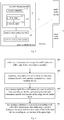
Fig. 4 is a flow chart of a method for controlling traffic lights according to an embodiment of the present disclosure; -
Fig. 5 is a flow chart of a method for controlling traffic lights according to another embodiment of the present disclosure; and -
Fig. 6 is a flow chart of a method for controlling traffic lights according to a further embodiment of the present disclosure. -
traffic light device 1,smart roadside device 2,autonomous vehicle 3,roadside sensing module 20,roadside processing module 30,roadside communication module 40,camera assembly 210,radar 220,first radar 221,second radar 222. - Reference will be made in detail to embodiments of the present disclosure. The same or similar elements and the elements having same or similar functions are denoted by same or like reference numerals throughout the descriptions. The embodiments described herein with reference to drawings are explanatory, illustrative, and configured to generally understand the present disclosure. The embodiments shall not be construed to limit the present disclosure.
- System and method for controlling traffic lights are described below with reference to the accompanying drawings.
-
Fig. 1 is a block diagram showing a structure of a system for controlling traffic lights according to an embodiment of the present disclosure. - As shown in
Fig. 1 , the system for controlling traffic lights includes atraffic light device 1 and asmart roadside device 2. Thesmart roadside device 2 includes aroadside sensing module 20 and aroadside processing module 30. - Specifically, the
roadside sensing module 20 includes acamera assembly 210 configured to collect information of an image for traffic lights of thetraffic light device 1, and aradar 220 configured to acquire first surrounding environment information of a road junction monitored by thesmart roadside device 2. - The
roadside processing module 30 is configured to determine traffic flow information of a red light lane according to the first surrounding environment information and the information of the image for the traffic lights, determine a duration of a green light according to the traffic flow information, and control a duration displaying the green light in a next cycle of thetraffic light device 1 according to the duration of the green light. - In an embodiment, the traffic flow information includes, but is not limited to, an amount of vehicles, a type and a length of a vehicle.
- It should be understood that the positional relationship between the
traffic light device 1 and thesmart roadside device 2 may be set differently. For example, in order to accurately acquire the traffic flow information of the road junction, thesmart roadside device 2 may be arranged near the road junction where thetraffic light device 1 is positioned. - Specifically, the
smart roadside device 2 is communicated with thetraffic light device 1, for example in a wireless manner. Thesmart roadside device 2 may determine the traffic flow information of the red light lane according to the environment information at the road junction, determine the duration of the green light according to the traffic flow information, and adjusting the duration displaying the green light in a next cycle of thetraffic light device 1 as the duration of the green light. Therefore, a duration in which a traffic light, for example a green light or a red light, is turned on or displayed, may be dynamically adjusted according to the traffic flow information at the road junction. - With the system for controlling traffic lights according to the embodiments of the present disclosure, the traffic flow information of the road junction may be acquired by the
smart roadside device 2 and durations of the traffic lights at the road junction may be flexibly adjusted according to the traffic flow information, thus improving traffic efficiency and reducing congestion at the road junction. - It should be noted that an
autonomous vehicle 3 has a relative small sensing range and is easily obstructed, and an in-vehicle camera may be influenced by a high beam from a vehicle driving towards theautonomous vehicle 3. In order to improve the quality for sensing the environment around theautonomous vehicle 3, besides the components shown inFig. 1 , the system is further included with theautonomous vehicle 3, and thesmart roadside device 2 further includes aroadside communication module 40 as shown inFig. 2 . - Specifically, the
autonomous vehicle 3 is configured to acquire second surrounding environment information around theautonomous vehicle 3. - In an embodiment, the
roadside processing module 30 is further configured to send the first surrounding environment information to theautonomous vehicle 3 via theroadside communication module 40. Theautonomous vehicle 3 is further configured to merge the first surrounding environment information with second surrounding environment information, and control a driving behavior according to merged surrounding environment information. - In this embodiment, the
autonomous vehicle 3 may receive the surrounding environment information sensed by thesmart roadside device 2, and merge the surrounding environment information which is sensed by itself with the received surrounding environment information to acquire final surrounding environment information, and make a strategy of an automatic driving behavior according to the final surrounding environment information. On this basis, a zone which cannot be detected by theautonomous vehicle 3 may be supplemented by the surrounding environment information collected by thesmart roadside device 2, thus improving driving safety of theautonomous vehicle 3. - In an embodiment, in order to further improve the driving safety of the
autonomous vehicle 3, theroadside processing module 30 is further configured to send at least one of time and duration displaying the green light to theautonomous vehicle 3. Theautonomous vehicle 3 may determine the driving behavior, which is in accordance with the traffic rules, based on at least one of the time and duration displaying the green light, and the surrounding environment information, thus improving the driving safety of theautonomous vehicle 3. - In order to accurately acquire the traffic flow information, in an embodiment of the present disclosure, the
autonomous vehicle 3 is further configured to send the second surrounding environment information to thesmart roadside device 2, and theroadside processing module 30 is further configured to merge the first surrounding environment information with the second surrounding environment information. - In this embodiment, the
smart roadside device 2 may merge the surrounding environment information of the road junction sensed by itself with the surrounding environment information sensed by theautonomous vehicle 3, to acquire more accurate environment information, thus further improving the accuracy of the traffic flow information determined by thesmart roadside device 2. - In an embodiment, as shown in
Fig. 3 , theradar 220 includes afirst radar 221 and asecond radar 222. The first andsecond radar - Specifically, the
first radar 221 is configured to detect surrounding environment information within a detection coverage of thefirst radar 221, and thesecond radar 222 is configured to detect surrounding environment information within a detection coverage of thesecond radar 222. - In an embodiment, a detection distance of the
first radar 221 is greater than a detection distance of thesecond radar 222. - The
roadside processing module 30 is further configured to determine information of obstacles near the target vehicle and obstacles far from the target vehicle according to the surrounding environment information detected by thefirst radar 221, the surrounding environment information detected by thesecond radar 222 and the image information collected by thecamera assembly 210. - In this embodiment, the
first radar 221 and thesecond radar 222 may accurately acquire the surrounding environment information for a relative long distant and for a relative short distance, respectively. On this basis, theroadside processing module 30 may determine the information of obstacles near and far from the target vehicle according to the surrounding environment information detected by thefirst radar 221 and thesecond radar 222. - It should be noted that, in order to further improve the capability for detecting obstacles, the type of the
first radar 221 and thesecond radar 222 may be determined to be the same or different from each other. - In an embodiment, the
first radar 221 and thesecond radar 222 are both laser radars. - For example, the
first radar 221 is a 64-line laser radar and thesecond radar 222 is a 16-line laser radar. - For another example, in order to accurately acquire the surrounding environment information, the
smart roadside device 2 may be provided with one 64-line laser radar and several (for example three or four) 16-line laser radars. - In another embodiment, the
first radar 221 is a laser radar and thesecond radar 222 is a millimeter wave radar. - In a further embodiment, the
first radar 221 is a laser radar and thesecond radar 222 is a microwave radar. - It should be noted that the
first radar 221, thesecond radar 222 and thecamera assembly 210 may be positioned differently. In an embodiment, thefirst radar 221 is located above thecamera assembly 210, and thesecond radar 222 is located below thecamera assembly 210. - In an embodiment, one or
more camera assemblies 210 may be provided. Moreover, in an embodiment, the image for the traffic lights captured by thecamera assembly 210 may include information of the road junction where the traffic lights are positioned. For example, there is a plurality ofcamera assemblies 210 corresponding to the road junction monitored by thesmart roadside device 2, and thesecamera assemblies 210 may be arranged at different positions and in different directions to collect the information of the image for the road junction including the traffic lights, thus further improving accuracy and reliability of a generated point cloud image. - In order to reduce the interference caused by components such as sensors and radars on the
camera assembly 210, in an embodiment, a shielding layer may cover at least part of thecamera assembly 210, so as to reduce the interference caused by theradar 220, thus increasing the imaging clarity of thecamera assembly 210 and improving the reliability of roadsidesmart device 2. - In an embodiment, the shielding layer does not cover camera lenses and heat dissipation components of the
camera assembly 210, in other words, the shielding layer covers components other than the lenses and the heat dissipation components of thecamera assembly 210, so as to reduce the interference caused by theradar 220, thus increasing the imaging clarity of thecamera assembly 210 and improving the reliability of roadsidesmart device 2. - In embodiments of the present disclosure, a method for controlling traffic lights is provided. Such a method may be performed by the system for controlling traffic lights described above, which is not described in details herein again.
-
Fig. 4 is a flow chart of a method for controlling traffic lights according to an embodiment of the present disclosure. - As shown in
Fig. 4 , the method for controlling traffic lights includes following steps. - In
block 401, information of an image for traffic lights of a traffic light device is collected via a camera assembly. - In
block 402, first surrounding environment information of the road junction monitored by a smart roadside device is acquired via a radar. - In
block 403, traffic flow information of a current red light lane is determined according to the first surrounding environment information and the information of the image for the traffic lights. - In
block 404, a duration of a green light is determined according to the traffic flow information, and a duration displaying the green light in a next cycle of the traffic light device is controlled according to the duration of the green light. - With the method for controlling traffic lights according to the embodiments of the present disclosure, the traffic flow information of the road junction may be acquired by the smart roadside device and durations of the traffic lights at the road junction may be flexibly adjusted according to the traffic flow information, thus improving traffic efficiency and reducing congestion at the road junction.
- It should be noted that an autonomous vehicle has a relative small sensing range and is easily obstructed, and an in-vehicle camera may be influenced by a high beam from a vehicle driving towards the autonomous vehicle. In order to improve the quality for sensing the environment around the autonomous vehicle, besides the steps shown in
Fig. 4 , the method includes a further step. - In
block 501, the first surrounding environment information is sent to an autonomous vehicle via a roadside communication module. - Accordingly, the autonomous vehicle receives the first surrounding environment information from the smart roadside device, merges the first surrounding environment information with second surrounding environment information sensed by the vehicle itself, and controls a driving behavior according to merged surrounding environment information.
- In order to acquire the traffic flow information more accurately, besides the steps shown in
Fig. 4 , the method further includes following steps as shown inFig. 6 . - In
block 601, second surrounding environment information sent by the autonomous vehicle is received. - In
block 602, the first surrounding environment information is merged with the second surrounding environment information. - In an embodiment of the present disclosure, a non-temporary computer-readable storage medium is provided, having stored therein computer programs that, when executed by a processor, cause the processor to perform a method for controlling traffic lights as described above.
- In an embodiment of the present disclosure, a computer program product is provided, having stored therein instructions that, when executed by a processor of a device, cause the device to perform a method for controlling traffic lights as described above.
- In the specification, unless specified or limited otherwise, relative terms such as "length", "width", "thickness", "inner", "outer", "lower", "upper", "horizontal", "vertical", "above", "below" as well as derivative thereof should be construed to refer to the orientation as then described or as shown in the drawings under discussion. These relative terms are for convenience of description and do not require that the present disclosure be constructed or operated in a particular orientation.
- In addition, terms such as "first" and "second" are used herein for purposes of description and are not intended to indicate or imply relative importance or significance. Thus, the feature defined with "first" and "second" may include one or more this feature. In the description of the present disclosure, unless specified otherwise, "a plurality of' means two or more than two, for example, two or three.
- In the specification, unless specified or limited otherwise, the terms "mounted", "connected", "coupled" and "fixed" and the like are used broadly, and may be, for example, fixed connections, detachable connections, or integral connections; may also be mechanical or electrical connections; may also be direct connections or indirect connections via intervening structures; may also be inner communications of two elements, which can be understood by those skilled in the art according to specific situations.
- In the specification, unless specified or limited otherwise, a structure in which a first feature is "on" or "below" a second feature may include an embodiment in which the first feature is in direct contact with the second feature, and may also include an embodiment in which the first feature and the second feature are not in direct contact with each other, but are contacted via an additional feature formed therebetween. Furthermore, a first feature "on," "above," or "on top of' a second feature may include an embodiment in which the first feature is right or obliquely "on," "above," or "on top of' the second feature, or just means that the first feature is at a height higher than that of the second feature; while a first feature "below," "under," or "on bottom of' a second feature may include an embodiment in which the first feature is right or obliquely "below," "under," or "on bottom of' the second feature, or just means that the first feature is at a height lower than that of the second feature.
- Reference throughout this specification to "an embodiment," "some embodiments," "an example," "a specific example," or "some examples," means that a particular feature, structure, material, or characteristic described in connection with the embodiment or example is included in at least one embodiment or example of the present disclosure. Thus, the appearances of the phrases such as "in some embodiments," "in one embodiment", "in an embodiment", "in another example," "in an example," "in a specific example," or "in some examples," in various places throughout this specification are not necessarily referring to the same embodiment or example of the present disclosure. Furthermore, the particular features, structures, materials, or characteristics may be combined in any suitable manner in one or more embodiments or examples. In addition, in the absence of contradiction, those skilled in the art can combine the different embodiments or examples described in this specification, or combine the features of different embodiments or examples.
- Any process or method described in a flow chart or described herein in other ways may be understood to include one or more modules, segments or portions of codes of executable instructions for achieving specific logical functions or steps in the process, and the scope of a preferred embodiment of the present disclosure includes other implementations, in which the order of execution is different from what is shown or discussed, including executing functions in a substantially simultaneous manner or in an opposite order according to the related functions. These and other aspects should be understood by those skilled in the art.
- The logic and/or step described in other manners herein or shown in the flow chart, for example, a particular sequence table of executable instructions for realizing the logical function, may be specifically achieved in any computer readable medium to be used by the instruction execution system, device or equipment (such as the system based on computers, the system including processors or other systems capable of obtaining the instruction from the instruction execution system, device and equipment and executing the instruction), or to be used in combination with the instruction execution system, device and equipment. As to the specification, "the computer readable medium" may be any device adaptive for including, storing, communicating, propagating or transferring programs to be used by or in combination with the instruction execution system, device or equipment. More specific examples of the computer readable medium include but are not limited to: an electronic connection (an electronic device) with one or more wires, a portable computer enclosure (a magnetic device), a random access memory (RAM), a read only memory (ROM), an erasable programmable read-only memory (EPROM or a flash memory), an optical fiber device and a portable compact disk read-only memory (CDROM). In addition, the computer readable medium may even be a paper or other appropriate medium capable of printing programs thereon, this is because, for example, the paper or other appropriate medium may be optically scanned and then edited, decrypted or processed with other appropriate methods when necessary to obtain the programs in an electric manner, and then the programs may be stored in the computer memories.
- It should be understood that each part of the present disclosure may be realized by the hardware, software, firmware or their combination. In the above embodiments, a plurality of steps or methods may be realized by the software or firmware stored in the memory and executed by the appropriate instruction execution system. For example, if it is realized by the hardware, likewise in another embodiment, the steps or methods may be realized by one or a combination of the following techniques known in the art: a discrete logic circuit having a logic gate circuit for realizing a logic function of a data signal, an application-specific integrated circuit having an appropriate combination logic gate circuit, a programmable gate array (PGA), a field programmable gate array (FPGA), etc
- It can be understood that all or part of the steps in the method of the above embodiments can be implemented by instructing related hardware via programs, the program may be stored in a computer readable storage medium, and the program includes one step or combinations of the steps of the method when the program is executed.
- In addition, each functional unit in the present disclosure may be integrated in one progressing module, or each functional unit exists as an independent unit, or two or more functional units may be integrated in one module. The integrated module can be embodied in hardware, or software. If the integrated module is embodied in software and sold or used as an independent product, it can be stored in the computer readable storage medium.
- The computer readable storage medium may be, but is not limited to, read-only memories, magnetic disks, or optical disks.
- Although explanatory embodiments have been shown and described, it would be appreciated by those skilled in the art that the above embodiments cannot be construed to limit the present disclosure.
Claims (15)
- A system for controlling traffic lights, comprising:a traffic light device (1), anda smart roadside device (2), comprising:a roadside sensing module (20) comprising:a camera assembly (210) configured to collect information of an image for traffic lights of the traffic light device (1), anda radar (220) configured to acquire first surrounding environment information of a road junction monitored by the smart roadside device (2), anda roadside processing module (30), configured to:determine traffic flow information of a red light lane according to the first surrounding environment information and the information of the image for the traffic lights,determine a duration of a green light according to the traffic flow information, andcontrol a duration displaying the green light in a next cycle of the traffic light device (1) according to the duration of the green light.
- The system according to claim 1, wherein the system further comprises an autonomous vehicle (3) configured to acquire second surrounding environment information around the autonomous vehicle (3).
- The system according to claim 2, wherein the smart roadside device (2) further comprises a roadside communication module (40), wherein
the roadside processing module (30) is further configured to send the first surrounding environment information to the autonomous vehicle (3) via the roadside communication module (40);
the autonomous vehicle (3) is configured to merge the first surrounding environment information with the second surrounding environment information, and control a driving behavior according to merged surrounding environment information. - The system according to claim 2 or 3, wherein the autonomous vehicle (3) is further configured to send the second surrounding environment information to the smart roadside device (2); and
the roadside processing module (30) is further configured to merge the first surrounding environment information with the second surrounding environment information. - The system according to any one of claims 1 to 4, wherein the radar (220) comprises:a first radar (221) configured to detect surrounding environment information within a detection coverage of the first radar (221), anda second radar (222) configured to detect surrounding environment information within a detection coverage of the second radar (222),wherein a detection distance of the first radar (221) is greater than a detection distance of the second radar (222).
- The system according to claim 5, wherein the first radar (221) and the second radar (222) are both laser radars.
- The system according to claim 5 or 6, wherein the first radar (221) is a 64-line laser radar and the second radar (222) is a 16-line laser radar.
- The system according to claim 5, wherein the first radar (221) is a laser radar and the second radar (222) is a millimeter wave radar.
- The system according to any one of claims 5 to 8, wherein the first radar (221) is located above the camera assembly (210), and the second radar (222) is located below the camera assembly (210).
- The system according to any one of claims 1 to 9, further comprising:
a shielding layer covering at least part of the camera assembly (210). - A method for controlling traffic lights, comprising:collecting (401) information of an image for traffic lights of a traffic light device via a camera assembly;acquiring (402), via a radar, first surrounding environment information of a road junction monitored by a smart roadside device;determining (403) traffic flow information of a current red light lane according to the first surrounding environment information and the information of the image for the traffic lights; anddetermining (404) a duration of a green light according to the traffic flow information, and controlling a duration displaying the green light in a next cycle of the traffic light device according to the duration of the green light.
- The method according to claim 11, further comprising:
sending (501) the first surrounding environment information to an autonomous vehicle via a roadside communication module. - The method according to claim 11 or 12, further comprising:receiving (601) second surrounding environment information sent by the autonomous vehicle,merging (602) the first surrounding environment information with the second surrounding environment information.
- A non-temporary computer-readable storage medium having stored therein computer programs that, when executed by a processor, cause the processor to perform a method for controlling traffic lights according to any one of claims 11 to 13.
- A program product having stored therein instructions that, when executed by a processor of a device, causes the device to perform a method for controlling traffic lights according to any one of claims 11 to 13.
Applications Claiming Priority (1)
| Application Number | Priority Date | Filing Date | Title |
|---|---|---|---|
| CN201811012996.2A CN110874938A (en) | 2018-08-31 | 2018-08-31 | Traffic light control system and traffic light control method |
Publications (1)
| Publication Number | Publication Date |
|---|---|
| EP3618033A1 true EP3618033A1 (en) | 2020-03-04 |
Family
ID=67658776
Family Applications (1)
| Application Number | Title | Priority Date | Filing Date |
|---|---|---|---|
| EP19191670.9A Withdrawn EP3618033A1 (en) | 2018-08-31 | 2019-08-14 | System and method for controlling traffic lights |
Country Status (4)
| Country | Link |
|---|---|
| US (1) | US11257367B2 (en) |
| EP (1) | EP3618033A1 (en) |
| JP (1) | JP7016336B2 (en) |
| CN (1) | CN110874938A (en) |
Cited By (1)
| Publication number | Priority date | Publication date | Assignee | Title |
|---|---|---|---|---|
| EP3859708A1 (en) * | 2020-09-23 | 2021-08-04 | Beijing Baidu Netcom Science And Technology Co. Ltd. | Traffic light image processing method and device, and roadside device |
Families Citing this family (11)
| Publication number | Priority date | Publication date | Assignee | Title |
|---|---|---|---|---|
| JP7222343B2 (en) * | 2019-11-28 | 2023-02-15 | トヨタ自動車株式会社 | Driving support device |
| CN113496602B (en) * | 2020-04-03 | 2023-01-31 | 上海丰豹商务咨询有限公司 | Intelligent roadside tool box |
| DE102020123831A1 (en) * | 2020-09-14 | 2022-03-17 | ASFINAG Maut Service GmbH | Concept for supporting an at least partially automated motor vehicle |
| CN111931726B (en) * | 2020-09-23 | 2024-06-11 | 阿波罗智联(北京)科技有限公司 | Traffic light detection method, device, computer storage medium and road side equipment |
| CN112216110A (en) * | 2020-10-16 | 2021-01-12 | 王晔 | Intelligent traffic monitoring system and method with traffic flow detection function |
| KR20220083945A (en) * | 2020-12-11 | 2022-06-21 | 현대자동차주식회사 | Apparatus for providing traffic light, system having the same and method thereof |
| TWI856273B (en) * | 2021-10-14 | 2024-09-21 | 陳崗熒 | Method for automatic decision of traffic control |
| CN116153055A (en) * | 2021-11-22 | 2023-05-23 | 大唐移动通信设备有限公司 | A traffic information transmission system, roadside unit and data processing method |
| CN115359653B (en) * | 2022-07-25 | 2024-11-01 | 清华大学 | Traffic signal control method and device |
| CN115294780A (en) * | 2022-08-23 | 2022-11-04 | 深圳市公安局交通警察支队龙岗大队 | Intelligent variable lane traffic flow control system and control method thereof |
| CN118393491B (en) * | 2024-06-25 | 2024-11-01 | 杭州海康威视数字技术股份有限公司 | Laser vision integrated machine |
Citations (5)
| Publication number | Priority date | Publication date | Assignee | Title |
|---|---|---|---|---|
| GB2535320A (en) * | 2015-01-29 | 2016-08-17 | Agd Systems Ltd | Portable traffic light control system and portable traffic light signal |
| US20170330456A1 (en) * | 2016-05-16 | 2017-11-16 | Ford Global Technologies, Llc | Traffic lights control for fuel efficiency |
| US20180091438A1 (en) * | 2016-09-26 | 2018-03-29 | Kyland Technology Co., Ltd. | Method and equipment for processing information in intelligent traffic cloud control system |
| US20180122231A1 (en) * | 2016-10-31 | 2018-05-03 | Echelon Corporation | Video data and gis mapping for traffic monitoring, event detection and change predicition |
| US20180158324A1 (en) * | 2016-12-06 | 2018-06-07 | Acyclica Inc. | Localized traffic data collection |
Family Cites Families (32)
| Publication number | Priority date | Publication date | Assignee | Title |
|---|---|---|---|---|
| JP2001236593A (en) | 2000-02-24 | 2001-08-31 | Hitachi Ltd | Traffic signal control device |
| JP3680815B2 (en) | 2002-05-13 | 2005-08-10 | 住友電気工業株式会社 | Traffic signal control method |
| JP4541072B2 (en) | 2004-08-30 | 2010-09-08 | 小糸工業株式会社 | Traffic signal control apparatus and traffic signal system using the same |
| JP4738031B2 (en) | 2005-03-18 | 2011-08-03 | 小糸工業株式会社 | Traffic signal control apparatus and traffic signal system using the same |
| US8610596B2 (en) * | 2010-02-11 | 2013-12-17 | Global Traffic Technologies, Llc | Monitoring and diagnostics of traffic signal preemption controllers |
| JP2012181651A (en) * | 2011-03-01 | 2012-09-20 | Sumitomo Electric Ind Ltd | Traffic signal control system, device, and method |
| JP2012221091A (en) | 2011-04-06 | 2012-11-12 | Mitsubishi Electric Corp | Traffic signal control device and traffic signal control system using the same |
| CN102333184A (en) * | 2011-07-20 | 2012-01-25 | 苏州盛开信息科技有限公司 | Web camera |
| CN103379257A (en) * | 2012-04-14 | 2013-10-30 | 徐秋平 | Network camera |
| CN202652362U (en) * | 2012-06-04 | 2013-01-02 | 北京嘉恒中自图像技术有限公司 | Gigabit network camera used for X-ray equipment |
| US11004337B2 (en) * | 2012-12-28 | 2021-05-11 | Balu Subramanya | Advanced parking management system |
| US20140210646A1 (en) * | 2012-12-28 | 2014-07-31 | Balu Subramanya | Advanced parking and intersection management system |
| CN104243772A (en) * | 2013-06-06 | 2014-12-24 | 鸿富锦精密工业(深圳)有限公司 | Camera |
| US20150213165A1 (en) * | 2014-01-27 | 2015-07-30 | Livermore Software Technology Corporation | Methods And Systems For Conducting Design Sensitivity Analysis |
| JP6394446B2 (en) | 2015-03-13 | 2018-09-26 | オムロン株式会社 | Display control instruction unit, signal display control system, display control instruction method, and display control instruction program |
| WO2016147350A1 (en) | 2015-03-18 | 2016-09-22 | 住友電気工業株式会社 | Signal control device, computer program, storage medium, and signal control method |
| US10507807B2 (en) * | 2015-04-28 | 2019-12-17 | Mobileye Vision Technologies Ltd. | Systems and methods for causing a vehicle response based on traffic light detection |
| JP6398877B2 (en) | 2015-06-01 | 2018-10-03 | 株式会社デンソー | Automatic operation control device |
| CN204904585U (en) * | 2015-08-03 | 2015-12-23 | 兰州市公安局交通警察支队交通科研所 | High definition video all -in -one, traffic signal system and because traffic signals control system of vision sensing |
| CN106384517A (en) * | 2015-08-03 | 2017-02-08 | 兰州市公安局交通警察支队交通科研所 | Traffic signal control method based on visual sensing, apparatus and system thereof |
| DE102015220821A1 (en) | 2015-10-26 | 2017-04-27 | Robert Bosch Gmbh | Controlling a motor vehicle |
| JP6711016B2 (en) | 2016-02-26 | 2020-06-17 | 株式会社デンソー | Driving support device |
| US11255663B2 (en) * | 2016-03-04 | 2022-02-22 | May Patents Ltd. | Method and apparatus for cooperative usage of multiple distance meters |
| JP6508132B2 (en) | 2016-06-09 | 2019-05-08 | 株式会社デンソー | Traffic control device and traffic control method |
| CN205943100U (en) * | 2016-07-28 | 2017-02-08 | 清华大学苏州汽车研究院(吴江) | HMI shows system for V2X scene |
| CN106199603B (en) * | 2016-08-04 | 2018-12-07 | 深圳卓影科技有限公司 | A kind of vehicle anti-collision prior-warning device and its calibration method |
| JP6684681B2 (en) | 2016-08-10 | 2020-04-22 | パナソニック インテレクチュアル プロパティ コーポレーション オブ アメリカPanasonic Intellectual Property Corporation of America | Dynamic map construction method, dynamic map construction system and mobile terminal |
| CN107230369A (en) * | 2016-12-15 | 2017-10-03 | 山东科技大学 | A kind of vehicle guidance method based on RFID roadmarkings |
| CN107063275B (en) * | 2017-03-24 | 2020-05-12 | 重庆邮电大学 | Intelligent vehicle map fusion system and method based on road side equipment |
| CN106846840B (en) * | 2017-04-20 | 2019-09-13 | 成都信息工程大学 | A Traffic Light Control Method Based on Road Flow |
| CN107807633A (en) * | 2017-09-27 | 2018-03-16 | 北京图森未来科技有限公司 | A roadside device, vehicle-mounted device, and automatic driving perception method and system |
| CN107945540A (en) * | 2017-10-27 | 2018-04-20 | 清华大学苏州汽车研究院(吴江) | A kind of bus or train route cooperative control system of signal lamp intersection |
-
2018
- 2018-08-31 CN CN201811012996.2A patent/CN110874938A/en active Pending
-
2019
- 2019-08-12 US US16/538,610 patent/US11257367B2/en active Active
- 2019-08-14 EP EP19191670.9A patent/EP3618033A1/en not_active Withdrawn
- 2019-08-29 JP JP2019156513A patent/JP7016336B2/en not_active Expired - Fee Related
Patent Citations (5)
| Publication number | Priority date | Publication date | Assignee | Title |
|---|---|---|---|---|
| GB2535320A (en) * | 2015-01-29 | 2016-08-17 | Agd Systems Ltd | Portable traffic light control system and portable traffic light signal |
| US20170330456A1 (en) * | 2016-05-16 | 2017-11-16 | Ford Global Technologies, Llc | Traffic lights control for fuel efficiency |
| US20180091438A1 (en) * | 2016-09-26 | 2018-03-29 | Kyland Technology Co., Ltd. | Method and equipment for processing information in intelligent traffic cloud control system |
| US20180122231A1 (en) * | 2016-10-31 | 2018-05-03 | Echelon Corporation | Video data and gis mapping for traffic monitoring, event detection and change predicition |
| US20180158324A1 (en) * | 2016-12-06 | 2018-06-07 | Acyclica Inc. | Localized traffic data collection |
Cited By (2)
| Publication number | Priority date | Publication date | Assignee | Title |
|---|---|---|---|---|
| EP3859708A1 (en) * | 2020-09-23 | 2021-08-04 | Beijing Baidu Netcom Science And Technology Co. Ltd. | Traffic light image processing method and device, and roadside device |
| US11790772B2 (en) | 2020-09-23 | 2023-10-17 | Apollo Intelligent Connectivity (Beijing) Technology Co., Ltd | Traffic light image processing |
Also Published As
| Publication number | Publication date |
|---|---|
| CN110874938A (en) | 2020-03-10 |
| US11257367B2 (en) | 2022-02-22 |
| US20200074856A1 (en) | 2020-03-05 |
| JP2020038647A (en) | 2020-03-12 |
| JP7016336B2 (en) | 2022-02-04 |
Similar Documents
| Publication | Publication Date | Title |
|---|---|---|
| US11257367B2 (en) | System and method for controlling traffic lights | |
| EP3618026A1 (en) | Roadside sensing system based on vehicle infrastructure cooperation, and method for controlling vehicle thereof | |
| US11579285B2 (en) | Intelligent roadside unit | |
| US11099272B2 (en) | Intelligent roadside unit | |
| CN110782465B (en) | Ground segmentation method and device based on laser radar and storage medium | |
| US11217091B2 (en) | Smart roadside unit and method for processing information by smart roadside unit | |
| EP3618035B1 (en) | Intelligent roadside unit, control method and storage medium | |
| JP2020038651A (en) | Intelligent roadside unit and control method thereof, computer device and storage medium | |
| EP4184278A1 (en) | Automatic recharging method and apparatus, storage medium, charging base, and system | |
| EP3618424B1 (en) | Smart roadside unit and method for processing information by smart roadside unit | |
| CN113370993A (en) | Control method and control system for automatic driving of vehicle | |
| EP4071578B1 (en) | Light source control method for vision machine, and vision machine | |
| CN112180353A (en) | Target object confirmation method and system and storage medium | |
| US11210938B2 (en) | Intelligent road side unit and regulation method thereof | |
| CN110308460B (en) | Parameter determination method and system of sensor | |
| JP7537411B2 (en) | Information processing system, information processing method, and program | |
| US12459541B2 (en) | Method of detecting moving objects, device, electronic device, and storage medium | |
| CN115932858A (en) | Millimeter wave angle radar system for vehicle |
Legal Events
| Date | Code | Title | Description |
|---|---|---|---|
| PUAI | Public reference made under article 153(3) epc to a published international application that has entered the european phase |
Free format text: ORIGINAL CODE: 0009012 |
|
| STAA | Information on the status of an ep patent application or granted ep patent |
Free format text: STATUS: THE APPLICATION HAS BEEN PUBLISHED |
|
| STAA | Information on the status of an ep patent application or granted ep patent |
Free format text: STATUS: REQUEST FOR EXAMINATION WAS MADE |
|
| AK | Designated contracting states |
Kind code of ref document: A1 Designated state(s): AL AT BE BG CH CY CZ DE DK EE ES FI FR GB GR HR HU IE IS IT LI LT LU LV MC MK MT NL NO PL PT RO RS SE SI SK SM TR |
|
| AX | Request for extension of the european patent |
Extension state: BA ME |
|
| 17P | Request for examination filed |
Effective date: 20200217 |
|
| RBV | Designated contracting states (corrected) |
Designated state(s): AL AT BE BG CH CY CZ DE DK EE ES FI FR GB GR HR HU IE IS IT LI LT LU LV MC MK MT NL NO PL PT RO RS SE SI SK SM TR |
|
| RAP1 | Party data changed (applicant data changed or rights of an application transferred) |
Owner name: APOLLO INTELLIGENT DRIVING TECHNOLOGY (BEIJING) CO., LTD. |
|
| STAA | Information on the status of an ep patent application or granted ep patent |
Free format text: STATUS: EXAMINATION IS IN PROGRESS |
|
| 17Q | First examination report despatched |
Effective date: 20220620 |
|
| GRAP | Despatch of communication of intention to grant a patent |
Free format text: ORIGINAL CODE: EPIDOSNIGR1 |
|
| STAA | Information on the status of an ep patent application or granted ep patent |
Free format text: STATUS: GRANT OF PATENT IS INTENDED |
|
| INTG | Intention to grant announced |
Effective date: 20240318 |
|
| STAA | Information on the status of an ep patent application or granted ep patent |
Free format text: STATUS: THE APPLICATION IS DEEMED TO BE WITHDRAWN |
|
| 18D | Application deemed to be withdrawn |
Effective date: 20240719 |