EP3617834A1 - Method for operating handheld device, handheld device and computer-readable recording medium thereof - Google Patents
Method for operating handheld device, handheld device and computer-readable recording medium thereof Download PDFInfo
- Publication number
- EP3617834A1 EP3617834A1 EP19162056.6A EP19162056A EP3617834A1 EP 3617834 A1 EP3617834 A1 EP 3617834A1 EP 19162056 A EP19162056 A EP 19162056A EP 3617834 A1 EP3617834 A1 EP 3617834A1
- Authority
- EP
- European Patent Office
- Prior art keywords
- handheld device
- hand state
- touch
- sensor
- processor
- Prior art date
- Legal status (The legal status is an assumption and is not a legal conclusion. Google has not performed a legal analysis and makes no representation as to the accuracy of the status listed.)
- Granted
Links
Images






Classifications
-
- G—PHYSICS
- G06—COMPUTING OR CALCULATING; COUNTING
- G06F—ELECTRIC DIGITAL DATA PROCESSING
- G06F1/00—Details not covered by groups G06F3/00 - G06F13/00 and G06F21/00
- G06F1/16—Constructional details or arrangements
- G06F1/1613—Constructional details or arrangements for portable computers
- G06F1/1626—Constructional details or arrangements for portable computers with a single-body enclosure integrating a flat display, e.g. Personal Digital Assistants [PDAs]
-
- G—PHYSICS
- G06—COMPUTING OR CALCULATING; COUNTING
- G06F—ELECTRIC DIGITAL DATA PROCESSING
- G06F3/00—Input arrangements for transferring data to be processed into a form capable of being handled by the computer; Output arrangements for transferring data from processing unit to output unit, e.g. interface arrangements
- G06F3/01—Input arrangements or combined input and output arrangements for interaction between user and computer
- G06F3/03—Arrangements for converting the position or the displacement of a member into a coded form
- G06F3/041—Digitisers, e.g. for touch screens or touch pads, characterised by the transducing means
- G06F3/0416—Control or interface arrangements specially adapted for digitisers
-
- G—PHYSICS
- G06—COMPUTING OR CALCULATING; COUNTING
- G06F—ELECTRIC DIGITAL DATA PROCESSING
- G06F1/00—Details not covered by groups G06F3/00 - G06F13/00 and G06F21/00
- G06F1/16—Constructional details or arrangements
- G06F1/1613—Constructional details or arrangements for portable computers
- G06F1/1633—Constructional details or arrangements of portable computers not specific to the type of enclosures covered by groups G06F1/1615 - G06F1/1626
- G06F1/1684—Constructional details or arrangements related to integrated I/O peripherals not covered by groups G06F1/1635 - G06F1/1675
-
- G—PHYSICS
- G06—COMPUTING OR CALCULATING; COUNTING
- G06F—ELECTRIC DIGITAL DATA PROCESSING
- G06F3/00—Input arrangements for transferring data to be processed into a form capable of being handled by the computer; Output arrangements for transferring data from processing unit to output unit, e.g. interface arrangements
- G06F3/01—Input arrangements or combined input and output arrangements for interaction between user and computer
- G06F3/048—Interaction techniques based on graphical user interfaces [GUI]
- G06F3/0487—Interaction techniques based on graphical user interfaces [GUI] using specific features provided by the input device, e.g. functions controlled by the rotation of a mouse with dual sensing arrangements, or of the nature of the input device, e.g. tap gestures based on pressure sensed by a digitiser
- G06F3/0488—Interaction techniques based on graphical user interfaces [GUI] using specific features provided by the input device, e.g. functions controlled by the rotation of a mouse with dual sensing arrangements, or of the nature of the input device, e.g. tap gestures based on pressure sensed by a digitiser using a touch-screen or digitiser, e.g. input of commands through traced gestures
-
- G—PHYSICS
- G06—COMPUTING OR CALCULATING; COUNTING
- G06F—ELECTRIC DIGITAL DATA PROCESSING
- G06F2203/00—Indexing scheme relating to G06F3/00 - G06F3/048
- G06F2203/041—Indexing scheme relating to G06F3/041 - G06F3/045
- G06F2203/04104—Multi-touch detection in digitiser, i.e. details about the simultaneous detection of a plurality of touching locations, e.g. multiple fingers or pen and finger
-
- G—PHYSICS
- G06—COMPUTING OR CALCULATING; COUNTING
- G06F—ELECTRIC DIGITAL DATA PROCESSING
- G06F3/00—Input arrangements for transferring data to be processed into a form capable of being handled by the computer; Output arrangements for transferring data from processing unit to output unit, e.g. interface arrangements
- G06F3/01—Input arrangements or combined input and output arrangements for interaction between user and computer
- G06F3/03—Arrangements for converting the position or the displacement of a member into a coded form
- G06F3/041—Digitisers, e.g. for touch screens or touch pads, characterised by the transducing means
- G06F3/0412—Digitisers structurally integrated in a display
-
- G—PHYSICS
- G06—COMPUTING OR CALCULATING; COUNTING
- G06F—ELECTRIC DIGITAL DATA PROCESSING
- G06F3/00—Input arrangements for transferring data to be processed into a form capable of being handled by the computer; Output arrangements for transferring data from processing unit to output unit, e.g. interface arrangements
- G06F3/01—Input arrangements or combined input and output arrangements for interaction between user and computer
- G06F3/048—Interaction techniques based on graphical user interfaces [GUI]
- G06F3/0481—Interaction techniques based on graphical user interfaces [GUI] based on specific properties of the displayed interaction object or a metaphor-based environment, e.g. interaction with desktop elements like windows or icons, or assisted by a cursor's changing behaviour or appearance
Definitions
- the present disclosure relates to a method for operating a handheld device, a handheld device, and a computer-readable recording medium thereof, and more particularly, relates to a handheld device being operated through sensors disposed on the sides of the handheld device.
- Handheld device such as mobile phone, tablet PC and the like are popular and being used in all kind of occasions. People may use the handheld device for playing multimedia, web browsing, navigation, gaming, and etc.
- the display technology has been developed with a significant breakthrough, lots of manufactories trend to design handheld devices with slim bezel, so as to increase screen-to-body ratios of the handheld devices and provide better visual experience to users.
- many users like handheld devices with large screen but they generally operate the handheld device with one hand, so that a part of the screen may not be touched with one hand because of hand size.
- software developers usually do not design user interfaces (UIs) of the handheld devices for a special purpose of one hand use, so that the user have to operate with two hands in some situation. Accordingly, one hand experience for handheld devices should be improved.
- UIs user interfaces
- the present disclosure is directed to a method for operating a handheld device, a handheld device, and a computer-readable recording medium thereof, which determine the handheld device is held by left hand or right hand, so as to provide a corresponding UI for a specific hand.
- the handheld device at least includes, but not limited to, a body, a first sensor, a second sensor, and a processor.
- the first sensor is disposed on a first side of the body.
- the second sensor is disposed on a second side of the body different from the first side.
- the processor is coupled to the first and second sensors and configured to obtain sensing data of the first and second sensors, and to determine the handheld device is in a left hand state or a right hand state according to a compared result between sensing data of the first and second sensors, where the compared result includes a force comparison between forces applied on the first and second sides of the body, the first side of the body corresponds to the right hand state, and the second side of the body corresponds to the left hand state.
- the compared result comprises a number comparison between numbers of touch point detected by the first and second sensors and a distance comparison between distances between two touch points on the first and second sides of the body
- the processor is configured to, in response to the number comparison being the same, determine the handheld device is in the left hand state or the right hand state according to the distance comparison in response to the number of touch point detected by one of the first and second sensors being two, and to determine the handheld device is in the left hand state or the right hand state according to the force comparison in response to the number of touch point detected by one of the first and second sensors being one.
- the processor is configured to determine whether a force difference of the force comparison is larger than a force difference threshold to confirm the handheld device is in the left hand state or the right hand state.
- the processor is configured to determine whether a touch area or a touch length detected on one of the first and second sides of the body is larger than a first threshold in response to the force difference being not larger than the force difference threshold, to confirm the handheld device is in the left hand state or the right hand state.
- the handheld device further comprises a third sensor coupled to the processor.
- the processor is configured to determine an orientation of the body according to sensing data of the third sensor, and to determine the handheld device is in the left hand state or the right hand state according to the orientation of the body.
- the compared result comprises a number comparison between numbers of touch point detected by the first and second sensors
- the processor is configured to, in response the number comparison being different, determine the handheld device is in the left hand state or the right hand state according to a touch area or a touch length detected on the first side of the body and the force comparison in response to the number of touch point detected by the second sensor being larger than the number of touch point detected by the first sensor, and to determine the handheld device is in the left hand state or the right hand state according to a touch area or a touch length detected on the second side of the body and the force comparison in response to the number of touch point detected by the first sensor being larger than the number of touch point detected by the second sensor.
- the compared result comprises a number comparison between numbers of touch point detected by the first and second sensors.
- the processor is configured to determine the handheld device is in the left hand state or the right hand state according to a distance between two touch points on one of the first and second sides of the body in response the number comparison being different.
- the processor is configured to determine the operational hand state is not in a hold state in response to numbers of touch points detected on the first and second sides of the body being both larger than two.
- the processor is configured to determine the handheld device is not in a hold state in response to a number of touch point detected on one of the first and second sides of the body being zero or a total touch area or a total touch length detected on one of the first and second sides of the body being less than a second threshold.
- the hold state includes the left hand state and the right hand state.
- the processor is configured to determine the handheld device is in a hold state in response to a total touch area or a total touch length detected on one of the first and second sides of the body being larger than a third threshold and at least one touch point being detected on both of the first and second sides of the body, wherein the third threshold is larger than the second threshold.
- the handheld device further comprises a display coupled to the processor.
- the processor is configured to display an operating interface corresponding to the first side of the body on the display in response to the handheld device being in the right hand state, and display the operating interface corresponding to the second side of the body on the display in response to the handheld device being in the left hand state.
- the method for operating a handheld device includes, but not limited to, a body, a first sensor disposed on a first side of the body and a second sensor disposed on a second side of the body different from the first side.
- the method includes the following steps. Sensing data of the first and second sensors is obtained.
- the handheld device being in a left hand state or a right hand state is determined according to a compared result between sensing data of the first and second sensors, where the compared result includes a force comparison between forces applied on the first and second sides of the body, the first side of the body corresponds to the right hand state, and the second side of the body corresponds to the left hand state.
- the non-transitory computer readable recording medium records computer program to be loaded by a processor of a handheld device having two sensors disposed on two sides thereof to execute the aforementioned method.
- FIG. 1 is a block diagram illustrating a handheld device 100 according to one of the exemplary embodiments of the disclosure.
- the handheld device 100 at least includes, but not limited to, a first sensor 110, a second sensor 120, a display 130 and a processor 150.
- the handheld device 100 could be mobile phone, tablet PC, camera, handheld game console, multimedia player, etc.
- the first sensor 110 is disposed on a first side S1 of body 140 of the handheld device 100
- the second sensor 120 is disposed on a second side S2 of the body 140, where the second side S2 is opposite to the first side S1.
- the first side S1 of the body 140 is the right side of the body 140
- the second side S2 is the left side of the body 140.
- the first sensor 110 and the second sensor 120 could be capacitive sensor, resistive sensor, piezoelectric sensor, electromagnetic sensor, other type of pressure sensors, or a combination of aforesaid sensors, to detect the presence of objects (e.g. finger, or clamp) being placed on the first side S1 and the second side S2, and generate sensing data including touch position, force or pressure related raw data.
- first and second sensor 110, 120 may cover a portion or entire of the first and second sides S1, S2, and each sensor 110, 120 may include a piece of sensing element or multiple sensing elements arranged on the corresponding side S1, S2 of the body 140 with single type sensor or various type of pressure sensors. If the sensing elements are arranged in one-dimension, for example, the arranged sensing elements form an line extended from the top to the button of side S1 or/and S2, the sensing data of the sensing elements can be used for detecting a touch length of object (e.g. finger, clamp, or other object).
- a touch length of object e.g. finger, clamp, or other object.
- the sending elements are arranged in two-dimension, for example, the arranged sensing elements form an rectangle shape having four sides near to edges of side S1 or/and S2, the sensing data of the sensing elements can be used for detecting a touch area of object (e.g. finger, clamp, or other object).
- object e.g. finger, clamp, or other object.
- the shapes formed by the arranged sensing elements on sides S1 and S2 can be modified according to actual requirement, and the exemplary embodiment of the disclosure is not limited thereto.
- the display 130 could be a liquid crystal display (LCD), light emitting diode (LED), organic light emitting diode (OLED), or other type of display.
- LCD liquid crystal display
- LED light emitting diode
- OLED organic light emitting diode
- Two sides of the display 130 locates near the first and second sides S1, S2 of the body 140 as shown in FIGs 2A and 2B .
- the display 130 may be integrated with touch panel (including touch sensor such as resistive touch sensor, capacitive touch sensor, optic touch sensor or the likes), so as to provide display and touch sensing functions.
- the processor 150 is coupled to the first sensor 110, the second sensor 120 and display 140.
- the processor 150 may be implemented by using a programmable unit, such as a central processing unit (CPU), a micro-processor, a micro-controller, a digital signal processing (DSP) chip, a field programmable gate array (FPGA), and so on.
- the function of the processor 150 may also be implemented by an independent electronic device or an integrated circuit (IC), and the operation of the processor 150 may also be implemented by software.
- the processor 150 is programmed to execute the functions or steps that would be described below.
- FIG. 3 is a flowchart of a method for operating the handheld device 100 according to one of exemplary embodiments of the disclosure.
- the method of this embodiment is adapted for the handheld device 100 of FIGs. 1 , 2A and 2B .
- the method of this embodiment of the disclosure is described first with reference to the components of the handheld device 100. Nevertheless, the processes of this method may be adjusted according to the actual needs and thus are not limited to the following.
- the processor 150 obtains sensing data of the first and second sensors 110, 120 (Step S310).
- the processor 150 may analyze the raw data (such as strength value and corresponding position) included in the sensing data, to determine the number, position, force and pressure of objects (e.g. finger or clamp) detected or applied on two sides S1, S2 of the body 140.
- objects e.g. finger or clamp
- the processor 150 determines the handheld device 100 is in a left hand state or a right hand state according to a compared result between sensing data of the first and second sensors 110, 120 (Step S330). Specifically, in general, when user holds the body 140 of the handheld device 100 by his/her right hand, the thumb and/or palm of the right hand abuts against the first side S1 of the body 140, and at least one of the other fingers of the right hand abuts against the second side S2 of the body 140.
- the processor 140 determines an operational hand state is the right hand state (i.e., the handheld device 100 is in the right hand state). If another situation that the body 140 is held by the left hand is detected, the processor 140 determines the operational hand state is the left hand state (i.e., the handheld device 100 is in the left hand state).
- the user usually uses the thumb to operate the handheld device 100 (or touch the display 140) no matter which hand he/she uses.
- the first side S1 of the body 140 is defined as corresponding to the right hand state because the thumb of right hand abuts against the first side S1.
- the second side S2 of the body 140 is defined as corresponding to the left hand state because the thumb of the left hand abuts against the second side S2.
- the compared result may include one or any combination of number comparison, force comparison, distance comparison and touch lengths/areas of touch point on two sides S1 and S2, which would be discussed in detail later.
- FIG. 4 is a flowchart illustrating a procedure of the handheld device 100 for determining the operational hand state according to one of the exemplary embodiments of the disclosure. It is assumed that processor 150 detects the operational hand state is a hold state (i.e., the body 140 is held by hand), and the determination of the hold state would be described below in detail.
- a hold state i.e., the body 140 is held by hand
- the numbers of touch point, distances between two touch points, touched areas (or touch length) and applied forces on the two side S1, S2 of the body 140, which are detected by the first and second sensors 110, 120 may be the same or different, these number comparison, distance comparison, area comparison and force comparison between two sides S1, S2 would help to determine operational hand state of the handheld device 100.
- the processor 150 determines whether the number of touch point detected by one of the first and second sensors 110, 120 is zero or the numbers of touch point detected by the two sensors 110, 120 are both larger than two (S410)? It is assumed that, when the handheld device 100 is held by one hand, one of the first and second sensors 110, 120 may detect at most two touch points on one side of the body 140 against which a thumb and/or a palm abuts, where the two touch points may be generated by the thumb and/or a part of palm.
- the processor 150 determines the operational hand state is a un-hold state (i.e., the handheld device 100 is not in a hold state, where the hold state includes the left hand state and the right hand state) (Step S415).
- the body 140 is held by a mobile holder, so that more than two touch points are detected on two side S1, S2.
- the body 140 is merely rested or abutted against hand, but is not held by hand, so that at least one of the sensors 110, 120 does not detect any touch point.
- the processor 150 determines the operational hand state is still the hold state. In other words, if the numbers of touch points detected on both sides S1, S2 both are between 1 and 2, or if the number of touch point detected on one side S1/S2 is larger than two and the number of touch point detected on the other side S2/S1 is less than three, the operational hand state is still in the hold state.
- the processor 150 determines whether the number of touch point detected by one of the first and second sensors 110, 120 is larger than two (Step S420)? It is assumed that, when the handheld device 100 is held by one hand, one of the first and second sensors 110, 120 may detect more two touch points on one side of the body 140 opposite to the other side of body 140 against which a thumb abuts, where the touch points may be generated by index finger, middle finger, ring finger or little finger. If more than two fingers are detected on the first side S1 of the body 140, the processor 150 determines the handheld device 100 is in the left hand state; if more than two fingers are detected on the second side S2 of the body 140, the processor 150 determines the handheld device 100 is in the right hand state (Step S425).
- the processor 140 determines whether the numbers of touch point detected by the first and second sensors 110, 120 are the same or whether the number comparison between the numbers of touch point detected on the first and second sides S1, S2 of the body 140 is zero (Step S430)? Different compared results would lead the step into different determination procedures. If the number comparison of the compared result is that the number difference is zero or the numbers are the same (e.g.
- the processor 150 would determines the operational hand state is the left or right hand state according to the number of touch point, pressure (or force) on two sensors 110, 120 and the distance between touch points detected on each sensor 110, 120 (Step S435, it is called a first determination procedure).
- the processor 150 would determine whether the number of touch point detected by both first and second sensors 110, 120 is one or two (Step S510). If the number of touch point detected by both first and second sensors 110, 120 is two, the processor 150 would determine the handheld device 100 is in the left hand state or the right hand state according to the distance comparison (e.g. the difference between distance between two touch points on the first side S1 and distance between two touch points on the second side S2) (Step S520).
- the distance comparison e.g. the difference between distance between two touch points on the first side S1 and distance between two touch points on the second side S2
- a first distance between one position against which the thumb abuts and another position against which the palm abuts may be larger than a second distance between any two positions against which the other two neighboring fingers abut.
- the processor 150 determines the handheld device 100 is in the left hand state (Step S530); if the distance comparison is that the distance between two touch points on the second side S1 is larger than the distance between two touch points on the first side S2 or the subtraction of the distance D2 from the distance D1 is larger than the threshold T D , the processor 150 determines the handheld device 100 is in the right hand state (Step S540).
- the processor 150 may further determine whether the force difference of the force comparison between two forces F1, F2 applied on two sides S1 and S2 is larger than a force difference threshold T F to determine the handheld device 100 is in the left hand state or the right hand state (Step S521). If the force difference is larger than the force difference threshold T F (i.e. F1-F2>T F ) or the force F1 applied on the first side S1 is larger than the force F2 applied on the second side S2 (i.e. F1>F2), the processor 150 would determine that the handheld device 100 is in the left hand state (Step S523).
- the processor 150 would determine that the handheld device 100 is in the right hand state (Step S527).
- the processor 150 can determine one force on each side S1/S2 for the force comparison. For example, the processor 150 may use the maximum force detected on side S1 to compare with the maximum force detected on the side S2. Alternatively, the processor 150 may use the average force detected on side S1 to compare with the average force detected on the side S2.
- the processor 150 use other rules to determine the hold state (Step S525). There are multiple rules, in one exemplary embodiment, if the force difference is less than the force difference threshold T F , the processor 150 can further determine whether a touch area or a touch length detected on one of the first and second sides S1, S2 of the body 140 is larger than a first threshold (e.g. 350 or 400 square millimetre, 60 or 63 millimetres) to confirm the handheld device 100 is in the left hand state or the right hand state. In general, the touch area of the thumb and/or the palm is larger than the other fingers.
- a first threshold e.g. 350 or 400 square millimetre, 60 or 63 millimetres
- the processor 150 determines the handheld device 100 is in the right hand state; if the touch area or the touch length detected on the second side S2 of the body is larger than the first threshold, the processor 150 determines the handheld device 100 is in the left hand state.
- the handheld device 100 may further include a third sensor (not shown) coupled to the processor 150.
- the third sensor could be a g-sensor, a magnetic sensor, an accelerator, or other sensors that provide sensing data regarding to the orientation of the handheld device 100, so that the processor 150 may determine the orientation of the body 140 according to the sensing data of the third sensor. If the force difference is less than the force difference threshold T F , the processor 150 can further determine the handheld device 100 is in the left hand state or the right hand state according to the orientation of the body 140 if the force difference is not larger than the force difference threshold T F .
- the tilt degrees relative to x and z axis can be used to determine that the user hold the handheld device 100 by the right or left hand to watch the screen. For example, if the orientation of the body 140 is toward the first side S1 of the body 140 (e.g. value of x axis is negative), the processor 150 determines the operational hand state is the left hand state. If the orientation of the body 140 is toward the second side S2 of the body 140(e.g. value of x axis is positive), the processor 150 determines the operational hand state is the right hand state.
- FIG. 6A is schematic diagram illustrating the handheld device is held by a left hand.
- the index finger, middle finger and ring finger of the left hand abut against side S1.
- the processor 150 would detect two touch points TP11 and TP12 on the side S1.
- the thumb and palm abut against side S2, and the processor 150 detects two touch points TP21 and TP22.
- the processor 150 would determine the distance comparison in step S520. Because the distance comparison is that the distance D2 between the touch points TP21 and TP22 is larger than the distance D1 between the touch points TP11 and TP 12, the processor 150 would determine the handheld device 100 is in the left hand state (Step S530).
- the processor 150 would determine the handheld device 100 is in the left hand state or the right hand state according to the force comparison (i.e. the force comparison between force F1 applied on the first side S1 and another force F2 applied on the second side S2) (Step S550). It is assumed that, when the handheld device 100 is held by one hand, the force applied by the index finger or middle finger may be larger than the force applied by the thumb or the palm. Therefore, if the force comparison is that the force F1 applied on the second side S1 is larger than the force F2 applied on the first side S2 (i.e.
- the processor 150 determines the handheld device 100 is in the left hand state (Step S560); if the force comparison is that the force F2 applied on the first side S2 is larger than the force F1 applied on the second side S1 (i.e. F2>F1) or the force difference is larger than the force difference threshold T F (i.e. F2-F1>T F ), the processor 150 determines the handheld device 100 is in the right hand state (Step S570).
- Step S555 the processor 150 use other rules to determine the hold state (Step S555).
- the rules implemented in the step S555 can be referred to the embodiments of step S525 such as the determinations of touch length/area and orientation, and the corresponding description would be omitted.
- FIG. 6B is schematic diagram illustrating the handheld device is held by a left hand.
- the index finger, middle finger and ring finger of the left hand abut against side S1.
- the ring finger does not cover on the first sensor 110 of the handheld device 100
- two touch points TP31 and TP32 is too close (for example, the distance between two touch points TP31 and TP32 is less than 1 centimeter), so that the processor 150 would consider that only one touch point TP3 on the side S1.
- the palm abuts against side S2, the thumb does not touch the handheld device 100, and the processor 150 detects a touch point TP4.
- the processor 150 would determine the force comparison in step S550. Because the force comparison is that the force F1 applied on the touch point TP3 is larger than the force F2 applied on the touch point TP4, the processor 150 would determine the handheld device 100 is in the left hand state (Step S560).
- the aforementioned conditions may be provided with weights, and the processor 150 can determine the operational hand state is the right or left hand state according to the weight average or the weight sum of the values of these conditions and corresponding weights.
- the processor 150 would determines whether the handheld device 100 is in the left or right hand state according to touch point distribution, touch length/area, pressure (or force) on two sensors 110, 120 and the distance between touch points detected on each sensor 110, 120 (Step S440, it is called a second determination procedure).
- the processor 150 would determine whether the number of touch point detected by the second sensor 120 is larger than the number of touch point detected by the first sensor 110 (i.e. the number of fingers detected by the second sensor 120 is two, and the number of finger detected by the first sensor 110 is one) or the number of touch point detected by the first sensor 110 is larger than the second sensor 120 (i.e. the number of fingers detected by the first sensor 110 is two, and the number of finger detected by the second sensor 120 is one) according to the touch point distribution (Step S710).
- the processor 150 determine the handheld device 100 is in the left hand state or the right hand state according to the touch area (or touch length) detected on the first side S1 of the body 140 and the force comparison (Step S720).
- the processor 150 determines the handheld device 100 is in the left hand state (Step S730); otherwise, the processor 150 determines the handheld device 100 is in the right hand state (Step S740).
- the processor 150 may determine the handheld device 100 is in the left hand state or the right hand state according to the distance between two touch points on the second side S2 of the body 140 (S720). If the distance between two touch points on the second side S2 of the body 140 is larger a distance threshold T D , the processor 150 determines the handheld device 100 is in the left hand state (Step S730); otherwise, the processor 150 determines the handheld device 100 is in the right hand state (Step S740).
- FIG. 8A is schematic diagram illustrating the handheld device is held by a left hand.
- the index finger and middle finger of the left hand abut against side S1.
- two touch points TP51 and TP52 is too close (for example, the distance between two touch points TP51 and TP52 is less than 0.8 centimeter), so that the processor 150 would consider that only one touch point TP5 on the side S1.
- the thumb and palm abut against side S2, and the processor 150 detects two touch points TP61 and TP62. Referring to FIGs.
- the processor 150 would determine the touch length/area and the force comparison in step S720. Because the touch length (or touch area) of the touch TP5 on side S1 is larger than second threshold and the force comparison is that the force F1 applied on the touch point TP5 is larger than two forces F2 applied on the touch points TP61 and TP62, or because the distance D2 between the touch points TP61 and TP62 is larger than the distance threshold T D , the processor 150 would determine the handheld device 100 is in the left hand state (Step S730).
- FIG. 8B is schematic diagram illustrating the handheld device is held by a right hand.
- the index finger and middle finger of the right hand abut against side S2, and the processor 150 detects two touch points TP81 and TP82 on the side S2.
- the palm abuts against side S1, the thumb does not touch the handheld device 100, and the processor 150 detects one touch points TP7.
- the processor 150 would determine the touch length/area and the force comparison in step S720.
- the force comparison is that the force F1 applied on the touch point TP7 is less than one force F2 applied on the touch point TP81 or TP82. Therefore, the compared result is not conformed to the left hand state, and the processor 150 would determine the handheld device 100 is in the right hand state (Step S740).
- the processor 150 determines the handheld device 100 is in the left hand state or the right hand state according to the touch area or touch length detected on the second side S2 of the body 140 and the force comparison (Step S750).
- the processor 150 determines the handheld device 100 is in the right hand state (Step S760); otherwise, the processor 150 determines the handheld device 100 is in the left hand state (Step S770).
- the processor 150 may further determine the handheld device 100 is in the left hand state or the right hand state according to the distance between two touch points on the first side S1 of the body 140 (Step S750). If the distance D1 between two touch points on the first side S1 of the body 140 is larger the distance threshold T D , the processor 150 determines the handheld device 100 is in the right hand state (Step S760); otherwise, the processor 150 determines the handheld device is in the left hand state (S770).
- FIG. 8C is schematic diagram illustrating the handheld device is held by a right hand.
- the index finger, middle finger and ring finger of the right hand abut against side S2.
- two touch points TP101 and TP102 is too close (for example, the distance between two touch points TP101 and TP102 is less than 0.9 centimeter), and the ring finger does not cover the second sensor 120, so that the processor 150 would consider that only one touch point TP10 on the side S2.
- the thumb and palm abut against side S1, and the processor 150 detects two touch points TP91 and TP92. Referring to FIGs.
- the processor 150 would determine the touch length/area and the force comparison in step S750. Because the touch length/area on side S2 is larger than the third threshold and the force comparison is that the force F2 applied on the touch point TP10 is larger than two forces F1 applied on the touch points TP91 and TP92, or because the distance D1 between the touch points TP91 and TP92 is larger than the distance threshold T D , the processor 150 would determine the handheld device 100 is in the right hand state (Step S760).
- FIG. 8D is schematic diagram illustrating the handheld device is held by a right hand.
- the index finger, middle finger and ring finger of the right hand abut against side S1
- the ring finger does not cover the first sensor 110
- the processor 150 detects two touch points TP111 and TP112 on the side S1.
- the palm abuts against side S2, the thumb does not touch the handheld device 100, and the processor 150 detects one touch points TP121.
- the processor 150 would determine the touch length/area and the force comparison in step S750.
- the processor 150 would determine the handheld device 100 is in the left hand state (Step S770).
- the aforementioned determination of the handheld device 100 is in the left hand state or the right hand state would be performed every specific time interval (e.g. 200, 150, 300 microseconds) when the operational hand state is still the hold state.
- the processor 150 may check whether the operational hand state is the un-hold state or not in the hold state.
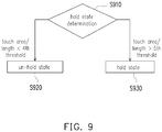
- the processor 150 before performing the aforementioned determination for the hold state (i.e. one of the sensors 110, 120 does not detect any object, or more than two touch points are detected by both sensors 110, 120), the processor 150 further determines whether the handheld device 100 is in a hold state (Step S910), that is to say, the processor 150 determines whether the handheld device 100 is hold by an object (e.g., finger, or clamp) by determining whether the total touch area or touch length detected on one of the first and second sides S1, S2 of the body 140 is less than a fourth threshold.
- an object e.g., finger, or clamp
- the processor 150 would determine the handheld device 100 is in the un-hold state (Step S920).
- the total touch length/area is a summation of touch length/area of the object (e.g., finger, or clamp) on one side S1 or S2.
- the handheld device 100 is placed on the hand, and the sensors 110, 120 may detect touch points TP131, TP 132 and TP 141 formed by the hand. However, the total length/area of the touch points TP131 and TP 132 on the first side S1 or the touch length/area of the touch point TP 141 on the second side S2 is less than the fourth threshold. Therefore, the processor 150 determines the handheld device 100 is in the un-hold state.
- the processor 150 would determine the handheld device 100 is the hold state (Step S930). Similarly, the aforementioned determinations of the un-hold state and the hold state would be performed every specific time interval (e.g. 200, 150, 300 microseconds). Since a user may not keep their force in the same level as one holds the handheld device 100, there is a tolerance between the fifth threshold and the fourth threshold.
- the processor 150 can further provide multiple applications according to the operational hand state.
- the processor 150 can display an operating interface corresponding to the first side S1 of the body 140 on the display 130; if the handheld device 100 is in the left hand state, the processor 150 can display an operating interface corresponding to the second side S2 of the body 140 on the display 130.
- the operating interface could be user interface (UI), window of virtual keyboard, toolbar, application, widget, setting, or app shortcuts.
- UI user interface
- the handheld device 100 is not in the left or right hand state, the operating interface would not be displayed by the display 130.
- a launcher application with an icon shortcut UI is shown on the display 130.
- the launcher application can be launched by touching corresponding shortcut or squeezing on two sensors 110 and 120.
- This launcher application includes an outer area OA and an inner area IA arranged with icons such as icons I1, 12, and these icons could be app shortcut, quick setting, function switch, or contact, etc.
- FIG. 11A with FIG. 2A if the handheld device 100 is determined in the right hand state as shown in FIGs.
- the outer and inner areas OA, IA would be presented at the position abutted the first side S1 of the body 140, so that the thumb of right hand can easier to touch the position on the display 130 corresponding to the icons of the icon shortcut UI.
- the handheld device 100 is determined in the left hand state as shown in FIGs. 6A, 6B , 8A and 8D , referring to FIGs. 2B and 10B , the outer and inner areas OA, IA would be presented at the position abutted the second side S2 of the body 140, so that the thumb of left hand can easier to touch the position on the display 130 corresponding to the icons of the icon shortcut UI.
- a user can use siding operation on the display 130 to modify the position of the outer and inner areas OA, IA of UI as shown in FIGs. 11A and 11B .
- the processor 150 detects that a sliding input SI1 from the right side to the left side of the figure on the display 130 for a certain distance, the sliding input SI1 is not applied on calendar C, and the horizontal component of movement of the sliding input SI1 is larger than a threshold.
- the processor 150 may display the outer and inner areas OA, IA at the position abutted the left side of the figure (i.e. near to side S2).
- the processor 150 may display the outer and inner areas OA, IA at the position abutted the right side of the figure (i.e. near to side S1) as shown in FIG. 11A .
- the processor 150 detects that a sliding input SI3 from the bottom toward top of the screen on a first area (e.g. semi-ring are of the outer area OA, or other areas expect for semicircle area of the inner area IA), the outer area OA would be rotated when the vertical moving distance of the sliding input is larger a threshold, and the inner area IA remains the same.
- the outer area OA rotates clockwise by 10 degrees if the vertical moving direction is upward and the vertical moving distance is 1 centimeter (larger than 0.5 centimeter).
- a touch point slides on a second area (e.g.
- the inner area IA would be rotated when the vertical moving distance of the sliding input is larger than a threshold, and the outer area OA remains the same.
- the outer and inner areas OA, IA can be rotated, respectively, on the basis of the operation on the corresponding operating area of the screen (i.e. the first and second areas).
- the icon shortcut UIs on the outer area OA and the inner area IA may be rotated simultaneously if the sliding input is applied on the area except for the area of the calendar C (or include the area of the calendar C) and the vertical moving distance of the sliding input is larger a threshold.
- the processor 150 may record usage frequencies of all icons on the icon shortcut UI, and the size, shape, brightness, color or pattern of the icons may be changed according to the usage frequencies. For example, if the usage frequency of the icon I1 is larger than 5 times, the size of the icon I1 would be increased 10%.
- the disclosure also provides a non-transitory computer readable recording medium, which records computer program to be loaded into a processor disposed in a handheld device having two sensors disposed on two sides thereof to execute the steps of the proposed method.
- the computer program is composed of a plurality of program instructions (e.g. an organization chart, establishing program instruction, a table approving program instruction, a setting program instruction, and a deployment program instruction). Once the program sections are loaded into the handheld device and executed by the same, the steps of the proposed method would be accomplished.
- the exemplary embodiments described above depicted an operating method and an electronic device thereof.
- the handheld device is configured to determine whether in the right or left hand state according to force comparison, distance comparison and/or number comparison between sensing data of the first and second sensors disposed on the left and right sides of the handheld device.
- Any type of operating interface can be presented on the display and located at the position corresponding to the compared result (the right or left hand state), so that the thumb of hand can easier to operate on the operating interface, and a better operating experience for one hand can be provided.
Landscapes
- Engineering & Computer Science (AREA)
- Theoretical Computer Science (AREA)
- General Engineering & Computer Science (AREA)
- Human Computer Interaction (AREA)
- Physics & Mathematics (AREA)
- General Physics & Mathematics (AREA)
- Computer Hardware Design (AREA)
- User Interface Of Digital Computer (AREA)
- Telephone Function (AREA)
- Position Input By Displaying (AREA)
Abstract
Description
- The present disclosure relates to a method for operating a handheld device, a handheld device, and a computer-readable recording medium thereof, and more particularly, relates to a handheld device being operated through sensors disposed on the sides of the handheld device.
- Handheld device such as mobile phone, tablet PC and the like are popular and being used in all kind of occasions. People may use the handheld device for playing multimedia, web browsing, navigation, gaming, and etc. On the other hand, in recent years, the display technology has been developed with a significant breakthrough, lots of manufactories trend to design handheld devices with slim bezel, so as to increase screen-to-body ratios of the handheld devices and provide better visual experience to users. However, many users like handheld devices with large screen, but they generally operate the handheld device with one hand, so that a part of the screen may not be touched with one hand because of hand size. In addition, software developers usually do not design user interfaces (UIs) of the handheld devices for a special purpose of one hand use, so that the user have to operate with two hands in some situation. Accordingly, one hand experience for handheld devices should be improved.
- Accordingly, the present disclosure is directed to a method for operating a handheld device, a handheld device, and a computer-readable recording medium thereof, which determine the handheld device is held by left hand or right hand, so as to provide a corresponding UI for a specific hand.
- In one of the exemplary embodiments, the handheld device at least includes, but not limited to, a body, a first sensor, a second sensor, and a processor. The first sensor is disposed on a first side of the body. The second sensor is disposed on a second side of the body different from the first side. The processor is coupled to the first and second sensors and configured to obtain sensing data of the first and second sensors, and to determine the handheld device is in a left hand state or a right hand state according to a compared result between sensing data of the first and second sensors, where the compared result includes a force comparison between forces applied on the first and second sides of the body, the first side of the body corresponds to the right hand state, and the second side of the body corresponds to the left hand state.
- According to one of the exemplary embodiments, the compared result comprises a number comparison between numbers of touch point detected by the first and second sensors and a distance comparison between distances between two touch points on the first and second sides of the body, and the processor is configured to, in response to the number comparison being the same, determine the handheld device is in the left hand state or the right hand state according to the distance comparison in response to the number of touch point detected by one of the first and second sensors being two, and to determine the handheld device is in the left hand state or the right hand state according to the force comparison in response to the number of touch point detected by one of the first and second sensors being one.
- According to one of the exemplary embodiments, the processor is configured to determine whether a force difference of the force comparison is larger than a force difference threshold to confirm the handheld device is in the left hand state or the right hand state.
- According to one of the exemplary embodiments, the processor is configured to determine whether a touch area or a touch length detected on one of the first and second sides of the body is larger than a first threshold in response to the force difference being not larger than the force difference threshold, to confirm the handheld device is in the left hand state or the right hand state.
- According to one of the exemplary embodiments, the handheld device further comprises a third sensor coupled to the processor. The processor is configured to determine an orientation of the body according to sensing data of the third sensor, and to determine the handheld device is in the left hand state or the right hand state according to the orientation of the body.
- According to one of the exemplary embodiments, the compared result comprises a number comparison between numbers of touch point detected by the first and second sensors, and the processor is configured to, in response the number comparison being different, determine the handheld device is in the left hand state or the right hand state according to a touch area or a touch length detected on the first side of the body and the force comparison in response to the number of touch point detected by the second sensor being larger than the number of touch point detected by the first sensor, and to determine the handheld device is in the left hand state or the right hand state according to a touch area or a touch length detected on the second side of the body and the force comparison in response to the number of touch point detected by the first sensor being larger than the number of touch point detected by the second sensor.
- According to one of the exemplary embodiments, the compared result comprises a number comparison between numbers of touch point detected by the first and second sensors. The processor is configured to determine the handheld device is in the left hand state or the right hand state according to a distance between two touch points on one of the first and second sides of the body in response the number comparison being different.
- According to one of the exemplary embodiments, the processor is configured to determine the operational hand state is not in a hold state in response to numbers of touch points detected on the first and second sides of the body being both larger than two.
- According to one of the exemplary embodiments, the processor is configured to determine the handheld device is not in a hold state in response to a number of touch point detected on one of the first and second sides of the body being zero or a total touch area or a total touch length detected on one of the first and second sides of the body being less than a second threshold. The hold state includes the left hand state and the right hand state.
- According to one of the exemplary embodiments, the processor is configured to determine the handheld device is in a hold state in response to a total touch area or a total touch length detected on one of the first and second sides of the body being larger than a third threshold and at least one touch point being detected on both of the first and second sides of the body, wherein the third threshold is larger than the second threshold.
- According to one of the exemplary embodiments, the handheld device further comprises a display coupled to the processor. The processor is configured to display an operating interface corresponding to the first side of the body on the display in response to the handheld device being in the right hand state, and display the operating interface corresponding to the second side of the body on the display in response to the handheld device being in the left hand state.
- In one of the exemplary embodiments, the method for operating a handheld device is provided. The handheld device includes, but not limited to, a body, a first sensor disposed on a first side of the body and a second sensor disposed on a second side of the body different from the first side. The method includes the following steps. Sensing data of the first and second sensors is obtained. The handheld device being in a left hand state or a right hand state is determined according to a compared result between sensing data of the first and second sensors, where the compared result includes a force comparison between forces applied on the first and second sides of the body, the first side of the body corresponds to the right hand state, and the second side of the body corresponds to the left hand state.
- In one of the exemplary embodiments, the non-transitory computer readable recording medium records computer program to be loaded by a processor of a handheld device having two sensors disposed on two sides thereof to execute the aforementioned method.
- To make the above features and advantages of the disclosure more comprehensible, several embodiments accompanied with drawings are described in detail as follows.
- It should be understood, however, that this Summary may not contain all of the aspects and embodiments of the present disclosure, is not meant to be limiting or restrictive in any manner, and that the invention as disclosed herein is and will be understood by those of ordinary skill in the art to encompass obvious improvements and modifications thereto.
- The accompanying drawings are included to provide a further understanding of the disclosure, and are incorporated in and constitute a part of this specification. The drawings illustrate embodiments of the disclosure and, together with the description, serve to explain the principles of the disclosure.
-
FIG. 1 is a block diagram illustrating a handheld device according to one of the exemplary embodiments of the disclosure. -
FIG. 2A and2B are schematic diagrams illustrating a handheld device according to one of the exemplary embodiments of the disclosure. -
FIG. 3 is a flowchart illustrating a method for operating the handheld device according to one of the exemplary embodiments of the disclosure. -
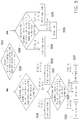
FIG. 4 is a flowchart illustrating a procedure of the handheld device for determining an operational hand state according to one of the exemplary embodiments of the disclosure. -
FIG. 5 is a flowchart illustrating a procedure of the handheld device for determining the operational hand state according to one of the exemplary embodiments of the disclosure. -
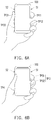
FIG. 6A and 6B are schematic diagrams illustrating the handheld device is held in different way. -
FIG. 7 is a flowchart illustrating a procedure of the handheld device for determining the operational hand state according to one of the exemplary embodiments of the disclosure. -
FIG. 8A ∼ 8D are schematic diagrams illustrating the handheld device is held in different way. -
FIG. 9 is a flowchart illustrating a procedure of the handheld device for determining the handheld device is in a un-hold state or a hold state according to one of the exemplary embodiments of the disclosure. -
FIG. 10 is a schematic diagram illustrating the handheld device is in a un-hold state. -
FIG. 11A and 11B is schematic diagrams illustrating an operating interface corresponding to different sides of the handheld device according to one of the exemplary embodiments of the disclosure. - Reference will now be made in detail to the present preferred embodiments of the disclosure, examples of which are illustrated in the accompanying drawings. Wherever possible, the same reference numbers are used in the drawings and the description to refer to the same or like parts.
- Referring to
FIG. 1, FIG. 1 is a block diagram illustrating ahandheld device 100 according to one of the exemplary embodiments of the disclosure. Thehandheld device 100 at least includes, but not limited to, afirst sensor 110, asecond sensor 120, adisplay 130 and aprocessor 150. Thehandheld device 100 could be mobile phone, tablet PC, camera, handheld game console, multimedia player, etc. - Referring to
FIGs. 1 ,2A and2B , thefirst sensor 110 is disposed on a first side S1 ofbody 140 of thehandheld device 100, and thesecond sensor 120 is disposed on a second side S2 of thebody 140, where the second side S2 is opposite to the first side S1. In this embodiment, the first side S1 of thebody 140 is the right side of thebody 140, and the second side S2 is the left side of thebody 140. Thefirst sensor 110 and thesecond sensor 120 could be capacitive sensor, resistive sensor, piezoelectric sensor, electromagnetic sensor, other type of pressure sensors, or a combination of aforesaid sensors, to detect the presence of objects (e.g. finger, or clamp) being placed on the first side S1 and the second side S2, and generate sensing data including touch position, force or pressure related raw data. - It should be noticed that, the first and
second sensor sensor body 140 with single type sensor or various type of pressure sensors. If the sensing elements are arranged in one-dimension, for example, the arranged sensing elements form an line extended from the top to the button of side S1 or/and S2, the sensing data of the sensing elements can be used for detecting a touch length of object (e.g. finger, clamp, or other object). If the sending elements are arranged in two-dimension, for example, the arranged sensing elements form an rectangle shape having four sides near to edges of side S1 or/and S2, the sensing data of the sensing elements can be used for detecting a touch area of object (e.g. finger, clamp, or other object). It should be noticed that, the shapes formed by the arranged sensing elements on sides S1 and S2 can be modified according to actual requirement, and the exemplary embodiment of the disclosure is not limited thereto. - The
display 130 could be a liquid crystal display (LCD), light emitting diode (LED), organic light emitting diode (OLED), or other type of display. Two sides of thedisplay 130 locates near the first and second sides S1, S2 of thebody 140 as shown inFIGs 2A and2B . In one exemplary embodiment, thedisplay 130 may be integrated with touch panel (including touch sensor such as resistive touch sensor, capacitive touch sensor, optic touch sensor or the likes), so as to provide display and touch sensing functions. - The
processor 150 is coupled to thefirst sensor 110, thesecond sensor 120 anddisplay 140. Theprocessor 150 may be implemented by using a programmable unit, such as a central processing unit (CPU), a micro-processor, a micro-controller, a digital signal processing (DSP) chip, a field programmable gate array (FPGA), and so on. The function of theprocessor 150 may also be implemented by an independent electronic device or an integrated circuit (IC), and the operation of theprocessor 150 may also be implemented by software. Theprocessor 150 is programmed to execute the functions or steps that would be described below. - In order to make the operation process of the embodiment of the disclosure more comprehensible, several embodiments are provided below to describe in detail the operations of the
handheld device 100 in the embodiment of the disclosure. -
FIG. 3 is a flowchart of a method for operating thehandheld device 100 according to one of exemplary embodiments of the disclosure. Referring toFIG. 3 , the method of this embodiment is adapted for thehandheld device 100 ofFIGs. 1 ,2A and2B . In the following paragraphs, the method of this embodiment of the disclosure is described first with reference to the components of thehandheld device 100. Nevertheless, the processes of this method may be adjusted according to the actual needs and thus are not limited to the following. - The
processor 150 obtains sensing data of the first andsecond sensors 110, 120 (Step S310). Theprocessor 150 may analyze the raw data (such as strength value and corresponding position) included in the sensing data, to determine the number, position, force and pressure of objects (e.g. finger or clamp) detected or applied on two sides S1, S2 of thebody 140. - Then, the
processor 150 determines thehandheld device 100 is in a left hand state or a right hand state according to a compared result between sensing data of the first andsecond sensors 110, 120 (Step S330). Specifically, in general, when user holds thebody 140 of thehandheld device 100 by his/her right hand, the thumb and/or palm of the right hand abuts against the first side S1 of thebody 140, and at least one of the other fingers of the right hand abuts against the second side S2 of thebody 140. On the other hand, when the user holds thebody 140 by his/her left hand, the thumb and/or palm of the left hand abuts against the second side S2 of thebody 140, and at least one of the other fingers of the left hand abuts against the first side S1 of thebody 140. If a situation that thebody 140 is held by the right hand is detected, theprocessor 140 determines an operational hand state is the right hand state (i.e., thehandheld device 100 is in the right hand state). If another situation that thebody 140 is held by the left hand is detected, theprocessor 140 determines the operational hand state is the left hand state (i.e., thehandheld device 100 is in the left hand state). In addition, the user usually uses the thumb to operate the handheld device 100 (or touch the display 140) no matter which hand he/she uses. Thus, in this embodiment, the first side S1 of thebody 140 is defined as corresponding to the right hand state because the thumb of right hand abuts against the first side S1. The second side S2 of thebody 140 is defined as corresponding to the left hand state because the thumb of the left hand abuts against the second side S2. In addition, the compared result may include one or any combination of number comparison, force comparison, distance comparison and touch lengths/areas of touch point on two sides S1 and S2, which would be discussed in detail later. - In order to provide one hand experience, the subsequent step is to detect that the
handheld device 100 is held by which hand of user. Referring toFIG. 4, FIG. 4 is a flowchart illustrating a procedure of thehandheld device 100 for determining the operational hand state according to one of the exemplary embodiments of the disclosure. It is assumed thatprocessor 150 detects the operational hand state is a hold state (i.e., thebody 140 is held by hand), and the determination of the hold state would be described below in detail. In general, when thehandheld device 100 is held by one hand, the numbers of touch point, distances between two touch points, touched areas (or touch length) and applied forces on the two side S1, S2 of thebody 140, which are detected by the first andsecond sensors handheld device 100. - The
processor 150 determines whether the number of touch point detected by one of the first andsecond sensors sensors handheld device 100 is held by one hand, one of the first andsecond sensors body 140 against which a thumb and/or a palm abuts, where the two touch points may be generated by the thumb and/or a part of palm. If none of fingers is detected on one of the sides S1, S2 of the body by the first orsecond sensor body 140 by the first andsecond sensors handheld device 100 is not held by hand, so that theprocessor 150 determine the operational hand state is a un-hold state (i.e., thehandheld device 100 is not in a hold state, where the hold state includes the left hand state and the right hand state) (Step S415). For example, thebody 140 is held by a mobile holder, so that more than two touch points are detected on two side S1, S2. Thebody 140 is merely rested or abutted against hand, but is not held by hand, so that at least one of thesensors sensors body 140 are not both larger than two, theprocessor 150 determine the operational hand state is still the hold state. In other words, if the numbers of touch points detected on both sides S1, S2 both are between 1 and 2, or if the number of touch point detected on one side S1/S2 is larger than two and the number of touch point detected on the other side S2/S1 is less than three, the operational hand state is still in the hold state. - Then, the
processor 150 determines whether the number of touch point detected by one of the first andsecond sensors handheld device 100 is held by one hand, one of the first andsecond sensors body 140 opposite to the other side ofbody 140 against which a thumb abuts, where the touch points may be generated by index finger, middle finger, ring finger or little finger. If more than two fingers are detected on the first side S1 of thebody 140, theprocessor 150 determines thehandheld device 100 is in the left hand state; if more than two fingers are detected on the second side S2 of thebody 140, theprocessor 150 determines thehandheld device 100 is in the right hand state (Step S425). - On the other hand, if the number of touch point of the first or
second sensor processor 140 determines whether the numbers of touch point detected by the first andsecond sensors body 140 is zero (Step S430)? Different compared results would lead the step into different determination procedures. If the number comparison of the compared result is that the number difference is zero or the numbers are the same (e.g. the numbers of touch point detected by the first andsecond sensors processor 150 would determines the operational hand state is the left or right hand state according to the number of touch point, pressure (or force) on twosensors sensor 110, 120 (Step S435, it is called a first determination procedure). - Referring to
FIG. 5 , in the first determination procedure (i.e. in response to the number comparison being the same), theprocessor 150 would determine whether the number of touch point detected by both first andsecond sensors second sensors processor 150 would determine thehandheld device 100 is in the left hand state or the right hand state according to the distance comparison (e.g. the difference between distance between two touch points on the first side S1 and distance between two touch points on the second side S2) (Step S520). It is assumed that, when thehandheld device 100 is held by one hand, a first distance between one position against which the thumb abuts and another position against which the palm abuts may be larger than a second distance between any two positions against which the other two neighboring fingers abut. Therefore, if the distance comparison is that the distance D2 between two touch points on the first side S2 is larger than the distance D1 between two touch points on the second side S1 or the subtraction of the distance D1 from the distance D2 is larger than a threshold TD, theprocessor 150 determines thehandheld device 100 is in the left hand state (Step S530); if the distance comparison is that the distance between two touch points on the second side S1 is larger than the distance between two touch points on the first side S2 or the subtraction of the distance D2 from the distance D1 is larger than the threshold TD, theprocessor 150 determines thehandheld device 100 is in the right hand state (Step S540). - If the subtraction of the distance D1 from the distance D2 or the subtraction of the distance D2 from the distance D1 is not larger than the threshold TD, the
processor 150 may further determine whether the force difference of the force comparison between two forces F1, F2 applied on two sides S1 and S2 is larger than a force difference threshold TF to determine thehandheld device 100 is in the left hand state or the right hand state (Step S521). If the force difference is larger than the force difference threshold TF (i.e. F1-F2>TF) or the force F1 applied on the first side S1 is larger than the force F2 applied on the second side S2 (i.e. F1>F2), theprocessor 150 would determine that thehandheld device 100 is in the left hand state (Step S523). If the force difference is larger than the force difference threshold TF (i.e. F2-F1>TF) or the force F2 applied on the second side S2 is larger than the force F1 applied on the first side S1 (i.e. F2>F1), theprocessor 150 would determine that thehandheld device 100 is in the right hand state (Step S527). - It should be noticed that, in the Step S521, because there are two forces applied on both sides S1, S2 of the
body 140, theprocessor 150 can determine one force on each side S1/S2 for the force comparison. For example, theprocessor 150 may use the maximum force detected on side S1 to compare with the maximum force detected on the side S2. Alternatively, theprocessor 150 may use the average force detected on side S1 to compare with the average force detected on the side S2. - However, if the force difference is not larger than the force difference threshold TF (i.e. F1-F2< TF or F2-F1< TF), the
processor 150 use other rules to determine the hold state (Step S525). There are multiple rules, in one exemplary embodiment, if the force difference is less than the force difference threshold TF, theprocessor 150 can further determine whether a touch area or a touch length detected on one of the first and second sides S1, S2 of thebody 140 is larger than a first threshold (e.g. 350 or 400 square millimetre, 60 or 63 millimetres) to confirm thehandheld device 100 is in the left hand state or the right hand state. In general, the touch area of the thumb and/or the palm is larger than the other fingers. Therefore, if the touch area or the touch length detected on the first side S1 of the body is larger than the first threshold, theprocessor 150 determines thehandheld device 100 is in the right hand state; if the touch area or the touch length detected on the second side S2 of the body is larger than the first threshold, theprocessor 150 determines thehandheld device 100 is in the left hand state. - In still other exemplary embodiment, the
handheld device 100 may further include a third sensor (not shown) coupled to theprocessor 150. The third sensor could be a g-sensor, a magnetic sensor, an accelerator, or other sensors that provide sensing data regarding to the orientation of thehandheld device 100, so that theprocessor 150 may determine the orientation of thebody 140 according to the sensing data of the third sensor. If the force difference is less than the force difference threshold TF, theprocessor 150 can further determine thehandheld device 100 is in the left hand state or the right hand state according to the orientation of thebody 140 if the force difference is not larger than the force difference threshold TF. Based on hand-hold posture, when a user holds thehandheld device 100 by the right or left hand and watch the screen of thedisplay 130, the tilt degrees relative to x and z axis can be used to determine that the user hold thehandheld device 100 by the right or left hand to watch the screen. For example, if the orientation of thebody 140 is toward the first side S1 of the body 140 (e.g. value of x axis is negative), theprocessor 150 determines the operational hand state is the left hand state. If the orientation of thebody 140 is toward the second side S2 of the body 140(e.g. value of x axis is positive), theprocessor 150 determines the operational hand state is the right hand state. - In the following, an example for two touch points detected by both two
sensors FIG. 6A is schematic diagram illustrating the handheld device is held by a left hand. Referring toFIG. 6A , the index finger, middle finger and ring finger of the left hand abut against side S1. It assumed that the ring finger does not cover on thefirst sensor 110 of thehandheld device 100, and theprocessor 150 would detect two touch points TP11 and TP12 on the side S1. In addition, the thumb and palm abut against side S2, and theprocessor 150 detects two touch points TP21 and TP22. Referring toFIGs. 5 and6A , because there are two touch points TP11 and TP12 on the side S1 and two touch points TP21 and TP22 on the side S2, theprocessor 150 would determine the distance comparison in step S520. Because the distance comparison is that the distance D2 between the touch points TP21 and TP22 is larger than the distance D1 between the touch points TP11 andTP 12, theprocessor 150 would determine thehandheld device 100 is in the left hand state (Step S530). - On the other hand, if the number of touch point detected by both first and
second sensors processor 150 would determine thehandheld device 100 is in the left hand state or the right hand state according to the force comparison (i.e. the force comparison between force F1 applied on the first side S1 and another force F2 applied on the second side S2) (Step S550). It is assumed that, when thehandheld device 100 is held by one hand, the force applied by the index finger or middle finger may be larger than the force applied by the thumb or the palm. Therefore, if the force comparison is that the force F1 applied on the second side S1 is larger than the force F2 applied on the first side S2 (i.e. F1>F2) or the force F1 applied on the first side S1 is larger than the force F2 applied on the second side S2 (i.e. F1-F2>TF), theprocessor 150 determines thehandheld device 100 is in the left hand state (Step S560); if the force comparison is that the force F2 applied on the first side S2 is larger than the force F1 applied on the second side S1 (i.e. F2>F1) or the force difference is larger than the force difference threshold TF (i.e. F2-F1>TF), theprocessor 150 determines thehandheld device 100 is in the right hand state (Step S570). - However, if the force difference is not larger than the force difference threshold TF (i.e. F1-F2< TF or F2-F1< TF), the
processor 150 use other rules to determine the hold state (Step S555). It should be noticed that, the rules implemented in the step S555 can be referred to the embodiments of step S525 such as the determinations of touch length/area and orientation, and the corresponding description would be omitted. - In the following, an example for one touch point detected by both two
sensors FIG. 6B is schematic diagram illustrating the handheld device is held by a left hand. Referring toFIG. 6B , the index finger, middle finger and ring finger of the left hand abut against side S1. It assumed that the ring finger does not cover on thefirst sensor 110 of thehandheld device 100, two touch points TP31 and TP32 is too close (for example, the distance between two touch points TP31 and TP32 is less than 1 centimeter), so that theprocessor 150 would consider that only one touch point TP3 on the side S1. In addition, the palm abuts against side S2, the thumb does not touch thehandheld device 100, and theprocessor 150 detects a touch point TP4. Referring toFIGs. 5 and6B , because there are one touch point TP3 on the side S1 and one touch point TP4 on the side S2, theprocessor 150 would determine the force comparison in step S550. Because the force comparison is that the force F1 applied on the touch point TP3 is larger than the force F2 applied on the touch point TP4, theprocessor 150 would determine thehandheld device 100 is in the left hand state (Step S560). - In some exemplary embodiments, the aforementioned conditions (the force difference, the touch area, the touch length, and the orientation of the body 140) may be provided with weights, and the
processor 150 can determine the operational hand state is the right or left hand state according to the weight average or the weight sum of the values of these conditions and corresponding weights. - Back to
FIG.4 , if the number comparison is that the number difference is not zero or the numbers are different (i.e. the numbers of touch point detected by the first andsecond sensors processor 150 would determines whether thehandheld device 100 is in the left or right hand state according to touch point distribution, touch length/area, pressure (or force) on twosensors sensor 110, 120 (Step S440, it is called a second determination procedure). - Referring to
FIG. 7 , in the second determination procedure (i.e. in response to the number comparison being different), theprocessor 150 would determine whether the number of touch point detected by thesecond sensor 120 is larger than the number of touch point detected by the first sensor 110 (i.e. the number of fingers detected by thesecond sensor 120 is two, and the number of finger detected by thefirst sensor 110 is one) or the number of touch point detected by thefirst sensor 110 is larger than the second sensor 120 (i.e. the number of fingers detected by thefirst sensor 110 is two, and the number of finger detected by thesecond sensor 120 is one) according to the touch point distribution (Step S710). If the number of touch point detected by thesecond sensor 120 is larger than the number of touch point detected by the first sensor 110 (i.e., the numbers of touch point are 1 on the first side S1 and 2 on the second side S2), theprocessor 150 determine thehandheld device 100 is in the left hand state or the right hand state according to the touch area (or touch length) detected on the first side S1 of thebody 140 and the force comparison (Step S720). According to the test result of actual operation, if the touch area or touch length detected on the first side S1 of thebody 140 is larger than a second threshold and the force comparison is that the force applied on the first side S1 of thebody 140 is larger than the force applied on the second side S2, theprocessor 150 determines thehandheld device 100 is in the left hand state (Step S730); otherwise, theprocessor 150 determines thehandheld device 100 is in the right hand state (Step S740). - In another exemplary embodiment, the
processor 150 may determine thehandheld device 100 is in the left hand state or the right hand state according to the distance between two touch points on the second side S2 of the body 140 (S720). If the distance between two touch points on the second side S2 of thebody 140 is larger a distance threshold TD, theprocessor 150 determines thehandheld device 100 is in the left hand state (Step S730); otherwise, theprocessor 150 determines thehandheld device 100 is in the right hand state (Step S740). - For example,
FIG. 8A is schematic diagram illustrating the handheld device is held by a left hand. Referring toFIG. 8A , the index finger and middle finger of the left hand abut against side S1. It assumed that two touch points TP51 and TP52 is too close (for example, the distance between two touch points TP51 and TP52 is less than 0.8 centimeter), so that theprocessor 150 would consider that only one touch point TP5 on the side S1. In addition, the thumb and palm abut against side S2, and theprocessor 150 detects two touch points TP61 and TP62. Referring toFIGs. 7 and8A , because there are one touch point TP5 on the side S1 and two touch points TP61 and TP62 on the side S2, theprocessor 150 would determine the touch length/area and the force comparison in step S720. Because the touch length (or touch area) of the touch TP5 on side S1 is larger than second threshold and the force comparison is that the force F1 applied on the touch point TP5 is larger than two forces F2 applied on the touch points TP61 and TP62, or because the distance D2 between the touch points TP61 and TP62 is larger than the distance threshold TD, theprocessor 150 would determine thehandheld device 100 is in the left hand state (Step S730). -
FIG. 8B is schematic diagram illustrating the handheld device is held by a right hand. Referring toFIG. 8B , the index finger and middle finger of the right hand abut against side S2, and theprocessor 150 detects two touch points TP81 and TP82 on the side S2. In addition, the palm abuts against side S1, the thumb does not touch thehandheld device 100, and theprocessor 150 detects one touch points TP7. Referring toFIGs. 7 and8B , because there are one touch point TP7 on the side S1 and two touch points TP81 and TP82 on the side S2, theprocessor 150 would determine the touch length/area and the force comparison in step S720. Although the touch length/area of the touch point TP7 is larger than the second threshold, but the force comparison is that the force F1 applied on the touch point TP7 is less than one force F2 applied on the touch point TP81 or TP82. Therefore, the compared result is not conformed to the left hand state, and theprocessor 150 would determine thehandheld device 100 is in the right hand state (Step S740). - On the other hand, back to
FIG. 7 , if the number of touch point detected by thefirst sensor 110 is larger than the number of touch point detected by the second sensor 120 (i.e., the numbers of touch point are 2 on the first side S1 and 1 on the second side S2), theprocessor 150 determine thehandheld device 100 is in the left hand state or the right hand state according to the touch area or touch length detected on the second side S2 of thebody 140 and the force comparison (Step S750). According to the test result of actual operation, if the touch area or touch length detected on the second side S2 of thebody 140 is larger than a third threshold and the force comparison is that the force applied on the second side S2 of thebody 140 is larger than the first side S1, theprocessor 150 determines thehandheld device 100 is in the right hand state (Step S760); otherwise, theprocessor 150 determines thehandheld device 100 is in the left hand state (Step S770). - In another exemplary embodiment, the
processor 150 may further determine thehandheld device 100 is in the left hand state or the right hand state according to the distance between two touch points on the first side S1 of the body 140 (Step S750). If the distance D1 between two touch points on the first side S1 of thebody 140 is larger the distance threshold TD, theprocessor 150 determines thehandheld device 100 is in the right hand state (Step S760); otherwise, theprocessor 150 determines the handheld device is in the left hand state (S770). - For example,
FIG. 8C is schematic diagram illustrating the handheld device is held by a right hand. Referring toFIG. 8C , the index finger, middle finger and ring finger of the right hand abut against side S2. It assumed that two touch points TP101 and TP102 is too close (for example, the distance between two touch points TP101 and TP102 is less than 0.9 centimeter), and the ring finger does not cover thesecond sensor 120, so that theprocessor 150 would consider that only one touch point TP10 on the side S2. In addition, the thumb and palm abut against side S1, and theprocessor 150 detects two touch points TP91 and TP92. Referring toFIGs. 7 and8C , because there are two touch points TP91 and TP92 on the side S1 and one touch point TP6 on the side S2, theprocessor 150 would determine the touch length/area and the force comparison in step S750. Because the touch length/area on side S2 is larger than the third threshold and the force comparison is that the force F2 applied on the touch point TP10 is larger than two forces F1 applied on the touch points TP91 and TP92, or because the distance D1 between the touch points TP91 and TP92 is larger than the distance threshold TD, theprocessor 150 would determine thehandheld device 100 is in the right hand state (Step S760). -
FIG. 8D is schematic diagram illustrating the handheld device is held by a right hand. Referring toFIG. 8D , the index finger, middle finger and ring finger of the right hand abut against side S1, the ring finger does not cover thefirst sensor 110, and theprocessor 150 detects two touch points TP111 and TP112 on the side S1. In addition, the palm abuts against side S2, the thumb does not touch thehandheld device 100, and theprocessor 150 detects one touch points TP121. Referring toFIGs. 7 and8D , because there are two touch points TP111 and TP112 on the side S1 and one touch point TP121 on the side S2, theprocessor 150 would determine the touch length/area and the force comparison in step S750. Although the touch length/area of the touch point TP121 is larger than the third threshold, but the force comparison is that the force F2 applied on the touch point TP121 is less than one force F1 applied on the touch point TP111 or TP112, or because the distance D1 between the touch points TP111 and TP112 is less than the distance threshold TD, theprocessor 150 would determine thehandheld device 100 is in the left hand state (Step S770). - It should be noticed that, the aforementioned determination of the
handheld device 100 is in the left hand state or the right hand state would be performed every specific time interval (e.g. 200, 150, 300 microseconds) when the operational hand state is still the hold state. Similarly, theprocessor 150 may check whether the operational hand state is the un-hold state or not in the hold state. - In one embodiment, referring to
FIG. 9 , before performing the aforementioned determination for the hold state (i.e. one of thesensors sensors 110, 120), theprocessor 150 further determines whether thehandheld device 100 is in a hold state (Step S910), that is to say, theprocessor 150 determines whether thehandheld device 100 is hold by an object (e.g., finger, or clamp) by determining whether the total touch area or touch length detected on one of the first and second sides S1, S2 of thebody 140 is less than a fourth threshold. If the total touch area or touch length detected on one of the first and second sides S1, S2 of thebody 140 is less than a fourth threshold (less than the first, second and third thresholds), theprocessor 150 would determine thehandheld device 100 is in the un-hold state (Step S920). The total touch length/area is a summation of touch length/area of the object (e.g., finger, or clamp) on one side S1 or S2. - For example, please refer to
FIG. 10 . Thehandheld device 100 is placed on the hand, and thesensors processor 150 determines thehandheld device 100 is in the un-hold state. - On the other hand, if the total touch area or total touch length detected on one of the first and second sides S1, S2 of the
body 140 is larger than a fifth threshold (larger than the fourth threshold), theprocessor 150 would determine thehandheld device 100 is the hold state (Step S930). Similarly, the aforementioned determinations of the un-hold state and the hold state would be performed every specific time interval (e.g. 200, 150, 300 microseconds). Since a user may not keep their force in the same level as one holds thehandheld device 100, there is a tolerance between the fifth threshold and the fourth threshold. - In addition, after the right or left hand state is determined, the
processor 150 can further provide multiple applications according to the operational hand state. In one exemplary embodiment, if thehandheld device 100 is in the right hand state, theprocessor 150 can display an operating interface corresponding to the first side S1 of thebody 140 on thedisplay 130; if thehandheld device 100 is in the left hand state, theprocessor 150 can display an operating interface corresponding to the second side S2 of thebody 140 on thedisplay 130. The operating interface could be user interface (UI), window of virtual keyboard, toolbar, application, widget, setting, or app shortcuts. On the other hand, if thehandheld device 100 is not in the left or right hand state, the operating interface would not be displayed by thedisplay 130. - For example, referring to
FIG. 11A , a launcher application with an icon shortcut UI is shown on thedisplay 130. The launcher application can be launched by touching corresponding shortcut or squeezing on twosensors FIG. 11A withFIG. 2A , if thehandheld device 100 is determined in the right hand state as shown inFIGs. 8B and8C , the outer and inner areas OA, IA would be presented at the position abutted the first side S1 of thebody 140, so that the thumb of right hand can easier to touch the position on thedisplay 130 corresponding to the icons of the icon shortcut UI. On the other hand, if thehandheld device 100 is determined in the left hand state as shown inFIGs. 6A, 6B ,8A and8D , referring toFIGs. 2B and10B , the outer and inner areas OA, IA would be presented at the position abutted the second side S2 of thebody 140, so that the thumb of left hand can easier to touch the position on thedisplay 130 corresponding to the icons of the icon shortcut UI. - In addition, there many operating methods for the launcher application. A user can use siding operation on the
display 130 to modify the position of the outer and inner areas OA, IA of UI as shown inFIGs. 11A and 11B . For example, referring toFIG. 11A if theprocessor 150 detects that a sliding input SI1 from the right side to the left side of the figure on thedisplay 130 for a certain distance, the sliding input SI1 is not applied on calendar C, and the horizontal component of movement of the sliding input SI1 is larger than a threshold. Then, referring toFIG. 11B , theprocessor 150 may display the outer and inner areas OA, IA at the position abutted the left side of the figure (i.e. near to side S2). On the other hand, if the outer and inner areas OA, IA are located at the position as shown in 11B, and theprocessor 150 detects that a slide input SI2 from the left side to the right side of the figure on thedisplay 130 for a certain distance, the sliding input SI2 is not applied on calendar C, and the horizontal component of movement of the sliding input S2 is larger than a threshold, theprocessor 150 may display the outer and inner areas OA, IA at the position abutted the right side of the figure (i.e. near to side S1) as shown inFIG. 11A . - Furthermore, if the
processor 150 detect that a sliding input SI3 from the bottom toward top of the screen on a first area (e.g. semi-ring are of the outer area OA, or other areas expect for semicircle area of the inner area IA), the outer area OA would be rotated when the vertical moving distance of the sliding input is larger a threshold, and the inner area IA remains the same. For example, the outer area OA rotates clockwise by 10 degrees if the vertical moving direction is upward and the vertical moving distance is 1 centimeter (larger than 0.5 centimeter). On the other hand, if theprocessor 150 detect that a touch point slides on a second area (e.g. semicircle area of the inner area IA, or other areas expect for semi-ring are of the outer area OA) different from the first area, the inner area IA would be rotated when the vertical moving distance of the sliding input is larger than a threshold, and the outer area OA remains the same. In other words, the outer and inner areas OA, IA can be rotated, respectively, on the basis of the operation on the corresponding operating area of the screen (i.e. the first and second areas). In still another example, the icon shortcut UIs on the outer area OA and the inner area IA may be rotated simultaneously if the sliding input is applied on the area except for the area of the calendar C (or include the area of the calendar C) and the vertical moving distance of the sliding input is larger a threshold. - Moreover, the
processor 150 may record usage frequencies of all icons on the icon shortcut UI, and the size, shape, brightness, color or pattern of the icons may be changed according to the usage frequencies. For example, if the usage frequency of the icon I1 is larger than 5 times, the size of the icon I1 would be increased 10%. - The disclosure also provides a non-transitory computer readable recording medium, which records computer program to be loaded into a processor disposed in a handheld device having two sensors disposed on two sides thereof to execute the steps of the proposed method. The computer program is composed of a plurality of program instructions (e.g. an organization chart, establishing program instruction, a table approving program instruction, a setting program instruction, and a deployment program instruction). Once the program sections are loaded into the handheld device and executed by the same, the steps of the proposed method would be accomplished.
- In summary, the exemplary embodiments described above depicted an operating method and an electronic device thereof. The handheld device is configured to determine whether in the right or left hand state according to force comparison, distance comparison and/or number comparison between sensing data of the first and second sensors disposed on the left and right sides of the handheld device. Any type of operating interface can be presented on the display and located at the position corresponding to the compared result (the right or left hand state), so that the thumb of hand can easier to operate on the operating interface, and a better operating experience for one hand can be provided.
- It will be apparent to those skilled in the art that various modifications and variations can be made to the structure of the present disclosure without departing from the scope or spirit of the disclosure. In view of the foregoing, it is intended that the present disclosure cover modifications and variations of this disclosure provided they fall within the scope of the following claims and their equivalents.
Claims (15)
- A handheld device, comprising:a body;a first sensor, disposed on a first side of the body;a second sensor, disposed on a second side of the body different from the first side; anda processor, coupled to the first and second sensors, and configured for:obtaining sensing data of the first and second sensors; anddetermining the handheld device is in a left hand state or a right hand state according to a compared result between sensing data of the first and second sensors, wherein the compared result comprises a force comparison between forces applied on the first and second sides of the body.
- The handheld device according to claim 1, wherein the compared result comprises a number comparison between a number of at least one touch point detected by the first sensor and a number of at least one touch point detected by the second sensor.
- The handheld device according to claim 2, wherein the processor is configured for:determining the handheld device is in the left hand state or the right hand state according to a distance comparison between a distance between two touch points on the first side and a distance between two touch points on the second side in response to the number of the at least one touch point detected by the first sensor and the number of the at least one touch point detected by the second sensor being two; anddetermining the handheld device is in the left hand state or the right hand state according to the force comparison in response to the number of the at least one touch point detected by the first sensor and the number of the at least one touch point detected by the second sensor being one.
- The handheld device according to claim 3, wherein the processor is configured for:
determining whether a force difference of the force comparison is larger than a force difference threshold or the force applied on the first sensor is larger than the force applied on the second sensor to confirm the handheld device is in the left hand state or the right hand state. - The handheld device according to claim 4, wherein the processor is configured for:
determining whether a touch area or a touch length detected on one of the first and second sides of the body is larger than a first threshold in response to the force difference being not larger than the force difference threshold, to confirm the handheld device is in the left hand state or the right hand state. - The handheld device according to claim 2, wherein the processor is configured for:determining the handheld device is in the left hand state or the right hand state according to a touch area or a touch length detected on the first side of the body and the force comparison in response to the number of the at least one touch point detected by the second sensor being larger than the number of the at least one touch point detected by the first side; anddetermining the handheld device is in the left operational hand state or the right hand state according to the touch area or the touch length detected on the second side of the body and the force comparison in response to the number of the at least one touch point detected by the first sensor being larger than the number of the at least one touch point detected by the second side.
- The handheld device according to claim 2, wherein the processor is configured for:
determining the handheld device is in the left hand state or the right hand state according to the distance between two touch points on the first or second side being larger than a second threshold in response to the number of the at least one touch point detected by the second sensor and the number of the at least one touch point detected by the first side being different. - The handheld device according to claim 1, further comprising:a display, coupled to the processor, whereinthe processor is configured for:displaying an operating interface corresponding to the first side of the body on the display in response to the handheld device being in the right hand state; anddisplaying the operating interface corresponding to the second side of the body on the display in response to the handheld device being in the left hand state.
- A method for operating a handheld device, wherein the handheld device comprises a body, a first sensor disposed on a first side of the body and a second sensor disposed on a second side of the body different from the first side, the method comprising:obtaining sensing data of the first and second sensors; anddetermining the handheld device is in a left hand state or a right hand state according to a compared result between sensing data of the first and second sensors, wherein the compared result comprises a force comparison between forces applied on the first and second sides of the body.
- The method according to claim 9, wherein the compared result comprises a number comparison between a number of at least one touch point detected by the first sensor and a number of at least one touch point detected by the second sensor.
- The method according to claim 10, comprises:determining the handheld device is in the left hand state or the right hand state according to a distance comparison between a distance between two touch points on the first side and a distance between two touch points on the second side in response to the number of the at least one touch point detected by the first sensor and the number of the at least one touch point detected by the second sensor being two; anddetermining the handheld device is in the left hand state or the right hand state according to the force comparison in response to the number of the at least one touch point detected by the first sensor and the number of the at least one touch point detected by the second sensor being one.
- The method according to claim 11, further comprising:
determining whether a force difference of the force comparison is larger than a force difference threshold or the force applied on the first sensor is larger than the force applied on the second sensor to confirm the handheld device is in the left hand state or the right hand state. - The method according to claim 12, further comprising:
determining whether a touch area or a touch length detected on one of the first and second sides of the body is larger than a first threshold in response to the force difference being not larger than the force difference threshold, to confirm the handheld device is in the left hand state or the right hand state. - The method according to claim 10, comprises:determining the handheld device is in the left hand state or the right hand state according to the force comparison and a touch area or a touch length detected on one of the first and second side applied with the larger one of the forces applied on the first and second sides in response to the number of the at least one touch point detected by the second sensor and the number of the at least one touch point detected by the first side being different; ordetermining the handheld device is in the left hand state or the right hand state according to the distance between two touch points on the first or second side being larger than a second threshold in response to the number of the at least one touch point detected by the second sensor and the number of the at least one touch point detected by the first side being different;.
- A non-transitory computer readable recording medium, recording computer program to be loaded by a handheld device having two sensors disposed on two sides thereof to execute steps of:obtaining sensing data of two sensors; anddetermining the handheld device is in a left hand state or a right hand state according to a compared result between sensing data of two sensors, wherein the compared result comprises a force comparison between forces applied on the two sides of the handheld device.
Applications Claiming Priority (1)
| Application Number | Priority Date | Filing Date | Title |
|---|---|---|---|
| US16/120,323 US10838541B2 (en) | 2018-09-03 | 2018-09-03 | Method for operating handheld device, handheld device and computer-readable recording medium thereof |
Publications (2)
| Publication Number | Publication Date |
|---|---|
| EP3617834A1 true EP3617834A1 (en) | 2020-03-04 |
| EP3617834B1 EP3617834B1 (en) | 2023-04-12 |
Family
ID=65812031
Family Applications (1)
| Application Number | Title | Priority Date | Filing Date |
|---|---|---|---|
| EP19162056.6A Active EP3617834B1 (en) | 2018-09-03 | 2019-03-11 | Method for operating handheld device, handheld device and computer-readable recording medium thereof |
Country Status (4)
| Country | Link |
|---|---|
| US (1) | US10838541B2 (en) |
| EP (1) | EP3617834B1 (en) |
| CN (1) | CN110874117B (en) |
| TW (1) | TWI715058B (en) |
Families Citing this family (9)
| Publication number | Priority date | Publication date | Assignee | Title |
|---|---|---|---|---|
| US11003274B2 (en) | 2018-09-13 | 2021-05-11 | Sensel, Inc. | Method and apparatus for automotive variable impedance touch sensor array |
| US10871848B2 (en) | 2018-09-13 | 2020-12-22 | Sensel, Inc. | Method and apparatus for variable impedence touch sensor array gesture recognition |
| US10990223B2 (en) | 2018-09-13 | 2021-04-27 | Sensel, Inc. | Method and apparatus for variable impedence touch sensor array force aware interaction in large surface devices |
| WO2020139815A1 (en) | 2018-12-26 | 2020-07-02 | Sensel, Inc. | Method and apparatus for variable impedance touch sensor array force aware interaction with handheld display devices |
| US11385784B2 (en) * | 2019-01-31 | 2022-07-12 | Citrix Systems, Inc. | Systems and methods for configuring the user interface of a mobile device |
| KR102393218B1 (en) * | 2020-07-07 | 2022-05-02 | 삼성전기주식회사 | Touch sensing method and electronic device with the same module |
| WO2022026464A1 (en) * | 2020-07-28 | 2022-02-03 | Tonal Systems, Inc. | Smarter user handles for exercise machine |
| TWI894524B (en) * | 2023-02-23 | 2025-08-21 | 華碩電腦股份有限公司 | Mobile electronic device and operation interface adjustment method thereof |
| CN224214397U (en) | 2025-05-13 | 2026-05-08 | 东莞市蒙奇奇数码有限公司 | Hand-held device |
Citations (1)
| Publication number | Priority date | Publication date | Assignee | Title |
|---|---|---|---|---|
| EP2175344A2 (en) * | 2008-10-06 | 2010-04-14 | Samsung Electronics Co., Ltd. | Method and apparatus for displaying graphical user interface depending on a user's contact pattern |
Family Cites Families (17)
| Publication number | Priority date | Publication date | Assignee | Title |
|---|---|---|---|---|
| KR20100039194A (en) * | 2008-10-06 | 2010-04-15 | 삼성전자주식회사 | Method for displaying graphic user interface according to user's touch pattern and apparatus having the same |
| CN102299996A (en) * | 2011-08-19 | 2011-12-28 | 华为终端有限公司 | Handheld device operating mode distinguishing method and handheld device |
| CN103365443A (en) * | 2012-03-26 | 2013-10-23 | 迅杰科技股份有限公司 | Touch judging method, touch judging device, signal processor and touch system |
| CN103379211A (en) * | 2012-04-23 | 2013-10-30 | 华为终端有限公司 | Method for automatically switching handheld modes and wireless handheld device |
| CN102799268A (en) * | 2012-07-03 | 2012-11-28 | 广东欧珀移动通信有限公司 | A method for identifying left and right hands of a handheld terminal |
| US9904394B2 (en) * | 2013-03-13 | 2018-02-27 | Immerson Corporation | Method and devices for displaying graphical user interfaces based on user contact |
| CN104641341B (en) * | 2013-08-20 | 2018-08-21 | 华为技术有限公司 | A kind of handheld device and the method for realizing input zone position adjustment on a handheld device |
| EP2905679B1 (en) * | 2014-01-07 | 2018-08-22 | Samsung Electronics Co., Ltd | Electronic device and method of controlling electronic device |
| TWI585673B (en) | 2014-06-24 | 2017-06-01 | 蘋果公司 | Input device interacts with user interface |
| CN104536685B (en) | 2014-12-17 | 2018-05-01 | 中科创达软件股份有限公司 | A kind of operating method during mobile terminal single hand grip |
| US9588643B2 (en) * | 2014-12-18 | 2017-03-07 | Apple Inc. | Electronic devices with hand detection circuitry |
| CN104735256B (en) | 2015-03-27 | 2016-05-18 | 努比亚技术有限公司 | Holding mode determination methods and the device of mobile terminal |
| CN104902095A (en) * | 2015-05-29 | 2015-09-09 | 努比亚技术有限公司 | Mobile terminal single hand mode recognition method and device |
| CN105224085A (en) * | 2015-09-30 | 2016-01-06 | 宇龙计算机通信科技(深圳)有限公司 | A kind of handheld device mode of operation recognition methods and handheld device |
| CN106254597A (en) | 2016-09-29 | 2016-12-21 | 努比亚技术有限公司 | A kind of gripping identification system based on proximity transducer |
| CN108008819A (en) * | 2017-12-12 | 2018-05-08 | 上海爱优威软件开发有限公司 | A kind of page map method and terminal device easy to user's one-handed performance |
| CN108418908A (en) * | 2018-01-25 | 2018-08-17 | 芯海科技(深圳)股份有限公司 | A kind of mobile phone right-hand man operates identification device and method |
-
2018
- 2018-09-03 US US16/120,323 patent/US10838541B2/en active Active
-
2019
- 2019-03-11 EP EP19162056.6A patent/EP3617834B1/en active Active
- 2019-06-05 TW TW108119399A patent/TWI715058B/en active
- 2019-06-11 CN CN201910501501.0A patent/CN110874117B/en active Active
Patent Citations (1)
| Publication number | Priority date | Publication date | Assignee | Title |
|---|---|---|---|---|
| EP2175344A2 (en) * | 2008-10-06 | 2010-04-14 | Samsung Electronics Co., Ltd. | Method and apparatus for displaying graphical user interface depending on a user's contact pattern |
Also Published As
| Publication number | Publication date |
|---|---|
| CN110874117B (en) | 2021-05-18 |
| EP3617834B1 (en) | 2023-04-12 |
| CN110874117A (en) | 2020-03-10 |
| TWI715058B (en) | 2021-01-01 |
| US20200073507A1 (en) | 2020-03-05 |
| TW202011173A (en) | 2020-03-16 |
| US10838541B2 (en) | 2020-11-17 |
Similar Documents
| Publication | Publication Date | Title |
|---|---|---|
| EP3617834B1 (en) | Method for operating handheld device, handheld device and computer-readable recording medium thereof | |
| JP6429981B2 (en) | Classification of user input intent | |
| Kratz et al. | HoverFlow: expanding the design space of around-device interaction | |
| KR101070111B1 (en) | Hand held electronic device with multiple touch sensing devices | |
| JP6814723B2 (en) | Selective input signal rejection and correction | |
| US10768717B2 (en) | Method for operating handheld device, handheld device and computer-readable recording medium thereof | |
| KR101770309B1 (en) | Determining input received via tactile input device | |
| US20100302177A1 (en) | Method and apparatus for providing user interface based on contact position and intensity of contact force on touch screen | |
| CN103914196B (en) | Electronic equipment and the method for determining the validity that the touch key-press of electronic equipment inputs | |
| TW200836087A (en) | Method and apparatus for implementing multiple push buttons in a user input device | |
| WO2008085790A2 (en) | Multi-touch skins spanning three dimensions | |
| AU2013201063A1 (en) | Hybrid touch screen device and method for operating the same | |
| TWI659353B (en) | Electronic apparatus and method for operating thereof | |
| JP2012038164A (en) | Information processing unit | |
| US20120075202A1 (en) | Extending the touchable area of a touch screen beyond the borders of the screen | |
| TW201039214A (en) | Optical touch system and operating method thereof | |
| US8947378B2 (en) | Portable electronic apparatus and touch sensing method | |
| JPWO2009031213A1 (en) | Portable terminal device and display control method | |
| TW202248820A (en) | Electronic device | |
| KR20100058250A (en) | User interface of mobile device | |
| US20100134430A1 (en) | Touch responsive electronic device | |
| US9405460B2 (en) | Touch mouse supporting key functions of keyboard device and related method used in touch mouse | |
| US20150242058A1 (en) | Touch sensing device and touch sensing method |
Legal Events
| Date | Code | Title | Description |
|---|---|---|---|
| STAA | Information on the status of an ep patent application or granted ep patent |
Free format text: STATUS: EXAMINATION IS IN PROGRESS |
|
| PUAI | Public reference made under article 153(3) epc to a published international application that has entered the european phase |
Free format text: ORIGINAL CODE: 0009012 |
|
| 17P | Request for examination filed |
Effective date: 20190311 |
|
| AK | Designated contracting states |
Kind code of ref document: A1 Designated state(s): AL AT BE BG CH CY CZ DE DK EE ES FI FR GB GR HR HU IE IS IT LI LT LU LV MC MK MT NL NO PL PT RO RS SE SI SK SM TR |
|
| AX | Request for extension of the european patent |
Extension state: BA ME |
|
| RBV | Designated contracting states (corrected) |
Designated state(s): AL AT BE BG CH CY CZ DE DK EE ES FI FR GB GR HR HU IE IS IT LI LT LU LV MC MK MT NL NO PL PT RO RS SE SI SK SM TR |
|
| GRAP | Despatch of communication of intention to grant a patent |
Free format text: ORIGINAL CODE: EPIDOSNIGR1 |
|
| STAA | Information on the status of an ep patent application or granted ep patent |
Free format text: STATUS: GRANT OF PATENT IS INTENDED |
|
| INTG | Intention to grant announced |
Effective date: 20221102 |
|
| GRAS | Grant fee paid |
Free format text: ORIGINAL CODE: EPIDOSNIGR3 |
|
| GRAA | (expected) grant |
Free format text: ORIGINAL CODE: 0009210 |
|
| STAA | Information on the status of an ep patent application or granted ep patent |
Free format text: STATUS: THE PATENT HAS BEEN GRANTED |
|
| AK | Designated contracting states |
Kind code of ref document: B1 Designated state(s): AL AT BE BG CH CY CZ DE DK EE ES FI FR GB GR HR HU IE IS IT LI LT LU LV MC MK MT NL NO PL PT RO RS SE SI SK SM TR |
|
| REG | Reference to a national code |
Ref country code: GB Ref legal event code: FG4D |
|
| REG | Reference to a national code |
Ref country code: CH Ref legal event code: EP |
|
| REG | Reference to a national code |
Ref country code: DE Ref legal event code: R096 Ref document number: 602019027371 Country of ref document: DE |
|
| REG | Reference to a national code |
Ref country code: IE Ref legal event code: FG4D |
|
| REG | Reference to a national code |
Ref country code: AT Ref legal event code: REF Ref document number: 1560139 Country of ref document: AT Kind code of ref document: T Effective date: 20230515 |
|
| P01 | Opt-out of the competence of the unified patent court (upc) registered |
Effective date: 20230602 |
|
| REG | Reference to a national code |
Ref country code: NL Ref legal event code: FP |
|
| REG | Reference to a national code |
Ref country code: LT Ref legal event code: MG9D |
|
| REG | Reference to a national code |
Ref country code: AT Ref legal event code: MK05 Ref document number: 1560139 Country of ref document: AT Kind code of ref document: T Effective date: 20230412 |
|
| PG25 | Lapsed in a contracting state [announced via postgrant information from national office to epo] |
Ref country code: SE Free format text: LAPSE BECAUSE OF FAILURE TO SUBMIT A TRANSLATION OF THE DESCRIPTION OR TO PAY THE FEE WITHIN THE PRESCRIBED TIME-LIMIT Effective date: 20230412 Ref country code: PT Free format text: LAPSE BECAUSE OF FAILURE TO SUBMIT A TRANSLATION OF THE DESCRIPTION OR TO PAY THE FEE WITHIN THE PRESCRIBED TIME-LIMIT Effective date: 20230814 Ref country code: NO Free format text: LAPSE BECAUSE OF FAILURE TO SUBMIT A TRANSLATION OF THE DESCRIPTION OR TO PAY THE FEE WITHIN THE PRESCRIBED TIME-LIMIT Effective date: 20230712 Ref country code: ES Free format text: LAPSE BECAUSE OF FAILURE TO SUBMIT A TRANSLATION OF THE DESCRIPTION OR TO PAY THE FEE WITHIN THE PRESCRIBED TIME-LIMIT Effective date: 20230412 Ref country code: AT Free format text: LAPSE BECAUSE OF FAILURE TO SUBMIT A TRANSLATION OF THE DESCRIPTION OR TO PAY THE FEE WITHIN THE PRESCRIBED TIME-LIMIT Effective date: 20230412 |
|
| PG25 | Lapsed in a contracting state [announced via postgrant information from national office to epo] |
Ref country code: RS Free format text: LAPSE BECAUSE OF FAILURE TO SUBMIT A TRANSLATION OF THE DESCRIPTION OR TO PAY THE FEE WITHIN THE PRESCRIBED TIME-LIMIT Effective date: 20230412 Ref country code: PL Free format text: LAPSE BECAUSE OF FAILURE TO SUBMIT A TRANSLATION OF THE DESCRIPTION OR TO PAY THE FEE WITHIN THE PRESCRIBED TIME-LIMIT Effective date: 20230412 Ref country code: LV Free format text: LAPSE BECAUSE OF FAILURE TO SUBMIT A TRANSLATION OF THE DESCRIPTION OR TO PAY THE FEE WITHIN THE PRESCRIBED TIME-LIMIT Effective date: 20230412 Ref country code: LT Free format text: LAPSE BECAUSE OF FAILURE TO SUBMIT A TRANSLATION OF THE DESCRIPTION OR TO PAY THE FEE WITHIN THE PRESCRIBED TIME-LIMIT Effective date: 20230412 Ref country code: IS Free format text: LAPSE BECAUSE OF FAILURE TO SUBMIT A TRANSLATION OF THE DESCRIPTION OR TO PAY THE FEE WITHIN THE PRESCRIBED TIME-LIMIT Effective date: 20230812 Ref country code: HR Free format text: LAPSE BECAUSE OF FAILURE TO SUBMIT A TRANSLATION OF THE DESCRIPTION OR TO PAY THE FEE WITHIN THE PRESCRIBED TIME-LIMIT Effective date: 20230412 Ref country code: GR Free format text: LAPSE BECAUSE OF FAILURE TO SUBMIT A TRANSLATION OF THE DESCRIPTION OR TO PAY THE FEE WITHIN THE PRESCRIBED TIME-LIMIT Effective date: 20230713 |
|
| PG25 | Lapsed in a contracting state [announced via postgrant information from national office to epo] |
Ref country code: FI Free format text: LAPSE BECAUSE OF FAILURE TO SUBMIT A TRANSLATION OF THE DESCRIPTION OR TO PAY THE FEE WITHIN THE PRESCRIBED TIME-LIMIT Effective date: 20230412 |
|
| REG | Reference to a national code |
Ref country code: DE Ref legal event code: R097 Ref document number: 602019027371 Country of ref document: DE |
|
| PG25 | Lapsed in a contracting state [announced via postgrant information from national office to epo] |
Ref country code: SK Free format text: LAPSE BECAUSE OF FAILURE TO SUBMIT A TRANSLATION OF THE DESCRIPTION OR TO PAY THE FEE WITHIN THE PRESCRIBED TIME-LIMIT Effective date: 20230412 |
|
| PG25 | Lapsed in a contracting state [announced via postgrant information from national office to epo] |
Ref country code: SM Free format text: LAPSE BECAUSE OF FAILURE TO SUBMIT A TRANSLATION OF THE DESCRIPTION OR TO PAY THE FEE WITHIN THE PRESCRIBED TIME-LIMIT Effective date: 20230412 Ref country code: SK Free format text: LAPSE BECAUSE OF FAILURE TO SUBMIT A TRANSLATION OF THE DESCRIPTION OR TO PAY THE FEE WITHIN THE PRESCRIBED TIME-LIMIT Effective date: 20230412 Ref country code: RO Free format text: LAPSE BECAUSE OF FAILURE TO SUBMIT A TRANSLATION OF THE DESCRIPTION OR TO PAY THE FEE WITHIN THE PRESCRIBED TIME-LIMIT Effective date: 20230412 Ref country code: EE Free format text: LAPSE BECAUSE OF FAILURE TO SUBMIT A TRANSLATION OF THE DESCRIPTION OR TO PAY THE FEE WITHIN THE PRESCRIBED TIME-LIMIT Effective date: 20230412 Ref country code: DK Free format text: LAPSE BECAUSE OF FAILURE TO SUBMIT A TRANSLATION OF THE DESCRIPTION OR TO PAY THE FEE WITHIN THE PRESCRIBED TIME-LIMIT Effective date: 20230412 Ref country code: CZ Free format text: LAPSE BECAUSE OF FAILURE TO SUBMIT A TRANSLATION OF THE DESCRIPTION OR TO PAY THE FEE WITHIN THE PRESCRIBED TIME-LIMIT Effective date: 20230412 |
|
| PLBE | No opposition filed within time limit |
Free format text: ORIGINAL CODE: 0009261 |
|
| STAA | Information on the status of an ep patent application or granted ep patent |
Free format text: STATUS: NO OPPOSITION FILED WITHIN TIME LIMIT |
|
| 26N | No opposition filed |
Effective date: 20240115 |
|
| PG25 | Lapsed in a contracting state [announced via postgrant information from national office to epo] |
Ref country code: SI Free format text: LAPSE BECAUSE OF FAILURE TO SUBMIT A TRANSLATION OF THE DESCRIPTION OR TO PAY THE FEE WITHIN THE PRESCRIBED TIME-LIMIT Effective date: 20230412 |
|
| PG25 | Lapsed in a contracting state [announced via postgrant information from national office to epo] |
Ref country code: SI Free format text: LAPSE BECAUSE OF FAILURE TO SUBMIT A TRANSLATION OF THE DESCRIPTION OR TO PAY THE FEE WITHIN THE PRESCRIBED TIME-LIMIT Effective date: 20230412 Ref country code: IT Free format text: LAPSE BECAUSE OF FAILURE TO SUBMIT A TRANSLATION OF THE DESCRIPTION OR TO PAY THE FEE WITHIN THE PRESCRIBED TIME-LIMIT Effective date: 20230412 |
|
| REG | Reference to a national code |
Ref country code: CH Ref legal event code: PL |
|
| PG25 | Lapsed in a contracting state [announced via postgrant information from national office to epo] |
Ref country code: BG Free format text: LAPSE BECAUSE OF FAILURE TO SUBMIT A TRANSLATION OF THE DESCRIPTION OR TO PAY THE FEE WITHIN THE PRESCRIBED TIME-LIMIT Effective date: 20230412 |
|
| PG25 | Lapsed in a contracting state [announced via postgrant information from national office to epo] |
Ref country code: LU Free format text: LAPSE BECAUSE OF NON-PAYMENT OF DUE FEES Effective date: 20240311 |
|
| PG25 | Lapsed in a contracting state [announced via postgrant information from national office to epo] |
Ref country code: MC Free format text: LAPSE BECAUSE OF FAILURE TO SUBMIT A TRANSLATION OF THE DESCRIPTION OR TO PAY THE FEE WITHIN THE PRESCRIBED TIME-LIMIT Effective date: 20230412 |
|
| PG25 | Lapsed in a contracting state [announced via postgrant information from national office to epo] |
Ref country code: MC Free format text: LAPSE BECAUSE OF FAILURE TO SUBMIT A TRANSLATION OF THE DESCRIPTION OR TO PAY THE FEE WITHIN THE PRESCRIBED TIME-LIMIT Effective date: 20230412 Ref country code: LU Free format text: LAPSE BECAUSE OF NON-PAYMENT OF DUE FEES Effective date: 20240311 Ref country code: BG Free format text: LAPSE BECAUSE OF FAILURE TO SUBMIT A TRANSLATION OF THE DESCRIPTION OR TO PAY THE FEE WITHIN THE PRESCRIBED TIME-LIMIT Effective date: 20230412 |
|
| REG | Reference to a national code |
Ref country code: BE Ref legal event code: MM Effective date: 20240331 |
|
| PG25 | Lapsed in a contracting state [announced via postgrant information from national office to epo] |
Ref country code: BE Free format text: LAPSE BECAUSE OF NON-PAYMENT OF DUE FEES Effective date: 20240331 |
|
| PG25 | Lapsed in a contracting state [announced via postgrant information from national office to epo] |
Ref country code: IE Free format text: LAPSE BECAUSE OF NON-PAYMENT OF DUE FEES Effective date: 20240311 |
|
| PG25 | Lapsed in a contracting state [announced via postgrant information from national office to epo] |
Ref country code: IE Free format text: LAPSE BECAUSE OF NON-PAYMENT OF DUE FEES Effective date: 20240311 Ref country code: BE Free format text: LAPSE BECAUSE OF NON-PAYMENT OF DUE FEES Effective date: 20240331 Ref country code: CH Free format text: LAPSE BECAUSE OF NON-PAYMENT OF DUE FEES Effective date: 20240331 |
|
| PG25 | Lapsed in a contracting state [announced via postgrant information from national office to epo] |
Ref country code: CY Free format text: LAPSE BECAUSE OF FAILURE TO SUBMIT A TRANSLATION OF THE DESCRIPTION OR TO PAY THE FEE WITHIN THE PRESCRIBED TIME-LIMIT; INVALID AB INITIO Effective date: 20190311 |
|
| PG25 | Lapsed in a contracting state [announced via postgrant information from national office to epo] |
Ref country code: HU Free format text: LAPSE BECAUSE OF FAILURE TO SUBMIT A TRANSLATION OF THE DESCRIPTION OR TO PAY THE FEE WITHIN THE PRESCRIBED TIME-LIMIT; INVALID AB INITIO Effective date: 20190311 |
|
| PG25 | Lapsed in a contracting state [announced via postgrant information from national office to epo] |
Ref country code: TR Free format text: LAPSE BECAUSE OF FAILURE TO SUBMIT A TRANSLATION OF THE DESCRIPTION OR TO PAY THE FEE WITHIN THE PRESCRIBED TIME-LIMIT Effective date: 20230412 |
|
| PGFP | Annual fee paid to national office [announced via postgrant information from national office to epo] |
Ref country code: FR Payment date: 20251231 Year of fee payment: 8 |
|
| PGFP | Annual fee paid to national office [announced via postgrant information from national office to epo] |
Ref country code: NL Payment date: 20260106 Year of fee payment: 8 |
|
| PGFP | Annual fee paid to national office [announced via postgrant information from national office to epo] |
Ref country code: GB Payment date: 20260106 Year of fee payment: 8 |
|
| PGFP | Annual fee paid to national office [announced via postgrant information from national office to epo] |
Ref country code: DE Payment date: 20260102 Year of fee payment: 8 |