EP3617806A1 - Toner container and image forming apparatus - Google Patents
Toner container and image forming apparatus Download PDFInfo
- Publication number
- EP3617806A1 EP3617806A1 EP19193008.0A EP19193008A EP3617806A1 EP 3617806 A1 EP3617806 A1 EP 3617806A1 EP 19193008 A EP19193008 A EP 19193008A EP 3617806 A1 EP3617806 A1 EP 3617806A1
- Authority
- EP
- European Patent Office
- Prior art keywords
- transmitting
- coupling
- rotating
- container body
- toner
- Prior art date
- Legal status (The legal status is an assumption and is not a legal conclusion. Google has not performed a legal analysis and makes no representation as to the accuracy of the status listed.)
- Granted
Links
Images



Classifications
-
- G—PHYSICS
- G03—PHOTOGRAPHY; CINEMATOGRAPHY; ANALOGOUS TECHNIQUES USING WAVES OTHER THAN OPTICAL WAVES; ELECTROGRAPHY; HOLOGRAPHY
- G03G—ELECTROGRAPHY; ELECTROPHOTOGRAPHY; MAGNETOGRAPHY
- G03G15/00—Apparatus for electrographic processes using a charge pattern
- G03G15/06—Apparatus for electrographic processes using a charge pattern for developing
- G03G15/08—Apparatus for electrographic processes using a charge pattern for developing using a solid developer, e.g. powder developer
- G03G15/0822—Arrangements for preparing, mixing, supplying or dispensing developer
- G03G15/0865—Arrangements for supplying new developer
- G03G15/0867—Arrangements for supplying new developer cylindrical developer cartridges, e.g. toner bottles for the developer replenishing opening
- G03G15/0868—Toner cartridges fulfilling a continuous function within the electrographic apparatus during the use of the supplied developer material, e.g. toner discharge on demand, storing residual toner, acting as an active closure for the developer replenishing opening
-
- G—PHYSICS
- G03—PHOTOGRAPHY; CINEMATOGRAPHY; ANALOGOUS TECHNIQUES USING WAVES OTHER THAN OPTICAL WAVES; ELECTROGRAPHY; HOLOGRAPHY
- G03G—ELECTROGRAPHY; ELECTROPHOTOGRAPHY; MAGNETOGRAPHY
- G03G15/00—Apparatus for electrographic processes using a charge pattern
- G03G15/06—Apparatus for electrographic processes using a charge pattern for developing
- G03G15/08—Apparatus for electrographic processes using a charge pattern for developing using a solid developer, e.g. powder developer
- G03G15/0822—Arrangements for preparing, mixing, supplying or dispensing developer
- G03G15/0887—Arrangements for conveying and conditioning developer in the developing unit, e.g. agitating, removing impurities or humidity
- G03G15/0889—Arrangements for conveying and conditioning developer in the developing unit, e.g. agitating, removing impurities or humidity for agitation or stirring
-
- G—PHYSICS
- G03—PHOTOGRAPHY; CINEMATOGRAPHY; ANALOGOUS TECHNIQUES USING WAVES OTHER THAN OPTICAL WAVES; ELECTROGRAPHY; HOLOGRAPHY
- G03G—ELECTROGRAPHY; ELECTROPHOTOGRAPHY; MAGNETOGRAPHY
- G03G15/00—Apparatus for electrographic processes using a charge pattern
- G03G15/06—Apparatus for electrographic processes using a charge pattern for developing
- G03G15/08—Apparatus for electrographic processes using a charge pattern for developing using a solid developer, e.g. powder developer
- G03G15/0822—Arrangements for preparing, mixing, supplying or dispensing developer
- G03G15/0865—Arrangements for supplying new developer
- G03G15/0867—Arrangements for supplying new developer cylindrical developer cartridges, e.g. toner bottles for the developer replenishing opening
- G03G15/087—Developer cartridges having a longitudinal rotational axis, around which at least one part is rotated when mounting or using the cartridge
- G03G15/0872—Developer cartridges having a longitudinal rotational axis, around which at least one part is rotated when mounting or using the cartridge the developer cartridges being generally horizontally mounted parallel to its longitudinal rotational axis
-
- G—PHYSICS
- G03—PHOTOGRAPHY; CINEMATOGRAPHY; ANALOGOUS TECHNIQUES USING WAVES OTHER THAN OPTICAL WAVES; ELECTROGRAPHY; HOLOGRAPHY
- G03G—ELECTROGRAPHY; ELECTROPHOTOGRAPHY; MAGNETOGRAPHY
- G03G15/00—Apparatus for electrographic processes using a charge pattern
- G03G15/06—Apparatus for electrographic processes using a charge pattern for developing
- G03G15/08—Apparatus for electrographic processes using a charge pattern for developing using a solid developer, e.g. powder developer
- G03G15/0822—Arrangements for preparing, mixing, supplying or dispensing developer
- G03G15/0877—Arrangements for metering and dispensing developer from a developer cartridge into the development unit
-
- G—PHYSICS
- G03—PHOTOGRAPHY; CINEMATOGRAPHY; ANALOGOUS TECHNIQUES USING WAVES OTHER THAN OPTICAL WAVES; ELECTROGRAPHY; HOLOGRAPHY
- G03G—ELECTROGRAPHY; ELECTROPHOTOGRAPHY; MAGNETOGRAPHY
- G03G15/00—Apparatus for electrographic processes using a charge pattern
- G03G15/06—Apparatus for electrographic processes using a charge pattern for developing
- G03G15/08—Apparatus for electrographic processes using a charge pattern for developing using a solid developer, e.g. powder developer
- G03G15/0822—Arrangements for preparing, mixing, supplying or dispensing developer
- G03G15/0887—Arrangements for conveying and conditioning developer in the developing unit, e.g. agitating, removing impurities or humidity
- G03G15/0891—Arrangements for conveying and conditioning developer in the developing unit, e.g. agitating, removing impurities or humidity for conveying or circulating developer, e.g. augers
Definitions
- the present disclosure relates to a toner container and an image forming apparatus including this toner container.
- an image forming apparatus of an electrographic manner supplies a toner from a developing device to an image carrier, such as a photosensitive drum, to thereby form a toner image.
- a toner used for forming of the toner image is generally replenished supplied from the toner container to the developing device.
- the toner container includes, for example, a container body having a discharging port discharging the toner and containing the toner, a rotating member installed in the container body and rotating around a rotation axis, and a moving member moving in accordance with rotation of the rotating member to convey the toner in the container body to the discharging port.
- a toner container includes a container body, a rotating member, a moving member, a transmitting member, an agitating member, and a connecting member.
- the container body has a discharging port discharging a toner and contains the toner.
- the rotating member is rotated around a rotation axis extended in one direction, and at least a part of the rotating member is installed in the container body.
- the moving member is attached to the rotating member, is moved in the one direction in accordance with rotation of the rotating member, and conveys the toner in the container body to the discharging port.
- the transmitting member is connected to the rotating member, and transmits rotation to the rotating member, and at least a part of the transmitting member is arranged outside the container body.
- the agitating member is rotated around the rotation axis, and agitates the toner contained in the container body.
- the connecting member is connected to the agitating member, and transmits rotation to the agitating member.
- the rotating member includes a following coupling facing to the outside of the container body.
- the transmitting member includes a transmitting coupling connected to the following coupling.
- the agitating member includes an agitating coupling facing to the outside of the container body.
- the connecting member includes a connecting coupling connected to the agitating coupling.
- the agitating coupling is arranged outside the outer circumference of the following coupling.
- an image forming apparatus includes the above-mentioned toner container, and an attached member to which the toner container is detachably attached.
- FIG. 1 Arrows Fr, Rr, L, R, U and Lo in each of the drawings respectively indicate a front side, a rear side, a left side, a right side, an upper side and a lower side of the printer 1.
- the image forming apparatus 1 is, for example, a printer.
- the image forming apparatus 1 includes a box-shaped apparatus body 2.
- a sheet feeding cartridge 3 storing sheets S (an example of a recording medium) is installed.
- an ejected sheet tray 4 is provided in a top face of the apparatus body 2.
- an exposure device 5 is installed below the ejected sheet tray 4.
- a toner container 6 (an example of a toner containing case) is installed in front of the exposure device 5.
- a conveying path P for the sheet S is arranged inside the apparatus body 2.
- a sheet feeding part 11 is provided at an upstream end of the conveying path P.
- an image forming part 7 is provided at an intermediate stream part of the conveying path P.
- the image forming part 7 has a photosensitive drum 8 and a developing device 10 (an example of an attached member).
- the toner container 6 is detachably attached at a downstream part of the conveying path P.
- a fixing device 12 is provided at a downstream part of the conveying path P.
- the sheet picked up from the sheet feeding cartridge 3 by the sheet feeding part 11 is conveyed to the image forming part 7 in a timing synchronized with the above-described image forming operation.
- the above-described toner image is transferred from the photosensitive drum 6 to the sheet S.
- the sheet S with the transferred toner image is conveyed to a downstream side on the conveying path P to enter the fixing device 12 and, in the fixing device 12, the toner image is fixed on the sheet S.
- the sheet S with the fixed toner image is ejected from a downstream end of the conveying path P to the sheet ejected tray 4.
- An arrow I accordingly shown in FIG. 2 and later indicates an inward side in left and right directions of the toner container 6 (a side approaching the center in the left and right directions of the toner container 6), and an arrow O accordingly shown in FIG. 2 and later indicates an outward side in the left and right directions of the toner container 6 (a side separating from the center in the left and right directions of the toner container 6).
- An arrow R1 accordingly shown in FIG. 3 and later indicates a first rotating direction (hereinafter, called as a "first rotating direction R1"), and an arrow R2 accordingly shown in FIG. 3 and later indicates a second rotating direction opposite to the first rotating direction R1 (hereinafter, called as a "second rotating direction R2").
- a rotation axis X extended in the left and right directions (an example of one direction) is set.
- a simply described "radial direction” indicates a radial direction of a circle around the rotation axis X
- a simply described “circumference direction” indicates a circumference direction around the rotation axis X.
- the toner container 6 includes a container body 21, a rotating member 22 arranged at the center of the container body 21, a moving member 23 attached on an outer circumference of the rotating member 22, an agitating member 24 attached to a right end of the container body 21, a transmitting member 25 and a connecting member 26 located at a right side (an outward side in the left and right directions) of the container body 21, and a cover 27 covering the transmitting member 25 and the connecting member 26.
- a container body 21 a rotating member 22 arranged at the center of the container body 21, a moving member 23 attached on an outer circumference of the rotating member 22, an agitating member 24 attached to a right end of the container body 21, a transmitting member 25 and a connecting member 26 located at a right side (an outward side in the left and right directions) of the container body 21, and a cover 27 covering the transmitting member 25 and the connecting member 26.
- the container body 21 of the toner container 6 is formed in a box shape long in left and right directions. Inside the container body 21, a first space S1 and a second space S2 are formed. In the first space S1, the toner is contained but, in the second space S2, no toner is contained. The second space S2 is arranged at a left side of the first space S1.
- the container body 21 includes a peripheral wall part 31, a lid part 32 arranged at a left side of the peripheral wall part 31, and a side wall part 33 arranged at a right side of the peripheral wall part 31.
- the peripheral wall part 31 of the container body 21 is formed in a cylindrical shape and is extended in the left and right directions.
- an opening part 35 is provided in a left end of the peripheral wall part 31.
- an annular flange part 36 is protruded around the opening part 35.
- a discharging port 37 discharging the toner is provided in a right end of the peripheral wall part 31 .
- the discharging port 37 is covered by an openable/closable shutter 38 (refer to FIG. 3 ).
- the lid part 32 of the container body 21 is arranged along a flat face orthogonal to the rotation axis X.
- the lid part 32 is formed separately from the peripheral wall part 31.
- An outer circumference portion of the lid part 32 is fixed to the flange part 36 of the peripheral wall part 31.
- the lid part 32 closes the opening part 35 of the peripheral wall part 31.
- a left face 32a (an outer face) of the lid part 32 a left side protruded portion 40 is protruded.
- a supporting wall 43 is protruded at the back side of the left side protruded portion 40.
- the supporting wall 43 is formed in an annular shape around the rotation axis X.
- the side wall part 33 of the container body 21 is provided along a flat face orthogonal to the rotation axis X.
- the side wall part 33 is made integrally with the peripheral wall part 31 and covers a right side (an outward side in the left and right directions) of the peripheral wall part 31.
- a bearing portion 45 is protruded in the center of a right face 33a (an outer face) of the side wall part 33.
- the bearing portion 45 is formed in a cylindrical shape around the rotation axis X.
- a toner filling port 46 is protruded above the bearing portion 45, and the toner is filled in the first space S1 of the container body 21 via this toner filling port 46.
- the toner filling port 46 is closed by a cap 47.
- the rotating member 22 of the container body 21 is configured to rotate around the rotation axis X.
- a part other than a right end (one end in the left and right directions) of the rotating member 22 is installed in the container body 21.
- the rotating member 22 is extended in the left and right directions.
- a joint part 54 is provided in a left end (the other end in the left and right directions) of the rotating member 22.
- the joint part 54 is inserted into the supporting wall 43 arranged in the right face 32b of the lid part 32, and is rotatably supported by the supporting wall 43.
- a screw part 55 is provided on an outer circumference face at the center in the left and right directions of the rotating member 22 .
- a right side portion of the rotating member 22 is inserted into the bearing portion 45 arranged in the side wall part 33 of the container body 21.
- a following coupling 56 is provided in the right end (one end in the left and right directions) of the rotating member 22.
- the following coupling 56 faces to the outside of the container body 21.
- the following coupling 56 is formed so as to be along the circumference direction.
- a pair of fitting gaps 57 are provided.
- the pair of fitting gaps 57 are arranged at opposite side to each other across the rotation axis X.
- a first following face 57a is formed at one end in the circumference direction (a downstream side end in the first rotating direction R1) of each fitting gap 57.
- the first following face 57a is extended in the left and right directions.
- a second following face 57b is formed at the other end in the circumference direction (an upstream side end in the first rotating direction R1) of each fitting gap 57.
- the second following face 57b is inclined relative to the left and right directions.
- a hole part 58 having a square shaped (non-circular shaped) section is provided at the center in the radial direction of the right end of the rotating member 22 .
- the hole part 58 is located at a left side (an inward side in the left and right directions) from the following coupling 56.
- the moving member 23 of the toner container 6 partitions a space inside the container body 21 into the first space S1 and the second space S2 in the left and right directions.
- the moving member 23 is provided so as to be linearly movable in the left and right directions in a state that rotation of the moving member 23 is restricted.
- the moving member 23 includes a seal piece 71, a pair of left and right sandwiching pieces 72 sandwiching the seal piece 71, and an engaging piece 73 located at a left side of the left sandwiching piece 72.
- An outer circumference face of the seal piece 71 is in contact with an inner circumference face of the peripheral wall part 31 of the container body 21.
- On an inner circumference face of the engaging piece 73 a screw groove 76 is provided. The screw groove 76 is engaged with the screw part 55 provided on the rotating member 22. Thereby, rotation of the rotating member 22 can be converted to linear movement of the moving member 23 so as to be linearly movable in the left and right directions.
- the agitating member 24 of the toner container 6 is relative-rotatably attached to the outer circumference of the rotating member 22.
- the agitating member 24 is configured to rotate around the rotation axis X.
- the agitating member 24 includes a holding piece 81, and a film 82 held by the holding piece 81.
- the holding piece 81 of the agitating member 24 In the holding piece 81 of the agitating member 24, the right side portion of the rotating member 22 is inserted. Thereby, the holding piece 81 supports the right side portion of the rotating member 22 rotatably. A left side portion of the holding piece 81 is installed in a right end of the first space S1 of the container body 21.
- a right side portion of the holding piece 81 of the agitating member 24 is formed in a cylindrical shape around the rotation axis X.
- the right side portion of the holding piece 81 is inserted into the bearing portion 45 provided in the side wall part 33 of the container body 21.
- the agitating member 24 is rotatably supported by the side wall part 33 of the container body 21.
- an agitating coupling 86 is provided in a right end of the holding piece 81 of the agitating member 24.
- the agitating coupling 86 faces to the outside of the container body 21.
- the agitating coupling 86 is formed so as to be along the circumference direction.
- the agitating coupling 86 is arranged outside an outer circumference of the following coupling 56.
- a maximum protrusion width in the left and right directions of the agitating coupling 86 relative to the right face 33a of the side wall part 33 of the container body 21 is larger than a maximum protrusion width in the left and right directions of the following coupling 56 relative to the right face 33a of the side wall part 33 of the container body 21.
- a pair of recessed parts 87 are provided in the agitating coupling 86.
- the pair of recessed parts 87 are arranged at opposite side to each other across the rotation axis X.
- the film 82 of the agitating member 24 is installed in the right end of the first space S1 of the container body 21.
- the film 82 is made of, for example, a resin film, such as a PET film (Polyethylene Terephthalate Film), and has flexibility. A position in the left and right directions of the film 82 is overlapped with a position in the left and right directions of the discharging port 37 provided in the peripheral wall part 31 of the container body 21.
- the transmitting member 25 includes a transmitting piece 91, and a ratchet mechanism 92 connecting the transmitting piece 91 and the rotating member 22.
- a left side portion of the transmitting piece 91 of the transmitting member 25 is formed in a cylindrical shape around the rotation axis X.
- a right side portion of the transmitting piece 91 is formed in an annular shape around the rotation axis X.
- a transmitting gear 93 is provided on an outer circumference portion of the right side portion of the transmitting piece 91.
- the transmitting gear 93 is connected to a first driving gear 95 of a first driving member 94 provided in the developing device 10.
- the ratchet mechanism 92 of the transmitting member 25 includes a ratchet shaft 96, and a ratchet piece 97 provided on an outer circumference of the ratchet shaft 96.
- the ratchet shaft 96 of the ratchet mechanism 92 of the transmitting member 25 is extended in the left and right directions.
- a transmitting coupling 98 is provided in a left end of the ratchet shaft 96.
- the transmitting coupling 98 is connected to the following coupling 56 provided in the rotating member 22.
- the transmitting member 25 is linearly connected to the rotating member 22, and the transmitting member 25 and the rotating member 22 are integrally rotated around the rotation axis X.
- the transmitting coupling 98 together with the following coupling 56 composes a restricting mechanism 99.
- the restricting mechanism 99 is arranged in an engaging part E of the rotating member 22 and the transmitting member 25.
- a pair of fitting protrusions 100 are provided in an outer circumference face of the transmitting coupling 98.
- the pair of fitting protrusions 100 are arranged at opposite side to each other across the rotation axis X.
- a first transmitting face 100a is formed at one end in the circumference direction (a downstream side end in the first rotating direction R1) of each fitting protrusion 100.
- the first transmitting face 100a is extended in the left and right directions.
- a second transmitting face 100b is formed at the other end in the circumference direction (an upstream side end in the first rotating direction R1) of each fitting protrusion 100.
- the second transmitting face 100b is inclined relative to the left and right directions.
- the ratchet piece 97 of the ratchet mechanism 92 of the transmitting member 25 is formed in a cylindrical shape around the rotation axis X.
- the ratchet piece 97 is arranged between the transmitting piece 91 and the ratchet shaft 96.
- the connecting member 26 includes a cylindrical part 101, and an annular part 102 protruded from an outer circumference face of a right side portion of the cylindrical part 101.
- the cylindrical part 101 of the connecting member 26 is formed in a cylindrical shape around the rotation axis X.
- a connecting coupling 104 is provided in a left end of the cylindrical part 101.
- the connecting coupling 104 is connected to the agitating coupling 86 provided in the holding piece 81 of the agitating member 24.
- the connecting member 26 is linearly connected to the agitating member 24, and the connecting member 26 and the agitating member 24 are integrally rotated around the rotation axis X.
- a pair of protruded parts (not shown) are provided in the connecting coupling 104. Each protruded part is fitted into each recessed part 87 of the agitating coupling 86.
- the annular part 102 of the connecting member 26 is formed in an annular shape around the rotation axis X.
- a connecting gear 106 is provided on an outer circumference face of the annular part 102.
- the connecting gear 106 is connected to a second driving gear 108 of a second driving member 107 provided in the developing device 10.
- the cover 27 of the toner container 6 is attached to the right end of the container body 21.
- the cover 27 covers a right side (an outward side in the left and right directions) of the side wall part 33 of the container body 21.
- the cover 27 covers the following coupling 56 and the agitating coupling 86.
- a right side protruded portion 111 is protruded.
- a bearing portion 112 is provided at a back side of the right side protruded portion 111.
- the bearing portion 112 is formed in a cylindrical shape around the rotation axis X.
- the bearing portion 112 supports a right end of the ratchet shaft 96 of the ratchet mechanism 92 rotatably.
- a window portion 113 is provided, and parts of the transmitting gear 93 and the connecting gear 106 are exposed to the outside of the toner container 6 via the window portion 113.
- a drive source (not shown) rotates the second driving member 107.
- this rotation is transmitted to the agitating member 24 by the connecting member 26 to rotate the agitating member 24.
- the film 82 of the agitating member 24 agitates the toner contained in the first space S1 of the container body 21 and conveys this toner to the discharging port 37.
- the toner thus conveyed to the discharging port 37 is discharged to the outside of the container body 21 via the discharging port 37 and is replenished to the developing device 10. Thereby, the toner replenishing operation is completed.
- the toner near the discharging port 37 in the first space S1 of the container body 21 is decreased. According to this, if a toner sensor (not shown) senses that the toner near the discharging port 37 becomes less than a predetermined threshold value, a drive source (not shown) rotates the first driving member 94. When the first driving member 94 is thus rotated, this rotation is transmitted to the rotating member 22 by the transmitting member 25 to rotate the rotating member 22 in the first rotating direction R1.
- the moving member 23 attached on the outer circumference of the rotating member 22 is moved to the right side in the left and right directions (a side approaching the discharging port 37), as indicated by an arrow A in FIG. 2 .
- a toner quantity in the first space S1 of the container body 21 is decreased, and then, the toner in the first space S1 of the container body 21 is pushed by the moving member 23 and moved to the right side (the side approaching the discharging port 37). That is, the moving member 23 conveys the toner in the container body 21 to the discharging port 37. Therefore, the toner is filled up in a space near the discharging port 37 again, and then, it is possible to replenish a sufficient quantity of the toner from the toner container 6 to the developing device 10 in next toner replenishing operation.
- the moving member 23 may be moved to the left side (a side separating from the discharging port 37). If such situation is caused, it is feared that distribution of the toner in the container body 21 is varied, a stable quantity of the toner cannot be discharged from the discharging port 37, and toner replenishment from the toner container 6 to the developing device 10 becomes unstable.
- the agitating coupling 86 is arranged outside the outer circumference of the following coupling 56.
- the transmitting piece 91 of the transmitting member 25 is rotated in the first rotating direction R1
- the ratchet piece 97 and the ratchet shaft 96 of the ratchet mechanism 92 of the transmitting member 25 is rotated in the first rotating direction R1 together with the transmitting piece 91. Therefore, the rotating member 22 connected to the ratchet shaft 96 is rotated in the first rotating direction R1 together with the ratchet shaft 96 in a body.
- rotation of the transmitting piece 91 is transmitted to the rotating member 22 by the ratchet mechanism 92 to rotate the rotating member 22 in the first rotating direction R1.
- the ratchet piece 97 of the ratchet mechanism 92 of the transmitting member 25 is rotated in the second rotating direction R2 together with the transmitting piece 91, but the ratchet shaft 96 of the ratchet mechanism 92 of the transmitting member 25 is not rotated. That is, the ratchet piece 97 is raced with respect to the ratchet shaft 96. Therefore, the rotating member 22 connected to the ratchet shaft 96 is not rotated.
- the ratchet mechanism 92 transmission of rotation from the transmitting piece 91 to the rotating member 22 is intercepted, and then, rotation of the rotating member 22 in the second rotating direction R2 is restricted.
- rotation of the rotating member 22 in the second rotating direction R2 is restricted by the ratchet mechanism 92.
- the ratchet mechanism 92 does not work, it is feared that rotation of the rotating member 22 in the second rotating direction R2 cannot be restricted. That is, it is feared that only the ratchet mechanism 92 cannot certainly restrict rotation of the rotating member 22 in the second rotating direction R2.
- the rotating member 22 is certainly restricted from rotating in the second rotating direction R2, as follows.
- the ratchet shaft 96 is moved to a right side (an outward side in the left and right directions) with respect to the rotating member 22, fitting of each fitting protrusion 100 of the transmitting coupling 98 and each fitting gap 57 of the following coupling 56 is released, and the ratchet shaft 96 is raced with respect to the rotating member 22. That is, by the restricting mechanism 99 composed of the following coupling 56 and the transmitting coupling 98, rotation of the rotating member 22 in the second rotating direction R2 is restricted.
- the restricting mechanism 99 for allowing rotation of the rotating member 22 in the first rotating direction R1 and restricting rotation of the rotating member 22 in the second rotating direction R2 opposite to the first rotating direction R1 is provided in the engaging part E of the rotating member 22 and the transmitting member 25.
- the restricting mechanism 99 is composed of the following coupling 56 and the transmitting coupling 98.
- the ratchet shaft 96 when the ratchet shaft 96 is rotated in the first rotating direction R1, the first transmitting face 100a pushes the first following face 57a, and then, the rotating member 22 is rotated in the first rotating direction R1 together with the ratchet shaft 96 in a body.
- the ratchet shaft 96 when the ratchet shaft 96 is rotated in the second rotating direction R2, the second transmitting face 100b pushes the second following face 57b, and then, the ratchet shaft 96 is raced with respect to the rotating member 22.
- the maximum protrusion width in the left and right directions of the agitating coupling 86 relative to the right face 33a of the side wall part 33 of the container body 21 is larger than the maximum protrusion width in the left and right directions of the following coupling 56 relative to the right face 33a of the side wall part 33 of the container body 21.
- the following coupling 56 and the transmitting coupling 98 are covered by the cover 27.
- the cover 27 By applying such a configuration, since it is possible to restrict the following coupling 56 and the transmitting coupling 98 from being broken by impact from the outside, it is possible to certainly work the following coupling 56 and the transmitting coupling 98.
- the ratchet mechanism 92 transmits rotation of the transmitting piece 91 to the rotating member 22 in a case where the transmitting piece 91 is rotated in the first rotating direction R1, and intercepts transmission of rotation of the transmitting piece 91 to the rotating member 22 in a case where the transmitting piece 91 is rotated in the second rotating direction R2.
- the image forming apparatus 1 includes the above-described toner container 6, the developing device 10 to which the toner container 6 is detachably attached. By applying such a configuration, it is possible to provide the image forming apparatus 1 including the toner container 6 being capable of certainly restricting rotation of the rotating member 22 in the second rotating direction R2.
- a part (a part other than the right end) of the rotating member 22 is installed in the container body 21.
- the whole of the rotating member 22 may be installed in the container body 21.
- the whole of the transmitting member 25 is arranged outside the container body 21.
- a part of the transmitting member 25 may be arranged outside the container body 21.
- the toner container 6 is detachably attached to the developing device 10.
- the toner container 6 may be detachably attached to a member other than the developing device 10 (e.g. the apparatus body 2).
- the image forming apparatus 1 is the printer.
- the image forming apparatus 1 may be a copying machine, a facsimile, a multifunction peripheral (an image forming apparatus compositely including a print function, a copy function, a facsimile function and others) or the like.
Landscapes
- Physics & Mathematics (AREA)
- General Physics & Mathematics (AREA)
- Dry Development In Electrophotography (AREA)
- Electrophotography Configuration And Component (AREA)
Abstract
Description
- The present disclosure relates to a toner container and an image forming apparatus including this toner container.
- Conventionally, an image forming apparatus of an electrographic manner supplies a toner from a developing device to an image carrier, such as a photosensitive drum, to thereby form a toner image. Such a toner used for forming of the toner image is generally replenished supplied from the toner container to the developing device. The toner container includes, for example, a container body having a discharging port discharging the toner and containing the toner, a rotating member installed in the container body and rotating around a rotation axis, and a moving member moving in accordance with rotation of the rotating member to convey the toner in the container body to the discharging port.
- In the above-mentioned toner container, if a user rotates the rotating member in an opposite direction to an original rotating direction by mistake, the moving member is also moved in an opposite direction to an original moving direction. If such situation is caused, it is feared that distribution of the toner in the container body is varied, a stable quantity of the toner cannot be discharged from the discharging port, and toner replenishment from the toner container to the developing device becomes unstable.
- In accordance with an embodiment of the present disclosure, a toner container includes a container body, a rotating member, a moving member, a transmitting member, an agitating member, and a connecting member. The container body has a discharging port discharging a toner and contains the toner. The rotating member is rotated around a rotation axis extended in one direction, and at least a part of the rotating member is installed in the container body. The moving member is attached to the rotating member, is moved in the one direction in accordance with rotation of the rotating member, and conveys the toner in the container body to the discharging port. The transmitting member is connected to the rotating member, and transmits rotation to the rotating member, and at least a part of the transmitting member is arranged outside the container body. The agitating member is rotated around the rotation axis, and agitates the toner contained in the container body. The connecting member is connected to the agitating member, and transmits rotation to the agitating member. The rotating member includes a following coupling facing to the outside of the container body. The transmitting member includes a transmitting coupling connected to the following coupling. The agitating member includes an agitating coupling facing to the outside of the container body. The connecting member includes a connecting coupling connected to the agitating coupling. The agitating coupling is arranged outside the outer circumference of the following coupling.
- In accordance with an embodiment of the present disclosure, an image forming apparatus includes the above-mentioned toner container, and an attached member to which the toner container is detachably attached.
- The above and other objects, features, and advantages of the present disclosure will become more apparent from the following description when taken in conjunction with the accompanying drawings in which a preferred embodiment of the present disclosure is shown by way of illustrative example.
-
-
FIG. 1 is a sectional view schematically showing an image forming apparatus according to an embodiment of the present disclosure. -
FIG. 2 is a sectional view showing a toner container according to the embodiment of the present disclosure. -
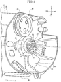
FIG. 3 is a perspective view showing a side wall part of a container body and its periphery in the toner container according to the embodiment of the present disclosure. -
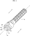
FIG. 4 is a perspective view showing a ratchet shaft in the toner container according to the embodiment of the present disclosure. -
FIG. 5 is a perspective view showing the toner container, in a state that a transmitting coupling and a following coupling are connected, according to the embodiment of the present disclosure. -
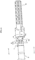
FIG. 6 is a perspective view showing the toner container, in a state that connection of the transmitting coupling and the following coupling is released, according to the embodiment of the present disclosure. - First, the entire structure of an
image forming apparatus 1 according to an embodiment of the present disclosure will be described. - Hereinafter, it will be described so that the front side of the
image forming apparatus 1 is positioned at a left side on a paper sheet ofFIG. 1 . Arrows Fr, Rr, L, R, U and Lo in each of the drawings respectively indicate a front side, a rear side, a left side, a right side, an upper side and a lower side of theprinter 1. - With reference to
FIG. 1 , theimage forming apparatus 1 is, for example, a printer. Theimage forming apparatus 1 includes a box-shaped apparatus body 2. In a lower part of theapparatus body 2, asheet feeding cartridge 3 storing sheets S (an example of a recording medium) is installed. In a top face of theapparatus body 2, an ejectedsheet tray 4 is provided. In an upper part of theapparatus body 2, anexposure device 5 is installed below the ejectedsheet tray 4. In an upper part of theapparatus body 2, a toner container 6 (an example of a toner containing case) is installed in front of theexposure device 5. - Inside the
apparatus body 2, a conveying path P for the sheet S is arranged. At an upstream end of the conveying path P, asheet feeding part 11 is provided. At an intermediate stream part of the conveying path P, animage forming part 7 is provided. Theimage forming part 7 has aphotosensitive drum 8 and a developing device 10 (an example of an attached member). To the developingdevice 10, thetoner container 6 is detachably attached. At a downstream part of the conveying path P, afixing device 12 is provided. - Next, image forming operation of the
image forming apparatus 1 having such a configuration will be described. - First, by a laser light (refer to an arrow of a broken line in
FIG. 1 ) from theexposure device 5, an electrostatic latent image is formed on thephotosensitive drum 8. Subsequently, the electrostatic latent image on thephotosensitive drum 8 is developed by thedevelopment device 10, and then, a toner image is formed. Thereby, the image forming operation is completed. - On the other hand, the sheet picked up from the
sheet feeding cartridge 3 by thesheet feeding part 11 is conveyed to theimage forming part 7 in a timing synchronized with the above-described image forming operation. In theimage forming part 7, the above-described toner image is transferred from thephotosensitive drum 6 to the sheet S. The sheet S with the transferred toner image is conveyed to a downstream side on the conveying path P to enter thefixing device 12 and, in thefixing device 12, the toner image is fixed on the sheet S. The sheet S with the fixed toner image is ejected from a downstream end of the conveying path P to the sheet ejectedtray 4. - Next, the
toner container 6 will be further described. - An arrow I accordingly shown in
FIG. 2 and later indicates an inward side in left and right directions of the toner container 6 (a side approaching the center in the left and right directions of the toner container 6), and an arrow O accordingly shown inFIG. 2 and later indicates an outward side in the left and right directions of the toner container 6 (a side separating from the center in the left and right directions of the toner container 6). An arrow R1 accordingly shown inFIG. 3 and later indicates a first rotating direction (hereinafter, called as a "first rotating direction R1"), and an arrow R2 accordingly shown inFIG. 3 and later indicates a second rotating direction opposite to the first rotating direction R1 (hereinafter, called as a "second rotating direction R2"). - With reference to
FIG. 2 , for thetoner container 6, a rotation axis X extended in the left and right directions (an example of one direction) is set. Hereinafter, a simply described "radial direction" indicates a radial direction of a circle around the rotation axis X, and a simply described "circumference direction" indicates a circumference direction around the rotation axis X. - The
toner container 6 includes acontainer body 21, a rotatingmember 22 arranged at the center of thecontainer body 21, a movingmember 23 attached on an outer circumference of the rotatingmember 22, anagitating member 24 attached to a right end of thecontainer body 21, a transmittingmember 25 and a connectingmember 26 located at a right side (an outward side in the left and right directions) of thecontainer body 21, and acover 27 covering the transmittingmember 25 and the connectingmember 26. Hereinafter, the above-described components of thetoner container 6 will be described in order. - With reference to
FIG. 2 , thecontainer body 21 of thetoner container 6 is formed in a box shape long in left and right directions. Inside thecontainer body 21, a first space S1 and a second space S2 are formed. In the first space S1, the toner is contained but, in the second space S2, no toner is contained. The second space S2 is arranged at a left side of the first space S1. - The
container body 21 includes aperipheral wall part 31, alid part 32 arranged at a left side of theperipheral wall part 31, and aside wall part 33 arranged at a right side of theperipheral wall part 31. - The
peripheral wall part 31 of thecontainer body 21 is formed in a cylindrical shape and is extended in the left and right directions. In a left end of theperipheral wall part 31, anopening part 35 is provided. On an outer circumference face of the left end of theperipheral wall part 31, anannular flange part 36 is protruded around the openingpart 35. In a right end of theperipheral wall part 31, a dischargingport 37 discharging the toner is provided. The dischargingport 37 is covered by an openable/closable shutter 38 (refer toFIG. 3 ). - With reference to
FIG. 2 , thelid part 32 of thecontainer body 21 is arranged along a flat face orthogonal to the rotation axis X. Thelid part 32 is formed separately from theperipheral wall part 31. An outer circumference portion of thelid part 32 is fixed to theflange part 36 of theperipheral wall part 31. Thelid part 32 closes theopening part 35 of theperipheral wall part 31. In the center of aleft face 32a (an outer face) of thelid part 32, a left side protrudedportion 40 is protruded. In the center of aright face 32b (an inner face) of thelid part 32, a supportingwall 43 is protruded at the back side of the left side protrudedportion 40. The supportingwall 43 is formed in an annular shape around the rotation axis X. - With reference with
FIGS. 2 and3 , theside wall part 33 of thecontainer body 21 is provided along a flat face orthogonal to the rotation axis X. Theside wall part 33 is made integrally with theperipheral wall part 31 and covers a right side (an outward side in the left and right directions) of theperipheral wall part 31. In the center of aright face 33a (an outer face) of theside wall part 33, a bearingportion 45 is protruded. The bearingportion 45 is formed in a cylindrical shape around the rotation axis X. In an upper part of theright face 33a of theside wall part 33, atoner filling port 46 is protruded above the bearingportion 45, and the toner is filled in the first space S1 of thecontainer body 21 via thistoner filling port 46. Thetoner filling port 46 is closed by acap 47. - With reference to
FIG. 2 , the rotatingmember 22 of thecontainer body 21 is configured to rotate around the rotation axis X. A part other than a right end (one end in the left and right directions) of the rotatingmember 22 is installed in thecontainer body 21. - The rotating
member 22 is extended in the left and right directions. In a left end (the other end in the left and right directions) of the rotatingmember 22, ajoint part 54 is provided. Thejoint part 54 is inserted into the supportingwall 43 arranged in theright face 32b of thelid part 32, and is rotatably supported by the supportingwall 43. On an outer circumference face at the center in the left and right directions of the rotatingmember 22, ascrew part 55 is provided. A right side portion of the rotatingmember 22 is inserted into the bearingportion 45 arranged in theside wall part 33 of thecontainer body 21. - With reference to
FIGS. 2 and3 , in the right end (one end in the left and right directions) of the rotatingmember 22, a followingcoupling 56 is provided. The followingcoupling 56 faces to the outside of thecontainer body 21. The followingcoupling 56 is formed so as to be along the circumference direction. In the followingcoupling 56, a pair offitting gaps 57 are provided. The pair offitting gaps 57 are arranged at opposite side to each other across the rotation axis X. At one end in the circumference direction (a downstream side end in the first rotating direction R1) of eachfitting gap 57, a first followingface 57a is formed. The first followingface 57a is extended in the left and right directions. At the other end in the circumference direction (an upstream side end in the first rotating direction R1) of eachfitting gap 57, a second followingface 57b is formed. The second followingface 57b is inclined relative to the left and right directions. - At the center in the radial direction of the right end of the rotating
member 22, ahole part 58 having a square shaped (non-circular shaped) section is provided. Thehole part 58 is located at a left side (an inward side in the left and right directions) from the followingcoupling 56. - With reference to
FIG. 2 , the movingmember 23 of thetoner container 6 partitions a space inside thecontainer body 21 into the first space S1 and the second space S2 in the left and right directions. The movingmember 23 is provided so as to be linearly movable in the left and right directions in a state that rotation of the movingmember 23 is restricted. - The moving
member 23 includes a seal piece 71, a pair of left and right sandwichingpieces 72 sandwiching the seal piece 71, and an engagingpiece 73 located at a left side of theleft sandwiching piece 72. An outer circumference face of the seal piece 71 is in contact with an inner circumference face of theperipheral wall part 31 of thecontainer body 21. On an inner circumference face of the engagingpiece 73, ascrew groove 76 is provided. Thescrew groove 76 is engaged with thescrew part 55 provided on the rotatingmember 22. Thereby, rotation of the rotatingmember 22 can be converted to linear movement of the movingmember 23 so as to be linearly movable in the left and right directions. - With reference to
FIG. 2 , the agitatingmember 24 of thetoner container 6 is relative-rotatably attached to the outer circumference of the rotatingmember 22. The agitatingmember 24 is configured to rotate around the rotation axis X. The agitatingmember 24 includes a holdingpiece 81, and afilm 82 held by the holdingpiece 81. - In the holding
piece 81 of the agitatingmember 24, the right side portion of the rotatingmember 22 is inserted. Thereby, the holdingpiece 81 supports the right side portion of the rotatingmember 22 rotatably. A left side portion of the holdingpiece 81 is installed in a right end of the first space S1 of thecontainer body 21. - A right side portion of the holding
piece 81 of the agitatingmember 24 is formed in a cylindrical shape around the rotation axis X. The right side portion of the holdingpiece 81 is inserted into the bearingportion 45 provided in theside wall part 33 of thecontainer body 21. Thereby, the agitatingmember 24 is rotatably supported by theside wall part 33 of thecontainer body 21. - With reference to
FIGS. 2 and3 , in a right end of the holdingpiece 81 of the agitatingmember 24, an agitatingcoupling 86 is provided. The agitatingcoupling 86 faces to the outside of thecontainer body 21. The agitatingcoupling 86 is formed so as to be along the circumference direction. The agitatingcoupling 86 is arranged outside an outer circumference of the followingcoupling 56. A maximum protrusion width in the left and right directions of the agitatingcoupling 86 relative to theright face 33a of theside wall part 33 of thecontainer body 21 is larger than a maximum protrusion width in the left and right directions of the followingcoupling 56 relative to theright face 33a of theside wall part 33 of thecontainer body 21. In the agitatingcoupling 86, a pair of recessedparts 87 are provided. The pair of recessedparts 87 are arranged at opposite side to each other across the rotation axis X. - With reference to
FIG. 2 , thefilm 82 of the agitatingmember 24 is installed in the right end of the first space S1 of thecontainer body 21. Thefilm 82 is made of, for example, a resin film, such as a PET film (Polyethylene Terephthalate Film), and has flexibility. A position in the left and right directions of thefilm 82 is overlapped with a position in the left and right directions of the dischargingport 37 provided in theperipheral wall part 31 of thecontainer body 21. - With reference to
FIG. 2 , the whole of the transmittingmember 25 of thetoner container 6 is arranged outside thecontainer body 21. The transmittingmember 25 includes a transmittingpiece 91, and aratchet mechanism 92 connecting the transmittingpiece 91 and the rotatingmember 22. - A left side portion of the transmitting
piece 91 of the transmittingmember 25 is formed in a cylindrical shape around the rotation axis X. A right side portion of the transmittingpiece 91 is formed in an annular shape around the rotation axis X. On an outer circumference portion of the right side portion of the transmittingpiece 91, a transmittinggear 93 is provided. The transmittinggear 93 is connected to afirst driving gear 95 of a first drivingmember 94 provided in the developingdevice 10. - The
ratchet mechanism 92 of the transmittingmember 25 includes aratchet shaft 96, and a ratchet piece 97 provided on an outer circumference of theratchet shaft 96. - The
ratchet shaft 96 of theratchet mechanism 92 of the transmittingmember 25 is extended in the left and right directions. In a left end of theratchet shaft 96, a transmittingcoupling 98 is provided. The transmittingcoupling 98 is connected to the followingcoupling 56 provided in the rotatingmember 22. Thereby, the transmittingmember 25 is linearly connected to the rotatingmember 22, and the transmittingmember 25 and the rotatingmember 22 are integrally rotated around the rotation axis X. The transmittingcoupling 98 together with the followingcoupling 56 composes a restrictingmechanism 99. The restrictingmechanism 99 is arranged in an engaging part E of the rotatingmember 22 and the transmittingmember 25. - With reference to
FIG. 4 , in an outer circumference face of the transmittingcoupling 98, a pair offitting protrusions 100 are provided. The pair offitting protrusions 100 are arranged at opposite side to each other across the rotation axis X. At one end in the circumference direction (a downstream side end in the first rotating direction R1) of eachfitting protrusion 100, afirst transmitting face 100a is formed. Thefirst transmitting face 100a is extended in the left and right directions. At the other end in the circumference direction (an upstream side end in the first rotating direction R1) of eachfitting protrusion 100, asecond transmitting face 100b is formed. Thesecond transmitting face 100b is inclined relative to the left and right directions. - With reference to
FIG. 2 , the ratchet piece 97 of theratchet mechanism 92 of the transmittingmember 25 is formed in a cylindrical shape around the rotation axis X. The ratchet piece 97 is arranged between the transmittingpiece 91 and theratchet shaft 96. - With reference to
FIG. 2 , the whole of the connectingmember 26 of thetoner container 6 is arranged outside thecontainer body 21. The connectingmember 26 includes acylindrical part 101, and anannular part 102 protruded from an outer circumference face of a right side portion of thecylindrical part 101. - The
cylindrical part 101 of the connectingmember 26 is formed in a cylindrical shape around the rotation axis X. In a left end of thecylindrical part 101, a connectingcoupling 104 is provided. The connectingcoupling 104 is connected to the agitatingcoupling 86 provided in the holdingpiece 81 of the agitatingmember 24. Thereby, the connectingmember 26 is linearly connected to the agitatingmember 24, and the connectingmember 26 and the agitatingmember 24 are integrally rotated around the rotation axis X. In the connectingcoupling 104, a pair of protruded parts (not shown) are provided. Each protruded part is fitted into each recessedpart 87 of the agitatingcoupling 86. - The
annular part 102 of the connectingmember 26 is formed in an annular shape around the rotation axis X. On an outer circumference face of theannular part 102, a connectinggear 106 is provided. The connectinggear 106 is connected to asecond driving gear 108 of asecond driving member 107 provided in the developingdevice 10. - With reference to
FIG. 2 , thecover 27 of thetoner container 6 is attached to the right end of thecontainer body 21. Thecover 27 covers a right side (an outward side in the left and right directions) of theside wall part 33 of thecontainer body 21. Thecover 27 covers the followingcoupling 56 and the agitatingcoupling 86. - On a right face (an outer face) of the
cover 27, a right side protrudedportion 111 is protruded. On a left face (an inner face) of thecover 27, a bearingportion 112 is provided at a back side of the right side protrudedportion 111. The bearingportion 112 is formed in a cylindrical shape around the rotation axis X. The bearingportion 112 supports a right end of theratchet shaft 96 of theratchet mechanism 92 rotatably. In a lower part of thecover 27, awindow portion 113 is provided, and parts of the transmittinggear 93 and the connectinggear 106 are exposed to the outside of thetoner container 6 via thewindow portion 113. - Next, operation replenishing the toner from the
toner container 6 to the developing device 10 (hereinafter, called as "toner replenishing operation") will be described. - When the toner replenishing operation is executed, a drive source (not shown) rotates the
second driving member 107. When thesecond driving member 107 is thus rotated, this rotation is transmitted to the agitatingmember 24 by the connectingmember 26 to rotate the agitatingmember 24. Thereby, thefilm 82 of the agitatingmember 24 agitates the toner contained in the first space S1 of thecontainer body 21 and conveys this toner to the dischargingport 37. The toner thus conveyed to the dischargingport 37 is discharged to the outside of thecontainer body 21 via the dischargingport 37 and is replenished to the developingdevice 10. Thereby, the toner replenishing operation is completed. - After the toner replenishing operation as described above is executed, the toner near the discharging
port 37 in the first space S1 of thecontainer body 21 is decreased. According to this, if a toner sensor (not shown) senses that the toner near the dischargingport 37 becomes less than a predetermined threshold value, a drive source (not shown) rotates the first drivingmember 94. When the first drivingmember 94 is thus rotated, this rotation is transmitted to the rotatingmember 22 by the transmittingmember 25 to rotate the rotatingmember 22 in the first rotating direction R1. When the rotatingmember 22 is thus rotated in the first rotating direction R1, the movingmember 23 attached on the outer circumference of the rotatingmember 22 is moved to the right side in the left and right directions (a side approaching the discharging port 37), as indicated by an arrow A inFIG. 2 . According to this, a toner quantity in the first space S1 of thecontainer body 21 is decreased, and then, the toner in the first space S1 of thecontainer body 21 is pushed by the movingmember 23 and moved to the right side (the side approaching the discharging port 37). That is, the movingmember 23 conveys the toner in thecontainer body 21 to the dischargingport 37. Therefore, the toner is filled up in a space near the dischargingport 37 again, and then, it is possible to replenish a sufficient quantity of the toner from thetoner container 6 to the developingdevice 10 in next toner replenishing operation. - Incidentally, in the
toner container 6 configured as described above, if a user operates the followingcoupling 56 by mistake to rotate the rotatingmember 22 in the second rotating direction R2, the movingmember 23 may be moved to the left side (a side separating from the discharging port 37). If such situation is caused, it is feared that distribution of the toner in thecontainer body 21 is varied, a stable quantity of the toner cannot be discharged from the dischargingport 37, and toner replenishment from thetoner container 6 to the developingdevice 10 becomes unstable. - However, in the present embodiment, the agitating
coupling 86 is arranged outside the outer circumference of the followingcoupling 56. By applying such a configuration, it is possible to restrict the user from operating the followingcoupling 56 by mistake, and to certainly restrict rotation of the rotatingmember 22 in the second rotating direction R2. Moreover, even if thecover 27 is detached from thecontainer body 21, it is possible to protect the followingcoupling 56 by the agitatingcoupling 86 against impact from the outside. - In addition, in the present embodiment, when the toner replenishing operation is executed, if the transmitting
piece 91 of the transmittingmember 25 is rotated in the first rotating direction R1, the ratchet piece 97 and theratchet shaft 96 of theratchet mechanism 92 of the transmittingmember 25 is rotated in the first rotating direction R1 together with the transmittingpiece 91. Therefore, the rotatingmember 22 connected to theratchet shaft 96 is rotated in the first rotating direction R1 together with theratchet shaft 96 in a body. Thus, rotation of the transmittingpiece 91 is transmitted to the rotatingmember 22 by theratchet mechanism 92 to rotate the rotatingmember 22 in the first rotating direction R1. - On the other hand, if the user rotates the transmitting
piece 91 of the transmittingmember 25 in the second rotating direction R2, the ratchet piece 97 of theratchet mechanism 92 of the transmittingmember 25 is rotated in the second rotating direction R2 together with the transmittingpiece 91, but theratchet shaft 96 of theratchet mechanism 92 of the transmittingmember 25 is not rotated. That is, the ratchet piece 97 is raced with respect to theratchet shaft 96. Therefore, the rotatingmember 22 connected to theratchet shaft 96 is not rotated. Thus, by theratchet mechanism 92, transmission of rotation from the transmittingpiece 91 to the rotatingmember 22 is intercepted, and then, rotation of the rotatingmember 22 in the second rotating direction R2 is restricted. - As described above, in the present embodiment, rotation of the rotating
member 22 in the second rotating direction R2 is restricted by theratchet mechanism 92. However, in a case where the user detaches thecover 27 from thecontainer body 21 and operates theratchet shaft 96 by mistake to rotate theratchet shaft 96 in the second rotating direction R2, because theratchet mechanism 92 does not work, it is feared that rotation of the rotatingmember 22 in the second rotating direction R2 cannot be restricted. That is, it is feared that only theratchet mechanism 92 cannot certainly restrict rotation of the rotatingmember 22 in the second rotating direction R2. Thereupon, in the present embodiment, the rotatingmember 22 is certainly restricted from rotating in the second rotating direction R2, as follows. - With reference to
FIG. 5 , when the toner replenishing operation is executed, in a case where theratchet shaft 96 is rotated in the first rotating direction R1, in a state that eachfitting protrusion 100 of the transmittingcoupling 98 and eachfitting gap 57 of the followingcoupling 56 are fitted, thefirst transmitting face 100a of eachfitting protrusion 100 pushes the first followingface 57a of eachfitting gap 57. When thefirst transmitting face 100a thus pushes the first followingface 57a, since thefirst transmitting face 100a and the first followingface 57a are extended in the left and right directions, rotation of theratchet shaft 96 is transmitted to the rotatingmember 22, and the rotatingmember 22 is rotated in the first rotating direction R1 together with theratchet shaft 96 in a body. That is, by the restrictingmechanism 99 composed of the followingcoupling 56 and the transmittingcoupling 98, rotation of the rotatingmember 22 in the first rotating direction R1 is allowed. - On the other hand, with reference to
FIG. 6 , in a case where the user makes theratchet shaft 96 rotate in the second rotating direction R2, thesecond transmitting face 100b of eachfitting protrusion 100 pushes the second followingface 57b of eachfitting gap 57. Even if thesecond transmitting face 100b thus pushes the second followingface 57b, since thesecond transmitting face 100b and the second followingface 57b are inclined relative to the left and right directions, rotation of theratchet shaft 96 cannot be transmitted to the rotatingmember 22. Therefore, theratchet shaft 96 is moved to a right side (an outward side in the left and right directions) with respect to the rotatingmember 22, fitting of eachfitting protrusion 100 of the transmittingcoupling 98 and eachfitting gap 57 of the followingcoupling 56 is released, and theratchet shaft 96 is raced with respect to the rotatingmember 22. That is, by the restrictingmechanism 99 composed of the followingcoupling 56 and the transmittingcoupling 98, rotation of the rotatingmember 22 in the second rotating direction R2 is restricted. - In the present embodiment, the restricting
mechanism 99 for allowing rotation of the rotatingmember 22 in the first rotating direction R1 and restricting rotation of the rotatingmember 22 in the second rotating direction R2 opposite to the first rotating direction R1 is provided in the engaging part E of the rotatingmember 22 and the transmittingmember 25. By applying such a configuration, in a case where the user operates theratchet shaft 96 by mistake to rotate theratchet shaft 96 in the second rotating direction R2, it is possible to certainly restrict rotation of the rotatingmember 22 in the second rotating direction R2. - In addition, the restricting
mechanism 99 is composed of the followingcoupling 56 and the transmittingcoupling 98. By applying such a configuration, it is possible to achieve assembly of the restrictingmechanism 99 only by connecting the followingcoupling 56 and the transmittingcoupling 98. Therefore, it is facilitate assembly of the restrictingmechanism 99. - Moreover, when the
ratchet shaft 96 is rotated in the first rotating direction R1, thefirst transmitting face 100a pushes the first followingface 57a, and then, the rotatingmember 22 is rotated in the first rotating direction R1 together with theratchet shaft 96 in a body. On the other hand, when theratchet shaft 96 is rotated in the second rotating direction R2, thesecond transmitting face 100b pushes the second followingface 57b, and then, theratchet shaft 96 is raced with respect to the rotatingmember 22. By applying such a configuration, it is possible to allow rotation of the rotatingmember 22 in the first rotating direction R1 and simultaneously to certainly restrict rotation of the rotatingmember 22 in the second rotating direction R2 by using a simple configuration. - Further, the maximum protrusion width in the left and right directions of the agitating
coupling 86 relative to theright face 33a of theside wall part 33 of thecontainer body 21 is larger than the maximum protrusion width in the left and right directions of the followingcoupling 56 relative to theright face 33a of theside wall part 33 of thecontainer body 21. By applying such a configuration, it is possible to more effectively restrict the user from operating the followingcoupling 56 by mistake, and to more certainly restrict rotation of the rotatingmember 22 in the second rotating direction R2. Moreover, even if thecover 27 is detached from thecontainer body 21, it is possible to more effectively protect the followingcoupling 56 by the agitatingcoupling 86 against impact from the outside. - Furthermore, the following
coupling 56 and the transmittingcoupling 98 are covered by thecover 27. By applying such a configuration, since it is possible to restrict the followingcoupling 56 and the transmittingcoupling 98 from being broken by impact from the outside, it is possible to certainly work the followingcoupling 56 and the transmittingcoupling 98. - Moreover, the
ratchet mechanism 92 transmits rotation of the transmittingpiece 91 to the rotatingmember 22 in a case where the transmittingpiece 91 is rotated in the first rotating direction R1, and intercepts transmission of rotation of the transmittingpiece 91 to the rotatingmember 22 in a case where the transmittingpiece 91 is rotated in the second rotating direction R2. By applying such a configuration, it is possible to more certainly restrict rotation of the rotatingmember 22 in the second rotating direction R2. - Further, the
image forming apparatus 1 includes the above-describedtoner container 6, the developingdevice 10 to which thetoner container 6 is detachably attached. By applying such a configuration, it is possible to provide theimage forming apparatus 1 including thetoner container 6 being capable of certainly restricting rotation of the rotatingmember 22 in the second rotating direction R2. - In the present embodiment, a part (a part other than the right end) of the rotating
member 22 is installed in thecontainer body 21. However, in another embodiment, the whole of the rotatingmember 22 may be installed in thecontainer body 21. - In the present embodiment, the whole of the transmitting
member 25 is arranged outside thecontainer body 21. However, in another embodiment, a part of the transmittingmember 25 may be arranged outside thecontainer body 21. - In the present embodiment, the
toner container 6 is detachably attached to the developingdevice 10. However, in another embodiment, thetoner container 6 may be detachably attached to a member other than the developing device 10 (e.g. the apparatus body 2). - In the present embodiment, the
image forming apparatus 1 is the printer. However, in another embodiment, theimage forming apparatus 1 may be a copying machine, a facsimile, a multifunction peripheral (an image forming apparatus compositely including a print function, a copy function, a facsimile function and others) or the like. - The above-description of the embodiment of the present disclosure was described about a preferable embodiment of the toner container and the image forming apparatus according to the disclosure. However, the technical scope of the present disclosure is not limited to the embodiments.
Claims (8)
- A toner container (6) comprising:a container body (21) having a discharging port (37) discharging a toner and containing the toner;a rotating member (22) rotated around a rotation axis (X) extended in one direction, wherein at least a part of the rotating member (22) being installed in the container body (21);a moving member (23) attached to the rotating member (22), moved in the one direction in accordance with rotation of the rotating member (22), and conveying the toner in the container body (21) to the discharging port (37);a transmitting member (25) connected to the rotating member (22), and transmitting rotation to the rotating member (22), wherein at least a part of the transmitting member (25) being arranged outside the container body (21);an agitating member (24) rotated around the rotation axis (X), and agitating the toner contained in the container body (21); anda connecting member (26) connected to the agitating member (24), and transmitting rotation to the agitating member (24),wherein the rotating member (22) includes a following coupling (56) facing to the outside of the container body (21),the transmitting member (25) includes a transmitting coupling (98) connected to the following coupling (56),the agitating member (24) includes an agitating coupling (86) facing to the outside of the container body (21),the connecting member (26) includes a connecting coupling (104) connected to the agitating coupling (86),the agitating coupling (86) is arranged outside the outer circumference of the following coupling (56).
- The toner container (6) according to claim 1, wherein
in an engaging part of the rotating member (22) and the transmitting member (25), a restricting mechanism (99) for allowing rotation of the rotating member (22) in a first rotating direction (R1) and restricting rotation of the rotating member (22) in a second rotating direction (R2) opposite to the first rotating direction (R1) is provided,
the restricting mechanism (99) is composed of the following coupling (56) and the transmitting coupling (98). - The toner container (6) according to claim 2, wherein
the following coupling (56) includes:a first following face (57a) extended in the one direction; anda second following face (57b) inclined relative to the one direction,the transmitting coupling (98) includes:a first transmitting face (100a) extended in the one direction; anda second transmitting face (100b) inclined relative to the one direction,when the transmitting member (25) is rotated in the first rotating direction (R1), the first transmitting face (100a) pushes the first following face (57a), and then, the rotating member (22) is rotated in the first rotating direction (R1) together with the transmitting member (25) in a body,when the transmitting member (25) is rotated in the second rotating direction (R2), the second transmitting face (100b) pushes the second following face (57b), and then, the transmitting member (25) is raced with respect to the rotating member (22). - The toner container (6) according to any one of claims 1-3, wherein
a maximum protrusion width in the one direction of the agitating coupling (86) relative to an outer face (33a) of the container body (21) is larger than a maximum protrusion width in the one direction of the following coupling (56) relative to the outer face (33a) of the container body (21). - The toner container (6) according to any one of claims 1-4 further comprising:a cover (27) attached to the container body (21),wherein the following coupling (56) and the agitating coupling (86) are covered by the cover (27).
- The toner container (6) according to any one of claims 1-5, wherein
the transmitting member (25) includes:a transmitting piece (91) on which a transmitting gear (93) is provided; anda ratchet mechanism (92) connecting the transmitting piece (91) and the rotating member (22),the ratchet mechanism (92) transmits rotation of the transmitting piece (91) to the rotating member (22) in a case where the transmitting piece (91) is rotated in the first rotating direction (R1), and intercepts transmission of rotation of the transmitting piece (91) to the rotating member (22) in a case where the transmitting piece (91) is rotated in a second rotating direction (R2) opposite to the first rotating direction (R1). - The toner container (6) according to any one of claims 1-6, wherein
the moving member (23) partitions a space inside the container body (21) into a first space (S1) at one end side in the one direction and a second space (S2) at the other end side in the one direction,
the discharging port (37) is provided at the one end side in the container body (21),
the moving member (23) is moved to the one end side in accordance with rotation of the rotating member (22) in a first rotating direction (R1). - An image forming apparatus (1) comprising:the toner container (6) according to any one of claims 1-7; andan attached member (10) to which the toner container (6) is detachably attached.
Applications Claiming Priority (1)
| Application Number | Priority Date | Filing Date | Title |
|---|---|---|---|
| JP2018159728A JP7143681B2 (en) | 2018-08-28 | 2018-08-28 | Toner container and image forming apparatus |
Publications (2)
| Publication Number | Publication Date |
|---|---|
| EP3617806A1 true EP3617806A1 (en) | 2020-03-04 |
| EP3617806B1 EP3617806B1 (en) | 2022-08-10 |
Family
ID=67734496
Family Applications (1)
| Application Number | Title | Priority Date | Filing Date |
|---|---|---|---|
| EP19193008.0A Active EP3617806B1 (en) | 2018-08-28 | 2019-08-22 | Toner container and image forming apparatus |
Country Status (4)
| Country | Link |
|---|---|
| US (1) | US10768549B2 (en) |
| EP (1) | EP3617806B1 (en) |
| JP (1) | JP7143681B2 (en) |
| CN (1) | CN110865524B (en) |
Citations (2)
| Publication number | Priority date | Publication date | Assignee | Title |
|---|---|---|---|---|
| EP2980652A1 (en) * | 2014-07-30 | 2016-02-03 | Kyocera Document Solutions Inc. | Developer container and image forming apparatus including the same |
| CN108323188A (en) * | 2017-07-07 | 2018-07-24 | 京瓷办公信息系统株式会社 | Developer container and the image forming apparatus for having the developer container |
Family Cites Families (11)
| Publication number | Priority date | Publication date | Assignee | Title |
|---|---|---|---|---|
| JP5377686B2 (en) * | 2012-01-31 | 2013-12-25 | 京セラドキュメントソリューションズ株式会社 | Image forming apparatus and toner container |
| US8923734B2 (en) * | 2012-09-14 | 2014-12-30 | Lexmark International, Inc. | Volumetric toner cartridge having removable exit paddle |
| JP5680612B2 (en) * | 2012-11-19 | 2015-03-04 | 京セラドキュメントソリューションズ株式会社 | Toner container and image forming apparatus |
| JP5919254B2 (en) | 2013-12-27 | 2016-05-18 | 京セラドキュメントソリューションズ株式会社 | Developer container and image forming apparatus provided with the same |
| JP6159675B2 (en) * | 2014-03-27 | 2017-07-05 | 京セラドキュメントソリューションズ株式会社 | Developer container and image forming apparatus including the same |
| JP6222009B2 (en) | 2014-08-27 | 2017-11-01 | 京セラドキュメントソリューションズ株式会社 | Image forming apparatus |
| JP6693402B2 (en) * | 2016-12-09 | 2020-05-13 | 京セラドキュメントソリューションズ株式会社 | Image forming apparatus and toner container |
| JP6638640B2 (en) * | 2016-12-22 | 2020-01-29 | 京セラドキュメントソリューションズ株式会社 | Toner container and image forming apparatus |
| CN108227436B (en) * | 2016-12-09 | 2021-08-13 | 京瓷办公信息系统株式会社 | Toner container and image forming apparatus |
| CN207571468U (en) * | 2017-12-26 | 2018-07-03 | 京瓷办公信息系统株式会社 | Toner container and image forming device |
| CN207601513U (en) * | 2017-12-26 | 2018-07-10 | 京瓷办公信息系统株式会社 | Toner container and image forming apparatus |
-
2018
- 2018-08-28 JP JP2018159728A patent/JP7143681B2/en active Active
-
2019
- 2019-08-22 EP EP19193008.0A patent/EP3617806B1/en active Active
- 2019-08-26 US US16/550,339 patent/US10768549B2/en active Active
- 2019-08-28 CN CN201910799780.3A patent/CN110865524B/en active Active
Patent Citations (2)
| Publication number | Priority date | Publication date | Assignee | Title |
|---|---|---|---|---|
| EP2980652A1 (en) * | 2014-07-30 | 2016-02-03 | Kyocera Document Solutions Inc. | Developer container and image forming apparatus including the same |
| CN108323188A (en) * | 2017-07-07 | 2018-07-24 | 京瓷办公信息系统株式会社 | Developer container and the image forming apparatus for having the developer container |
Also Published As
| Publication number | Publication date |
|---|---|
| US10768549B2 (en) | 2020-09-08 |
| US20200073283A1 (en) | 2020-03-05 |
| JP7143681B2 (en) | 2022-09-29 |
| CN110865524B (en) | 2022-06-28 |
| CN110865524A (en) | 2020-03-06 |
| EP3617806B1 (en) | 2022-08-10 |
| JP2020034661A (en) | 2020-03-05 |
Similar Documents
| Publication | Publication Date | Title |
|---|---|---|
| EP3287849B1 (en) | Toner case and image forming apparatus | |
| CN106371299A (en) | Toner container attachable to and detachable from image forming apparatus | |
| US9229369B2 (en) | Image forming apparatus | |
| EP3267260B1 (en) | Toner container and image formation device comprising same | |
| CN108227437B (en) | Toner container and image forming apparatus | |
| US10859947B2 (en) | Toner container having operation member for making shutter open or close and image forming apparatus | |
| EP3617806B1 (en) | Toner container and image forming apparatus | |
| EP3260922B1 (en) | Developer case and image forming apparatus including the same | |
| JP2018072682A (en) | Toner container and image forming apparatus | |
| US10838321B2 (en) | Toner container and image forming apparatus | |
| US10345740B1 (en) | Toner case and image forming apparatus | |
| JP6555207B2 (en) | Image forming apparatus and toner container mounted on image forming apparatus | |
| CN205982994U (en) | Toner container and image forming apparatus | |
| US11016414B2 (en) | Image forming apparatus | |
| US9753409B2 (en) | Toner case and image forming apparatus | |
| JP2020067533A (en) | Toner container, image forming apparatus, and method for assembling toner container | |
| CN107783394A (en) | Toner container and image processing system | |
| JP2018063360A (en) | Toner storage tool and image forming apparatus | |
| JP2017198921A (en) | Image formation device |
Legal Events
| Date | Code | Title | Description |
|---|---|---|---|
| PUAI | Public reference made under article 153(3) epc to a published international application that has entered the european phase |
Free format text: ORIGINAL CODE: 0009012 |
|
| STAA | Information on the status of an ep patent application or granted ep patent |
Free format text: STATUS: THE APPLICATION HAS BEEN PUBLISHED |
|
| AK | Designated contracting states |
Kind code of ref document: A1 Designated state(s): AL AT BE BG CH CY CZ DE DK EE ES FI FR GB GR HR HU IE IS IT LI LT LU LV MC MK MT NL NO PL PT RO RS SE SI SK SM TR |
|
| AX | Request for extension of the european patent |
Extension state: BA ME |
|
| STAA | Information on the status of an ep patent application or granted ep patent |
Free format text: STATUS: REQUEST FOR EXAMINATION WAS MADE |
|
| 17P | Request for examination filed |
Effective date: 20200831 |
|
| RBV | Designated contracting states (corrected) |
Designated state(s): AL AT BE BG CH CY CZ DE DK EE ES FI FR GB GR HR HU IE IS IT LI LT LU LV MC MK MT NL NO PL PT RO RS SE SI SK SM TR |
|
| GRAP | Despatch of communication of intention to grant a patent |
Free format text: ORIGINAL CODE: EPIDOSNIGR1 |
|
| STAA | Information on the status of an ep patent application or granted ep patent |
Free format text: STATUS: GRANT OF PATENT IS INTENDED |
|
| INTG | Intention to grant announced |
Effective date: 20220311 |
|
| GRAS | Grant fee paid |
Free format text: ORIGINAL CODE: EPIDOSNIGR3 |
|
| GRAA | (expected) grant |
Free format text: ORIGINAL CODE: 0009210 |
|
| STAA | Information on the status of an ep patent application or granted ep patent |
Free format text: STATUS: THE PATENT HAS BEEN GRANTED |
|
| AK | Designated contracting states |
Kind code of ref document: B1 Designated state(s): AL AT BE BG CH CY CZ DE DK EE ES FI FR GB GR HR HU IE IS IT LI LT LU LV MC MK MT NL NO PL PT RO RS SE SI SK SM TR |
|
| REG | Reference to a national code |
Ref country code: AT Ref legal event code: REF Ref document number: 1510997 Country of ref document: AT Kind code of ref document: T Effective date: 20220815 Ref country code: CH Ref legal event code: EP |
|
| REG | Reference to a national code |
Ref country code: DE Ref legal event code: R096 Ref document number: 602019018006 Country of ref document: DE |
|
| REG | Reference to a national code |
Ref country code: IE Ref legal event code: FG4D |
|
| REG | Reference to a national code |
Ref country code: NL Ref legal event code: MP Effective date: 20220810 |
|
| REG | Reference to a national code |
Ref country code: LT Ref legal event code: MG9D |
|
| PG25 | Lapsed in a contracting state [announced via postgrant information from national office to epo] |
Ref country code: SE Free format text: LAPSE BECAUSE OF FAILURE TO SUBMIT A TRANSLATION OF THE DESCRIPTION OR TO PAY THE FEE WITHIN THE PRESCRIBED TIME-LIMIT Effective date: 20220810 Ref country code: RS Free format text: LAPSE BECAUSE OF FAILURE TO SUBMIT A TRANSLATION OF THE DESCRIPTION OR TO PAY THE FEE WITHIN THE PRESCRIBED TIME-LIMIT Effective date: 20220810 Ref country code: PT Free format text: LAPSE BECAUSE OF FAILURE TO SUBMIT A TRANSLATION OF THE DESCRIPTION OR TO PAY THE FEE WITHIN THE PRESCRIBED TIME-LIMIT Effective date: 20221212 Ref country code: NO Free format text: LAPSE BECAUSE OF FAILURE TO SUBMIT A TRANSLATION OF THE DESCRIPTION OR TO PAY THE FEE WITHIN THE PRESCRIBED TIME-LIMIT Effective date: 20221110 Ref country code: NL Free format text: LAPSE BECAUSE OF FAILURE TO SUBMIT A TRANSLATION OF THE DESCRIPTION OR TO PAY THE FEE WITHIN THE PRESCRIBED TIME-LIMIT Effective date: 20220810 Ref country code: LV Free format text: LAPSE BECAUSE OF FAILURE TO SUBMIT A TRANSLATION OF THE DESCRIPTION OR TO PAY THE FEE WITHIN THE PRESCRIBED TIME-LIMIT Effective date: 20220810 Ref country code: LT Free format text: LAPSE BECAUSE OF FAILURE TO SUBMIT A TRANSLATION OF THE DESCRIPTION OR TO PAY THE FEE WITHIN THE PRESCRIBED TIME-LIMIT Effective date: 20220810 Ref country code: FI Free format text: LAPSE BECAUSE OF FAILURE TO SUBMIT A TRANSLATION OF THE DESCRIPTION OR TO PAY THE FEE WITHIN THE PRESCRIBED TIME-LIMIT Effective date: 20220810 |
|
| REG | Reference to a national code |
Ref country code: AT Ref legal event code: MK05 Ref document number: 1510997 Country of ref document: AT Kind code of ref document: T Effective date: 20220810 |
|
| PG25 | Lapsed in a contracting state [announced via postgrant information from national office to epo] |
Ref country code: PL Free format text: LAPSE BECAUSE OF FAILURE TO SUBMIT A TRANSLATION OF THE DESCRIPTION OR TO PAY THE FEE WITHIN THE PRESCRIBED TIME-LIMIT Effective date: 20220810 Ref country code: IS Free format text: LAPSE BECAUSE OF FAILURE TO SUBMIT A TRANSLATION OF THE DESCRIPTION OR TO PAY THE FEE WITHIN THE PRESCRIBED TIME-LIMIT Effective date: 20221210 Ref country code: HR Free format text: LAPSE BECAUSE OF FAILURE TO SUBMIT A TRANSLATION OF THE DESCRIPTION OR TO PAY THE FEE WITHIN THE PRESCRIBED TIME-LIMIT Effective date: 20220810 Ref country code: GR Free format text: LAPSE BECAUSE OF FAILURE TO SUBMIT A TRANSLATION OF THE DESCRIPTION OR TO PAY THE FEE WITHIN THE PRESCRIBED TIME-LIMIT Effective date: 20221111 |
|
| REG | Reference to a national code |
Ref country code: CH Ref legal event code: PL |
|
| PG25 | Lapsed in a contracting state [announced via postgrant information from national office to epo] |
Ref country code: SM Free format text: LAPSE BECAUSE OF FAILURE TO SUBMIT A TRANSLATION OF THE DESCRIPTION OR TO PAY THE FEE WITHIN THE PRESCRIBED TIME-LIMIT Effective date: 20220810 Ref country code: RO Free format text: LAPSE BECAUSE OF FAILURE TO SUBMIT A TRANSLATION OF THE DESCRIPTION OR TO PAY THE FEE WITHIN THE PRESCRIBED TIME-LIMIT Effective date: 20220810 Ref country code: LU Free format text: LAPSE BECAUSE OF NON-PAYMENT OF DUE FEES Effective date: 20220822 Ref country code: LI Free format text: LAPSE BECAUSE OF NON-PAYMENT OF DUE FEES Effective date: 20220831 Ref country code: ES Free format text: LAPSE BECAUSE OF FAILURE TO SUBMIT A TRANSLATION OF THE DESCRIPTION OR TO PAY THE FEE WITHIN THE PRESCRIBED TIME-LIMIT Effective date: 20220810 Ref country code: DK Free format text: LAPSE BECAUSE OF FAILURE TO SUBMIT A TRANSLATION OF THE DESCRIPTION OR TO PAY THE FEE WITHIN THE PRESCRIBED TIME-LIMIT Effective date: 20220810 Ref country code: CZ Free format text: LAPSE BECAUSE OF FAILURE TO SUBMIT A TRANSLATION OF THE DESCRIPTION OR TO PAY THE FEE WITHIN THE PRESCRIBED TIME-LIMIT Effective date: 20220810 Ref country code: CH Free format text: LAPSE BECAUSE OF NON-PAYMENT OF DUE FEES Effective date: 20220831 Ref country code: AT Free format text: LAPSE BECAUSE OF FAILURE TO SUBMIT A TRANSLATION OF THE DESCRIPTION OR TO PAY THE FEE WITHIN THE PRESCRIBED TIME-LIMIT Effective date: 20220810 |
|
| REG | Reference to a national code |
Ref country code: BE Ref legal event code: MM Effective date: 20220831 |
|
| REG | Reference to a national code |
Ref country code: DE Ref legal event code: R097 Ref document number: 602019018006 Country of ref document: DE |
|
| PG25 | Lapsed in a contracting state [announced via postgrant information from national office to epo] |
Ref country code: SK Free format text: LAPSE BECAUSE OF FAILURE TO SUBMIT A TRANSLATION OF THE DESCRIPTION OR TO PAY THE FEE WITHIN THE PRESCRIBED TIME-LIMIT Effective date: 20220810 Ref country code: MC Free format text: LAPSE BECAUSE OF FAILURE TO SUBMIT A TRANSLATION OF THE DESCRIPTION OR TO PAY THE FEE WITHIN THE PRESCRIBED TIME-LIMIT Effective date: 20220810 Ref country code: EE Free format text: LAPSE BECAUSE OF FAILURE TO SUBMIT A TRANSLATION OF THE DESCRIPTION OR TO PAY THE FEE WITHIN THE PRESCRIBED TIME-LIMIT Effective date: 20220810 |
|
| P01 | Opt-out of the competence of the unified patent court (upc) registered |
Effective date: 20230420 |
|
| PLBE | No opposition filed within time limit |
Free format text: ORIGINAL CODE: 0009261 |
|
| STAA | Information on the status of an ep patent application or granted ep patent |
Free format text: STATUS: NO OPPOSITION FILED WITHIN TIME LIMIT |
|
| PG25 | Lapsed in a contracting state [announced via postgrant information from national office to epo] |
Ref country code: AL Free format text: LAPSE BECAUSE OF FAILURE TO SUBMIT A TRANSLATION OF THE DESCRIPTION OR TO PAY THE FEE WITHIN THE PRESCRIBED TIME-LIMIT Effective date: 20220810 |
|
| 26N | No opposition filed |
Effective date: 20230511 |
|
| PG25 | Lapsed in a contracting state [announced via postgrant information from national office to epo] |
Ref country code: IE Free format text: LAPSE BECAUSE OF NON-PAYMENT OF DUE FEES Effective date: 20220822 |
|
| PG25 | Lapsed in a contracting state [announced via postgrant information from national office to epo] |
Ref country code: SI Free format text: LAPSE BECAUSE OF FAILURE TO SUBMIT A TRANSLATION OF THE DESCRIPTION OR TO PAY THE FEE WITHIN THE PRESCRIBED TIME-LIMIT Effective date: 20220810 |
|
| PG25 | Lapsed in a contracting state [announced via postgrant information from national office to epo] |
Ref country code: BE Free format text: LAPSE BECAUSE OF NON-PAYMENT OF DUE FEES Effective date: 20220831 |
|
| PG25 | Lapsed in a contracting state [announced via postgrant information from national office to epo] |
Ref country code: HU Free format text: LAPSE BECAUSE OF FAILURE TO SUBMIT A TRANSLATION OF THE DESCRIPTION OR TO PAY THE FEE WITHIN THE PRESCRIBED TIME-LIMIT; INVALID AB INITIO Effective date: 20190822 |
|
| PG25 | Lapsed in a contracting state [announced via postgrant information from national office to epo] |
Ref country code: CY Free format text: LAPSE BECAUSE OF FAILURE TO SUBMIT A TRANSLATION OF THE DESCRIPTION OR TO PAY THE FEE WITHIN THE PRESCRIBED TIME-LIMIT Effective date: 20220810 |
|
| PG25 | Lapsed in a contracting state [announced via postgrant information from national office to epo] |
Ref country code: MK Free format text: LAPSE BECAUSE OF FAILURE TO SUBMIT A TRANSLATION OF THE DESCRIPTION OR TO PAY THE FEE WITHIN THE PRESCRIBED TIME-LIMIT Effective date: 20220810 Ref country code: IT Free format text: LAPSE BECAUSE OF FAILURE TO SUBMIT A TRANSLATION OF THE DESCRIPTION OR TO PAY THE FEE WITHIN THE PRESCRIBED TIME-LIMIT Effective date: 20220810 |
|
| PG25 | Lapsed in a contracting state [announced via postgrant information from national office to epo] |
Ref country code: TR Free format text: LAPSE BECAUSE OF FAILURE TO SUBMIT A TRANSLATION OF THE DESCRIPTION OR TO PAY THE FEE WITHIN THE PRESCRIBED TIME-LIMIT Effective date: 20220810 |
|
| PG25 | Lapsed in a contracting state [announced via postgrant information from national office to epo] |
Ref country code: BG Free format text: LAPSE BECAUSE OF FAILURE TO SUBMIT A TRANSLATION OF THE DESCRIPTION OR TO PAY THE FEE WITHIN THE PRESCRIBED TIME-LIMIT Effective date: 20220810 |
|
| PG25 | Lapsed in a contracting state [announced via postgrant information from national office to epo] |
Ref country code: MT Free format text: LAPSE BECAUSE OF FAILURE TO SUBMIT A TRANSLATION OF THE DESCRIPTION OR TO PAY THE FEE WITHIN THE PRESCRIBED TIME-LIMIT Effective date: 20220810 |
|
| PGFP | Annual fee paid to national office [announced via postgrant information from national office to epo] |
Ref country code: DE Payment date: 20250724 Year of fee payment: 7 |
|
| PGFP | Annual fee paid to national office [announced via postgrant information from national office to epo] |
Ref country code: GB Payment date: 20250725 Year of fee payment: 7 |
|
| PGFP | Annual fee paid to national office [announced via postgrant information from national office to epo] |
Ref country code: FR Payment date: 20250725 Year of fee payment: 7 |