EP3617764A1 - Cladding mode stripper - Google Patents
Cladding mode stripper Download PDFInfo
- Publication number
- EP3617764A1 EP3617764A1 EP18790757.1A EP18790757A EP3617764A1 EP 3617764 A1 EP3617764 A1 EP 3617764A1 EP 18790757 A EP18790757 A EP 18790757A EP 3617764 A1 EP3617764 A1 EP 3617764A1
- Authority
- EP
- European Patent Office
- Prior art keywords
- cladding mode
- resin part
- refractive
- region
- index resin
- Prior art date
- Legal status (The legal status is an assumption and is not a legal conclusion. Google has not performed a legal analysis and makes no representation as to the accuracy of the status listed.)
- Withdrawn
Links
Images




Classifications
-
- G—PHYSICS
- G02—OPTICS
- G02B—OPTICAL ELEMENTS, SYSTEMS OR APPARATUS
- G02B6/00—Light guides; Structural details of arrangements comprising light guides and other optical elements, e.g. couplings
- G02B6/24—Coupling light guides
- G02B6/42—Coupling light guides with opto-electronic elements
- G02B6/4201—Packages, e.g. shape, construction, internal or external details
- G02B6/4287—Optical modules with tapping or launching means through the surface of the waveguide
-
- G—PHYSICS
- G02—OPTICS
- G02B—OPTICAL ELEMENTS, SYSTEMS OR APPARATUS
- G02B6/00—Light guides; Structural details of arrangements comprising light guides and other optical elements, e.g. couplings
- G02B6/10—Light guides; Structural details of arrangements comprising light guides and other optical elements, e.g. couplings of the optical waveguide type
- G02B6/14—Mode converters
-
- G—PHYSICS
- G02—OPTICS
- G02B—OPTICAL ELEMENTS, SYSTEMS OR APPARATUS
- G02B6/00—Light guides; Structural details of arrangements comprising light guides and other optical elements, e.g. couplings
- G02B6/24—Coupling light guides
- G02B6/42—Coupling light guides with opto-electronic elements
- G02B6/4296—Coupling light guides with opto-electronic elements coupling with sources of high radiant energy, e.g. high power lasers, high temperature light sources
-
- G—PHYSICS
- G02—OPTICS
- G02B—OPTICAL ELEMENTS, SYSTEMS OR APPARATUS
- G02B6/00—Light guides; Structural details of arrangements comprising light guides and other optical elements, e.g. couplings
- G02B6/24—Coupling light guides
- G02B6/36—Mechanical coupling means
- G02B6/38—Mechanical coupling means having fibre to fibre mating means
- G02B6/3807—Dismountable connectors, i.e. comprising plugs
- G02B6/381—Dismountable connectors, i.e. comprising plugs of the ferrule type, e.g. fibre ends embedded in ferrules, connecting a pair of fibres
- G02B6/3814—Dismountable connectors, i.e. comprising plugs of the ferrule type, e.g. fibre ends embedded in ferrules, connecting a pair of fibres with cooling or heat dissipation means
Definitions
- the present invention relates to a cladding mode stripper for removing cladding mode light from an optical fiber.
- a fiber laser For processing that requires laser light with higher power, a fiber laser system including a plurality of fiber lasers and a combiner for combining laser light waves generated by the respective plurality of fiber lasers is used.
- the fiber laser is a laser device including, as a resonator, a pump-gain fiber that has fiber Bragg gratings connected to the opposite ends thereof, wherein one of the fiber Bragg gratings serves as a mirror and the other serves as a half mirror.
- the pump-gain fiber is typically a double cladding fiber whose core is doped with a rare-earth element such as Yb. Signal light generated by the resonator is guided to an object to be processed, with use of a delivery fiber connected to the fiber Bragg grating serving as the half mirror.
- the delivery fiber is typically a double cladding fiber as well.
- an optical path of laser light generated by the resonator is constituted by the pump-gain fiber, the fiber Bragg grating, and the delivery fiber.
- the optical path includes at least a connection point between the pump-gain fiber and the fiber Bragg grating and a connection point between the fiber Bragg grating and the delivery fiber.
- connection points constituting the optical path in a case where the optical fibers at the connection point have mismatch of cores (difference in core diameter, axial misalignment between the cores, or the like), cladding mode light is excited in a cladding of a downstream one of the optical fibers.
- the combiner can be a source of cladding mode light
- a connection point between the combiner and an optical fiber constituting the optical path can also be a source of cladding mode light.
- Cladding mode light which is guided through a cladding of an optical fiber constituting the optical path (i) causes a coating of the optical fiber or of an optical fiber downstream of the optical fiber to generate heat and (ii) causes a component of a processing head connected to an exit end of the delivery fiber to generate heat. That is, cladding mode light guided through a cladding of an optical fiber constituting the optical path can cause a decrease in reliability of the fiber laser or the fiber laser system.
- an optical fiber constituting the optical path is provided with a cladding mode stripper for removing cladding mode light.
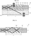
- Fig. 13 is a longitudinal sectional view illustrating a configuration of a conventional cladding mode stripper 10.
- the cladding mode stripper 10 is constituted by a high-refractive-index resin part 101 which covers a portion of an inner cladding 52 of an optical fiber 5 which portion is exposed in a coating-removed section I.
- the high-refractive-index resin part 101 is made of a light-transmitting resin having a refractive index not less than that of the inner cladding 52 of the optical fiber 5. This allows cladding mode light confined in the inner cladding 52 of the optical fiber 5 to leak into the high-refractive-index resin part 101 in the coating-removed section I.
- Patent Literature 1 discloses a cladding mode stripper provided with a heat dissipation mechanism or a cooling mechanism.
- Patent Literature 2 discloses a cladding mode stripper including a high-refractive-index resin part having a refractive index that gradually increases along a light propagation direction.
- part of cladding mode light which part has leaked out from an optical fiber in a coating-removed section may propagate inside a high-refractive-index resin part while being repeatedly reflected by a surface of the high-refractive-index resin part.
- the cladding mode light propagating inside the high-refractive-index resin part may cause the high-refractive-index resin part to generate heat and may degrade the high-refractive-index resin part, accordingly.
- the cladding mode power is as high as 10 W.
- a 10 W cladding mode is converted into heat in a high-refractive-index resin part having a length of several millimeters to several centimeters, a temperature rise enough to degrade the high-refractive-index resin part may occur.
- the present invention was made in view of the above problem, and an object thereof is to provide a cladding mode stripper that is arranged such that heat generation of a high-refractive-index resin part is less likely to occur as compared with a conventional cladding mode stripper.
- a cladding mode stripper in accordance with an aspect of the present invention is a cladding mode stripper, including a resin part which covers a coating-removed section of an optical fiber and has a refractive index not less than that of an outermost shell of the optical fiber in the coating-removed section, the resin part including an incident angle reducing structure formed on a surface of the resin part, the incident angle reducing structure being for reducing an incident angle or an average incident angle at which cladding mode light that has entered the resin part from the optical fiber enters the surface.
- a cladding mode stripper in accordance with an aspect of the present invention is a cladding mode stripper, including: a resin part which covers a coating-removed section of an optical fiber and has a refractive index not less than that of an outermost shell of the optical fiber in the coating-removed section; and a transparent member which supports the resin part and has a refractive index matching that of the resin part, the transparent member including a rough surface in a region of a surface of the transparent member which region is opposite to an interface between the transparent member and the resin part, cladding mode light that has entered the transparent member from the optical fiber through the resin part being scattered by the rough surface so that an average propagation angle of the cladding mode light is increased.
- a cladding mode stripper that is arranged such that heat generation of a high-refractive-index resin part is less likely to occur as compared with a conventional cladding mode stripper.
- Fig. 1 a configuration of a cladding mode stripper 1 in accordance with Embodiment 1 of the present invention.
- (a) of Fig. 1 is a longitudinal sectional view of the cladding mode stripper 1 and
- (b) of Fig. 1 is a transverse sectional view of the cladding mode stripper 1.
- the cladding mode stripper 1 includes (i) a high-refractive-index resin part 11 which covers a coating-removed section I of an optical fiber 5 and (ii) a reinforcement member 12 which supports the high-refractive-index resin part 11.
- the reinforcement member 12 is, for example, a rectangular parallelepiped member on an upper surface of which a V-shaped groove 121 is formed.
- the reinforcement member 12 is made of a non-transparent material (e.g., alumina). Alumina has a high thermal conductivity, a low linear expansion coefficient, and good processability, and therefore is suitable as a material of the reinforcement member 12.
- the high-refractive-index resin part 11 is obtained, for example, by curing resin injected into the V-shaped groove 121 of the reinforcement member 12.
- the high-refractive-index resin part 11 is made of a light-transmitting resin having a refractive index not less than that of an outermost shell of the optical fiber 5 in the coating-removed section I.
- the optical fiber 5 is made of, for example, a core 51 made of glass, an inner cladding 52 made of glass and covering a circumferential surface of the core 51, an outer cladding 53 made of a resin and covering an outer circumferential surface of the inner cladding 52, and a coating 54 made of a resin and covering an outer circumferential surface of the outer cladding 53.
- the outer cladding 53 and the coating 54 are removed so that the inner cladding 52 serves as the outermost shell.
- the high-refractive-index resin part 11 is made of a resin having a refractive index higher than that of the inner cladding 52 and covers the outer circumferential surface of the inner cladding 52 in the coating-removed section I.
- the cladding mode stripper 1 is characterized in that a planar prism (Fresnel prism) 111p is formed on a portion of a surface of the high-refractive-index resin part 11 which portion constitutes an interface between the high-refractive-index resin part 11 and the reinforcement member 12, the planar prism 111p being constituted by inclined surfaces 111a and vertical surfaces 111b alternately arranged along an optical axis of the optical fiber 5.
- the inclined surfaces 111a each face a light-entrance end and make, for example, an angle of 45° with the optical axis of the optical fiber 5.
- the vertical surfaces 111b each face a light-exit end and make, for example, an angle of 90° with the optical axis of the optical fiber 5.
- a region constituting an interface between the high-refractive-index resin part 11 and the reinforcement member 12 is referred to as a first region 111
- a region constituting an interface between the high-refractive-index resin part 11 and the air is referred to as a second region 112.
- a region in which the planar prism 111p is formed is included in the first region 111 and is opposite to the second region 112.
- cladding mode light that has entered the high-refractive-index resin part 11 from the optical fiber 5 is reflected, by the first region 111 in which the planar prism 111p is formed as described above, so that a propagation angle (an angle between an optical axis of the cladding mode light and the optical axis of the optical fiber 5 (acute angle)) of the cladding mode light is increased.
- an incident angle (an angle between an optical axis of the cladding mode light and a normal line of the second region 112 (acute angle)) at which the cladding mode light reflected by the first region 111 enters the second region 112 is reduced as compared with a case in which no planar prism is formed in the first region 111. That is, the planar prism 111p formed in the first region 111 functions as an incident angle reducing structure for reducing the incident angle at which the cladding mode light enters the second region 112.
- a reflectance of the second region 112 in reflecting cladding mode light that has been reflected by the first region 111 is reduced as compared with a case in which no planar prism is formed in the first region 111.
- a distance by which cladding mode light propagates inside the high-refractive-index resin part 11 while being repeatedly reflected by the surface of the high-refractive-index resin part 11 is reduced as compared with a case in which no planar prism is formed in the first region 111.
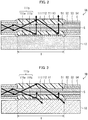
- FIG. 2 is a longitudinal sectional view of the cladding mode stripper 1A.
- the cladding mode stripper 1 (see Fig. 1 ) and the cladding mode stripper 1A in accordance with Modified Example 1 differ from each other in the following point.
- the second region 112 On the surface of the high-refractive-index resin part 11 of the cladding mode stripper 1, the second region 112 is exposed, whereas on a surface of a high-refractive-index resin part 11 of the cladding mode stripper 1A, the second region 112 is coated with an antireflection (AR) coating 113 which serves as an antireflection film.
- the AR coating 113 is preferably made of a material having a low refractive index and can be, for example, a fluorine-based resin, magnesium fluoride, or the like.
- the presence of the AR coating 113 with which the second region 112 is coated further reduces a reflectance of the second region 112 in reflecting cladding mode light that has been reflected by the first region 111. Further, since a planar prism is formed in the first region 111, an incident angle at which cladding mode light enters the AR coating 113 is reduced, so that an antireflection property of the AR coating 113 is exhibited more easily. As a result, a distance by which cladding mode light propagates inside the high-refractive-index resin part 11 while being repeatedly reflected by a surface of the high-refractive-index resin part 11 is further reduced. This enables even more effective prevention of heat generation and degradation of the high-refractive-index resin part 11 which are caused by cladding mode light propagating inside the high-refractive-index resin part 11.
- a cladding mode stripper 1B in accordance with Modified Example 2 will be described below with reference to Fig. 3.
- Fig. 3 is a longitudinal sectional view of the cladding mode stripper 1B.
- the cladding mode stripper 1 (see Fig. 1 ) and the cladding mode stripper 1B in accordance with Modified Example 2 differ from each other in the following point.
- the reinforcement member 12 is made of a non-transparent material (e.g., alumina), whereas in the cladding mode stripper 1B, a reinforcement member 12 is made of a transparent material (e.g., quartz or aluminum nitride).
- a non-transparent material e.g., alumina
- a transparent material e.g., quartz or aluminum nitride
- the reinforcement member 12 is made of the transparent material, a reflectance of a first region 111 in reflecting cladding mode light that has entered a high-refractive-index resin part 11 is reduced due to light that enters the reinforcement member 12.
- the first region 111 has a reflectance of approximately 60% in reflecting cladding mode light that propagates through the high-refractive-index resin part 11 at a propagation angle of 2° and enters the first region 111 at an incident angle of 88°.
- an incident angle at which the cladding mode light enters the reinforcement member 12 is reduced as compared with a case in which no planar prism is formed in the first region 111.
- This increases a proportion of cladding mode light that enters the reinforcement member 12 without being reflected by the first region 111 and (ii) reduces a proportion of light that is reflected by the first region 111 and returns to the high-refractive-index resin part 11.
- a distance by which cladding mode light propagates inside the high-refractive-index resin part 11 while being repeatedly reflected by a surface of the high-refractive-index resin part 11 is further reduced. This enables even more effective prevention of heat generation and degradation of the high-refractive-index resin part 11 which are caused by cladding mode light propagating inside the high-refractive-index resin part 11.
- an incident angle reducing structure formed on a surface of a high-refractive-index resin part may be (i) a surface structure that is formed, passively or heteronomously as a reflection of a surface shape of a reinforcement member, in a region constituting an interface between the high-refractive-index resin part and the reinforcement member or (ii) a surface structure that is formed, actively or autonomously, in a region that does not constitute an interface between the high-refractive-index resin part and the reinforcement member.
- Embodiment 1 is an example in which the planar prism 111p formed passively or heteronomously on the surface of the high-refractive-index resin part 11 is used as an incident angle reducing structure.
- Embodiment 2 which will be described later, is an example in which a planar prism 212p formed actively or autonomously on a surface of a high-refractive-index resin part 21 is used as an incident angle reducing structure (see Fig. 4 ).
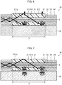
- Fig. 4 a configuration of a cladding mode stripper 2 in accordance with Embodiment 2 of the present invention.
- (a) of Fig. 2 is a longitudinal sectional view of the cladding mode stripper 2 and
- (b) of Fig. 2 is a transverse sectional view of the cladding mode stripper 2.
- the cladding mode stripper 2 includes (i) the high-refractive-index resin part 21 which covers a coating-removed section I of an optical fiber 5 and (ii) a reinforcement member 22 which supports the high-refractive-index resin part 21.
- the reinforcement member 22 is, for example, a rectangular parallelepiped member on an upper surface of which a V-shaped groove 221 is formed.
- the reinforcement member 22 is made of a non-transparent material (e.g., alumina).
- the high-refractive-index resin part 21 is obtained, for example, by curing resin injected into the V-shaped groove 221 of the reinforcement member 22.
- the high-refractive-index resin part 21 is made of a light-transmitting resin having a refractive index not less than that of an outermost shell of the optical fiber 5 in the coating-removed section I.
- the optical fiber 5 is made of, for example, a core 51 made of glass, an inner cladding 52 made of glass and covering a circumferential surface of the core 51, an outer cladding 53 made of a resin and covering an outer circumferential surface of the inner cladding 52, and a coating 54 made of a resin and covering an outer circumferential surface of the outer cladding 53.
- the outer cladding 53 and the coating 54 are removed so that the inner cladding 52 serves as the outermost shell.
- the high-refractive-index resin part 21 is made of a resin having a refractive index higher than that of the inner cladding 52 and covers the outer circumferential surface of the inner cladding 52 in the coating-removed section I.
- the cladding mode stripper 2 is characterized in that the planar prism (Fresnel prism) 212p is formed on a portion of a surface of the high-refractive-index resin part 21 which portion constitutes an interface between the high-refractive-index resin part 21 and the air, the planar prism 212p being constituted by vertical surfaces 212a and inclined surfaces 212b alternately arranged along an optical axis of the optical fiber 5.
- the vertical surfaces 212a each face a light-entrance end and make, for example, an angle of 90° with the optical axis of the optical fiber 5.
- the inclined surfaces 212b each face a light-exit end and make, for example, an angle of 45° with the optical axis of the optical fiber 5.
- a region constituting an interface between the high-refractive-index resin part 21 and the reinforcement member 22 is referred to as a first region 211, and a region constituting an interface between the high-refractive-index resin part 21 and the air is referred to as a second region 212.
- a region in which the planar prism 212p is formed is included in the second region 212 and is opposite to the first region 211.
- the provision of the planar prism 212p in the second region 212 reduces an incident angle at which cladding mode light reflected by the first region 211 enters the second region 212. That is, the planar prism 212p formed in the second region 212 functions as an incident angle reducing structure for reducing the incident angle at which the cladding mode light enters the second region 212.
- a reflectance of the second region 212 in reflecting cladding mode light reflected by the first region 211 is reduced as compared with a case in which no planar prism is formed in the second region 212.
- a distance by which cladding mode light propagates inside the high-refractive-index resin part 21 while being repeatedly reflected by the surface of the high-refractive-index resin part 21 is reduced as compared with a case in which no planar prism is formed in the second region 212.
- Fig. 5 a configuration of a cladding mode stripper 3 in accordance with Embodiment 3 of the present invention.
- (a) of Fig. 5 is a longitudinal sectional view of the cladding mode stripper 3 and
- (b) of Fig. 5 is a transverse sectional view of the cladding mode stripper 3.
- the cladding mode stripper 3 includes (i) the high-refractive-index resin part 31 which covers a coating-removed section I of an optical fiber 5 and (ii) a reinforcement member 32 which supports the high-refractive-index resin part 31.
- the reinforcement member 32 is, for example, a rectangular parallelepiped member on an upper surface of which a V-shaped groove 321 is formed.
- the reinforcement member 32 is made of a non-transparent material (e.g., alumina).
- the high-refractive-index resin part 31 is obtained, for example, by curing resin injected into the V-shaped groove 321 of the reinforcement member 32.
- the high-refractive-index resin part 31 is made of a light-transmitting resin having a refractive index not less than that of an outermost shell of the optical fiber 5 in the coating-removed section I.
- the optical fiber 5 is made of, for example, a core 51 made of glass, an inner cladding 52 made of glass and covering a circumferential surface of the core 51, an outer cladding 53 made of a resin and covering an outer circumferential surface of the inner cladding 52, and a coating 54 made of a resin and covering an outer circumferential surface of the outer cladding 53.
- the outer cladding 53 and the coating 54 are removed so that the inner cladding 52 serves as the outermost shell.
- the high-refractive-index resin part 31 is made of a resin having a refractive index higher than that of the inner cladding 52 and covers the outer circumferential surface of the inner cladding 52 in the coating-removed section I.
- the cladding mode stripper 3 is characterized in that the rough surface 311q is formed on a portion of a surface of the high-refractive-index resin part 31 which portion constitutes an interface between the high-refractive-index resin part 31 and the reinforcement member 32, the rough surface 311q having an average roughness (e.g., arithmetic average roughness) Ra greater than ⁇ /2.
- ⁇ is a wavelength of cladding mode light propagating trough the high-refractive-index resin part 31.
- An average roughness Ra of a region on a surface means a value obtained by averaging, across the region, absolute values of deviations of the surface from an ideal surface.
- a region constituting an interface between the high-refractive-index resin part 31 and the reinforcement member 32 is referred to as a first region 311, and a region constituting an interface between the high-refractive-index resin part 31 and the air is referred to as a second region 312.
- a region in which the rough surface 311q is formed is included in the first region 311 and is opposite to the second region 312.
- cladding mode light that has entered the high-refractive-index resin part 31 from the optical fiber 5 is scattered, by the first region 311 in which the rough surface 311q is formed as described above, so that an average propagation angle (a mean value of a distribution of propagation angles of scattered light generated when the cladding mode light enters the first region 311) is increased.
- an intensity distribution of light scattered by the rough surface 311q having an average roughness Ra greater than ⁇ /2 follows Lambert's law, so that an intensity of light scattered in a direction normal to the rough surface 311q is higher than that of light scattered in a direction other than the direction normal to the rough surface 311q.
- I0 is an intensity of light scattered in a direction normal to the surface
- I ⁇ is an intensity of light scattered in a direction that makes an angle of ⁇ with the direction normal to the surface.
- an average incident angle (a mean value of a distribution of incident angles at which cladding mode light scattered by the first region 311 enters the second region 312) at which cladding mode light scattered by the first region 311 enters the second region 312 is reduced as compared with a case in which the first region 311 does not include a rough surface. That is, the rough surface 311q formed in the first region 311 functions as an incident angle reducing structure for reducing the average incident angle at which the cladding mode light enters the second region 312.
- an average reflectance of the second region 312 in reflecting cladding mode light that has been scattered by the first region 311 is reduced as compared with a case in which the first region 311 does not include a rough surface.
- an average distance by which cladding mode light propagates inside the high-refractive-index resin part 31 while being repeatedly reflected by the surface of the high-refractive-index resin part 31 is reduced as compared with a case in which the first region 311 does not include a rough surface.
- FIG. 6 is a longitudinal sectional view of the cladding mode stripper 3A.
- the cladding mode stripper 3 (see Fig. 5 ) and the cladding mode stripper 3A in accordance with Modified Example 3 differ from each other in the following point.
- the second region 312 On the surface of the high-refractive-index resin part 31 of the cladding mode stripper 3, the second region 312 is exposed, whereas on a surface of a high-refractive-index resin part 31 of the cladding mode stripper 3A, a second region 312 is coated with an AR coating 313.
- the presence of the AR coating with which the second region 312 is coated further reduces a reflectance of the second region 312 in reflecting cladding mode light that has been reflected by the first region 311. Further, since the first region 311 includes a rough surface, an incident angle at which cladding mode light enters the AR coating 313 is reduced, so that an antireflection property of the AR coating 313 is exhibited more easily. As a result, a distance by which cladding mode light propagates inside the high-refractive-index resin part 31 while being repeatedly reflected by the surface of the high-refractive-index resin part 31 is further reduced. This enables even more effective prevention of heat generation and degradation of the high-refractive-index resin part high-refractive-index resin part 31 which are caused by cladding mode light propagating inside the high-refractive-index resin part 31.
- a cladding mode stripper 3B in accordance with Modified Example 2 will be described below with reference to Fig. 7.
- Fig. 7 is a longitudinal sectional view of the cladding mode stripper 3B.
- the cladding mode stripper 3 (see Fig. 5 ) and the cladding mode stripper 3B in accordance with Modified Example 2 differ from each other in the following point.
- the reinforcement member 32 is made of a non-transparent material (e.g., alumina), whereas in the cladding mode stripper 3B, a reinforcement member 32 is made of a transparent material (e.g., quartz or aluminum nitride).
- a non-transparent material e.g., alumina
- a transparent material e.g., quartz or aluminum nitride
- the reinforcement member 32 is made of the transparent material, a backward scattering rate (a proportion of cladding mode light that is scattered toward the high-refractive-index resin part 31) of a first region 311 in scattering cladding mode light that has entered a high-refractive-index resin part 31 is reduced.
- the backward scattering rate is typically not more than 50%.
- the first region 311 does not include a rough surface, most of cladding mode light entering the first region 311 at a wide incident angle is reflected.
- the first region 111 has a reflectance of approximately 60% in reflecting cladding mode light that propagates through the high-refractive-index resin part 31 at a propagation angle of 2° and enters the first region 311 at an incident angle of 88°.
- the refractive index difference between the high-refractive-index resin part 31 and the reinforcement member 32 increases, a reflectance of the first region 111 in reflecting cladding mode light increases.
- the first region 311 includes a rough surface
- an amount of cladding mode light that propagates inside the high-refractive-index resin part 31 while being repeatedly reflected by the surface of the high-refractive-index resin part 31 is further reduced. This enables even more effective prevention of heat generation and degradation of the high-refractive-index resin part 31 which are caused by cladding mode light propagating inside the high-refractive-index resin part 31.
- Fig. 8 a configuration of a cladding mode stripper 4 in accordance with Embodiment 4 of the present invention.
- (a) of Fig. 8 is a longitudinal sectional view of the cladding mode stripper 4 and
- (b) of Fig. 8 is a transverse sectional view of the cladding mode stripper 4.
- the cladding mode stripper 4 includes (i) a high-refractive-index resin part 41 which covers a coating-removed section I of an optical fiber 5 and (ii) two transparent reinforcement members, namely, transparent reinforcement members 42 to 43, which support the high-refractive-index resin part 41.
- the first transparent reinforcement member 42 is, for example, a rectangular parallelepiped member on an upper surface of which a V-shaped groove 421 is formed.
- the first transparent reinforcement member 42 is made of a transparent material (e.g., quartz or the like) having a refractive index matching that of the high-refractive-index resin part 41.
- the high-refractive-index resin part 41 is obtained, for example, by curing resin injected into the V-shaped groove 421 of the transparent reinforcement member 42.
- the high-refractive-index resin part 41 is made of a light-transmitting resin having a refractive index not less than that of an outermost shell of the optical fiber 5 in the coating-removed section I.
- the second transparent reinforcement member 43 is, for example, a rectangular parallelepiped member.
- the second transparent reinforcement member 43 is made of a transparent material (e.g., quartz or the like) having a refractive index matching that of the high-refractive-index resin part 41.
- the second transparent reinforcement member 43 is bonded to the first transparent reinforcement member 42 so that a bottom surface of the second transparent reinforcement member 43 is in contact with an upper surface of the first transparent reinforcement member 42.
- the second transparent reinforcement member 43 serves as a lid for sealing the V-shaped groove 421 formed on the upper surface of the first transparent reinforcement member 42.
- the optical fiber 5 is made of, for example, a core 51 made of glass, an inner cladding 52 made of glass and covering a circumferential surface of the core 51, an outer cladding 53 made of a resin and covering an outer circumferential surface of the inner cladding 52, and a coating 54 made of a resin and covering an outer circumferential surface of the outer cladding 53.
- the outer cladding 53 and the coating 54 are removed so that the inner cladding 52 serves as the outermost shell.
- the high-refractive-index resin part 41 is made of a resin having a refractive index higher than that of the inner cladding 52 and covers the outer circumferential surface of the inner cladding 52 in the coating-removed section I.
- a first feature of the cladding mode stripper 4 is that the refractive index of the first transparent reinforcement member 42 and the refractive index of the second transparent reinforcement member 43 each match the refractive index of the high-refractive-index resin part 41. Accordingly, most of cladding mode light that has entered the high-refractive-index resin part 41 from the optical fiber 5 either (i) passes through an interface between the high-refractive-index resin part 41 and the first transparent reinforcement member 42 so as to enter the first transparent reinforcement member 42 or (ii) passes through an interface between the high-refractive-index resin part 41 and the second transparent reinforcement member 43 so as to enter the second transparent reinforcement member 43.
- a half or more of cladding mode light that propagates through the high-refractive-index resin part 41 at a propagation angle of 2° and enters the transparent reinforcement member 43 at an incident angle of 88° either (i) passes through the interface between the high-refractive-index resin part 41 and the first transparent reinforcement member 42 so as to enter the first transparent reinforcement member 42 or (ii) passes through the interface between the high-refractive-index resin part 41 and the second transparent reinforcement member 43 so as to enter the second transparent reinforcement member 43.
- a distance by which cladding mode light propagates inside the high-refractive-index resin part 41 while being repeatedly reflected by the interface between the high-refractive-index resin part 41 and the first transparent reinforcement member 42 and the interface between the high-refractive-index resin part 41 and the second transparent reinforcement member 43 is reduced as compared with a case in which neither of the refractive indices of the first transparent reinforcement member 42 and the second transparent reinforcement member 43 does not match the refractive index of the high-refractive-index resin part 41.
- a second feature of the cladding mode stripper 4 is that a region 421 of a surface of the first transparent reinforcement member 42 which region 421 is opposite to the interface between the first transparent reinforcement member 42 and the high-refractive-index resin part 41 includes a rough surface, and a region 431 of a surface of the second transparent reinforcement member 43 which region 431 is opposite to the interface between the second transparent reinforcement member 43 and the high-refractive-index resin part 41 includes a rough surface.
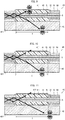
- Fig. 9 is a longitudinal sectional view of the cladding mode stripper 4A.
- the cladding mode stripper 4A is identical to the cladding mode stripper 4 (see Fig. 8 ) except that (i) the cladding mode stripper 4A has no second transparent reinforcement member 43 and (ii) a region 411 on a surface of a high-refractive-index resin part 41, which region 411 is opposite to an interface between the high-refractive-index resin part 41 and a first transparent reinforcement member 42, includes a rough surface. Most of cladding mode light that has entered is scattered in the region 411.
- the region 411 which is an interface between the high-refractive-index resin part 41 and the air, is prevented from reentering the high-refractive-index resin part 41 and is emitted to an outside of the cladding mode stripper 4.
- the rough surface formed in the region 411 functions as an incident angle reducing structure for reducing an average incident angle at which cladding mode light enters the interface between the high-refractive-index resin part 41 and the transparent reinforcement member 42 and enters a region 421 which is opposite to the region 411.
- the first region 421 also includes a rough surface, so that a component having a wide incident angle among the cladding mode light is also scattered instead of being reflected.
- a distance by which cladding mode light propagates inside the high-refractive-index resin part 41 while being repeatedly reflected by the surface of the high-refractive-index resin part 41 is further reduced. This enables even more effective prevention of heat generation and degradation of the high-refractive-index resin part 41 which are caused by cladding mode light propagating inside the high-refractive-index resin part 41.
- Fig. 10 is a longitudinal sectional view of the cladding mode stripper 4B.
- the cladding mode stripper 4B is identical to the cladding mode stripper 4 (see Fig. 8 ) except that (i) the cladding mode stripper 4B has no second transparent reinforcement member 43 and (ii) a region 411 on a surface of a high-refractive-index resin part 41, which region 411 is opposite to an interface between the high-refractive-index resin part 41 and a first transparent reinforcement member 42, is coated with an AR coating.
- the region 421 has a light scattering surface, so that an incident angle at which cladding mode light enters the AR coating is reduced. This allows an antireflection property of the AR coating to be exhibited more easily. As a result, a distance by which cladding mode light propagates inside the high-refractive-index resin part 41 while being repeatedly reflected by the surface of the high-refractive-index resin part 41 is further reduced. This enables even more effective prevention of heat generation and degradation of the high-refractive-index resin part 41 which are caused by cladding mode light propagating inside the high-refractive-index resin part 41.
- Fig. 11 is a longitudinal sectional view of the cladding mode stripper 4C.
- the cladding mode stripper 4C is identical to the cladding mode stripper 4B (see Fig. 10 ) except that a planar prism is formed in a region 412 on a surface of a high-refractive-index resin part 41, which region 412 constitutes an interface between the high-refractive-index resin part 41 and a transparent reinforcement member 42.
- the planar prism formed in the region 412 functions as an incident angle reducing structure for reducing an average incident angle at which cladding mode light enters the region 412.
- a reflectance of the high-refractive-index resin part 41 in reflecting cladding mode light entering the interface between the high-refractive-index resin part 41 and the transparent reinforcement member 42 is reduced. Further, a propagation angle of cladding mode light reflected by the region 412 is increased. As a result, a distance by which cladding mode light propagates inside the high-refractive-index resin part 41 while being repeatedly reflected by the surface of the high-refractive-index resin part 41 is further reduced. This enables even more effective prevention of heat generation and degradation of the high-refractive-index resin part 41 which are caused by cladding mode light propagating inside the high-refractive-index resin part 41.
- Fig. 12 is a longitudinal sectional view of the cladding mode stripper 4D.
- the cladding mode stripper 4D is identical to the cladding mode stripper 4A (see Fig. 9 ) except that a planar prism is formed in a region 412 on a surface of a high-refractive-index resin part 41, which region 412 constitutes an interface between the high-refractive-index resin part 41 and a transparent reinforcement member 42.
- the planar prism formed in the region 412 functions as an incident angle reducing structure for reducing an average incident angle at which cladding mode light enters the region 412.
- a reflectance of the high-refractive-index resin part 41 in reflecting cladding mode light entering an interface between the high-refractive-index resin part 41 and the transparent reinforcement member 42 is reduced. Further, a propagation angle of cladding mode light reflected by the region 412 is increased. As a result, a distance by which cladding mode light propagates inside the high-refractive-index resin part 41 while being repeatedly reflected by the surface of the high-refractive-index resin part 41 is further reduced. This enables even more effective prevention of heat generation and degradation of the high-refractive-index resin part 41 which are caused by cladding mode light propagating inside the high-refractive-index resin part 41.
- a cladding mode stripper in accordance with the present embodiment is a cladding mode stripper, including a resin part which covers a coating-removed section of an optical fiber and has a refractive index not less than that of an outermost shell of the optical fiber in the coating-removed section, the resin part including an incident angle reducing structure formed on a surface of the resin part which surface is opposite to an interface between the resin part and the outermost shell, the incident angle reducing structure being for reducing an incident angle or an average incident angle at which cladding mode light that has entered the resin part from the optical fiber enters the surface.
- the cladding mode stripper in accordance with the present embodiment is preferably arranged such that the incident angle reducing structure is a rough surface which reduces an average incident angle at which the cladding mode light scattered by the incident angle reducing structure enters a region of the surface which region is opposite to the incident angle reducing structure.
- the cladding mode stripper in accordance with the present embodiment is preferably arranged such that the rough surface scatters the cladding mode light so as to increase an average propagation angle of the cladding mode light.
- the cladding mode stripper in accordance with the present embodiment is preferably arranged such that an average roughness Ra of the rough surface is greater than ⁇ /2 where ⁇ is a wavelength of the cladding mode light propagating trough the resin part.
- the cladding mode stripper in accordance with the present embodiment is preferably arranged such that the incident angle reducing structure is a planar prism which reduces an incident angle at which the cladding mode light reflected by the incident angle reducing structure enters a region of the surface which region is opposite to the incident angle reducing structure.
- the cladding mode stripper in accordance with the present embodiment is preferably arranged such that the planar prism reflects the cladding mode light so as to increase a propagation angle of the cladding mode light.
- the cladding mode stripper in accordance with the present embodiment is preferably arranged such that the incident angle reducing structure is a planar prism which reduces an incident angle at which the cladding mode light enters the incident angle reducing structure.
- the cladding mode stripper in accordance with the present embodiment is preferably arranged such that the cladding mode stripper further includes a transparent member which supports the resin part and has a refractive index matching that of the resin part, the transparent member including a rough surface formed in a region of a surface of the transparent member which region is opposite to an interface between the transparent member and the resin part, cladding mode light that has entered the transparent member from the optical fiber through the resin part being scattered by the rough surface so that an average propagation angle of the cladding mode light is increased.
- the cladding mode stripper in accordance with the present embodiment is preferably arranged such that an average roughness Ra of the rough surface is greater than ⁇ /2 where ⁇ is a wavelength of the cladding mode light propagating trough the transparent member.
- the cladding mode stripper in accordance with the present embodiment is preferably arranged such that a refractive index difference between the resin part and the transparent member is not more than 2%.
- the cladding mode stripper in accordance with the present embodiment is preferably arranged such that the region of the surface of the resin part which region is opposite to the interface between the resin part and the transparent member includes a rough surface or is coated with an AR coating.
- a cladding mode stripper in accordance with the present embodiment is a cladding mode stripper, including: a resin part which covers a coating-removed section of an optical fiber and has a refractive index not less than that of an outermost shell of the optical fiber in the coating-removed section; and a transparent member which supports the resin part and has a refractive index matching that of the resin part, the transparent member including a rough surface in a region of a surface of the transparent member which region is opposite to an interface between the transparent member and the resin part, cladding mode light that has entered the transparent member from the optical fiber through the resin part being scattered by the rough surface so that an average propagation angle of the cladding mode light is increased.
- the cladding mode stripper in accordance with the present embodiment is preferably arranged such that an average roughness Ra of the rough surface is greater than ⁇ /2 where ⁇ is a wavelength of the cladding mode light propagating trough the transparent member.
- the cladding mode stripper in accordance with the present embodiment is preferably arranged such that a refractive index difference between the resin part and the transparent member is not more than 2%.
- the cladding mode stripper in accordance with the present embodiment is preferably arranged such that a region of a surface of the resin part which region is opposite to the interface between the resin part and the transparent member includes a rough surface or is coated with an AR coating.
- the present invention is not limited to the embodiments, but can be altered by a skilled person in the art within the scope of the claims.
- the present invention also encompasses, in its technical scope, any embodiment or the like derived by combining technical means disclosed in differing embodiments and modified examples.
Landscapes
- Physics & Mathematics (AREA)
- General Physics & Mathematics (AREA)
- Optics & Photonics (AREA)
- Optical Couplings Of Light Guides (AREA)
- Optical Fibers, Optical Fiber Cores, And Optical Fiber Bundles (AREA)
- Lasers (AREA)
Abstract
Description
- The present invention relates to a cladding mode stripper for removing cladding mode light from an optical fiber.
- In the field of material processing in which metal materials or the like are processed (e.g., cut, welded, shaved), laser processing using laser light has been increasingly used, replacing machining using a blade, a drill, or the like. As a laser device for use in laser processing, a fiber laser has been attracting attention. For processing that requires laser light with higher power, a fiber laser system including a plurality of fiber lasers and a combiner for combining laser light waves generated by the respective plurality of fiber lasers is used.
- The fiber laser is a laser device including, as a resonator, a pump-gain fiber that has fiber Bragg gratings connected to the opposite ends thereof, wherein one of the fiber Bragg gratings serves as a mirror and the other serves as a half mirror. The pump-gain fiber is typically a double cladding fiber whose core is doped with a rare-earth element such as Yb. Signal light generated by the resonator is guided to an object to be processed, with use of a delivery fiber connected to the fiber Bragg grating serving as the half mirror. The delivery fiber is typically a double cladding fiber as well.
- In the fiber laser, an optical path of laser light generated by the resonator is constituted by the pump-gain fiber, the fiber Bragg grating, and the delivery fiber. The optical path includes at least a connection point between the pump-gain fiber and the fiber Bragg grating and a connection point between the fiber Bragg grating and the delivery fiber. At any of the connection points constituting the optical path, in a case where the optical fibers at the connection point have mismatch of cores (difference in core diameter, axial misalignment between the cores, or the like), cladding mode light is excited in a cladding of a downstream one of the optical fibers. For example, in a case where cores mismatch at the connection point between the fiber Bragg grating and the delivery fiber, cladding mode light is excited in a cladding of the delivery fiber. Further, also in a case where a disturbance such as lateral pressure or bending is applied to an optical fiber constituting the optical path, a higher order mode component of laser light guided through the core leaks into a cladding, so that cladding mode light is excited. In the fiber laser system, the combiner can be a source of cladding mode light, and a connection point between the combiner and an optical fiber constituting the optical path can also be a source of cladding mode light.
- Cladding mode light which is guided through a cladding of an optical fiber constituting the optical path (i) causes a coating of the optical fiber or of an optical fiber downstream of the optical fiber to generate heat and (ii) causes a component of a processing head connected to an exit end of the delivery fiber to generate heat. That is, cladding mode light guided through a cladding of an optical fiber constituting the optical path can cause a decrease in reliability of the fiber laser or the fiber laser system. In view of this, an optical fiber constituting the optical path is provided with a cladding mode stripper for removing cladding mode light.
-
Fig. 13 is a longitudinal sectional view illustrating a configuration of a conventionalcladding mode stripper 10. Thecladding mode stripper 10 is constituted by a high-refractive-index resin part 101 which covers a portion of aninner cladding 52 of anoptical fiber 5 which portion is exposed in a coating-removed section I. The high-refractive-index resin part 101 is made of a light-transmitting resin having a refractive index not less than that of theinner cladding 52 of theoptical fiber 5. This allows cladding mode light confined in theinner cladding 52 of theoptical fiber 5 to leak into the high-refractive-index resin part 101 in the coating-removed section I. -
Patent Literature 1 discloses a cladding mode stripper provided with a heat dissipation mechanism or a cooling mechanism.Patent Literature 2 discloses a cladding mode stripper including a high-refractive-index resin part having a refractive index that gradually increases along a light propagation direction. -
-
Patent Literature 1
Japanese Patent Application Publication, Tokukaihei, No.1-316705 -
Patent Literature 2
International Publication No.WO 2013/001734 - In a conventional cladding mode stripper, part of cladding mode light which part has leaked out from an optical fiber in a coating-removed section may propagate inside a high-refractive-index resin part while being repeatedly reflected by a surface of the high-refractive-index resin part. The cladding mode light propagating inside the high-refractive-index resin part may cause the high-refractive-index resin part to generate heat and may degrade the high-refractive-index resin part, accordingly.
- For example, in a case where 1% of laser light guided through a core of a fiber laser having an output of 1 kW becomes cladding mode light, the cladding mode power is as high as 10 W. In a case where a 10 W cladding mode is converted into heat in a high-refractive-index resin part having a length of several millimeters to several centimeters, a temperature rise enough to degrade the high-refractive-index resin part may occur.
- The present invention was made in view of the above problem, and an object thereof is to provide a cladding mode stripper that is arranged such that heat generation of a high-refractive-index resin part is less likely to occur as compared with a conventional cladding mode stripper.
- In order to attain the object, a cladding mode stripper in accordance with an aspect of the present invention is a cladding mode stripper, including a resin part which covers a coating-removed section of an optical fiber and has a refractive index not less than that of an outermost shell of the optical fiber in the coating-removed section, the resin part including an incident angle reducing structure formed on a surface of the resin part, the incident angle reducing structure being for reducing an incident angle or an average incident angle at which cladding mode light that has entered the resin part from the optical fiber enters the surface.
- In order to attain the object, a cladding mode stripper in accordance with an aspect of the present invention is a cladding mode stripper, including: a resin part which covers a coating-removed section of an optical fiber and has a refractive index not less than that of an outermost shell of the optical fiber in the coating-removed section; and a transparent member which supports the resin part and has a refractive index matching that of the resin part, the transparent member including a rough surface in a region of a surface of the transparent member which region is opposite to an interface between the transparent member and the resin part, cladding mode light that has entered the transparent member from the optical fiber through the resin part being scattered by the rough surface so that an average propagation angle of the cladding mode light is increased.
- According to an aspect of the present invention, it is possible to provide a cladding mode stripper that is arranged such that heat generation of a high-refractive-index resin part is less likely to occur as compared with a conventional cladding mode stripper.
-
-
Fig. 1 is a longitudinal sectional view and a transverse sectional view each illustrating a configuration of a cladding mode stripper in accordance withEmbodiment 1 of the present invention. -
Fig. 2 is a longitudinal sectional view illustrating Modified Example 1 of the cladding mode stripper illustrated inFig. 1 . -
Fig. 3 is a longitudinal sectional view illustrating Modified Example 2 of the cladding mode stripper illustrated inFig. 1 . -
Fig. 4 is a longitudinal sectional view and a transverse sectional view each illustrating a configuration of a cladding mode stripper in accordance withEmbodiment 2 of the present invention. -
Fig. 5 is a longitudinal sectional view and a transverse sectional view each illustrating a configuration of a cladding mode stripper in accordance withEmbodiment 3 of the present invention. -
Fig. 6 is a longitudinal sectional view illustrating Modified Example 1 of the cladding mode stripper illustrated inFig. 5 . -
Fig. 7 is a longitudinal sectional view illustrating Modified Example 2 of the cladding mode stripper illustrated inFig. 5 . -
Fig. 8 is a longitudinal sectional view and a transverse sectional view each illustrating a configuration of a cladding mode stripper in accordance withEmbodiment 4 of the present invention. -
Fig. 9 is a longitudinal sectional view illustrating Modified Example 1 of the cladding mode stripper illustrated inFig. 8 . -
Fig. 10 is a longitudinal sectional view illustrating Modified Example 2 of the cladding mode stripper illustrated inFig. 8 . -
Fig. 11 is a longitudinal sectional view illustrating Modified Example 3 of the cladding mode stripper illustrated inFig. 8 . -
Fig. 12 is a longitudinal sectional view illustrating Modified Example 4 of the cladding mode stripper illustrated inFig. 8 . -
Fig. 13 is a longitudinal sectional view illustrating a configuration of a conventional cladding mode stripper. - The following description will discuss, with reference to
Fig. 1 , a configuration of acladding mode stripper 1 in accordance withEmbodiment 1 of the present invention. (a) ofFig. 1 is a longitudinal sectional view of thecladding mode stripper 1 and (b) ofFig. 1 is a transverse sectional view of thecladding mode stripper 1. - The
cladding mode stripper 1 includes (i) a high-refractive-index resin part 11 which covers a coating-removed section I of anoptical fiber 5 and (ii) areinforcement member 12 which supports the high-refractive-index resin part 11. Thereinforcement member 12 is, for example, a rectangular parallelepiped member on an upper surface of which a V-shaped groove 121 is formed. Thereinforcement member 12 is made of a non-transparent material (e.g., alumina). Alumina has a high thermal conductivity, a low linear expansion coefficient, and good processability, and therefore is suitable as a material of thereinforcement member 12. The high-refractive-index resin part 11 is obtained, for example, by curing resin injected into the V-shaped groove 121 of thereinforcement member 12. The high-refractive-index resin part 11 is made of a light-transmitting resin having a refractive index not less than that of an outermost shell of theoptical fiber 5 in the coating-removed section I. - The
optical fiber 5 is made of, for example, acore 51 made of glass, aninner cladding 52 made of glass and covering a circumferential surface of thecore 51, anouter cladding 53 made of a resin and covering an outer circumferential surface of theinner cladding 52, and acoating 54 made of a resin and covering an outer circumferential surface of theouter cladding 53. In the coating-removed section I, theouter cladding 53 and thecoating 54 are removed so that theinner cladding 52 serves as the outermost shell. The high-refractive-index resin part 11 is made of a resin having a refractive index higher than that of theinner cladding 52 and covers the outer circumferential surface of theinner cladding 52 in the coating-removed section I. - The
cladding mode stripper 1 is characterized in that a planar prism (Fresnel prism) 111p is formed on a portion of a surface of the high-refractive-index resin part 11 which portion constitutes an interface between the high-refractive-index resin part 11 and thereinforcement member 12, theplanar prism 111p being constituted byinclined surfaces 111a andvertical surfaces 111b alternately arranged along an optical axis of theoptical fiber 5. Theinclined surfaces 111a each face a light-entrance end and make, for example, an angle of 45° with the optical axis of theoptical fiber 5. Thevertical surfaces 111b each face a light-exit end and make, for example, an angle of 90° with the optical axis of theoptical fiber 5. Hereinafter, on the surface of the high-refractive-index resin part 11, a region constituting an interface between the high-refractive-index resin part 11 and thereinforcement member 12 is referred to as afirst region 111, and a region constituting an interface between the high-refractive-index resin part 11 and the air is referred to as asecond region 112. On the surface of the high-refractive-index resin part 11, a region in which theplanar prism 111p is formed is included in thefirst region 111 and is opposite to thesecond region 112. - In the high-refractive-
index resin part 11, cladding mode light that has entered the high-refractive-index resin part 11 from theoptical fiber 5 is reflected, by thefirst region 111 in which theplanar prism 111p is formed as described above, so that a propagation angle (an angle between an optical axis of the cladding mode light and the optical axis of the optical fiber 5 (acute angle)) of the cladding mode light is increased. As a result, in the high-refractive-index resin part 11, an incident angle (an angle between an optical axis of the cladding mode light and a normal line of the second region 112 (acute angle)) at which the cladding mode light reflected by thefirst region 111 enters thesecond region 112 is reduced as compared with a case in which no planar prism is formed in thefirst region 111. That is, theplanar prism 111p formed in thefirst region 111 functions as an incident angle reducing structure for reducing the incident angle at which the cladding mode light enters thesecond region 112. - Accordingly, in the high-refractive-
index resin part 11, a reflectance of thesecond region 112 in reflecting cladding mode light that has been reflected by thefirst region 111 is reduced as compared with a case in which no planar prism is formed in thefirst region 111. As a result, a distance by which cladding mode light propagates inside the high-refractive-index resin part 11 while being repeatedly reflected by the surface of the high-refractive-index resin part 11 is reduced as compared with a case in which no planar prism is formed in thefirst region 111. This enables effective prevention of heat generation and degradation of the high-refractive-index resin part 11 which are caused by cladding mode light propagating inside the high-refractive-index resin part 11. - The following description will discuss, with reference to
Figs. 2 and 3 , Modified Examples of thecladding mode stripper 1 in accordance withEmbodiment 1. - A cladding mode stripper 1A in accordance with Modified Example 1 will be described below with reference to
Fig. 2. Fig. 2 is a longitudinal sectional view of the cladding mode stripper 1A. The cladding mode stripper 1 (seeFig. 1 ) and the cladding mode stripper 1A in accordance with Modified Example 1 differ from each other in the following point. - Difference: On the surface of the high-refractive-
index resin part 11 of thecladding mode stripper 1, thesecond region 112 is exposed, whereas on a surface of a high-refractive-index resin part 11 of the cladding mode stripper 1A, thesecond region 112 is coated with an antireflection (AR) coating 113 which serves as an antireflection film. The AR coating 113 is preferably made of a material having a low refractive index and can be, for example, a fluorine-based resin, magnesium fluoride, or the like. - In the high-refractive-
index resin part 11 of the cladding mode stripper 1A, the presence of the AR coating 113 with which thesecond region 112 is coated further reduces a reflectance of thesecond region 112 in reflecting cladding mode light that has been reflected by thefirst region 111. Further, since a planar prism is formed in thefirst region 111, an incident angle at which cladding mode light enters the AR coating 113 is reduced, so that an antireflection property of the AR coating 113 is exhibited more easily. As a result, a distance by which cladding mode light propagates inside the high-refractive-index resin part 11 while being repeatedly reflected by a surface of the high-refractive-index resin part 11 is further reduced. This enables even more effective prevention of heat generation and degradation of the high-refractive-index resin part 11 which are caused by cladding mode light propagating inside the high-refractive-index resin part 11. - Next, a
cladding mode stripper 1B in accordance with Modified Example 2 will be described below with reference toFig. 3. Fig. 3 is a longitudinal sectional view of thecladding mode stripper 1B. The cladding mode stripper 1 (seeFig. 1 ) and thecladding mode stripper 1B in accordance with Modified Example 2 differ from each other in the following point. - Difference: In the
cladding mode stripper 1, thereinforcement member 12 is made of a non-transparent material (e.g., alumina), whereas in thecladding mode stripper 1B, areinforcement member 12 is made of a transparent material (e.g., quartz or aluminum nitride). - Since the
reinforcement member 12 is made of the transparent material, a reflectance of afirst region 111 in reflecting cladding mode light that has entered a high-refractive-index resin part 11 is reduced due to light that enters thereinforcement member 12. For example, in a case where a refractive index difference between the high-refractive-index resin part 11 and thereinforcement member 12 is 4%, thefirst region 111 has a reflectance of approximately 60% in reflecting cladding mode light that propagates through the high-refractive-index resin part 11 at a propagation angle of 2° and enters thefirst region 111 at an incident angle of 88°. Further, since a planar prism is formed in thefirst region 111, an incident angle at which the cladding mode light enters thereinforcement member 12 is reduced as compared with a case in which no planar prism is formed in thefirst region 111. This (i) increases a proportion of cladding mode light that enters thereinforcement member 12 without being reflected by thefirst region 111 and (ii) reduces a proportion of light that is reflected by thefirst region 111 and returns to the high-refractive-index resin part 11. As a result, a distance by which cladding mode light propagates inside the high-refractive-index resin part 11 while being repeatedly reflected by a surface of the high-refractive-index resin part 11 is further reduced. This enables even more effective prevention of heat generation and degradation of the high-refractive-index resin part 11 which are caused by cladding mode light propagating inside the high-refractive-index resin part 11. - Note that an incident angle reducing structure formed on a surface of a high-refractive-index resin part may be (i) a surface structure that is formed, passively or heteronomously as a reflection of a surface shape of a reinforcement member, in a region constituting an interface between the high-refractive-index resin part and the reinforcement member or (ii) a surface structure that is formed, actively or autonomously, in a region that does not constitute an interface between the high-refractive-index resin part and the reinforcement member. The above-described
Embodiment 1 is an example in which theplanar prism 111p formed passively or heteronomously on the surface of the high-refractive-index resin part 11 is used as an incident angle reducing structure.Embodiment 2, which will be described later, is an example in which aplanar prism 212p formed actively or autonomously on a surface of a high-refractive-index resin part 21 is used as an incident angle reducing structure (seeFig. 4 ).Embodiment 3, which will be described later, is an example in which arough surface 311q formed passively or heteronomously on a surface of a high-refractive-index resin part 31 is used as an incident angle reducing structure (seeFig. 5 ). - The following description will discuss, with reference to
Fig. 4 , a configuration of acladding mode stripper 2 in accordance withEmbodiment 2 of the present invention. (a) ofFig. 2 is a longitudinal sectional view of thecladding mode stripper 2 and (b) ofFig. 2 is a transverse sectional view of thecladding mode stripper 2. - The
cladding mode stripper 2 includes (i) the high-refractive-index resin part 21 which covers a coating-removed section I of anoptical fiber 5 and (ii) areinforcement member 22 which supports the high-refractive-index resin part 21. Thereinforcement member 22 is, for example, a rectangular parallelepiped member on an upper surface of which a V-shapedgroove 221 is formed. Thereinforcement member 22 is made of a non-transparent material (e.g., alumina). The high-refractive-index resin part 21 is obtained, for example, by curing resin injected into the V-shapedgroove 221 of thereinforcement member 22. The high-refractive-index resin part 21 is made of a light-transmitting resin having a refractive index not less than that of an outermost shell of theoptical fiber 5 in the coating-removed section I. - The
optical fiber 5 is made of, for example, a core 51 made of glass, aninner cladding 52 made of glass and covering a circumferential surface of the core 51, anouter cladding 53 made of a resin and covering an outer circumferential surface of theinner cladding 52, and acoating 54 made of a resin and covering an outer circumferential surface of theouter cladding 53. In the coating-removed section I, theouter cladding 53 and thecoating 54 are removed so that theinner cladding 52 serves as the outermost shell. The high-refractive-index resin part 21 is made of a resin having a refractive index higher than that of theinner cladding 52 and covers the outer circumferential surface of theinner cladding 52 in the coating-removed section I. - The
cladding mode stripper 2 is characterized in that the planar prism (Fresnel prism) 212p is formed on a portion of a surface of the high-refractive-index resin part 21 which portion constitutes an interface between the high-refractive-index resin part 21 and the air, theplanar prism 212p being constituted byvertical surfaces 212a andinclined surfaces 212b alternately arranged along an optical axis of theoptical fiber 5. Thevertical surfaces 212a each face a light-entrance end and make, for example, an angle of 90° with the optical axis of theoptical fiber 5. Theinclined surfaces 212b each face a light-exit end and make, for example, an angle of 45° with the optical axis of theoptical fiber 5. Hereinafter, on the surface of the high-refractive-index resin part 21, a region constituting an interface between the high-refractive-index resin part 21 and thereinforcement member 22 is referred to as afirst region 211, and a region constituting an interface between the high-refractive-index resin part 21 and the air is referred to as asecond region 212. On the surface of the high-refractive-index resin part 21, a region in which theplanar prism 212p is formed is included in thesecond region 212 and is opposite to thefirst region 211. - In the high-refractive-
index resin part 21, the provision of theplanar prism 212p in thesecond region 212 reduces an incident angle at which cladding mode light reflected by thefirst region 211 enters thesecond region 212. That is, theplanar prism 212p formed in thesecond region 212 functions as an incident angle reducing structure for reducing the incident angle at which the cladding mode light enters thesecond region 212. - Accordingly, in the high-refractive-
index resin part 21, a reflectance of thesecond region 212 in reflecting cladding mode light reflected by thefirst region 211 is reduced as compared with a case in which no planar prism is formed in thesecond region 212. As a result, a distance by which cladding mode light propagates inside the high-refractive-index resin part 21 while being repeatedly reflected by the surface of the high-refractive-index resin part 21 is reduced as compared with a case in which no planar prism is formed in thesecond region 212. This enables effective prevention of heat generation and degradation of the high-refractive-index resin part 21 which are caused by cladding mode light propagating inside the high-refractive-index resin part 21. - The following description will discuss, with reference to
Fig. 5 , a configuration of acladding mode stripper 3 in accordance withEmbodiment 3 of the present invention. (a) ofFig. 5 is a longitudinal sectional view of thecladding mode stripper 3 and (b) ofFig. 5 is a transverse sectional view of thecladding mode stripper 3. - The
cladding mode stripper 3 includes (i) the high-refractive-index resin part 31 which covers a coating-removed section I of anoptical fiber 5 and (ii) areinforcement member 32 which supports the high-refractive-index resin part 31. Thereinforcement member 32 is, for example, a rectangular parallelepiped member on an upper surface of which a V-shapedgroove 321 is formed. Thereinforcement member 32 is made of a non-transparent material (e.g., alumina). The high-refractive-index resin part 31 is obtained, for example, by curing resin injected into the V-shapedgroove 321 of thereinforcement member 32. The high-refractive-index resin part 31 is made of a light-transmitting resin having a refractive index not less than that of an outermost shell of theoptical fiber 5 in the coating-removed section I. - The
optical fiber 5 is made of, for example, a core 51 made of glass, aninner cladding 52 made of glass and covering a circumferential surface of the core 51, anouter cladding 53 made of a resin and covering an outer circumferential surface of theinner cladding 52, and acoating 54 made of a resin and covering an outer circumferential surface of theouter cladding 53. In the coating-removed section I, theouter cladding 53 and thecoating 54 are removed so that theinner cladding 52 serves as the outermost shell. The high-refractive-index resin part 31 is made of a resin having a refractive index higher than that of theinner cladding 52 and covers the outer circumferential surface of theinner cladding 52 in the coating-removed section I. - The
cladding mode stripper 3 is characterized in that therough surface 311q is formed on a portion of a surface of the high-refractive-index resin part 31 which portion constitutes an interface between the high-refractive-index resin part 31 and thereinforcement member 32, therough surface 311q having an average roughness (e.g., arithmetic average roughness) Ra greater than λ/2. Note that λ is a wavelength of cladding mode light propagating trough the high-refractive-index resin part 31. An average roughness Ra of a region on a surface means a value obtained by averaging, across the region, absolute values of deviations of the surface from an ideal surface. Hereinafter, on the surface of the high-refractive-index resin part 31, a region constituting an interface between the high-refractive-index resin part 31 and thereinforcement member 32 is referred to as afirst region 311, and a region constituting an interface between the high-refractive-index resin part 31 and the air is referred to as asecond region 312. On the surface of the high-refractive-index resin part 31, a region in which therough surface 311q is formed is included in thefirst region 311 and is opposite to thesecond region 312. - In the high-refractive-
index resin part 31, cladding mode light that has entered the high-refractive-index resin part 31 from theoptical fiber 5 is scattered, by thefirst region 311 in which therough surface 311q is formed as described above, so that an average propagation angle (a mean value of a distribution of propagation angles of scattered light generated when the cladding mode light enters the first region 311) is increased. This is because an intensity distribution of light scattered by therough surface 311q having an average roughness Ra greater than λ/2 follows Lambert's law, so that an intensity of light scattered in a direction normal to therough surface 311q is higher than that of light scattered in a direction other than the direction normal to therough surface 311q. Here, that "an intensity distribution of light scattered by a surface follows Lambert's law" means that, regardless of an incident angle at which light enters the surface, the relation: Iϕ=I0·cosϕ is satisfied where I0 is an intensity of light scattered in a direction normal to the surface and Iϕ is an intensity of light scattered in a direction that makes an angle of ϕ with the direction normal to the surface. Particularly in the case of light, such as cladding mode light, which enters thefirst region 311 at a small incident angle, the effect of increasing the average propagation angle is exhibited to a significant extent. As a result, in the high-refractive-index resin part 31, an average incident angle (a mean value of a distribution of incident angles at which cladding mode light scattered by thefirst region 311 enters the second region 312) at which cladding mode light scattered by thefirst region 311 enters thesecond region 312 is reduced as compared with a case in which thefirst region 311 does not include a rough surface. That is, therough surface 311q formed in thefirst region 311 functions as an incident angle reducing structure for reducing the average incident angle at which the cladding mode light enters thesecond region 312. - Accordingly, in the high-refractive-
index resin part 31, an average reflectance of thesecond region 312 in reflecting cladding mode light that has been scattered by thefirst region 311 is reduced as compared with a case in which thefirst region 311 does not include a rough surface. As a result, an average distance by which cladding mode light propagates inside the high-refractive-index resin part 31 while being repeatedly reflected by the surface of the high-refractive-index resin part 31 is reduced as compared with a case in which thefirst region 311 does not include a rough surface. This enables effective prevention of heat generation and degradation of the high-refractive-index resin part 31 which are caused by cladding mode light propagating inside the high-refractive-index resin part 31. - The following description will discuss, with reference to
Figs. 6 and 7 , Modified Examples of thecladding mode stripper 3 in accordance withEmbodiment 3. - A
cladding mode stripper 3A in accordance with Modified Example 1 will be described below with reference toFig. 6. Fig. 6 is a longitudinal sectional view of thecladding mode stripper 3A. The cladding mode stripper 3 (seeFig. 5 ) and thecladding mode stripper 3A in accordance with Modified Example 3 differ from each other in the following point. - Difference: On the surface of the high-refractive-
index resin part 31 of thecladding mode stripper 3, thesecond region 312 is exposed, whereas on a surface of a high-refractive-index resin part 31 of thecladding mode stripper 3A, asecond region 312 is coated with anAR coating 313. - In the high-refractive-
index resin part 31 of thecladding mode stripper 3A, the presence of the AR coating with which thesecond region 312 is coated further reduces a reflectance of thesecond region 312 in reflecting cladding mode light that has been reflected by thefirst region 311. Further, since thefirst region 311 includes a rough surface, an incident angle at which cladding mode light enters the AR coating 313 is reduced, so that an antireflection property of the AR coating 313 is exhibited more easily. As a result, a distance by which cladding mode light propagates inside the high-refractive-index resin part 31 while being repeatedly reflected by the surface of the high-refractive-index resin part 31 is further reduced. This enables even more effective prevention of heat generation and degradation of the high-refractive-index resin part high-refractive-index resin part 31 which are caused by cladding mode light propagating inside the high-refractive-index resin part 31. - Next, a
cladding mode stripper 3B in accordance with Modified Example 2 will be described below with reference toFig. 7. Fig. 7 is a longitudinal sectional view of thecladding mode stripper 3B. The cladding mode stripper 3 (seeFig. 5 ) and thecladding mode stripper 3B in accordance with Modified Example 2 differ from each other in the following point. - Difference: In the
cladding mode stripper 3, thereinforcement member 32 is made of a non-transparent material (e.g., alumina), whereas in thecladding mode stripper 3B, areinforcement member 32 is made of a transparent material (e.g., quartz or aluminum nitride). - Since the
reinforcement member 32 is made of the transparent material, a backward scattering rate (a proportion of cladding mode light that is scattered toward the high-refractive-index resin part 31) of afirst region 311 in scattering cladding mode light that has entered a high-refractive-index resin part 31 is reduced. In a case where, as in thefirst region 311 of Modified Example 2, an interface between the high-refractive-index resin part 31 and thereinforcement member 32 includes a rough surface, the backward scattering rate is typically not more than 50%. Typically, there is a refractive index difference between thereinforcement member 32 and the high-refractive-index resin part 31. Accordingly, in a case where thefirst region 311 does not include a rough surface, most of cladding mode light entering thefirst region 311 at a wide incident angle is reflected. For example, in a case where the refractive index difference between the high-refractive-index resin part 31 and thereinforcement member 32 is 4%, thefirst region 111 has a reflectance of approximately 60% in reflecting cladding mode light that propagates through the high-refractive-index resin part 31 at a propagation angle of 2° and enters thefirst region 311 at an incident angle of 88°. As the refractive index difference between the high-refractive-index resin part 31 and thereinforcement member 32 increases, a reflectance of thefirst region 111 in reflecting cladding mode light increases. In the case where thefirst region 311 includes a rough surface, it is possible, with respect to cladding mode light entering thefirst region 311 at an incident angle of 88°, to cause an amount of return light which is returned as a result of backward scattering of the cladding mode light toward the high-refractive-index resin part 31 to be reduced to an extent equivalent to or greater than in a case where the refractive index difference between the high-refractive-index resin part 31 and thereinforcement member 32 is reduced to not more than 4%. As a result, an amount of cladding mode light that propagates inside the high-refractive-index resin part 31 while being repeatedly reflected by the surface of the high-refractive-index resin part 31 is further reduced. This enables even more effective prevention of heat generation and degradation of the high-refractive-index resin part 31 which are caused by cladding mode light propagating inside the high-refractive-index resin part 31. - The following description will discuss, with reference to
Fig. 8 , a configuration of acladding mode stripper 4 in accordance withEmbodiment 4 of the present invention. (a) ofFig. 8 is a longitudinal sectional view of thecladding mode stripper 4 and (b) ofFig. 8 is a transverse sectional view of thecladding mode stripper 4. - The
cladding mode stripper 4 includes (i) a high-refractive-index resin part 41 which covers a coating-removed section I of anoptical fiber 5 and (ii) two transparent reinforcement members, namely,transparent reinforcement members 42 to 43, which support the high-refractive-index resin part 41. The firsttransparent reinforcement member 42 is, for example, a rectangular parallelepiped member on an upper surface of which a V-shapedgroove 421 is formed. The firsttransparent reinforcement member 42 is made of a transparent material (e.g., quartz or the like) having a refractive index matching that of the high-refractive-index resin part 41. The high-refractive-index resin part 41 is obtained, for example, by curing resin injected into the V-shapedgroove 421 of thetransparent reinforcement member 42. The high-refractive-index resin part 41 is made of a light-transmitting resin having a refractive index not less than that of an outermost shell of theoptical fiber 5 in the coating-removed section I. The secondtransparent reinforcement member 43 is, for example, a rectangular parallelepiped member. The secondtransparent reinforcement member 43 is made of a transparent material (e.g., quartz or the like) having a refractive index matching that of the high-refractive-index resin part 41. The secondtransparent reinforcement member 43 is bonded to the firsttransparent reinforcement member 42 so that a bottom surface of the secondtransparent reinforcement member 43 is in contact with an upper surface of the firsttransparent reinforcement member 42. The secondtransparent reinforcement member 43 serves as a lid for sealing the V-shapedgroove 421 formed on the upper surface of the firsttransparent reinforcement member 42. - The
optical fiber 5 is made of, for example, a core 51 made of glass, aninner cladding 52 made of glass and covering a circumferential surface of the core 51, anouter cladding 53 made of a resin and covering an outer circumferential surface of theinner cladding 52, and acoating 54 made of a resin and covering an outer circumferential surface of theouter cladding 53. In the coating-removed section I, theouter cladding 53 and thecoating 54 are removed so that theinner cladding 52 serves as the outermost shell. The high-refractive-index resin part 41 is made of a resin having a refractive index higher than that of theinner cladding 52 and covers the outer circumferential surface of theinner cladding 52 in the coating-removed section I. - A first feature of the
cladding mode stripper 4 is that the refractive index of the firsttransparent reinforcement member 42 and the refractive index of the secondtransparent reinforcement member 43 each match the refractive index of the high-refractive-index resin part 41. Accordingly, most of cladding mode light that has entered the high-refractive-index resin part 41 from theoptical fiber 5 either (i) passes through an interface between the high-refractive-index resin part 41 and the firsttransparent reinforcement member 42 so as to enter the firsttransparent reinforcement member 42 or (ii) passes through an interface between the high-refractive-index resin part 41 and the secondtransparent reinforcement member 43 so as to enter the secondtransparent reinforcement member 43. For example, in a case where a refractive index difference between the high-refractive-index resin part 41 and the firsttransparent reinforcement member 42 and a refractive index difference between the high-refractive-index resin part 41 and the secondtransparent reinforcement member 43 are each not more than 2%, a half or more of cladding mode light that propagates through the high-refractive-index resin part 41 at a propagation angle of 2° and enters thetransparent reinforcement member 43 at an incident angle of 88° either (i) passes through the interface between the high-refractive-index resin part 41 and the firsttransparent reinforcement member 42 so as to enter the firsttransparent reinforcement member 42 or (ii) passes through the interface between the high-refractive-index resin part 41 and the secondtransparent reinforcement member 43 so as to enter the secondtransparent reinforcement member 43. Accordingly, a distance by which cladding mode light propagates inside the high-refractive-index resin part 41 while being repeatedly reflected by the interface between the high-refractive-index resin part 41 and the firsttransparent reinforcement member 42 and the interface between the high-refractive-index resin part 41 and the secondtransparent reinforcement member 43 is reduced as compared with a case in which neither of the refractive indices of the firsttransparent reinforcement member 42 and the secondtransparent reinforcement member 43 does not match the refractive index of the high-refractive-index resin part 41. This enables effective prevention of heat generation and degradation of the high-refractive-index resin part 41 which are caused by cladding mode light propagating inside the high-refractive-index resin part 41. - A second feature of the
cladding mode stripper 4 is that aregion 421 of a surface of the firsttransparent reinforcement member 42 whichregion 421 is opposite to the interface between the firsttransparent reinforcement member 42 and the high-refractive-index resin part 41 includes a rough surface, and aregion 431 of a surface of the secondtransparent reinforcement member 43 whichregion 431 is opposite to the interface between the secondtransparent reinforcement member 43 and the high-refractive-index resin part 41 includes a rough surface. Accordingly, most of cladding mode light that has entered the firsttransparent reinforcement member 42 and the secondtransparent reinforcement member 43 by passing through the interface between the firsttransparent reinforcement member 42 and the high-refractive-index resin part 41 and the interface between the secondtransparent reinforcement member 43 and the high-refractive-index resin part 41 is scattered in theregion 421 of thetransparent reinforcement member 42 and theregion 431 of the secondtransparent reinforcement member 43. That is, most of cladding mode light that has entered the firsttransparent reinforcement member 42 and the secondtransparent reinforcement member 43 by passing through the interface between the firsttransparent reinforcement member 42 and the high-refractive-index resin part 41 and the interface between the secondtransparent reinforcement member 43 and the high-refractive-index resin part 41 is prevented from reentering the high-refractive-index resin part 41 and is emitted to an outside of thecladding mode stripper 4. Further, as for light that has reentered the high-refractive-index resin part 41 as a result of backward scattering, an average of a propagation angle of the light is increased due to the scattering. This reduces a distance by which the light propagates inside the high-refractive-index resin part 41 while being repeatedly reflected by the interfaces of the high-refractive-index resin part 41. In a case where the interfaces in theregions transparent reinforcement members index resin part 41 while having the small propagation angle. - The following description will discuss, with reference to
Figs. 9 through 12 , Modified Examples of thecladding mode stripper 4 in accordance withEmbodiment 4. - A cladding mode stripper 4A in accordance with Modified Example 1 will be described below with reference to
Fig. 9. Fig. 9 is a longitudinal sectional view of the cladding mode stripper 4A. - The cladding mode stripper 4A is identical to the cladding mode stripper 4 (see
Fig. 8 ) except that (i) the cladding mode stripper 4A has no secondtransparent reinforcement member 43 and (ii) aregion 411 on a surface of a high-refractive-index resin part 41, whichregion 411 is opposite to an interface between the high-refractive-index resin part 41 and a firsttransparent reinforcement member 42, includes a rough surface. Most of cladding mode light that has entered is scattered in theregion 411. That is, most of cladding mode light that has entered theregion 411, which is an interface between the high-refractive-index resin part 41 and the air, is prevented from reentering the high-refractive-index resin part 41 and is emitted to an outside of thecladding mode stripper 4. The rough surface formed in theregion 411 functions as an incident angle reducing structure for reducing an average incident angle at which cladding mode light enters the interface between the high-refractive-index resin part 41 and thetransparent reinforcement member 42 and enters aregion 421 which is opposite to theregion 411. - Accordingly, most of cladding mode light that has entered the
transparent reinforcement member 42 from the high-refractive-index resin part 41 passes through theregion 421 instead of being reflected. Further, thefirst region 421 also includes a rough surface, so that a component having a wide incident angle among the cladding mode light is also scattered instead of being reflected. As a result, a distance by which cladding mode light propagates inside the high-refractive-index resin part 41 while being repeatedly reflected by the surface of the high-refractive-index resin part 41 is further reduced. This enables even more effective prevention of heat generation and degradation of the high-refractive-index resin part 41 which are caused by cladding mode light propagating inside the high-refractive-index resin part 41. - Next, a
cladding mode stripper 4B in accordance with Modified Example 2 will be described below with reference toFig. 10. Fig. 10 is a longitudinal sectional view of thecladding mode stripper 4B. - The
cladding mode stripper 4B is identical to the cladding mode stripper 4 (seeFig. 8 ) except that (i) thecladding mode stripper 4B has no secondtransparent reinforcement member 43 and (ii) aregion 411 on a surface of a high-refractive-index resin part 41, whichregion 411 is opposite to an interface between the high-refractive-index resin part 41 and a firsttransparent reinforcement member 42, is coated with an AR coating. - Accordingly, most of cladding mode light that has entered the
region 411 of the high-refractive-index resin part 41 is allowed to pass through instead of being reflected. Further, theregion 421 has a light scattering surface, so that an incident angle at which cladding mode light enters the AR coating is reduced. This allows an antireflection property of the AR coating to be exhibited more easily. As a result, a distance by which cladding mode light propagates inside the high-refractive-index resin part 41 while being repeatedly reflected by the surface of the high-refractive-index resin part 41 is further reduced. This enables even more effective prevention of heat generation and degradation of the high-refractive-index resin part 41 which are caused by cladding mode light propagating inside the high-refractive-index resin part 41. - Next, a
cladding mode stripper 4C in accordance with Modified Example 3 will be described below with reference toFig. 11. Fig. 11 is a longitudinal sectional view of thecladding mode stripper 4C. - The
cladding mode stripper 4C is identical to thecladding mode stripper 4B (seeFig. 10 ) except that a planar prism is formed in aregion 412 on a surface of a high-refractive-index resin part 41, whichregion 412 constitutes an interface between the high-refractive-index resin part 41 and atransparent reinforcement member 42. The planar prism formed in theregion 412 functions as an incident angle reducing structure for reducing an average incident angle at which cladding mode light enters theregion 412. - Accordingly, a reflectance of the high-refractive-
index resin part 41 in reflecting cladding mode light entering the interface between the high-refractive-index resin part 41 and thetransparent reinforcement member 42 is reduced. Further, a propagation angle of cladding mode light reflected by theregion 412 is increased. As a result, a distance by which cladding mode light propagates inside the high-refractive-index resin part 41 while being repeatedly reflected by the surface of the high-refractive-index resin part 41 is further reduced. This enables even more effective prevention of heat generation and degradation of the high-refractive-index resin part 41 which are caused by cladding mode light propagating inside the high-refractive-index resin part 41. - Next, a
cladding mode stripper 4D in accordance with Modified Example 4 will be described below with reference toFig. 12. Fig. 12 is a longitudinal sectional view of thecladding mode stripper 4D. - The
cladding mode stripper 4D is identical to the cladding mode stripper 4A (seeFig. 9 ) except that a planar prism is formed in aregion 412 on a surface of a high-refractive-index resin part 41, whichregion 412 constitutes an interface between the high-refractive-index resin part 41 and atransparent reinforcement member 42. The planar prism formed in theregion 412 functions as an incident angle reducing structure for reducing an average incident angle at which cladding mode light enters theregion 412. - Accordingly, a reflectance of the high-refractive-
index resin part 41 in reflecting cladding mode light entering an interface between the high-refractive-index resin part 41 and thetransparent reinforcement member 42 is reduced. Further, a propagation angle of cladding mode light reflected by theregion 412 is increased. As a result, a distance by which cladding mode light propagates inside the high-refractive-index resin part 41 while being repeatedly reflected by the surface of the high-refractive-index resin part 41 is further reduced. This enables even more effective prevention of heat generation and degradation of the high-refractive-index resin part 41 which are caused by cladding mode light propagating inside the high-refractive-index resin part 41. - Aspects of the present invention can also be expressed as follows:
A cladding mode stripper in accordance with the present embodiment is a cladding mode stripper, including a resin part which covers a coating-removed section of an optical fiber and has a refractive index not less than that of an outermost shell of the optical fiber in the coating-removed section, the resin part including an incident angle reducing structure formed on a surface of the resin part which surface is opposite to an interface between the resin part and the outermost shell, the incident angle reducing structure being for reducing an incident angle or an average incident angle at which cladding mode light that has entered the resin part from the optical fiber enters the surface. - The cladding mode stripper in accordance with the present embodiment is preferably arranged such that the incident angle reducing structure is a rough surface which reduces an average incident angle at which the cladding mode light scattered by the incident angle reducing structure enters a region of the surface which region is opposite to the incident angle reducing structure.
- The cladding mode stripper in accordance with the present embodiment is preferably arranged such that the rough surface scatters the cladding mode light so as to increase an average propagation angle of the cladding mode light.
- The cladding mode stripper in accordance with the present embodiment is preferably arranged such that an average roughness Ra of the rough surface is greater than λ/2 where λ is a wavelength of the cladding mode light propagating trough the resin part.
- The cladding mode stripper in accordance with the present embodiment is preferably arranged such that the incident angle reducing structure is a planar prism which reduces an incident angle at which the cladding mode light reflected by the incident angle reducing structure enters a region of the surface which region is opposite to the incident angle reducing structure.
- The cladding mode stripper in accordance with the present embodiment is preferably arranged such that the planar prism reflects the cladding mode light so as to increase a propagation angle of the cladding mode light.
- The cladding mode stripper in accordance with the present embodiment is preferably arranged such that the incident angle reducing structure is a planar prism which reduces an incident angle at which the cladding mode light enters the incident angle reducing structure.
- The cladding mode stripper in accordance with the present embodiment is preferably arranged such that the cladding mode stripper further includes a transparent member which supports the resin part and has a refractive index matching that of the resin part, the transparent member including a rough surface formed in a region of a surface of the transparent member which region is opposite to an interface between the transparent member and the resin part, cladding mode light that has entered the transparent member from the optical fiber through the resin part being scattered by the rough surface so that an average propagation angle of the cladding mode light is increased.
- The cladding mode stripper in accordance with the present embodiment is preferably arranged such that an average roughness Ra of the rough surface is greater than λ/2 where λ is a wavelength of the cladding mode light propagating trough the transparent member.
- The cladding mode stripper in accordance with the present embodiment is preferably arranged such that a refractive index difference between the resin part and the transparent member is not more than 2%.
- The cladding mode stripper in accordance with the present embodiment is preferably arranged such that the region of the surface of the resin part which region is opposite to the interface between the resin part and the transparent member includes a rough surface or is coated with an AR coating.
- A cladding mode stripper in accordance with the present embodiment is a cladding mode stripper, including: a resin part which covers a coating-removed section of an optical fiber and has a refractive index not less than that of an outermost shell of the optical fiber in the coating-removed section; and a transparent member which supports the resin part and has a refractive index matching that of the resin part, the transparent member including a rough surface in a region of a surface of the transparent member which region is opposite to an interface between the transparent member and the resin part, cladding mode light that has entered the transparent member from the optical fiber through the resin part being scattered by the rough surface so that an average propagation angle of the cladding mode light is increased.
- The cladding mode stripper in accordance with the present embodiment is preferably arranged such that an average roughness Ra of the rough surface is greater than λ/2 where λ is a wavelength of the cladding mode light propagating trough the transparent member.
- The cladding mode stripper in accordance with the present embodiment is preferably arranged such that a refractive index difference between the resin part and the transparent member is not more than 2%.
- The cladding mode stripper in accordance with the present embodiment is preferably arranged such that a region of a surface of the resin part which region is opposite to the interface between the resin part and the transparent member includes a rough surface or is coated with an AR coating.
- The present invention is not limited to the embodiments, but can be altered by a skilled person in the art within the scope of the claims. The present invention also encompasses, in its technical scope, any embodiment or the like derived by combining technical means disclosed in differing embodiments and modified examples.
-
- 1, 1A, 1B
- cladding mode stripper
- 11
- high-refractive-index resin part
- 12
- reinforcement member
- 2
- cladding mode stripper
- 21
- high-refractive-index resin part
- 22
- reinforcement member
- 3, 3A, 3B
- cladding mode stripper
- 31
- high-refractive-index resin part
- 32
- reinforcement member
- 4, 4A, 4B, 4C
- cladding mode stripper
- 41
- high-refractive-index resin part
- 42, 43
- transparent reinforcement member
- 5
- optical fiber
Claims (15)
- A cladding mode stripper, comprising a resin part which covers a coating-removed section of an optical fiber and has a refractive index not less than that of an outermost shell of the optical fiber in the coating-removed section,
the resin part including an incident angle reducing structure formed on a surface of the resin part which surface is opposite to an interface between the resin part and the outermost shell, the incident angle reducing structure being for reducing an incident angle or an average incident angle at which cladding mode light that has entered the resin part from the optical fiber enters the surface. - The cladding mode stripper as set forth in claim 1, wherein the incident angle reducing structure is a rough surface which reduces an average incident angle at which the cladding mode light scattered by the incident angle reducing structure enters a region of the surface which region is opposite to the incident angle reducing structure.
- The cladding mode stripper as set forth in claim 2, wherein the rough surface scatters the cladding mode light so as to increase an average propagation angle of the cladding mode light.
- The cladding mode stripper as set forth in claim 2 or 3, wherein an average roughness Ra of the rough surface is greater than λ/2 where λ is a wavelength of the cladding mode light propagating trough the resin part.
- The cladding mode stripper as set forth in claim 1, wherein the incident angle reducing structure is a planar prism which reduces an incident angle at which the cladding mode light reflected by the incident angle reducing structure enters a region of the surface which region is opposite to the incident angle reducing structure.
- The cladding mode stripper as set forth in claim 5, wherein the planar prism reflects the cladding mode light so as to increase a propagation angle of the cladding mode light.
- The cladding mode stripper as set forth in claim 1, wherein the incident angle reducing structure is a planar prism which reduces an incident angle at which the cladding mode light enters the incident angle reducing structure.
- The cladding mode stripper as set forth in claim 1, further comprising a transparent member which supports the resin part and has a refractive index matching that of the resin part,
the transparent member including a rough surface formed in a region of a surface of the transparent member which region is opposite to an interface between the transparent member and the resin part, cladding mode light that has entered the transparent member from the optical fiber through the resin part being scattered by the rough surface so that an average propagation angle of the cladding mode light is increased. - The cladding mode stripper as set forth in claim 8, wherein an average roughness Ra of the rough surface is greater than λ/2 where λ is a wavelength of the cladding mode light propagating trough the transparent member.
- The cladding mode stripper as set forth in claim 8 or 9, wherein a refractive index difference between the resin part and the transparent member is not more than 2%.
- The cladding mode stripper as set forth in any one of claims 8 through 10, wherein the region of the surface of the resin part which region is opposite to the interface between the resin part and the transparent member includes a rough surface or is coated with an AR coating.
- A cladding mode stripper, comprising:a resin part which covers a coating-removed section of an optical fiber and has a refractive index not less than that of an outermost shell of the optical fiber in the coating-removed section; anda transparent member which supports the resin part and has a refractive index matching that of the resin part,the transparent member including a rough surface in a region of a surface of the transparent member which region is opposite to an interface between the transparent member and the resin part, cladding mode light that has entered the transparent member from the optical fiber through the resin part being scattered by the rough surface so that an average propagation angle of the cladding mode light is increased.
- The cladding mode stripper as set forth in claim 12, wherein an average roughness Ra of the rough surface is greater than λ/2 where λ is a wavelength of the cladding mode light propagating trough the transparent member.
- The cladding mode stripper as set forth in claim 12 or 13, wherein a refractive index difference between the resin part and the transparent member is not more than 2%.
- The cladding mode stripper as set forth in any one of claims 12 through 14, wherein a region of a surface of the resin part which region is opposite to the interface between the resin part and the transparent member includes a rough surface or is coated with an AR coating.
Applications Claiming Priority (2)
| Application Number | Priority Date | Filing Date | Title |
|---|---|---|---|
| JP2017089537A JP6423914B1 (en) | 2017-04-28 | 2017-04-28 | Clad mode stripper |
| PCT/JP2018/017253 WO2018199304A1 (en) | 2017-04-28 | 2018-04-27 | Cladding mode stripper |
Publications (2)
| Publication Number | Publication Date |
|---|---|
| EP3617764A1 true EP3617764A1 (en) | 2020-03-04 |
| EP3617764A4 EP3617764A4 (en) | 2021-01-20 |
Family
ID=63919861
Family Applications (1)
| Application Number | Title | Priority Date | Filing Date |
|---|---|---|---|
| EP18790757.1A Withdrawn EP3617764A4 (en) | 2017-04-28 | 2018-04-27 | Cladding mode stripper |
Country Status (5)
| Country | Link |
|---|---|
| US (1) | US11422307B2 (en) |
| EP (1) | EP3617764A4 (en) |
| JP (1) | JP6423914B1 (en) |
| CN (1) | CN110582713B (en) |
| WO (1) | WO2018199304A1 (en) |
Families Citing this family (4)
| Publication number | Priority date | Publication date | Assignee | Title |
|---|---|---|---|---|
| JPWO2020203578A1 (en) * | 2019-03-29 | 2020-10-08 | ||
| US11982835B2 (en) * | 2019-05-24 | 2024-05-14 | Nlight, Inc. | Apparatuses for scattering light and methods of forming apparatuses for scattering light |
| CN113866891B (en) * | 2021-09-10 | 2023-06-23 | 中国电子科技集团公司第十一研究所 | fiber-coupled end |
| TWI789166B (en) * | 2021-12-14 | 2023-01-01 | 搏盟科技股份有限公司 | Gradient optical fiber cladding optical stripper and manufacturing method thereof |
Family Cites Families (20)
| Publication number | Priority date | Publication date | Assignee | Title |
|---|---|---|---|---|
| JPH01316705A (en) | 1988-06-17 | 1989-12-21 | Fuji Photo Optical Co Ltd | High-energy laser beam transmission equipment |
| US6801550B1 (en) * | 2003-05-30 | 2004-10-05 | Bae Systems Information And Electronic Systems Integration Inc. | Multiple emitter side pumping method and apparatus for fiber lasers |
| JP2007227713A (en) * | 2006-02-24 | 2007-09-06 | Fujikura Ltd | Fusion splicing structure between fibers, optical amplifier and optical fiber laser |
| JP5260885B2 (en) * | 2007-04-24 | 2013-08-14 | 古河電気工業株式会社 | Optical fiber leakage light processing structure |
| WO2011085496A1 (en) * | 2010-01-15 | 2011-07-21 | Coractive High-Tech Inc. | Double clad optical fiber with sealed stripped portion |
| US8027555B1 (en) * | 2010-06-30 | 2011-09-27 | Jds Uniphase Corporation | Scalable cladding mode stripper device |
| WO2012088267A2 (en) | 2010-12-23 | 2012-06-28 | Nufern | Rough-clad optical fibers |
| WO2012141847A1 (en) * | 2011-04-15 | 2012-10-18 | Bae Systems Information And Electronic Systems Integration Inc. | Integrated parameter monitoring in a fiber laser/amplifier |
| WO2013001734A1 (en) * | 2011-06-29 | 2013-01-03 | パナソニック株式会社 | Fiber laser |
| DE102011085637B4 (en) * | 2011-11-02 | 2022-02-03 | Trumpf Laser Gmbh | Optical transport fiber and method of making same and method of bonding |
| JP6275379B2 (en) * | 2012-12-26 | 2018-02-07 | 三菱電線工業株式会社 | Optical fiber structure and manufacturing method thereof |
| GB2511923B (en) * | 2013-01-28 | 2018-10-03 | Lumentum Operations Llc | A cladding light stripper and method of manufacturing |
| JP2014163955A (en) * | 2013-02-21 | 2014-09-08 | Fujikura Ltd | Leakage light removal component, combiner, optical amplifier, and a fiber laser device |
| US8885993B2 (en) * | 2013-03-13 | 2014-11-11 | Institut National D'optique | Dual-index optical pump stripper assembly |
| EP3030926A4 (en) * | 2013-08-07 | 2017-04-12 | Coractive High-Tech Inc. | A spatially modulated cladding mode stripper and optical fiber therewith |
| CN203574218U (en) * | 2013-10-10 | 2014-04-30 | 武汉锐科光纤激光器技术有限责任公司 | High-power optical fiber transmission system |
| CN104297841A (en) * | 2014-11-05 | 2015-01-21 | 中国工程物理研究院激光聚变研究中心 | Double-cladding fiber cladding power stripper |
| CN105068181B (en) * | 2015-08-28 | 2018-04-10 | 清华大学 | A kind of fiber cladding light filter and its manufacture method |
| CN105449499B (en) * | 2015-12-11 | 2019-05-17 | 中电科天之星激光技术(上海)有限公司 | A kind of fibre cladding light filtering method using waveguide capillary |
| US10495816B2 (en) * | 2017-03-16 | 2019-12-03 | Ofs Fitel, Llc | Cladding mode stripper for use with optical systems and methods of forming the same |
-
2017
- 2017-04-28 JP JP2017089537A patent/JP6423914B1/en active Active
-
2018
- 2018-04-27 EP EP18790757.1A patent/EP3617764A4/en not_active Withdrawn
- 2018-04-27 US US16/607,952 patent/US11422307B2/en active Active
- 2018-04-27 WO PCT/JP2018/017253 patent/WO2018199304A1/en not_active Ceased
- 2018-04-27 CN CN201880026576.1A patent/CN110582713B/en active Active
Also Published As
| Publication number | Publication date |
|---|---|
| WO2018199304A1 (en) | 2018-11-01 |
| JP2018189695A (en) | 2018-11-29 |
| US11422307B2 (en) | 2022-08-23 |
| CN110582713B (en) | 2020-12-18 |
| EP3617764A4 (en) | 2021-01-20 |
| US20210103096A1 (en) | 2021-04-08 |
| CN110582713A (en) | 2019-12-17 |
| JP6423914B1 (en) | 2018-11-14 |
Similar Documents
| Publication | Publication Date | Title |
|---|---|---|
| US11422307B2 (en) | Cladding mode stripper | |
| JP6580995B2 (en) | Low mode high power fiber coupler | |
| US7437046B2 (en) | Optical fiber configuration for dissipating stray light | |
| US8665916B2 (en) | Fiber laser | |
| US8724945B2 (en) | High power fiber laser system with integrated termination block | |
| CN103998963B (en) | Optical Fiber Components and Laser Devices | |
| JP6506357B2 (en) | Optical system | |
| CN105026969A (en) | Ultra-high power fiber laser system with multimode-multimode fiber combiner | |
| US7983313B2 (en) | System and method for coupling multiple beams to an active fiber | |
| US10634852B1 (en) | Packaging of a fiber-optic transport head with heat dispersion mechanisms | |
| US10833470B2 (en) | Optical fiber and fiber laser | |
| US10879666B2 (en) | Optical fiber and fiber laser | |
| US9091800B2 (en) | Glass buffers | |
| WO2014129023A1 (en) | Leaked light removing component, combiner, optical amplifier, and fiber laser apparatus | |
| JP2014193806A5 (en) | ||
| JP2020166252A (en) | Clad mode stripper and laser device | |
| JP2018136379A (en) | Combiner, optical device, and manufacturing method | |
| JP6858137B2 (en) | Optical module and optical output device | |
| EP3322049A1 (en) | Planar waveguide type laser device | |
| JP2010262993A (en) | Fiber laser, and optical combiner and optical fiber used therefor | |
| CA2239619C (en) | Method and apparatus for side pumping an optical fiber | |
| WO2020105553A1 (en) | Cladding mode light stripping structure and laser device | |
| JP2015126075A (en) | Laser oscillator |
Legal Events
| Date | Code | Title | Description |
|---|---|---|---|
| STAA | Information on the status of an ep patent application or granted ep patent |
Free format text: STATUS: THE INTERNATIONAL PUBLICATION HAS BEEN MADE |
|
| PUAI | Public reference made under article 153(3) epc to a published international application that has entered the european phase |
Free format text: ORIGINAL CODE: 0009012 |
|
| STAA | Information on the status of an ep patent application or granted ep patent |
Free format text: STATUS: REQUEST FOR EXAMINATION WAS MADE |
|
| 17P | Request for examination filed |
Effective date: 20191125 |
|
| AK | Designated contracting states |
Kind code of ref document: A1 Designated state(s): AL AT BE BG CH CY CZ DE DK EE ES FI FR GB GR HR HU IE IS IT LI LT LU LV MC MK MT NL NO PL PT RO RS SE SI SK SM TR |
|
| AX | Request for extension of the european patent |
Extension state: BA ME |
|
| DAV | Request for validation of the european patent (deleted) | ||
| DAX | Request for extension of the european patent (deleted) | ||
| A4 | Supplementary search report drawn up and despatched |
Effective date: 20201223 |
|
| RIC1 | Information provided on ipc code assigned before grant |
Ipc: G02B 6/42 20060101AFI20201217BHEP Ipc: H01S 3/04 20060101ALN20201217BHEP Ipc: G02B 6/14 20060101ALN20201217BHEP Ipc: H01S 3/067 20060101ALN20201217BHEP Ipc: G02B 6/38 20060101ALN20201217BHEP |
|
| STAA | Information on the status of an ep patent application or granted ep patent |
Free format text: STATUS: EXAMINATION IS IN PROGRESS |
|
| 17Q | First examination report despatched |
Effective date: 20220221 |
|
| REG | Reference to a national code |
Ref country code: DE Ref legal event code: R079 Free format text: PREVIOUS MAIN CLASS: G02B0006440000 Ipc: G02B0006420000 |
|
| GRAP | Despatch of communication of intention to grant a patent |
Free format text: ORIGINAL CODE: EPIDOSNIGR1 |
|
| STAA | Information on the status of an ep patent application or granted ep patent |
Free format text: STATUS: GRANT OF PATENT IS INTENDED |
|
| RIC1 | Information provided on ipc code assigned before grant |
Ipc: H01S 3/067 20060101ALN20230710BHEP Ipc: H01S 3/04 20060101ALN20230710BHEP Ipc: G02B 6/38 20060101ALN20230710BHEP Ipc: G02B 6/14 20060101ALN20230710BHEP Ipc: G02B 6/42 20060101AFI20230710BHEP |
|
| INTG | Intention to grant announced |
Effective date: 20230731 |
|
| STAA | Information on the status of an ep patent application or granted ep patent |
Free format text: STATUS: THE APPLICATION IS DEEMED TO BE WITHDRAWN |
|
| 18D | Application deemed to be withdrawn |
Effective date: 20231212 |