EP3617725B1 - Detection circuit and detection method for insulation resistance and device - Google Patents
Detection circuit and detection method for insulation resistance and device Download PDFInfo
- Publication number
- EP3617725B1 EP3617725B1 EP18794181.0A EP18794181A EP3617725B1 EP 3617725 B1 EP3617725 B1 EP 3617725B1 EP 18794181 A EP18794181 A EP 18794181A EP 3617725 B1 EP3617725 B1 EP 3617725B1
- Authority
- EP
- European Patent Office
- Prior art keywords
- resistor
- insulation resistance
- alternating
- voltage
- current signal
- Prior art date
- Legal status (The legal status is an assumption and is not a legal conclusion. Google has not performed a legal analysis and makes no representation as to the accuracy of the status listed.)
- Active
Links
Images



Classifications
-
- G—PHYSICS
- G01—MEASURING; TESTING
- G01R—MEASURING ELECTRIC VARIABLES; MEASURING MAGNETIC VARIABLES
- G01R27/00—Arrangements for measuring resistance, reactance, impedance, or electric characteristics derived therefrom
- G01R27/02—Measuring real or complex resistance, reactance, impedance, or other two-pole characteristics derived therefrom, e.g. time constant
- G01R27/025—Measuring very high resistances, e.g. isolation resistances, i.e. megohm-meters
-
- G—PHYSICS
- G01—MEASURING; TESTING
- G01R—MEASURING ELECTRIC VARIABLES; MEASURING MAGNETIC VARIABLES
- G01R27/00—Arrangements for measuring resistance, reactance, impedance, or electric characteristics derived therefrom
- G01R27/02—Measuring real or complex resistance, reactance, impedance, or other two-pole characteristics derived therefrom, e.g. time constant
-
- G—PHYSICS
- G01—MEASURING; TESTING
- G01R—MEASURING ELECTRIC VARIABLES; MEASURING MAGNETIC VARIABLES
- G01R31/00—Arrangements for testing electric properties; Arrangements for locating electric faults; Arrangements for electrical testing characterised by what is being tested not provided for elsewhere
- G01R31/36—Arrangements for testing, measuring or monitoring the electrical condition of accumulators or electric batteries, e.g. capacity or state of charge [SoC]
-
- G—PHYSICS
- G01—MEASURING; TESTING
- G01R—MEASURING ELECTRIC VARIABLES; MEASURING MAGNETIC VARIABLES
- G01R31/00—Arrangements for testing electric properties; Arrangements for locating electric faults; Arrangements for electrical testing characterised by what is being tested not provided for elsewhere
- G01R31/36—Arrangements for testing, measuring or monitoring the electrical condition of accumulators or electric batteries, e.g. capacity or state of charge [SoC]
- G01R31/3644—Constructional arrangements
- G01R31/3648—Constructional arrangements comprising digital calculation means, e.g. for performing an algorithm
-
- G—PHYSICS
- G01—MEASURING; TESTING
- G01R—MEASURING ELECTRIC VARIABLES; MEASURING MAGNETIC VARIABLES
- G01R31/00—Arrangements for testing electric properties; Arrangements for locating electric faults; Arrangements for electrical testing characterised by what is being tested not provided for elsewhere
- G01R31/36—Arrangements for testing, measuring or monitoring the electrical condition of accumulators or electric batteries, e.g. capacity or state of charge [SoC]
- G01R31/385—Arrangements for measuring battery or accumulator variables
-
- G—PHYSICS
- G01—MEASURING; TESTING
- G01R—MEASURING ELECTRIC VARIABLES; MEASURING MAGNETIC VARIABLES
- G01R31/00—Arrangements for testing electric properties; Arrangements for locating electric faults; Arrangements for electrical testing characterised by what is being tested not provided for elsewhere
- G01R31/36—Arrangements for testing, measuring or monitoring the electrical condition of accumulators or electric batteries, e.g. capacity or state of charge [SoC]
- G01R31/389—Measuring internal impedance, internal conductance or related variables
Definitions
- Embodiments of this application relate to circuit and electronic technologies, and in particular, to an insulation resistance detection circuit, detection method, and detection apparatus.
- a high-voltage power battery pack As a power source of an electric vehicle, a high-voltage power battery pack has a quite high voltage class, and insulation performance of the high-voltage power battery pack directly affects safe operation of the electric vehicle. Quickly and accurately detecting an insulation status of the battery pack for a chassis of the vehicle and timely performing troubleshooting are basic conditions for safe operation of the electric vehicle. This is of great significance for ensuring passenger safety, normal operation of electric equipment, and safe operation of the vehicle.
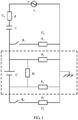
- FIG. 1 is a schematic diagram of an insulation resistance detection circuit of an active injected battery.
- an equation is constructed by injecting an alternating-current signal, to calculate an insulation resistance parallel value and determine whether an insulation failure occurs, and an insulation resistance value is calculated through a connection to a direct current resistance network.
- a part within a dashed-line box is equivalent to a to-be-tested battery, and U s represents an injected alternating-current power source.
- the equation is constructed by injecting the alternating-current signal, to calculate the insulation resistance parallel value and determine whether an insulation failure occurs, and the insulation resistance value is calculated through the connection to the direct current resistance network. As shown in FIG.
- the equation is constructed by injecting the alternating-current signal, to calculate the insulation resistance parallel value and determine whether an insulation failure occurs, and the insulation resistance value is calculated through the connection to the direct current resistance network.
- the part within the dashed-line box is equivalent to the to-be-tested battery, U s represents the injected alternating-current power source, R represents a measured resistor, C represents an isolation capacitor, and R 1 and R 2 are connected resistors for insulation resistance calculation.
- the "connected resistors" R 1 and R 2 are disconnected, and an alternating-current signal source is turned on.
- a parallel resistance value R pn may be obtained through calculation by measuring a voltage at two ends of the "measured resistor", and R pn is compared with a specified threshold R th to determine whether an insulation resistance failure occurs. If it is determined that an insulation resistance failure occurs, insulation resistance values R p and R n are calculated, where R p and R n are calculated in the following manner: obtaining a voltage equation related to R p and R n by closing the "connected resistors" R 1 and R 2 , and calculating the values R p and R n based on the parallel value R pn of R p and R n that is obtained in the foregoing second step.
- a capacitance value of the capacitor C needs to be known to calculate the insulation resistance parallel value of the battery.
- precision of the capacitance value of the capacitor actually is low, and a deviation of the capacitance value affects insulation resistance measurement precision.
- impact of insulation resistance parasitic capacitance is not considered in the foregoing solution, but actually existing parasitic capacitance affects precision of active injection method-based detection. As a result, insulation resistance detection precision for the battery is low.
- Embodiments of this application provide an insulation resistance detection circuit, detection method, and detection apparatus, to reduce impact of low precision of an actual capacitance value of a capacitor and a deviation of the capacitance value on insulation resistance measurement precision and reduce impact of actual existing parasitic capacitance on active injection method-based detection, thereby improving insulation resistance detection precision for a battery.
- a first aspect of the embodiments of this application provides an insulation resistance detection circuit, including:
- the resonant cavity is added to an active test circuit.
- the resonant cavity includes an inductor and a capacitor.
- an equation is constructed by considering impact of parasitic capacitance of the to-be-detected battery, to effectively reduce impact of the capacitor and the parasitic capacitance on insulation resistance detection precision for the to-be-detected battery, thereby improving the insulation resistance detection precision for the to-be-detected battery.
- the insulation resistance detection circuit further includes:
- the insulation resistance detection circuit further includes a fifth resistor and a third switch, where the fifth resistor is connected between the alternating-current signal source and the resonant cavity in series, and the third switch is connected to two ends of the fifth resistor in parallel.
- the fifth resistor may be connected between the first resistor and the alternating-current signal source in series, or may be connected between the first resistor and the resonant cavity in series. This is not limited in this solution.
- the resonant cavity includes a capacitor and an inductor that are connected in series.
- a second aspect of the embodiments of this application provides an insulation resistance detection circuit, including:
- the resonant cavity is added to an active test circuit.
- the resonant cavity includes an inductor and a capacitor.
- an equation is constructed by considering impact of parasitic capacitance of the to-be-detected battery, to effectively reduce impact of the capacitor and the parasitic capacitance on insulation resistance detection precision for the to-be-detected battery, thereby improving the insulation resistance detection precision for the to-be-detected battery.
- the insulation resistance detection circuit further includes:
- the insulation resistance detection circuit further includes a fifth resistor and a third switch, where the fifth resistor is connected between the alternating-current signal source and the resonant cavity in series, and the third switch is connected to two ends of the fifth resistor in parallel.
- the resonant cavity includes a capacitor and an inductor that are connected in series.
- a third aspect of the embodiments of this application provides an insulation resistance detection method, applied to the insulation resistance detection circuit provided in any one of the implementations of the first aspect or the second aspect; and the method includes:
- the method further includes: determining, based on the insulation resistance parallel value, whether an insulation failure occurs on the to-be-detected battery.
- the determining, based on the insulation resistance parallel value, whether an insulation failure occurs on the to-be-detected battery includes:
- controlling the alternating-current signal source to provide an alternating-current signal, and detecting a voltage of the first resistor includes:
- the obtaining a positive electrode insulation resistance and a negative electrode insulation resistance of the to-be-detected battery includes:
- the determining, based on the positive electrode insulation resistance and the negative electrode insulation resistance, whether an insulation failure occurs on the to-be-detected battery includes:
- a fourth aspect of the embodiments of this application provides an insulation resistance detection apparatus, applied to an insulation resistance detection apparatus that uses the insulation resistance detection circuit provided in the first aspect or the second aspect; and the apparatus includes:
- the processor is further configured to determine, based on the insulation resistance parallel value, whether an insulation failure occurs on the to-be-detected battery.
- the processor is specifically configured to:
- the processor is further specifically configured to:
- the processor is further specifically configured to:
- the processor is further configured to:
- a fifth aspect of the embodiments of this application provides a device, including at least one processor, a memory, and a communications interface.
- the at least one processor, the memory, and the communications interface are connected to each other; the memory stores a computer-executable instruction; and the at least one processor executes the computer-executable instruction stored in the memory, so that the device exchanges data with an insulation resistance detection circuit of the device through the communications interface to perform the insulation resistance detection method provided in the third aspect or the various implementations of the third aspect.
- a sixth aspect of the embodiments of this application provides a readable storage medium.
- the readable storage medium stores a computer-executable instruction.
- the device executes the computer-executable instruction, the device performs the insulation resistance detection method provided in the third aspect or the various implementations of the third aspect.
- a seventh aspect of the embodiments of this application provides a program product.
- the program product includes an executable instruction, and the executable instruction is stored in a readable storage medium.
- At least one processor of a device may read the executable instruction from the readable storage medium, and the at least one processor executes the executable instruction, so that the device implements the insulation resistance detection method provided in the third aspect or the various implementations of the third aspect.
- the insulation resistance detection circuit includes the alternating-current signal source, the resonant cavity, the first resistor, the second resistor, the third resistor, the fourth resistor, the first switch, and the second switch.
- the alternating-current signal source is sequentially connected to the first resistor, the resonant cavity, the first switch, the second resistor, and the third resistor in series to form a loop.
- the first resistor is connected to the positive electrode of the alternating-current signal source.
- the third resistor is connected to the negative electrode of the alternating-current signal source.
- the positive electrode of the to-be-detected battery is connected between the first switch and the resonant cavity, and the negative electrode of the alternating-current signal source is connected to the ground.
- One end of the second switch is connected to the negative electrode of the to-be-detected battery, the other end of the second switch is connected to the fourth resistor, and the other end of the fourth resistor is connected to the ground.
- the alternating-current signal source is controlled to provide the alternating-current signal
- the equation related to the insulation resistance parallel value and the parasitic capacitance parallel value of the to-be-detected battery is constructed based on the alternating-current signal and the voltage of the first resistor, and the insulation resistance parallel value of the to-be-detected battery is obtained.
- An error resulting from a precision difference of a capacitor is rectified inside the resonant cavity, and the parasitic capacitance of the to-be-detected battery is considered. This effectively improves insulation resistance detection precision.
- Embodiments of this application provide an active injected insulation resistance detection circuit and detection method. This can eliminate impact of a connected auxiliary resistor on an insulation status of a battery system, and eliminate impact of a capacitor C and insulation resistance parasitic capacitance in an active injection method on detection precision. In addition, this can also accurately determine an insulation failure and simplify a voltage measurement circuit.
- the following describes the technical solutions in the embodiments of this application by using several specific implementations.
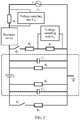
- FIG. 2 is a principle diagram of Embodiment 1 of an insulation resistance detection circuit according to embodiments of this application.
- the insulation resistance detection circuit includes an alternating-current signal source U s , a resonant cavity, a first resistor R r , a second resistor R 1 , a third resistor R 2 , a fourth resistor R 3 , a first switch K 1 , and a second switch K 2 .
- the alternating-current signal source U s is sequentially connected to the first resistor R r , the resonant cavity, the first switch K 1 , the second resistor R 1 , and the third resistor R 2 in series to form a loop.
- the first resistor R r is connected to a positive electrode of the alternating-current signal source U s
- the third resistor R 2 is connected to a negative electrode of the alternating-current signal source U s .
- a to-be-detected battery (a part within a dashed-line box is an equivalent circuit of the to-be-detected battery, and an entirety of the dashed-line box is the to-be-detected battery) is excluded from a structure of the detection circuit.
- a positive electrode of the to-be-detected battery is connected between the first switch K 1 and the resonant cavity, and the negative electrode of the alternating-current signal source U s is connected to ground.
- the positive electrode of the to-be-detected battery and the ground are parallel-connected to two sides of the first switch K 1 , the second resistor R 1 , and the third resistor R 2 that are sequentially connected in series.
- One end of the second switch K 2 is connected to a negative electrode of the to-be-detected battery, the other end of the second switch K 2 is connected to the fourth resistor R 3 , and the other end of the fourth resistor R 3 is connected to the ground.
- two ends of an entirety obtained by connecting the second switch K 2 to the fourth resistor R 3 in series is parallel-connected to two sides of the negative electrode of the to-be-detected battery and the ground.
- the detection circuit structure includes one alternating-current signal source U s and one resonant cavity.
- the resonant cavity includes an inductor, a capacitor, auxiliary resistors R r , R 1 , R 2 , and R 3 , and auxiliary switches K 1 and K 2 .
- a part within a dashed-line box represents an equivalent circuit of a power battery (a to-be-detected battery), and includes an ideal voltage source U, an insulation resistor R p and a parasitic capacitor C p between a positive electrode of the power battery and a reference ground, and an insulation resistor R n and a parasitic capacitor C n between a negative electrode of the power energy and the reference ground.
- the to-be-detected battery is equivalent to a power source that includes an ideal power source, a parasitic capacitor, and an insulation resistor.
- components connected between the positive/negative electrode of the to-be-detected battery and the ground may be alternatively exchanged.
- the negative electrode of the to-be-detected battery is connected between the first switch K 1 and the resonant cavity; the negative electrode of the alternating-current signal source U s is connected to the ground; one end of the second switch K 2 is connected to the positive electrode of the to-be-detected battery; the other end of the second switch K 2 is connected to the fourth resistor R 3 ; and the other end of the fourth resistor R 3 is connected to the ground.
- the negative electrode of the to-be-detected battery and the ground are parallel-connected to two sides of the first switch K 1 , the second resistor R 1 , and the third resistor R 2 that are sequentially connected in series, and an entirety obtained by connecting the second switch K 2 to the fourth resistor R 3 in series is parallel-connected to two sides of the positive electrode of the to-be-detected battery and the ground.
- the alternating-current signal source is configured to provide an alternating-current signal
- an equation related to an insulation resistance parallel value and a parasitic capacitance parallel value of the to-be-detected battery is constructed based on the alternating-current signal and a voltage of the first resistor, and the insulation resistance parallel value of the to-be-detected battery is obtained. Therefore, whether a failure occurs on the to-be-detected battery may be still determined based on the insulation resistance parallel value.
- the insulation resistance detection circuit further includes a first voltage sampling unit U m and a second voltage sampling unit U n .
- the first voltage sampling unit U m is connected to the first resistor R r in parallel, to detect a voltage at two ends of the first resistor R r .
- the second voltage sampling unit U n is connected to the third resistor R 2 in parallel, to detect a voltage at two ends of the third resistor R 2 .
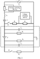
- FIG. 3 is a principle diagram of Embodiment 2 of an insulation resistance detection circuit according to embodiments of this application. As shown in FIG. 3 , other constituents are the same as those in the foregoing embodiment, and a resonant cavity in the detection circuit is specifically implemented as an inductor L r and a capacitor C r , in other words, the resonant cavity includes the capacitor C r and the inductor L r that are connected in series.
- FIG. 4 is a principle diagram of Embodiment 3 of an insulation resistance detection circuit according to embodiments of this application.
- a fifth resistor may be further connected between a resonant cavity and an alternating-current signal source U s in series, and a switch is connected to two ends of the fifth resistor in parallel.
- the insulation resistance detection circuit further includes the fifth resistor R r1 and a third switch K r ; and the fifth resistor R r1 is connected between the alternating-current signal source U s and the resonant cavity in series, and the third switch K r is connected to the fifth resistor R r1 in parallel.
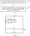
- FIG. 5 is a flowchart of an insulation resistance detection method according to an embodiment of this application. As shown in FIG. 5 , the method is applied to a device or an apparatus that can perform operation processing. A to-be-detected battery is connected to the foregoing detection circuit to collect data for calculation and analysis. Specifically, the insulation resistance detection method includes the following steps.
- S101 Control the alternating-current signal source to provide an alternating-current signal, and detect a voltage of a first resistor.
- S102 Construct an equation based on the alternating-current signal and the voltage of the first resistor, and obtain an insulation resistance parallel value and a parasitic capacitance parallel value of the to-be-detected battery.
- an equation related to the parasitic capacitance parallel value and the insulation resistance parallel value of the to-be-detected battery is constructed for calculation by detecting voltage values of different auxiliary resistors and with reference to input of the alternating-current signal source, to obtain the insulation resistance parallel value.
- whether an insulation failure occurs on the to-be-detected battery may be further determined based on the insulation resistance parallel value, and this may be specifically implemented in the following manner:
- an insulation resistance detection procedure includes the following steps.
- Step 1 Inject an alternating-current signal U s , and calculate an insulation resistance parallel value R b and a parasitic capacitance parallel value C b .
- Step 2 Determine an insulation status of a power battery based on the insulation resistance parallel value R b and a preset resistance threshold (also referred to as a threshold resistance) R th , and take corresponding measures.
- a preset resistance threshold also referred to as a threshold resistance
- FIG. 6 is an equivalent circuit diagram of the frequency disturbance method according to an embodiment of this application.
- R b is a parallel value of reference ground insulation resistance values R p and R n relative to a positive electrode and a negative electrode of the power battery
- C b is a parallel value of reference ground parasitic capacitance values C p and C n relative to the positive electrode and the negative electrode of the power battery.
- the inductor L r and the capacitor C r are in a resonant state or at a resonant point nearby at a frequency when the alternating-current signal is injected, an equivalent impedance of the resonant cavity may be approximately zero. Therefore, values of the capacitor C r and the inductor L r do not affect insulation resistance calculation. In addition, the capacitor C r isolates a direct-current high voltage of the power battery, and an active detection circuit does not affect insulation resistance of the power battery.
- a first switch and a second switch are controlled to be disconnected; the alternating-current signal source is controlled to inject a sine signal with a frequency ⁇ 1 and an amplitude value U s , and it is detected that a voltage at two ends of the first resistor is U m1 ; and the alternating-current signal source is controlled to inject a sine signal with a frequency ⁇ 2 and an amplitude value U s , and it is detected that a voltage at the two ends of the first resistor is U m2 .
- the alternating-current signal source U s injects the sine signal with the frequency ⁇ 2 and the amplitude value U s , and the voltage U m2 at the two ends of the first resistor (an auxiliary resistor) R r is measured to obtain the following equation (2):
- U m 2 R r ⁇ 2 C b R b 2 + 1 2 ⁇ 2 C b R b R r 2 + R b + R r 2 U s
- R r represents a resistance value of the first resistor, ⁇ 1 ⁇ 2
- the insulation resistance parallel value R b and the parasitic capacitance parallel value C b may be obtained through calculation by combining the equation (1) and the equation (2).
- an insulation status of the power battery may be determined based on the insulation resistance parallel value R b and the resistance threshold (the preset threshold resistance) R th , and corresponding measures are taken.
- the insulation resistance parallel value R b is compared with R th , and the insulation status of the power battery is divided into three states, so that accurate determining can be implemented.
- the resistance threshold or the threshold resistance R th is set according to a related technology standard and a voltage value of the power battery.
- ISO / DIS 6469-1 2000 Electric Road Vehicles-Safety Specifications - Part 1: On-Board Electrical Energy Storage
- a value of an insulation resistance parameter needs to be greater than 500 ⁇ /V as required in this standard. Therefore, the reference ground insulation resistance values R p and R n relative to a positive electrode and a negative electrode of the electrical vehicle battery pack need to be greater than 250 k ⁇ . Therefore, the threshold resistance R th is set to 250 k ⁇ .
- FIG. 7 is an equivalent circuit diagram of the improved balancing bridge method according to an embodiment of this application. As shown in FIG. 7 , only one voltage measurement unit U n is required in comparison with a conventional balancing bridge method.
- a specific implementation process includes the following steps:
- the insulation resistance values R p and R n may be obtained through calculation by combining the equation (5) and the equation (6). Compared with the conventional balancing bridge method, this method reduces one voltage detection unit by increasing resistance disturbance once, thereby simplifying a voltage measurement circuit.
- FIG. 8 is an equivalent circuit diagram of the resistance disturbance method according to an embodiment of this application.
- R b is a parallel value of reference ground insulation resistance values R p and R n relative to a positive electrode and a negative electrode of the power battery
- C b is a parallel value of reference ground parasitic capacitance values C p and C n relative to the positive electrode and the negative electrode of the power battery.
- an auxiliary resistor and an auxiliary switch namely, a fifth resistor R r1 and a third switch K r , are additionally added on the basis of the circuit diagram in the frequency disturbance method.
- An insulation resistance detection procedure includes the following steps:
- the alternating-current signal source U s is injected, and the insulation resistance parallel value and the parasitic capacitance parallel value may be alternatively calculated by using the amplitude phase method.
- An additional circuit is not required in the amplitude phase method, and an equivalent circuit in the amplitude phase method is the same as that in the frequency disturbance method, as shown in FIG. 6 .
- the amplitude phase method includes the following steps:
- FIG. 9 is a schematic structural diagram of an insulation resistance detection apparatus according to an embodiment of this application. As shown in FIG. 9 , the insulation resistance detection apparatus is applied to an apparatus (for example, a computer or another terminal device) used for insulation resistance detection by using the insulation resistance detection circuit provided in the foregoing solution.
- an apparatus for example, a computer or another terminal device
- the insulation resistance detection apparatus includes a processor 11 and an insulation resistance detection circuit 12 provided in the foregoing embodiment.
- the processor 11 is electrically connected to the insulation resistance detection circuit.
- the to-be-detected battery is connected to the insulation resistance detection circuit in the manner shown in the foregoing principle diagram.
- the processor 11 is configured to: control to execute the following solution, and collect data for calculation and analysis. Details are as follows:
- the processor 11 is configured to: control the alternating-current signal source to provide an alternating-current signal, and detect a voltage of a first resistor.
- the processor is further configured to: construct an equation based on the alternating-current signal and the voltage of the first resistor, and obtain an insulation resistance parallel value and a parasitic capacitance parallel value of the to-be-detected battery.
- the processor 11 is further configured to determine, based on the insulation resistance parallel value, whether an insulation failure occurs on the to-be-detected battery.
- the processor 11 is specifically configured to:
- processor 11 is further specifically configured to:
- processor 11 is further specifically configured to:
- the processor 11 is further configured to:
- the insulation resistance detection apparatus provided in this embodiment is configured to execute the technical solution of the foregoing detection method.
- An implementation principle and a technical solution of the insulation resistance detection apparatus are similar to those of the detection method. Details are not described herein again.
- An embodiment of this application further provides a device, including at least one processor, a memory, and a communications interface.
- the at least one processor, the memory, and the communications interface are connected to each other; the memory stores a computer-executable instruction; and the at least one processor executes the computer-executable instruction stored in the memory, so that the device exchanges data with an insulation resistance detection circuit of the device through the communications interface to perform the insulation resistance detection method provided in the foregoing various implementations.
- An embodiment of this application further provides a readable storage medium.
- the readable storage medium stores a computer-executable instruction.
- the device executes the computer-executable instruction, the device performs the insulation resistance detection method provided in the foregoing various implementations.
- An embodiment of this application further provides a program product.
- the program product includes an executable instruction, and the executable instruction is stored in a readable storage medium.
- At least one processor of a device may read the executable instruction from the readable storage medium, and the at least one processor executes the executable instruction, so that the device implements the insulation resistance detection method provided in the foregoing various implementations.
- the processor may be a central processing unit (CPU for short), or may be another general-purpose processor, a digital signal processor (DSP for short), an application-specific integrated circuit (ASIC for short), or the like.
- the general-purpose processor may be a microprocessor or the processor may be any conventional processor, or the like.
- the steps of the method disclosed with reference to the embodiments of this application may be directly performed by a hardware processor, or may be performed by using a combination of hardware in the processor and a software module.
Landscapes
- Physics & Mathematics (AREA)
- General Physics & Mathematics (AREA)
- Testing Of Short-Circuits, Discontinuities, Leakage, Or Incorrect Line Connections (AREA)
- Measurement Of Resistance Or Impedance (AREA)
- Secondary Cells (AREA)
Description
- Embodiments of this application relate to circuit and electronic technologies, and in particular, to an insulation resistance detection circuit, detection method, and detection apparatus.
- With rapid development of new energy vehicles, electric vehicles attach ever-increasing attention. As a power source of an electric vehicle, a high-voltage power battery pack has a quite high voltage class, and insulation performance of the high-voltage power battery pack directly affects safe operation of the electric vehicle. Quickly and accurately detecting an insulation status of the battery pack for a chassis of the vehicle and timely performing troubleshooting are basic conditions for safe operation of the electric vehicle. This is of great significance for ensuring passenger safety, normal operation of electric equipment, and safe operation of the vehicle.
- The document, WEI YANG ET AL: "An Active Detection Method for Insulation performance of high voltage power battery pack", COMPUTING TECHNOLOGY AND AUTOMATION, vol. 34, no. 3, 1 September 2015 (2015-09-01), pages 55-59, discloses a circuit for detecting the insulation resistance of a battery. An alternating-current source provides an ac signal to be injected via an arrangement of resistors and switches into the battery under test.
-
FIG. 1 is a schematic diagram of an insulation resistance detection circuit of an active injected battery. As shown inFIG. 1 , an equation is constructed by injecting an alternating-current signal, to calculate an insulation resistance parallel value and determine whether an insulation failure occurs, and an insulation resistance value is calculated through a connection to a direct current resistance network. A part within a dashed-line box is equivalent to a to-be-tested battery, and Us represents an injected alternating-current power source. In this technology, the equation is constructed by injecting the alternating-current signal, to calculate the insulation resistance parallel value and determine whether an insulation failure occurs, and the insulation resistance value is calculated through the connection to the direct current resistance network. As shown inFIG. 1 , the equation is constructed by injecting the alternating-current signal, to calculate the insulation resistance parallel value and determine whether an insulation failure occurs, and the insulation resistance value is calculated through the connection to the direct current resistance network. The part within the dashed-line box is equivalent to the to-be-tested battery, Us represents the injected alternating-current power source, R represents a measured resistor, C represents an isolation capacitor, and R1 and R2 are connected resistors for insulation resistance calculation. The "connected resistors" R1 and R2 are disconnected, and an alternating-current signal source is turned on. A parallel resistance value Rpn may be obtained through calculation by measuring a voltage at two ends of the "measured resistor", and Rpn is compared with a specified threshold Rth to determine whether an insulation resistance failure occurs. If it is determined that an insulation resistance failure occurs, insulation resistance values Rp and Rn are calculated, where Rp and Rn are calculated in the following manner: obtaining a voltage equation related to Rp and Rn by closing the "connected resistors" R1 and R2, and calculating the values Rp and Rn based on the parallel value Rpn of Rp and Rn that is obtained in the foregoing second step. - However, in the foregoing solution, a capacitance value of the capacitor C needs to be known to calculate the insulation resistance parallel value of the battery. However, precision of the capacitance value of the capacitor actually is low, and a deviation of the capacitance value affects insulation resistance measurement precision. In addition, impact of insulation resistance parasitic capacitance is not considered in the foregoing solution, but actually existing parasitic capacitance affects precision of active injection method-based detection. As a result, insulation resistance detection precision for the battery is low.
- Embodiments of this application provide an insulation resistance detection circuit, detection method, and detection apparatus, to reduce impact of low precision of an actual capacitance value of a capacitor and a deviation of the capacitance value on insulation resistance measurement precision and reduce impact of actual existing parasitic capacitance on active injection method-based detection, thereby improving insulation resistance detection precision for a battery.
- A first aspect of the embodiments of this application provides an insulation resistance detection circuit, including:
- an alternating-current signal source, a resonant cavity, a first resistor, a second resistor, a third resistor, a fourth resistor, a first switch, and a second switch, where
- the alternating-current signal source is sequentially connected to the first resistor, the resonant cavity, the first switch, the second resistor, and the third resistor in series to form a loop, where the first resistor is connected to a positive electrode of the alternating-current signal source, and the third resistor is connected to a negative electrode of the alternating-current signal source;
- a positive electrode of a to-be-detected battery is connected between the first switch and the resonant cavity, and the negative electrode of the alternating-current signal source is connected to ground;
- one end of the second switch is connected to a negative electrode of the to-be-detected battery, the other end of the second switch is connected to the fourth resistor, and the other end of the fourth resistor is connected to the ground; and
- when the to-be-detected battery is detected, the alternating-current signal source is configured to provide an alternating-current signal.
- In this solution, the resonant cavity is added to an active test circuit. Generally, the resonant cavity includes an inductor and a capacitor. In addition, in a detection process, an equation is constructed by considering impact of parasitic capacitance of the to-be-detected battery, to effectively reduce impact of the capacitor and the parasitic capacitance on insulation resistance detection precision for the to-be-detected battery, thereby improving the insulation resistance detection precision for the to-be-detected battery.
- In specific implementation, the insulation resistance detection circuit further includes:
- a first voltage sampling unit and a second voltage sampling unit, where
- the first voltage sampling unit is connected to the first resistor in parallel, to detect a voltage at two ends of the first resistor; and
- the second voltage sampling unit is connected to the third resistor in parallel, to detect a voltage at two ends of the third resistor.
- In specific implementation, the insulation resistance detection circuit further includes a fifth resistor and a third switch, where
the fifth resistor is connected between the alternating-current signal source and the resonant cavity in series, and the third switch is connected to two ends of the fifth resistor in parallel. - In this solution, the fifth resistor may be connected between the first resistor and the alternating-current signal source in series, or may be connected between the first resistor and the resonant cavity in series. This is not limited in this solution.
- In specific implementation, the resonant cavity includes a capacitor and an inductor that are connected in series.
- A second aspect of the embodiments of this application provides an insulation resistance detection circuit, including:
- an alternating-current signal source, a resonant cavity, a first resistor, a second resistor, a third resistor, a fourth resistor, a first switch, and a second switch, where
- the alternating-current signal source is sequentially connected to the first resistor, the resonant cavity, the first switch, the second resistor, and the third resistor in series to form a loop, where the first resistor is connected to a positive electrode of the alternating-current signal source, and the third resistor is connected to a negative electrode of the alternating-current signal source;
- a negative electrode of a to-be-detected battery is connected between the first switch and the resonant cavity, and the negative electrode of the alternating-current signal source is connected to ground;
- one end of the second switch is connected to a positive electrode of the to-be-detected battery, the other end of the second switch is connected to the fourth resistor, and the other end of the fourth resistor is connected to the ground; and
- when the to-be-detected battery is detected, the alternating-current signal source is configured to provide an alternating-current signal.
- In this solution, the resonant cavity is added to an active test circuit. Generally, the resonant cavity includes an inductor and a capacitor. In addition, in a detection process, an equation is constructed by considering impact of parasitic capacitance of the to-be-detected battery, to effectively reduce impact of the capacitor and the parasitic capacitance on insulation resistance detection precision for the to-be-detected battery, thereby improving the insulation resistance detection precision for the to-be-detected battery.
- In specific implementation, the insulation resistance detection circuit further includes:
- a first voltage sampling unit and a second voltage sampling unit, where
- the first voltage sampling unit is connected to the first resistor in parallel, to detect a voltage at two ends of the first resistor; and
- the second voltage sampling unit is connected to the third resistor in parallel, to detect a voltage at two ends of the third resistor.
- In specific implementation, the insulation resistance detection circuit further includes a fifth resistor and a third switch, where
the fifth resistor is connected between the alternating-current signal source and the resonant cavity in series, and the third switch is connected to two ends of the fifth resistor in parallel. - In specific implementation, the resonant cavity includes a capacitor and an inductor that are connected in series.
- A third aspect of the embodiments of this application provides an insulation resistance detection method, applied to the insulation resistance detection circuit provided in any one of the implementations of the first aspect or the second aspect; and the method includes:
- controlling the alternating-current signal source to provide an alternating-current signal, and detecting a voltage of a first resistor; and
- constructing an equation based on the alternating-current signal and the voltage of the first resistor, and obtaining an insulation resistance parallel value and a parasitic capacitance parallel value of a to-be-detected battery.
- In specific implementation, the method further includes:
determining, based on the insulation resistance parallel value, whether an insulation failure occurs on the to-be-detected battery. - In specific implementation, the determining, based on the insulation resistance parallel value, whether an insulation failure occurs on the to-be-detected battery includes:
- if the insulation resistance parallel value is greater than a preset resistance threshold, determining that no insulation failure occurs on the to-be-detected battery;
- if the insulation resistance parallel value is less than the resistance threshold and greater than half of the resistance threshold, obtaining a positive electrode insulation resistance and a negative electrode insulation resistance of the to-be-detected battery, and determining, based on the positive electrode insulation resistance and the negative electrode insulation resistance, whether an insulation failure occurs on the to-be-detected battery; or
- if the insulation resistance parallel value is less than half of the resistance threshold, determining that an insulation failure occurs on the to-be-detected battery.
- In specific implementation, the controlling the alternating-current signal source to provide an alternating-current signal, and detecting a voltage of the first resistor includes:
- controlling to disconnect a first switch and a second switch;
- controlling the alternating-current signal source to inject a sine signal with a frequency ω1 and an amplitude value Us, and detecting that a voltage at two ends of the first resistor is Um1; and
- controlling the alternating-current signal source to inject a sine signal with a frequency ω2 and an amplitude value Us, and detecting that a voltage at the two ends of the first resistor is Um2; and
- the constructing an equation based on the alternating-current signal and the voltage of the first resistor, and obtaining an insulation resistance parallel value and a parasitic capacitance parallel value of a to-be-detected battery includes:
- constructing an equation (1) based on Us and Um1:

- constructing an equation (2) based on Us and Um2:

- obtaining the insulation resistance parallel value Rb and the parasitic capacitance parallel value Cb of the to-be-detected battery through calculation according to the equation (1) and the equation (2), where Rr represents a resistance value of the first resistor.
- constructing an equation (1) based on Us and Um1:
- In specific implementation, the obtaining a positive electrode insulation resistance and a negative electrode insulation resistance of the to-be-detected battery includes:
- controlling to turn off the alternating-current signal source;
- closing a first switch, obtaining a voltage Un1 of a third resistor through detection, and constructing an equation (3) based on a voltage U of the to-be-detected battery and the voltage Un1 of the third resistor:

- closing the first switch and a second switch, obtaining a voltage Un2 of the third resistor through detection, and constructing an equation (4) based on the voltage U of the to-be-detected battery and the voltage Un1 of the third resistor:

- obtaining the positive electrode insulation resistance Rp and the negative electrode insulation resistance Rn of the to-be-detected battery through calculation according to the equation (3), the equation (4), and an equation (5)

- R1 represents a resistance value of the second resistor, R2 represents a resistance value of the third resistor, R3 represents a resistance value of a fourth resistor, and Rb represents the insulation resistance parallel value of the to-be-detected battery.
- In specific implementation, the determining, based on the positive electrode insulation resistance and the negative electrode insulation resistance, whether an insulation failure occurs on the to-be-detected battery includes:
- if both the positive electrode insulation resistance and the negative electrode insulation resistance are greater than the resistance threshold, determining that no insulation failure occurs on the to-be-detected battery; or
- if neither the positive electrode insulation resistance nor the negative electrode insulation resistance is greater than the resistance threshold, determining that an insulation failure occurs on the to-be-detected battery.
- A fourth aspect of the embodiments of this application provides an insulation resistance detection apparatus, applied to an insulation resistance detection apparatus that uses the insulation resistance detection circuit provided in the first aspect or the second aspect; and the apparatus includes:
- a processor, configured to: control the alternating-current signal source to provide an alternating-current signal, and detect a voltage of a first resistor, where
- the processor is further configured to: construct an equation based on the alternating-current signal and the voltage of the first resistor, and obtain an insulation resistance parallel value and a parasitic capacitance parallel value of a to-be-detected battery.
- In specific implementation, the processor is further configured to determine, based on the insulation resistance parallel value, whether an insulation failure occurs on the to-be-detected battery.
- In specific implementation, the processor is specifically configured to:
- if the insulation resistance parallel value is greater than a preset resistance threshold, determine that no insulation failure occurs on the to-be-detected battery;
- if the insulation resistance parallel value is less than the resistance threshold and greater than half of the resistance threshold, obtain a positive electrode insulation resistance and a negative electrode insulation resistance of the to-be-detected battery, and determine, based on the positive electrode insulation resistance and the negative electrode insulation resistance, whether an insulation failure occurs on the to-be-detected battery; or
- if the insulation resistance parallel value is less than half of the resistance threshold, determine that an insulation failure occurs on the to-be-detected battery.
- In specific implementation, the processor is further specifically configured to:
- control to disconnect a first switch and a second switch;
- control the alternating-current signal source to inject a sine signal with a frequency ω1 and an amplitude value Us, and detect that a voltage at two ends of the first resistor is Um1; and
- control the alternating-current signal source to inject a sine signal with a frequency ω2 and an amplitude value Us, and detect that a voltage at the two ends of the first resistor is Um2; and
- the constructing an equation based on the alternating-current signal and the voltage of the first resistor, and obtaining an insulation resistance parallel value and a parasitic capacitance parallel value of a to-be-detected battery includes:
- constructing an equation (1) based on Us and Um1:

- constructing an equation (2) based on Us and Um2:

- obtaining the insulation resistance parallel value Rb and the parasitic capacitance parallel value Cb of the to-be-detected battery through calculation according to the equation (1) and the equation (2), where Rr represents a resistance value of the first resistor.
- constructing an equation (1) based on Us and Um1:
- In specific implementation, the processor is further specifically configured to:
- control to turn off the alternating-current signal source;
- close a first switch, obtain a voltage Un1 of a third resistor through detection, and construct an equation (3) based on a voltage U of the to-be-detected battery and the voltage Un1 of the third resistor:

- close the first switch and a second switch, obtain a voltage Un2 of the third resistor through detection, and construct an equation (4) based on the voltage U of the to-be-detected battery and the voltage Un1 of the third resistor:

- obtain the positive electrode insulation resistance Rp and the negative electrode insulation resistance Rn of the to-be-detected battery through calculation according to the equation (3), the equation (4), and an equation (5)

- R1 represents a resistance value of the second resistor, R2 represents a resistance value of the third resistor, R3 represents a resistance value of a fourth resistor, and Rb represents the insulation resistance parallel value of the to-be-detected battery.
- In specific implementation, the processor is further configured to:
- if both the positive electrode insulation resistance and the negative electrode insulation resistance are greater than the resistance threshold, determine that no insulation failure occurs on the to-be-detected battery; or
- if neither the positive electrode insulation resistance nor the negative electrode insulation resistance is greater than the resistance threshold, determine that an insulation failure occurs on the to-be-detected battery.
- A fifth aspect of the embodiments of this application provides a device, including at least one processor, a memory, and a communications interface. The at least one processor, the memory, and the communications interface are connected to each other; the memory stores a computer-executable instruction; and the at least one processor executes the computer-executable instruction stored in the memory, so that the device exchanges data with an insulation resistance detection circuit of the device through the communications interface to perform the insulation resistance detection method provided in the third aspect or the various implementations of the third aspect.
- A sixth aspect of the embodiments of this application provides a readable storage medium. The readable storage medium stores a computer-executable instruction. When at least one processor of a device executes the computer-executable instruction, the device performs the insulation resistance detection method provided in the third aspect or the various implementations of the third aspect.
- A seventh aspect of the embodiments of this application provides a program product. The program product includes an executable instruction, and the executable instruction is stored in a readable storage medium. At least one processor of a device may read the executable instruction from the readable storage medium, and the at least one processor executes the executable instruction, so that the device implements the insulation resistance detection method provided in the third aspect or the various implementations of the third aspect.
- According to the insulation resistance detection circuit, detection method, and detection apparatus provided in the embodiments of this application, parasitic capacitance and insulation resistance of the to-be-detected battery are detected by using an active injected detection circuit. The insulation resistance detection circuit includes the alternating-current signal source, the resonant cavity, the first resistor, the second resistor, the third resistor, the fourth resistor, the first switch, and the second switch. The alternating-current signal source is sequentially connected to the first resistor, the resonant cavity, the first switch, the second resistor, and the third resistor in series to form a loop. The first resistor is connected to the positive electrode of the alternating-current signal source. The third resistor is connected to the negative electrode of the alternating-current signal source. The positive electrode of the to-be-detected battery is connected between the first switch and the resonant cavity, and the negative electrode of the alternating-current signal source is connected to the ground. One end of the second switch is connected to the negative electrode of the to-be-detected battery, the other end of the second switch is connected to the fourth resistor, and the other end of the fourth resistor is connected to the ground. When the to-be-detected battery is detected, the alternating-current signal source is controlled to provide the alternating-current signal, the equation related to the insulation resistance parallel value and the parasitic capacitance parallel value of the to-be-detected battery is constructed based on the alternating-current signal and the voltage of the first resistor, and the insulation resistance parallel value of the to-be-detected battery is obtained. An error resulting from a precision difference of a capacitor is rectified inside the resonant cavity, and the parasitic capacitance of the to-be-detected battery is considered. This effectively improves insulation resistance detection precision.
-
-
FIG. 1 is a schematic diagram of an insulation resistance detection circuit of an active injected battery; -
FIG. 2 is a principle diagram ofEmbodiment 1 of an insulation resistance detection circuit according to embodiments of this application; -
FIG. 3 is a principle diagram of Embodiment 2 of an insulation resistance detection circuit according to embodiments of this application; -
FIG. 4 is a principle diagram of Embodiment 3 of an insulation resistance detection circuit according to embodiments of this application; -
FIG. 5 is a flowchart of an insulation resistance detection method according to an embodiment of this application; -
FIG. 6 is an equivalent circuit diagram of a frequency disturbance method according to an embodiment of this application; -
FIG. 7 is an equivalent circuit diagram of an improved balancing bridge method according to an embodiment of this application; -
FIG. 8 is an equivalent circuit diagram of a resistance disturbance method according to an embodiment of this application; and -
FIG. 9 is a schematic structural diagram of an insulation resistance detection apparatus according to an embodiment of this application. - Embodiments of this application provide an active injected insulation resistance detection circuit and detection method. This can eliminate impact of a connected auxiliary resistor on an insulation status of a battery system, and eliminate impact of a capacitor C and insulation resistance parasitic capacitance in an active injection method on detection precision. In addition, this can also accurately determine an insulation failure and simplify a voltage measurement circuit. The following describes the technical solutions in the embodiments of this application by using several specific implementations.
-
FIG. 2 is a principle diagram ofEmbodiment 1 of an insulation resistance detection circuit according to embodiments of this application. As shown inFIG. 2 , the insulation resistance detection circuit includes an alternating-current signal source Us, a resonant cavity, a first resistor Rr, a second resistor R1, a third resistor R2, a fourth resistor R3, a first switch K1, and a second switch K2. - The alternating-current signal source Us is sequentially connected to the first resistor Rr, the resonant cavity, the first switch K1, the second resistor R1, and the third resistor R2 in series to form a loop. The first resistor Rr is connected to a positive electrode of the alternating-current signal source Us, and the third resistor R2 is connected to a negative electrode of the alternating-current signal source Us.
- In this solution, a to-be-detected battery (a part within a dashed-line box is an equivalent circuit of the to-be-detected battery, and an entirety of the dashed-line box is the to-be-detected battery) is excluded from a structure of the detection circuit.
- A positive electrode of the to-be-detected battery is connected between the first switch K1 and the resonant cavity, and the negative electrode of the alternating-current signal source Us is connected to ground. In other words, the positive electrode of the to-be-detected battery and the ground are parallel-connected to two sides of the first switch K1, the second resistor R1, and the third resistor R2 that are sequentially connected in series.
- One end of the second switch K2 is connected to a negative electrode of the to-be-detected battery, the other end of the second switch K2 is connected to the fourth resistor R3, and the other end of the fourth resistor R3 is connected to the ground. In other words, two ends of an entirety obtained by connecting the second switch K2 to the fourth resistor R3 in series is parallel-connected to two sides of the negative electrode of the to-be-detected battery and the ground.
- In the foregoing solution, for details, refer to the principle diagram in
FIG. 1 . The detection circuit structure includes one alternating-current signal source Us and one resonant cavity. In an implementation, the resonant cavity includes an inductor, a capacitor, auxiliary resistors Rr, R1, R2, and R3, and auxiliary switches K1 and K2. A part within a dashed-line box represents an equivalent circuit of a power battery (a to-be-detected battery), and includes an ideal voltage source U, an insulation resistor Rp and a parasitic capacitor Cp between a positive electrode of the power battery and a reference ground, and an insulation resistor Rn and a parasitic capacitor Cn between a negative electrode of the power energy and the reference ground. In other words, the to-be-detected battery is equivalent to a power source that includes an ideal power source, a parasitic capacitor, and an insulation resistor. - Optionally, in specific application of the circuit, components connected between the positive/negative electrode of the to-be-detected battery and the ground may be alternatively exchanged. The negative electrode of the to-be-detected battery is connected between the first switch K1 and the resonant cavity; the negative electrode of the alternating-current signal source Us is connected to the ground; one end of the second switch K2 is connected to the positive electrode of the to-be-detected battery; the other end of the second switch K2 is connected to the fourth resistor R3; and the other end of the fourth resistor R3 is connected to the ground. In other words, the negative electrode of the to-be-detected battery and the ground are parallel-connected to two sides of the first switch K1, the second resistor R1, and the third resistor R2 that are sequentially connected in series, and an entirety obtained by connecting the second switch K2 to the fourth resistor R3 in series is parallel-connected to two sides of the positive electrode of the to-be-detected battery and the ground.
- When the to-be-detected battery is detected, the alternating-current signal source is configured to provide an alternating-current signal, an equation related to an insulation resistance parallel value and a parasitic capacitance parallel value of the to-be-detected battery is constructed based on the alternating-current signal and a voltage of the first resistor, and the insulation resistance parallel value of the to-be-detected battery is obtained. Therefore, whether a failure occurs on the to-be-detected battery may be still determined based on the insulation resistance parallel value.
- Further, to detect voltage values of the first resistor Rr and the third resistor R2, the insulation resistance detection circuit further includes a first voltage sampling unit Um and a second voltage sampling unit Un. The first voltage sampling unit Um is connected to the first resistor Rr in parallel, to detect a voltage at two ends of the first resistor Rr. The second voltage sampling unit Un is connected to the third resistor R2 in parallel, to detect a voltage at two ends of the third resistor R2.
-
FIG. 3 is a principle diagram of Embodiment 2 of an insulation resistance detection circuit according to embodiments of this application. As shown inFIG. 3 , other constituents are the same as those in the foregoing embodiment, and a resonant cavity in the detection circuit is specifically implemented as an inductor Lr and a capacitor Cr, in other words, the resonant cavity includes the capacitor Cr and the inductor Lr that are connected in series. -
FIG. 4 is a principle diagram of Embodiment 3 of an insulation resistance detection circuit according to embodiments of this application. As shown inFIG. 4 , in specific implementation of the insulation resistance detection circuit, a fifth resistor may be further connected between a resonant cavity and an alternating-current signal source Us in series, and a switch is connected to two ends of the fifth resistor in parallel. In other words, the insulation resistance detection circuit further includes the fifth resistor Rr1 and a third switch Kr; and the fifth resistor Rr1 is connected between the alternating-current signal source Us and the resonant cavity in series, and the third switch Kr is connected to the fifth resistor Rr1 in parallel. - On the basis of the several insulation resistance detection circuits, the following describes specific implementation methods for detecting insulation resistance performance.
-
FIG. 5 is a flowchart of an insulation resistance detection method according to an embodiment of this application. As shown inFIG. 5 , the method is applied to a device or an apparatus that can perform operation processing. A to-be-detected battery is connected to the foregoing detection circuit to collect data for calculation and analysis. Specifically, the insulation resistance detection method includes the following steps. - S101: Control the alternating-current signal source to provide an alternating-current signal, and detect a voltage of a first resistor.
- S102: Construct an equation based on the alternating-current signal and the voltage of the first resistor, and obtain an insulation resistance parallel value and a parasitic capacitance parallel value of the to-be-detected battery.
- In the foregoing steps, an equation related to the parasitic capacitance parallel value and the insulation resistance parallel value of the to-be-detected battery is constructed for calculation by detecting voltage values of different auxiliary resistors and with reference to input of the alternating-current signal source, to obtain the insulation resistance parallel value.
- Further, whether an insulation failure occurs on the to-be-detected battery may be further determined based on the insulation resistance parallel value, and this may be specifically implemented in the following manner:
- if the insulation resistance parallel value is greater than a preset resistance threshold, determining that no insulation failure occurs on the to-be-detected battery;
- if the insulation resistance parallel value is less than the resistance threshold and greater than half of the resistance threshold, obtaining a positive electrode insulation resistance and a negative electrode insulation resistance of the to-be-detected battery, and determining, based on the positive electrode insulation resistance and the negative electrode insulation resistance, whether an insulation failure occurs on the to-be-detected battery; or
- if the insulation resistance parallel value is less than half of the resistance threshold, determining that an insulation failure occurs on the to-be-detected battery.
- The following describes the detection method with reference to different circuit implementations.
- In the circuit shown in
FIG. 2 orFIG. 3 , an insulation resistance detection procedure includes the following steps. - Step 1: Inject an alternating-current signal Us, and calculate an insulation resistance parallel value Rb and a parasitic capacitance parallel value Cb.
- Step 2: Determine an insulation status of a power battery based on the insulation resistance parallel value Rb and a preset resistance threshold (also referred to as a threshold resistance) Rth, and take corresponding measures.
- (1) When Rb>Rth, determine that no insulation failure occurs and the power battery runs properly.
- (2) When 1/2Rth<Rb<Rth, determine that an insulation failure may occur on the power battery.
In this case, the alternating-current signal source Us is disconnected, the auxiliary switches K1 and K2 are progressively closed, and insulation resistance values Rp and Rn are calculated. When Rp>Rth and Rn>Rth, it is determined that no insulation failure occurs, or when neither Rp>Rth nor Rn>Rth, it is determined that an insulation failure occurs, and troubleshooting is performed. - (3) When Rb<1/2Rth, determine that an insulation failure occurs, and perform troubleshooting.
- Specifically, the alternating-current signal Us may be injected, and the insulation resistance parallel value and the parasitic capacitance parallel value are calculated. A frequency disturbance method, a resistance disturbance method, and an amplitude phase method may be used herein. For the frequency disturbance method,
FIG. 6 is an equivalent circuit diagram of the frequency disturbance method according to an embodiment of this application. As shown inFIG. 6 , Rb is a parallel value of reference ground insulation resistance values Rp and Rn relative to a positive electrode and a negative electrode of the power battery, and Cb is a parallel value of reference ground parasitic capacitance values Cp and Cn relative to the positive electrode and the negative electrode of the power battery. Because the inductor Lr and the capacitor Cr are in a resonant state or at a resonant point nearby at a frequency when the alternating-current signal is injected, an equivalent impedance of the resonant cavity may be approximately zero. Therefore, values of the capacitor Cr and the inductor Lr do not affect insulation resistance calculation. In addition, the capacitor Cr isolates a direct-current high voltage of the power battery, and an active detection circuit does not affect insulation resistance of the power battery. - First, a first switch and a second switch are controlled to be disconnected; the alternating-current signal source is controlled to inject a sine signal with a frequency ω1 and an amplitude value Us, and it is detected that a voltage at two ends of the first resistor is Um1; and the alternating-current signal source is controlled to inject a sine signal with a frequency ω2 and an amplitude value Us, and it is detected that a voltage at the two ends of the first resistor is Um2.
- The switches K1 and K2 are disconnected, the alternating-current signal source Us injects the sine signal with the frequency ω1 and the amplitude value Us, and the voltage Um1 at the two ends of the first resistor (an auxiliary resistor) Rr is measured to obtain the following equation (1):

- The alternating-current signal source Us injects the sine signal with the frequency ω2 and the amplitude value Us, and the voltage Um2 at the two ends of the first resistor (an auxiliary resistor) Rr is measured to obtain the following equation (2):

- Rr represents a resistance value of the first resistor, ω1≠ω2, and the insulation resistance parallel value Rb and the parasitic capacitance parallel value Cb may be obtained through calculation by combining the equation (1) and the equation (2).
- Then, an insulation status of the power battery may be determined based on the insulation resistance parallel value Rb and the resistance threshold (the preset threshold resistance) Rth, and corresponding measures are taken.
- (1) When Rb>Rth, determine that no insulation failure occurs and a battery system is properly powered on and runs.
- (2) When 1/2Rth<Rb<Rth, determine that an insulation failure may occur on the battery system, but at least one of the reference ground insulation resistance values Rp and Rn relative to the positive electrode and the negative electrode of the battery is less than 2Rth. In this case, the alternating-current signal source Us is disconnected, the auxiliary switches K1 and K2 are progressively closed, the insulation resistance values Rp and Rn are calculated, and it is determined whether an insulation failure occurs.
When Rp>Rth and Rn>Rth, it is determined that no insulation failure occurs, or when neither Rp>Rth nor Rn>Rth, it is determined that an insulation failure occurs, and troubleshooting is performed.
Because the power battery has relatively poor insulation performance (a kilohm level) in such an insulation status, the connected auxiliary resistors R1, R2, and R3 (a megaohm level) have little impact on the insulation status of the power battery when the auxiliary switches K1 and K2 are closed. - (3) When Rb<1/2Rth, determine that an insulation failure occurs; and disconnect a load, and stop running the battery system.
- The insulation resistance parallel value Rb is compared with Rth, and the insulation status of the power battery is divided into three states, so that accurate determining can be implemented.
- The resistance threshold or the threshold resistance Rth is set according to a related technology standard and a voltage value of the power battery. For example, a voltage of an electrical vehicle battery pack is U=500 V, and according to the corresponding technology standard: ISO/DIS 6469-1:2000 Electric Road Vehicles-Safety Specifications - Part 1: On-Board Electrical Energy Storage, a value of an insulation resistance parameter needs to be greater than 500 Ω/V as required in this standard. Therefore, the reference ground insulation resistance values Rp and Rn relative to a positive electrode and a negative electrode of the electrical vehicle battery pack need to be greater than 250 kΩ. Therefore, the threshold resistance Rth is set to 250 kΩ.
- In the foregoing process, an improved balancing bridge method may be alternatively used to calculate the insulation resistance values Rp and Rn.
FIG. 7 is an equivalent circuit diagram of the improved balancing bridge method according to an embodiment of this application. As shown inFIG. 7 , only one voltage measurement unit Un is required in comparison with a conventional balancing bridge method. A specific implementation process includes the following steps: - controlling to turn off the alternating-current signal source;
- closing a first switch K1, obtaining a voltage Un1 of a third resistor through detection, and constructing an equation (3) based on a voltage U of the to-be-detected battery and the voltage Un1 of the third resistor:

- closing the first switch K1 and a second switch K2, obtaining a voltage Un2 of the third resistor through detection, and constructing an equation (4) based on the voltage U of the to-be-detected battery and the voltage Un1 of the third resistor:

- obtaining the positive electrode insulation resistance Rp and the negative electrode insulation resistance Rn of the to-be-detected battery through calculation according to the equation (3), the equation (4), and an equation (5)

- Specifically, a calculation process is that the following equation (5) may be obtained by dividing the equation (3) by the equation (4):

- In the foregoing process, the parallel value Rb of the insulation resistance values Rp and Rn is obtained according to the following equation:

- The insulation resistance values Rp and Rn may be obtained through calculation by combining the equation (5) and the equation (6). Compared with the conventional balancing bridge method, this method reduces one voltage detection unit by increasing resistance disturbance once, thereby simplifying a voltage measurement circuit.
- In the circuit shown in
FIG. 4 , the alternating-current signal source Us is injected, and the insulation resistance parallel value and the parasitic capacitance parallel value may be alternatively calculated by using the resistance disturbance method.FIG. 8 is an equivalent circuit diagram of the resistance disturbance method according to an embodiment of this application. InFIG. 8 , Rb is a parallel value of reference ground insulation resistance values Rp and Rn relative to a positive electrode and a negative electrode of the power battery, and Cb is a parallel value of reference ground parasitic capacitance values Cp and Cn relative to the positive electrode and the negative electrode of the power battery. In the resistance disturbance method, an auxiliary resistor and an auxiliary switch, namely, a fifth resistor Rr1 and a third switch Kr, are additionally added on the basis of the circuit diagram in the frequency disturbance method. An insulation resistance detection procedure includes the following steps: - disconnecting the switches K1, K2, and Kr, injecting a sine signal with a frequency ω and an amplitude value Us from the alternating-current signal source Us, and measuring a voltage Um1 at two ends of the auxiliary resistor Rr to obtain the following equation:

- closing the auxiliary switch Kr, and measuring a voltage Um2 at the two ends of the auxiliary resistor Rr to obtain the following equation:

- obtaining the insulation resistance parallel value Rb and the parasitic capacitance parallel value Cb by combining the equation (7) and the equation (8).
- In the specific embodiment of the solution shown in
FIG. 4 , the alternating-current signal source Us is injected, and the insulation resistance parallel value and the parasitic capacitance parallel value may be alternatively calculated by using the amplitude phase method. An additional circuit is not required in the amplitude phase method, and an equivalent circuit in the amplitude phase method is the same as that in the frequency disturbance method, as shown inFIG. 6 . The amplitude phase method includes the following steps: - disconnecting the switches K1 and K2, injecting a sine signal with a frequency ω and an amplitude value Us from the alternating-current signal source Us, and measuring a voltage Um at two ends of the auxiliary resistor Rr and a voltage Um of the alternating-current signal source Us to obtain a phase difference Δϕ, so as to separately construct an amplitude equation and a phase equation:


- obtaining the insulation resistance parallel value Rb and the parasitic capacitance parallel value Cb by combining the equation (9) and the equation (10).
- The insulation resistance detection method and detection circuit of the battery provided in the embodiments of this application can achieve the following technical effects:
- 1. A resonant cavity including a capacitive component and an inductive component is introduced to an active injected detection network, and the capacitor can isolate a direct-current high voltage of the power battery, and therefore the introduced active injected detection network does not reduce insulation resistance of the power battery. A resonant circuit is in a resonant state (or at a resonant point nearby), and an equivalent impedance is zero (or approximately zero), and therefore values of the capacitor Cr and the inductor Lr do not affect insulation resistance calculation.
- 2. The three methods: the frequency disturbance method, the resistance disturbance method, and the amplitude phase method may be used to calculate the insulation resistance parallel value in the active injected detection network, where the frequency disturbance method has highest calculation precision, and is easy to implement, without requiring an additional apparatus.
- 3. The insulation resistance parallel value Rb is compared with the resistance threshold Rth, and the insulation status of the power battery is divided into three states, so that accurate determining can be implemented. An auxiliary resistor is connected through an auxiliary switch only when system insulation performance is relatively poor, and the auxiliary resistor has little impact on the insulation status of the power battery.
- 4. The insulation resistance values Rp and Rn are obtained through calculation by using the improved balancing bridge method. Compared with the conventional balancing bridge method, this method reduces one voltage detection unit by increasing resistance disturbance once, thereby simplifying a voltage measurement circuit.
-
FIG. 9 is a schematic structural diagram of an insulation resistance detection apparatus according to an embodiment of this application. As shown inFIG. 9 , the insulation resistance detection apparatus is applied to an apparatus (for example, a computer or another terminal device) used for insulation resistance detection by using the insulation resistance detection circuit provided in the foregoing solution. - The insulation resistance detection apparatus includes a
processor 11 and an insulationresistance detection circuit 12 provided in the foregoing embodiment. Theprocessor 11 is electrically connected to the insulation resistance detection circuit. When a to-be-detected battery is detected, the to-be-detected battery is connected to the insulation resistance detection circuit in the manner shown in the foregoing principle diagram. Theprocessor 11 is configured to: control to execute the following solution, and collect data for calculation and analysis. Details are as follows: - The
processor 11 is configured to: control the alternating-current signal source to provide an alternating-current signal, and detect a voltage of a first resistor. - The processor is further configured to: construct an equation based on the alternating-current signal and the voltage of the first resistor, and obtain an insulation resistance parallel value and a parasitic capacitance parallel value of the to-be-detected battery.
- Optionally, the
processor 11 is further configured to determine, based on the insulation resistance parallel value, whether an insulation failure occurs on the to-be-detected battery. - Optionally, the
processor 11 is specifically configured to: - if the insulation resistance parallel value is greater than a preset resistance threshold, determine that no insulation failure occurs on the to-be-detected battery;
- if the insulation resistance parallel value is less than the resistance threshold and greater than half of the resistance threshold, obtain a positive electrode insulation resistance and a negative electrode insulation resistance of the to-be-detected battery, and determine, based on the positive electrode insulation resistance and the negative electrode insulation resistance, whether an insulation failure occurs on the to-be-detected battery; or
- if the insulation resistance parallel value is less than half of the resistance threshold, determine that an insulation failure occurs on the to-be-detected battery.
- Optionally, the
processor 11 is further specifically configured to: - control to disconnect a first switch and a second switch;
- control the alternating-current signal source to inject a sine signal with a frequency ω1 and an amplitude value Us, and detect that a voltage at two ends of the first resistor is Um1; and
- control the alternating-current signal source to inject a sine signal with a frequency ω2 and an amplitude value Us, and detect that a voltage at the two ends of the first resistor is Um2; and
- the constructing an equation based on the alternating-current signal and the voltage of the first resistor, and obtaining an insulation resistance parallel value and a parasitic capacitance parallel value of a to-be-detected battery includes:
- constructing an equation (1) based on Us and Um1:

- constructing an equation (2) based on Us and Um2:

- obtaining the insulation resistance parallel value Rb and the parasitic capacitance parallel value Cb of the to-be-detected battery through calculation according to the equation (1) and the equation (2), where Rr represents a resistance value of the first resistor.
- constructing an equation (1) based on Us and Um1:
- Optionally, the
processor 11 is further specifically configured to: - control to turn off the alternating-current signal source;
- close a first switch, obtain a voltage Un1 of a third resistor through detection, and construct an equation (3) based on a voltage U of the to-be-detected battery and the voltage Un1 of the third resistor:

- close the first switch and a second switch, obtain a voltage Un2 of the third resistor through detection, and construct an equation (4) based on the voltage U of the to-be-detected battery and the voltage Un1 of the third resistor:

- obtain the positive electrode insulation resistance Rp and the negative electrode insulation resistance Rn of the to-be-detected battery through calculation according to the equation (3), the equation (4), and an equation (5)

- R1 represents a resistance value of the second resistor, R2 represents a resistance value of the third resistor, R3 represents a resistance value of a fourth resistor, and Rb represents the insulation resistance parallel value of the to-be-detected battery.
- Optionally, the
processor 11 is further configured to: - if both the positive electrode insulation resistance and the negative electrode insulation resistance are greater than the resistance threshold, determine that no insulation failure occurs on the to-be-detected battery; or
- if neither the positive electrode insulation resistance nor the negative electrode insulation resistance is greater than the resistance threshold, determine that an insulation failure occurs on the to-be-detected battery.
- The insulation resistance detection apparatus provided in this embodiment is configured to execute the technical solution of the foregoing detection method. An implementation principle and a technical solution of the insulation resistance detection apparatus are similar to those of the detection method. Details are not described herein again.
- An embodiment of this application further provides a device, including at least one processor, a memory, and a communications interface. The at least one processor, the memory, and the communications interface are connected to each other; the memory stores a computer-executable instruction; and the at least one processor executes the computer-executable instruction stored in the memory, so that the device exchanges data with an insulation resistance detection circuit of the device through the communications interface to perform the insulation resistance detection method provided in the foregoing various implementations.
- An embodiment of this application further provides a readable storage medium. The readable storage medium stores a computer-executable instruction. When at least one processor of a device executes the computer-executable instruction, the device performs the insulation resistance detection method provided in the foregoing various implementations.
- An embodiment of this application further provides a program product. The program product includes an executable instruction, and the executable instruction is stored in a readable storage medium. At least one processor of a device may read the executable instruction from the readable storage medium, and the at least one processor executes the executable instruction, so that the device implements the insulation resistance detection method provided in the foregoing various implementations.
- It should be understood that in the foregoing embodiments, the processor may be a central processing unit (CPU for short), or may be another general-purpose processor, a digital signal processor (DSP for short), an application-specific integrated circuit (ASIC for short), or the like. The general-purpose processor may be a microprocessor or the processor may be any conventional processor, or the like. The steps of the method disclosed with reference to the embodiments of this application may be directly performed by a hardware processor, or may be performed by using a combination of hardware in the processor and a software module.
Claims (22)
- An insulation resistance detection circuit, comprising:an alternating-current signal source (Us), a resonant cavity, a first resistor (Rr), a second resistor (R1), a third resistor (R2), a fourth resistor (R3), a first switch (K1), and a second switch (K2), whereinthe alternating-current signal source is sequentially connected to the first resistor, the resonant cavity, the first switch, the second resistor, and the third resistor in series to form a loop, wherein the first resistor is connected to a positive electrode of the alternating-current signal source, and the third resistor is connected to a negative electrode of the alternating-current signal source;a positive electrode of a to-be-detected battery (U) is connected between the first switch and the resonant cavity, and the negative electrode of the alternating-current signal source is connected to ground;one end of the second switch is connected to a negative electrode of the to-be-detected battery, the other end of the second switch is connected to the fourth resistor, and the other end of the fourth resistor is connected to the ground; andwhen the to-be-detected battery is detected, the alternating-current signal source is configured to provide an alternating-current signal.
- The insulation resistance detection circuit according to claim 1, wherein the insulation resistance detection circuit further comprises:a first voltage sampling unit (Um) and a second voltage sampling unit (Un), whereinthe first voltage sampling unit is connected to the first resistor in parallel, to detect a voltage at two ends of the first resistor; andthe second voltage sampling unit is connected to the third resistor in parallel, to detect a voltage at two ends of the third resistor.
- The insulation resistance detection circuit according to claim 1, wherein the insulation resistance detection circuit further comprises a fifth resistor (Rr1) and a third switch (Kr), wherein the fifth resistor is connected between the alternating-current signal source and the resonant cavity in series, and the third switch is connected to two ends of the fifth resistor in parallel.
- The insulation resistance detection circuit according to any one of claims 1 to 3, wherein the resonant cavity comprises a capacitor (Cr) and an inductor (Lr) that are connected in series.
- An insulation resistance detection circuit, comprising:an alternating-current signal source (Us), a resonant cavity, a first resistor (Rr), a second resistor (R1), a third resistor (R2), a fourth resistor (R3), a first switch (K1), and a second switch (K2), whereinthe alternating-current signal source is sequentially connected to the first resistor, the resonant cavity, the first switch, the second resistor, and the third resistor in series to form a loop, wherein the first resistor is connected to a positive electrode of the alternating-current signal source, and the third resistor is connected to a negative electrode of the alternating-current signal source;a negative electrode of a to-be-detected battery (U) is connected between the first switch and the resonant cavity, and the negative electrode of the alternating-current signal source is connected to ground;one end of the second switch is connected to a positive electrode of the to-be-detected battery, the other end of the second switch is connected to the fourth resistor, and the other end of the fourth resistor is connected to the ground; andwhen the to-be-detected battery is detected, the alternating-current signal source is configured to provide an alternating-current signal.
- The insulation resistance detection circuit according to claim 5, wherein the insulation resistance detection circuit further comprises:a first voltage sampling unit (Um) and a second voltage sampling unit (Un), whereinthe first voltage sampling unit is connected to the first resistor in parallel, to detect a voltage at two ends of the first resistor; andthe second voltage sampling unit is connected to the third resistor in parallel, to detect a voltage at two ends of the third resistor.
- The insulation resistance detection circuit according to claim 5 or 6, wherein the insulation resistance detection circuit further comprises a fifth resistor (Rr1) and a third switch (Kr), wherein the fifth resistor is connected between the alternating-current signal source and the resonant cavity in series, and the third switch is connected to two ends of the fifth resistor in parallel.
- The insulation resistance detection circuit according to any one of claims 5 to 7, wherein the resonant cavity comprises a capacitor (Cr) and an inductor (Lr) that are connected in series.
- An insulation resistance detection method, applied to the insulation resistance detection circuit according to any one of claims 1 to 4 or claims 5 to 8, wherein the method comprises:controlling the alternating-current signal source to provide an alternating-current signal, and detecting a voltage of the first resistor; andconstructing an equation based on the alternating-current signal and the voltage of the first resistor, and obtaining an insulation resistance parallel value and a parasitic capacitance parallel value of a to-be-detected battery.
- The method according to claim 9, wherein the method further comprises:
determining, based on the insulation resistance parallel value, whether an insulation failure occurs on the to-be-detected battery. - The method according to claim 10, wherein the determining, based on the insulation resistance parallel value, whether an insulation failure occurs on the to-be-detected battery comprises:if the insulation resistance parallel value is greater than a preset resistance threshold, that no insulation failure occurs on the to-be-detected battery;if the insulation resistance parallel value is less than the resistance threshold and greater than half of the resistance threshold, obtaining a positive electrode insulation resistance and a negative electrode insulation resistance of the to-be-detected battery, and determining, based on the positive electrode insulation resistance and the negative electrode insulation resistance, whether an insulation failure occurs on the to-be-detected battery; orif the insulation resistance parallel value is less than half of the resistance threshold, that an insulation failure occurs on the to-be-detected battery.
- The method according to any one of claims 9 to 11, wherein the controlling the alternating-current signal source to provide an alternating-current signal, and detecting a voltage of the first resistor comprises:controlling to disconnect the first switch and the second switch;controlling the alternating-current signal source to inject a sine signal with a frequency ω1 and an amplitude value Us, and detecting that a voltage at two ends of the first resistor is Um1; andcontrolling the alternating-current signal source to inject a sine signal with a frequency ω2 and an amplitude value Us, and detecting that a voltage at the two ends of the first resistor is Um2; andthe constructing an equation based on the alternating-current signal and the voltage of the first resistor, and obtaining an insulation resistance parallel value and a parasitic capacitance parallel value of a to-be-detected battery comprises:constructing an equation (1) based on Us and Um1:
 constructing an equation (2) based on Us and Um2:
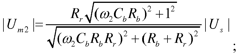 obtaining the insulation resistance parallel value Rb and the parasitic capacitance parallel value Cb of the to-be-detected battery through calculation according to the equation (1) and the equation (2), wherein Rr represents a resistance value of the first resistor.
 - The method according to claim 11, wherein the obtaining a positive electrode insulation resistance and a negative electrode insulation resistance of the to-be-detected battery comprises:controlling to turn off the alternating-current signal source;closing the first switch, obtaining a voltage Un1 of the third resistor through detection, and constructing an equation (3) based on a voltage U of the to-be-detected battery and the voltage Un1 of the third resistor:
 closing the first switch and the second switch, obtaining a voltage Un2 of the third resistor through detection, and constructing an equation (4) based on the voltage U of the to-be-detected battery and the voltage Un2 of the third resistor:
 obtaining the positive electrode insulation resistance Rp and the negative electrode insulation resistance Rn of the to-be-detected battery through calculation according to the equation (3), the equation (4), and an equation (5)
 R1 represents a resistance value of the second resistor, R2 represents a resistance value of the third resistor, R3 represents a resistance value of a fourth resistor, and Rb represents the insulation resistance parallel value of the to-be-detected battery.
 - The method according to claim 13, wherein the determining, based on the positive electrode insulation resistance and the negative electrode insulation resistance, whether an insulation failure occurs on the to-be-detected battery comprises:if both the positive electrode insulation resistance and the negative electrode insulation resistance are greater than the resistance threshold, determining that no insulation failure occurs on the to-be-detected battery; orif neither the positive electrode insulation resistance nor the negative electrode insulation resistance is greater than the resistance threshold, determining that an insulation failure occurs on the to-be-detected battery.
- An insulation resistance detection apparatus (10) comprising the insulation resistance detection circuit according to any one of claims 1 to 8, wherein the apparatus further comprises:a processor (11), configured to: control the alternating-current signal source to provide an alternating-current signal, and detect a voltage of the first resistor, whereinthe processor is further configured to: construct an equation based on the alternating-current signal and the voltage of the first resistor, and obtain an insulation resistance parallel value and a parasitic capacitance parallel value of a to-be-detected battery.
- The apparatus according to claim 15, wherein the processor is further configured to determine, based on the insulation resistance parallel value, whether an insulation failure occurs on the to-be-detected battery.
- The apparatus according to claim 16, wherein the processor is specifically configured to:if the insulation resistance parallel value is greater than a preset resistance threshold, determine that no insulation failure occurs on the to-be-detected battery;if the insulation resistance parallel value is less than the resistance threshold and greater than half of the resistance threshold, obtain a positive electrode insulation resistance and a negative electrode insulation resistance of the to-be-detected battery, and determine, based on the positive electrode insulation resistance and the negative electrode insulation resistance, whether an insulation failure occurs on the to-be-detected battery; orif the insulation resistance parallel value is less than half of the resistance threshold, determine that an insulation failure occurs on the to-be-detected battery.
- The apparatus according to any one of claims 15 to 17, wherein the processor is further specifically configured to:control to disconnect the first switch and the second switch;control the alternating-current signal source to inject a sine signal with a frequency ω1 and an amplitude value Us, and detect that a voltage at two ends of the first resistor is Um1; andcontrol the alternating-current signal source to inject a sine signal with a frequency ω2 and an amplitude value Us, and detect that a voltage at the two ends of the first resistor is Um2; andthe constructing an equation based on the alternating-current signal and the voltage of the first resistor, and obtaining an insulation resistance parallel value and a parasitic capacitance parallel value of a to-be-detected battery comprises:constructing an equation (1) based on Us and Um1:
 constructing an equation (2) based on Us and Um2:
 obtaining the insulation resistance parallel value Rb and the parasitic capacitance parallel value Cb of the to-be-detected battery through calculation according to the equation (1) and the equation (2), wherein Rr represents a resistance value of the first resistor.
 - The apparatus according to claim 17, wherein the processor is further specifically configured to:control to turn off the alternating-current signal source;close the first switch, obtain a voltage Un1 of the third resistor through detection, and construct an equation (3) based on a voltage U of the to-be-detected battery and the voltage Un1 of the third resistor:
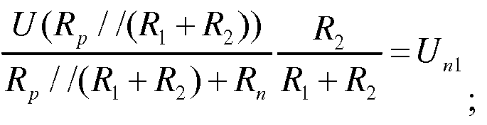 close the first switch and the second switch, obtain a voltage Un2 of the third resistor through detection, and construct an equation (4) based on the voltage U of the to-be-detected battery and the voltage Un1 of the third resistor:
 obtain the positive electrode insulation resistance Rp and the negative electrode insulation resistance Rn of the to-be-detected battery through calculation according to the equation (3), the equation (4), and an equation (5)
 R1 represents a resistance value of the second resistor, R2 represents a resistance value of the third resistor, R3 represents a resistance value of a fourth resistor, and Rb represents the insulation resistance parallel value of the to-be-detected battery.
 - The apparatus according to claim 19, wherein the processor is further configured to:if both the positive electrode insulation resistance and the negative electrode insulation resistance are greater than the resistance threshold, determine that no insulation failure occurs on the to-be-detected battery; orif neither the positive electrode insulation resistance nor the negative electrode insulation resistance is greater than the resistance threshold, determine that an insulation failure occurs on the to-be-detected battery.
- A device, comprising at least one processor, a memory, and a communications interface, wherein the at least one processor, the memory, and the communications interface are connected to each other; the memory stores a computer-executable instruction; and the at least one processor executes the computer-executable instruction stored in the memory, so that the device exchanges data with an insulation resistance detection circuit of the device through the communications interface to perform the insulation resistance detection method according to any one of claims 9 to 14.
- A readable storage medium, wherein the readable storage medium stores a computer-executable instruction, and when at least one processor of a device executes the computer-executable instruction, the device performs the insulation resistance detection method according to any one of claims 9 to 14.
Applications Claiming Priority (2)
| Application Number | Priority Date | Filing Date | Title |
|---|---|---|---|
| CN201710306654.0A CN108802494B (en) | 2017-05-03 | 2017-05-03 | Detection circuit, detection method and device of insulation resistance |
| PCT/CN2018/085092 WO2018202007A1 (en) | 2017-05-03 | 2018-04-28 | Detection circuit and detection method for insulation resistance and device |
Publications (3)
| Publication Number | Publication Date |
|---|---|
| EP3617725A1 EP3617725A1 (en) | 2020-03-04 |
| EP3617725A4 EP3617725A4 (en) | 2020-05-06 |
| EP3617725B1 true EP3617725B1 (en) | 2021-03-17 |
Family
ID=64015856
Family Applications (1)
| Application Number | Title | Priority Date | Filing Date |
|---|---|---|---|
| EP18794181.0A Active EP3617725B1 (en) | 2017-05-03 | 2018-04-28 | Detection circuit and detection method for insulation resistance and device |
Country Status (4)
| Country | Link |
|---|---|
| US (1) | US11243259B2 (en) |
| EP (1) | EP3617725B1 (en) |
| CN (1) | CN108802494B (en) |
| WO (1) | WO2018202007A1 (en) |
Families Citing this family (36)
| Publication number | Priority date | Publication date | Assignee | Title |
|---|---|---|---|---|
| LU100318B1 (en) * | 2017-06-15 | 2018-12-18 | Iee Sa | Capacitive Occupant Detection System with Improved Discrimination Capability |
| WO2020113413A1 (en) * | 2018-12-04 | 2020-06-11 | 深圳先进技术研究院 | Battery pack insulation testing method and system, electronic device, and storage medium |
| CN109471041B (en) * | 2019-01-08 | 2024-06-11 | 常州是为电子有限公司 | On-line monitoring device and method for insulation impedance of power battery |
| CN110967607A (en) * | 2019-01-15 | 2020-04-07 | 宁德时代新能源科技股份有限公司 | Insulation detection circuit, method and battery management system |
| CN110967560A (en) * | 2019-03-01 | 2020-04-07 | 宁德时代新能源科技股份有限公司 | Insulation detection circuit and detection method, battery management system |
| KR102672495B1 (en) * | 2019-03-15 | 2024-06-07 | 에스케이온 주식회사 | Apparatus for measuring insulation resistance |
| CN110095651A (en) * | 2019-05-13 | 2019-08-06 | 奇瑞新能源汽车技术有限公司 | A kind of online insulating resistor detecting circuit of power battery |
| FR3101425B1 (en) * | 2019-09-30 | 2021-10-15 | Renault Sas | Method for estimating the insulation resistance of a high voltage circuit of an electric or hybrid motor vehicle |
| US11226359B2 (en) * | 2019-10-31 | 2022-01-18 | Ravisekhar Nadimpalli Raju | System and method to generate multi-level voltage pulses for electrical insulation testing |
| CN111965425A (en) * | 2019-11-04 | 2020-11-20 | 中国石油大学(华东) | A three-phase three-wire low-voltage power distribution system insulation drop circuit selection method |
| CN110764022B (en) * | 2019-12-05 | 2025-11-18 | 杭州协能科技股份有限公司 | Diagnostic circuits and methods for grounding wire faults in insulated equipment |
| CN111289859A (en) * | 2020-03-19 | 2020-06-16 | 南京雁展科技有限公司 | Rapid direct-current insulation monitoring circuit and method |
| CN111337804A (en) * | 2020-04-16 | 2020-06-26 | 江苏智昂新能源科技有限公司 | Multi-channel direct-current insulation resistance detection protection circuit and protection method |
| CN111796204A (en) * | 2020-06-08 | 2020-10-20 | 力高(山东)新能源技术有限公司 | Method and system for judging voltage stability of new energy automobile by small signal insulation detection |
| CN111948504A (en) * | 2020-08-25 | 2020-11-17 | 的卢技术有限公司 | 800V energy storage system insulation detection circuit and method |
| CN111929505B (en) * | 2020-09-07 | 2025-03-25 | 爱士惟新能源技术(扬中)有限公司 | A circuit and method for detecting insulation impedance of a grid-connected inverter to ground |
| CN112285423B (en) * | 2020-10-26 | 2024-05-03 | 徐军平 | Method and system for rapidly calculating insulation resistance between anode and cathode and ground through fitting |
| CN112659898B (en) * | 2020-12-01 | 2023-08-18 | 珠海格力电器股份有限公司 | Fault diagnosis device and method for insulation resistance detection circuit of automobile and automobile |
| CN112666431B (en) * | 2020-12-21 | 2022-08-26 | 海南大学 | Full-state insulation detection control method for direct-current high-voltage system of electric vehicle |
| CN112858849B (en) * | 2021-01-08 | 2023-04-28 | 度普(苏州)新能源科技有限公司 | Offline detection method and device with insulation detection function |
| RU2756380C1 (en) * | 2021-01-27 | 2021-09-29 | Общество с ограниченной ответственностью Научно-производственное предприятие "ЭКРА" | Method for determining insulation resistance of network and insulation resistances of ac connections with isolated neutral of more than 1000 v |
| CN114910699B (en) * | 2021-02-09 | 2025-10-24 | 华为数字能源技术有限公司 | A converter system, system insulation impedance detection method, device and medium |
| CN113030576B (en) * | 2021-03-11 | 2024-09-24 | 福建星云电子股份有限公司 | Alternating current injection insulation resistance detection circuit and method |
| CN113009302B (en) * | 2021-03-18 | 2023-03-21 | 奇瑞新能源汽车股份有限公司 | Method and device for positioning insulation fault of high-voltage system of electric automobile |
| CN113252980B (en) | 2021-03-31 | 2025-02-25 | 华为数字能源技术有限公司 | A photovoltaic storage system and a method for detecting insulation impedance to ground |
| CN113687233B (en) * | 2021-08-27 | 2024-06-14 | 陈永强 | Monitoring and alarm method for battery pack disconnection from DC bus and poor contact |
| CN114137309A (en) * | 2021-12-02 | 2022-03-04 | 奇瑞商用车(安徽)有限公司 | Anti-interference insulation detection method for electric automobile |
| CN115099157B (en) * | 2022-07-15 | 2025-02-11 | 上海洛轲智能科技有限公司 | Prediction method and prediction device for insulation resistance of extended-range vehicle |
| CN115290978B (en) * | 2022-07-28 | 2025-06-24 | 法法汽车(中国)有限公司 | Insulation resistance detection device, vehicle and insulation resistance value determination method |
| CN115902670B (en) * | 2022-10-12 | 2026-03-10 | 欣捷安汽车电子有限公司 | Insulation detection method, system and equipment based on frequency conversion small signal injection |
| KR20240088485A (en) * | 2022-12-13 | 2024-06-20 | 엘지이노텍 주식회사 | Resistance measurement apparatus |
| CN116298968A (en) * | 2023-02-28 | 2023-06-23 | 万向一二三股份公司 | A method and system for non-destructive detection of module liquid leakage location |
| CN116953360B (en) * | 2023-09-20 | 2024-01-19 | 上海派能能源科技股份有限公司 | A rapid detection method for insulation resistance of energy storage equipment |
| CN117434408B (en) * | 2023-12-15 | 2024-03-29 | 珠海科创储能科技有限公司 | Battery insulation detection circuits, methods, devices, storage media and electronic equipment |
| CN118091523B (en) * | 2024-04-25 | 2024-08-30 | 宁德时代新能源科技股份有限公司 | Detection circuit, detection equipment and detection method |
| CN118604450A (en) * | 2024-05-28 | 2024-09-06 | 三一锂能有限公司 | Vehicle insulation resistance detection circuit, method, battery management system and vehicle |
Family Cites Families (16)
| Publication number | Priority date | Publication date | Assignee | Title |
|---|---|---|---|---|
| US20090033428A1 (en) | 2007-07-30 | 2009-02-05 | Mediatek Singapore Pte Ltd. | Voltage controlled oscillator |
| US8446158B1 (en) * | 2007-11-09 | 2013-05-21 | Cypress Semiconductor Corporation | Compensation for parasitic capacitance of a capacitive sensor |
| WO2010045662A2 (en) * | 2008-10-15 | 2010-04-22 | Azoteq (Pty) Ltd | Parasitic capacitance cancellation in capacitive measurement applications |
| CN101412433A (en) | 2008-11-14 | 2009-04-22 | 大连船舶重工集团有限公司 | Non-living accommodation on shipping based on corrugated polychromic steel plate design |
| EP2256506B1 (en) | 2009-05-27 | 2019-07-03 | Bender GmbH & Co. KG | Method and device for insulation monitoring of unearthed direct voltage and alternating current networks |
| CN102053183B (en) * | 2009-11-10 | 2015-04-22 | 北京普源精电科技有限公司 | Digital oscilloscope with impedance matching function |
| KR101354583B1 (en) * | 2010-09-17 | 2014-01-22 | 에스케이이노베이션 주식회사 | Insulation resistance measurement circuit |
| JP6210976B2 (en) * | 2011-05-23 | 2017-10-11 | コーニンクレッカ フィリップス エヌ ヴェKoninklijke Philips N.V. | FET switch as detuning circuit for MRIRF coil |
| US20130027049A1 (en) * | 2011-07-28 | 2013-01-31 | Tesla Motors, Inc. | Method for Determining Battery Pack Isolation Resistance Via Dual Bus Monitoring |
| KR101470553B1 (en) * | 2012-03-26 | 2014-12-10 | 주식회사 엘지화학 | Apparatus and method for measuring isolation resistance of battery |
| CN102854395B (en) | 2012-09-04 | 2015-10-21 | 阳光电源(上海)有限公司 | A kind of direct-current power ground insulation resistance detecting circuit and detection method thereof |
| CN104142433A (en) | 2013-05-09 | 2014-11-12 | 中南大学 | Active type direct-current system insulation resistor detection method |
| US9164151B2 (en) * | 2013-08-07 | 2015-10-20 | Lg Chem, Ltd. | System and method for determining isolation resistances of a battery pack |
| CN103472306B (en) * | 2013-09-06 | 2016-04-13 | 富奥汽车零部件股份有限公司 | A kind of electric automobile high-voltage insulation detecting method and system |
| KR101771226B1 (en) | 2014-10-02 | 2017-09-05 | 주식회사 엘지화학 | Isolation resistance measurement apparatus that can rapidly measure isolation resistance |
| CN105911353B (en) * | 2016-04-15 | 2018-09-14 | 广州汽车集团股份有限公司 | Automobile insulating resistor detecting circuit and its insulation resistance detection method |
-
2017
- 2017-05-03 CN CN201710306654.0A patent/CN108802494B/en active Active
-
2018
- 2018-04-28 WO PCT/CN2018/085092 patent/WO2018202007A1/en not_active Ceased
- 2018-04-28 EP EP18794181.0A patent/EP3617725B1/en active Active
-
2019
- 2019-11-04 US US16/673,666 patent/US11243259B2/en active Active
Non-Patent Citations (1)
| Title |
|---|
| None * |
Also Published As
| Publication number | Publication date |
|---|---|
| EP3617725A1 (en) | 2020-03-04 |
| US11243259B2 (en) | 2022-02-08 |
| CN108802494B (en) | 2020-03-20 |
| WO2018202007A1 (en) | 2018-11-08 |
| EP3617725A4 (en) | 2020-05-06 |
| CN108802494A (en) | 2018-11-13 |
| US20200064410A1 (en) | 2020-02-27 |
Similar Documents
| Publication | Publication Date | Title |
|---|---|---|
| US11243259B2 (en) | Insulation resistance detection circuit, detection method, and detection apparatus | |
| EP3521840B1 (en) | Insulation detection circuit and method, and battery management system | |
| CN111060791B (en) | Insulation fault detection method and device, electric vehicle, terminal equipment and medium | |
| US9261551B2 (en) | Ground fault detecting device for an ungrounded circuit | |
| CN110398633B (en) | A kind of insulation resistance detection method of electric vehicle | |
| CN102707627B (en) | The battery unit analogue system that can carry out in real time and method | |
| US20150241517A1 (en) | Method For Calculating Remaining Capacity Of Power Battery Pack | |
| JP5382813B2 (en) | Earth leakage detector | |
| KR102021438B1 (en) | Method and system for estimating the insulation resistance between a battery and an electrical earth | |
| CN102841284A (en) | On-line insulated monitoring method for high voltage of electromobile | |
| CN110596606A (en) | Method, system and device for estimating remaining power of lithium battery | |
| CN206235668U (en) | A kind of electric automobile high-voltage insulation fault identifying device | |
| CN110967560A (en) | Insulation detection circuit and detection method, battery management system | |
| CN107238803A (en) | Method and computer-readable recording medium for estimating battery SOE | |
| CN102624012B (en) | Method for distinguishing negative damping low frequency oscillation on the basis of moment decomposition integral algorithm | |
| CN107346002B (en) | For estimating the method and computer readable storage medium of battery SOE | |
| CN102520318A (en) | Fault recognition method for electric transmission line | |
| EP3521094B1 (en) | Method and device for obtaining internal side, external side insulation resistances of relay, and battery management system | |
| CN111830333A (en) | High-voltage safety test system | |
| Mukhopadhyay et al. | Adaptive detection of terminal voltage collapses for Li-ion batteries | |
| WO2020177575A1 (en) | Method and apparatus for detecting an insulation resistance value, and electronic device and storage medium | |
| EP3422025B1 (en) | Method and apparatus for frequency adjustment | |
| EP3879285B1 (en) | Insulation detection circuit of vehicle-mounted bidirectional charger and detection method therefor | |
| CN110108939A (en) | Alternating current motor insulation impedance obtaining method and device based on alternating current injection method | |
| Liu et al. | A selection method of mutual inductance identification models based on sensitivity analysis for wireless electric vehicles charging |
Legal Events
| Date | Code | Title | Description |
|---|---|---|---|
| STAA | Information on the status of an ep patent application or granted ep patent |
Free format text: STATUS: THE INTERNATIONAL PUBLICATION HAS BEEN MADE |
|
| PUAI | Public reference made under article 153(3) epc to a published international application that has entered the european phase |
Free format text: ORIGINAL CODE: 0009012 |
|
| STAA | Information on the status of an ep patent application or granted ep patent |
Free format text: STATUS: REQUEST FOR EXAMINATION WAS MADE |
|
| 17P | Request for examination filed |
Effective date: 20191126 |
|
| AK | Designated contracting states |
Kind code of ref document: A1 Designated state(s): AL AT BE BG CH CY CZ DE DK EE ES FI FR GB GR HR HU IE IS IT LI LT LU LV MC MK MT NL NO PL PT RO RS SE SI SK SM TR |
|
| AX | Request for extension of the european patent |
Extension state: BA ME |
|
| A4 | Supplementary search report drawn up and despatched |
Effective date: 20200407 |
|
| RIC1 | Information provided on ipc code assigned before grant |
Ipc: G01R 31/36 20200101AFI20200401BHEP Ipc: G01R 27/02 20060101ALI20200401BHEP Ipc: G01R 31/385 20190101ALI20200401BHEP Ipc: G01R 31/389 20190101ALI20200401BHEP |
|
| DAV | Request for validation of the european patent (deleted) | ||
| DAX | Request for extension of the european patent (deleted) | ||
| GRAP | Despatch of communication of intention to grant a patent |
Free format text: ORIGINAL CODE: EPIDOSNIGR1 |
|
| STAA | Information on the status of an ep patent application or granted ep patent |
Free format text: STATUS: GRANT OF PATENT IS INTENDED |
|
| INTG | Intention to grant announced |
Effective date: 20201019 |
|
| GRAS | Grant fee paid |
Free format text: ORIGINAL CODE: EPIDOSNIGR3 |
|
| GRAA | (expected) grant |
Free format text: ORIGINAL CODE: 0009210 |
|
| STAA | Information on the status of an ep patent application or granted ep patent |
Free format text: STATUS: THE PATENT HAS BEEN GRANTED |
|
| AK | Designated contracting states |
Kind code of ref document: B1 Designated state(s): AL AT BE BG CH CY CZ DE DK EE ES FI FR GB GR HR HU IE IS IT LI LT LU LV MC MK MT NL NO PL PT RO RS SE SI SK SM TR |
|
| REG | Reference to a national code |
Ref country code: GB Ref legal event code: FG4D |
|
| REG | Reference to a national code |
Ref country code: CH Ref legal event code: EP |
|
| REG | Reference to a national code |
Ref country code: DE Ref legal event code: R096 Ref document number: 602018014163 Country of ref document: DE |
|
| REG | Reference to a national code |
Ref country code: IE Ref legal event code: FG4D |
|
| REG | Reference to a national code |
Ref country code: AT Ref legal event code: REF Ref document number: 1372729 Country of ref document: AT Kind code of ref document: T Effective date: 20210415 |
|
| REG | Reference to a national code |
Ref country code: LT Ref legal event code: MG9D |
|
| PG25 | Lapsed in a contracting state [announced via postgrant information from national office to epo] |
Ref country code: BG Free format text: LAPSE BECAUSE OF FAILURE TO SUBMIT A TRANSLATION OF THE DESCRIPTION OR TO PAY THE FEE WITHIN THE PRESCRIBED TIME-LIMIT Effective date: 20210617 Ref country code: FI Free format text: LAPSE BECAUSE OF FAILURE TO SUBMIT A TRANSLATION OF THE DESCRIPTION OR TO PAY THE FEE WITHIN THE PRESCRIBED TIME-LIMIT Effective date: 20210317 Ref country code: GR Free format text: LAPSE BECAUSE OF FAILURE TO SUBMIT A TRANSLATION OF THE DESCRIPTION OR TO PAY THE FEE WITHIN THE PRESCRIBED TIME-LIMIT Effective date: 20210618 Ref country code: HR Free format text: LAPSE BECAUSE OF FAILURE TO SUBMIT A TRANSLATION OF THE DESCRIPTION OR TO PAY THE FEE WITHIN THE PRESCRIBED TIME-LIMIT Effective date: 20210317 Ref country code: NO Free format text: LAPSE BECAUSE OF FAILURE TO SUBMIT A TRANSLATION OF THE DESCRIPTION OR TO PAY THE FEE WITHIN THE PRESCRIBED TIME-LIMIT Effective date: 20210617 |
|
| REG | Reference to a national code |
Ref country code: AT Ref legal event code: MK05 Ref document number: 1372729 Country of ref document: AT Kind code of ref document: T Effective date: 20210317 |
|
| REG | Reference to a national code |
Ref country code: NL Ref legal event code: MP Effective date: 20210317 |
|
| PG25 | Lapsed in a contracting state [announced via postgrant information from national office to epo] |
Ref country code: LV Free format text: LAPSE BECAUSE OF FAILURE TO SUBMIT A TRANSLATION OF THE DESCRIPTION OR TO PAY THE FEE WITHIN THE PRESCRIBED TIME-LIMIT Effective date: 20210317 Ref country code: RS Free format text: LAPSE BECAUSE OF FAILURE TO SUBMIT A TRANSLATION OF THE DESCRIPTION OR TO PAY THE FEE WITHIN THE PRESCRIBED TIME-LIMIT Effective date: 20210317 Ref country code: SE Free format text: LAPSE BECAUSE OF FAILURE TO SUBMIT A TRANSLATION OF THE DESCRIPTION OR TO PAY THE FEE WITHIN THE PRESCRIBED TIME-LIMIT Effective date: 20210317 |
|
| PG25 | Lapsed in a contracting state [announced via postgrant information from national office to epo] |
Ref country code: NL Free format text: LAPSE BECAUSE OF FAILURE TO SUBMIT A TRANSLATION OF THE DESCRIPTION OR TO PAY THE FEE WITHIN THE PRESCRIBED TIME-LIMIT Effective date: 20210317 |
|
| PG25 | Lapsed in a contracting state [announced via postgrant information from national office to epo] |
Ref country code: SM Free format text: LAPSE BECAUSE OF FAILURE TO SUBMIT A TRANSLATION OF THE DESCRIPTION OR TO PAY THE FEE WITHIN THE PRESCRIBED TIME-LIMIT Effective date: 20210317 Ref country code: AT Free format text: LAPSE BECAUSE OF FAILURE TO SUBMIT A TRANSLATION OF THE DESCRIPTION OR TO PAY THE FEE WITHIN THE PRESCRIBED TIME-LIMIT Effective date: 20210317 Ref country code: LT Free format text: LAPSE BECAUSE OF FAILURE TO SUBMIT A TRANSLATION OF THE DESCRIPTION OR TO PAY THE FEE WITHIN THE PRESCRIBED TIME-LIMIT Effective date: 20210317 Ref country code: CZ Free format text: LAPSE BECAUSE OF FAILURE TO SUBMIT A TRANSLATION OF THE DESCRIPTION OR TO PAY THE FEE WITHIN THE PRESCRIBED TIME-LIMIT Effective date: 20210317 Ref country code: EE Free format text: LAPSE BECAUSE OF FAILURE TO SUBMIT A TRANSLATION OF THE DESCRIPTION OR TO PAY THE FEE WITHIN THE PRESCRIBED TIME-LIMIT Effective date: 20210317 |
|
| PG25 | Lapsed in a contracting state [announced via postgrant information from national office to epo] |
Ref country code: IS Free format text: LAPSE BECAUSE OF FAILURE TO SUBMIT A TRANSLATION OF THE DESCRIPTION OR TO PAY THE FEE WITHIN THE PRESCRIBED TIME-LIMIT Effective date: 20210717 Ref country code: PL Free format text: LAPSE BECAUSE OF FAILURE TO SUBMIT A TRANSLATION OF THE DESCRIPTION OR TO PAY THE FEE WITHIN THE PRESCRIBED TIME-LIMIT Effective date: 20210317 Ref country code: SK Free format text: LAPSE BECAUSE OF FAILURE TO SUBMIT A TRANSLATION OF THE DESCRIPTION OR TO PAY THE FEE WITHIN THE PRESCRIBED TIME-LIMIT Effective date: 20210317 Ref country code: RO Free format text: LAPSE BECAUSE OF FAILURE TO SUBMIT A TRANSLATION OF THE DESCRIPTION OR TO PAY THE FEE WITHIN THE PRESCRIBED TIME-LIMIT Effective date: 20210317 Ref country code: PT Free format text: LAPSE BECAUSE OF FAILURE TO SUBMIT A TRANSLATION OF THE DESCRIPTION OR TO PAY THE FEE WITHIN THE PRESCRIBED TIME-LIMIT Effective date: 20210719 |
|
| REG | Reference to a national code |
Ref country code: DE Ref legal event code: R097 Ref document number: 602018014163 Country of ref document: DE |
|
| PG25 | Lapsed in a contracting state [announced via postgrant information from national office to epo] |
Ref country code: LU Free format text: LAPSE BECAUSE OF NON-PAYMENT OF DUE FEES Effective date: 20210428 |
|
| REG | Reference to a national code |
Ref country code: BE Ref legal event code: MM Effective date: 20210430 |
|
| PLBE | No opposition filed within time limit |
Free format text: ORIGINAL CODE: 0009261 |
|
| STAA | Information on the status of an ep patent application or granted ep patent |
Free format text: STATUS: NO OPPOSITION FILED WITHIN TIME LIMIT |
|
| PG25 | Lapsed in a contracting state [announced via postgrant information from national office to epo] |
Ref country code: LI Free format text: LAPSE BECAUSE OF NON-PAYMENT OF DUE FEES Effective date: 20210430 Ref country code: MC Free format text: LAPSE BECAUSE OF FAILURE TO SUBMIT A TRANSLATION OF THE DESCRIPTION OR TO PAY THE FEE WITHIN THE PRESCRIBED TIME-LIMIT Effective date: 20210317 Ref country code: DK Free format text: LAPSE BECAUSE OF FAILURE TO SUBMIT A TRANSLATION OF THE DESCRIPTION OR TO PAY THE FEE WITHIN THE PRESCRIBED TIME-LIMIT Effective date: 20210317 Ref country code: CH Free format text: LAPSE BECAUSE OF NON-PAYMENT OF DUE FEES Effective date: 20210430 Ref country code: AL Free format text: LAPSE BECAUSE OF FAILURE TO SUBMIT A TRANSLATION OF THE DESCRIPTION OR TO PAY THE FEE WITHIN THE PRESCRIBED TIME-LIMIT Effective date: 20210317 Ref country code: ES Free format text: LAPSE BECAUSE OF FAILURE TO SUBMIT A TRANSLATION OF THE DESCRIPTION OR TO PAY THE FEE WITHIN THE PRESCRIBED TIME-LIMIT Effective date: 20210317 |
|
| 26N | No opposition filed |
Effective date: 20211220 |
|
| PG25 | Lapsed in a contracting state [announced via postgrant information from national office to epo] |
Ref country code: SI Free format text: LAPSE BECAUSE OF FAILURE TO SUBMIT A TRANSLATION OF THE DESCRIPTION OR TO PAY THE FEE WITHIN THE PRESCRIBED TIME-LIMIT Effective date: 20210317 |
|
| PG25 | Lapsed in a contracting state [announced via postgrant information from national office to epo] |
Ref country code: IT Free format text: LAPSE BECAUSE OF FAILURE TO SUBMIT A TRANSLATION OF THE DESCRIPTION OR TO PAY THE FEE WITHIN THE PRESCRIBED TIME-LIMIT Effective date: 20210317 Ref country code: IE Free format text: LAPSE BECAUSE OF NON-PAYMENT OF DUE FEES Effective date: 20210428 |
|
| PG25 | Lapsed in a contracting state [announced via postgrant information from national office to epo] |
Ref country code: IS Free format text: LAPSE BECAUSE OF FAILURE TO SUBMIT A TRANSLATION OF THE DESCRIPTION OR TO PAY THE FEE WITHIN THE PRESCRIBED TIME-LIMIT Effective date: 20210717 |
|
| PG25 | Lapsed in a contracting state [announced via postgrant information from national office to epo] |
Ref country code: BE Free format text: LAPSE BECAUSE OF NON-PAYMENT OF DUE FEES Effective date: 20210430 |
|
| PG25 | Lapsed in a contracting state [announced via postgrant information from national office to epo] |
Ref country code: CY Free format text: LAPSE BECAUSE OF FAILURE TO SUBMIT A TRANSLATION OF THE DESCRIPTION OR TO PAY THE FEE WITHIN THE PRESCRIBED TIME-LIMIT Effective date: 20210317 |
|
| PG25 | Lapsed in a contracting state [announced via postgrant information from national office to epo] |
Ref country code: HU Free format text: LAPSE BECAUSE OF FAILURE TO SUBMIT A TRANSLATION OF THE DESCRIPTION OR TO PAY THE FEE WITHIN THE PRESCRIBED TIME-LIMIT; INVALID AB INITIO Effective date: 20180428 |
|
| PG25 | Lapsed in a contracting state [announced via postgrant information from national office to epo] |
Ref country code: MK Free format text: LAPSE BECAUSE OF FAILURE TO SUBMIT A TRANSLATION OF THE DESCRIPTION OR TO PAY THE FEE WITHIN THE PRESCRIBED TIME-LIMIT Effective date: 20210317 |
|
| PG25 | Lapsed in a contracting state [announced via postgrant information from national office to epo] |
Ref country code: TR Free format text: LAPSE BECAUSE OF FAILURE TO SUBMIT A TRANSLATION OF THE DESCRIPTION OR TO PAY THE FEE WITHIN THE PRESCRIBED TIME-LIMIT Effective date: 20210317 |
|
| PG25 | Lapsed in a contracting state [announced via postgrant information from national office to epo] |
Ref country code: MT Free format text: LAPSE BECAUSE OF FAILURE TO SUBMIT A TRANSLATION OF THE DESCRIPTION OR TO PAY THE FEE WITHIN THE PRESCRIBED TIME-LIMIT Effective date: 20210317 |
|
| REG | Reference to a national code |
Ref country code: DE Ref legal event code: R081 Ref document number: 602018014163 Country of ref document: DE Owner name: SHENZHEN YINWANG INTELLIGENT TECHNOLOGIES CO.,, CN Free format text: FORMER OWNER: HUAWEI TECHNOLOGIES CO., LTD., SHENZHEN, GUANGDONG, CN |
|
| REG | Reference to a national code |
Ref country code: GB Ref legal event code: 732E Free format text: REGISTERED BETWEEN 20241128 AND 20241204 |
|
| PGFP | Annual fee paid to national office [announced via postgrant information from national office to epo] |
Ref country code: DE Payment date: 20250305 Year of fee payment: 8 |
|
| PGFP | Annual fee paid to national office [announced via postgrant information from national office to epo] |
Ref country code: GB Payment date: 20260313 Year of fee payment: 9 |
|
| PGFP | Annual fee paid to national office [announced via postgrant information from national office to epo] |
Ref country code: FR Payment date: 20260309 Year of fee payment: 9 |