EP3617699A1 - Detection system and detection method - Google Patents
Detection system and detection method Download PDFInfo
- Publication number
- EP3617699A1 EP3617699A1 EP18791366.0A EP18791366A EP3617699A1 EP 3617699 A1 EP3617699 A1 EP 3617699A1 EP 18791366 A EP18791366 A EP 18791366A EP 3617699 A1 EP3617699 A1 EP 3617699A1
- Authority
- EP
- European Patent Office
- Prior art keywords
- vibration
- inspection target
- vibration unit
- resonance frequency
- unit
- Prior art date
- Legal status (The legal status is an assumption and is not a legal conclusion. Google has not performed a legal analysis and makes no representation as to the accuracy of the status listed.)
- Granted
Links
Images






Classifications
-
- G—PHYSICS
- G01—MEASURING; TESTING
- G01N—INVESTIGATING OR ANALYSING MATERIALS BY DETERMINING THEIR CHEMICAL OR PHYSICAL PROPERTIES
- G01N29/00—Investigating or analysing materials by the use of ultrasonic, sonic or infrasonic waves; Visualisation of the interior of objects by transmitting ultrasonic or sonic waves through the object
- G01N29/04—Analysing solids
- G01N29/045—Analysing solids by imparting shocks to the workpiece and detecting the vibrations or the acoustic waves caused by the shocks
-
- B—PERFORMING OPERATIONS; TRANSPORTING
- B06—GENERATING OR TRANSMITTING MECHANICAL VIBRATIONS IN GENERAL
- B06B—METHODS OR APPARATUS FOR GENERATING OR TRANSMITTING MECHANICAL VIBRATIONS OF INFRASONIC, SONIC, OR ULTRASONIC FREQUENCY, e.g. FOR PERFORMING MECHANICAL WORK IN GENERAL
- B06B1/00—Methods or apparatus for generating mechanical vibrations of infrasonic, sonic, or ultrasonic frequency
- B06B1/02—Methods or apparatus for generating mechanical vibrations of infrasonic, sonic, or ultrasonic frequency making use of electrical energy
- B06B1/04—Methods or apparatus for generating mechanical vibrations of infrasonic, sonic, or ultrasonic frequency making use of electrical energy operating with electromagnetism
- B06B1/045—Methods or apparatus for generating mechanical vibrations of infrasonic, sonic, or ultrasonic frequency making use of electrical energy operating with electromagnetism using vibrating magnet, armature or coil system
-
- G—PHYSICS
- G01—MEASURING; TESTING
- G01H—MEASUREMENT OF MECHANICAL VIBRATIONS OR ULTRASONIC, SONIC OR INFRASONIC WAVES
- G01H13/00—Measuring resonant frequency
-
- G—PHYSICS
- G01—MEASURING; TESTING
- G01M—TESTING STATIC OR DYNAMIC BALANCE OF MACHINES OR STRUCTURES; TESTING OF STRUCTURES OR APPARATUS, NOT OTHERWISE PROVIDED FOR
- G01M5/00—Investigating the elasticity of structures, e.g. deflection of bridges or air-craft wings
- G01M5/0025—Investigating the elasticity of structures, e.g. deflection of bridges or air-craft wings of elongated objects, e.g. pipes, masts, towers or railways
-
- G—PHYSICS
- G01—MEASURING; TESTING
- G01M—TESTING STATIC OR DYNAMIC BALANCE OF MACHINES OR STRUCTURES; TESTING OF STRUCTURES OR APPARATUS, NOT OTHERWISE PROVIDED FOR
- G01M5/00—Investigating the elasticity of structures, e.g. deflection of bridges or air-craft wings
- G01M5/0033—Investigating the elasticity of structures, e.g. deflection of bridges or air-craft wings by determining damage, crack or wear
-
- G—PHYSICS
- G01—MEASURING; TESTING
- G01M—TESTING STATIC OR DYNAMIC BALANCE OF MACHINES OR STRUCTURES; TESTING OF STRUCTURES OR APPARATUS, NOT OTHERWISE PROVIDED FOR
- G01M5/00—Investigating the elasticity of structures, e.g. deflection of bridges or air-craft wings
- G01M5/0066—Investigating the elasticity of structures, e.g. deflection of bridges or air-craft wings by exciting or detecting vibration or acceleration
-
- G—PHYSICS
- G01—MEASURING; TESTING
- G01M—TESTING STATIC OR DYNAMIC BALANCE OF MACHINES OR STRUCTURES; TESTING OF STRUCTURES OR APPARATUS, NOT OTHERWISE PROVIDED FOR
- G01M5/00—Investigating the elasticity of structures, e.g. deflection of bridges or air-craft wings
- G01M5/0075—Investigating the elasticity of structures, e.g. deflection of bridges or air-craft wings by means of external apparatus, e.g. test benches or portable test systems
-
- G—PHYSICS
- G01—MEASURING; TESTING
- G01M—TESTING STATIC OR DYNAMIC BALANCE OF MACHINES OR STRUCTURES; TESTING OF STRUCTURES OR APPARATUS, NOT OTHERWISE PROVIDED FOR
- G01M5/00—Investigating the elasticity of structures, e.g. deflection of bridges or air-craft wings
- G01M5/0091—Investigating the elasticity of structures, e.g. deflection of bridges or air-craft wings by using electromagnetic excitation or detection
-
- G—PHYSICS
- G01—MEASURING; TESTING
- G01M—TESTING STATIC OR DYNAMIC BALANCE OF MACHINES OR STRUCTURES; TESTING OF STRUCTURES OR APPARATUS, NOT OTHERWISE PROVIDED FOR
- G01M7/00—Vibration-testing of structures; Shock-testing of structures
-
- G—PHYSICS
- G01—MEASURING; TESTING
- G01N—INVESTIGATING OR ANALYSING MATERIALS BY DETERMINING THEIR CHEMICAL OR PHYSICAL PROPERTIES
- G01N29/00—Investigating or analysing materials by the use of ultrasonic, sonic or infrasonic waves; Visualisation of the interior of objects by transmitting ultrasonic or sonic waves through the object
- G01N29/04—Analysing solids
-
- G—PHYSICS
- G01—MEASURING; TESTING
- G01N—INVESTIGATING OR ANALYSING MATERIALS BY DETERMINING THEIR CHEMICAL OR PHYSICAL PROPERTIES
- G01N29/00—Investigating or analysing materials by the use of ultrasonic, sonic or infrasonic waves; Visualisation of the interior of objects by transmitting ultrasonic or sonic waves through the object
- G01N29/04—Analysing solids
- G01N29/12—Analysing solids by measuring frequency or resonance of acoustic waves
-
- G—PHYSICS
- G01—MEASURING; TESTING
- G01N—INVESTIGATING OR ANALYSING MATERIALS BY DETERMINING THEIR CHEMICAL OR PHYSICAL PROPERTIES
- G01N29/00—Investigating or analysing materials by the use of ultrasonic, sonic or infrasonic waves; Visualisation of the interior of objects by transmitting ultrasonic or sonic waves through the object
- G01N29/22—Details, e.g. general constructional or apparatus details
- G01N29/24—Probes
- G01N29/2418—Probes using optoacoustic interaction with the material, e.g. laser radiation, photoacoustics
-
- G—PHYSICS
- G01—MEASURING; TESTING
- G01N—INVESTIGATING OR ANALYSING MATERIALS BY DETERMINING THEIR CHEMICAL OR PHYSICAL PROPERTIES
- G01N29/00—Investigating or analysing materials by the use of ultrasonic, sonic or infrasonic waves; Visualisation of the interior of objects by transmitting ultrasonic or sonic waves through the object
- G01N29/34—Generating the ultrasonic, sonic or infrasonic waves, e.g. electronic circuits specially adapted therefor
-
- G—PHYSICS
- G01—MEASURING; TESTING
- G01N—INVESTIGATING OR ANALYSING MATERIALS BY DETERMINING THEIR CHEMICAL OR PHYSICAL PROPERTIES
- G01N29/00—Investigating or analysing materials by the use of ultrasonic, sonic or infrasonic waves; Visualisation of the interior of objects by transmitting ultrasonic or sonic waves through the object
- G01N29/44—Processing the detected response signal, e.g. electronic circuits specially adapted therefor
- G01N29/4409—Processing the detected response signal, e.g. electronic circuits specially adapted therefor by comparison
- G01N29/4427—Processing the detected response signal, e.g. electronic circuits specially adapted therefor by comparison with stored values, e.g. threshold values
-
- G—PHYSICS
- G01—MEASURING; TESTING
- G01N—INVESTIGATING OR ANALYSING MATERIALS BY DETERMINING THEIR CHEMICAL OR PHYSICAL PROPERTIES
- G01N29/00—Investigating or analysing materials by the use of ultrasonic, sonic or infrasonic waves; Visualisation of the interior of objects by transmitting ultrasonic or sonic waves through the object
- G01N29/44—Processing the detected response signal, e.g. electronic circuits specially adapted therefor
- G01N29/4409—Processing the detected response signal, e.g. electronic circuits specially adapted therefor by comparison
- G01N29/4436—Processing the detected response signal, e.g. electronic circuits specially adapted therefor by comparison with a reference signal
-
- G—PHYSICS
- G01—MEASURING; TESTING
- G01N—INVESTIGATING OR ANALYSING MATERIALS BY DETERMINING THEIR CHEMICAL OR PHYSICAL PROPERTIES
- G01N33/00—Investigating or analysing materials by specific methods not covered by groups G01N1/00 - G01N31/00
- G01N33/38—Concrete; Lime; Mortar; Gypsum; Bricks; Ceramics; Glass
- G01N33/383—Concrete or cement
-
- G—PHYSICS
- G01—MEASURING; TESTING
- G01N—INVESTIGATING OR ANALYSING MATERIALS BY DETERMINING THEIR CHEMICAL OR PHYSICAL PROPERTIES
- G01N2291/00—Indexing codes associated with group G01N29/00
- G01N2291/01—Indexing codes associated with the measuring variable
- G01N2291/014—Resonance or resonant frequency
-
- G—PHYSICS
- G01—MEASURING; TESTING
- G01N—INVESTIGATING OR ANALYSING MATERIALS BY DETERMINING THEIR CHEMICAL OR PHYSICAL PROPERTIES
- G01N2291/00—Indexing codes associated with group G01N29/00
- G01N2291/02—Indexing codes associated with the analysed material
- G01N2291/025—Change of phase or condition
-
- G—PHYSICS
- G01—MEASURING; TESTING
- G01N—INVESTIGATING OR ANALYSING MATERIALS BY DETERMINING THEIR CHEMICAL OR PHYSICAL PROPERTIES
- G01N2291/00—Indexing codes associated with group G01N29/00
- G01N2291/10—Number of transducers
- G01N2291/101—Number of transducers one transducer
-
- G—PHYSICS
- G01—MEASURING; TESTING
- G01N—INVESTIGATING OR ANALYSING MATERIALS BY DETERMINING THEIR CHEMICAL OR PHYSICAL PROPERTIES
- G01N2291/00—Indexing codes associated with group G01N29/00
- G01N2291/10—Number of transducers
- G01N2291/102—Number of transducers one emitter, one receiver
Definitions
- the present invention generally relates to detection systems and detection methods, in particular to a detection system and a detection method for vibrating an inspection target by applying vibration to the inspection target and detecting a state change of the inspection target by analyzing the vibration of the inspection target.
- patent document 1 discloses a frequency measurement device including an excitation unit having an impulse hammer made from a hard material for applying impulse to an inspection target and a sensor for detecting vibration of the inspection target caused by the impulse applied from the excitation unit.
- an excitation unit having an impulse hammer made from a hard material for applying impulse to an inspection target
- a sensor for detecting vibration of the inspection target caused by the impulse applied from the excitation unit.
- patent document 2 discloses an abnormality detection system including an excitation unit having an impulse hammer made from a hard material or a piezoelectric element (piezo element) for vibrating an inspection target and a sensor for detecting vibration of the inspection target caused by impulse applied from the impulse hammer or vibration of the piezoelectric element.
- an excitation unit having an impulse hammer made from a hard material or a piezoelectric element (piezo element) for vibrating an inspection target and a sensor for detecting vibration of the inspection target caused by impulse applied from the impulse hammer or vibration of the piezoelectric element.
- the present invention has been made in view of the conventional problems mentioned above. Accordingly, it is an object of the present invention to achieve simplification, downsizing and power saving of a detection system which can detect a state change of an inspection target by detecting and analyzing vibration of the inspection target caused by vibration applied to the inspection target.
- the detection system and the detection method of the present invention use a VCM (Voice Coil Motor) type vibration unit as an excitation unit for vibrating an inspection target, which includes a coil in which an electrical signal supplied from a driving circuit flows, a spring provided so as to be capable of vibrating and a magnet attached to the spring so as to be apart from the coil.
- VCM Voice Coil Motor
- the vibration unit the excitation unit
- the VCM type vibration unit can cause big vibration with a relatively low input voltage, it is unnecessary to apply a high input voltage to the vibration unit unlike the conventional art using the piezoelectric element.
- it is possible to achieve simplification, downsizing and power saving of the detection system.
- Fig. 1 is a schematic view showing the detection system according to the first embodiment of the present invention.
- Fig. 2 is a perspective view of a vibration unit shown in Fig. 1 .
- Fig. 3 is an exploded perspective view of the vibration unit shown in Fig. 1 .
- Fig. 4 is a cross-sectional view of the vibration unit shown in Fig. 1 .
- Fig. 5 is a view showing examples of vibration of an inspection target caused when one of an impulse signal, a swept signal and a random signal is supplied to the vibration unit shown in Fig. 1 .
- Fig. 6 is a view showing other examples of the vibration of the inspection target caused when one of the impulse signal, the swept signal and the random signal is supplied to the vibration unit shown in Fig. 1 .
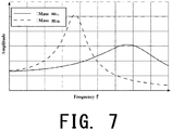
- Fig. 7 is a view for explaining a change in characteristics of the vibration of the inspection target caused by a change in a mass of the inspection target shown in Fig. 1 .
- a detection system 1 shown in Fig. 1 contains a sensing device 10 for applying vibration to an inspection target 100 and detecting vibration of the inspection target 100 caused by the applied vibration and a detection processing device 20 for detecting a state change of the inspection target 100 based on vibration information related to the vibration of the inspection target 100 received from the sensing device 10.
- the sensing device 10 has a function of applying the vibration to the inspection target 100 and detecting the vibration of the inspection target 100 caused by the applied vibration.
- the sensing device 10 includes a vibration unit 11 attached to the inspection target 100 for applying the vibration to the inspection target 100, a driving circuit 12 for supplying an electrical signal to the vibration unit 11 for driving the vibration unit 11, a sensor 13 for detecting the vibration of the inspection target 100 caused by the vibration applied from the vibration unit 11 and a communication unit 14 for performing communication with the detection processing device 20.
- the vibration unit 11 is attached to the inspection target 100 and vibrates according to the electrical signal supplied from the driving circuit 12.
- the vibration unit 11 is used for applying the vibration to the inspection target 100.
- the vibration unit 11 is a VCM (Voice Coil Motor) type vibration unit with a small size (for example, 30 mm height x 30 mm vertical width x 30 mm horizontal width) and constitutes a single resonance system.
- VCM Vehicle Coil Motor
- the vibration unit 11 includes a case 111 configured to be attachable to the inspection target 100, a coil 112 fixedly attached on a bottom surface of the case 111 and in which the electrical signal supplied from the driving circuit 12 flows, a spring 113 provided so as to be capable of vibrating with respect to the case 111 and a magnet assembly 114 attached to the spring 113 and provided so as to be apart from the coil 112.
- the case 111 is a cylindrical member.
- the case 111 has functions of fixing the vibration unit 11 to a vibrating body and containing each component of the vibration unit 11 therein.
- the case 111 includes a cover 111a, a base 111b and a cylindrical portion 111c located between the cover 111a and the base 111b.
- Three extending portions are formed on an outer peripheral surface of the base 111b so as to extend in a radial direction of the base 111b and through-holes 111d are respectively formed in tip side portions of the three extending portions. Screws (not shown in the drawings) are respectively passed through the through-holes 111d of the base 111b and respectively screwed with screw holes formed in the inspection target 100. Due to this operation, the base 111b is fixed to the inspection target 100 and thus the vibration unit 11 can be attached (fixed) to the inspection target 100. By attaching the vibration unit 11 to the inspection target 100, it becomes possible to transmit the vibration of the vibration unit 11 to the inspection target 100, thereby vibrating the inspection target 100.
- the coil 112 has a cylindrical shape and is fixedly provided on the base 111b. Both end portions (electrical signal supply terminals) of the coil 112 are connected to the driving circuit 12 and thus the electrical signal supplied from the driving circuit 12 flows in the coil 112. Further, as shown in Fig. 4 , the coil 112 is located inside a central opening portion of the spring 113 in a state that the vibration unit 11 has been assembled.
- the spring 113 has a function of holding the magnet assembly 114 so that the magnet assembly 114 can vibrate with respect to the coil 112.
- the magnet assembly 114 is attached to the spring 113.
- driving force for moving the magnet assembly 114 attached to the spring 113 in a vertical direction in Fig. 4 occurs.
- the magnet assembly 114 can vibrate with respect to the coil 112.
- the spring 113 is not particularly limited as long as it can hold the magnet assembly 114 so that the magnet assembly 114 can vibrate with respect to the coil 112.
- a leaf spring, a coil spring, a magnetic spring or the like can be used as the spring 113.
- the spring 113 is the leaf spring as shown in Figs. 3 and 4 .
- the spring 113 has a ring shape with the central opening portion. An outer peripheral portion of the spring 113 is held between the base 111b and the cylindrical portion 111c and a central portion of the spring 113 containing the central opening portion can vibrate with respect to the case 111 in the vertical direction in Fig. 4 .
- the magnet assembly 114 is attached to the central portion of the spring 113 and thus can vibrate with respect to the coil 112.
- the magnet assembly 114 includes a magnet holding portion 114a having a cylindrical shape opening toward a lower side in Fig. 4 , a magnet 114b fixed on a central lower surface of the magnet holding portion 114a and a yoke 114c attached to a lower surface of the magnet 114b.
- the magnet 114b and the yoke 114c are arranged in a central hollow portion of the coil 112 so as to be apart from the coil 112 in the state that the vibration unit 11 has been assembled.
- the driving force for moving the magnet assembly 114 (the magnet 114b) in the vertical direction in Fig. 4 . Since the magnet assembly 114 is attached to the spring 113 provided so as to be capable of vibrating, the magnet assembly 114 vibrates in the vertical direction.
- a motion equation for representing a motion principle of a single resonance system such as the vibration unit 11 can be represented by the following equation (1).
- m is a mass [kg]
- x(t) is a displacement amount [m] of the magnet assembly 114 (vibrator)
- K f is a thrust constant [N/A] of the single resonance system
- i(t) is a current [A] flowing in the coil 112
- K sp is a spring constant [N/m] of the spring 113
- D is a damping coefficient [N/(m/s)] of the single resonance system.
- a circuit equation for representing the motion principle of the single resonance system such as the vibration unit 11 can be represented by the following equation (2).
- e(t) is a voltage [V] applied to the coil 112
- R is a resistance [ ⁇ ] of the coil 112
- L is an inductance [H] of the coil 112
- K e is a counter electromotive force constant [V/(m/s)] of the single resonance system.
- a characteristic of the vibration of the vibration unit 11 changes depending on the kind of the electrical signal supplied to the vibration unit 11 from the driving circuit 12 (input to the single resonance system).
- Fig. 5 shows examples of the vibration of the inspection target 100 caused when each of an impulse signal, a swept signal and a random signal is supplied to the vibration unit 11 attached to the inspection target 100 for vibrating the vibration unit 11.
- a structure constituted of an ABS (Acrylonitrile Butadiene Styrene) resin is used as the inspection target 100.
- a resonance frequency f r of the inspection target 100 in this case is in the vicinity of 5 kHz.
- Fig. 6 shows other examples of the vibration of the inspection target 100 caused when each of the impulse signal, the swept signal and the random signal is supplied to the vibration unit 11 attached to the inspection target 100 for vibrating the vibration unit 11.
- a structure constituted of a plastic material is used as the inspection target 100.
- the mass and the spring constant of the inspection target 100 in the examples in Fig. 6 are different from the mass and the spring constant of the inspection target 100 in the examples in Fig. 5 .
- the resonance frequency f r of the inspection target 100 in this case of Fig. 6 is in the vicinity of 0.125 kHz.
- the amplitude shows a peak in a frequency range other than 0.125 kHz which is the resonance frequency f r of the inspection target 100.
- the swept signal or the random signal is supplied to the vibration unit 11, the amplitude maximizes in the vicinity of 0.125 kHz which is the resonance frequency f r of the inspection target 100.
- the resonance frequency f r of the vibration of the inspection target 100 cannot be accurately detected.
- the kind of the electrical signal which should be supplied to the vibration unit 11 from the driving circuit 12 changes depending on the mass and/or the spring constant of the inspection target 100. Since the driving circuit 12 is configured to supply one of the impulse signal, the swept signal and the random signal to the vibration unit 11 as described later, the sensing device 10 can detect the resonance frequency f r of the vibration of various kinds of inspection targets 100.
- the vibration unit 11 attached to the inspection target 100 vibrates, the vibration is applied to the inspection target 100.
- the vibration is applied to the inspection target 100 from the vibration unit 11, the vibration of the inspection target 100 is excited.
- the inspection target 100 vibrates, the inspection target 100 largely vibrates at the resonance frequency f r derived from the following equation (4) .
- m 1 is a mass of the inspection target 100
- m 2 is a mass of the vibration unit 11 attached to the inspection target 100
- K sp is a spring constant of the inspection target 100.
- the resonance frequency f r of the inspection target 100 changes depending on the mass m 1 and the spring constant K sp of the inspection target 100.
- the resonance frequency f r of the inspection target 100 changes depending on the mass m 1 and the spring constant K sp of the inspection target 100.
- Fig. 7 shows an example of a change of the resonance frequency f r of the inspection target 100 when the mass m 1 of the inspection target 100 increases from m 1a to m 1b due to the factors such as time elapse and breakdown.
- a frequency at which the amplitude of the vibration of the inspection target 100 maximizes that is, the resonance frequency f r is shifted to a lower frequency side.
- the resonance frequency f r of the inspection target 100 is shifted to a higher frequency side.
- the resonance frequency f r of the inspection target 100 is shifted to the higher frequency side.
- the resonance frequency f r of the inspection target 100 is shifted to the lower frequency side.
- Examples in which the mass m 1 of the inspection target 100 decreases due to the factors such as time elapse and breakdown contain a case where the inspection target 100 is a metallic member made from a metallic material such as an iron. When a part of the inspection target 100 falls due to corrosion or weathering with the lapse of time, the mass m 1 of the inspection target 100 decreases. On the other hand, examples in which the mass m 1 of the inspection target 100 increases due to the factors such as time elapse and breakdown contain a case where the inspection target 100 is arranged outside. When dusts, dirt, sands, water and/or the like are accumulated on the inspection target 100 with the lapse of time, the mass m 1 of the inspection target 100 increases.
- Examples in which the spring constant K sp of the inspection target 100 changes due to the factors such as time elapse and breakdown contain a case where the inspection target 100 is a structure constituted by coupling a plurality of parts with each other. For example, when bolts or screws for coupling the plurality of parts are loosened or beams among the parts are distorted, the spring constant K sp of the inspection target 100 changes. Further, in a case where the inspection target 100 is a wheel of a tire of a vehicle, the spring constant K sp of the inspection target 100 changes due to loosening of the wheel. Further, in a case where the inspection target 100 is a structure made from a concrete and cracks or breaks occur in the inspection target 100 due to some factors such as time elapse and impulse, the spring constant K sp of the inspection target 100 changes.
- the detection system 1 can detect a variety of events such as corrosion or weathering of the inspection target 100, increase of an accumulated material on the inspection target 100, loosening of the bolts or the screws of the inspection target 100, distortion of the beam of the inspection target 100, loosening of the wheel of the inspection target 100 and occurrence of the cracks or the breaks of the inspection target 100.
- the driving circuit 12 has a function of supplying the electrical signal to the vibration unit 11 for driving (vibrating) the vibration unit 11.
- the driving circuit 12 is configured to supply at least one of the impulse signal, the swept signal and the random signal to the vibration unit 11 according to control data received from the detecting processing device 20 through the communication unit 14.
- the sensor 13 has a function of detecting the vibration of the inspection target 100 caused by the vibration applied from the vibration unit 11. Vibration information related to the vibration of the inspection target 100 detected by the sensor 13 is transmitted to the detection processing device 20 through the communication unit 14.
- the vibration information transmitted to the detection processing device 20 from the sensor 13 is an acceleration or the like of the vibration (motion) of the inspection target 100.
- the sensor 13 is not particularly limited as long as it can detect the vibration of the inspection target 100.
- the communication unit 14 has a function of communicating with the detection processing device 20 to receive the control data from the detection processing device 20 and transmitting the vibration information related to the vibration of the inspection target 100 detected by the sensor 13 to the detection processing device 20.
- the communication unit 14 performs communication with the detection processing device 20 with wired communication.
- the communication unit 14 performs communication with the detection processing device 20 with a wireless communication technology such as an NFC (Near Field Radio Communication), a Wi-Fi and a Bluetooth (registered trademark).
- power supply to each component of the sensing device 10 may be achieved by an internal power source such as a battery build in the sensing device 10 or an external power source arranged outside the sensing device 10 and connected to the sensing device 10 with a power supply wire.
- an internal power source such as a battery build in the sensing device 10 or an external power source arranged outside the sensing device 10 and connected to the sensing device 10 with a power supply wire.
- the detection processing device 20 has functions of transmitting the control data to the sensing device 10, receiving the vibration information related to the vibration of the inspection target 100 detected by the sensor 13 from the sensing device 10 and detecting the state change of the inspection target 100 based on the received vibration information.
- the detection processing device 20 may be practiced as a stand-alone device or practiced in an arbitrary computing device such as a desktop computer, a laptop computer, a notebook computer, a workstation, a tablet computer, a mobile phone, a smart phone, a PDA and a wearable device.
- the detection processing device 20 includes at least one processor 21 for performing control for the detection processing device 20, a memory 22 storing data, programs, modules and the like required for performing the control of the detection processing device 20, a resonance frequency calculating part 23 for calculating the resonance frequency f r of the vibration of the inspection target 100 based on the received vibration information, a storage part 24 for storing the resonance frequency f r calculated by the resonance frequency calculating part 23 and/or a reference resonance frequency f ref of the vibration of the inspection target 100, a coherence calculating part 25 for calculating a coherence ⁇ 2 between the vibration of the vibration unit 11 of the sensing device 10 and the vibration of the inspection target 100, a state change detecting part 26 for detecting the state change of the inspection target 100 by comparing the resonance frequency f r of the vibration of the inspection target 100 calculated by the resonance frequency calculating part 23 with the reference resonance frequency f ref stored in the storage part 24 or a previous resonance frequency f r of the vibration of the inspection target 100 stored in the storage part 24, a communication unit
- the processor 21 performs, transmits and receives a variety of data or a variety of instructions with each component through the data bus 28 for performing the control of the detection processing device 20. Further, the processor 21 can provide desired functions by using each component of the detection processing device 20. For example, the processor 21 can use the resonance frequency calculating part 23 to calculate the resonance frequency f r of the vibration of the inspection target 100 based on the received vibration information, use the coherence calculating part 25 to calculate the coherence ⁇ 2 between the vibration of the vibration unit 11 of the sensing device 10 and the vibration of the inspection target 100 and use the state change detecting part 26 to detect the state change of the inspection target 100.
- the processor 21 transmits the control data to the sensing device 10 through the communication unit 27 at prescribed time intervals (such as every hour, every day, every week and every week) for allowing the sensing device 10 to measure the vibration of the inspection target 100.
- the control data transmitted from the processor 21 is used for identifying which one of the impulse signal, the swept signal and the random signal should be supplied to the vibrating unit 11 from the driving circuit 12 of the sensing device 10.
- the driving circuit 12 receiving the control data supplies one of the impulse signal, the swept signal and the random signal to the vibration unit 11 according to the control data for vibrating the vibration unit 11.
- the processor 21 is one or more operation units such as microprocessors, microcomputers, microcontrollers, digital signal processors (DSPs), central processing units (CPUs), memory control units (MCUs), graphic processing units (GPUs), state machines, logic circuitries, application specific integrated circuits (ASICs) and combinations thereof that can perform operational processes for manipulating signals or the like based on computer-readable instructions.
- the processor 21 is configured to fetch computer-readable instructions (such as data, programs and modules) stored in the memory 22 and execute signal control and signal manipulation.
- the memory 22 is one or more removable or non-removable computer-readable media including volatile memories (such as RAMs, SRAMs and DRAMs), non-volatile memories (such as ROMs, EPROMs, EEPROMs, flash memories, hard disks, optical discs, CD-ROMs, digital versatile discs (DVDs), magnetic cassettes, magnetic tapes and magnetic disks) and combinations thereof.
- volatile memories such as RAMs, SRAMs and DRAMs
- non-volatile memories such as ROMs, EPROMs, EEPROMs, flash memories, hard disks, optical discs, CD-ROMs, digital versatile discs (DVDs), magnetic cassettes, magnetic tapes and magnetic disks
- the resonance frequency calculating part 23 has a function of calculating the resonance frequency f r of the vibration of the inspection target 100 based on the vibration information received from the sensing device 10 through the communication unit 27. Specifically, the resonance frequency calculating part 23 performs the process such as a Fourier transformation with respect to the received vibration information to calculate the amplitudes ( energies) at the respective frequencies of the vibration of the inspection target 100 as shown in Fig. 7 . The resonance frequency calculating part 23 identifies a frequency having the largest amplitude (energy) as the resonance frequency f r of the vibration of the inspection target 100.
- the storage part 24 is an arbitrary non-volatile storage media (such as a hard disk and a flash memory) for storing the resonance frequency f r calculated by the resonance frequency calculating part 23 and/or the reference resonance frequency f ref of the vibration of the inspection target 100.
- the reference resonance frequency f ref of the vibration of the inspection target 100 is a resonance frequency f r of the vibration of the inspection target 100 when the inspection target 100 is in a normal state.
- the reference resonance frequency f ref is measured and stored in the storage part 24 before the detection system 1 starts to operate. Further, the resonance frequency f r of the vibration of the inspection target 100 calculated by the resonance frequency calculating part 23 is stored in storage part 24 as accumulated data every time when the resonance frequency calculating part 23 calculates the resonance frequency f r .
- Such accumulated data can be used for tracking the state change of the inspection target 100 in time series to provide information useful for maintenance and inspection of the inspection target 100. Further, such accumulated data may be transmitted to a manager or the like for the inspection target 100 as a report at prescribed time intervals (such as every hour, every day, every week and every month).
- the storage part 24 further stores vibration information related to the vibration of the vibration unit 11 obtained in advance.
- the vibration information related to the vibration of the vibration unit 11 contains at least vibration information related to the vibration of the vibration unit 11 caused when the driving circuit 12 supplies the impulse signal to the vibration unit 11, vibration information related to the vibration of the vibration unit 11 caused when the driving circuit 12 supplies the swept signal to the vibration unit 11 and vibration information related to the vibration of the vibration unit 11 caused when the driving circuit 12 supplies the random signal to the vibration unit 11.
- the vibration information related to the vibration of the vibration unit 11 as described above is used for allowing the coherence calculating part 25 described later to calculate the coherence ⁇ 2 between the vibration of the vibration unit 11 of the sensing device 10 and the vibration of the inspection target 100.
- the coherence calculating part 25 has a function of calculating the coherence ⁇ 2 between the vibration of the vibration unit 11 of the sensing device 10 and the vibration of the inspection target 100 based on the vibration information related to the vibration of the vibration unit 11 of the sensing device 10 stored in the storage part 24 and the vibration information related to the vibration of the inspection target 100 received from the sensing device 10. Specifically, the coherence calculating part 25 uses the following equation (5) to calculate a coherence value between the vibration of the vibration unit 11 of the sensing device 10 and the vibration of the inspection target 100.
- W xx is a power spectrum of an input vibration, that is a power spectrum of the vibration of the vibration unit 11.
- W xx is calculated from the vibration information related to the vibration of the vibration unit 11 of the sensing device 10 stored in the storage part 24.
- W yy is a power spectrum of an output vibration, that is a power spectrum of the vibration of the inspection target 100.
- W xy is a cross spectrum between the vibration of the vibration unit 11 and the vibration of the inspection target 100.
- the coherence ⁇ 2 described above represents a strength of a relationship between the input vibration and the output vibration.
- the processor 21 changes the control data depending on the value of the coherence ⁇ 2 calculated by the coherence calculating part 25. For example, if the coherence ⁇ 2 is less than 0.5 when the impulse signal is supplied from the driving circuit 12 to the vibration unit 11, the processor 21 interprets that the resonance of the inspection target 100 is not excited by supplying the impulse signal to the vibration unit 11. After that, the processor 21 changes the control data so that the swept signal or the random signal is supplied to the vibration unit 11 from the driving circuit 12 and transmits the changed control data to the driving circuit 12 through the communication unit 27.
- the state change detecting part 26 has a function of detecting the state change of the inspection target 100 by comparing the resonance frequency f r of the vibration of the inspection target 100 calculated by the resonance frequency calculating part 23 with the reference resonance frequency f ref stored in the storage part 24 or the previous resonance frequency f r of the vibration of the inspection target 100 stored in the storage part 24.
- the state change detecting part 26 calculates a difference between the resonance frequency f r of the vibration of the inspection target 100 calculated by the resonance frequency calculating part 23 and the reference resonance frequency f ref or the previous resonance frequency f r of the vibration of the inspection target 100 stored in the storage part 24 and then determines whether or not an absolute value of the calculated difference, that is, a variation amount of the resonance frequency f r is equal to or more than a predetermined threshold value.
- the predetermined value is appropriately set depending on some factors such as a size, a constituent material, a shape or the like of the inspection target 100.
- the state change detecting part 26 detects the state change of the inspection target 100.
- the state change detecting part 26 detects that the state change of the inspection target 100 does not occur. After that, the processor 21 performs a process according to a result of the detection by the state change detecting part 26.
- the processor 21 performs a process for transmitting a message indicating that the state change of the inspection target 100 is detected to a user device (such as a desktop computer, a laptop computer, a notebook computer, a workstation, a tablet computer, a mobile phone, a smart phone, a PDA and a wearable device) of the manager or the like for the inspection target 100 when the state change of the inspection target 100 is detected.
- a user device such as a desktop computer, a laptop computer, a notebook computer, a workstation, a tablet computer, a mobile phone, a smart phone, a PDA and a wearable device
- the manager or the like for the inspection target 100 can know occurrence of the state change of the inspection target 100 and take an appropriate response.
- the communication unit 27 has a function of performing the communication with the sensing device 10 to transmit the control data to the sensing device 10 and receive the vibration information related to the vibration of the inspection target 100 detected by the sensor 13 of the sensing device 10 from the sensing device 10. Further, the communication unit 27 has a function of performing communication with the user device of the manager for the inspection target 100.
- the manager for the inspection target 100 performs the communication with the detection processing device 20 through the communication unit 27 to change various setting of the detection processing device 20 (such as setting of time intervals (every day, every week or the like) with which the detection process should be performed). Further, the detection processing device 20 can transmit the above-mentioned accumulated data or the message to the user device of the manager for the inspection target 100 through the communication unit 27.
- the communication unit 27 can use a variety of wired communication and wireless communication to perform the communication with the sensing device 10 or the user device of the manager for the inspection target 100. Further, the communication unit 27 may use a variety of wired communication and wireless communication to perform communication with a variety of external devices other than the sensing device 10 or the user device of the manager for the inspection target 100.
- power supply to each component of the detection processing device 20 may be achieved by an internal power source such as a battery build in the detection processing device 20 or an external power source arranged outside the detection processing device 20 and connected to the detection processing device 20 with a power supply wire.
- an internal power source such as a battery build in the detection processing device 20 or an external power source arranged outside the detection processing device 20 and connected to the detection processing device 20 with a power supply wire.
- the detection system 1 of the present invention 1 uses the VCM type vibration unit 11 including the coil 112 in which the electrical signal supplied from the driving circuit 12 for applying the vibration to the inspection target 100 flows, the spring 113 provided so as to be capable of vibrating and the magnet 114b attached to the spring 113 so as to be apart from the coil 112.
- the vibration unit 11 can cause big vibration with a relatively low input voltage, it is unnecessary to apply a high input voltage to the vibration unit 11 unlike the conventional art using the piezoelectric element.
- sensing device 10 and the detection processing device 20 are described as separated devices respectively contained in different cases in this embodiment, the present invention is not limited thereto.
- a unit for providing functions equivalent to the functions of the sensing device 10 and a unit for providing functions equivalent to the detection processing device 20 may be contained in one case and practiced as one device.
- Fig. 8 is a schematic view showing the detection system according to the second embodiment of the present invention.
- the detection system of the second embodiment will be described by placing emphasis on the points differing from the detection system of the first embodiment, with the same matters being omitted from the description.
- a detection system 1 of the second embodiment is the same as the detection system 1 of the first embodiment except that the detection system 1 contains a plurality of sensing devices 10 and the detection processing device 20 are communicatively connected to the plurality of sensing devices 10 through a network 30.
- the detection processing device 20 in this embodiment may be a stand-alone device connected to the network 30 or practiced in a server connected to the network 30.
- the plurality of sensing devices 10 in this embodiment are attached to one inspection target 100.
- the plurality of sensing devices 10 are communicatively connected to the detection processing device 20 through the network 30.
- the network 30 is a variety of networks such as an intranet, a local area network (LAN), a wide area network (WAN), Internet and combinations thereof. Further, the network 30 may be a dedicated network or a shared network. The shared network represents an association of the different types of networks that use a variety of protocols (such as HTTP, TCP/IP and WAP) to communicate with each other. Further the network 30 may include a variety of network devices, including routers, bridges, servers, computing devices, storage devices and the like.
- the detection processing device 20 receives the vibration information of the vibration of the inspection target 100 from the plurality of sensing devices 10 through the network 30. With this configuration, it becomes possible to detect the presence or absence of the state changes of locations of the inspection target 100 to which the plurality of sensing devices 10 are respectively attached and detect the presence or absence of the state change of the whole of the inspection target 100.
- the detection system 1 with the above-mentioned aspect is especially useful to a case where the inspection target 100 is a large size structure such as a bridge and a tunnel.
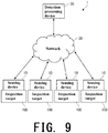
- Fig. 9 is a schematic view showing the detection system according to the third embodiment of the present invention.
- the detection system of the third embodiment will be described by placing emphasis on the points differing from the detection system of the second embodiment, with the same matters being omitted from the description.
- a detection system 1 of the third embodiment is the same as the detection system 1 of the second embodiment except that the plurality of sensing devices 10 are respectively attached to different inspection targets 100.
- the plurality of sensing devices 10 are respectively attached to the different inspection targets 100.
- the detection system 1 with this aspect is especially useful for a case where the plurality of inspection targets 100 having relatively small sizes are arranged so as to be apart from each other.
- a detection method of the present invention with reference to Fig. 10 .
- the detection method of the present invention can be performed with the detection system 1 of the present invention or an arbitrary system having a function equivalent to the function of the detection system 1 of the present invention, the following description will be given with assuming that the detection method of the present invention is performed with the detection system 1.
- Fig. 10 is a flow chart showing the detection method of the present invention.
- a detection method S100 of the present invention is performed at prescribed time intervals (such as every hour, every day, every week and every month).
- the control data is created by the processor 21 of the detection processing device 20 and the created control data is transmitted to the sensing device(s) 10 through the communication unit 27.
- the created and transmitted control data is used for identifying which one of the impulse signal, the swept signal and the random signal should be supplied to the vibration unit 11 from the driving circuit 12 in the sensing device 10.
- the control data is received by the communication unit 14 of the sensing device 10 and transmitted to the driving circuit 12.
- the driving circuit 12 supplies one of the impulse signal, the swept signal and the random signal to the vibration unit 11 according to the control data.
- the vibration unit 11 is driven by the electrical signal supplied from the driving circuit 12 and the vibration unit 11 vibrates. When the vibration unit 11 vibrates, the vibration of the vibration unit 11 is applied to the inspection target 100 and thereby the inspection target 100 vibrates.
- the sensor 13 detects the vibration of the inspection target 100.
- the sensor 13 transmits the vibration information related to the detected vibration of the inspection target 100 to the detection processing device 20 through the communication unit 14.
- the detection processing device 20 receives the vibration information related to the vibration of the inspection target 100 through the communication unit 27.
- the processor 21 of the detection processing device 20 uses the coherence calculating part 25 to calculate the coherence ⁇ 2 between the vibration of the vibration unit 11 of the sensing device 10 and the vibration of the inspection target 100.
- the coherence ⁇ 2 is calculated based on the received vibration information related to the vibration of the inspection target 100 and the vibration information related to the vibration of the vibration unit 11 stored in the storage part 24.
- the vibration information related to the vibration of the vibration unit 11 used in this step corresponds to the vibration caused when the kind of the electrical signal identified by the control data is supplied to the vibration unit 11.
- the vibration information related to the vibration of the vibration unit 11 caused when the impulse signal is supplied to the vibration unit 11 among the vibration information stored in the storage part 24 is used at the step S107.
- the processor 21 determines whether or not the calculated coherence ⁇ 2 is equal to or more than 0.5. In the case of determining that the calculated coherence ⁇ 2 is less than 0.5, the processor 21 determines that the vibration (resonance) of the inspection target 100 is not sufficiently excited by the vibration of the vibration unit 11 and then the process is shifted to a step S108. At the step S108, the processor 21 determines whether or not the number of the events that the coherence ⁇ 2 is less than 0.5 reaches a predetermined number.
- the predetermined number corresponds to the number of the kinds of the electrical signals which can be supplied to the vibration unit 11 from the driving circuit 12. For example, in the case where the driving circuit 12 is configured to be capable of supplying the three kinds of the electrical signals, that is the impulse signal, the swept signal and the random signal, the predetermined number is three.
- the process is shifted to a step S109.
- the processor 21 changes the control data to change the kind of the electrical signal to be supplied to the vibration unit 11 from the driving circuit 12 to the kind which has not yet been supplied to the vibration unit 11. For example, when the impulse signal has been already supplied to the vibration unit 11, the kind of the electrical signal to be supplied to the vibration unit 11 from the driving circuit 12 is changed to the swept signal or the random signal. After that, the process returns to the step S101.
- the process is shifted to a step S110.
- the fact that the number of the events that the coherence ⁇ 2 is less than 0.5 reaches the predetermined number represents that the vibration of the vibration unit 11 caused by all of the electrical signals which can be supplied to the vibration unit 11 from the driving circuit 12 can not sufficiently excite the vibration (resonance) of the inspection target 100. In this case, there is a high possibility that some sort of trouble occurs in the sensing device 10.
- the processor 21 transmits an error message indicating that an error is detected to the user device of the manager or the like for the inspection target 100 through the communication unit 27 and then the process finishes.
- the manager or the like for the inspection target 100 can take an appropriate response.
- the manager or the like can confirm a state of the sensing device 10 or the like.
- the process is shifted to a step Sill.
- the processor 21 uses the resonance frequency calculating part 23 to calculate the resonance frequency f r of the vibration of the inspection target 100 based on the vibration information related to the vibration of the inspection target 100.
- the calculated resonance frequency f r of the vibration of the inspection target 100 is stored in the storage part 24 as the current resonance frequency f r of the vibration of the inspection target 100.
- the processor 21 uses the state change detecting part 26 to compare the current resonance frequency f r of the vibration of the inspection target 100 calculated by the resonance frequency calculating part 23 with the previous resonance frequency f r of the vibration of the inspection target 100 stored in the storage part 24 or the reference resonance frequency f ref stored in the storage part 24 to calculate the difference between the current resonance frequency f r calculated by the resonance frequency calculating part 23 and the previous resonance frequency f r or the reference resonance frequency f ref stored in the storage part 24.
- a step S113 it is determined whether or not the absolute value of the difference between the current resonance frequency f r calculated by the resonance frequency calculating part 23 and the previous resonance frequency f r or the reference resonance frequency f ref stored in the storage part 24, that is, the variation amount of the resonance frequency f r is equal to or more than the predetermined threshold value.
- the process is shifted to a step S114.
- the step S114 it is detected that the state change of the inspection target 100 does not occur and the processor 21 performs the process according to the detection result. After that, the detection method S100 finishes.
- the process is shifted to a step S115.
- the step S115 it is detected that the state change of the inspection target 100 occurs and the processor 21 performs the process according to the detection result. After that, the detection method S100 finishes.
- the detection system 1 and the detection method S100 of the present invention have been described based on the embodiments shown in the accompanying drawings in the above description, the present invention is not limited thereto.
- the configuration of each component of the present invention may be possibly replaced with other arbitrary configurations having equivalent functions. Further, it may be also possible to add other arbitrary components to the configuration of the present invention.
- each component of the detection system 1 may be practiced in the manner of hardware, in the manner of software or in the manner of the combination of hardware and software.
- the detection system 1 of the present invention may contain a plurality of detection processing devices 20.
- Each of the plurality of detection processing devices 20 may communicate with the same sensing device 10 to detect the state change of the inspection target 100 or respectively communicate the different sensing devices 10 to detect the state change of the inspection target 100.
- the number and the kind of the steps of the detection method S100 shown in Fig. 10 are merely provided for the illustration of the present invention, the present invention is not necessarily limited thereto.
- the scope of the present invention contains alternations and changes of the described configuration in which arbitrary steps are added or combined or arbitrary steps are omitted without meaningfully departing from the principle and the spirit of the present invention.
- the detection system and the detection method of the present invention use the VCM (Voice Coil Motor) type vibration unit as an excitation unit for vibrating the inspection target, which includes the coil in which the electrical signal supplied from the driving circuit flows, the spring provided so as to be capable of vibrating and the magnet attached to the spring so as to be apart from the coil.
- VCM Voice Coil Motor
- the vibration unit the excitation unit
- the VCM type vibration unit can cause big vibration with a relatively low input voltage, it is unnecessary to apply a high input voltage to the vibration unit unlike the conventional art using the piezoelectric element.
- the present invention is industrially applicable.
Landscapes
- Physics & Mathematics (AREA)
- General Physics & Mathematics (AREA)
- Health & Medical Sciences (AREA)
- Life Sciences & Earth Sciences (AREA)
- Chemical & Material Sciences (AREA)
- Engineering & Computer Science (AREA)
- General Health & Medical Sciences (AREA)
- Immunology (AREA)
- Pathology (AREA)
- Biochemistry (AREA)
- Analytical Chemistry (AREA)
- Aviation & Aerospace Engineering (AREA)
- Acoustics & Sound (AREA)
- Electromagnetism (AREA)
- Signal Processing (AREA)
- Ceramic Engineering (AREA)
- Food Science & Technology (AREA)
- Medicinal Chemistry (AREA)
- Mechanical Engineering (AREA)
- Optics & Photonics (AREA)
- Measurement Of Mechanical Vibrations Or Ultrasonic Waves (AREA)
- Investigating Or Analyzing Materials By The Use Of Ultrasonic Waves (AREA)
Abstract
Description
- The present invention generally relates to detection systems and detection methods, in particular to a detection system and a detection method for vibrating an inspection target by applying vibration to the inspection target and detecting a state change of the inspection target by analyzing the vibration of the inspection target.
- Generally, in order to detect a state change of an inspection target such as a column of a building structure and a concrete structure, there has been used a method of vibrating the inspection target and then detecting and analyzing vibration of the inspection target. When the state change such as a breakdown and a degradation occurs in the inspection target, a resonance (natural) frequency of the vibration of the inspection target changes. Thus, by analyzing the vibration of the inspection target, it is possible to detect the state change of the inspection target.
- For example,
patent document 1 discloses a frequency measurement device including an excitation unit having an impulse hammer made from a hard material for applying impulse to an inspection target and a sensor for detecting vibration of the inspection target caused by the impulse applied from the excitation unit. When a state of the inspection target changes due to time degradation, breakdown or the like, a mass or a spring constant of the inspection target changes and thus a resonance frequency of the vibration of the inspection target also changes. By using the frequency measurement device disclosed in thepatent document 1, it is possible to detect a change in the resonance frequency of the vibration of the inspection target and thereby detect the state change of the inspection target. - However, for vibrating the inspection target with the excitation unit having the impulse hammer as disclosed in the
patent document 1, it is necessary to make the excitation unit with an impact-resistant material. Generally, such an impact-resistant material is heavy. Further, since it is necessary to apply big impulse to the inspection target for sufficiently vibrating the inspection target, the impulse hammer itself needs to be big and heavy. This causes a problem that a weight and a size of the frequency measurement device increase. - Further, patent document 2 discloses an abnormality detection system including an excitation unit having an impulse hammer made from a hard material or a piezoelectric element (piezo element) for vibrating an inspection target and a sensor for detecting vibration of the inspection target caused by impulse applied from the impulse hammer or vibration of the piezoelectric element. In a case of vibrating the inspection target with the impulse hammer, the same problem as that of the above-mentioned
patent document 1 occurs. On the other hand, in a case of vibrating the inspection target with the piezoelectric element, it is necessary to apply a high input voltage to the piezoelectric element in order to sufficiently vibrate the inspection target. This causes a problem that a power consumption amount required for the abnormality detection system increases. -
- Patent document 1:
JP 2008-157945A - Patent document 2:
JP 2015-111091A - The present invention has been made in view of the conventional problems mentioned above. Accordingly, it is an object of the present invention to achieve simplification, downsizing and power saving of a detection system which can detect a state change of an inspection target by detecting and analyzing vibration of the inspection target caused by vibration applied to the inspection target.
- The above object is achieved by the present inventions defined in the following (1) to (7).
- (1) A detection system for detecting a state change of an inspection target, comprising:
- a sensing device including:
- a vibration unit for applying vibration to the inspection target, the vibration unit attached to the inspection target,
- a driving circuit for supplying an electrical signal to the vibration unit for driving the vibration unit, and
- a sensor for detecting vibration of the inspection target caused by the vibration applied from the vibration unit; and
- a detection processing device for receiving vibration information related to the vibration of the inspection target detected by the sensor from the sensing device and detecting the state change of the inspection target based on the vibration information,
- wherein the vibration unit of the sensing device includes a coil in which the electrical signal supplied from the driving circuit flows, a spring provided so as to be capable of vibrating and a magnet attached to the spring so as to be apart from the coil.
- a sensing device including:
- (2) The detection system according to the above (1), wherein the detection processing device calculates a resonance frequency of the vibration of the inspection target from the vibration information and detects the state change of the inspection target based on a variation amount of the resonance frequency.
- (3) The detection system according to the above (2), wherein the detection processing device includes a storage part for storing the resonance frequency of the vibration of the inspection target, and
wherein the detection processing device compares the calculated resonance frequency of the vibration of the inspection target with the resonance frequency of the vibration of the inspection target stored in the storage part in advance to calculate the variation amount of the resonance frequency and detects the state change of the inspection target when the variation amount of the resonance frequency is equal to or more than a predetermined threshold value. - (4) The detection system according to any one of the above (1) to (3), wherein the driving circuit is configured to supply one of an impulse signal, a swept signal and a random signal to the vibration unit as the electrical signal.
- (5) The detection system according to any one of the above (1) to (4), wherein the sensor is an acceleration sensor attached to the inspection target or a laser sensor provided so as to be apart from the inspection target.
- (6) The detection system according to any one of the above (1) to (5), wherein the detection system contains a plurality of sensing devices, and
wherein the detection processing device receives the vibration information related to the vibration of the inspection target from each of the plurality of sensing devices. - (7) A detection method for detecting a state change of an inspection target, comprising:
- applying vibration to the inspection target by supplying an electrical signal from a driving circuit to a vibration unit attached to the inspection target to drive the vibration unit;
- detecting vibration of the inspection target caused by the vibration applied from the vibration unit by using a sensor; and
- detecting the state change of the inspection target based on the vibration of the inspection target detected by the sensor by using a processor,
- wherein the vibration unit includes a coil in which the electrical signal supplied from the driving circuit flows, a spring provided so as to be capable of vibrating and a magnet attached to the spring so as to be apart from the coil.
- The detection system and the detection method of the present invention use a VCM (Voice Coil Motor) type vibration unit as an excitation unit for vibrating an inspection target, which includes a coil in which an electrical signal supplied from a driving circuit flows, a spring provided so as to be capable of vibrating and a magnet attached to the spring so as to be apart from the coil. Thus, it is unnecessary to constitute the vibration unit (the excitation unit) with an impulse-resistant material unlike the conventional art using the impulse hammer. Further, since the VCM type vibration unit can cause big vibration with a relatively low input voltage, it is unnecessary to apply a high input voltage to the vibration unit unlike the conventional art using the piezoelectric element. Thus, according to the present invention, it is possible to achieve simplification, downsizing and power saving of the detection system.
-
- [
Fig. 1] Fig. 1 is a schematic view showing a detection system according to a first embodiment of the present invention. - [
Fig. 2] Fig. 2 is a perspective view of a vibration unit shown inFig. 1 . - [
Fig. 3] Fig. 3 is an exploded perspective view of the vibration unit shown inFig. 1 . - [
Fig. 4] Fig. 4 is a cross-sectional view of the vibration unit shown inFig. 1 . - [
Fig. 5] Fig. 5 is a view showing examples of vibration of an inspection target caused when one of an impulse signal, a swept signal and a random signal is supplied to the vibration unit shown inFig. 1 . - [
Fig. 6] Fig. 6 is a view showing other examples of the vibration of the inspection target caused when one of the impulse signal, the swept signal and the random signal is supplied to the vibration unit shown inFig. 1 . - [
Fig. 7] Fig. 7 is a view for explaining a change in characteristics of the vibration of the inspection target caused by a change in a mass of the inspection target shown inFig. 1 . - [
Fig. 8] Fig. 8 is a schematic view showing a detection system according to a second embodiment of the present invention. - [
Fig. 9] Fig. 9 is a schematic view showing a detection system according to a third embodiment of the present invention. - [
Fig. 10] Fig. 10 is a flow chart showing a detection method of the present invention. - Hereinafter, description will be given to a detection system and a detection method of the present invention based on preferred embodiments shown in the accompanying drawings. First, a detection system according to a first embodiment of the present invention will be described in detail with reference to
Figs. 1 to 7 . -
Fig. 1 is a schematic view showing the detection system according to the first embodiment of the present invention.Fig. 2 is a perspective view of a vibration unit shown inFig. 1 .Fig. 3 is an exploded perspective view of the vibration unit shown inFig. 1 .Fig. 4 is a cross-sectional view of the vibration unit shown inFig. 1 .Fig. 5 is a view showing examples of vibration of an inspection target caused when one of an impulse signal, a swept signal and a random signal is supplied to the vibration unit shown inFig. 1 .Fig. 6 is a view showing other examples of the vibration of the inspection target caused when one of the impulse signal, the swept signal and the random signal is supplied to the vibration unit shown inFig. 1 .Fig. 7 is a view for explaining a change in characteristics of the vibration of the inspection target caused by a change in a mass of the inspection target shown inFig. 1 . - A
detection system 1 shown inFig. 1 contains asensing device 10 for applying vibration to aninspection target 100 and detecting vibration of theinspection target 100 caused by the applied vibration and adetection processing device 20 for detecting a state change of theinspection target 100 based on vibration information related to the vibration of theinspection target 100 received from thesensing device 10. - The
sensing device 10 has a function of applying the vibration to theinspection target 100 and detecting the vibration of theinspection target 100 caused by the applied vibration. Thesensing device 10 includes avibration unit 11 attached to theinspection target 100 for applying the vibration to theinspection target 100, a drivingcircuit 12 for supplying an electrical signal to thevibration unit 11 for driving thevibration unit 11, asensor 13 for detecting the vibration of theinspection target 100 caused by the vibration applied from thevibration unit 11 and acommunication unit 14 for performing communication with thedetection processing device 20. - The
vibration unit 11 is attached to theinspection target 100 and vibrates according to the electrical signal supplied from the drivingcircuit 12. Thevibration unit 11 is used for applying the vibration to theinspection target 100. As shown inFigs. 2 to 4 , thevibration unit 11 is a VCM (Voice Coil Motor) type vibration unit with a small size (for example, 30 mm height x 30 mm vertical width x 30 mm horizontal width) and constitutes a single resonance system. - The
vibration unit 11 includes acase 111 configured to be attachable to theinspection target 100, acoil 112 fixedly attached on a bottom surface of thecase 111 and in which the electrical signal supplied from the drivingcircuit 12 flows, aspring 113 provided so as to be capable of vibrating with respect to thecase 111 and amagnet assembly 114 attached to thespring 113 and provided so as to be apart from thecoil 112. - The
case 111 is a cylindrical member. Thecase 111 has functions of fixing thevibration unit 11 to a vibrating body and containing each component of thevibration unit 11 therein. Thecase 111 includes acover 111a, abase 111b and acylindrical portion 111c located between thecover 111a and thebase 111b. - Three extending portions are formed on an outer peripheral surface of the
base 111b so as to extend in a radial direction of thebase 111b and through-holes 111d are respectively formed in tip side portions of the three extending portions. Screws (not shown in the drawings) are respectively passed through the through-holes 111d of thebase 111b and respectively screwed with screw holes formed in theinspection target 100. Due to this operation, thebase 111b is fixed to theinspection target 100 and thus thevibration unit 11 can be attached (fixed) to theinspection target 100. By attaching thevibration unit 11 to theinspection target 100, it becomes possible to transmit the vibration of thevibration unit 11 to theinspection target 100, thereby vibrating theinspection target 100. - The
coil 112 has a cylindrical shape and is fixedly provided on thebase 111b. Both end portions (electrical signal supply terminals) of thecoil 112 are connected to the drivingcircuit 12 and thus the electrical signal supplied from the drivingcircuit 12 flows in thecoil 112. Further, as shown inFig. 4 , thecoil 112 is located inside a central opening portion of thespring 113 in a state that thevibration unit 11 has been assembled. - The
spring 113 has a function of holding themagnet assembly 114 so that themagnet assembly 114 can vibrate with respect to thecoil 112. Themagnet assembly 114 is attached to thespring 113. When the electrical signal supplied from the drivingcircuit 12 flows in thecoil 112, driving force for moving themagnet assembly 114 attached to thespring 113 in a vertical direction inFig. 4 occurs. At this time, since themagnet assembly 114 is held by thespring 113 so that themagnet assembly 114 can vibrate with respect to thecoil 112, themagnet assembly 114 can vibrate with respect to thecoil 112. Thespring 113 is not particularly limited as long as it can hold themagnet assembly 114 so that themagnet assembly 114 can vibrate with respect to thecoil 112. For example, a leaf spring, a coil spring, a magnetic spring or the like can be used as thespring 113. Hereinafter, for the illustration of the present invention, the following description will be given with assuming that thespring 113 is the leaf spring as shown inFigs. 3 and4 . - The
spring 113 has a ring shape with the central opening portion. An outer peripheral portion of thespring 113 is held between the base 111b and thecylindrical portion 111c and a central portion of thespring 113 containing the central opening portion can vibrate with respect to thecase 111 in the vertical direction inFig. 4 . Themagnet assembly 114 is attached to the central portion of thespring 113 and thus can vibrate with respect to thecoil 112. - As shown in
Fig. 4 , themagnet assembly 114 includes amagnet holding portion 114a having a cylindrical shape opening toward a lower side inFig. 4 , amagnet 114b fixed on a central lower surface of themagnet holding portion 114a and ayoke 114c attached to a lower surface of themagnet 114b. - As shown in
Fig. 4 , themagnet 114b and theyoke 114c are arranged in a central hollow portion of thecoil 112 so as to be apart from thecoil 112 in the state that thevibration unit 11 has been assembled. When the electrical signal is supplied to thecoil 112 from the drivingcircuit 12, the driving force for moving the magnet assembly 114 (themagnet 114b) in the vertical direction inFig. 4 . Since themagnet assembly 114 is attached to thespring 113 provided so as to be capable of vibrating, themagnet assembly 114 vibrates in the vertical direction. - As described above, when the electrical signal is supplied to the
coil 112 of thevibration unit 11 from the drivingcircuit 12 and flows in thecoil 112, thevibration unit 11 vibrates. A motion equation for representing a motion principle of a single resonance system such as thevibration unit 11 can be represented by the following equation (1). - [Equation 1]

- Where, m is a mass [kg], x(t) is a displacement amount [m] of the magnet assembly 114 (vibrator), Kf is a thrust constant [N/A] of the single resonance system, i(t) is a current [A] flowing in the
coil 112, Ksp is a spring constant [N/m] of thespring 113 and D is a damping coefficient [N/(m/s)] of the single resonance system. - Further, a circuit equation for representing the motion principle of the single resonance system such as the
vibration unit 11 can be represented by the following equation (2). - [Equation 2]

- Where, e(t) is a voltage [V] applied to the
coil 112, R is a resistance [Ω] of thecoil 112, L is an inductance [H] of thecoil 112 and Ke is a counter electromotive force constant [V/(m/s)] of the single resonance system. - From the motion equation and the circuit equation described above, a transfer function G(jω) of the
vibration unit 11 represented by the following equation (3) is derived and this transfer function G(jω) indicates specific responses to the electrical signal supplied from the drivingcircuit 12. - [Equation 3]

- Namely, a characteristic of the vibration of the vibration unit 11 (output of the single resonance system) changes depending on the kind of the electrical signal supplied to the
vibration unit 11 from the driving circuit 12 (input to the single resonance system). For example,Fig. 5 shows examples of the vibration of theinspection target 100 caused when each of an impulse signal, a swept signal and a random signal is supplied to thevibration unit 11 attached to theinspection target 100 for vibrating thevibration unit 11. In this case, a structure constituted of an ABS (Acrylonitrile Butadiene Styrene) resin is used as theinspection target 100. A resonance frequency fr of theinspection target 100 in this case is in the vicinity of 5 kHz. - As shown in
Fig. 5 , in all of the cases where any one of the impulse signal, the swept signal and the random signal is supplied to thevibration unit 11, it can be recognized that an amplitude of the vibration of theinspection target 100 maximizes in the vicinity of 5 kHz which is the resonance frequency fr of theinspection target 100. Thus, in the examples shown inFig. 5 , in all of the cases where any one of the impulse signal, the swept signal and the random signal is supplied to thevibration unit 11, it is possible to detect the resonance frequency fr of the vibration of theinspection target 100. However, in the examples shown inFig. 5 , when the impulse signal is supplied to thevibration unit 11, the amplitude at the resonance frequency fr of theinspection target 100 most conspicuously maximizes. This result indicates the fact that to supply the impulse signal to thevibration unit 11 is most suitable for accurately detecting the resonance frequency fr of theinspection target 100. - On the other hand,
Fig. 6 shows other examples of the vibration of theinspection target 100 caused when each of the impulse signal, the swept signal and the random signal is supplied to thevibration unit 11 attached to theinspection target 100 for vibrating thevibration unit 11. In this case, a structure constituted of a plastic material is used as theinspection target 100. The mass and the spring constant of theinspection target 100 in the examples inFig. 6 are different from the mass and the spring constant of theinspection target 100 in the examples inFig. 5 . The resonance frequency fr of theinspection target 100 in this case ofFig. 6 is in the vicinity of 0.125 kHz. - As shown in
Fig. 6 , when the impulse signal is supplied to thevibration unit 11, the amplitude shows a peak in a frequency range other than 0.125 kHz which is the resonance frequency fr of theinspection target 100. On the other hand, when the swept signal or the random signal is supplied to thevibration unit 11, the amplitude maximizes in the vicinity of 0.125 kHz which is the resonance frequency fr of theinspection target 100. Thus, in the examples shown inFig. 6 , when the impulse signal is supplied to thevibration unit 11, the resonance frequency fr of the vibration of theinspection target 100 cannot be accurately detected. - As described above, the kind of the electrical signal which should be supplied to the
vibration unit 11 from the drivingcircuit 12 changes depending on the mass and/or the spring constant of theinspection target 100. Since the drivingcircuit 12 is configured to supply one of the impulse signal, the swept signal and the random signal to thevibration unit 11 as described later, thesensing device 10 can detect the resonance frequency fr of the vibration of various kinds of inspection targets 100. - As described above, when the
vibration unit 11 attached to theinspection target 100 vibrates, the vibration is applied to theinspection target 100. When the vibration is applied to theinspection target 100 from thevibration unit 11, the vibration of theinspection target 100 is excited. When theinspection target 100 vibrates, theinspection target 100 largely vibrates at the resonance frequency fr derived from the following equation (4) . - [Equation 4]

- Where, m1 is a mass of the
inspection target 100, m2 is a mass of thevibration unit 11 attached to theinspection target 100 and Ksp is a spring constant of theinspection target 100. - As is clear from the above equation (4), the resonance frequency fr of the
inspection target 100 changes depending on the mass m1 and the spring constant Ksp of theinspection target 100. Thus, when a state of theinspection target 100, that is, the mass m1 and the spring constant Ksp change due to some factors such as time elapse and breakdown, the resonance frequency fr of theinspection target 100 also changes. -
Fig. 7 shows an example of a change of the resonance frequency fr of theinspection target 100 when the mass m1 of theinspection target 100 increases from m1a to m1b due to the factors such as time elapse and breakdown. As shown inFig. 7 , when the mass m1 increases from m1a to m1b, a frequency at which the amplitude of the vibration of theinspection target 100 maximizes, that is, the resonance frequency fr is shifted to a lower frequency side. On the other hand, when the mass m1 of theinspection target 100 decreases, the resonance frequency fr of theinspection target 100 is shifted to a higher frequency side. Similarly, when the spring constant Ksp of theinspection target 100 increases, the resonance frequency fr of theinspection target 100 is shifted to the higher frequency side. When the spring constant Ksp of theinspection target 100 decreases, the resonance frequency fr of theinspection target 100 is shifted to the lower frequency side. - As described above, by detecting the change in the resonance frequency fr of the
inspection target 100, it is possible to detect the change in the mass m1 and/or the spring constant Ksp of theinspection target 100, that is the state change of theinspection target 100. - Examples in which the mass m1 of the
inspection target 100 decreases due to the factors such as time elapse and breakdown contain a case where theinspection target 100 is a metallic member made from a metallic material such as an iron. When a part of theinspection target 100 falls due to corrosion or weathering with the lapse of time, the mass m1 of theinspection target 100 decreases. On the other hand, examples in which the mass m1 of theinspection target 100 increases due to the factors such as time elapse and breakdown contain a case where theinspection target 100 is arranged outside. When dusts, dirt, sands, water and/or the like are accumulated on theinspection target 100 with the lapse of time, the mass m1 of theinspection target 100 increases. - Examples in which the spring constant Ksp of the
inspection target 100 changes due to the factors such as time elapse and breakdown contain a case where theinspection target 100 is a structure constituted by coupling a plurality of parts with each other. For example, when bolts or screws for coupling the plurality of parts are loosened or beams among the parts are distorted, the spring constant Ksp of theinspection target 100 changes. Further, in a case where theinspection target 100 is a wheel of a tire of a vehicle, the spring constant Ksp of theinspection target 100 changes due to loosening of the wheel. Further, in a case where theinspection target 100 is a structure made from a concrete and cracks or breaks occur in theinspection target 100 due to some factors such as time elapse and impulse, the spring constant Ksp of theinspection target 100 changes. - As described above, by detecting the change in the resonance frequency fr of the
inspection target 100, it is possible to detect the change in the mass m1 and/or the spring constant Ksp of theinspection target 100, that is the state change of theinspection target 100. Thus, thedetection system 1 can detect a variety of events such as corrosion or weathering of theinspection target 100, increase of an accumulated material on theinspection target 100, loosening of the bolts or the screws of theinspection target 100, distortion of the beam of theinspection target 100, loosening of the wheel of theinspection target 100 and occurrence of the cracks or the breaks of theinspection target 100. - Referring back to
Fig. 1 , the drivingcircuit 12 has a function of supplying the electrical signal to thevibration unit 11 for driving (vibrating) thevibration unit 11. The drivingcircuit 12 is configured to supply at least one of the impulse signal, the swept signal and the random signal to thevibration unit 11 according to control data received from the detectingprocessing device 20 through thecommunication unit 14. - The
sensor 13 has a function of detecting the vibration of theinspection target 100 caused by the vibration applied from thevibration unit 11. Vibration information related to the vibration of theinspection target 100 detected by thesensor 13 is transmitted to thedetection processing device 20 through thecommunication unit 14. For example, the vibration information transmitted to thedetection processing device 20 from thesensor 13 is an acceleration or the like of the vibration (motion) of theinspection target 100. By performing a process such as a Fourier transformation with respect to the vibration information, it is possible to obtain amplitudes (energies) at respective frequencies of the vibration of theinspection target 100. - The
sensor 13 is not particularly limited as long as it can detect the vibration of theinspection target 100. For example, it is possible to use an acceleration sensor attached to theinspection target 100 for detecting an acceleration of the motion of theinspection target 100, a laser sensor provided so as to be apart from theinspection target 100 for irradiating laser to theinspection target 100 and detecting the motion of theinspection target 100 based on the laser reflected from theinspection target 100 or the like as thesensor 13. - The
communication unit 14 has a function of communicating with thedetection processing device 20 to receive the control data from thedetection processing device 20 and transmitting the vibration information related to the vibration of theinspection target 100 detected by thesensor 13 to thedetection processing device 20. In a case where thesensing device 13 is connected to the detectingprocessing device 20 with a wired connection, thecommunication unit 14 performs communication with thedetection processing device 20 with wired communication. In a case where thesensing device 13 is not connected to the detectingprocessing device 20 with the wired connection, thecommunication unit 14 performs communication with thedetection processing device 20 with a wireless communication technology such as an NFC (Near Field Radio Communication), a Wi-Fi and a Bluetooth (registered trademark). - In this regard, power supply to each component of the
sensing device 10 may be achieved by an internal power source such as a battery build in thesensing device 10 or an external power source arranged outside thesensing device 10 and connected to thesensing device 10 with a power supply wire. - The
detection processing device 20 has functions of transmitting the control data to thesensing device 10, receiving the vibration information related to the vibration of theinspection target 100 detected by thesensor 13 from thesensing device 10 and detecting the state change of theinspection target 100 based on the received vibration information. - The
detection processing device 20 may be practiced as a stand-alone device or practiced in an arbitrary computing device such as a desktop computer, a laptop computer, a notebook computer, a workstation, a tablet computer, a mobile phone, a smart phone, a PDA and a wearable device. - The
detection processing device 20 includes at least oneprocessor 21 for performing control for thedetection processing device 20, amemory 22 storing data, programs, modules and the like required for performing the control of thedetection processing device 20, a resonancefrequency calculating part 23 for calculating the resonance frequency fr of the vibration of theinspection target 100 based on the received vibration information, astorage part 24 for storing the resonance frequency fr calculated by the resonancefrequency calculating part 23 and/or a reference resonance frequency fref of the vibration of theinspection target 100, acoherence calculating part 25 for calculating a coherence γ2 between the vibration of thevibration unit 11 of thesensing device 10 and the vibration of theinspection target 100, a statechange detecting part 26 for detecting the state change of theinspection target 100 by comparing the resonance frequency fr of the vibration of theinspection target 100 calculated by the resonancefrequency calculating part 23 with the reference resonance frequency fref stored in thestorage part 24 or a previous resonance frequency fr of the vibration of theinspection target 100 stored in thestorage part 24, acommunication unit 27 for performing communication with thesensing device 10 and adata bus 28 for transmitting and receiving data between respective components of thedetection processing device 20. - The
processor 21 performs, transmits and receives a variety of data or a variety of instructions with each component through thedata bus 28 for performing the control of thedetection processing device 20. Further, theprocessor 21 can provide desired functions by using each component of thedetection processing device 20. For example, theprocessor 21 can use the resonancefrequency calculating part 23 to calculate the resonance frequency fr of the vibration of theinspection target 100 based on the received vibration information, use thecoherence calculating part 25 to calculate the coherence γ2 between the vibration of thevibration unit 11 of thesensing device 10 and the vibration of theinspection target 100 and use the statechange detecting part 26 to detect the state change of theinspection target 100. - Further, the
processor 21 transmits the control data to thesensing device 10 through thecommunication unit 27 at prescribed time intervals (such as every hour, every day, every week and every week) for allowing thesensing device 10 to measure the vibration of theinspection target 100. The control data transmitted from theprocessor 21 is used for identifying which one of the impulse signal, the swept signal and the random signal should be supplied to the vibratingunit 11 from the drivingcircuit 12 of thesensing device 10. The drivingcircuit 12 receiving the control data supplies one of the impulse signal, the swept signal and the random signal to thevibration unit 11 according to the control data for vibrating thevibration unit 11. - The
processor 21 is one or more operation units such as microprocessors, microcomputers, microcontrollers, digital signal processors (DSPs), central processing units (CPUs), memory control units (MCUs), graphic processing units (GPUs), state machines, logic circuitries, application specific integrated circuits (ASICs) and combinations thereof that can perform operational processes for manipulating signals or the like based on computer-readable instructions. Among other capabilities, theprocessor 21 is configured to fetch computer-readable instructions (such as data, programs and modules) stored in thememory 22 and execute signal control and signal manipulation. - The
memory 22 is one or more removable or non-removable computer-readable media including volatile memories (such as RAMs, SRAMs and DRAMs), non-volatile memories (such as ROMs, EPROMs, EEPROMs, flash memories, hard disks, optical discs, CD-ROMs, digital versatile discs (DVDs), magnetic cassettes, magnetic tapes and magnetic disks) and combinations thereof. - The resonance
frequency calculating part 23 has a function of calculating the resonance frequency fr of the vibration of theinspection target 100 based on the vibration information received from thesensing device 10 through thecommunication unit 27. Specifically, the resonancefrequency calculating part 23 performs the process such as a Fourier transformation with respect to the received vibration information to calculate the amplitudes (energies) at the respective frequencies of the vibration of theinspection target 100 as shown inFig. 7 . The resonancefrequency calculating part 23 identifies a frequency having the largest amplitude (energy) as the resonance frequency fr of the vibration of theinspection target 100. - The
storage part 24 is an arbitrary non-volatile storage media (such as a hard disk and a flash memory) for storing the resonance frequency fr calculated by the resonancefrequency calculating part 23 and/or the reference resonance frequency fref of the vibration of theinspection target 100. The reference resonance frequency fref of the vibration of theinspection target 100 is a resonance frequency fr of the vibration of theinspection target 100 when theinspection target 100 is in a normal state. The reference resonance frequency fref is measured and stored in thestorage part 24 before thedetection system 1 starts to operate. Further, the resonance frequency fr of the vibration of theinspection target 100 calculated by the resonancefrequency calculating part 23 is stored instorage part 24 as accumulated data every time when the resonancefrequency calculating part 23 calculates the resonance frequency fr. Such accumulated data can be used for tracking the state change of theinspection target 100 in time series to provide information useful for maintenance and inspection of theinspection target 100. Further, such accumulated data may be transmitted to a manager or the like for theinspection target 100 as a report at prescribed time intervals (such as every hour, every day, every week and every month). - The
storage part 24 further stores vibration information related to the vibration of thevibration unit 11 obtained in advance. The vibration information related to the vibration of thevibration unit 11 contains at least vibration information related to the vibration of thevibration unit 11 caused when the drivingcircuit 12 supplies the impulse signal to thevibration unit 11, vibration information related to the vibration of thevibration unit 11 caused when the drivingcircuit 12 supplies the swept signal to thevibration unit 11 and vibration information related to the vibration of thevibration unit 11 caused when the drivingcircuit 12 supplies the random signal to thevibration unit 11. The vibration information related to the vibration of thevibration unit 11 as described above is used for allowing thecoherence calculating part 25 described later to calculate the coherence γ2 between the vibration of thevibration unit 11 of thesensing device 10 and the vibration of theinspection target 100. - The
coherence calculating part 25 has a function of calculating the coherence γ2 between the vibration of thevibration unit 11 of thesensing device 10 and the vibration of theinspection target 100 based on the vibration information related to the vibration of thevibration unit 11 of thesensing device 10 stored in thestorage part 24 and the vibration information related to the vibration of theinspection target 100 received from thesensing device 10. Specifically, thecoherence calculating part 25 uses the following equation (5) to calculate a coherence value between the vibration of thevibration unit 11 of thesensing device 10 and the vibration of theinspection target 100. - [Equation 5]

- Where, Wxx is a power spectrum of an input vibration, that is a power spectrum of the vibration of the
vibration unit 11. Wxx is calculated from the vibration information related to the vibration of thevibration unit 11 of thesensing device 10 stored in thestorage part 24. Wyy is a power spectrum of an output vibration, that is a power spectrum of the vibration of theinspection target 100. Wxy is a cross spectrum between the vibration of thevibration unit 11 and the vibration of theinspection target 100. - The coherence γ2 described above represents a strength of a relationship between the input vibration and the output vibration. By referring to the value of the coherence γ2 described above, it is possible to determine whether or not resonance of the
inspection target 100 is excited by the vibration of thevibration unit 11. As the coherence γ2 approaches 1, this result indicates that the resonance of theinspection target 100 is efficiently excited by the vibration of thevibration unit 11. As the coherence γ2 approaches 0, this result indicates that the resonance of theinspection target 100 is not excited by the vibration of thevibration unit 11. - When the coherence γ2 described above becomes less than 0.5, this result indicates that the
inspection target 100 is not sufficiently resonated (vibrated). As described above, by referring to the coherence γ2 calculated by thecoherence calculating part 25, it is possible to determine whether or not theinspection target 100 is sufficiently vibrated. Theprocessor 21 changes the control data depending on the value of the coherence γ2 calculated by thecoherence calculating part 25. For example, if the coherence γ2 is less than 0.5 when the impulse signal is supplied from the drivingcircuit 12 to thevibration unit 11, theprocessor 21 interprets that the resonance of theinspection target 100 is not excited by supplying the impulse signal to thevibration unit 11. After that, theprocessor 21 changes the control data so that the swept signal or the random signal is supplied to thevibration unit 11 from the drivingcircuit 12 and transmits the changed control data to the drivingcircuit 12 through thecommunication unit 27. - The state
change detecting part 26 has a function of detecting the state change of theinspection target 100 by comparing the resonance frequency fr of the vibration of theinspection target 100 calculated by the resonancefrequency calculating part 23 with the reference resonance frequency fref stored in thestorage part 24 or the previous resonance frequency fr of the vibration of theinspection target 100 stored in thestorage part 24. Specifically, the statechange detecting part 26 calculates a difference between the resonance frequency fr of the vibration of theinspection target 100 calculated by the resonancefrequency calculating part 23 and the reference resonance frequency fref or the previous resonance frequency fr of the vibration of theinspection target 100 stored in thestorage part 24 and then determines whether or not an absolute value of the calculated difference, that is, a variation amount of the resonance frequency fr is equal to or more than a predetermined threshold value. The predetermined value is appropriately set depending on some factors such as a size, a constituent material, a shape or the like of theinspection target 100. - In a case of determining that the absolute value of the calculated difference (the variation amount of the resonance frequency fr) is equal to or more than the predetermined threshold value, the state
change detecting part 26 detects the state change of theinspection target 100. On the other hand, in a case of determining that the absolute value of the calculated difference (the variation amount of the resonance frequency fr) is less than the predetermined threshold value, the statechange detecting part 26 detects that the state change of theinspection target 100 does not occur. After that, theprocessor 21 performs a process according to a result of the detection by the statechange detecting part 26. For example, theprocessor 21 performs a process for transmitting a message indicating that the state change of theinspection target 100 is detected to a user device (such as a desktop computer, a laptop computer, a notebook computer, a workstation, a tablet computer, a mobile phone, a smart phone, a PDA and a wearable device) of the manager or the like for theinspection target 100 when the state change of theinspection target 100 is detected. With this configuration, the manager or the like for theinspection target 100 can know occurrence of the state change of theinspection target 100 and take an appropriate response. - The
communication unit 27 has a function of performing the communication with thesensing device 10 to transmit the control data to thesensing device 10 and receive the vibration information related to the vibration of theinspection target 100 detected by thesensor 13 of thesensing device 10 from thesensing device 10. Further, thecommunication unit 27 has a function of performing communication with the user device of the manager for theinspection target 100. The manager for theinspection target 100 performs the communication with thedetection processing device 20 through thecommunication unit 27 to change various setting of the detection processing device 20 (such as setting of time intervals (every day, every week or the like) with which the detection process should be performed). Further, thedetection processing device 20 can transmit the above-mentioned accumulated data or the message to the user device of the manager for theinspection target 100 through thecommunication unit 27. As is the case of thecommunication unit 14, thecommunication unit 27 can use a variety of wired communication and wireless communication to perform the communication with thesensing device 10 or the user device of the manager for theinspection target 100. Further, thecommunication unit 27 may use a variety of wired communication and wireless communication to perform communication with a variety of external devices other than thesensing device 10 or the user device of the manager for theinspection target 100. - In this regard, power supply to each component of the
detection processing device 20 may be achieved by an internal power source such as a battery build in thedetection processing device 20 or an external power source arranged outside thedetection processing device 20 and connected to thedetection processing device 20 with a power supply wire. - As described above, the
detection system 1 of thepresent invention 1 uses the VCMtype vibration unit 11 including thecoil 112 in which the electrical signal supplied from the drivingcircuit 12 for applying the vibration to theinspection target 100 flows, thespring 113 provided so as to be capable of vibrating and themagnet 114b attached to thespring 113 so as to be apart from thecoil 112. Thus, it is unnecessary to constitute thevibration unit 11 with an impulse-resistant material unlike the conventional art using the impulse hammer. Further, since the VCMtype vibration unit 11 can cause big vibration with a relatively low input voltage, it is unnecessary to apply a high input voltage to thevibration unit 11 unlike the conventional art using the piezoelectric element. Thus, according to the present invention, it is possible to achieve simplification, downsizing and power saving of thedetection system 1. - In this regard, although the
sensing device 10 and thedetection processing device 20 are described as separated devices respectively contained in different cases in this embodiment, the present invention is not limited thereto. For example, a unit for providing functions equivalent to the functions of thesensing device 10 and a unit for providing functions equivalent to thedetection processing device 20 may be contained in one case and practiced as one device. - Next, description will be given to a detection system according to a second embodiment of the present invention with reference to
Fig. 8. Fig. 8 is a schematic view showing the detection system according to the second embodiment of the present invention. Hereinafter, the detection system of the second embodiment will be described by placing emphasis on the points differing from the detection system of the first embodiment, with the same matters being omitted from the description. - A
detection system 1 of the second embodiment is the same as thedetection system 1 of the first embodiment except that thedetection system 1 contains a plurality ofsensing devices 10 and thedetection processing device 20 are communicatively connected to the plurality ofsensing devices 10 through anetwork 30. - The
detection processing device 20 in this embodiment may be a stand-alone device connected to thenetwork 30 or practiced in a server connected to thenetwork 30. - The plurality of
sensing devices 10 in this embodiment are attached to oneinspection target 100. The plurality ofsensing devices 10 are communicatively connected to thedetection processing device 20 through thenetwork 30. - The
network 30 is a variety of networks such as an intranet, a local area network (LAN), a wide area network (WAN), Internet and combinations thereof. Further, thenetwork 30 may be a dedicated network or a shared network. The shared network represents an association of the different types of networks that use a variety of protocols (such as HTTP, TCP/IP and WAP) to communicate with each other. Further thenetwork 30 may include a variety of network devices, including routers, bridges, servers, computing devices, storage devices and the like. - The
detection processing device 20 receives the vibration information of the vibration of theinspection target 100 from the plurality ofsensing devices 10 through thenetwork 30. With this configuration, it becomes possible to detect the presence or absence of the state changes of locations of theinspection target 100 to which the plurality ofsensing devices 10 are respectively attached and detect the presence or absence of the state change of the whole of theinspection target 100. Thedetection system 1 with the above-mentioned aspect is especially useful to a case where theinspection target 100 is a large size structure such as a bridge and a tunnel. - Next, description will be given to a detection system according to a third embodiment of the present invention with reference to
Fig. 9. Fig. 9 is a schematic view showing the detection system according to the third embodiment of the present invention. Hereinafter, the detection system of the third embodiment will be described by placing emphasis on the points differing from the detection system of the second embodiment, with the same matters being omitted from the description. - A
detection system 1 of the third embodiment is the same as thedetection system 1 of the second embodiment except that the plurality ofsensing devices 10 are respectively attached to different inspection targets 100. - In the
detection system 1 of this embodiment, the plurality ofsensing devices 10 are respectively attached to the different inspection targets 100. Thedetection system 1 with this aspect is especially useful for a case where the plurality of inspection targets 100 having relatively small sizes are arranged so as to be apart from each other. - Next, description will be given to a detection method of the present invention with reference to
Fig. 10 . In this regard, although the detection method of the present invention can be performed with thedetection system 1 of the present invention or an arbitrary system having a function equivalent to the function of thedetection system 1 of the present invention, the following description will be given with assuming that the detection method of the present invention is performed with thedetection system 1.Fig. 10 is a flow chart showing the detection method of the present invention. - A detection method S100 of the present invention is performed at prescribed time intervals (such as every hour, every day, every week and every month). At a step S101, the control data is created by the
processor 21 of thedetection processing device 20 and the created control data is transmitted to the sensing device(s) 10 through thecommunication unit 27. The created and transmitted control data is used for identifying which one of the impulse signal, the swept signal and the random signal should be supplied to thevibration unit 11 from the drivingcircuit 12 in thesensing device 10. - At a step S102, the control data is received by the
communication unit 14 of thesensing device 10 and transmitted to the drivingcircuit 12. The drivingcircuit 12 supplies one of the impulse signal, the swept signal and the random signal to thevibration unit 11 according to the control data. Next, at a step S103, thevibration unit 11 is driven by the electrical signal supplied from the drivingcircuit 12 and thevibration unit 11 vibrates. When thevibration unit 11 vibrates, the vibration of thevibration unit 11 is applied to theinspection target 100 and thereby theinspection target 100 vibrates. - Next, at a step S104, the
sensor 13 detects the vibration of theinspection target 100. At a step S105, thesensor 13 transmits the vibration information related to the detected vibration of theinspection target 100 to thedetection processing device 20 through thecommunication unit 14. As a step S106, thedetection processing device 20 receives the vibration information related to the vibration of theinspection target 100 through thecommunication unit 27. - At a step S107, the
processor 21 of thedetection processing device 20 uses thecoherence calculating part 25 to calculate the coherence γ2 between the vibration of thevibration unit 11 of thesensing device 10 and the vibration of theinspection target 100. The coherence γ2 is calculated based on the received vibration information related to the vibration of theinspection target 100 and the vibration information related to the vibration of thevibration unit 11 stored in thestorage part 24. In this regard, the vibration information related to the vibration of thevibration unit 11 used in this step corresponds to the vibration caused when the kind of the electrical signal identified by the control data is supplied to thevibration unit 11. For example, when the kind of the electrical signal identified by the control data is the impulse signal, the vibration information related to the vibration of thevibration unit 11 caused when the impulse signal is supplied to thevibration unit 11 among the vibration information stored in thestorage part 24 is used at the step S107. - The
processor 21 determines whether or not the calculated coherence γ2 is equal to or more than 0.5. In the case of determining that the calculated coherence γ2 is less than 0.5, theprocessor 21 determines that the vibration (resonance) of theinspection target 100 is not sufficiently excited by the vibration of thevibration unit 11 and then the process is shifted to a step S108. At the step S108, theprocessor 21 determines whether or not the number of the events that the coherence γ2 is less than 0.5 reaches a predetermined number. Here, the predetermined number corresponds to the number of the kinds of the electrical signals which can be supplied to thevibration unit 11 from the drivingcircuit 12. For example, in the case where the drivingcircuit 12 is configured to be capable of supplying the three kinds of the electrical signals, that is the impulse signal, the swept signal and the random signal, the predetermined number is three. - In a case of determining that the number of the events that the coherence γ2 is less than 0.5 does not reach the predetermined number, the process is shifted to a step S109. At the step S109, the
processor 21 changes the control data to change the kind of the electrical signal to be supplied to thevibration unit 11 from the drivingcircuit 12 to the kind which has not yet been supplied to thevibration unit 11. For example, when the impulse signal has been already supplied to thevibration unit 11, the kind of the electrical signal to be supplied to thevibration unit 11 from the drivingcircuit 12 is changed to the swept signal or the random signal. After that, the process returns to the step S101. - On the other hand, in a case of determining that the number of the events that the coherence γ2 is less than 0.5 reaches the predetermined number at the step S108, the process is shifted to a step S110. The fact that the number of the events that the coherence γ2 is less than 0.5 reaches the predetermined number represents that the vibration of the
vibration unit 11 caused by all of the electrical signals which can be supplied to thevibration unit 11 from the drivingcircuit 12 can not sufficiently excite the vibration (resonance) of theinspection target 100. In this case, there is a high possibility that some sort of trouble occurs in thesensing device 10. For example, it is expected that some sort of trouble that thesensing unit 11 is detached from theinspection target 100, thevibration unit 11 or thesensor 13 gets out of order or sufficient power is not supplied to thesensing device 10 occurs. Thus, at a step S110, theprocessor 21 transmits an error message indicating that an error is detected to the user device of the manager or the like for theinspection target 100 through thecommunication unit 27 and then the process finishes. By transmitting such an error message to the user device of the manager or the like for theinspection target 100, the manager or the like for theinspection target 100 can take an appropriate response. For example, the manager or the like can confirm a state of thesensing device 10 or the like. - On the other hand, in a case of determining that the coherence γ2 is equal to or more than 0.5, the process is shifted to a step Sill. At the step Sill, the
processor 21 uses the resonancefrequency calculating part 23 to calculate the resonance frequency fr of the vibration of theinspection target 100 based on the vibration information related to the vibration of theinspection target 100. The calculated resonance frequency fr of the vibration of theinspection target 100 is stored in thestorage part 24 as the current resonance frequency fr of the vibration of theinspection target 100. - At a step S112, the
processor 21 uses the statechange detecting part 26 to compare the current resonance frequency fr of the vibration of theinspection target 100 calculated by the resonancefrequency calculating part 23 with the previous resonance frequency fr of the vibration of theinspection target 100 stored in thestorage part 24 or the reference resonance frequency fref stored in thestorage part 24 to calculate the difference between the current resonance frequency fr calculated by the resonancefrequency calculating part 23 and the previous resonance frequency fr or the reference resonance frequency fref stored in thestorage part 24. - At a step S113, it is determined whether or not the absolute value of the difference between the current resonance frequency fr calculated by the resonance
frequency calculating part 23 and the previous resonance frequency fr or the reference resonance frequency fref stored in thestorage part 24, that is, the variation amount of the resonance frequency fr is equal to or more than the predetermined threshold value. In a case of determining that the absolute value of the calculated difference (the variation amount of the resonance frequency fr) is less than the predetermined threshold value at the step S113, the process is shifted to a step S114. At the step S114, it is detected that the state change of theinspection target 100 does not occur and theprocessor 21 performs the process according to the detection result. After that, the detection method S100 finishes. - On the other hand, in a case of determining that the absolute value of the calculated difference (the variation amount of the resonance frequency fr) is equal to or more than the predetermined threshold value at the step S113, the process is shifted to a step S115. At the step S115, it is detected that the state change of the
inspection target 100 occurs and theprocessor 21 performs the process according to the detection result. After that, the detection method S100 finishes. - Although the
detection system 1 and the detection method S100 of the present invention have been described based on the embodiments shown in the accompanying drawings in the above description, the present invention is not limited thereto. The configuration of each component of the present invention may be possibly replaced with other arbitrary configurations having equivalent functions. Further, it may be also possible to add other arbitrary components to the configuration of the present invention. - For example, the number and the kind of the components of the
detection system 1 shown inFig. 1 are merely provided for the illustration of the present invention, the present invention is not necessarily limited thereto. The scope of the present invention contains alternations and changes of the described configuration in which arbitrary components are added or combined or arbitrary components are omitted without meaningfully departing from the principle and the spirit of the present invention. Further, each component of thedetection system 1 may be practiced in the manner of hardware, in the manner of software or in the manner of the combination of hardware and software. - Further, although the number of the
detection processing devices 20 shown in each of the first embodiment to the third embodiment is one, the present invention is not limited thereto. Thedetection system 1 of the present invention may contain a plurality ofdetection processing devices 20. Each of the plurality ofdetection processing devices 20 may communicate with thesame sensing device 10 to detect the state change of theinspection target 100 or respectively communicate thedifferent sensing devices 10 to detect the state change of theinspection target 100. - Further, the number and the kind of the steps of the detection method S100 shown in
Fig. 10 are merely provided for the illustration of the present invention, the present invention is not necessarily limited thereto. The scope of the present invention contains alternations and changes of the described configuration in which arbitrary steps are added or combined or arbitrary steps are omitted without meaningfully departing from the principle and the spirit of the present invention. - The detection system and the detection method of the present invention use the VCM (Voice Coil Motor) type vibration unit as an excitation unit for vibrating the inspection target, which includes the coil in which the electrical signal supplied from the driving circuit flows, the spring provided so as to be capable of vibrating and the magnet attached to the spring so as to be apart from the coil. Thus, it is unnecessary to constitute the vibration unit (the excitation unit) with an impulse-resistant material unlike the conventional art using the impulse hammer. Further, since the VCM type vibration unit can cause big vibration with a relatively low input voltage, it is unnecessary to apply a high input voltage to the vibration unit unlike the conventional art using the piezoelectric element. Thus, according to the present invention, it is possible to achieve simplification, downsizing and power saving of the detection system. For the reasons stated above, the present invention is industrially applicable.
Claims (7)
- A detection system for detecting a state change of an inspection target, comprising:a sensing device including:a vibration unit for applying vibration to the inspection target, the vibration unit attached to the inspection target,a driving circuit for supplying an electrical signal to the vibration unit for driving the vibration unit, anda sensor for detecting vibration of the inspection target caused by the vibration applied from the vibration unit; anda detection processing device for receiving vibration information related to the vibration of the inspection target detected by the sensor from the sensing device and detecting the state change of the inspection target based on the vibration information,wherein the vibration unit of the sensing device includes a coil in which the electrical signal supplied from the driving circuit flows, a spring provided so as to be capable of vibrating and a magnet attached to the spring so as to be apart from the coil.
- The detection system as claimed in claim 1, wherein the detection processing device calculates a resonance frequency of the vibration of the inspection target from the vibration information and detects the state change of the inspection target based on a variation amount of the resonance frequency.
- The detection system as claimed in claim 2, wherein the detection processing device includes a storage part for storing the resonance frequency of the vibration of the inspection target, and
wherein the detection processing device compares the calculated resonance frequency of the vibration of the inspection target with the resonance frequency of the vibration of the inspection target stored in the storage part in advance to calculate the variation amount of the resonance frequency and detects the state change of the inspection target when the variation amount of the resonance frequency is equal to or more than a predetermined threshold value. - The detection system as claimed in any one of claims 1 to 3, wherein the driving circuit is configured to supply one of an impulse signal, a swept signal and a random signal to the vibration unit as the electrical signal.
- The detection system as claimed in any one of claims 1 to 4, wherein the sensor is an acceleration sensor attached to the inspection target or a laser sensor provided so as to be apart from the inspection target.
- The detection system as claimed in any one of claims 1 to 5, wherein the detection system contains a plurality of sensing devices, and
wherein the detection processing device receives the vibration information related to the vibration of the inspection target from each of the plurality of sensing devices. - A detection method for detecting a state change of an inspection target, comprising:applying vibration to the inspection target by supplying an electrical signal from a driving circuit to a vibration unit attached to the inspection target to drive the vibration unit;detecting vibration of the inspection target caused by the vibration applied from the vibration unit by using a sensor; anddetecting the state change of the inspection target based on the vibration of the inspection target detected by the sensor by using a processor,wherein the vibration unit includes a coil in which the electrical signal supplied from the driving circuit flows, a spring provided so as to be capable of vibrating and a magnet attached to the spring so as to be apart from the coil.
Applications Claiming Priority (2)
| Application Number | Priority Date | Filing Date | Title |
|---|---|---|---|
| JP2017090620 | 2017-04-28 | ||
| PCT/JP2018/013498 WO2018198665A1 (en) | 2017-04-28 | 2018-03-29 | Detection system and detection method |
Publications (3)
| Publication Number | Publication Date |
|---|---|
| EP3617699A1 true EP3617699A1 (en) | 2020-03-04 |
| EP3617699A4 EP3617699A4 (en) | 2021-01-06 |
| EP3617699B1 EP3617699B1 (en) | 2024-10-23 |
Family
ID=63919115
Family Applications (1)
| Application Number | Title | Priority Date | Filing Date |
|---|---|---|---|
| EP18791366.0A Active EP3617699B1 (en) | 2017-04-28 | 2018-03-29 | Detection system and detection method |
Country Status (5)
| Country | Link |
|---|---|
| US (2) | US11249052B2 (en) |
| EP (1) | EP3617699B1 (en) |
| JP (1) | JP7177355B2 (en) |
| CN (1) | CN110573874B (en) |
| WO (1) | WO2018198665A1 (en) |
Families Citing this family (6)
| Publication number | Priority date | Publication date | Assignee | Title |
|---|---|---|---|---|
| JP7152100B2 (en) * | 2018-03-16 | 2022-10-12 | ミツミ電機株式会社 | Sensing system, sensing method, and non-transitory computer readable medium |
| US10703625B1 (en) * | 2019-03-29 | 2020-07-07 | Industrial Technology Research Institute | Microelectromechanical system (MEMS) apparatus with adjustable spring |
| CN110631790B (en) * | 2019-09-25 | 2022-01-25 | 歌尔科技有限公司 | Wearable device and detection method thereof |
| CN112665710A (en) * | 2020-12-21 | 2021-04-16 | 陕西宝光集团有限公司 | Method and device for detecting running state of equipment, electronic equipment and storage medium |
| CN113640301B (en) * | 2021-08-03 | 2024-02-09 | 江苏省特种设备安全监督检验研究院 | Bolt detection method for special equipment |
| JP2024139229A (en) | 2023-03-27 | 2024-10-09 | セイコーエプソン株式会社 | Projector device, projector, support device, abnormality determination device, and abnormality determination method |
Family Cites Families (37)
| Publication number | Priority date | Publication date | Assignee | Title |
|---|---|---|---|---|
| DE1130631B (en) | 1960-01-22 | 1962-05-30 | Schenck Gmbh Carl | Oscillating system with continuously variable frequency and amplitude, especially for vibrating tables, dynamic material testing machines and the like like |
| GB8309030D0 (en) | 1983-03-31 | 1983-05-11 | Cawley P | Testing of structures by impact |
| US5048320A (en) | 1986-08-28 | 1991-09-17 | Mitsui Engineering & Shipbuilding Co., Ltd. | Method and apparatus for impact-type inspection of structures |
| JPH01219555A (en) | 1988-02-26 | 1989-09-01 | Mitsubishi Petrochem Co Ltd | impact tester |
| US5003824A (en) * | 1989-12-26 | 1991-04-02 | Matsushita Electric Industrial Co., Ltd. | Vibration/acceleration sensor |
| JP2845583B2 (en) * | 1990-07-10 | 1999-01-13 | 株式会社資生堂 | Method and apparatus for measuring mechanical properties of living body surface and structure of vibrator with built-in sensor |
| US5533381A (en) * | 1994-06-10 | 1996-07-09 | Seale; Joseph B. | Conversion of liquid volume, density, and viscosity to frequency signals |
| JP3144454B2 (en) * | 1994-11-29 | 2001-03-12 | 株式会社大林組 | Apparatus and method for determining degree of concrete hardening |
| US5847817A (en) * | 1997-01-14 | 1998-12-08 | Mcdonnell Douglas Corporation | Method for extending range and sensitivity of a fiber optic micro-doppler ladar system and apparatus therefor |
| JP2000314730A (en) | 1999-05-06 | 2000-11-14 | Non-Destructive Inspection Co Ltd | Vibration fatigue controle method for material |
| JP3352652B2 (en) | 1999-08-20 | 2002-12-03 | 松下電器産業株式会社 | Fruit and vegetable sorting method and fruit and vegetable sorting device |
| US6488117B1 (en) * | 2001-08-24 | 2002-12-03 | Thomas E. Owen | Vertical-force vibrator seismic wave source |
| JP2004085412A (en) | 2002-08-28 | 2004-03-18 | Koden Electronics Co Ltd | Apparatus for inspecting vibration inside solid |
| GB2406907B (en) * | 2003-10-10 | 2006-11-15 | Optoplan As | Active coherence reduction for interferometer interrogation |
| JP2007198996A (en) * | 2006-01-30 | 2007-08-09 | Toray Eng Co Ltd | Resonance inspection device and resonance inspection method |
| US7578191B2 (en) | 2006-12-22 | 2009-08-25 | General Electric Company | Reactor jet pump sensing line frequency measurement |
| IL184868A0 (en) * | 2007-07-26 | 2008-03-20 | Univ Bar Ilan | Motion detection system and method |
| GB2446685B (en) * | 2007-11-27 | 2009-04-01 | Perpetuum Ltd | An electromechanical generator for converting mechanical vibrational energy into electrical energy |
| JP2009186423A (en) | 2008-02-08 | 2009-08-20 | Ntn Corp | Inspection method and inspection unit |
| JP5272441B2 (en) * | 2008-02-20 | 2013-08-28 | ミツミ電機株式会社 | Vibration generator |
| US8214178B2 (en) * | 2008-06-04 | 2012-07-03 | Vibration Technologies, Llc | Method and system for optimizing the vibrational characteristics of a structure |
| JP2010104864A (en) * | 2008-10-28 | 2010-05-13 | Sanyo Electric Co Ltd | Reciprocating vibration generator |
| JP2011169446A (en) * | 2010-02-22 | 2011-09-01 | Mitsumi Electric Co Ltd | Plate spring and lens driving device |
| US8645101B2 (en) * | 2011-02-10 | 2014-02-04 | Siemens Energy, Inc. | Method for monitoring the condition of a vibration sensor |
| WO2012177659A2 (en) * | 2011-06-20 | 2012-12-27 | Vibrant Corporation | Part evaluation system/method using both resonance and surface vibration data |
| JP5874505B2 (en) * | 2012-04-10 | 2016-03-02 | オムロン株式会社 | Vibration energy detection device, vibration energy detection system |
| JP6036143B2 (en) * | 2012-10-11 | 2016-11-30 | ミツミ電機株式会社 | Power generator |
| US9964503B2 (en) | 2012-10-19 | 2018-05-08 | Resodyn Corporation | Methods and systems for detecting flaws in an object |
| FR2997495B1 (en) * | 2012-10-30 | 2015-07-24 | Eurocopter France | METHOD FOR MONITORING VIBRATORY SENSORS |
| US9097604B2 (en) * | 2012-11-30 | 2015-08-04 | The Boeing Company | Electrodynamic modal test impactor system and method |
| JP2015111091A (en) | 2013-11-06 | 2015-06-18 | パナソニック株式会社 | Sensor device and abnormality detection system |
| EP2921842B1 (en) | 2014-03-18 | 2020-06-24 | Russenberger Prüfmaschinen AG | Resonance testing machine |
| JP6284272B2 (en) | 2014-09-04 | 2018-02-28 | 鈴木 基行 | Nondestructive inspection equipment |
| US10024756B2 (en) * | 2014-10-28 | 2018-07-17 | Embraer S.A. | Method and system for structural health monitoring with frequency synchronization |
| WO2016117160A1 (en) * | 2015-01-20 | 2016-07-28 | オリンパス株式会社 | Scanning endoscope device |
| WO2017145850A1 (en) * | 2016-02-22 | 2017-08-31 | 日本電気株式会社 | Inspection device, inspection method, and recording medium on which inspection program has been recorded |
| US10660523B2 (en) * | 2017-07-07 | 2020-05-26 | Hideo Ando | Light-source unit, measurement apparatus, near-infrared microscopic apparatus, optical detection method, imaging method, calculation method, functional bio-related substance, state management method, and manufacturing method |
-
2018
- 2018-03-29 CN CN201880028182.XA patent/CN110573874B/en active Active
- 2018-03-29 JP JP2019515177A patent/JP7177355B2/en active Active
- 2018-03-29 US US16/609,195 patent/US11249052B2/en active Active
- 2018-03-29 WO PCT/JP2018/013498 patent/WO2018198665A1/en not_active Ceased
- 2018-03-29 EP EP18791366.0A patent/EP3617699B1/en active Active
-
2021
- 2021-12-30 US US17/646,643 patent/US12247951B2/en active Active
Also Published As
| Publication number | Publication date |
|---|---|
| CN110573874A (en) | 2019-12-13 |
| US20220120716A1 (en) | 2022-04-21 |
| US12247951B2 (en) | 2025-03-11 |
| CN110573874B (en) | 2023-03-14 |
| US11249052B2 (en) | 2022-02-15 |
| WO2018198665A1 (en) | 2018-11-01 |
| EP3617699B1 (en) | 2024-10-23 |
| JP7177355B2 (en) | 2022-11-24 |
| EP3617699A4 (en) | 2021-01-06 |
| JPWO2018198665A1 (en) | 2020-03-12 |
| US20200057029A1 (en) | 2020-02-20 |
Similar Documents
| Publication | Publication Date | Title |
|---|---|---|
| EP3617699B1 (en) | Detection system and detection method | |
| JP7262050B2 (en) | Power tool system, power tool, and power tool management method | |
| CN103582607A (en) | Calibration of MEMS sensor | |
| US11815415B2 (en) | Reference signal compensation for magnetostrictive sensor | |
| SE540205C2 (en) | System and method for assessing the efficiency of a drilling process | |
| JP6710653B2 (en) | Sensor adhesion state determination system, sensor adhesion state determination device, and sensor adhesion state determination method | |
| JP2019152538A (en) | Fastening bolt fastening torque specifying device and fastening torque specifying method | |
| JP2009030994A5 (en) | ||
| JP2008128665A (en) | Vibration test method, vibration test auxiliary device, and vibration test system | |
| EP3444581A1 (en) | Improved gap compensation for magnetostrictive torque sensors | |
| US9927460B2 (en) | Calibrating rotational accelerometers | |
| US6389897B1 (en) | Vibratory gyroscopes and method for manufacturing the same | |
| CN110596784B (en) | Testing device and testing method of earth sound sensing probe and readable storage medium | |
| JP6806329B2 (en) | Inspection equipment and inspection method | |
| US20150211959A1 (en) | Systems and methods for determining oscillations of a tire | |
| CN111255437A (en) | Detection device and method | |
| KR20200045980A (en) | Method and system for direct estimation of exact power in real-time | |
| CN110632679A (en) | Signal calibration method, test device and computer readable storage medium | |
| CN106104205A (en) | For optimizing the method for turn-on time of Coriolis gyro and being applicable to this Coriolis gyro | |
| JPH11148876A (en) | Bolt tightening force inspection device | |
| JP7369535B2 (en) | Impact test method | |
| CN109850713A (en) | A kind of elevator detection method, device, system, equipment and storage medium | |
| JPS59187132A (en) | Vibroisolation controlling device | |
| EP4383034A1 (en) | Enhanced transducer fault detection | |
| JP7488865B2 (en) | Bolt looseness estimation device, bolt looseness estimation method, and bolt looseness estimation program |
Legal Events
| Date | Code | Title | Description |
|---|---|---|---|
| STAA | Information on the status of an ep patent application or granted ep patent |
Free format text: STATUS: THE INTERNATIONAL PUBLICATION HAS BEEN MADE |
|
| PUAI | Public reference made under article 153(3) epc to a published international application that has entered the european phase |
Free format text: ORIGINAL CODE: 0009012 |
|
| STAA | Information on the status of an ep patent application or granted ep patent |
Free format text: STATUS: REQUEST FOR EXAMINATION WAS MADE |
|
| 17P | Request for examination filed |
Effective date: 20191008 |
|
| AK | Designated contracting states |
Kind code of ref document: A1 Designated state(s): AL AT BE BG CH CY CZ DE DK EE ES FI FR GB GR HR HU IE IS IT LI LT LU LV MC MK MT NL NO PL PT RO RS SE SI SK SM TR |
|
| AX | Request for extension of the european patent |
Extension state: BA ME |
|
| DAV | Request for validation of the european patent (deleted) | ||
| DAX | Request for extension of the european patent (deleted) | ||
| A4 | Supplementary search report drawn up and despatched |
Effective date: 20201203 |
|
| RIC1 | Information provided on ipc code assigned before grant |
Ipc: B06B 1/04 20060101ALI20201127BHEP Ipc: G01N 29/44 20060101ALI20201127BHEP Ipc: G01N 33/38 20060101ALI20201127BHEP Ipc: G01M 7/00 20060101ALI20201127BHEP Ipc: G01N 29/34 20060101ALI20201127BHEP Ipc: G01N 29/04 20060101ALI20201127BHEP Ipc: G01H 1/14 20060101ALI20201127BHEP Ipc: G01N 3/32 20060101ALI20201127BHEP Ipc: G01N 29/12 20060101AFI20201127BHEP |
|
| STAA | Information on the status of an ep patent application or granted ep patent |
Free format text: STATUS: EXAMINATION IS IN PROGRESS |
|
| 17Q | First examination report despatched |
Effective date: 20230125 |
|
| GRAP | Despatch of communication of intention to grant a patent |
Free format text: ORIGINAL CODE: EPIDOSNIGR1 |
|
| STAA | Information on the status of an ep patent application or granted ep patent |
Free format text: STATUS: GRANT OF PATENT IS INTENDED |
|
| INTG | Intention to grant announced |
Effective date: 20240722 |
|
| GRAS | Grant fee paid |
Free format text: ORIGINAL CODE: EPIDOSNIGR3 |
|
| GRAA | (expected) grant |
Free format text: ORIGINAL CODE: 0009210 |
|
| STAA | Information on the status of an ep patent application or granted ep patent |
Free format text: STATUS: THE PATENT HAS BEEN GRANTED |
|
| AK | Designated contracting states |
Kind code of ref document: B1 Designated state(s): AL AT BE BG CH CY CZ DE DK EE ES FI FR GB GR HR HU IE IS IT LI LT LU LV MC MK MT NL NO PL PT RO RS SE SI SK SM TR |
|
| REG | Reference to a national code |
Ref country code: GB Ref legal event code: FG4D |
|
| REG | Reference to a national code |
Ref country code: CH Ref legal event code: EP |
|
| REG | Reference to a national code |
Ref country code: DE Ref legal event code: R096 Ref document number: 602018075769 Country of ref document: DE |
|
| REG | Reference to a national code |
Ref country code: IE Ref legal event code: FG4D |
|
| P01 | Opt-out of the competence of the unified patent court (upc) registered |
Free format text: CASE NUMBER: APP_60548/2024 Effective date: 20241111 |
|
| REG | Reference to a national code |
Ref country code: LT Ref legal event code: MG9D |
|
| REG | Reference to a national code |
Ref country code: NL Ref legal event code: MP Effective date: 20241023 |
|
| REG | Reference to a national code |
Ref country code: AT Ref legal event code: MK05 Ref document number: 1735231 Country of ref document: AT Kind code of ref document: T Effective date: 20241023 |
|
| PG25 | Lapsed in a contracting state [announced via postgrant information from national office to epo] |
Ref country code: NL Free format text: LAPSE BECAUSE OF FAILURE TO SUBMIT A TRANSLATION OF THE DESCRIPTION OR TO PAY THE FEE WITHIN THE PRESCRIBED TIME-LIMIT Effective date: 20241023 |
|
| PG25 | Lapsed in a contracting state [announced via postgrant information from national office to epo] |
Ref country code: NL Free format text: LAPSE BECAUSE OF FAILURE TO SUBMIT A TRANSLATION OF THE DESCRIPTION OR TO PAY THE FEE WITHIN THE PRESCRIBED TIME-LIMIT Effective date: 20241023 |
|
| PG25 | Lapsed in a contracting state [announced via postgrant information from national office to epo] |
Ref country code: PT Free format text: LAPSE BECAUSE OF FAILURE TO SUBMIT A TRANSLATION OF THE DESCRIPTION OR TO PAY THE FEE WITHIN THE PRESCRIBED TIME-LIMIT Effective date: 20250224 Ref country code: IS Free format text: LAPSE BECAUSE OF FAILURE TO SUBMIT A TRANSLATION OF THE DESCRIPTION OR TO PAY THE FEE WITHIN THE PRESCRIBED TIME-LIMIT Effective date: 20250223 Ref country code: HR Free format text: LAPSE BECAUSE OF FAILURE TO SUBMIT A TRANSLATION OF THE DESCRIPTION OR TO PAY THE FEE WITHIN THE PRESCRIBED TIME-LIMIT Effective date: 20241023 |
|
| PG25 | Lapsed in a contracting state [announced via postgrant information from national office to epo] |
Ref country code: FI Free format text: LAPSE BECAUSE OF FAILURE TO SUBMIT A TRANSLATION OF THE DESCRIPTION OR TO PAY THE FEE WITHIN THE PRESCRIBED TIME-LIMIT Effective date: 20241023 |
|
| PG25 | Lapsed in a contracting state [announced via postgrant information from national office to epo] |
Ref country code: BG Free format text: LAPSE BECAUSE OF FAILURE TO SUBMIT A TRANSLATION OF THE DESCRIPTION OR TO PAY THE FEE WITHIN THE PRESCRIBED TIME-LIMIT Effective date: 20241023 |
|
| PG25 | Lapsed in a contracting state [announced via postgrant information from national office to epo] |
Ref country code: ES Free format text: LAPSE BECAUSE OF FAILURE TO SUBMIT A TRANSLATION OF THE DESCRIPTION OR TO PAY THE FEE WITHIN THE PRESCRIBED TIME-LIMIT Effective date: 20241023 |
|
| PG25 | Lapsed in a contracting state [announced via postgrant information from national office to epo] |
Ref country code: NO Free format text: LAPSE BECAUSE OF FAILURE TO SUBMIT A TRANSLATION OF THE DESCRIPTION OR TO PAY THE FEE WITHIN THE PRESCRIBED TIME-LIMIT Effective date: 20250123 |
|
| PG25 | Lapsed in a contracting state [announced via postgrant information from national office to epo] |
Ref country code: AT Free format text: LAPSE BECAUSE OF FAILURE TO SUBMIT A TRANSLATION OF THE DESCRIPTION OR TO PAY THE FEE WITHIN THE PRESCRIBED TIME-LIMIT Effective date: 20241023 Ref country code: LV Free format text: LAPSE BECAUSE OF FAILURE TO SUBMIT A TRANSLATION OF THE DESCRIPTION OR TO PAY THE FEE WITHIN THE PRESCRIBED TIME-LIMIT Effective date: 20241023 Ref country code: GR Free format text: LAPSE BECAUSE OF FAILURE TO SUBMIT A TRANSLATION OF THE DESCRIPTION OR TO PAY THE FEE WITHIN THE PRESCRIBED TIME-LIMIT Effective date: 20250124 |
|
| PG25 | Lapsed in a contracting state [announced via postgrant information from national office to epo] |
Ref country code: PL Free format text: LAPSE BECAUSE OF FAILURE TO SUBMIT A TRANSLATION OF THE DESCRIPTION OR TO PAY THE FEE WITHIN THE PRESCRIBED TIME-LIMIT Effective date: 20241023 |
|
| PG25 | Lapsed in a contracting state [announced via postgrant information from national office to epo] |
Ref country code: RS Free format text: LAPSE BECAUSE OF FAILURE TO SUBMIT A TRANSLATION OF THE DESCRIPTION OR TO PAY THE FEE WITHIN THE PRESCRIBED TIME-LIMIT Effective date: 20250123 |
|
| PG25 | Lapsed in a contracting state [announced via postgrant information from national office to epo] |
Ref country code: SM Free format text: LAPSE BECAUSE OF FAILURE TO SUBMIT A TRANSLATION OF THE DESCRIPTION OR TO PAY THE FEE WITHIN THE PRESCRIBED TIME-LIMIT Effective date: 20241023 |
|
| PG25 | Lapsed in a contracting state [announced via postgrant information from national office to epo] |
Ref country code: DK Free format text: LAPSE BECAUSE OF FAILURE TO SUBMIT A TRANSLATION OF THE DESCRIPTION OR TO PAY THE FEE WITHIN THE PRESCRIBED TIME-LIMIT Effective date: 20241023 |
|
| PG25 | Lapsed in a contracting state [announced via postgrant information from national office to epo] |
Ref country code: EE Free format text: LAPSE BECAUSE OF FAILURE TO SUBMIT A TRANSLATION OF THE DESCRIPTION OR TO PAY THE FEE WITHIN THE PRESCRIBED TIME-LIMIT Effective date: 20241023 |
|
| PG25 | Lapsed in a contracting state [announced via postgrant information from national office to epo] |
Ref country code: RO Free format text: LAPSE BECAUSE OF FAILURE TO SUBMIT A TRANSLATION OF THE DESCRIPTION OR TO PAY THE FEE WITHIN THE PRESCRIBED TIME-LIMIT Effective date: 20241023 |
|
| REG | Reference to a national code |
Ref country code: DE Ref legal event code: R097 Ref document number: 602018075769 Country of ref document: DE |
|
| PG25 | Lapsed in a contracting state [announced via postgrant information from national office to epo] |
Ref country code: SK Free format text: LAPSE BECAUSE OF FAILURE TO SUBMIT A TRANSLATION OF THE DESCRIPTION OR TO PAY THE FEE WITHIN THE PRESCRIBED TIME-LIMIT Effective date: 20241023 |
|
| PG25 | Lapsed in a contracting state [announced via postgrant information from national office to epo] |
Ref country code: CZ Free format text: LAPSE BECAUSE OF FAILURE TO SUBMIT A TRANSLATION OF THE DESCRIPTION OR TO PAY THE FEE WITHIN THE PRESCRIBED TIME-LIMIT Effective date: 20241023 |
|
| PG25 | Lapsed in a contracting state [announced via postgrant information from national office to epo] |
Ref country code: IT Free format text: LAPSE BECAUSE OF FAILURE TO SUBMIT A TRANSLATION OF THE DESCRIPTION OR TO PAY THE FEE WITHIN THE PRESCRIBED TIME-LIMIT Effective date: 20241023 |
|
| PLBE | No opposition filed within time limit |
Free format text: ORIGINAL CODE: 0009261 |
|
| STAA | Information on the status of an ep patent application or granted ep patent |
Free format text: STATUS: NO OPPOSITION FILED WITHIN TIME LIMIT |
|
| PG25 | Lapsed in a contracting state [announced via postgrant information from national office to epo] |
Ref country code: SE Free format text: LAPSE BECAUSE OF FAILURE TO SUBMIT A TRANSLATION OF THE DESCRIPTION OR TO PAY THE FEE WITHIN THE PRESCRIBED TIME-LIMIT Effective date: 20241023 |
|
| 26N | No opposition filed |
Effective date: 20250724 |
|
| PG25 | Lapsed in a contracting state [announced via postgrant information from national office to epo] |
Ref country code: MC Free format text: LAPSE BECAUSE OF FAILURE TO SUBMIT A TRANSLATION OF THE DESCRIPTION OR TO PAY THE FEE WITHIN THE PRESCRIBED TIME-LIMIT Effective date: 20241023 |
|
| REG | Reference to a national code |
Ref country code: CH Ref legal event code: H13 Free format text: ST27 STATUS EVENT CODE: U-0-0-H10-H13 (AS PROVIDED BY THE NATIONAL OFFICE) Effective date: 20251023 |
|
| PG25 | Lapsed in a contracting state [announced via postgrant information from national office to epo] |
Ref country code: LU Free format text: LAPSE BECAUSE OF NON-PAYMENT OF DUE FEES Effective date: 20250329 |
|
| REG | Reference to a national code |
Ref country code: BE Ref legal event code: MM Effective date: 20250331 |
|
| PG25 | Lapsed in a contracting state [announced via postgrant information from national office to epo] |
Ref country code: BE Free format text: LAPSE BECAUSE OF NON-PAYMENT OF DUE FEES Effective date: 20250331 |
|
| PG25 | Lapsed in a contracting state [announced via postgrant information from national office to epo] |
Ref country code: CH Free format text: LAPSE BECAUSE OF NON-PAYMENT OF DUE FEES Effective date: 20250331 |
|
| PG25 | Lapsed in a contracting state [announced via postgrant information from national office to epo] |
Ref country code: IE Free format text: LAPSE BECAUSE OF NON-PAYMENT OF DUE FEES Effective date: 20250329 |
|
| PGFP | Annual fee paid to national office [announced via postgrant information from national office to epo] |
Ref country code: GB Payment date: 20260324 Year of fee payment: 9 |
|
| PGFP | Annual fee paid to national office [announced via postgrant information from national office to epo] |
Ref country code: DE Payment date: 20260319 Year of fee payment: 9 |
|
| PGFP | Annual fee paid to national office [announced via postgrant information from national office to epo] |
Ref country code: FR Payment date: 20260320 Year of fee payment: 9 |