EP3617692B1 - System for protecting an optical system - Google Patents
System for protecting an optical system Download PDFInfo
- Publication number
- EP3617692B1 EP3617692B1 EP19191019.9A EP19191019A EP3617692B1 EP 3617692 B1 EP3617692 B1 EP 3617692B1 EP 19191019 A EP19191019 A EP 19191019A EP 3617692 B1 EP3617692 B1 EP 3617692B1
- Authority
- EP
- European Patent Office
- Prior art keywords
- opening
- cover
- optical system
- optical
- air flow
- Prior art date
- Legal status (The legal status is an assumption and is not a legal conclusion. Google has not performed a legal analysis and makes no representation as to the accuracy of the status listed.)
- Active
Links
Images




Classifications
-
- G—PHYSICS
- G01—MEASURING; TESTING
- G01N—INVESTIGATING OR ANALYSING MATERIALS BY DETERMINING THEIR CHEMICAL OR PHYSICAL PROPERTIES
- G01N21/00—Investigating or analysing materials by the use of optical means, i.e. using sub-millimetre waves, infrared, visible or ultraviolet light
- G01N21/01—Arrangements or apparatus for facilitating the optical investigation
- G01N21/15—Preventing contamination of the components of the optical system or obstruction of the light path
-
- G—PHYSICS
- G02—OPTICS
- G02B—OPTICAL ELEMENTS, SYSTEMS OR APPARATUS
- G02B27/00—Optical systems or apparatus not provided for by any of the groups G02B1/00 - G02B26/00, G02B30/00
- G02B27/0006—Optical systems or apparatus not provided for by any of the groups G02B1/00 - G02B26/00, G02B30/00 with means to keep optical surfaces clean, e.g. by preventing or removing dirt, stains, contamination, condensation
-
- G—PHYSICS
- G02—OPTICS
- G02B—OPTICAL ELEMENTS, SYSTEMS OR APPARATUS
- G02B6/00—Light guides; Structural details of arrangements comprising light guides and other optical elements, e.g. couplings
- G02B6/24—Coupling light guides
- G02B6/36—Mechanical coupling means
- G02B6/38—Mechanical coupling means having fibre to fibre mating means
- G02B6/3807—Dismountable connectors, i.e. comprising plugs
- G02B6/3873—Connectors using guide surfaces for aligning ferrule ends, e.g. tubes, sleeves, V-grooves, rods, pins, balls
-
- G—PHYSICS
- G01—MEASURING; TESTING
- G01N—INVESTIGATING OR ANALYSING MATERIALS BY DETERMINING THEIR CHEMICAL OR PHYSICAL PROPERTIES
- G01N21/00—Investigating or analysing materials by the use of optical means, i.e. using sub-millimetre waves, infrared, visible or ultraviolet light
- G01N21/01—Arrangements or apparatus for facilitating the optical investigation
- G01N21/15—Preventing contamination of the components of the optical system or obstruction of the light path
- G01N2021/151—Gas blown
-
- G—PHYSICS
- G02—OPTICS
- G02B—OPTICAL ELEMENTS, SYSTEMS OR APPARATUS
- G02B6/00—Light guides; Structural details of arrangements comprising light guides and other optical elements, e.g. couplings
- G02B6/0001—Light guides; Structural details of arrangements comprising light guides and other optical elements, e.g. couplings specially adapted for lighting devices or systems
- G02B6/0005—Light guides; Structural details of arrangements comprising light guides and other optical elements, e.g. couplings specially adapted for lighting devices or systems the light guides being of the fibre type
- G02B6/001—Light guides; Structural details of arrangements comprising light guides and other optical elements, e.g. couplings specially adapted for lighting devices or systems the light guides being of the fibre type the light being emitted along at least a portion of the lateral surface of the fibre
-
- G—PHYSICS
- G08—SIGNALLING
- G08G—TRAFFIC CONTROL SYSTEMS
- G08G1/00—Traffic control systems for road vehicles
- G08G1/09—Arrangements for giving variable traffic instructions
- G08G1/0962—Arrangements for giving variable traffic instructions having an indicator mounted inside the vehicle, e.g. giving voice messages
- G08G1/0967—Systems involving transmission of highway information, e.g. weather, speed limits
Definitions
- the present invention relates to a system for protecting an optical system.
- Optical systems which are located in an outdoor environment may be exposed to contamination, for example caused by water, ice or other material particles.
- contamination for example caused by water, ice or other material particles.
- Examples of an optical system are a camera and a measurement system such as a road condition monitoring system.
- Known road condition monitoring systems are capable of providing data relating to real-time roadway condition information.
- the systems are related to monitoring and maintenance of transportation infrastructure, such as highways, city streets, back roads and runways.
- the systems may be also used to allow evaluation and analysis to improve repair response time and facilitate accurate prediction of roadway breakdown.
- the road condition monitoring systems are typically attached to vehicles and used during movement of the vehicles. Normally, the road condition monitoring systems are used at least during the winter season. Various parameters such as a water layer thickness, an ice layer thickness, a surface temperature, and a dew point temperature may be measured or evaluated by the road condition monitoring systems.
- the optical measurement systems in particular the lenses of such road condition monitoring systems, are typically protected in order to avoid contamination which would influence the measurement result.
- a tube may be coupled to the optical measurement system as a protector, for instance.
- Such a solution is e.g. known from the Teconer Road Condition Monitor RCM411 TM .
- GB 1 039 955 A discloses a system for protecting an optical system consisting of an inner and an outer part for guiding an incoming airflow there between.
- a system for protecting an optical system comprising a hollow first part having at least one first opening, a hollow second part arranged at least partially within the first part, and a coupling section configured to be coupled to the optical system, wherein the system is configured to guide at least a part of an incoming air flow from the at least one first opening along a flow channel between an inner surface of the first part and an outer surface of the second part.
- the system is made of thermoplastic polyurethane (TPU) or thermoplastic elastomers (TPE).
- a system for protecting an optical system is provided.
- contamination of the optical system can be eliminated or at least reduced.
- the incoming air can enter the system through the at least one opening in the outer hollow part of the system.
- at least a part of the air flow is guided between the inner surface of the outer hollow part and the outer surface of the inner hollow part.
- the air flow is then directed substantially downwards at the end of the inner hollow part.
- creation of a vortex within the inner hollow part can be avoided or at least the vorticity within the inner hollow part can be reduced. Therefore, also contamination of a window or lens of the optical system can be eliminated or at least reduced. Consequently, the inner hollow part of the system according to the present invention can be relatively short, and thus the system for protecting the optical system can be very compact.
- the system comprises at least one protrusion in the form of a perimeter wall protruding from a cover having at least one opening into a cavity of the inner hollow profile.
- Both the cover and the at least one protrusion reduce the risk of contamination of the external optical system to be located on the other side of the cover.
- the cover reduces the exposed surface area of a lens or window of the optical system.
- the protrusion further prevents drops or liquids from entering the at least one opening through the cover, and thus further reduces the risk of contamination of the external optical system.
- the system according to the invention being made of thermoplastic polyurethane or thermoplastic elastomer, it is made of flexible material.
- the system can vibrate relatively heavily when being in use, for example when being attached to a moving vehicle. Particles, which are adhered to the system, for example to the hollow inner part and the cover, may be disengaged from the system due to the vibrations.
- the system according to certain embodiments of the present invention also improves traffic safety due to maintaining accurate measurement results of a road condition, as the system reduces contamination of a window or lens of an optical road condition measurement system over time.
- the system is further capable of being manufactured in industrial scale.
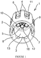
- FIGURE 1 a schematic perspective view of a system 1 in accordance with at least some embodiments of the present invention is illustrated.
- the system 1 comprises a hollow first part 2 having a plurality of first openings 4 and a hollow second part 3 arranged at least partially within the first part 2.
- the hollow first part 2, i.e. the outer part, and the hollow second part 3, i.e. the inner part, are connected to each other.
- a first end 11 of the second part 3 is connected to the first part 2.
- the first and second parts 2, 3 may be connected to each other via a further third part.
- the third part is represented by a coupling section 6 which is configured to be coupled to an external optical system (not shown).
- the optical system may be, for example, arranged in a housing (not shown).
- Examples of an optical system are a camera and a measurement system such as a road condition monitoring system.
- the system 1 according to the present invention is configured to guide at least a part of an incoming air flow from at least one of the openings 4 along a flow channel 7 between an inner surface 8 of the first part 2 and an outer surface 9 of the second part 3.
- the incoming air flow may be e.g. caused by wind or by movement of the system 1, for example when being attached to a moving vehicle.
- contamination of the optical system can be eliminated or at least reduced.
- the incoming air can enter the system 1 through the first openings 4 in the outer hollow part 2. Subsequently, at least a part of the air flow is guided downwards between the inner surface 8 of the outer hollow part 2 and the outer surface 9 of the inner hollow part 3. The air flow is then orientated substantially downwards at the second end 18 of the inner hollow part 3.
- creation of a vortex within the cavity 13 of the inner hollow part 3 can be avoided or at least the vorticity within the cavity 13 of the inner hollow part 3 can be reduced.
- the inner hollow part 3 can be therefore relatively short, and thus the system 1 for protecting the optical system can be very compact.
- the second part 3 further comprises a cover 5 having four second openings 10.
- three of the four second openings 10 are arranged for providing the capability of laser beams of an optical measurement system to pass the cover 5.
- a receiver (not shown) may be arranged behind the fourth of the four second openings 10.
- the cover 5 is arranged at the first end 11 of the second part 3.
- the cover 5 may also be a part of the coupling section 6. The cover 5 reduces the surface area, which is exposed to contamination, of a window or lens of the optical system.
- protrusions 12 further extend from the cover 5 into the cavity 13 of the second part 3.
- the protrusions 12 are in the form of a perimeter wall around each of the four second openings 10, respectively. Drops or liquid flowing along the cover 5 therefore cannot enter the second openings 10.
- the protrusions also somewhat protect a window or lens of an optical system from droplets moving upwards in the air.
- FIGURE 2 a schematic side view of a system 1 in accordance with at least some embodiments of the present invention is illustrated.
- the central axis 17 of the system 1 is typically orientated vertically or substantially vertically.
- the term "vertically” means vertically in the established sense of the word to refer to the normal of the Earth's surface.
- An incoming air flow A is typically orientated perpendicular or substantially perpendicular to the central axis 17.
- the incoming air flow may be e.g. caused by wind or by movement of the system 1.
- the system 1 may comprise a plurality of first openings 4 through the first part 2, for example eight first openings 4.
- the first openings 4 may be, for example, arranged circumferentially around the first part 2.
- the incoming air flow A can enter the system 1 through at least one of the first openings 4.
- the system 1 is always well positioned regardless of the direction of the incoming air flow A.
- the second part 3, which is arranged within the first part 2, is shorter than the first part 2.
- the lower part of the first part 2 overlaps with a second end (not visible) of the second part 3. Consequently, the lower part of the first part 2 serves locally as some sort of flow protector from the incoming air flow A for the second part 3, particularly for the entrance into the second part 3.
- the coupling section 6 further comprises a wedge shaped portion 14 for each first opening 4.
- the wedge shaped portions 14 are dimensioned such that the incoming air flow A is directed downwards in the region of the first openings 4/coupling section 6. After having entered the system 1 through at least one first opening 4, the air flow A is at least partially guided downwards in a flow channel between the first part 2 and the second part 3.
- the velocity of the flow in the flow channel is less than the velocity of the incoming air flow A.
- the flow is directed substantially downwards at the second end (lower end) of the second part 3.
- the velocity of the flow at the second end (lower end) of the second part 3 is less than the velocity of the incoming air flow A.
- the incoming air flow A is guided within the system 1 such that creation of a vortex within the cavity of the second part 3, which is typically in the form of a tube, can be avoided or such that the vorticity within the cavity of the second part 3 can be at least reduced.
- the incoming air flow A is used to reduce contamination of a window or lens of an optical system.
- No moving parts are comprised by the system 1. Especially, no moving parts are required for creating an air flow.
- FIGURE 3 a schematic top view of a system 1 in accordance with at least some embodiments of the present invention is illustrated.
- Four second openings 10 through the cover 5 of the system 1 are shown.
- the three second openings 10 are of identical size and shape.
- Each of the aforementioned three second openings 10 is arranged for transmission of a respective laser beam.
- the fourth of the second openings 10 is arranged for receiving an optical spectrum by a receiver of an optical measurement system.
- other embodiments may comprise only one second opening or any other integer number of second openings.
- the size and shape of the second openings 10 may be identical or different.
- the shape of the second openings 10 may be, for example, circular, elliptical, triangular, rectangular or polygonal.
- a coupling section 6 comprising two indentations 15 is illustrated.
- the indentations 15 are configured to interact with respective counterparts comprised by a housing of the external optical measurement system.
- parts of the housing of the external optical system can be inserted into the indentations 15.
- the coupling section 6 may comprise any other integer number of indentations 15.
- the shape and size of the indentations may differ from the shown indentations 15.
- FIGURE 5 and FIGURE 8 a locking system comprised by the coupling section 6 is additionally shown.
- FIGURE 4 a schematic bottom view of a system 1 in accordance with at least some embodiments of the present invention is illustrated.
- Four first openings 10 through the cover 5 of the system 1 are shown.
- four corresponding protrusions 12 in the form of perimeter walls extend from the cover 5 into the cavity 13 of the second part 3.
- the protrusions 12 and the cover 5 may be made of one single piece, for instance.
- the protrusions 12 may be attached to the cover 5, for example O-shaped rings may be attached to the cover 5 by use of adhesive.
- the protrusions 12 and the cover 5 may be of identical or different material.
- the function of the protrusions 12 is to prevent drops or liquid from flowing along the cover 5 into the at least one second opening 10, and thus prevent contamination of a window or lens of an optical system positioned behind the cover 5.
- the protrusions 12 may also somewhat protect a window or lens of an optical system from droplets moving upwards in the air through the cavity 13 of the second part 3.
- Other words for such protrusions may be a seal, a lip or a sealing lip, for instance.
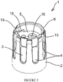
- FIGURE 5 another schematic perspective view of a system 1 in accordance with at least some embodiments of the present invention is illustrated.
- the system 1 comprises a first part 2, a second part 3 and a third part in the form of a coupling section 6. All parts 2, 3, 6 are made from one single piece.
- materials of the system 1 are TPU or TPE.
- the coupling section 6 comprises two indentations 15, wherein each indentation 15 is configured to receive a corresponding part of a housing of an optical system. Additionally, a locking section 16 adjacent to each indentation 15 is comprised by the coupling section 6.
- the locking section may comprise a bayonet catch, for instance.
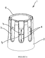
- FIGURE 6 a further schematic perspective view of a system 1 in accordance with at least some embodiments of the present invention is illustrated.
- the first part 2 comprises a plurality of first openings 4.
- the first openings 4 may be substantially of rectangular or elliptical shape, for instance.
- a first (maximum) length l 1 of a first opening 4 is in the range between 40 mm - 80 mm, for example about 55 mm.
- a second (maximum) length l 2 is in the range between 10 mm - 30 mm, for example about 20 mm.
- the first length l 1 is arranged parallel or substantially parallel to the central axis of the system 1.
- the second length l 2 i.e.
- a (maximum) width of the respective first opening 4 is perpendicular to the first length l 1 .
- the present invention is not limited to the aforementioned dimensions.
- Other embodiments may have at least one first opening 4 having a different shape or having other dimensions.
- the at least one first opening 4 is designed to provide an entry into the system 1 for an incoming air flow. At least a part of the air flow is then guided from the entry along a flow channel formed between the first part 2 and the second part 3 of the system 1.
- FIGURE 7 a yet further schematic perspective view of a system 1 in accordance with at least some embodiments of the present invention is illustrated.
- the first part 2 and the second part 3 are both in the form of a tube.
- a length of the first part 2 is greater than a length of the second part 3.
- the second part 3 having a diameter, which is smaller than a diameter of the first part 2 is completely arranged within the first part 2.
- the first part 2, the second part 3, and the third part, i.e. the coupling section 6, are formed from one single piece.
- the system 1 is made from several pieces which are fixedly attached to each other.
- first part 2 and the second part 3 may each be a metal tube. Both the first part 2 and the second part 3 may be attached to the coupling section 6 in order to form the system 1. Both the first part 2 and the second part 3 may be tubes made from metal or plastic material, but this is not claimed.
- FIGURE 8 an even further schematic perspective view of a system 1 in accordance with at least some embodiments of the present invention is illustrated.
- Embodiments of the present invention find industrial application in protection of an optical road condition measurement system.
Landscapes
- Physics & Mathematics (AREA)
- General Physics & Mathematics (AREA)
- Optics & Photonics (AREA)
- Health & Medical Sciences (AREA)
- Life Sciences & Earth Sciences (AREA)
- Chemical & Material Sciences (AREA)
- Analytical Chemistry (AREA)
- Biochemistry (AREA)
- General Health & Medical Sciences (AREA)
- Immunology (AREA)
- Pathology (AREA)
- Lens Barrels (AREA)
Description
- The present invention relates to a system for protecting an optical system.
- Optical systems which are located in an outdoor environment may be exposed to contamination, for example caused by water, ice or other material particles. Examples of an optical system are a camera and a measurement system such as a road condition monitoring system.
- Known road condition monitoring systems are capable of providing data relating to real-time roadway condition information. The systems are related to monitoring and maintenance of transportation infrastructure, such as highways, city streets, back roads and runways. The systems may be also used to allow evaluation and analysis to improve repair response time and facilitate accurate prediction of roadway breakdown.
- The road condition monitoring systems are typically attached to vehicles and used during movement of the vehicles. Normally, the road condition monitoring systems are used at least during the winter season. Various parameters such as a water layer thickness, an ice layer thickness, a surface temperature, and a dew point temperature may be measured or evaluated by the road condition monitoring systems.
- The optical measurement systems, in particular the lenses of such road condition monitoring systems, are typically protected in order to avoid contamination which would influence the measurement result. A tube may be coupled to the optical measurement system as a protector, for instance. Such a solution is e.g. known from the Teconer Road Condition Monitor RCM411™.
- A problem of the use of a tube for protecting an optical measurement system is that particles in an incoming air flow may enter the tube due to a vortex below and within the cavity of the tube. Consequently, known tubes are relatively long in order to reduce or eliminate the effects of the turbulent flow within the tube.
GB 1 039 955 A - In view of the foregoing, it would be beneficial to provide a system for protecting an optical system, wherein contamination of a window or lens of the optical system can be eliminated or at least reduced. The system should be capable of being manufactured in industrial scale.
- The invention is defined by the features of
claim 1. Embodiments are defined in the dependent claims. - According to the invention, there is provided a system for protecting an optical system, the system comprising a hollow first part having at least one first opening, a hollow second part arranged at least partially within the first part, and a coupling section configured to be coupled to the optical system, wherein the system is configured to guide at least a part of an incoming air flow from the at least one first opening along a flow channel between an inner surface of the first part and an outer surface of the second part. The system is made of thermoplastic polyurethane (TPU) or thermoplastic elastomers (TPE).
- Considerable advantages are obtained by means of certain embodiments of the present invention. A system for protecting an optical system is provided. According to the present invention, contamination of the optical system can be eliminated or at least reduced. The incoming air can enter the system through the at least one opening in the outer hollow part of the system. Subsequently, at least a part of the air flow is guided between the inner surface of the outer hollow part and the outer surface of the inner hollow part. The air flow is then directed substantially downwards at the end of the inner hollow part. Thus, creation of a vortex within the inner hollow part can be avoided or at least the vorticity within the inner hollow part can be reduced. Therefore, also contamination of a window or lens of the optical system can be eliminated or at least reduced. Consequently, the inner hollow part of the system according to the present invention can be relatively short, and thus the system for protecting the optical system can be very compact.
- According to certain embodiments of the present invention, the system comprises at least one protrusion in the form of a perimeter wall protruding from a cover having at least one opening into a cavity of the inner hollow profile. Both the cover and the at least one protrusion reduce the risk of contamination of the external optical system to be located on the other side of the cover. The cover reduces the exposed surface area of a lens or window of the optical system. The protrusion further prevents drops or liquids from entering the at least one opening through the cover, and thus further reduces the risk of contamination of the external optical system.
- With the system according to the invention being made of thermoplastic polyurethane or thermoplastic elastomer, it is made of flexible material. Thus, the system can vibrate relatively heavily when being in use, for example when being attached to a moving vehicle. Particles, which are adhered to the system, for example to the hollow inner part and the cover, may be disengaged from the system due to the vibrations.
- The system according to certain embodiments of the present invention also improves traffic safety due to maintaining accurate measurement results of a road condition, as the system reduces contamination of a window or lens of an optical road condition measurement system over time.
- The system is further capable of being manufactured in industrial scale.
- For a more complete understanding of particular embodiments of the present invention and their advantages, reference is now made to the following descriptions, taken in conjunction with the accompanying drawings. In the drawings:
-
FIGURE 1 illustrates a schematic perspective view of a system in accordance with at least some embodiments of the present invention, -
FIGURE 2 illustrates a schematic side view of a system in accordance with at least some embodiments of the present invention, -
FIGURE 3 illustrates a schematic top view of a system in accordance with at least some embodiments of the present invention, -
FIGURE 4 illustrates a schematic bottom view of a system in accordance with at least some embodiments of the present invention, -
FIGURE 5 illustrates another schematic perspective view of a system in accordance with at least some embodiments of the present invention, -
FIGURE 6 illustrates a further schematic perspective view of a system in accordance with at least some embodiments of the present invention, -
FIGURE 7 illustrates a yet further schematic perspective view of a system in accordance with at least some embodiments of the present invention, and -
FIGURE 8 illustrates an even further schematic perspective view of a system in accordance with at least some embodiments of the present invention. - In
FIGURE 1 a schematic perspective view of asystem 1 in accordance with at least some embodiments of the present invention is illustrated. Thesystem 1 comprises a hollowfirst part 2 having a plurality offirst openings 4 and a hollowsecond part 3 arranged at least partially within thefirst part 2. The hollowfirst part 2, i.e. the outer part, and the hollowsecond part 3, i.e. the inner part, are connected to each other. In other words, afirst end 11 of thesecond part 3 is connected to thefirst part 2. The first andsecond parts coupling section 6 which is configured to be coupled to an external optical system (not shown). The optical system may be, for example, arranged in a housing (not shown). Examples of an optical system are a camera and a measurement system such as a road condition monitoring system. Thesystem 1 according to the present invention is configured to guide at least a part of an incoming air flow from at least one of theopenings 4 along aflow channel 7 between aninner surface 8 of thefirst part 2 and anouter surface 9 of thesecond part 3. The incoming air flow may be e.g. caused by wind or by movement of thesystem 1, for example when being attached to a moving vehicle. - According to the present invention, contamination of the optical system can be eliminated or at least reduced. The incoming air can enter the
system 1 through thefirst openings 4 in the outerhollow part 2. Subsequently, at least a part of the air flow is guided downwards between theinner surface 8 of the outerhollow part 2 and theouter surface 9 of the innerhollow part 3. The air flow is then orientated substantially downwards at thesecond end 18 of the innerhollow part 3. Thus, creation of a vortex within thecavity 13 of the innerhollow part 3 can be avoided or at least the vorticity within thecavity 13 of the innerhollow part 3 can be reduced. At best, there is at least temporarily no air flow within thecavity 13 of the innerhollow part 3 at all. Consequently, material particles cannot arrive at a window or lens of the optical system. The innerhollow part 3 can be therefore relatively short, and thus thesystem 1 for protecting the optical system can be very compact. - The
second part 3 further comprises acover 5 having foursecond openings 10. In the shown embodiment, three of the foursecond openings 10 are arranged for providing the capability of laser beams of an optical measurement system to pass thecover 5. A receiver (not shown) may be arranged behind the fourth of the foursecond openings 10. Thecover 5 is arranged at thefirst end 11 of thesecond part 3. Of course, thecover 5 may also be a part of thecoupling section 6. Thecover 5 reduces the surface area, which is exposed to contamination, of a window or lens of the optical system. - In the shown embodiment, four
protrusions 12 further extend from thecover 5 into thecavity 13 of thesecond part 3. Theprotrusions 12 are in the form of a perimeter wall around each of the foursecond openings 10, respectively. Drops or liquid flowing along thecover 5 therefore cannot enter thesecond openings 10. The protrusions also somewhat protect a window or lens of an optical system from droplets moving upwards in the air. - In
FIGURE 2 a schematic side view of asystem 1 in accordance with at least some embodiments of the present invention is illustrated. In use, thecentral axis 17 of thesystem 1 is typically orientated vertically or substantially vertically. The term "vertically" means vertically in the established sense of the word to refer to the normal of the Earth's surface. An incoming air flow A is typically orientated perpendicular or substantially perpendicular to thecentral axis 17. The incoming air flow may be e.g. caused by wind or by movement of thesystem 1. Thesystem 1 may comprise a plurality offirst openings 4 through thefirst part 2, for example eightfirst openings 4. Thefirst openings 4 may be, for example, arranged circumferentially around thefirst part 2. The incoming air flow A can enter thesystem 1 through at least one of thefirst openings 4. Thus, thesystem 1 is always well positioned regardless of the direction of the incoming air flow A. - According to the shown embodiment, the
second part 3, which is arranged within thefirst part 2, is shorter than thefirst part 2. The lower part of thefirst part 2 overlaps with a second end (not visible) of thesecond part 3. Consequently, the lower part of thefirst part 2 serves locally as some sort of flow protector from the incoming air flow A for thesecond part 3, particularly for the entrance into thesecond part 3. Thecoupling section 6 further comprises a wedge shapedportion 14 for eachfirst opening 4. The wedge shapedportions 14 are dimensioned such that the incoming air flow A is directed downwards in the region of thefirst openings 4/coupling section 6. After having entered thesystem 1 through at least onefirst opening 4, the air flow A is at least partially guided downwards in a flow channel between thefirst part 2 and thesecond part 3. The velocity of the flow in the flow channel is less than the velocity of the incoming air flow A. The flow is directed substantially downwards at the second end (lower end) of thesecond part 3. The velocity of the flow at the second end (lower end) of thesecond part 3 is less than the velocity of the incoming air flow A. Thus, there is no substantial air flow present through the opening forming an entrance into the cavity of thesecond part 3. Creation of a vortex within the cavity of thesecond part 3 can be eliminated or at least the vorticity can be reduced. Therefore, also contamination of a window or lens of the optical system can be eliminated or at least reduced. Subsequently, the air flow can leave thesystem 1 at the end of thesystem 1, in particular at the lower end of thefirst part 2. - According to the present invention, the incoming air flow A is guided within the
system 1 such that creation of a vortex within the cavity of thesecond part 3, which is typically in the form of a tube, can be avoided or such that the vorticity within the cavity of thesecond part 3 can be at least reduced. In other words, the incoming air flow A is used to reduce contamination of a window or lens of an optical system. No moving parts are comprised by thesystem 1. Especially, no moving parts are required for creating an air flow. - In
FIGURE 3 a schematic top view of asystem 1 in accordance with at least some embodiments of the present invention is illustrated. Foursecond openings 10 through thecover 5 of thesystem 1 are shown. The threesecond openings 10 are of identical size and shape. Each of the aforementioned threesecond openings 10 is arranged for transmission of a respective laser beam. The fourth of thesecond openings 10 is arranged for receiving an optical spectrum by a receiver of an optical measurement system. Of course, other embodiments may comprise only one second opening or any other integer number of second openings. The size and shape of thesecond openings 10 may be identical or different. The shape of thesecond openings 10 may be, for example, circular, elliptical, triangular, rectangular or polygonal. - Additionally, a
coupling section 6 comprising twoindentations 15 is illustrated. Theindentations 15 are configured to interact with respective counterparts comprised by a housing of the external optical measurement system. In other words, parts of the housing of the external optical system can be inserted into theindentations 15. Of course, thecoupling section 6 may comprise any other integer number ofindentations 15. Also the shape and size of the indentations may differ from the shownindentations 15. Of course, also other systems for coupling an external optical system to thecoupling section 6 of thesystem 1 may be used. InFIGURE 5 andFIGURE 8 a locking system comprised by thecoupling section 6 is additionally shown. - In
FIGURE 4 a schematic bottom view of asystem 1 in accordance with at least some embodiments of the present invention is illustrated. Fourfirst openings 10 through thecover 5 of thesystem 1 are shown. Additionally, four correspondingprotrusions 12 in the form of perimeter walls extend from thecover 5 into thecavity 13 of thesecond part 3. Theprotrusions 12 and thecover 5 may be made of one single piece, for instance. Alternatively, theprotrusions 12 may be attached to thecover 5, for example O-shaped rings may be attached to thecover 5 by use of adhesive. Theprotrusions 12 and thecover 5 may be of identical or different material. - Generally, the function of the
protrusions 12 is to prevent drops or liquid from flowing along thecover 5 into the at least onesecond opening 10, and thus prevent contamination of a window or lens of an optical system positioned behind thecover 5. Theprotrusions 12 may also somewhat protect a window or lens of an optical system from droplets moving upwards in the air through thecavity 13 of thesecond part 3. Other words for such protrusions may be a seal, a lip or a sealing lip, for instance. - In
FIGURE 5 another schematic perspective view of asystem 1 in accordance with at least some embodiments of the present invention is illustrated. According to the shown embodiment, thesystem 1 comprises afirst part 2, asecond part 3 and a third part in the form of acoupling section 6. Allparts system 1 are TPU or TPE. - The
coupling section 6 comprises twoindentations 15, wherein eachindentation 15 is configured to receive a corresponding part of a housing of an optical system. Additionally, alocking section 16 adjacent to eachindentation 15 is comprised by thecoupling section 6. The locking section may comprise a bayonet catch, for instance. Thus, parts of the housing of the optical system can be inserted into theindentations 15 and subsequently thesystem 1 and the external optical system can be temporarily connected to each other by rotating thesystem 1 and the optical system relative to each other into a locked position. Subsequently, thesystem 1 according to the present invention and the external optical system are coupled to each other and ready for use. Of course, thesystem 1 and the external optical system can be separated from each other, for example in order to clean the window or optical lens of the external optical system. - In
FIGURE 6 a further schematic perspective view of asystem 1 in accordance with at least some embodiments of the present invention is illustrated. Thefirst part 2 comprises a plurality offirst openings 4. Thefirst openings 4 may be substantially of rectangular or elliptical shape, for instance. In the shown embodiment, a first (maximum) length l1 of afirst opening 4 is in the range between 40 mm - 80 mm, for example about 55 mm. A second (maximum) length l2 is in the range between 10 mm - 30 mm, for example about 20 mm. The first length l1 is arranged parallel or substantially parallel to the central axis of thesystem 1. The second length l2, i.e. a (maximum) width of the respectivefirst opening 4, is perpendicular to the first length l1. Of course, the present invention is not limited to the aforementioned dimensions. Other embodiments may have at least onefirst opening 4 having a different shape or having other dimensions. However, the at least onefirst opening 4 is designed to provide an entry into thesystem 1 for an incoming air flow. At least a part of the air flow is then guided from the entry along a flow channel formed between thefirst part 2 and thesecond part 3 of thesystem 1. - In
FIGURE 7 a yet further schematic perspective view of asystem 1 in accordance with at least some embodiments of the present invention is illustrated. As can be seen, thefirst part 2 and thesecond part 3 are both in the form of a tube. A length of thefirst part 2 is greater than a length of thesecond part 3. In other words, thesecond part 3 having a diameter, which is smaller than a diameter of thefirst part 2, is completely arranged within thefirst part 2. According to certain embodiments, thefirst part 2, thesecond part 3, and the third part, i.e. thecoupling section 6, are formed from one single piece. According to certain other embodiments, thesystem 1 is made from several pieces which are fixedly attached to each other. For example, but this is not claimed, thefirst part 2 and thesecond part 3 may each be a metal tube. Both thefirst part 2 and thesecond part 3 may be attached to thecoupling section 6 in order to form thesystem 1. Both thefirst part 2 and thesecond part 3 may be tubes made from metal or plastic material, but this is not claimed. - In
FIGURE 8 an even further schematic perspective view of asystem 1 in accordance with at least some embodiments of the present invention is illustrated. - It is to be understood that the embodiments of the invention disclosed are not limited to the particular structures, process steps, or materials disclosed herein, but are extended to equivalents thereof as would be recognized by those ordinarily skilled in the relevant arts. It should also be understood that terminology employed herein is used for the purpose of describing particular embodiments only and is not intended to be limiting.
- Reference throughout this specification to one embodiment or an embodiment means that a particular feature, structure, or characteristic described in connection with the embodiment is included in at least one embodiment of the present invention. Thus, appearances of the phrases "in one embodiment" or "in an embodiment" in various places throughout this specification are not necessarily all referring to the same embodiment. Where reference is made to a numerical value using a term such as, for example, about or substantially, the exact numerical value is also disclosed.
- As used herein, a plurality of items, structural elements, compositional elements, and/or materials may be presented in a common list for convenience. However, these lists should be construed as though each member of the list is individually identified as a separate and unique member. Thus, no individual member of such list should be construed as a de facto equivalent of any other member of the same list solely based on their presentation in a common group without indications to the contrary. In addition, various embodiments and example of the present invention may be referred to herein along with alternatives for the various components thereof. It is understood that such embodiments, examples, and alternatives are not to be construed as de facto equivalents of one another, but are to be considered as separate and autonomous representations of the present invention, which is defined by the appended claims.
- Furthermore, the described features, structures, or characteristics may be combined in any suitable manner in one or more embodiments. In the description, numerous specific details are provided, such as examples of lengths, widths, shapes, etc., to provide a thorough understanding of embodiments of the invention. One skilled in the relevant art will recognize, however, that the invention can be practiced without one or more of the specific details, or with other methods, components, materials, etc. In other instances, well-known structures, materials, or operations are not shown or described in detail to avoid obscuring aspects of the invention, which is defined by the appended claims.
- While the forgoing examples are illustrative of the principles of the present invention in one or more particular applications, it will be apparent to those of ordinary skill in the art that numerous modifications in form, usage and details of implementation can be made without the exercise of inventive faculty, and without departing from the scope of the invention, which is defined by the appended claims.
- The verbs "to comprise" and "to include" are used in this document as open limitations that neither exclude nor require the existence of also un-recited features. The features recited in depending claims are mutually freely combinable unless otherwise explicitly stated. Furthermore, it is to be understood that the use of "a" or "an", that is, a singular form, throughout this document does not exclude a plurality.
- Embodiments of the present invention find industrial application in protection of an optical road condition measurement system.
-
- TPE
- thermoplastic elastomer
- TPU
- thermoplastic polyurethane
-
- 1
- system
- 2
- first part
- 3
- second part
- 4
- first opening
- 5
- cover
- 6
- coupling section
- 7
- flow channel
- 8
- inner surface of first part
- 9
- outer surface of second part
- 10
- second opening
- 11
- first end of second part
- 12
- protrusion
- 13
- cavity
- 14
- wedge shaped portion
- 15
- indentation
- 16
- locking section
- 17
- central axis
- l1
- length of first opening
- l2
- width of first opening
Claims (13)
- A system (1) for protecting an optical road condition monitoring system from contamination, the system (1) comprising:- a hollow first part (2) having at least one first opening (4),- a hollow second part (3) arranged at least partially within the first part (2), and- a coupling section (6) configured to be coupled to the optical system,- wherein the system (1) is configured to guide at least a part of an incoming air flow from the at least one first opening (4) along a flow channel (7) between an inner surface (8) of the first part (2) and an outer surface (9) of the second part (3),- wherein the system is made of thermoplastic polyurethane or thermoplastic elastomers in order to cause the system to vibrate when being attached to a moving vehicle.
- The system (1) according to claim 1, wherein at least one of the first part (2) and the second part (3) is in the form of a tube.
- The system (1) according to claim 1 or 2, wherein a length of the first part (2) is greater than a length of the second part (3).
- The system (1) according to any one of claims 1-3, wherein a first end (11) of the second part (3) is connected to the first part (2).
- The system (1) according to any one of claims 1-4, wherein a second end (18) of the second part (3) is arranged at a different level than an end of the first part (2).
- The system (1) according to any one of claims 1-5, wherein the second part (3) comprises a cover (5) having at least one second opening (10).
- The system (1) according to claim 6, wherein the cover (5) is arranged at the first end (11) of the second part (3).
- The system (1) according to claim 6 or 7, wherein at least one protrusion (12) extends from the cover (5) into a cavity (13) of the second part (3).
- The system (1) according to any one of claims 1-8, wherein the at least one first opening (4) has a length in the range between 40 mm - 80 mm.
- The system (1) according to any one of claims 1-9, wherein the at least one first opening (4) has a width in the range between 10 mm - 30 mm.
- The system (1) according to any one of claims 1-10, wherein the system (1) is made from one single piece.
- The system (1) according to any one of claims 1-11, wherein the coupling section (6) comprises a locking section (16) configured to receive a part of a housing of the optical system.
- The system (1) according to any one of claims 1-12, wherein a footprint of at least one of the first part (2) and the second part (3) is circular, elliptical, triangular, rectangular or polygonal.
Applications Claiming Priority (1)
| Application Number | Priority Date | Filing Date | Title |
|---|---|---|---|
| FI20185728 | 2018-08-31 |
Publications (2)
| Publication Number | Publication Date |
|---|---|
| EP3617692A1 EP3617692A1 (en) | 2020-03-04 |
| EP3617692B1 true EP3617692B1 (en) | 2022-09-28 |
Family
ID=67587636
Family Applications (1)
| Application Number | Title | Priority Date | Filing Date |
|---|---|---|---|
| EP19191019.9A Active EP3617692B1 (en) | 2018-08-31 | 2019-08-09 | System for protecting an optical system |
Country Status (2)
| Country | Link |
|---|---|
| US (1) | US11774749B2 (en) |
| EP (1) | EP3617692B1 (en) |
Families Citing this family (2)
| Publication number | Priority date | Publication date | Assignee | Title |
|---|---|---|---|---|
| US11425287B2 (en) * | 2021-01-12 | 2022-08-23 | GM Global Technology Operations LLC | Apparatus for protecting a camera from foreign debris contamination |
| KR102738794B1 (en) * | 2022-10-27 | 2024-12-06 | 박성림 | Luminance measuring apparatus with automatic calibration function |
Family Cites Families (15)
| Publication number | Priority date | Publication date | Assignee | Title |
|---|---|---|---|---|
| US2896854A (en) | 1956-07-10 | 1959-07-28 | Electric Eye Equipment Company | Protecting device for window of optical housing |
| US3310356A (en) | 1963-02-08 | 1967-03-21 | Gen Precision Inc | Lens protective device utilizing dual air streams |
| FR1401424A (en) * | 1964-04-24 | 1965-06-04 | Glaces De Boussois | Method and device for maintaining the transparency of optical parts in a dirty atmosphere |
| JPS56168619A (en) | 1980-05-30 | 1981-12-24 | Hitachi Ltd | Fogging remover for optical lens |
| US4521089A (en) * | 1983-10-17 | 1985-06-04 | The Babcock & Wilcox Company | Optical window purge arrangement |
| DE4022085A1 (en) | 1990-07-11 | 1992-01-16 | Juergen Griessbach | External mirror for vehicle - makes use of air flow to keep surface clear of raindrops |
| US5115342A (en) * | 1991-02-26 | 1992-05-19 | Philip Morris Incorporated | Laminar flow dust shield for wide angle lens |
| JP2004333534A (en) * | 2003-04-30 | 2004-11-25 | Fujitsu General Ltd | Surveillance camera storage case |
| JP4622623B2 (en) | 2005-03-29 | 2011-02-02 | 三浦工業株式会社 | Optical measuring device |
| DE102008008567A1 (en) | 2008-02-08 | 2009-08-13 | Robert Bosch Gmbh | Device for determining condition of road surface, has infrared projector, detector unit and evaluation unit, and radiation is generated by infrared projector and is adjusted on road surface |
| US7866850B2 (en) * | 2008-02-26 | 2011-01-11 | Journée Lighting, Inc. | Light fixture assembly and LED assembly |
| JP5525277B2 (en) | 2010-02-10 | 2014-06-18 | 株式会社小糸製作所 | Vehicle lighting with built-in camera |
| EP2431231B1 (en) * | 2010-09-20 | 2013-01-23 | C.R.F. Società Consortile per Azioni | Rearview camera unit for motor-vehicles |
| US9908158B2 (en) * | 2014-03-10 | 2018-03-06 | Ametek, Inc. | Air flow mechanism for image capture and vision systems |
| TWI604257B (en) | 2016-10-05 | 2017-11-01 | Zheng-Zhi Lin | Car camera lens prevent water mirror device |
-
2019
- 2019-08-09 EP EP19191019.9A patent/EP3617692B1/en active Active
- 2019-08-20 US US16/544,976 patent/US11774749B2/en active Active
Also Published As
| Publication number | Publication date |
|---|---|
| US20200073116A1 (en) | 2020-03-05 |
| EP3617692A1 (en) | 2020-03-04 |
| US11774749B2 (en) | 2023-10-03 |
Similar Documents
| Publication | Publication Date | Title |
|---|---|---|
| US11774749B2 (en) | System for protecting an optical system | |
| WO2004084152A3 (en) | Display for terrain avoidance | |
| US11667799B2 (en) | Cooperative guidance system and method | |
| KR101683984B1 (en) | System for filtering Lidar data in vehicle and method thereof | |
| KR101338246B1 (en) | Collision prevention system of mobile robot in unknown environment and method thereof | |
| EP1862989B1 (en) | Image forming system | |
| US20020080046A1 (en) | Apparatus and method for detecting objects located on an airport runway | |
| US20190075225A1 (en) | Optical sensor housing | |
| CN112298107A (en) | Sensor assembly with cleaning function | |
| CN112284434A (en) | Sensor drainage system | |
| US20170015247A1 (en) | Side-view mirror cleaning device | |
| WO2013130996A1 (en) | System and method for monitoring vehicular traffic with a laser rangefinding and speed measurement device utilizing a shaped divergent laser beam pattern | |
| CA1226641A (en) | Protective grating | |
| WO2011084406A2 (en) | Delineator with core/shell construction | |
| US20160353358A1 (en) | Unmanned aerial vehicle guidance and communication device with system and method | |
| KR20200095331A (en) | Method and device for learning generating lane departure warning (ldw) alarm by referring to information on driving situation to be used for adas, v2x or driver safety required to satisfy level 4 and level 5 of autonomous vehicles | |
| JP2016023508A (en) | Line-of-sight column connection body | |
| CN211523014U (en) | Highway tunnel entry crash barrier | |
| CN112346060A (en) | A method and system for detecting the entry and exit of airport ground targets into and out of runways | |
| CN112233445B (en) | Intelligent roadblock avoiding method and system | |
| US20180044865A1 (en) | Moveable boarding bridge | |
| KR200341904Y1 (en) | Safety fence of boundary having spring structure | |
| US3245075A (en) | Traffic signal light shroud | |
| KR20180087902A (en) | Traffic control method | |
| CH710335A2 (en) | Safety device for blind flying helicopters. |
Legal Events
| Date | Code | Title | Description |
|---|---|---|---|
| PUAI | Public reference made under article 153(3) epc to a published international application that has entered the european phase |
Free format text: ORIGINAL CODE: 0009012 |
|
| STAA | Information on the status of an ep patent application or granted ep patent |
Free format text: STATUS: THE APPLICATION HAS BEEN PUBLISHED |
|
| AK | Designated contracting states |
Kind code of ref document: A1 Designated state(s): AL AT BE BG CH CY CZ DE DK EE ES FI FR GB GR HR HU IE IS IT LI LT LU LV MC MK MT NL NO PL PT RO RS SE SI SK SM TR |
|
| AX | Request for extension of the european patent |
Extension state: BA ME |
|
| STAA | Information on the status of an ep patent application or granted ep patent |
Free format text: STATUS: REQUEST FOR EXAMINATION WAS MADE |
|
| 17P | Request for examination filed |
Effective date: 20200818 |
|
| RBV | Designated contracting states (corrected) |
Designated state(s): AL AT BE BG CH CY CZ DE DK EE ES FI FR GB GR HR HU IE IS IT LI LT LU LV MC MK MT NL NO PL PT RO RS SE SI SK SM TR |
|
| GRAP | Despatch of communication of intention to grant a patent |
Free format text: ORIGINAL CODE: EPIDOSNIGR1 |
|
| STAA | Information on the status of an ep patent application or granted ep patent |
Free format text: STATUS: GRANT OF PATENT IS INTENDED |
|
| INTG | Intention to grant announced |
Effective date: 20220531 |
|
| GRAS | Grant fee paid |
Free format text: ORIGINAL CODE: EPIDOSNIGR3 |
|
| GRAA | (expected) grant |
Free format text: ORIGINAL CODE: 0009210 |
|
| STAA | Information on the status of an ep patent application or granted ep patent |
Free format text: STATUS: THE PATENT HAS BEEN GRANTED |
|
| AK | Designated contracting states |
Kind code of ref document: B1 Designated state(s): AL AT BE BG CH CY CZ DE DK EE ES FI FR GB GR HR HU IE IS IT LI LT LU LV MC MK MT NL NO PL PT RO RS SE SI SK SM TR |
|
| REG | Reference to a national code |
Ref country code: GB Ref legal event code: FG4D |
|
| REG | Reference to a national code |
Ref country code: CH Ref legal event code: EP |
|
| REG | Reference to a national code |
Ref country code: AT Ref legal event code: REF Ref document number: 1521542 Country of ref document: AT Kind code of ref document: T Effective date: 20221015 |
|
| REG | Reference to a national code |
Ref country code: DE Ref legal event code: R096 Ref document number: 602019019962 Country of ref document: DE |
|
| REG | Reference to a national code |
Ref country code: IE Ref legal event code: FG4D |
|
| REG | Reference to a national code |
Ref country code: LT Ref legal event code: MG9D |
|
| PG25 | Lapsed in a contracting state [announced via postgrant information from national office to epo] |
Ref country code: SE Free format text: LAPSE BECAUSE OF FAILURE TO SUBMIT A TRANSLATION OF THE DESCRIPTION OR TO PAY THE FEE WITHIN THE PRESCRIBED TIME-LIMIT Effective date: 20220928 Ref country code: RS Free format text: LAPSE BECAUSE OF FAILURE TO SUBMIT A TRANSLATION OF THE DESCRIPTION OR TO PAY THE FEE WITHIN THE PRESCRIBED TIME-LIMIT Effective date: 20220928 Ref country code: NO Free format text: LAPSE BECAUSE OF FAILURE TO SUBMIT A TRANSLATION OF THE DESCRIPTION OR TO PAY THE FEE WITHIN THE PRESCRIBED TIME-LIMIT Effective date: 20221228 Ref country code: LV Free format text: LAPSE BECAUSE OF FAILURE TO SUBMIT A TRANSLATION OF THE DESCRIPTION OR TO PAY THE FEE WITHIN THE PRESCRIBED TIME-LIMIT Effective date: 20220928 Ref country code: LT Free format text: LAPSE BECAUSE OF FAILURE TO SUBMIT A TRANSLATION OF THE DESCRIPTION OR TO PAY THE FEE WITHIN THE PRESCRIBED TIME-LIMIT Effective date: 20220928 Ref country code: FI Free format text: LAPSE BECAUSE OF FAILURE TO SUBMIT A TRANSLATION OF THE DESCRIPTION OR TO PAY THE FEE WITHIN THE PRESCRIBED TIME-LIMIT Effective date: 20220928 |
|
| REG | Reference to a national code |
Ref country code: NL Ref legal event code: MP Effective date: 20220928 |
|
| REG | Reference to a national code |
Ref country code: AT Ref legal event code: MK05 Ref document number: 1521542 Country of ref document: AT Kind code of ref document: T Effective date: 20220928 |
|
| PG25 | Lapsed in a contracting state [announced via postgrant information from national office to epo] |
Ref country code: HR Free format text: LAPSE BECAUSE OF FAILURE TO SUBMIT A TRANSLATION OF THE DESCRIPTION OR TO PAY THE FEE WITHIN THE PRESCRIBED TIME-LIMIT Effective date: 20220928 Ref country code: GR Free format text: LAPSE BECAUSE OF FAILURE TO SUBMIT A TRANSLATION OF THE DESCRIPTION OR TO PAY THE FEE WITHIN THE PRESCRIBED TIME-LIMIT Effective date: 20221229 |
|
| PG25 | Lapsed in a contracting state [announced via postgrant information from national office to epo] |
Ref country code: SM Free format text: LAPSE BECAUSE OF FAILURE TO SUBMIT A TRANSLATION OF THE DESCRIPTION OR TO PAY THE FEE WITHIN THE PRESCRIBED TIME-LIMIT Effective date: 20220928 Ref country code: RO Free format text: LAPSE BECAUSE OF FAILURE TO SUBMIT A TRANSLATION OF THE DESCRIPTION OR TO PAY THE FEE WITHIN THE PRESCRIBED TIME-LIMIT Effective date: 20220928 Ref country code: PT Free format text: LAPSE BECAUSE OF FAILURE TO SUBMIT A TRANSLATION OF THE DESCRIPTION OR TO PAY THE FEE WITHIN THE PRESCRIBED TIME-LIMIT Effective date: 20230130 Ref country code: ES Free format text: LAPSE BECAUSE OF FAILURE TO SUBMIT A TRANSLATION OF THE DESCRIPTION OR TO PAY THE FEE WITHIN THE PRESCRIBED TIME-LIMIT Effective date: 20220928 Ref country code: CZ Free format text: LAPSE BECAUSE OF FAILURE TO SUBMIT A TRANSLATION OF THE DESCRIPTION OR TO PAY THE FEE WITHIN THE PRESCRIBED TIME-LIMIT Effective date: 20220928 Ref country code: AT Free format text: LAPSE BECAUSE OF FAILURE TO SUBMIT A TRANSLATION OF THE DESCRIPTION OR TO PAY THE FEE WITHIN THE PRESCRIBED TIME-LIMIT Effective date: 20220928 |
|
| PG25 | Lapsed in a contracting state [announced via postgrant information from national office to epo] |
Ref country code: SK Free format text: LAPSE BECAUSE OF FAILURE TO SUBMIT A TRANSLATION OF THE DESCRIPTION OR TO PAY THE FEE WITHIN THE PRESCRIBED TIME-LIMIT Effective date: 20220928 Ref country code: PL Free format text: LAPSE BECAUSE OF FAILURE TO SUBMIT A TRANSLATION OF THE DESCRIPTION OR TO PAY THE FEE WITHIN THE PRESCRIBED TIME-LIMIT Effective date: 20220928 Ref country code: IS Free format text: LAPSE BECAUSE OF FAILURE TO SUBMIT A TRANSLATION OF THE DESCRIPTION OR TO PAY THE FEE WITHIN THE PRESCRIBED TIME-LIMIT Effective date: 20230128 Ref country code: EE Free format text: LAPSE BECAUSE OF FAILURE TO SUBMIT A TRANSLATION OF THE DESCRIPTION OR TO PAY THE FEE WITHIN THE PRESCRIBED TIME-LIMIT Effective date: 20220928 |
|
| REG | Reference to a national code |
Ref country code: DE Ref legal event code: R097 Ref document number: 602019019962 Country of ref document: DE |
|
| PG25 | Lapsed in a contracting state [announced via postgrant information from national office to epo] |
Ref country code: NL Free format text: LAPSE BECAUSE OF FAILURE TO SUBMIT A TRANSLATION OF THE DESCRIPTION OR TO PAY THE FEE WITHIN THE PRESCRIBED TIME-LIMIT Effective date: 20220928 Ref country code: AL Free format text: LAPSE BECAUSE OF FAILURE TO SUBMIT A TRANSLATION OF THE DESCRIPTION OR TO PAY THE FEE WITHIN THE PRESCRIBED TIME-LIMIT Effective date: 20220928 |
|
| PG25 | Lapsed in a contracting state [announced via postgrant information from national office to epo] |
Ref country code: DK Free format text: LAPSE BECAUSE OF FAILURE TO SUBMIT A TRANSLATION OF THE DESCRIPTION OR TO PAY THE FEE WITHIN THE PRESCRIBED TIME-LIMIT Effective date: 20220928 |
|
| PLBE | No opposition filed within time limit |
Free format text: ORIGINAL CODE: 0009261 |
|
| STAA | Information on the status of an ep patent application or granted ep patent |
Free format text: STATUS: NO OPPOSITION FILED WITHIN TIME LIMIT |
|
| 26N | No opposition filed |
Effective date: 20230629 |
|
| PG25 | Lapsed in a contracting state [announced via postgrant information from national office to epo] |
Ref country code: SI Free format text: LAPSE BECAUSE OF FAILURE TO SUBMIT A TRANSLATION OF THE DESCRIPTION OR TO PAY THE FEE WITHIN THE PRESCRIBED TIME-LIMIT Effective date: 20220928 |
|
| PG25 | Lapsed in a contracting state [announced via postgrant information from national office to epo] |
Ref country code: MC Free format text: LAPSE BECAUSE OF FAILURE TO SUBMIT A TRANSLATION OF THE DESCRIPTION OR TO PAY THE FEE WITHIN THE PRESCRIBED TIME-LIMIT Effective date: 20220928 |
|
| REG | Reference to a national code |
Ref country code: CH Ref legal event code: PL |
|
| PG25 | Lapsed in a contracting state [announced via postgrant information from national office to epo] |
Ref country code: MC Free format text: LAPSE BECAUSE OF FAILURE TO SUBMIT A TRANSLATION OF THE DESCRIPTION OR TO PAY THE FEE WITHIN THE PRESCRIBED TIME-LIMIT Effective date: 20220928 |
|
| PG25 | Lapsed in a contracting state [announced via postgrant information from national office to epo] |
Ref country code: LU Free format text: LAPSE BECAUSE OF NON-PAYMENT OF DUE FEES Effective date: 20230809 |
|
| PG25 | Lapsed in a contracting state [announced via postgrant information from national office to epo] |
Ref country code: LU Free format text: LAPSE BECAUSE OF NON-PAYMENT OF DUE FEES Effective date: 20230809 Ref country code: CH Free format text: LAPSE BECAUSE OF NON-PAYMENT OF DUE FEES Effective date: 20230831 |
|
| REG | Reference to a national code |
Ref country code: BE Ref legal event code: MM Effective date: 20230831 |
|
| REG | Reference to a national code |
Ref country code: IE Ref legal event code: MM4A |
|
| PG25 | Lapsed in a contracting state [announced via postgrant information from national office to epo] |
Ref country code: IT Free format text: LAPSE BECAUSE OF FAILURE TO SUBMIT A TRANSLATION OF THE DESCRIPTION OR TO PAY THE FEE WITHIN THE PRESCRIBED TIME-LIMIT Effective date: 20220928 |
|
| PG25 | Lapsed in a contracting state [announced via postgrant information from national office to epo] |
Ref country code: IE Free format text: LAPSE BECAUSE OF NON-PAYMENT OF DUE FEES Effective date: 20230809 |
|
| PG25 | Lapsed in a contracting state [announced via postgrant information from national office to epo] |
Ref country code: IE Free format text: LAPSE BECAUSE OF NON-PAYMENT OF DUE FEES Effective date: 20230809 |
|
| PG25 | Lapsed in a contracting state [announced via postgrant information from national office to epo] |
Ref country code: BE Free format text: LAPSE BECAUSE OF NON-PAYMENT OF DUE FEES Effective date: 20230831 |
|
| PG25 | Lapsed in a contracting state [announced via postgrant information from national office to epo] |
Ref country code: BG Free format text: LAPSE BECAUSE OF FAILURE TO SUBMIT A TRANSLATION OF THE DESCRIPTION OR TO PAY THE FEE WITHIN THE PRESCRIBED TIME-LIMIT Effective date: 20220928 |
|
| PG25 | Lapsed in a contracting state [announced via postgrant information from national office to epo] |
Ref country code: BG Free format text: LAPSE BECAUSE OF FAILURE TO SUBMIT A TRANSLATION OF THE DESCRIPTION OR TO PAY THE FEE WITHIN THE PRESCRIBED TIME-LIMIT Effective date: 20220928 |
|
| PG25 | Lapsed in a contracting state [announced via postgrant information from national office to epo] |
Ref country code: CY Free format text: LAPSE BECAUSE OF FAILURE TO SUBMIT A TRANSLATION OF THE DESCRIPTION OR TO PAY THE FEE WITHIN THE PRESCRIBED TIME-LIMIT; INVALID AB INITIO Effective date: 20190809 |
|
| PG25 | Lapsed in a contracting state [announced via postgrant information from national office to epo] |
Ref country code: HU Free format text: LAPSE BECAUSE OF FAILURE TO SUBMIT A TRANSLATION OF THE DESCRIPTION OR TO PAY THE FEE WITHIN THE PRESCRIBED TIME-LIMIT; INVALID AB INITIO Effective date: 20190809 |
|
| PGFP | Annual fee paid to national office [announced via postgrant information from national office to epo] |
Ref country code: DE Payment date: 20250820 Year of fee payment: 7 |
|
| PGFP | Annual fee paid to national office [announced via postgrant information from national office to epo] |
Ref country code: GB Payment date: 20250820 Year of fee payment: 7 |
|
| PGFP | Annual fee paid to national office [announced via postgrant information from national office to epo] |
Ref country code: FR Payment date: 20250828 Year of fee payment: 7 |
|
| PG25 | Lapsed in a contracting state [announced via postgrant information from national office to epo] |
Ref country code: TR Free format text: LAPSE BECAUSE OF FAILURE TO SUBMIT A TRANSLATION OF THE DESCRIPTION OR TO PAY THE FEE WITHIN THE PRESCRIBED TIME-LIMIT Effective date: 20220928 |