EP3617660A1 - Rotation angle detection device and rotation angle detection method - Google Patents
Rotation angle detection device and rotation angle detection method Download PDFInfo
- Publication number
- EP3617660A1 EP3617660A1 EP18791371.0A EP18791371A EP3617660A1 EP 3617660 A1 EP3617660 A1 EP 3617660A1 EP 18791371 A EP18791371 A EP 18791371A EP 3617660 A1 EP3617660 A1 EP 3617660A1
- Authority
- EP
- European Patent Office
- Prior art keywords
- cos
- sin
- magnetic
- value
- magnetic sensor
- Prior art date
- Legal status (The legal status is an assumption and is not a legal conclusion. Google has not performed a legal analysis and makes no representation as to the accuracy of the status listed.)
- Withdrawn
Links
- 238000001514 detection method Methods 0.000 title claims abstract description 191
- 230000014509 gene expression Effects 0.000 claims description 156
- 238000010586 diagram Methods 0.000 description 64
- 239000003638 chemical reducing agent Substances 0.000 description 38
- 238000010606 normalization Methods 0.000 description 30
- 125000004122 cyclic group Chemical group 0.000 description 9
- 230000004048 modification Effects 0.000 description 9
- 238000012986 modification Methods 0.000 description 9
- 230000006872 improvement Effects 0.000 description 7
- 238000007689 inspection Methods 0.000 description 6
- 238000000034 method Methods 0.000 description 4
- 230000009467 reduction Effects 0.000 description 4
- 230000010354 integration Effects 0.000 description 3
- VYQRBKCKQCRYEE-UHFFFAOYSA-N ctk1a7239 Chemical compound C12=CC=CC=C2N2CC=CC3=NC=CC1=C32 VYQRBKCKQCRYEE-UHFFFAOYSA-N 0.000 description 2
- 230000000694 effects Effects 0.000 description 2
- 238000004519 manufacturing process Methods 0.000 description 2
- 230000004907 flux Effects 0.000 description 1
- 230000006870 function Effects 0.000 description 1
- 229910001172 neodymium magnet Inorganic materials 0.000 description 1
- 230000004044 response Effects 0.000 description 1
- 229910000938 samarium–cobalt magnet Inorganic materials 0.000 description 1
- 229910000859 α-Fe Inorganic materials 0.000 description 1
Images










Classifications
-
- G—PHYSICS
- G01—MEASURING; TESTING
- G01D—MEASURING NOT SPECIALLY ADAPTED FOR A SPECIFIC VARIABLE; ARRANGEMENTS FOR MEASURING TWO OR MORE VARIABLES NOT COVERED IN A SINGLE OTHER SUBCLASS; TARIFF METERING APPARATUS; MEASURING OR TESTING NOT OTHERWISE PROVIDED FOR
- G01D5/00—Mechanical means for transferring the output of a sensing member; Means for converting the output of a sensing member to another variable where the form or nature of the sensing member does not constrain the means for converting; Transducers not specially adapted for a specific variable
- G01D5/12—Mechanical means for transferring the output of a sensing member; Means for converting the output of a sensing member to another variable where the form or nature of the sensing member does not constrain the means for converting; Transducers not specially adapted for a specific variable using electric or magnetic means
- G01D5/244—Mechanical means for transferring the output of a sensing member; Means for converting the output of a sensing member to another variable where the form or nature of the sensing member does not constrain the means for converting; Transducers not specially adapted for a specific variable using electric or magnetic means influencing characteristics of pulses or pulse trains; generating pulses or pulse trains
- G01D5/245—Mechanical means for transferring the output of a sensing member; Means for converting the output of a sensing member to another variable where the form or nature of the sensing member does not constrain the means for converting; Transducers not specially adapted for a specific variable using electric or magnetic means influencing characteristics of pulses or pulse trains; generating pulses or pulse trains using a variable number of pulses in a train
- G01D5/2451—Incremental encoders
- G01D5/2452—Incremental encoders incorporating two or more tracks having an (n, n+1, ...) relationship
-
- G—PHYSICS
- G01—MEASURING; TESTING
- G01D—MEASURING NOT SPECIALLY ADAPTED FOR A SPECIFIC VARIABLE; ARRANGEMENTS FOR MEASURING TWO OR MORE VARIABLES NOT COVERED IN A SINGLE OTHER SUBCLASS; TARIFF METERING APPARATUS; MEASURING OR TESTING NOT OTHERWISE PROVIDED FOR
- G01D5/00—Mechanical means for transferring the output of a sensing member; Means for converting the output of a sensing member to another variable where the form or nature of the sensing member does not constrain the means for converting; Transducers not specially adapted for a specific variable
- G01D5/12—Mechanical means for transferring the output of a sensing member; Means for converting the output of a sensing member to another variable where the form or nature of the sensing member does not constrain the means for converting; Transducers not specially adapted for a specific variable using electric or magnetic means
- G01D5/244—Mechanical means for transferring the output of a sensing member; Means for converting the output of a sensing member to another variable where the form or nature of the sensing member does not constrain the means for converting; Transducers not specially adapted for a specific variable using electric or magnetic means influencing characteristics of pulses or pulse trains; generating pulses or pulse trains
-
- G—PHYSICS
- G01—MEASURING; TESTING
- G01D—MEASURING NOT SPECIALLY ADAPTED FOR A SPECIFIC VARIABLE; ARRANGEMENTS FOR MEASURING TWO OR MORE VARIABLES NOT COVERED IN A SINGLE OTHER SUBCLASS; TARIFF METERING APPARATUS; MEASURING OR TESTING NOT OTHERWISE PROVIDED FOR
- G01D5/00—Mechanical means for transferring the output of a sensing member; Means for converting the output of a sensing member to another variable where the form or nature of the sensing member does not constrain the means for converting; Transducers not specially adapted for a specific variable
- G01D5/12—Mechanical means for transferring the output of a sensing member; Means for converting the output of a sensing member to another variable where the form or nature of the sensing member does not constrain the means for converting; Transducers not specially adapted for a specific variable using electric or magnetic means
- G01D5/14—Mechanical means for transferring the output of a sensing member; Means for converting the output of a sensing member to another variable where the form or nature of the sensing member does not constrain the means for converting; Transducers not specially adapted for a specific variable using electric or magnetic means influencing the magnitude of a current or voltage
-
- G—PHYSICS
- G01—MEASURING; TESTING
- G01B—MEASURING LENGTH, THICKNESS OR SIMILAR LINEAR DIMENSIONS; MEASURING ANGLES; MEASURING AREAS; MEASURING IRREGULARITIES OF SURFACES OR CONTOURS
- G01B7/00—Measuring arrangements characterised by the use of electric or magnetic techniques
- G01B7/30—Measuring arrangements characterised by the use of electric or magnetic techniques for measuring angles or tapers; for testing the alignment of axes
-
- G—PHYSICS
- G01—MEASURING; TESTING
- G01D—MEASURING NOT SPECIALLY ADAPTED FOR A SPECIFIC VARIABLE; ARRANGEMENTS FOR MEASURING TWO OR MORE VARIABLES NOT COVERED IN A SINGLE OTHER SUBCLASS; TARIFF METERING APPARATUS; MEASURING OR TESTING NOT OTHERWISE PROVIDED FOR
- G01D5/00—Mechanical means for transferring the output of a sensing member; Means for converting the output of a sensing member to another variable where the form or nature of the sensing member does not constrain the means for converting; Transducers not specially adapted for a specific variable
- G01D5/12—Mechanical means for transferring the output of a sensing member; Means for converting the output of a sensing member to another variable where the form or nature of the sensing member does not constrain the means for converting; Transducers not specially adapted for a specific variable using electric or magnetic means
- G01D5/244—Mechanical means for transferring the output of a sensing member; Means for converting the output of a sensing member to another variable where the form or nature of the sensing member does not constrain the means for converting; Transducers not specially adapted for a specific variable using electric or magnetic means influencing characteristics of pulses or pulse trains; generating pulses or pulse trains
- G01D5/24471—Error correction
- G01D5/2448—Correction of gain, threshold, offset or phase control
Definitions
- the present invention relates to a rotation angle detection device and a rotation angle detection method.
- Rotation angle detection devices for detecting a relative angle or an absolute angle of a rotation angle detection target are used in automotive drive motors for, for example, electric power steering devices. It is also conceivable to apply the rotation angle detection devices to bearings used in various devices required to be rotationally controlled.
- Patent Literature 1 describes a rotation angle detection device-equipped bearing integrally incorporating a rotation angle detection device.
- the rotation angle detection device described in Patent Literature 1 includes a rotating body provided with a plurality of magnetic tracks provided with mutually different numbers of magnetic poles arranged at even intervals in a concentric ring configuration and a plurality of magnetic sensors for detecting respective magnetic fields of these magnetic tracks, and the rotating body is mounted on a rotary shaft of a rotor of an automotive drive motor or on a member that rotates integrally with the rotary shaft.
- the rotation angle detection device detects a rotor angle of the automotive drive motor. With this configuration, the rotation angle detection device can be compactly incorporated without increasing the axial dimension of the automotive drive motor.
- Patent Literature 1 Japanese Patent No. 5671255
- detection values are considered to include errors caused by, for example, errors in physical positions of the magnetic sensors or eccentricity of the rotating body.
- the present invention has been made in view of the above-described problem, and it is an object thereof to provide a rotation angle detection device and a rotation angle detection method capable of accurately detecting a rotation angle.
- an aspect of the present invention provides a rotation angle detection device that includes: a rotating body having a plurality of magnetic tracks on which magnetic pole pairs each including a north pole and a south pole are arranged at even intervals in concentric ring shapes, the magnetic tracks being different from each other in number of the magnetic pole pairs arranged thereon; a plurality of magnetic sensors each configured to detect a magnetic field of a corresponding one of the magnetic tracks and output a sine signal and a cosine signal; storage configured to store magnetic sensor correction information that is preset such that a value of the sine signal output by each of the magnetic sensors corresponding to a rotation angle of the rotating body comes closer to a value of a reference sine signal of the magnetic sensor, or such that a value of the cosine signal output by the magnetic sensor corresponding to the rotation angle of the rotating body comes closer to a value of a reference cosine signal of the magnetic sensor; a correction calculator configured to correct the sine signal and the cosine signal to a corrected sine signal and a corrected cosine signal
- the rotation angle detection device can correct in real time the sine signal and the cosine signal before the detected phases of the magnetic sensors are calculated by the phase detector.
- the phases are calculated using the corrected sine signal and the corrected cosine signal that have been corrected from the sine signal and the cosine signal based on the known preset magnetic sensor correction information. Therefore, the detection accuracy of the absolute angle of the rotating body is improved. Accordingly, the rotation angle detection device can accurately detect the absolute angle of the rotating body.
- the magnetic tracks preferably include a first magnetic track having the number of the magnetic pole pairs of P (where P is a natural number) and a second magnetic track having the number of the magnetic pole pairs of P - 1 or P + 1.
- the magnetic tracks when the number of the magnetic pole pairs on the first magnetic track is n ⁇ Q (where n and Q are positive natural numbers), the magnetic tracks preferably further include a third magnetic track having the number of the magnetic pole pairs of n ⁇ (Q - 1) or n ⁇ (Q + 1).
- the absolute angle can be detected in each segment obtained by dividing the entire circumference of the rotating body into n equal parts, and the reliability in the detection of the absolute angle of the rotating body can be increased.
- Vsinave denotes an average value of the sine signal
- Vcosave denotes an average value of the cosine signal
- sin ⁇ i and cos ⁇ i denote input signal values
- sin ⁇ ' and cos ⁇ ' denote output signal values
- the value Vsinave and the value Vcosave are stored as the magnetic sensor correction information in the storage, and the correction calculator is configured to use Expression (1) below to calculate the value sin ⁇ ' and use Expression (2) below to calculate the value cos ⁇ '.
- Vsinmax denotes a maximum value of the sine signal
- Vsinmin denotes a minimum value of the sine signal
- Vcosmax denotes a maximum value of the cosine signal
- Vcosmin denotes a minimum value of the cosine signal
- sin ⁇ i and cos ⁇ i denote input signal values
- sin ⁇ ' and cos ⁇ ' denote output signal values
- the value Vsinmax, the value Vsinmin, the value Vcosmax, and the value Vcosmin are stored as the magnetic sensor correction information in the storage, and the correction calculator is configured to use Expression (3) below to calculate the value sin ⁇ ' and use Expression (4) below to calculate the value cos ⁇ '.
- sin ⁇ ⁇ ′ sin ⁇ i / V sin max ⁇ V sin min / 2
- cos ⁇ ⁇ ′ cos ⁇ i / V cos max ⁇ V cos min / 2
- Vsinave denotes an average value of the sine signal
- Vcosave denotes an average value of the cosine signal
- Vsinmax denotes a maximum value of the sine signal
- Vsinmin denotes a minimum value of the sine signal
- Vcosmax denotes a maximum value of the cosine signal
- Vcosmin denotes a minimum value of the cosine signal
- sin ⁇ i and cos ⁇ i denote input signal values
- sin ⁇ ' and cos ⁇ ' denote output signal values
- the value Vsinave, the value Vcosave, the value Vsinmax, the value Vsinmin, the value Vcosmax, and the value Vcosmin are stored as the magnetic sensor correction information in the storage, and the correction calculator is configured to use Expressions (5) and (7) below to calculate the value sin ⁇ ' and use Expressions (6) and (8) below to calculate the value cos ⁇ '.
- ⁇ ic denotes a sensor phase error between an output phase of the sine signal and an output phase of the cosine signal; sin ⁇ ' and cos ( ⁇ ' + ⁇ ic ) denote input signal values; sin ⁇ o and cos ⁇ o denote output signal values; and the error ⁇ ic is stored as the magnetic sensor correction information in the storage, and the correction calculator is configured to use Expression (9) below to calculate the value sin ⁇ o and use Expression (10) below to calculate the value cos ⁇ ⁇ .
- a known value measured in advance, for example, at a shipping inspection of the rotation angle detection device can be used as the sensor phase error between the output phase of the sine signal and the output phase of the cosine signal.
- the rotation angle detection device can use Expression (10) to easily perform the correction calculation of the phase of the cosine signal using the sine signal as a reference. As a result, the rotation angle detection device can more quickly calculate the absolute angle of the rotating body.
- ⁇ ic denotes a sensor phase error between an output phase of the sine signal and an output phase of the cosine signal; sin ( ⁇ ' + ⁇ ic ) and cos ⁇ ' denote input signal values; sin ⁇ o and cos ⁇ o denote output signal values; and the error ⁇ ic is stored as the magnetic sensor correction information in the storage, and the correction calculator is configured to use Expression (11) below to calculate the value cos ⁇ o and use Expression (12) below to calculate the value sin ⁇ ⁇ .
- a known value measured in advance, for example, at the shipping inspection of the rotation angle detection device can be used as the sensor phase error between the output phase of the sine signal and the output phase of the cosine signal.
- the rotation angle detection device can use Expression (12) to easily perform the correction calculation of the phase of the sine signal using the cosine signal as a reference. As a result, the rotation angle detection device can more quickly calculate the absolute angle of the rotating body.
- sin ⁇ ' and cos ⁇ ' denote input signal values
- sin ⁇ o and cos ⁇ o denote output signal values
- the correction calculator is configured to use Expression (13) below to calculate the value sin ⁇ o and use Expression (14) below to calculate the value cos ⁇ ⁇ .
- sin ⁇ o sin ⁇ ⁇ ′ / 1 ⁇ 1 ⁇ sin 2 ⁇ ′ + cos 2 ⁇ ′ / 2
- cos ⁇ o cos ⁇ ⁇ ′ / 1 ⁇ 1 ⁇ sin 2 ⁇ ′ + cos 2 ⁇ ′ / 2
- the rotation angle detection device can use Expressions (13) and (14) to easily perform the correction calculation to reduce cyclic amplitude variations of the sine signal and the cosine signal. As a result, the rotation angle detection device can more quickly calculate the absolute angle of the rotating body.
- ⁇ ic denotes a sensor phase error between an output phase of the sine signal and an output phase of the cosine signal
- sin ⁇ ' and cos ( ⁇ ' + ⁇ ic ) denote input signal values
- sin ⁇ o and cos ⁇ o denote output signal values
- the error ⁇ ic is stored as the magnetic sensor correction information in the storage, and the correction calculator is configured to use Expressions (15) and (17) below to calculate the value sin ⁇ o and use Expressions (16) and (18) below to calculate the value cos ⁇ ⁇ .
- Expressions (15), (16), (17), and (18) can be used to easily perform both the correction calculation of the phase of the cosine signal using the sine signal as a reference and the correction calculation to reduce the cyclic amplitude variations of the sine signal and the cosine signal.
- ⁇ ic denotes a sensor phase error between an output phase of the sine signal and an output phase of the cosine signal
- sin ( ⁇ ' + ⁇ ic ) and cos ⁇ ' denote input signal values
- sin ⁇ o and cos ⁇ o denote output signal values
- the error ⁇ ic is stored as the magnetic sensor correction information in the storage, and the correction calculator is configured to use Expressions (19) and (21) below to calculate the value sin ⁇ o and use Expressions (20) and (22) below to calculate the value cos ⁇ ⁇ .
- Expressions (19), (20), (21), and (22) can be used to easily perform both the correction calculation of the phase of the sine signal using the cosine signal as a reference and the correction calculation to reduce the cyclic amplitude variations of the sine signal and the cosine signal.
- the magnetic tracks are magnetized on one end face in an axial direction of the rotating body.
- Such a configuration can thin the rotation angle detection device in the axial direction thereof, and can enlarge a hollow hole thereof.
- This configuration can expand the scope of application of the rotation angle detection device, including, for example, applications to inner-ring rotating and outer-ring rotating bearings, and applications to structures of devices in which cables are wired through the hollow hole.
- the configuration can also increase the degree of freedom of designing a device to which the rotation angle detection device is applied.
- a side surface of the rotating body may be magnetized. In this case, the rotation angle detection device can be made smaller in the radial direction.
- the rotation angle detection device preferably includes an angle information generator for generating absolute angle information including the absolute angle, and is preferably provided with at least one integrated circuit (IC) chip in which two of the magnetic sensors, two of the correction calculators, two of the phase detectors, the phase difference detector, the angle calculator, and the angle information generator are integrated into one chip.
- IC integrated circuit
- This integration can lead to, for example, a reduction in number of parts constituting the rotation angle detection device, an improvement in positional accuracy between the magnetic sensors, and reductions in manufacturing cost and assembly cost, and can provide the small and low-cost rotation angle detection device.
- the rotation angle detection device preferably includes a transmitter that converts the absolute angle information into an appropriate signal and outputs the result, and the IC chip preferably further includes the transmitter.
- This configuration can further reduce the size and cost of the rotation angle detection device.
- the IC chip preferably further includes the storage.
- This configuration can further reduce the size and cost of the rotation angle detection device.
- the rotation angle detection device preferably includes a first transmitter that converts the absolute angle information into an appropriate signal and outputs the result, and a second transmitter that converts the appropriate signal into an appropriate protocol, and the IC chip preferably further includes the first transmitter.
- This configuration can further reduce the size and cost of the rotation angle detection device.
- the IC chip preferably further includes the storage.
- This configuration can further reduce the size and cost of the rotation angle detection device.
- the magnetic tracks preferably includes: a first magnetic track; a second magnetic track provided at an outer circumference of the first magnetic track; and a third magnetic track provided at an inner circumference of the first magnetic track
- the rotation angle detection device preferably further includes: a first magnetic sensor module including the magnetic sensor that is configured to detect the magnetic field of the first magnetic track and the magnetic sensor that is configured to detect the magnetic field of the second magnetic track; and a second magnetic sensor module including the magnetic sensor that is configured to detect the magnetic field of the first magnetic track and the magnetic sensor that is configured to detect the magnetic field of the third magnetic track.
- This configuration can improve the accuracy of position detection by the rotation angle detection device, and as a result, can contribute to an improvement in rotation control performance of various devices.
- the first magnetic sensor module and the second magnetic sensor module are arranged so as to be shifted from each other in a circumferential direction of the rotating body.
- This configuration can reduce the width in the radial direction of the first magnetic track. This, in turn, can increase the diameter of the hollow hole of the rotating body, and can provide a higher degree of freedom of designing the device to which the rotation angle detection device is applied.
- an aspect of the present invention provides a rotation angle detection method that includes: a signal correction step of correcting a sine signal and a cosine signal to a corrected sine signal and a corrected cosine signal based on magnetic sensor correction information that is preset such that a value of the sine signal output by each of a plurality of magnetic sensors configured to detect a magnetic field of a corresponding one of a plurality magnetic tracks and output the sine signal and the cosine signal corresponding to a rotation angle of a rotating body that has the magnetic tracks on which magnetic pole pairs each including a north pole and a south pole are arranged at even intervals in concentric ring shapes, the magnetic tracks being different from each other in number of the magnetic pole pairs arranged thereon, comes closer to a value of a reference sine signal of the magnetic sensor, or such that a value of the cosine signal output by the magnetic sensor corresponding to the rotation angle of the rotating body comes closer to a value of a reference cosine signal of the magnetic sensor; a phase calculation step of calculating
- the sine signal and the cosine signal can be corrected in real time before the detected phases of the magnetic sensors are calculated.
- the phases are calculated using the corrected sine signal and the corrected cosine signal that have been corrected from the sine signal and the cosine signal based on the known preset magnetic sensor correction information. Therefore, the detection accuracy of the absolute angle of the rotating body is improved. Accordingly, the absolute angle of the rotating body can be accurately detected.
- the present invention can provide a rotation angle detection device capable of accurately detecting a rotation angle.
- FIG. 1 is a diagram illustrating an example of a rotation angle detection device according to a first embodiment.
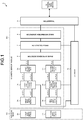
- a rotation angle detection device 1 according to the first embodiment includes a rotating body 100 having a first magnetic track 2A and a second magnetic track 2B, a magnetic sensor module 200, a transmitter 9, and storage 10.
- the magnetic sensor module 200 includes a first magnetic sensor 3A, a first correction calculator 4A, a first phase detector 5A, a second magnetic sensor 3B, a second correction calculator 4B, a second phase detector 5B, a phase difference detector 6, an angle calculator 7, and an angle information generator 8.
- the magnetic sensor module 200 is, for example, integrated into one IC chip. This integration can lead to, for example, a reduction in number of parts constituting the rotation angle detection device 1, an improvement in positional accuracy between the first magnetic sensor 3A and the second magnetic sensor 3B, and reductions in manufacturing cost and assembly cost, and can provide the small and low-cost rotation angle detection device 1.
- the magnetic sensor module 200 may include, for example, the transmitter 9 and the storage 10. This configuration can further reduce the size and cost of the rotation angle detection device 1.
- FIG. 2 is a diagram illustrating an example of the rotating body of the rotation angle detection device according to the first embodiment.
- FIG. 3 is a diagram illustrating an example of the magnetic tracks of the rotating body illustrated in FIG. 2 .
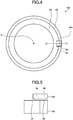
- FIG. 4 is a diagram illustrating an arrangement example of the magnetic sensor module of the rotation angle detection device according to the first embodiment.
- FIG. 5 is a sectional view, along IV-IV illustrated in FIG. 4 , of the rotation angle detection device according to the first embodiment.
- FIG. 6 is a diagram illustrating an example of the magnetic sensors of the rotation angle detection device according to the first embodiment.
- the first magnetic track 2A along which magnetic pole pairs 2A1 are arranged at even intervals and the second magnetic track 2B along which magnetic pole pairs 2B1 are arranged at even intervals are provided on the rotating body 100 of the first embodiment so as to be arranged in the radial direction in concentric ring shapes having the axis center at a rotation axis X of the rotating body 100.
- Each of the magnetic pole pairs has a north pole and a south pole.
- the first magnetic track 2A and the second magnetic track 2B of the first embodiment are obtained by, for example, circumferentially alternately magnetizing one end face in the axial direction of the rotating body 100 into the north pole and the south pole at even intervals.
- the circumferentially different magnetic poles are alternately arranged at equal intervals, for example, such that, in FIG. 3 , shaded portions are the north poles and non-shaded portions are south poles.
- the first magnetic track 2A includes 32 pairs of the magnetic pole pairs 2A1.
- the second magnetic track 2B includes 31 pairs of the magnetic pole pairs 2B1.
- P P is a natural number
- the rotating body 100 can include, for example, neodymium magnets, ferrite magnets, or samarium-cobalt magnets according to a required magnetic flux density.
- the present embodiment has an axial configuration in which the first magnetic track 2A and the second magnetic track 2B are magnetized on one end face in the axial direction of the rotating body 100.
- Such a configuration can thin the rotation angle detection device 1 in the axial direction thereof, and can enlarge a hollow hole thereof.
- This configuration can expand the scope of application of the rotation angle detection device 1 according to the first embodiment, including, for example, applications to inner-ring rotating and outer-ring rotating bearings, and applications to structures of devices in which cables are wired through the hollow hole.
- the configuration can also increase the degree of freedom of designing a device to which the rotation angle detection device 1 according to the first embodiment is applied.
- the magnetic sensor module 200 of the first embodiment is provided so as to be opposed in the axial direction to the rotating body 100 that has the first magnetic track 2A and the second magnetic track 2B, with a gap therebetween.
- the first magnetic sensor 3A of the magnetic sensor module 200 is opposed to the first magnetic track 2A and detects a magnetic field of the first magnetic track 2A.
- the second magnetic sensor 3B of the magnetic sensor module 200 is opposed to the second magnetic track 2B and detects a magnetic field of the second magnetic track 2B.
- the magnetic sensor module 200 is provided at a fixed place that does not rotate in synchronization with the rotating body 100.
- the first magnetic sensor 3A includes two magnetic sensor elements 3A1 and 3A2 arranged separately in the direction of arrangement of the magnetic pole pairs 2A1 so as to have a phase difference therebetween of 90 degrees in terms of electrical angle on the assumption that one period corresponds to a pitch of each of the magnetic pole pairs 2A1 on the first magnetic track 2A.
- the second magnetic sensor 3B includes two magnetic sensor elements 3B1 and 3B2 arranged separately in the direction of arrangement of the magnetic pole pairs 2B1 so as to have a phase difference therebetween of 90 degrees in terms of electrical angle on the assumption that one period corresponds to a pitch of each of the magnetic pole pairs 2B1 on the second magnetic track 2B.
- magnetic sensor elements such as Hall elements or magnetoresistance (MR) effect sensors
- MR magnetoresistance
- the first magnetic sensor 3A outputs a first sine signal sin ⁇ i 1 and a first cosine signal cos ⁇ i 1 corresponding to the phase in the magnetic pole pair 2A1.
- the second magnetic sensor 3B outputs a second sine signal sin ⁇ i 2 and a second cosine signal cos ⁇ i 2 corresponding to the phase in the magnetic pole pair 2B1.
- the first sine signal sin ⁇ i 1 and the first cosine signal cos ⁇ i 1 output from the first magnetic sensor 3A are supplied to the first correction calculator 4A.
- the second sine signal sin ⁇ i 2 and the second cosine signal cos ⁇ i 2 output from the second magnetic sensor 3B are supplied to the second correction calculator 4B.
- the first correction calculator 4A performs correction calculation processing described later on the first sine signal sin ⁇ i 1 and the first cosine signal cos ⁇ i 1 thus supplied, and outputs a first corrected sine signal sin ⁇ o 1 and a first corrected cosine signal cos ⁇ ⁇ 1.
- the second correction calculator 4B performs the correction calculation processing described later on the second sine signal sin ⁇ i 2 and the second cosine signal cos i ⁇ 2 and outputs a second corrected sine signal sin ⁇ ⁇ 2 and a second corrected cosine signal cos ⁇ ⁇ 2.
- the correction calculation processing performed by the first correction calculator 4A and the second correction calculator 4B will be described in detail later.
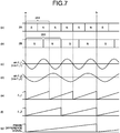
- FIG. 7 is a diagram illustrating waveform examples of respective portions of the rotation angle detection device according to the first embodiment.
- Part (a) of FIG. 7 illustrates a magnetic pole pattern of the first magnetic track 2A
- part (b) of FIG. 7 illustrates an example of a magnetic pole pattern of the second magnetic track 2B.
- Part (c) of FIG. 7 illustrates an input signal waveform of the first phase detector 5A
- part (d) of FIG. 7 illustrates an input signal waveform of the second phase detector 5B.
- Part (e) of FIG. 7 illustrates a detected phase signal waveform output from the first phase detector 5A
- part (f) of FIG. 7 illustrates a detected phase signal waveform output from the second phase detector 5B.
- Part (g) of FIG. 7 illustrates a phase difference signal waveform output from the phase difference detector 6.
- FIG. 7 illustrates an example in which two of the magnetic pole pairs 2B1 on the second magnetic track 2B correspond to a segment from point a to point b consisting of three of the magnetic pole pairs 2A1 on the first magnetic track 2A.
- the phase of a detection signal of the first magnetic sensor 3A coincides with the phase of a detection signal of the second magnetic sensor 3B at point a and point b.
- an absolute angle with respect to point a can be detected in any position up to point b. In this manner, the absolute angle can be detected between the two points at which the phase of the detection signal of the first magnetic sensor 3A coincides with the phase of the detection signal of the second magnetic sensor 3B.
- the magnetic sensor module 200 can detect the absolute angle in the entire circumference of the rotating body 100 with respect to point A serving as the origin position where the phase of the detection signal of the first magnetic sensor 3A coincides with the phase of the detection signal of the second magnetic sensor 3B.
- the relation between the number of the magnetic pole pairs 2A1 on the first magnetic track 2A and the number of the magnetic pole pairs 2B1 on the second magnetic track 2B is not limited to that of the example illustrated in FIG. 3 .
- the configuration may be such that the number of the magnetic pole pairs 2B1 on the second magnetic track 2B is P + 1 when the number of the magnetic pole pairs 2A1 on the first magnetic track 2A is P.
- the phase difference detector 6 outputs the phase difference signal exemplified in part (g) of FIG. 7 based on the respective detected phase signals output from the first phase detector 5A and the second phase detector 5B.
- the angle calculator 7 performs processing to convert the phase difference obtained by the phase difference detector 6 into the absolute angle in accordance with a preset calculation parameter.
- the calculation parameter used by the angle calculator 7 is stored in the storage 10.
- the angle information generator 8 is further provided at the subsequent stage of the angle calculator 7.
- the angle information generator 8 generates, for example, a phase ABZ signal composed of a phase A signal and a phase B signal different from each other in phase by 90 degrees, and a phase Z signal indicating the origin position, as information including the absolute angle calculated by the angle calculator 7 (hereinafter, also called "absolute angle information").
- the phase A signal and the phase B signal only need to be obtained using, for example, either one set of a set of the first corrected sine signal and the first corrected cosine signal, which are the outputs from the first correction calculator 4A, and a set of the second corrected sine signal and the second corrected cosine signal, which are the outputs of the second correction calculator 4B.
- the transmitter 9 converts the absolute angle information generated by the angle information generator 8 into an appropriate signal (for example, a phase ABZ signal, a parallel signal, serial data, an analog voltage, or a pulse-width modulated (PWM) signal) and outputs the result to an external control device.
- an appropriate signal for example, a phase ABZ signal, a parallel signal, serial data, an analog voltage, or a pulse-width modulated (PWM) signal
- the configuration of outputting the absolute angle information converted into the appropriate signal can reduce the number of electrical connection lines to the external control device.
- an aspect may be employed in which, for example, an output request signal for the absolute angle information is transmitted from the external control device to the transmitter 9.
- the rotation angle detection device 1 may be configured to operate in response to the output request signal for the absolute angle information and output the absolute angle information from the transmitter 9.
- the storage 10 stores, in addition to the calculation parameter used by the angle calculator 7, information required for the operation of the rotation angle detection device 1, including, for example, the number (P) of the magnetic pole pairs 2A1 on the first magnetic track 2A, the number (P + 1) of the magnetic pole pairs 2B1 on the second magnetic track 2B, first magnetic sensor correction information used by the first correction calculator 4A, which will be described later, second magnetic sensor correction information used by the second correction calculator 4B, which will be described later, and a reference position of the absolute angle.
- Examples of the storage 10 include a nonvolatile memory.
- the storage 10 stores parameters and arithmetic expressions used by the first correction calculator 4A and the second correction calculator 4B as the first magnetic sensor correction information and the second magnetic sensor correction information.
- the parameters and the arithmetic expressions used by the first correction calculator 4A include information used for correcting the first sine signal sin ⁇ i 1 and the first cosine signal cos ⁇ i 1, which are the detection signals of the first magnetic sensor 3A.
- the parameters and the arithmetic expressions are set as the first magnetic sensor correction information such that the detection signal of the first magnetic sensor 3A comes closer to a pre-assumed reference value of the sine signal or the cosine signal of the first magnetic sensor 3A.
- the parameters and the arithmetic expressions used by the second correction calculator 4B include information used for correcting the second sine signal sin ⁇ i 2 and the second cosine signal cos ⁇ i 2, which are the detection signals of the second magnetic sensor 3B.
- the parameters and the arithmetic expressions are set as the second magnetic sensor correction information such that the detection signal of the second magnetic sensor 3B comes closer to a pre-assumed reference value of the sine signal or the cosine signal of the second magnetic sensor 3B.
- the various parameters and information stored in the storage 10 may be configured to be updatable, for example, from the external control device through the transmitter 9. This configuration allows setting of the rotation angle detection device 1 according to the use situation thereof.
- the first magnetic track 2A and the second magnetic track 2B are the same in configuration and operation, the first magnetic sensor 3A and the second magnetic sensor 3B are the same in configuration and operation, and the first correction calculator 4A and the second correction calculator 4B are the same in configuration and operation. Therefore, in the following description, each of the first magnetic track 2A and the second magnetic track 2B is also called a "magnetic track 2"; each of the first magnetic sensor 3A and the second magnetic sensor 3B is also called a "magnetic sensor 3"; each of the first correction calculator 4A and the second correction calculator 4B is also called a "correction calculator 4"; and each of the first magnetic sensor correction information and the second magnetic sensor correction information is also called “magnetic sensor correction information”.
- FIG. 8 is a diagram illustrating an example of functional blocks of the correction calculator according to the first embodiment.
- the correction calculator 4 includes a normalization processor 41 and a sensor phase corrector 42.
- the correction calculator 4 receives the sine signal sin ⁇ i and the cosine signal cos ⁇ i output from the magnetic sensor 3.
- the correction calculator 4 acquires the magnetic sensor correction information to be applied to the normalization processor 41 and the sensor phase corrector 42 from the storage 10.
- the normalization processor 41 normalizes the sine signal sin ⁇ i and the cosine signal cos ⁇ i output from the magnetic sensor 3 and outputs a normalized sine signal sin ⁇ ' and a normalized cosine signal cos ⁇ ' to the sensor phase corrector 42.
- the sensor phase corrector 42 corrects the phases of the normalized sine signal sin ⁇ ' and the normalized cosine signal cos ⁇ ' and outputs a corrected sine signal sin ⁇ o and a corrected cosine signal cos ⁇ ⁇ .
- FIG. 9 is a diagram illustrating an example of a control block of the normalization processor according to the first embodiment.
- FIG. 10 is a diagram illustrating an example of a normalization operation performed by the normalization processor illustrated in FIG. 9 .
- the normalization processor 41 includes an offset voltage corrector 411.
- a dashed line indicates the sine signal sin ⁇ i (cosine signal cos ⁇ i ), and a solid line indicates the normalized sine signal sin ⁇ ' (normalized cosine signal cos ⁇ ').
- FIGS. 9 and 10 assumes a case where an offset voltage is superimposed on the detection signal of the magnetic sensor 3.
- an average value Vsinave (Vcosave) of the sine signal (cosine signal), which is the detection signal of the magnetic sensor 3, is set as the magnetic sensor correction information and stored in the storage 10 in advance.
- the average value Vsinave may be, for example, an average value of a predetermined number of cycles of the sine signal, or an average value of any one cycle of the sine signal in terms of electrical angle on the magnetic track 2.
- the average value Vcosave may be, for example, an average value of a predetermined number of cycles of the cosine signal, or an average value of any one cycle of the cosine signal in terms of electrical angle on the magnetic track 2.
- the average value Vsinave (Vcosave) of the sine signal (cosine signal) may be, for example, a value measured at a shipping inspection of the rotation angle detection device 1.
- the offset voltage corrector 411 uses the average value Vsinave, which is the detection signal of the magnetic sensor 3, to normalize the offset voltage of the sine signal sin ⁇ i .
- Vsinave the detection signal of the magnetic sensor 3
- the normalized sine signal sin ⁇ ' is calculated by subtracting Vsinave from the sine signal sin ⁇ i , that is, using Expression (1) below.
- Expression (1) above is stored in the storage 10 and set as the magnetic sensor correction information in advance.
- the offset voltage corrector 411 uses Expression (1) above to normalize the offset voltage of the sine signal sin ⁇ i , and thereby outputs the normalized sine signal sin ⁇ ' indicated by the solid line in FIG. 10 .
- the offset voltage corrector 411 uses the average value Vcosave of the cosine signal, which is the detection signal of the magnetic sensor 3, to normalize the offset voltage of the cosine signal cos ⁇ i .
- the normalized cosine signal cos ⁇ ' is calculated by subtracting Vcosave from the cosine signal cos ⁇ i , that is, using Expression (2) below.
- Expression (2) above is stored in the storage 10 and set as the magnetic sensor correction information in advance.
- the offset voltage corrector 411 uses Expression (2) above to normalize the offset voltage of the cosine signal cos ⁇ i , and thereby outputs the normalized cosine signal cos ⁇ ' indicated by the solid line in FIG. 10 .
- FIG. 11 is a diagram illustrating an example, different from that of FIG. 9 , of the control block of the normalization processor according to the first embodiment.
- FIG. 12 is a diagram illustrating an example of the normalization operation performed by the normalization processor illustrated in FIG. 11 .
- the normalization processor 41 includes an amplitude corrector 412.
- a dashed line indicates the sine signal sin ⁇ i (cosine signal cos ⁇ i )
- a solid line indicates the normalized sine signal sin ⁇ ' (normalized cosine signal cos ⁇ ').
- FIGS. 11 and 12 assumes a case where a variation in output amplitude is present in the detection signal of the magnetic sensor 3.
- a maximum value Vsinmax (Vcosmax) and a minimum value Vsinmin (Vcosmin) of the sine signal (cosine signal), which is the detection signal of the magnetic sensor 3, are set as the magnetic sensor correction information and stored in the storage 10 in advance.
- the maximum value Vsinmax of the sine signal may be, for example, the average value of maximum values of the sine signal in respective cycles of a predetermined number of cycles, or a maximum value of the sine signal in any one cycle, in terms of electrical angle on the magnetic track 2.
- the minimum value Vsinmin of the sine signal may be, for example, the average value of minimum values of the sine signal in respective cycles of a predetermined number of cycles, or a minimum value of the sine signal in any one cycle, in terms of electrical angle on the magnetic track 2.
- the maximum value Vcosmax of the cosine signal may be, for example, the average value of maximum values of the cosine signal in respective cycles of a predetermined number of cycles, or a maximum value of the cosine signal in any one cycle, in terms of electrical angle on the magnetic track 2.
- the minimum value Vcosmin of the cosine signal may be, for example, the average value of minimum values of the cosine signal in respective cycles of a predetermined number of cycles, or a minimum value of the cosine signal in any one cycle, in terms of electrical angle on the magnetic track 2.
- the maximum value Vsinmax (Vcosmax) and the minimum value Vsinmin (Vcosmin) of the sine signal (cosine signal) may be, for example, values measured at the shipping inspection of the rotation angle detection device 1.
- the amplitude corrector 412 uses the maximum value Vsinmax and the minimum value Vsinmin of the sine signal to normalize the amplitude of the sine signal sin ⁇ i .
- the normalized sine signal sin ⁇ ' is calculated by dividing the sine signal sin ⁇ i by a value obtained by dividing the absolute value of a value obtained by subtracting Vsinmin from Vsinmax by two, that is, using Expression (3) below.
- sin ⁇ ⁇ ′ sin ⁇ i / V sin max ⁇ V sin min / 2
- Expression (3) above is stored in the storage 10 and set as the magnetic sensor correction information in advance.
- the amplitude corrector 412 uses Expression (3) above to normalize the amplitude of the sine signal sin ⁇ i , and thereby outputs the normalized sine signal sin ⁇ ' having the normalized amplitude indicated by the solid line in FIG. 12 .
- the amplitude corrector 412 uses the maximum value Vcosmax and the minimum value Vcosmin of the cosine signal to normalize the amplitude of the cosine signal cos ⁇ i .
- the normalized cosine signal cos ⁇ ' is calculated by dividing the cosine signal cos ⁇ i by a value obtained by dividing the absolute value of a value obtained by subtracting Vcosmin from Vcosmax by two, that is, using Expression (4) below.
- cos ⁇ ⁇ ′ cos ⁇ i / V cos max ⁇ V cos min / 2
- Expression (4) above is stored in the storage 10 and set as the magnetic sensor correction information in advance.
- the amplitude corrector 412 uses Expression (4) above to normalize the amplitude of the cosine signal cos ⁇ i , and thereby outputs the normalized cosine signal cos ⁇ ' having the normalized amplitude indicated by the solid line in FIG. 12 .
- FIG. 13 is a diagram illustrating an example of the control block in which the normalization processor according to the first embodiment includes both the offset voltage corrector and the amplitude corrector.
- the offset voltage corrector 411 uses the average value Vsinave, which is the detection signal of the magnetic sensor 3, to normalize the offset voltage of the sine signal sin ⁇ i .
- Vsinave the detection signal of the magnetic sensor 3
- a normalized sine signal sin ⁇ " is calculated by subtracting Vsinave from the sine signal sin ⁇ i , that is, using Expression (5) below.
- Expression (5) above is stored in the storage 10 and set as the magnetic sensor correction information in advance.
- the offset voltage corrector 411 uses Expression (5) above to normalize the offset voltage of the sine signal sin ⁇ i .
- the offset voltage corrector 411 uses the average value Vcosave of the cosine signal, which is the detection signal of the magnetic sensor 3, to normalize the offset voltage of the cosine signal cos ⁇ i .
- a normalized cosine signal cos ⁇ " is calculated by subtracting Vcosave from the cosine signal cos ⁇ i , that is, using Expression (6) below.
- Expression (6) above is stored in the storage 10 and set as the magnetic sensor correction information in advance.
- the offset voltage corrector 411 uses Expression (6) above to normalize the offset voltage of the cosine signal cos ⁇ i .
- the amplitude corrector 412 uses the maximum value Vsinmax and the minimum value Vsinmin of the sine signal to normalize the amplitude of the normalized sine signal sin ⁇ ".
- the normalized sine signal sin ⁇ ' is calculated by dividing the normalized sine signal sin ⁇ " by the value obtained by dividing the absolute value of the value obtained by subtracting Vsinmin from Vsinmax by two, that is, using Expression (7) below.
- sin ⁇ ⁇ ′ sin ⁇ ⁇ " / V sin max ⁇ V sin min / 2
- Expression (7) above is stored in the storage 10 and set as the magnetic sensor correction information in advance.
- the amplitude corrector 412 uses Expression (7) above to normalize the amplitude of the normalized sine signal sin ⁇ ".
- the amplitude corrector 412 uses the maximum value Vcosmax and the minimum value Vcosmin of the cosine signal to normalize the amplitude of the normalized cosine signal cos ⁇ ".
- the normalized cosine signal cos ⁇ ' is calculated by dividing the normalized cosine signal cos ⁇ " by the value obtained by dividing the absolute value of the value obtained by subtracting Vcosmin from Vcosmax by two, that is, using Expression (8) below.
- cos ⁇ ⁇ ′ cos ⁇ ⁇ " / V cos max ⁇ V cos min / 2
- Expression (8) above is stored in the storage 10 and set as the magnetic sensor correction information in advance.
- the amplitude corrector 412 uses Expression (8) above to normalize the amplitude of the normalized cosine signal cos ⁇ ".
- the offset voltage corrector 411 first calculates the normalized sine signal sin ⁇ " and the normalized cosine signal cos ⁇ ", respectively, by normalizing the offset voltages of the sine signal sin ⁇ i and the cosine signal cos ⁇ i , and then the amplitude corrector 412 calculates the normalized sine signal sin ⁇ ' and the normalized cosine signal cos ⁇ ', respectively, by normalizing the amplitude values of the normalized sine signal sin ⁇ " and the normalized cosine signal cos ⁇ ".
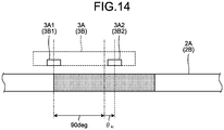
- FIG. 14 is a diagram illustrating an example of a correction target of the sensor phase corrector according to the first embodiment.
- the magnetic sensor elements 3A1 and 3A2 of the first magnetic sensor 3A are arranged separately from each other in the direction of arrangement of the magnetic pole pairs 2A1 so as to have a phase difference therebetween of 90 degrees in terms of electrical angle on the assumption that one period corresponds to a pitch of each of the magnetic pole pairs 2A1 on the first magnetic track 2A
- the magnetic sensor elements 3B1 and 3B2 of the second magnetic sensor 3B are arranged separately from each other in the direction of arrangement of the magnetic pole pairs 2B1 so as to have a phase difference therebetween of 90 degrees in terms of electrical angle on the assumption that one period corresponds to a pitch of each of the magnetic pole pairs 2B1 on the second magnetic track 2B.
- the present embodiment assumes a case where an error (hereinafter, called a "sensor phase error”) ⁇ ic is included between an output phase of the magnetic sensor element 3A1 (3B1) and an output phase of the magnetic sensor element 3A2 (3B2).
- a sensor phase error an error
- ⁇ ic an error (hereinafter, called a "sensor phase error") ⁇ ic is included between an output phase of the magnetic sensor element 3A1 (3B1) and an output phase of the magnetic sensor element 3A2 (3B2).
- ⁇ ic an error (hereinafter, called a "sensor phase error”) ⁇ ic is included between an output phase of the magnetic sensor element 3A1 (3B1) and an output phase of the magnetic sensor element 3A2 (3B2).
- Such an assumption can be applied to cases including, for example, a case where a variation is present in the intervals between the magnetic poles provided on the magnetic track 2 and a case where the radial position of the magnetic sensor 3 on the magnetic track 2 varies during one turn of the rotating body 100, such
- FIG. 14 and FIGS. 15 and 16 represent an example of correcting the output phase of the magnetic sensor element 3A2 (3B2) using the magnetic sensor element 3A1 (3B1) as a reference.
- FIG. 15 is a diagram illustrating an example of a control block of the sensor phase corrector according to the first embodiment.
- FIG. 16 is a diagram illustrating an example of a phase correction operation performed by the sensor phase corrector illustrated in FIG. 15 .
- a dashed line indicates the normalized cosine signal cos ⁇ '
- a solid line indicates the corrected cosine signal cos ⁇ ⁇ .
- the sensor phase error ⁇ ic between the output phase of the magnetic sensor element 3A1 (3B1) and the output phase of the magnetic sensor element 3A2 (3B2) is set as the first magnetic sensor correction information (second magnetic sensor correction information), and stored in the storage 10 in advance.
- the sensor phase error ⁇ ic may be, for example, a value measured at the shipping inspection of the rotation angle detection device 1.
- the sensor phase corrector 42 uses the sensor phase error ⁇ ic to correct the phase of the normalized cosine signal cos ⁇ ' using the normalized sine signal sin ⁇ ' as a reference.
- the sensor phase corrector 42 does not correct the normalized sine signal sin ⁇ ' serving as the reference.
- the corrected sine signal sin ⁇ o in the sensor phase corrector 42 can be represented by Expression (9) below.
- the sensor phase corrector 42 uses Expression (10) above to calculate the corrected cosine signal cos ⁇ ⁇ .
- Expression (10) above is also called a "first phase correction arithmetic expression”.
- Expression (10) above that is, the first phase correction arithmetic expression is stored in the storage 10 and set as the first magnetic sensor correction information (second magnetic sensor correction information) in advance.
- the sensor phase corrector 42 uses Expression (10) above, that is, the first phase correction arithmetic expression to correct the phase of the normalized cosine signal cos ⁇ ', and thereby outputs the corrected cosine signal cos ⁇ o indicated by the solid line in FIG. 16 .
- FIG. 17 is a diagram illustrating an example, different from that of FIG. 14 , of the correction target of the sensor phase corrector according to the first embodiment.
- FIG. 17 and FIGS. 18 and 19 represent an example of correcting the output phase of the magnetic sensor element 3A1 (3B1) using the magnetic sensor element 3A2 (3B2) as a reference.
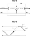
- FIG. 18 is a diagram illustrating an example, different from that of FIG. 15 , of the control block of the sensor phase corrector according to the first embodiment.
- FIG. 19 is a diagram illustrating an example of a phase correction operation performed by the sensor phase corrector illustrated in FIG. 18 .
- a dashed line indicates the normalized sine signal sin ⁇ '
- a solid line indicates the corrected sine signal sin ⁇ ⁇ .
- the sensor phase error ⁇ ic between the output phase of the magnetic sensor element 3A1 (3B1) and the output phase of the magnetic sensor element 3A2 (3B2) is set as the first magnetic sensor correction information (second magnetic sensor correction information), and stored in the storage 10 in advance.
- the sensor phase error ⁇ ic may be, for example, a value measured at the shipping inspection of the rotation angle detection device 1.
- the sensor phase corrector 42a uses the sensor phase error ⁇ ic to correct the phase of the normalized sine signal sin ⁇ ' using the normalized cosine signal cos ⁇ ' as a reference.
- the sensor phase corrector 42a does not correct the normalized cosine signal cos ⁇ ' serving as the reference.
- the corrected cosine signal cos ⁇ o in the sensor phase corrector 42a can be represented by Expression (11) below.
- the sensor phase corrector 42 uses Expression (12) above to calculate the corrected sine signal sin ⁇ ⁇ .
- Expression (12) above is also called a "second phase correction arithmetic expression”.
- Expression (12) above that is, the second phase correction arithmetic expression is stored in the storage 10 and set as the first magnetic sensor correction information (second magnetic sensor correction information) in advance.
- the sensor phase corrector 42a uses Expression (12) above, that is, the second phase correction arithmetic expression to correct the phase of the normalized sine signal sin ⁇ ', and thereby outputs the corrected sine signal sin ⁇ o indicated by the solid line in FIG. 19 .
- the first correction calculator 4A includes the sensor phase corrector 42 or the sensor phase corrector 42a and thus can correct the output phase of the first magnetic sensor 3A.
- the second correction calculator 4B includes the sensor phase corrector 42 or the sensor phase corrector 42a and thus can correct the output phase of the second magnetic sensor 3B.
- FIG. 20 is a diagram illustrating an example of the specific procedure of the rotation angle detection method according to the first embodiment.
- the first correction calculator 4A corrects the first sine signal sin ⁇ i 1 and the first cosine signal cos ⁇ i 1 to the first corrected sine signal sin ⁇ o 1 and the first corrected cosine signal cos ⁇ ⁇ 1, respectively, based on the first magnetic sensor correction information; and the second correction calculator 4B corrects the second sine signal sin ⁇ i 2 and the second cosine signal cos ⁇ i 2 to the second corrected sine signal sin ⁇ ⁇ 2 and the second corrected cosine signal cos ⁇ ⁇ 2, respectively, based on the second magnetic sensor correction information (Step S101).
- the first phase detector 5A calculates a phase of the first corrected sine signal sin ⁇ o 1 and the first corrected cosine signal cos ⁇ ⁇ 1
- the second phase detector 5B calculates a phase of the second corrected sine signal sin ⁇ ⁇ 2 and the second corrected cosine signal cos ⁇ ⁇ 2 (Step S102).
- the phase difference detector 6 calculates the phase difference between the first magnetic sensor 3A and the second magnetic sensor 3B based on the detected phase of the first magnetic sensor 3A and the detected phase of the second magnetic sensor 3B (Step S103).
- the angle calculator 7 converts the phase difference output from the phase difference detector 6 into the absolute angle (Step S104).
- the rotation angle detection device 1 includes the rotating body 100, the first magnetic sensor 3A, the second magnetic sensor 3B, the storage 10, the first correction calculator 4A, the second correction calculator 4B, the first phase detector 5A, the second phase detector 5B, the phase difference detector 6, and the angle calculator 7.
- the rotating body 100 is a body on which the first magnetic track 2A along which the magnetic pole pairs 2A1 are arranged at even intervals and the second magnetic track 2B along which the magnetic pole pairs 2B1 are arranged at even intervals, are provided so as to be arranged in the radial direction in concentric ring shapes having the axis center at the rotation axis X.
- Each of the magnetic pole pairs has the north pole and the south pole.
- the number of the magnetic pole pairs 2A1 on the first magnetic track 2A is P (P is a natural number)
- the number of the magnetic pole pairs 2B1 on the second magnetic track 2B is P - 1 or P + 1.
- the first magnetic sensor 3A detects the magnetic field of the first magnetic track 2A and outputs the first sine signal sin ⁇ i 1 and the first cosine signal cos ⁇ i 1.
- the second magnetic sensor 3B detects the magnetic field of the second magnetic track 2B and outputs the second sine signal sin ⁇ i 2 and the second cosine signal cos ⁇ i 2.
- the storage 10 stores the first magnetic sensor correction information and the second magnetic sensor correction information that are preset.
- the first magnetic sensor correction information is preset such that the value of the first sine signal sin ⁇ i 1 output by the first magnetic sensor 3A corresponding to the rotation angle of the first magnetic track 2A comes closer to the reference value of the sine signal of the first magnetic sensor 3A, or such that the value of the first cosine signal cos ⁇ i 1 output by the first magnetic sensor 3A corresponding to the rotation angle of the first magnetic track 2A comes closer to the reference value of the cosine signal of the first magnetic sensor 3A.
- the second magnetic sensor correction information is preset such that the value of the second sine signal sin ⁇ i 2 output by the second magnetic sensor 3B corresponding to the rotation angle of the second magnetic track 2B comes closer to the reference value of the sine signal of the second magnetic sensor 3B, or such that the value of the second cosine signal cos ⁇ i 2 output by the second magnetic sensor 3B corresponding to the rotation angle of the second magnetic track 2B comes closer to the reference value of the cosine signal of the second magnetic sensor 3B.
- the first correction calculator 4A corrects the first sine signal sin ⁇ i 1 and the first cosine signal cos ⁇ i 1 to the first corrected sine signal sin ⁇ o 1 and the first corrected cosine signal cos ⁇ o 1 based on the first magnetic sensor correction information.
- the second correction calculator 4B corrects the second sine signal sin ⁇ i 2 and the second cosine signal cos ⁇ i 2 to the second corrected sine signal sin ⁇ ⁇ 2 and the second corrected cosine signal cos ⁇ ⁇ 2 based on the second magnetic sensor correction information.
- the first phase detector 5A calculates the phase of the first corrected sine signal sin ⁇ o 1 and the first corrected cosine signal cos ⁇ ⁇ 1.
- the second phase detector 5B calculates the phase of the second corrected sine signal sin ⁇ ⁇ 2 and the second corrected cosine signal cos ⁇ ⁇ 2.
- the phase difference detector 6 calculates the phase difference between the first magnetic sensor 3A and the second magnetic sensor 3B based on the detected phase of the first magnetic sensor 3A and the detected phase of the second magnetic sensor 3B.
- the angle calculator 7 converts the phase difference into the absolute angle.
- the rotation angle detection device 1 can correct in real time the sine signals and the cosine signals before the phases are calculated by the first phase detector 5A and the second phase detector 5B.
- the phases are calculated using the corrected sine signals and the corrected cosine signals that have been corrected from the sine signals and the cosine signals based on the known preset magnetic sensor correction information. Therefore, the detection accuracy of the absolute angle of the rotating body 100 is improved. Accordingly, the rotation angle detection device 1 according to the present embodiment can accurately detect the absolute angle of the rotating body 100.
- the average values Vsinave and Vcosave of the sine signal and the cosine signal that are the detection signals of the first magnetic sensor 3A (second magnetic sensor 3B), are stored in advance as the first magnetic sensor correction information (second magnetic sensor correction information) in the storage 10; and the offset voltage corrector 411 uses the average value Vsinave of the sine signal to correct the sine signal and uses the average value Vcosave of the cosine signal to correct the cosine signal.
- the offset voltages of the sine signal and the cosine signal can be normalized.
- the maximum values Vsinmax and Vcosmax and the minimum values Vsinmin and Vcosmin of the sine signal and the cosine signal that are the detection signals of the first magnetic sensor 3A (second magnetic sensor 3B), are stored in advance as the first magnetic sensor correction information (second magnetic sensor correction information) in the storage 10; and the amplitude corrector 412 uses the maximum value Vsinmax and the minimum value Vsinmin of the sine signal to correct the sine signal and uses the maximum value Vcosmax and the minimum value Vcosmin of the cosine signal to correct the cosine signal.
- the amplitude values of the sine signal and the cosine signal can be normalized.
- each of the correction calculators 4 (the first correction calculator 4A and the second correction calculator 4B) includes both the offset voltage corrector 411 and the amplitude corrector 412
- the correction calculators 4 can normalize both the offset voltages and the amplitude values of the sine signal and the cosine signal.
- the sensor phase error ⁇ ic between the output phase of the magnetic sensor element 3A1 (3B1) and the output phase of the magnetic sensor element 3A2 (3B2) in the first magnetic sensor 3A (second magnetic sensor 3B) and the first phase correction arithmetic expression are stored in advance as the first magnetic sensor correction information (second magnetic sensor correction information) in the storage 10, and the sensor phase corrector 42 uses the sensor phase error ⁇ ic and the first phase correction arithmetic expression to correct the cosine signal.
- the output phase of the magnetic sensor element 3A2 (3B2) can be corrected using the magnetic sensor element 3A1 (3B1) as the reference.
- the sensor phase error ⁇ ic between the output phase of the magnetic sensor element 3A1 (3B1) and the output phase of the magnetic sensor element 3A2 (3B2) in the first magnetic sensor 3A (second magnetic sensor 3B) and the second phase correction arithmetic expression are stored in advance as the first magnetic sensor correction information (second magnetic sensor correction information) in the storage 10, and the sensor phase corrector 42a uses the sensor phase error ⁇ ic and the second phase correction arithmetic expression to correct the sine signal.
- the output phase of the magnetic sensor element 3A1 (3B1) can be corrected using the magnetic sensor element 3A2 (3B2) as the reference.
- This configuration can improve the accuracy of position detection by the rotation angle detection device, and as a result, can contribute to an improvement in rotation control performance of various devices.
- the rotation angle detection method includes; correcting the first sine signal sin ⁇ i 1 and the first cosine signal cos ⁇ i 1 to the first corrected sine signal sin ⁇ o 1 and the first corrected cosine signal cos ⁇ o 1 based on the first magnetic sensor correction information that is preset such that the value of the first sine signal sin ⁇ i 1 output by the first magnetic sensor 3A, which detects the magnetic field of the first magnetic track 2A and outputs the first sine signal sin ⁇ i 1 and the first cosine signal cos ⁇ i 1 corresponding to the rotation angle of the first magnetic track 2A along which the magnetic pole pairs 2A1 each having the north pole and the south pole are arranged at even intervals, comes closer to the reference value of the sine signal of the first magnetic sensor 3A, or such that the value of the first cosine signal cos ⁇ i 1 output by the first magnetic sensor 3A corresponding to the rotation angle of the first magnetic track 2A comes closer to the reference value of the cosine signal of the first magnetic
- the sine signals and the cosine signals can be corrected in real time before the phases are calculated by the first phase detector 5A and the second phase detector 5B.
- the phases are calculated using the corrected sine signals and the corrected cosine signals that have been corrected from the sine signals and the cosine signals based on the known preset magnetic sensor correction information. Therefore, the detection accuracy of the absolute angle of the rotating body 100 is improved. Accordingly, with the rotation angle detection method according to the present embodiment, the absolute angle of the rotating body 100 can be accurately detected.
- the first embodiment described above exemplifies the axial configuration in which the first magnetic track 2A and the second magnetic track 2B are magnetized on one end face in the axial direction of the rotating body 100.
- the configuration is, however, not limited thereto, and may be, for example, a radial configuration in which the first magnetic track 2A and the second magnetic track 2B are magnetized on the outer circumferential surface of the rotating body 100 and provided so as to be arranged in the axial direction.
- a configuration, a rotating body, magnetic tracks, and an arrangement of a magnetic sensor module of a rotation angle detection device according to a second embodiment are the same as those of the first embodiment, and therefore description thereof will not be repeated.
- the same components as those described above in the first embodiment are denoted by the same reference signs, and the description thereof will not be repeated.
- each of the first magnetic track 2A and the second magnetic track 2B is also called a “magnetic track 2"; each of the first magnetic sensor 3A and the second magnetic sensor 3B is also called a “magnetic sensor 3"; each of the first correction calculator 4A and the second correction calculator 4B is also called a “correction calculator 4a”; and each of the first magnetic sensor correction information and the second magnetic sensor correction information is also called “magnetic sensor correction information”.
- FIG. 21 is a diagram illustrating an example of functional blocks of the correction calculator according to the second embodiment.
- the correction calculator 4a according to the second embodiment includes the normalization processor 41 described in the first embodiment and an amplitude variation reducer 43.
- the correction calculator 4a receives the sine signal sin ⁇ i and the cosine signal cos ⁇ i output from the magnetic sensor 3.
- the correction calculator 4a acquires the magnetic sensor correction information to be applied to the normalization processor 41 and the amplitude variation reducer 43 from the storage 10.
- the normalization processor 41 normalizes the sine signal sin ⁇ i and the cosine signal cos ⁇ i output from the magnetic sensor 3 and outputs the normalized sine signal sin ⁇ ' and the normalized cosine signal cos ⁇ ' to the sensor phase corrector 42.
- the amplitude variation reducer 43 corrects amplitude variations of the normalized sine signal sin ⁇ ' and the normalized cosine signal cos ⁇ ' and outputs the corrected sine signal sin ⁇ o and the corrected cosine signal cos ⁇ ⁇ .
- FIG. 22 is a diagram illustrating an example of a control block of the amplitude variation reducer according to the second embodiment.
- the control block of the normalization processor 41 is the same as that of the first embodiment, and therefore description thereof will not be repeated.
- the present embodiment assumes a case where the output amplitude of the magnetic sensor 3 varies. Such an assumption can be applied to cases including, for example, a case where an axial surface provided with the magnetic track 2 of the rotating body 100 is not smooth and a case where the axial distance between the magnetic sensor 3 and the magnetic track 2 varies during one turn of the rotating body 100, such as a case where the rotation axis X of the rotating body 100 is tilted.
- the amplitude variation reducer 43 illustrated in FIG. 22 uses Expression (13) below to calculate the corrected sine signal sin ⁇ ⁇ .
- Expression (13) below is also called a "first amplitude variation correction arithmetic expression”.
- Expression (13) above that is, the first amplitude variation correction arithmetic expression is stored in the storage 10 and set as the magnetic sensor correction information in advance.
- the amplitude variation reducer 43 uses Expression (13) above, that is, the first amplitude variation correction arithmetic expression to calculate the corrected sine signal sin ⁇ o by reducing the cyclic amplitude variation of the normalized sine signal sin ⁇ ' and outputs the result.
- the amplitude variation reducer 43 illustrated in FIG. 22 uses Expression (14) below to calculate the corrected cosine signal cos ⁇ ⁇ .
- Expression (14) below is also called a "second amplitude variation correction arithmetic expression”.
- Expression (14) above that is, the second amplitude variation correction arithmetic expression is stored in the storage 10 and set as the magnetic sensor correction information in advance.
- the amplitude variation reducer 43 uses Expression (14) above, that is, the second amplitude variation correction arithmetic expression to calculate the corrected cosine signal cos ⁇ o by reducing the cyclic amplitude variation of the normalized cosine signal cos ⁇ ' and outputs the result.
- the first correction calculator 4A includes the amplitude variation reducer 43 and thus can correct the variation in the output amplitude of the first magnetic sensor 3A.
- the second correction calculator 4B includes the amplitude variation reducer 43 and thus can correct the variation in the output amplitude of the second magnetic sensor 3B.
- the first amplitude variation correction arithmetic expression and the second amplitude variation correction arithmetic expression are stored in advance as the first sensor correction information in the storage 10, and the amplitude variation reducer 43 uses the first amplitude variation correction arithmetic expression and the second amplitude variation correction arithmetic expression to correct the sine signal and the cosine signal.
- the variation in the output amplitude of the first magnetic sensor 3A (second magnetic sensor 3B) can be corrected.
- the above-described configuration can improve the accuracy of position detection by the rotation angle detection device, and as a result, can contribute to an improvement in rotation control performance of various devices.
- a configuration, a rotating body, magnetic tracks, and an arrangement of a magnetic sensor module of a rotation angle detection device according to a third embodiment are the same as those of the first and second embodiments, and therefore description thereof will not be repeated.
- the same components as those described above in the first and second embodiments are denoted by the same reference signs, and the description thereof will not be repeated.
- each of the first magnetic track 2A and the second magnetic track 2B is also called a “magnetic track 2"; each of the first magnetic sensor 3A and the second magnetic sensor 3B is also called a “magnetic sensor 3"; each of the first correction calculator 4A and the second correction calculator 4B is also called a “correction calculator 4b"; and each of the first magnetic sensor correction information and the second magnetic sensor correction information is also called “magnetic sensor correction information”.
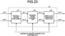
- FIG. 23 is a diagram illustrating an example of functional blocks of the correction calculator according to the third embodiment.
- FIG. 24 is a diagram illustrating an example of the control block in which the correction calculator according to the first embodiment includes both the sensor phase corrector and the amplitude variation reducer.
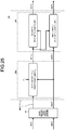
- FIG. 25 is a diagram illustrating an example, different from that of FIG. 24 , of the control block in which the correction calculator according to the first embodiment includes both the sensor phase corrector and the amplitude variation reducer.
- the correction calculator 4b includes the normalization processor 41 and the sensor phase corrector 42 (or the sensor phase corrector 42a) described in the first embodiment and the amplitude variation reducer 43 described in the second embodiment.
- the correction calculator 4b receives the sine signal sin ⁇ i and the cosine signal cos ⁇ i output from the magnetic sensor 3.
- the correction calculator 4b acquires the magnetic sensor correction information to be applied to the normalization processor 41 and the amplitude variation reducer 43 from the storage 10.
- the normalization processor 41 normalizes the sine signal sin ⁇ i and the cosine signal cos ⁇ i output from the magnetic sensor 3 and outputs the normalized sine signal sin ⁇ ' and the normalized cosine signal cos ⁇ ' to the sensor phase corrector 42 or 42a.
- the sensor phase corrector 42 or 42a corrects the phase of the normalized sine signal sin ⁇ ' or the normalized cosine signal cos ⁇ ' and outputs a corrected sine signal sin ⁇ ⁇ ' and a corrected cosine signal cos ⁇ ⁇ '.
- the sensor phase corrector 42 illustrated in FIG. 24 does not correct the normalized sine signal sin ⁇ ' serving as the reference.
- the corrected sine signal sin ⁇ ⁇ ' in the sensor phase corrector 42 can be represented by Expression (15) below.
- the sensor phase corrector 42 illustrated in FIG. 24 uses Expression (16) below to calculate the corrected cosine signal cos ⁇ ⁇ '.
- Expression (16) below is also called a "first phase correction arithmetic expression" in the same manner as Expression (10) above.
- cos ⁇ o ′ cos ⁇ ′ + ⁇ ic + sin ⁇ ′ ⁇ sin ⁇ ic / cos ⁇ ic
- Expression (16) above that is, the first phase correction arithmetic expression is stored in the storage 10 and set as the magnetic sensor correction information in advance.
- the sensor phase corrector 42 uses Expression (16) above, that is, the first phase correction arithmetic expression to calculate the corrected cosine signal cos ⁇ ⁇ ' by correcting the phase of the normalized cosine signal cos ⁇ ' and outputs the result.
- the amplitude variation reducer 43 corrects the amplitude variations of the corrected sine signal sin ⁇ ⁇ ' and the corrected cosine signal cos ⁇ ⁇ ' and outputs the corrected sine signal sin ⁇ o and the corrected cosine signal cos ⁇ ⁇ .
- the amplitude variation reducer 43 illustrated in FIG. 24 uses Expression (17) below to calculate the corrected sine signal sin ⁇ ⁇ .
- Expression (17) below is also called a "first amplitude variation correction arithmetic expression” in the same manner as Expression (13) above.
- sin ⁇ o sin ⁇ o ′ / 1 ⁇ 1 ⁇ sin 2 ⁇ o ′ + cos 2 ⁇ o ′ / 2
- Expression (17) above that is, the first amplitude variation correction arithmetic expression is stored in the storage 10 and set as the magnetic sensor correction information in advance.
- the amplitude variation reducer 43 uses Expression (17) above, that is, the first amplitude variation correction arithmetic expression to calculate the corrected sine signal sin ⁇ o by reducing the cyclic amplitude variation of the corrected sine signal sin ⁇ ⁇ ' and outputs the result.
- the amplitude variation reducer 43 illustrated in FIG. 24 uses Expression (18) below to calculate the corrected cosine signal cos ⁇ ⁇ .
- Expression (18) below is also called a "second amplitude variation correction arithmetic expression" in the same manner as Expression (14) above.
- cos ⁇ o cos ⁇ o ′ / 1 ⁇ 1 ⁇ sin 2 ⁇ o ′ + cos 2 ⁇ o ′ / 2
- Expression (18) above that is, the second amplitude variation correction arithmetic expression is stored in the storage 10 and set as the magnetic sensor correction information in advance.
- the amplitude variation reducer 43 uses Expression (18) above, that is, the second amplitude variation correction arithmetic expression to calculate the corrected cosine signal cos ⁇ o by reducing the cyclic amplitude variation of the corrected cosine signal cos ⁇ ⁇ ' and outputs the result.
- the sensor phase corrector 42a illustrated in FIG. 25 uses Expression (19) below to calculate the corrected sine signal sin ⁇ ⁇ '.
- Expression (19) below is also called a "second phase correction arithmetic expression" in the same manner as Expression (12) above.
- sin ⁇ o ′ sin ⁇ ′ + ⁇ ic + cos ⁇ ′ ⁇ cos ⁇ ic / sin ⁇ ic
- Expression (19) above that is, the second phase correction arithmetic expression is stored in the storage 10 and set as the magnetic sensor correction information in advance.
- the sensor phase corrector 42a uses Expression (19) above, that is, the second phase correction arithmetic expression to calculate the corrected sine signal sin ⁇ ⁇ ' by correcting the phase of the normalized sine signal sin ⁇ ' and outputs the result.
- the sensor phase corrector 42a illustrated in FIG. 25 does not correct the normalized cosine signal cos ⁇ ' serving as the reference.
- the corrected cosine signal cos ⁇ ⁇ ' in the sensor phase corrector 42a can be represented by Expression (20) below.
- cos ⁇ o ′ cos ⁇ ⁇ ′
- the amplitude variation reducer 43 corrects the amplitude variations of the corrected sine signal sin ⁇ ⁇ ' and the corrected cosine signal cos ⁇ ⁇ ' and outputs the corrected sine signal sin ⁇ o and the corrected cosine signal cos ⁇ ⁇ .
- the amplitude variation reducer 43 illustrated in FIG. 25 uses Expression (21) below to calculate the corrected sine signal sin ⁇ ⁇ .
- Expression (21) below is also called a "first amplitude variation correction arithmetic expression" in the same manner as Expressions (13) and (17) above.
- sin ⁇ o sin ⁇ o ′ / 1 ⁇ 1 ⁇ sin 2 ⁇ o ′ + cos 2 ⁇ o ′ / 2
- Expression (21) above that is, the first amplitude variation correction arithmetic expression is stored in the storage 10 and set as the magnetic sensor correction information in advance.
- the amplitude variation reducer 43 uses Expression (21) above, that is, the first amplitude variation correction arithmetic expression to calculate the corrected sine signal sin ⁇ o by reducing the cyclic amplitude variation of the corrected sine signal sin ⁇ ⁇ ' and outputs the result.
- the amplitude variation reducer 43 illustrated in FIG. 25 uses Expression (22) below to calculate the corrected cosine signal cos ⁇ ⁇ .
- Expression (22) below is also called a "second amplitude variation correction arithmetic expression" in the same manner as Expressions (14) and (18) above.
- cos ⁇ o cos ⁇ o ′ / 1 ⁇ 1 ⁇ sin 2 ⁇ o ′ + cos 2 ⁇ o ′ / 2
- Expression (22) above that is, the second amplitude variation correction arithmetic expression is stored in the storage 10 and set as the magnetic sensor correction information in advance.
- the amplitude variation reducer 43 uses Expression (22) above, that is, the second amplitude variation correction arithmetic expression to calculate the corrected cosine signal cos ⁇ o by reducing the cyclic amplitude variation of the corrected cosine signal cos ⁇ ⁇ ' and outputs the result.
- the first correction calculator 4A can correct both the output phase and the variation in the output amplitude of the first magnetic sensor 3A.
- the second correction calculator 4B includes both the sensor phase corrector 42 or the sensor phase corrector 42a described in the first embodiment and the amplitude variation reducer 43 described in the second embodiment, the second correction calculator 4B can correct both the output phase and the variation in the output amplitude of the second magnetic sensor 3B.
- each of the correction calculators 4b includes both the sensor phase corrector 42 or the sensor phase corrector 42a and the amplitude variation reducer 43. Therefore, both the output phase and the variation in the output amplitude of the first magnetic sensor 3A (second magnetic sensor 3B) can be corrected, and thus, the absolute angle of the rotating body 100 can be more accurately detected than in the first and second embodiments.
- This configuration can more greatly improve the accuracy of position detection by the rotation angle detection device than in the first and second embodiments, and as a result, can more greatly contribute to the improvement in rotation control performance of various devices than in the first and second embodiments.
- FIG. 26 is a diagram illustrating an example of a rotating body of a rotation angle detection device according to a fourth embodiment.
- FIG. 27 is a diagram illustrating an example of magnetic tracks of the rotating body illustrated in FIG. 26 .
- FIG. 28 is a diagram illustrating an arrangement example of magnetic sensor modules of the rotation angle detection device according to the fourth embodiment.
- FIG. 29 is a sectional view, along IV'-IV' illustrated in FIG. 28 , of the rotation angle detection device according to the fourth embodiment.
- a rotating body 100a of a rotation angle detection device 1a has a third magnetic track 2C along which magnetic pole pairs 2C1 arranged at even intervals, in addition to the configuration of the first embodiment.
- the third magnetic track 2C includes 28 pairs of the magnetic pole pairs 2C1.
- the present embodiment has an axial configuration in which the first magnetic track 2A, the second magnetic track 2B, and the third magnetic track 2C are provided on one end face in the axial direction of the rotating body 100a, but is not limited to this configuration, and may have a radial configuration in which the first magnetic track 2A, the second magnetic track 2B, and the third magnetic track 2C are provided, for example, so as to be arranged in the axial direction on the outer circumferential surface of the rotating body 100a.
- two modules of a first magnetic sensor module 200a and a second magnetic sensor module 200b are provided so as to be arranged in the radial direction of the rotating body 100a. These two modules of the first magnetic sensor module 200a and the second magnetic sensor module 200b each have substantially the same configuration and function as those of the magnetic sensor module 200 described in the first, second, and third embodiments.
- the first magnetic sensor module 200a and the second magnetic sensor module 200b are each provided so as to be opposed in the axial direction to the rotating body 100a that has the first magnetic track 2A, the second magnetic track 2B, and the third magnetic track 2C, with a gap therebetween.
- the first magnetic sensor 3A of the first magnetic sensor module 200a is opposed to the first magnetic track 2A and detects a magnetic field of the first magnetic track 2A.
- the second magnetic sensor 3B of the first magnetic sensor module 200a is opposed to the second magnetic track 2B and detects the magnetic field of the second magnetic track 2B.
- the first magnetic sensor 3A of the second magnetic sensor module 200b is opposed to the first magnetic track 2A and detects a magnetic field of the first magnetic track 2A.
- the second magnetic sensor 3B of the second magnetic sensor module 200b is opposed to the third magnetic track 2C and detects a magnetic field of the third magnetic track 2C.
- the first magnetic sensor module 200a and the second magnetic sensor module 200b are provided at fixed places that do not rotate in synchronization with the rotating body 100a.
- the first magnetic sensor module 200a can detect the absolute angle in the entire circumference of the rotating body 100a with respect to point A serving as the origin position where the phase of the detection signal of the first magnetic sensor 3A coincides with the phase of the detection signal of the second magnetic sensor 3B.
- the relation between the number of the magnetic pole pairs 2A1 on the first magnetic track 2A and the number of the magnetic pole pairs 2B1 on the second magnetic track 2B is not limited to that described above.
- the configuration may be such that the number of the magnetic pole pairs 2B1 on the second magnetic track 2B is P + 1 when the number of the magnetic pole pairs 2A1 on the first magnetic track 2A is P.
- the second magnetic sensor module 200b can detect the absolute angle in each segment obtained by dividing the entire circumference of the rotating body 100a into the four equal parts with respect to a corresponding one of point A, point B, point C, and point D serving as an origin position where the phase of the detection signal of the first magnetic sensor 3A coincides with the phase of the detection signal of the second magnetic sensor 3B.
- the relation between the number of the magnetic pole pairs 2A1 on the first magnetic track 2A and the number of the magnetic pole pairs 2C1 on the third magnetic track 2C, illustrated in FIG. 27 is generalized as follows: when the second magnetic sensor module 200b is configured such that the number of the magnetic pole pairs 2A1 on the first magnetic track 2A is n ⁇ Q (where n and Q are natural numbers) while the number of the magnetic pole pairs 2C1 on the third magnetic track 2C is n ⁇ (Q - 1), and the magnetic pole phase of the first magnetic track 2A coincides with the magnetic pole phase of the third magnetic track 2C at all points that divide the rotating body 100a in the circumferential direction thereof into n equal parts, the second magnetic sensor module 200b can detect the absolute angle in each segment obtained by dividing the entire circumference of the rotating body 100a into the n equal parts with respect to a corresponding one of the points serving as an origin position where the phase of the detection signal of the first magnetic sensor 3A coincides with the phase of the detection signal of the second magnetic sensor 3
- the relation between the number of the magnetic pole pairs 2A1 on the first magnetic track 2A and the number of the magnetic pole pairs 2C1 on the third magnetic track 2C is not limited to that described above.
- the configuration may be such that the number of the magnetic pole pairs 2C1 on the third magnetic track 2C is n ⁇ (Q + 1) when the number of the magnetic pole pairs 2A1 on the first magnetic track 2A is n ⁇ Q.
- reliability in the detection of the absolute angle of the rotating body 100a can be increased by adding the configuration of detecting the absolute angle in each segment obtained by dividing the entire circumference of the rotating body 100a into the n equal parts to the configuration of detecting the absolute angle in the entire circumference of the rotating body 100a.
- the rotation angle detection device 1a further includes the third magnetic track 2C having the axis center at the rotation axis X; when the number of the magnetic pole pairs 2A1 on the first magnetic track 2A is set to n ⁇ Q (where n and Q are natural numbers), the number of the magnetic pole pairs 2C1 on the third magnetic track 2C is set to n ⁇ (Q - 1) or n ⁇ (Q + 1); and the rotation angle detection device 1a includes the first magnetic sensor module 200a that detects the magnetic field of the first magnetic track 2A and the magnetic field of the second magnetic track 2B to detect the absolute angle in the entire circumference of the rotating body 100a and the second magnetic sensor module 200b that detects the magnetic field of the first magnetic track 2A and the magnetic field of the third magnetic track 2C to detect the absolute angle in each segment obtained by dividing the entire circumference of the rotating body 100a into the n equal parts.
- This configuration can increase the reliability in the detection of the absolute angle of the rotating body 100a.
- the absolute angle of the rotating body 100a can be accurately detected.
- the above-described configuration can improve the accuracy of position detection by the rotation angle detection device, and as a result, can contribute to an improvement in rotation control performance of various devices.
- FIG. 30 is a diagram illustrating an arrangement example of the magnetic sensor modules of a rotation angle detection device according to a fifth embodiment.
- a rotating body 100b of a rotation angle detection device 1b according to the fifth embodiment has the first magnetic track 2A, the second magnetic track 2B, and the third magnetic track 2C, in the same manner as the rotating body 100a of the rotation angle detection device 1a according to the fourth embodiment.
- the number of the magnetic pole pairs on the first magnetic track 2A, the number of the magnetic pole pairs on the second magnetic track 2B, and the number of the magnetic pole pairs on the third magnetic track 2C are the same as those of the fourth embodiment.
- the first magnetic sensor module 200a can detect the absolute angle in the entire circumference of the rotating body 100b with respect to point A serving as the origin position where the phase of the detection signal of the first magnetic sensor 3A coincides with the phase of the detection signal of the second magnetic sensor 3B (refer to FIG. 27 ).
- the relation between the number of the magnetic pole pairs 2A1 on the first magnetic track 2A and the number of the magnetic pole pairs 2C1 on the third magnetic track 2C is generalized as follows: in the configuration in which the number of the magnetic pole pairs 2A1 on the first magnetic track 2A is n ⁇ Q (where n and Q are natural numbers) while the number of the magnetic pole pairs 2C1 on the third magnetic track 2C is n ⁇ (Q - 1), and the magnetic pole phase of the first magnetic track 2A coincides with the magnetic pole phase of the third magnetic track 2C at all points that divide the rotating body 100a in the circumferential direction thereof into n equal parts, the second magnetic sensor module 200b can detect the absolute angle in each segment obtained by dividing the entire circumference of the rotating body 100b into the n equal parts with respect to a corresponding one of the points serving as an origin position where the phase of the detection signal of the first magnetic sensor 3A coincides with the phase of the detection signal of the second magnetic sensor 3B.
- the relation between the number of the magnetic pole pairs 2A1 on the first magnetic track 2A and the number of the magnetic pole pairs 2C1 on the third magnetic track 2C is also not limited to that described above.
- the configuration may be such that the number of the magnetic pole pairs 2C1 on the third magnetic track 2C is n ⁇ (Q + 1) when the number of the magnetic pole pairs 2A1 on the first magnetic track 2A is n ⁇ Q.
- the example has been described in which the first magnetic sensor module 200a and the second magnetic sensor module 200b are provided so as to be arranged in the radial direction of the rotating body 100a (refer to FIG. 28 ).
- the first magnetic sensor 3A of the first magnetic sensor module 200a and the first magnetic sensor 3A of the second magnetic sensor module 200b that detect the magnetic field of the first magnetic track 2A are arranged in the radial direction of the rotating body 100a. Therefore, the width in the radial direction of the first magnetic track 2A needs to be greater than the width in the radial direction of each of the second magnetic track 2B and the third magnetic track 2C.
- the first magnetic sensor module 200a and the second magnetic sensor module 200b are arranged so as to be shifted from each other by an angle ⁇ in the circumferential direction of the rotating body 100b.
- the first magnetic sensor 3A of the first magnetic sensor module 200a and the first magnetic sensor 3A of the second magnetic sensor module 200b are arranged in the circumferential direction of the rotating body 100b. Therefore, a width W1 in the radial direction of the first magnetic track 2A can be less than that of the fourth embodiment.
- the width W1 in the radial direction of the first magnetic track 2A can be, for example, equal to a width W2 in the radial direction of the second magnetic track 2B and a width W3 in the radial direction of the third magnetic track 2C (W1 ⁇ W2 ⁇ W3).
- a diameter ⁇ of a hollow hole of the rotating body 100b can be greater than that of the fourth embodiment.
- This configuration can provide a higher degree of freedom of designing the device to which the rotation angle detection device 1b according to the fifth embodiment is applied than in the case of the fourth embodiment.
- the first magnetic sensor module 200a and the second magnetic sensor module 200b are arranged so as to be shifted from each other by the angle ⁇ in the circumferential direction of the rotating body 100b.
- the width W1 in the radial direction of the first magnetic track 2A can be less than that of the fourth embodiment.
- This in turn, can make the diameter ⁇ of the hollow hole of the rotating body 100b greater than that of the fourth embodiment, and can provide a higher degree of freedom of designing the device to which the rotation angle detection device 1b according to the fifth embodiment is applied than in the case of the fourth embodiment.
- FIG. 31 is a diagram illustrating a first modification of the magnetic sensor module.
- the rotation angle detection device 1 illustrated in FIG. 1 is exemplified to include the magnetic sensor module 200 integrated into the IC chip, and the transmitter 9 and the storage 10 provided outside the IC chip.
- a rotation angle detection device 1A illustrated in FIG. 31 represents an example in which the magnetic sensor module 200, the transmitter 9, and the storage 10 are integrated into one IC chip.
- the magnetic sensor module 200 includes the first magnetic sensor 3A, the first correction calculator 4A, the first phase detector 5A, the second magnetic sensor 3B, the second correction calculator 4B, the second phase detector 5B, the phase difference detector 6, the angle calculator 7, the angle information generator 8, a processor 11, and a random access memory (RAM) 12.
- RAM random access memory
- the processor 11 After a power supply is turned on, the processor 11 reads various types of information from the storage 10 and stores the various types of information thus read in the RAM 12.
- the various types of information is information required to operate the rotation angle detection device 1, including, for example, the calculation parameter used by the angle calculator 7, the number (P) of the magnetic pole pairs 2A1 on the first magnetic track 2A, the number (P + 1) of the magnetic pole pairs 2B1 on the second magnetic track 2B, the first magnetic sensor correction information used by the first correction calculator 4A, the second magnetic sensor correction information used by the second correction calculator 4B, and the reference position of the absolute angle.
- the angle calculator 7 reads, for example, the calculation parameter from the RAM 12.
- the first correction calculator 4A reads, for example, the first magnetic sensor correction information from the RAM 12.
- the second correction calculator 4B reads, for example, the second magnetic sensor correction information from the RAM 12. Accordingly, the magnetic sensor module 200 has a shorter access distance from the angle calculator 7, the first correction calculator 4A, and the second correction calculator 4B, and can more quickly read and write the information.
- FIG. 32 is a flowchart for describing the operations of the magnetic sensor module 200 after the power supply has been turned on.
- the processor 11 accesses the storage 10 to read the various types of information from the storage 10.
- the processor 11 stores the various types of information thus read in the RAM 12.
- FIG. 33 is a diagram illustrating a second modification of the magnetic sensor module.
- a rotation angle detection device 1B illustrated in FIG. 33 represents an example in which the magnetic sensor module 200 and the transmitter 9 are integrated into one IC chip.
- FIG. 34 is a diagram illustrating a third modification of the magnetic sensor module.
- FIG. 35 is a diagram illustrating a fourth modification of the magnetic sensor module.
- a rotation angle detection device 1C illustrated in FIG. 34 and a rotation angle detection device 1D illustrated in FIG. 35 represent examples each including a first transmitter 9A that converts the absolute angle information generated by the angle information generator 8 into an appropriate signal (for example, a phase ABZ signal, a parallel signal, serial data, an analog voltage, or a PWM signal) and outputs the result, and a second transmitter 9B that converts the appropriate signal output from the first transmitter 9A into an appropriate protocol recognizable by the external control device.
- an appropriate signal for example, a phase ABZ signal, a parallel signal, serial data, an analog voltage, or a PWM signal
- the rotation angle detection device 1C illustrated in FIG. 34 represents an example in which the magnetic sensor module 200, the first transmitter 9A, and the storage 10 are integrated into one IC chip.
- the rotation angle detection device 1D illustrated in FIG. 35 represents an example in which the magnetic sensor module 200 and the first transmitter 9A are integrated into one IC chip.
- the integration into one IC chip may be made in any one of the aspects illustrated in FIGS. 1 and 31 to 35 .
Landscapes
- Physics & Mathematics (AREA)
- General Physics & Mathematics (AREA)
- Transmission And Conversion Of Sensor Element Output (AREA)
Abstract
Description
- The present invention relates to a rotation angle detection device and a rotation angle detection method.
- Rotation angle detection devices for detecting a relative angle or an absolute angle of a rotation angle detection target are used in automotive drive motors for, for example, electric power steering devices. It is also conceivable to apply the rotation angle detection devices to bearings used in various devices required to be rotationally controlled. For example,
Patent Literature 1 describes a rotation angle detection device-equipped bearing integrally incorporating a rotation angle detection device. The rotation angle detection device described inPatent Literature 1 includes a rotating body provided with a plurality of magnetic tracks provided with mutually different numbers of magnetic poles arranged at even intervals in a concentric ring configuration and a plurality of magnetic sensors for detecting respective magnetic fields of these magnetic tracks, and the rotating body is mounted on a rotary shaft of a rotor of an automotive drive motor or on a member that rotates integrally with the rotary shaft. The rotation angle detection device detects a rotor angle of the automotive drive motor. With this configuration, the rotation angle detection device can be compactly incorporated without increasing the axial dimension of the automotive drive motor. - Patent Literature 1: Japanese Patent No.
5671255 - To control the automotive drive motors for, for example, the electric power steering devices, accurate rotor angle information is required. However, detection values are considered to include errors caused by, for example, errors in physical positions of the magnetic sensors or eccentricity of the rotating body.
- The present invention has been made in view of the above-described problem, and it is an object thereof to provide a rotation angle detection device and a rotation angle detection method capable of accurately detecting a rotation angle.
- To achieve the above object, an aspect of the present invention provides a rotation angle detection device that includes: a rotating body having a plurality of magnetic tracks on which magnetic pole pairs each including a north pole and a south pole are arranged at even intervals in concentric ring shapes, the magnetic tracks being different from each other in number of the magnetic pole pairs arranged thereon; a plurality of magnetic sensors each configured to detect a magnetic field of a corresponding one of the magnetic tracks and output a sine signal and a cosine signal; storage configured to store magnetic sensor correction information that is preset such that a value of the sine signal output by each of the magnetic sensors corresponding to a rotation angle of the rotating body comes closer to a value of a reference sine signal of the magnetic sensor, or such that a value of the cosine signal output by the magnetic sensor corresponding to the rotation angle of the rotating body comes closer to a value of a reference cosine signal of the magnetic sensor; a correction calculator configured to correct the sine signal and the cosine signal to a corrected sine signal and a corrected cosine signal based on the magnetic sensor correction information; a phase detector configured to calculate a phase of the corrected sine signal and the corrected cosine signal; a phase difference detector configured to calculate a phase difference between a plurality of the phases; and an angle calculator configured to convert the phase difference into an absolute angle.
- With this configuration, the rotation angle detection device can correct in real time the sine signal and the cosine signal before the detected phases of the magnetic sensors are calculated by the phase detector. The phases are calculated using the corrected sine signal and the corrected cosine signal that have been corrected from the sine signal and the cosine signal based on the known preset magnetic sensor correction information. Therefore, the detection accuracy of the absolute angle of the rotating body is improved. Accordingly, the rotation angle detection device can accurately detect the absolute angle of the rotating body.
- As a preferable aspect of the rotation angle detection device, the magnetic tracks preferably include a first magnetic track having the number of the magnetic pole pairs of P (where P is a natural number) and a second magnetic track having the number of the magnetic pole pairs of P - 1 or P + 1.
- With this configuration, the absolute angle in the entire circumference of the rotating body can be detected.
- As a preferable aspect of the rotation angle detection device, when the number of the magnetic pole pairs on the first magnetic track is n × Q (where n and Q are positive natural numbers), the magnetic tracks preferably further include a third magnetic track having the number of the magnetic pole pairs of n × (Q - 1) or n × (Q + 1).
- With this configuration, the absolute angle can be detected in each segment obtained by dividing the entire circumference of the rotating body into n equal parts, and the reliability in the detection of the absolute angle of the rotating body can be increased.
- As a preferable aspect of the rotation angle detection device, it is preferred that Vsinave denotes an average value of the sine signal; Vcosave denotes an average value of the cosine signal; sin θi and cos θi denote input signal values; sin θ' and cos θ' denote output signal values; and the value Vsinave and the value Vcosave are stored as the magnetic sensor correction information in the storage, and the correction calculator is configured to use Expression (1) below to calculate the value sin θ' and use Expression (2) below to calculate the value cos θ'.


- With this configuration, offset voltages of the sine signal and the cosine signal are normalized. Therefore, the detection accuracy of the absolute angle of the rotating body is improved.
- As a preferable aspect of the rotation angle detection device, it is preferred that Vsinmax denotes a maximum value of the sine signal; Vsinmin denotes a minimum value of the sine signal; Vcosmax denotes a maximum value of the cosine signal; Vcosmin denotes a minimum value of the cosine signal; sin θi and cos θi denote input signal values; sin θ' and cos θ' denote output signal values; and the value Vsinmax, the value Vsinmin, the value Vcosmax, and the value Vcosmin are stored as the magnetic sensor correction information in the storage, and the correction calculator is configured to use Expression (3) below to calculate the value sin θ' and use Expression (4) below to calculate the value cos θ'.


- With this configuration, amplitude values of the sine signal and the cosine signal are normalized. Therefore, the detection accuracy of the absolute angle of the rotating body is improved.
- As a preferable aspect of the rotation angle detection device, it is preferred that Vsinave denotes an average value of the sine signal; Vcosave denotes an average value of the cosine signal; Vsinmax denotes a maximum value of the sine signal; Vsinmin denotes a minimum value of the sine signal; Vcosmax denotes a maximum value of the cosine signal; Vcosmin denotes a minimum value of the cosine signal; sin θi and cos θi denote input signal values; sin θ' and cos θ' denote output signal values; and the value Vsinave, the value Vcosave, the value Vsinmax, the value Vsinmin, the value Vcosmax, and the value Vcosmin are stored as the magnetic sensor correction information in the storage, and the correction calculator is configured to use Expressions (5) and (7) below to calculate the value sin θ' and use Expressions (6) and (8) below to calculate the value cos θ'.




- With this configuration, both the offset voltages and the amplitude values of the sine signal and the cosine signal are normalized. Therefore, the detection accuracy of the absolute angle of the rotating body is improved.
- As a preferable aspect of the rotation angle detection device, it is preferred that θic denotes a sensor phase error between an output phase of the sine signal and an output phase of the cosine signal; sin θ' and cos (θ' + θic) denote input signal values; sin θo and cos θo denote output signal values; and the error θic is stored as the magnetic sensor correction information in the storage, and the correction calculator is configured to use Expression (9) below to calculate the value sin θo and use Expression (10) below to calculate the value cos θο.


- A known value measured in advance, for example, at a shipping inspection of the rotation angle detection device can be used as the sensor phase error between the output phase of the sine signal and the output phase of the cosine signal. In addition, the rotation angle detection device can use Expression (10) to easily perform the correction calculation of the phase of the cosine signal using the sine signal as a reference. As a result, the rotation angle detection device can more quickly calculate the absolute angle of the rotating body.
- As a preferable aspect of the rotation angle detection device, it is preferred that θic denotes a sensor phase error between an output phase of the sine signal and an output phase of the cosine signal; sin (θ' + θic) and cos θ' denote input signal values; sin θo and cos θo denote output signal values; and the error θic is stored as the magnetic sensor correction information in the storage, and the correction calculator is configured to use Expression (11) below to calculate the value cos θo and use Expression (12) below to calculate the value sin θο.


- A known value measured in advance, for example, at the shipping inspection of the rotation angle detection device can be used as the sensor phase error between the output phase of the sine signal and the output phase of the cosine signal. In addition, the rotation angle detection device can use Expression (12) to easily perform the correction calculation of the phase of the sine signal using the cosine signal as a reference. As a result, the rotation angle detection device can more quickly calculate the absolute angle of the rotating body.
- As a preferable aspect of the rotation angle detection device, it is preferred that sin θ' and cos θ' denote input signal values, and sin θo and cos θo denote output signal values, and the correction calculator is configured to use Expression (13) below to calculate the value sin θo and use Expression (14) below to calculate the value cos θο.


- The rotation angle detection device can use Expressions (13) and (14) to easily perform the correction calculation to reduce cyclic amplitude variations of the sine signal and the cosine signal. As a result, the rotation angle detection device can more quickly calculate the absolute angle of the rotating body.
- As a preferable aspect of the rotation angle detection device, it is preferred that θic denotes a sensor phase error between an output phase of the sine signal and an output phase of the cosine signal; sin θ' and cos (θ' + θic) denote input signal values; sin θo and cos θo denote output signal values; and the error θic is stored as the magnetic sensor correction information in the storage, and the correction calculator is configured to use Expressions (15) and (17) below to calculate the value sin θo and use Expressions (16) and (18) below to calculate the value cos θο.


- With this configuration, Expressions (15), (16), (17), and (18) can be used to easily perform both the correction calculation of the phase of the cosine signal using the sine signal as a reference and the correction calculation to reduce the cyclic amplitude variations of the sine signal and the cosine signal.
- As a preferable aspect of the rotation angle detection device, it is preferred that θic denotes a sensor phase error between an output phase of the sine signal and an output phase of the cosine signal; sin (θ' + θic) and cos θ' denote input signal values; sin θo and cos θo denote output signal values; and the error θic is stored as the magnetic sensor correction information in the storage, and the correction calculator is configured to use Expressions (19) and (21) below to calculate the value sin θo and use Expressions (20) and (22) below to calculate the value cos θο.


- With this configuration, Expressions (19), (20), (21), and (22) can be used to easily perform both the correction calculation of the phase of the sine signal using the cosine signal as a reference and the correction calculation to reduce the cyclic amplitude variations of the sine signal and the cosine signal.
- As a preferable aspect of the rotation angle detection device, it is preferred that the magnetic tracks are magnetized on one end face in an axial direction of the rotating body.
- Such a configuration can thin the rotation angle detection device in the axial direction thereof, and can enlarge a hollow hole thereof. This configuration can expand the scope of application of the rotation angle detection device, including, for example, applications to inner-ring rotating and outer-ring rotating bearings, and applications to structures of devices in which cables are wired through the hollow hole. The configuration can also increase the degree of freedom of designing a device to which the rotation angle detection device is applied. A side surface of the rotating body may be magnetized. In this case, the rotation angle detection device can be made smaller in the radial direction.
- As a preferable aspect of the rotation angle detection device, the rotation angle detection device preferably includes an angle information generator for generating absolute angle information including the absolute angle, and is preferably provided with at least one integrated circuit (IC) chip in which two of the magnetic sensors, two of the correction calculators, two of the phase detectors, the phase difference detector, the angle calculator, and the angle information generator are integrated into one chip.
- This integration can lead to, for example, a reduction in number of parts constituting the rotation angle detection device, an improvement in positional accuracy between the magnetic sensors, and reductions in manufacturing cost and assembly cost, and can provide the small and low-cost rotation angle detection device.
- As a preferable aspect of the rotation angle detection device, the rotation angle detection device preferably includes a transmitter that converts the absolute angle information into an appropriate signal and outputs the result, and the IC chip preferably further includes the transmitter.
- This configuration can further reduce the size and cost of the rotation angle detection device.
- As a preferable aspect of the rotation angle detection device, the IC chip preferably further includes the storage.
- This configuration can further reduce the size and cost of the rotation angle detection device.
- As a preferable aspect of the rotation angle detection device, the rotation angle detection device preferably includes a first transmitter that converts the absolute angle information into an appropriate signal and outputs the result, and a second transmitter that converts the appropriate signal into an appropriate protocol, and the IC chip preferably further includes the first transmitter.
- This configuration can further reduce the size and cost of the rotation angle detection device.
- As a preferable aspect of the rotation angle detection device, the IC chip preferably further includes the storage.
- This configuration can further reduce the size and cost of the rotation angle detection device.
- As a preferable aspect of the rotation angle detection device, the magnetic tracks preferably includes: a first magnetic track; a second magnetic track provided at an outer circumference of the first magnetic track; and a third magnetic track provided at an inner circumference of the first magnetic track, and the rotation angle detection device preferably further includes: a first magnetic sensor module including the magnetic sensor that is configured to detect the magnetic field of the first magnetic track and the magnetic sensor that is configured to detect the magnetic field of the second magnetic track; and a second magnetic sensor module including the magnetic sensor that is configured to detect the magnetic field of the first magnetic track and the magnetic sensor that is configured to detect the magnetic field of the third magnetic track.
- This configuration can improve the accuracy of position detection by the rotation angle detection device, and as a result, can contribute to an improvement in rotation control performance of various devices.
- As a preferable aspect of the rotation angle detection device, it is preferred that the first magnetic sensor module and the second magnetic sensor module are arranged so as to be shifted from each other in a circumferential direction of the rotating body.
- This configuration can reduce the width in the radial direction of the first magnetic track. This, in turn, can increase the diameter of the hollow hole of the rotating body, and can provide a higher degree of freedom of designing the device to which the rotation angle detection device is applied.
- To achieve the above object, an aspect of the present invention provides a rotation angle detection method that includes: a signal correction step of correcting a sine signal and a cosine signal to a corrected sine signal and a corrected cosine signal based on magnetic sensor correction information that is preset such that a value of the sine signal output by each of a plurality of magnetic sensors configured to detect a magnetic field of a corresponding one of a plurality magnetic tracks and output the sine signal and the cosine signal corresponding to a rotation angle of a rotating body that has the magnetic tracks on which magnetic pole pairs each including a north pole and a south pole are arranged at even intervals in concentric ring shapes, the magnetic tracks being different from each other in number of the magnetic pole pairs arranged thereon, comes closer to a value of a reference sine signal of the magnetic sensor, or such that a value of the cosine signal output by the magnetic sensor corresponding to the rotation angle of the rotating body comes closer to a value of a reference cosine signal of the magnetic sensor; a phase calculation step of calculating a phase of the corrected sine signal and the corrected cosine signal; a phase difference calculation step of calculating a phase difference between a plurality of the phases; and an absolute angle calculation step of converting the phase difference into an absolute angle.
- With this configuration, the sine signal and the cosine signal can be corrected in real time before the detected phases of the magnetic sensors are calculated.
- The phases are calculated using the corrected sine signal and the corrected cosine signal that have been corrected from the sine signal and the cosine signal based on the known preset magnetic sensor correction information. Therefore, the detection accuracy of the absolute angle of the rotating body is improved. Accordingly, the absolute angle of the rotating body can be accurately detected.
- The present invention can provide a rotation angle detection device capable of accurately detecting a rotation angle.
-
-
FIG. 1 is a diagram illustrating an example of a rotation angle detection device according to a first embodiment. -
FIG. 2 is a diagram illustrating an example of a rotating body of the rotation angle detection device according to the first embodiment. -
FIG. 3 is a diagram illustrating an example of magnetic tracks of the rotating body illustrated inFIG. 2 . -
FIG. 4 is a diagram illustrating an arrangement example of a magnetic sensor module of the rotation angle detection device according to the first embodiment. -
FIG. 5 is a sectional view, along IV-IV illustrated inFIG. 4 , of the rotation angle detection device according to the first embodiment. -
FIG. 6 is a diagram illustrating an example of magnetic sensors of the rotation angle detection device according to the first embodiment. -
FIG. 7 is a diagram illustrating waveform examples of respective portions of the rotation angle detection device according to the first embodiment. -
FIG. 8 is a diagram illustrating an example of functional blocks of a correction calculator according to the first embodiment. -
FIG. 9 is a diagram illustrating an example of a control block of a normalization processor according to the first embodiment. -
FIG. 10 is a diagram illustrating an example of a normalization operation performed by the normalization processor illustrated inFIG. 9 . -
FIG. 11 is a diagram illustrating an example, different from that ofFIG. 9 , of the control block of the normalization processor according to the first embodiment. -
FIG. 12 is a diagram illustrating an example of the normalization operation performed by the normalization processor illustrated inFIG. 11 . -
FIG. 13 is a diagram illustrating an example of the control block in which the normalization processor according to the first embodiment includes both an offset voltage corrector and an amplitude corrector. -
FIG. 14 is a diagram illustrating an example of a correction target of a sensor phase corrector according to the first embodiment. -
FIG. 15 is a diagram illustrating an example of a control block of the sensor phase corrector according to the first embodiment. -
FIG. 16 is a diagram illustrating an example of a phase correction operation performed by the sensor phase corrector illustrated inFIG. 15 . -
FIG. 17 is a diagram illustrating an example, different from that ofFIG. 14 , of the correction target of the sensor phase corrector according to the first embodiment. -
FIG. 18 is a diagram illustrating an example, different from that ofFIG. 15 , of the control block of the sensor phase corrector according to the first embodiment. -
FIG. 19 is a diagram illustrating an example of a phase correction operation performed by the sensor phase corrector illustrated inFIG. 18 . -
FIG. 20 is a diagram illustrating an example of a specific procedure of a rotation angle detection method according to the first embodiment. -
FIG. 21 is a diagram illustrating an example of functional blocks of a correction calculator according to a second embodiment. -
FIG. 22 is a diagram illustrating an example of a control block of an amplitude variation reducer according to the second embodiment. -
FIG. 23 is a diagram illustrating an example of functional blocks of a correction calculator according to a third embodiment. -
FIG. 24 is a diagram illustrating an example of the control block in which the correction calculator according to the first embodiment includes both the sensor phase corrector and the amplitude variation reducer. -
FIG. 25 is a diagram illustrating an example, different from that ofFIG. 24 , of the control block in which the correction calculator according to the first embodiment includes both the sensor phase corrector and the amplitude variation reducer. -
FIG. 26 is a diagram illustrating an example of a rotating body of a rotation angle detection device according to a fourth embodiment. -
FIG. 27 is a diagram illustrating an example of magnetic tracks of the rotating body illustrated inFIG. 26 . -
FIG. 28 is a diagram illustrating an arrangement example of magnetic sensor modules of the rotation angle detection device according to the fourth embodiment. -
FIG. 29 is a sectional view, along IV'-IV' illustrated inFIG. 28 , of the rotation angle detection device according to the fourth embodiment. -
FIG. 30 is a diagram illustrating an arrangement example of the magnetic sensor modules of a rotation angle detection device according to a fifth embodiment. -
FIG. 31 is a diagram illustrating a first modification of the magnetic sensor module. -
FIG. 32 is a flowchart for describing operations of the magnetic sensor module after a power supply is turned on. -
FIG. 33 is a diagram illustrating a second modification of the magnetic sensor module. -
FIG. 34 is a diagram illustrating a third modification of the magnetic sensor module. -
FIG. 35 is a diagram illustrating a fourth modification of the magnetic sensor module. - The following describes modes for carrying out the present invention (hereinafter, referred to as embodiments) in detail with reference to the drawings. The embodiments described below do not limit the present invention. Components in the embodiments described below include those easily conceivable by those skilled in the art, those substantially the same, and those in the range of what are called equivalents. The components disclosed in the embodiments described below can be combined as appropriate.
-
FIG. 1 is a diagram illustrating an example of a rotation angle detection device according to a first embodiment. As illustrated inFIG. 1 , a rotationangle detection device 1 according to the first embodiment includes arotating body 100 having a firstmagnetic track 2A and a secondmagnetic track 2B, amagnetic sensor module 200, atransmitter 9, andstorage 10. - The
magnetic sensor module 200 includes a firstmagnetic sensor 3A, afirst correction calculator 4A, afirst phase detector 5A, a secondmagnetic sensor 3B, asecond correction calculator 4B, asecond phase detector 5B, aphase difference detector 6, anangle calculator 7, and an angle information generator 8. - In the present embodiment, the
magnetic sensor module 200 is, for example, integrated into one IC chip. This integration can lead to, for example, a reduction in number of parts constituting the rotationangle detection device 1, an improvement in positional accuracy between the firstmagnetic sensor 3A and the secondmagnetic sensor 3B, and reductions in manufacturing cost and assembly cost, and can provide the small and low-cost rotationangle detection device 1. Themagnetic sensor module 200 may include, for example, thetransmitter 9 and thestorage 10. This configuration can further reduce the size and cost of the rotationangle detection device 1. -
FIG. 2 is a diagram illustrating an example of the rotating body of the rotation angle detection device according to the first embodiment.FIG. 3 is a diagram illustrating an example of the magnetic tracks of the rotating body illustrated inFIG. 2 .FIG. 4 is a diagram illustrating an arrangement example of the magnetic sensor module of the rotation angle detection device according to the first embodiment.FIG. 5 is a sectional view, along IV-IV illustrated inFIG. 4 , of the rotation angle detection device according to the first embodiment.FIG. 6 is a diagram illustrating an example of the magnetic sensors of the rotation angle detection device according to the first embodiment. - As illustrated in
FIGS. 2 and 3 , the firstmagnetic track 2A along which magnetic pole pairs 2A1 are arranged at even intervals and the secondmagnetic track 2B along which magnetic pole pairs 2B1 are arranged at even intervals, are provided on therotating body 100 of the first embodiment so as to be arranged in the radial direction in concentric ring shapes having the axis center at a rotation axis X of therotating body 100. Each of the magnetic pole pairs has a north pole and a south pole. The firstmagnetic track 2A and the secondmagnetic track 2B of the first embodiment are obtained by, for example, circumferentially alternately magnetizing one end face in the axial direction of therotating body 100 into the north pole and the south pole at even intervals. - Specifically, on the first
magnetic track 2A and the secondmagnetic track 2B, the circumferentially different magnetic poles are alternately arranged at equal intervals, for example, such that, inFIG. 3 , shaded portions are the north poles and non-shaded portions are south poles. - In the example illustrated in
FIG. 3 , the firstmagnetic track 2A includes 32 pairs of the magnetic pole pairs 2A1. The secondmagnetic track 2B includes 31 pairs of the magnetic pole pairs 2B1. In other words, when P (P is a natural number) denotes the number of the magnetic pole pairs 2A1 on the firstmagnetic track 2A, the number of the magnetic pole pairs 2B1 on the secondmagnetic track 2B is P - 1. - The
rotating body 100 can include, for example, neodymium magnets, ferrite magnets, or samarium-cobalt magnets according to a required magnetic flux density. - The present embodiment has an axial configuration in which the first
magnetic track 2A and the secondmagnetic track 2B are magnetized on one end face in the axial direction of therotating body 100. Such a configuration can thin the rotationangle detection device 1 in the axial direction thereof, and can enlarge a hollow hole thereof. This configuration can expand the scope of application of the rotationangle detection device 1 according to the first embodiment, including, for example, applications to inner-ring rotating and outer-ring rotating bearings, and applications to structures of devices in which cables are wired through the hollow hole. The configuration can also increase the degree of freedom of designing a device to which the rotationangle detection device 1 according to the first embodiment is applied. - As illustrated in
FIGS. 4 and 5 , themagnetic sensor module 200 of the first embodiment is provided so as to be opposed in the axial direction to therotating body 100 that has the firstmagnetic track 2A and the secondmagnetic track 2B, with a gap therebetween. - More specifically, the first
magnetic sensor 3A of themagnetic sensor module 200 is opposed to the firstmagnetic track 2A and detects a magnetic field of the firstmagnetic track 2A. The secondmagnetic sensor 3B of themagnetic sensor module 200 is opposed to the secondmagnetic track 2B and detects a magnetic field of the secondmagnetic track 2B. - The
magnetic sensor module 200 is provided at a fixed place that does not rotate in synchronization with therotating body 100. - As illustrated in
FIG. 6 , the firstmagnetic sensor 3A includes two magnetic sensor elements 3A1 and 3A2 arranged separately in the direction of arrangement of the magnetic pole pairs 2A1 so as to have a phase difference therebetween of 90 degrees in terms of electrical angle on the assumption that one period corresponds to a pitch of each of the magnetic pole pairs 2A1 on the firstmagnetic track 2A. The secondmagnetic sensor 3B includes two magnetic sensor elements 3B1 and 3B2 arranged separately in the direction of arrangement of the magnetic pole pairs 2B1 so as to have a phase difference therebetween of 90 degrees in terms of electrical angle on the assumption that one period corresponds to a pitch of each of the magnetic pole pairs 2B1 on the secondmagnetic track 2B. - For example, magnetic sensor elements, such as Hall elements or magnetoresistance (MR) effect sensors, can be used as the magnetic sensor elements 3A1 and 3A2 and the magnetic sensor elements 3B1 and 3B2.
- The first
magnetic sensor 3A outputs a first sinesignal sin θ i1 and a first cosine signal cos θi1 corresponding to the phase in the magnetic pole pair 2A1. - The second
magnetic sensor 3B outputs a second sinesignal sin θ i2 and a second cosine signal cos θi2 corresponding to the phase in the magnetic pole pair 2B1. - As illustrated in
FIG. 1 , the first sinesignal sin θ i1 and the first cosine signal cos θi1 output from the firstmagnetic sensor 3A are supplied to thefirst correction calculator 4A. The second sinesignal sin θ i2 and the second cosine signal cos θi2 output from the secondmagnetic sensor 3B are supplied to thesecond correction calculator 4B. - The
first correction calculator 4A performs correction calculation processing described later on the first sinesignal sin θ i1 and the first cosine signal cos θi1 thus supplied, and outputs a first corrected sinesignal sin θ o1 and a first corrected cosinesignal cos θ ο1. Thesecond correction calculator 4B performs the correction calculation processing described later on the second sinesignal sin θ i2 and the second cosine signal cos iθ2 and outputs a second corrected sinesignal sin θ ο2 and a second corrected cosinesignal cos θ ο2. The correction calculation processing performed by thefirst correction calculator 4A and thesecond correction calculator 4B will be described in detail later. -
FIG. 7 is a diagram illustrating waveform examples of respective portions of the rotation angle detection device according to the first embodiment. Part (a) ofFIG. 7 illustrates a magnetic pole pattern of the firstmagnetic track 2A, and part (b) ofFIG. 7 illustrates an example of a magnetic pole pattern of the secondmagnetic track 2B. Part (c) ofFIG. 7 illustrates an input signal waveform of thefirst phase detector 5A, and part (d) ofFIG. 7 illustrates an input signal waveform of thesecond phase detector 5B. Part (e) ofFIG. 7 illustrates a detected phase signal waveform output from thefirst phase detector 5A, and part (f) ofFIG. 7 illustrates a detected phase signal waveform output from thesecond phase detector 5B. Part (g) ofFIG. 7 illustrates a phase difference signal waveform output from thephase difference detector 6. -
FIG. 7 illustrates an example in which two of the magnetic pole pairs 2B1 on the secondmagnetic track 2B correspond to a segment from point a to point b consisting of three of the magnetic pole pairs 2A1 on the firstmagnetic track 2A. In other words, the phase of a detection signal of the firstmagnetic sensor 3A coincides with the phase of a detection signal of the secondmagnetic sensor 3B at point a and point b. In this case, an absolute angle with respect to point a can be detected in any position up to point b. In this manner, the absolute angle can be detected between the two points at which the phase of the detection signal of the firstmagnetic sensor 3A coincides with the phase of the detection signal of the secondmagnetic sensor 3B. - In the example illustrated in
FIG. 3 , the number of the magnetic pole pairs 2A1 on the firstmagnetic track 2A is 32 (P = 32) while the number of the magnetic pole pairs 2B1 on the secondmagnetic track 2B is 31 (P - 1 = 31), and the magnetic pole phase of the firstmagnetic track 2A coincides with the magnetic pole phase of the secondmagnetic track 2B at point A. In other words, themagnetic sensor module 200 can detect the absolute angle in the entire circumference of therotating body 100 with respect to point A serving as the origin position where the phase of the detection signal of the firstmagnetic sensor 3A coincides with the phase of the detection signal of the secondmagnetic sensor 3B. - The relation between the number of the magnetic pole pairs 2A1 on the first
magnetic track 2A and the number of the magnetic pole pairs 2B1 on the secondmagnetic track 2B is not limited to that of the example illustrated inFIG. 3 . For example, the configuration may be such that the number of the magnetic pole pairs 2B1 on the secondmagnetic track 2B is P + 1 when the number of the magnetic pole pairs 2A1 on the firstmagnetic track 2A is P. - The
first phase detector 5A outputs the detected phase signal exemplified in part (e) ofFIG. 7 based on the input signal exemplified in part (c) ofFIG. 7 . Specifically, thefirst phase detector 5A calculates the phase (θ ο1 = arctan (sinθ ο1/cos θο1)) in the magnetic pole pair 2A1 from the first corrected sinesignal sin θ o1 and the first corrected cosine signal cos θo1 that are the outputs from thefirst correction calculator 4A. - The
second phase detector 5B outputs the detected phase signal exemplified in part (f) ofFIG. 7 based on the input signal exemplified in part (d) ofFIG. 7 . Specifically, thesecond phase detector 5B calculates the phase (θ ο2 = arctan (sinθ o2/cos θο2)) in the magnetic pole pair 2B1 from the second corrected sinesignal sin θ ο2 and the second corrected cosine signal cos θο2 that are the outputs from thesecond correction calculator 4B. - The
phase difference detector 6 outputs the phase difference signal exemplified in part (g) ofFIG. 7 based on the respective detected phase signals output from thefirst phase detector 5A and thesecond phase detector 5B. - The
angle calculator 7 performs processing to convert the phase difference obtained by thephase difference detector 6 into the absolute angle in accordance with a preset calculation parameter. The calculation parameter used by theangle calculator 7 is stored in thestorage 10. - In the present embodiment, the angle information generator 8 is further provided at the subsequent stage of the
angle calculator 7. - The angle information generator 8 generates, for example, a phase ABZ signal composed of a phase A signal and a phase B signal different from each other in phase by 90 degrees, and a phase Z signal indicating the origin position, as information including the absolute angle calculated by the angle calculator 7 (hereinafter, also called "absolute angle information"). The phase A signal and the phase B signal only need to be obtained using, for example, either one set of a set of the first corrected sine signal and the first corrected cosine signal, which are the outputs from the
first correction calculator 4A, and a set of the second corrected sine signal and the second corrected cosine signal, which are the outputs of thesecond correction calculator 4B. - The
transmitter 9 converts the absolute angle information generated by the angle information generator 8 into an appropriate signal (for example, a phase ABZ signal, a parallel signal, serial data, an analog voltage, or a pulse-width modulated (PWM) signal) and outputs the result to an external control device. - In this manner, the configuration of outputting the absolute angle information converted into the appropriate signal can reduce the number of electrical connection lines to the external control device.
- An aspect may be employed in which, for example, an output request signal for the absolute angle information is transmitted from the external control device to the
transmitter 9. In this case, the rotationangle detection device 1 may be configured to operate in response to the output request signal for the absolute angle information and output the absolute angle information from thetransmitter 9. - The
storage 10 stores, in addition to the calculation parameter used by theangle calculator 7, information required for the operation of the rotationangle detection device 1, including, for example, the number (P) of the magnetic pole pairs 2A1 on the firstmagnetic track 2A, the number (P + 1) of the magnetic pole pairs 2B1 on the secondmagnetic track 2B, first magnetic sensor correction information used by thefirst correction calculator 4A, which will be described later, second magnetic sensor correction information used by thesecond correction calculator 4B, which will be described later, and a reference position of the absolute angle. Examples of thestorage 10 include a nonvolatile memory. - In the present embodiment, the
storage 10 stores parameters and arithmetic expressions used by thefirst correction calculator 4A and thesecond correction calculator 4B as the first magnetic sensor correction information and the second magnetic sensor correction information. - The parameters and the arithmetic expressions used by the
first correction calculator 4A include information used for correcting the first sinesignal sin θ i1 and the first cosine signal cos θi1, which are the detection signals of the firstmagnetic sensor 3A. The parameters and the arithmetic expressions are set as the first magnetic sensor correction information such that the detection signal of the firstmagnetic sensor 3A comes closer to a pre-assumed reference value of the sine signal or the cosine signal of the firstmagnetic sensor 3A. - The parameters and the arithmetic expressions used by the
second correction calculator 4B include information used for correcting the second sinesignal sin θ i2 and the second cosine signal cos θi2, which are the detection signals of the secondmagnetic sensor 3B. The parameters and the arithmetic expressions are set as the second magnetic sensor correction information such that the detection signal of the secondmagnetic sensor 3B comes closer to a pre-assumed reference value of the sine signal or the cosine signal of the secondmagnetic sensor 3B. - The various parameters and information stored in the
storage 10 may be configured to be updatable, for example, from the external control device through thetransmitter 9. This configuration allows setting of the rotationangle detection device 1 according to the use situation thereof. - The first
magnetic track 2A and the secondmagnetic track 2B are the same in configuration and operation, the firstmagnetic sensor 3A and the secondmagnetic sensor 3B are the same in configuration and operation, and thefirst correction calculator 4A and thesecond correction calculator 4B are the same in configuration and operation. Therefore, in the following description, each of the firstmagnetic track 2A and the secondmagnetic track 2B is also called a "magnetic track 2"; each of the firstmagnetic sensor 3A and the secondmagnetic sensor 3B is also called a "magnetic sensor 3"; each of thefirst correction calculator 4A and thesecond correction calculator 4B is also called a "correction calculator 4"; and each of the first magnetic sensor correction information and the second magnetic sensor correction information is also called "magnetic sensor correction information". -
FIG. 8 is a diagram illustrating an example of functional blocks of the correction calculator according to the first embodiment. As illustrated onFIG. 8 , thecorrection calculator 4 includes anormalization processor 41 and asensor phase corrector 42. - The
correction calculator 4 receives the sine signal sin θi and the cosine signal cos θi output from the magnetic sensor 3. Thecorrection calculator 4 acquires the magnetic sensor correction information to be applied to thenormalization processor 41 and thesensor phase corrector 42 from thestorage 10. - The
normalization processor 41 normalizes the sine signal sin θi and the cosine signal cos θi output from the magnetic sensor 3 and outputs a normalized sine signal sin θ' and a normalized cosine signal cos θ' to thesensor phase corrector 42. - The
sensor phase corrector 42 corrects the phases of the normalized sine signal sin θ' and the normalized cosine signal cos θ' and outputs a corrected sine signal sin θo and a corrected cosine signal cos θο. - The following describes each component of the
correction calculator 4 according to the first embodiment. - The
normalization processor 41 according to the first embodiment will first be described.FIG. 9 is a diagram illustrating an example of a control block of the normalization processor according to the first embodiment.FIG. 10 is a diagram illustrating an example of a normalization operation performed by the normalization processor illustrated inFIG. 9 . - In the example illustrated in
FIG. 9 , thenormalization processor 41 includes an offsetvoltage corrector 411. In the example illustrated inFIG. 10 , a dashed line indicates the sine signal sin θi (cosine signal cos θi), and a solid line indicates the normalized sine signal sin θ' (normalized cosine signal cos θ'). - The example illustrated in
FIGS. 9 and10 assumes a case where an offset voltage is superimposed on the detection signal of the magnetic sensor 3. - For the offset
voltage corrector 411 illustrated inFIG. 9 , an average value Vsinave (Vcosave) of the sine signal (cosine signal), which is the detection signal of the magnetic sensor 3, is set as the magnetic sensor correction information and stored in thestorage 10 in advance. The average value Vsinave may be, for example, an average value of a predetermined number of cycles of the sine signal, or an average value of any one cycle of the sine signal in terms of electrical angle on themagnetic track 2. The average value Vcosave may be, for example, an average value of a predetermined number of cycles of the cosine signal, or an average value of any one cycle of the cosine signal in terms of electrical angle on themagnetic track 2. The average value Vsinave (Vcosave) of the sine signal (cosine signal) may be, for example, a value measured at a shipping inspection of the rotationangle detection device 1. - In the example illustrated in
FIG. 9 , the offsetvoltage corrector 411 uses the average value Vsinave, which is the detection signal of the magnetic sensor 3, to normalize the offset voltage of the sine signal sin θi. Specifically, the normalized sine signal sin θ' is calculated by subtracting Vsinave from the sine signal sin θi, that is, using Expression (1) below.
- For the offset
voltage corrector 411 illustrated inFIG. 9 , Expression (1) above is stored in thestorage 10 and set as the magnetic sensor correction information in advance. The offsetvoltage corrector 411 uses Expression (1) above to normalize the offset voltage of the sine signal sin θi, and thereby outputs the normalized sine signal sin θ' indicated by the solid line inFIG. 10 . - In the example illustrated in
FIG. 9 , the offsetvoltage corrector 411 uses the average value Vcosave of the cosine signal, which is the detection signal of the magnetic sensor 3, to normalize the offset voltage of the cosine signal cos θi. Specifically, the normalized cosine signal cos θ' is calculated by subtracting Vcosave from the cosine signal cos θi, that is, using Expression (2) below.
- For the offset
voltage corrector 411 illustrated inFIG. 9 , Expression (2) above is stored in thestorage 10 and set as the magnetic sensor correction information in advance. The offsetvoltage corrector 411 uses Expression (2) above to normalize the offset voltage of the cosine signal cos θi, and thereby outputs the normalized cosine signal cos θ' indicated by the solid line inFIG. 10 . -
FIG. 11 is a diagram illustrating an example, different from that ofFIG. 9 , of the control block of the normalization processor according to the first embodiment.FIG. 12 is a diagram illustrating an example of the normalization operation performed by the normalization processor illustrated inFIG. 11 . In the example illustrated inFIG. 11 , thenormalization processor 41 includes anamplitude corrector 412. In the example illustrated inFIG. 12 , a dashed line indicates the sine signal sin θi (cosine signal cos θi), and a solid line indicates the normalized sine signal sin θ' (normalized cosine signal cos θ'). - The example illustrated in
FIGS. 11 and12 assumes a case where a variation in output amplitude is present in the detection signal of the magnetic sensor 3. - For the
amplitude corrector 412 illustrated inFIG. 11 , a maximum value Vsinmax (Vcosmax) and a minimum value Vsinmin (Vcosmin) of the sine signal (cosine signal), which is the detection signal of the magnetic sensor 3, are set as the magnetic sensor correction information and stored in thestorage 10 in advance. The maximum value Vsinmax of the sine signal may be, for example, the average value of maximum values of the sine signal in respective cycles of a predetermined number of cycles, or a maximum value of the sine signal in any one cycle, in terms of electrical angle on themagnetic track 2. The minimum value Vsinmin of the sine signal may be, for example, the average value of minimum values of the sine signal in respective cycles of a predetermined number of cycles, or a minimum value of the sine signal in any one cycle, in terms of electrical angle on themagnetic track 2. The maximum value Vcosmax of the cosine signal may be, for example, the average value of maximum values of the cosine signal in respective cycles of a predetermined number of cycles, or a maximum value of the cosine signal in any one cycle, in terms of electrical angle on themagnetic track 2. The minimum value Vcosmin of the cosine signal may be, for example, the average value of minimum values of the cosine signal in respective cycles of a predetermined number of cycles, or a minimum value of the cosine signal in any one cycle, in terms of electrical angle on themagnetic track 2. The maximum value Vsinmax (Vcosmax) and the minimum value Vsinmin (Vcosmin) of the sine signal (cosine signal) may be, for example, values measured at the shipping inspection of the rotationangle detection device 1. - In the example illustrated in
FIG. 11 , theamplitude corrector 412 uses the maximum value Vsinmax and the minimum value Vsinmin of the sine signal to normalize the amplitude of the sine signal sin θi. Specifically, the normalized sine signal sin θ' is calculated by dividing the sine signal sin θi by a value obtained by dividing the absolute value of a value obtained by subtracting Vsinmin from Vsinmax by two, that is, using Expression (3) below.
- For the
amplitude corrector 412 illustrated inFIG. 11 , Expression (3) above is stored in thestorage 10 and set as the magnetic sensor correction information in advance. Theamplitude corrector 412 uses Expression (3) above to normalize the amplitude of the sine signal sin θi, and thereby outputs the normalized sine signal sin θ' having the normalized amplitude indicated by the solid line inFIG. 12 . - In the example illustrated in
FIG. 11 , theamplitude corrector 412 uses the maximum value Vcosmax and the minimum value Vcosmin of the cosine signal to normalize the amplitude of the cosine signal cos θi. Specifically, the normalized cosine signal cos θ' is calculated by dividing the cosine signal cos θi by a value obtained by dividing the absolute value of a value obtained by subtracting Vcosmin from Vcosmax by two, that is, using Expression (4) below.
- For the
amplitude corrector 412 illustrated inFIG. 11 , Expression (4) above is stored in thestorage 10 and set as the magnetic sensor correction information in advance. Theamplitude corrector 412 uses Expression (4) above to normalize the amplitude of the cosine signal cos θi, and thereby outputs the normalized cosine signal cos θ' having the normalized amplitude indicated by the solid line inFIG. 12 . - In the examples described above, for convenience of explanation, the offset
voltage corrector 411 and theamplitude corrector 412 included in thenormalization processor 41 have been individually described. However, thenormalization processor 41 preferably has a configuration including both the offsetvoltage corrector 411 and theamplitude corrector 412.FIG. 13 is a diagram illustrating an example of the control block in which the normalization processor according to the first embodiment includes both the offset voltage corrector and the amplitude corrector. - In the example illustrated in
FIG. 13 , the offsetvoltage corrector 411 uses the average value Vsinave, which is the detection signal of the magnetic sensor 3, to normalize the offset voltage of the sine signal sin θi. Specifically, a normalized sine signal sin θ" is calculated by subtracting Vsinave from the sine signal sin θi, that is, using Expression (5) below.
- For the offset
voltage corrector 411 illustrated inFIG. 13 , Expression (5) above is stored in thestorage 10 and set as the magnetic sensor correction information in advance. The offsetvoltage corrector 411 uses Expression (5) above to normalize the offset voltage of the sine signal sin θi. - In the example illustrated in
FIG. 13 , the offsetvoltage corrector 411 uses the average value Vcosave of the cosine signal, which is the detection signal of the magnetic sensor 3, to normalize the offset voltage of the cosine signal cos θi. Specifically, a normalized cosine signal cos θ" is calculated by subtracting Vcosave from the cosine signal cos θi, that is, using Expression (6) below.
- For the offset
voltage corrector 411 illustrated inFIG. 13 , Expression (6) above is stored in thestorage 10 and set as the magnetic sensor correction information in advance. The offsetvoltage corrector 411 uses Expression (6) above to normalize the offset voltage of the cosine signal cos θi. - In the example illustrated in
FIG. 13 , theamplitude corrector 412 uses the maximum value Vsinmax and the minimum value Vsinmin of the sine signal to normalize the amplitude of the normalized sine signal sin θ". Specifically, the normalized sine signal sin θ' is calculated by dividing the normalized sine signal sin θ" by the value obtained by dividing the absolute value of the value obtained by subtracting Vsinmin from Vsinmax by two, that is, using Expression (7) below.
- For the
amplitude corrector 412 illustrated inFIG. 13 , Expression (7) above is stored in thestorage 10 and set as the magnetic sensor correction information in advance. Theamplitude corrector 412 uses Expression (7) above to normalize the amplitude of the normalized sine signal sin θ". - In the example illustrated in
FIG. 13 , theamplitude corrector 412 uses the maximum value Vcosmax and the minimum value Vcosmin of the cosine signal to normalize the amplitude of the normalized cosine signal cos θ". Specifically, the normalized cosine signal cos θ' is calculated by dividing the normalized cosine signal cos θ" by the value obtained by dividing the absolute value of the value obtained by subtracting Vcosmin from Vcosmax by two, that is, using Expression (8) below.
- For the
amplitude corrector 412 illustrated inFIG. 13 , Expression (8) above is stored in thestorage 10 and set as the magnetic sensor correction information in advance. Theamplitude corrector 412 uses Expression (8) above to normalize the amplitude of the normalized cosine signal cos θ". - In other words, in the example illustrated in
FIG. 13 , the offsetvoltage corrector 411 first calculates the normalized sine signal sin θ" and the normalized cosine signal cos θ", respectively, by normalizing the offset voltages of the sine signal sin θi and the cosine signal cos θi, and then theamplitude corrector 412 calculates the normalized sine signal sin θ' and the normalized cosine signal cos θ', respectively, by normalizing the amplitude values of the normalized sine signal sin θ" and the normalized cosine signal cos θ". These operations can obtain the normalized sine signal sin θ' having both the normalized offset voltage and the normalized amplitude value of the sine signal sin θi and the normalized cosine signal cos θ' having both the normalized offset voltage and the normalized amplitude value of the cosine signal cos θi. - The following describes the
sensor phase corrector 42 according to the first embodiment.FIG. 14 is a diagram illustrating an example of a correction target of the sensor phase corrector according to the first embodiment. - As described above, the magnetic sensor elements 3A1 and 3A2 of the first
magnetic sensor 3A are arranged separately from each other in the direction of arrangement of the magnetic pole pairs 2A1 so as to have a phase difference therebetween of 90 degrees in terms of electrical angle on the assumption that one period corresponds to a pitch of each of the magnetic pole pairs 2A1 on the firstmagnetic track 2A, and the magnetic sensor elements 3B1 and 3B2 of the secondmagnetic sensor 3B are arranged separately from each other in the direction of arrangement of the magnetic pole pairs 2B1 so as to have a phase difference therebetween of 90 degrees in terms of electrical angle on the assumption that one period corresponds to a pitch of each of the magnetic pole pairs 2B1 on the secondmagnetic track 2B. The present embodiment assumes a case where an error (hereinafter, called a "sensor phase error") θic is included between an output phase of the magnetic sensor element 3A1 (3B1) and an output phase of the magnetic sensor element 3A2 (3B2). Such an assumption can be applied to cases including, for example, a case where a variation is present in the intervals between the magnetic poles provided on themagnetic track 2 and a case where the radial position of the magnetic sensor 3 on themagnetic track 2 varies during one turn of therotating body 100, such as a case where the rotation axis X of therotating body 100 is off the center thereof. - Examples illustrated in
FIG. 14 andFIGS. 15 and 16 explained below represent an example of correcting the output phase of the magnetic sensor element 3A2 (3B2) using the magnetic sensor element 3A1 (3B1) as a reference. -
FIG. 15 is a diagram illustrating an example of a control block of the sensor phase corrector according to the first embodiment.FIG. 16 is a diagram illustrating an example of a phase correction operation performed by the sensor phase corrector illustrated inFIG. 15 . In the example illustrated inFIG. 16 , a dashed line indicates the normalized cosine signal cos θ', and a solid line indicates the corrected cosine signal cos θο. - For the
sensor phase corrector 42 illustrated inFIG. 15 , the sensor phase error θic between the output phase of the magnetic sensor element 3A1 (3B1) and the output phase of the magnetic sensor element 3A2 (3B2) is set as the first magnetic sensor correction information (second magnetic sensor correction information), and stored in thestorage 10 in advance. The sensor phase error θic may be, for example, a value measured at the shipping inspection of the rotationangle detection device 1. - In the example illustrated in
FIG. 15 , thesensor phase corrector 42 uses the sensor phase error θic to correct the phase of the normalized cosine signal cos θ' using the normalized sine signal sin θ' as a reference. However, thesensor phase corrector 42 does not correct the normalized sine signal sin θ' serving as the reference. In other words, the corrected sine signal sin θo in thesensor phase corrector 42 can be represented by Expression (9) below.
- The corrected cosine signal cos θo is represented by Expression (10) below.

- The
sensor phase corrector 42 uses Expression (10) above to calculate the corrected cosine signal cos θο. Hereinafter, Expression (10) above is also called a "first phase correction arithmetic expression". - For the
sensor phase corrector 42 illustrated inFIG. 15 , Expression (10) above, that is, the first phase correction arithmetic expression is stored in thestorage 10 and set as the first magnetic sensor correction information (second magnetic sensor correction information) in advance. Thesensor phase corrector 42 uses Expression (10) above, that is, the first phase correction arithmetic expression to correct the phase of the normalized cosine signal cos θ', and thereby outputs the corrected cosine signal cos θo indicated by the solid line inFIG. 16 . -
FIG. 17 is a diagram illustrating an example, different from that ofFIG. 14 , of the correction target of the sensor phase corrector according to the first embodiment. - Examples illustrated in
FIG. 17 andFIGS. 18 and 19 explained below represent an example of correcting the output phase of the magnetic sensor element 3A1 (3B1) using the magnetic sensor element 3A2 (3B2) as a reference. -
FIG. 18 is a diagram illustrating an example, different from that ofFIG. 15 , of the control block of the sensor phase corrector according to the first embodiment.FIG. 19 is a diagram illustrating an example of a phase correction operation performed by the sensor phase corrector illustrated inFIG. 18 . In the example illustrated inFIG. 19 , a dashed line indicates the normalized sine signal sin θ', and a solid line indicates the corrected sine signal sin θο. - For a
sensor phase corrector 42a illustrated inFIG. 18 , the sensor phase error θic between the output phase of the magnetic sensor element 3A1 (3B1) and the output phase of the magnetic sensor element 3A2 (3B2) is set as the first magnetic sensor correction information (second magnetic sensor correction information), and stored in thestorage 10 in advance. The sensor phase error θic may be, for example, a value measured at the shipping inspection of the rotationangle detection device 1. - In the example illustrated in
FIG. 18 , thesensor phase corrector 42a uses the sensor phase error θic to correct the phase of the normalized sine signal sin θ' using the normalized cosine signal cos θ' as a reference. However, thesensor phase corrector 42a does not correct the normalized cosine signal cos θ' serving as the reference. In other words, the corrected cosine signal cos θo in thesensor phase corrector 42a can be represented by Expression (11) below.
- The corrected sine signal sin θo is represented by Expression (12) below.

- The
sensor phase corrector 42 uses Expression (12) above to calculate the corrected sine signal sin θο. Hereinafter, Expression (12) above is also called a "second phase correction arithmetic expression". - For the
sensor phase corrector 42a illustrated inFIG. 18 , Expression (12) above, that is, the second phase correction arithmetic expression is stored in thestorage 10 and set as the first magnetic sensor correction information (second magnetic sensor correction information) in advance. Thesensor phase corrector 42a uses Expression (12) above, that is, the second phase correction arithmetic expression to correct the phase of the normalized sine signal sin θ', and thereby outputs the corrected sine signal sin θo indicated by the solid line inFIG. 19 . - The
first correction calculator 4A includes thesensor phase corrector 42 or thesensor phase corrector 42a and thus can correct the output phase of the firstmagnetic sensor 3A. Thesecond correction calculator 4B includes thesensor phase corrector 42 or thesensor phase corrector 42a and thus can correct the output phase of the secondmagnetic sensor 3B. - The following describes a specific procedure of a rotation angle detection method according to the first embodiment.
FIG. 20 is a diagram illustrating an example of the specific procedure of the rotation angle detection method according to the first embodiment. - First, the
first correction calculator 4A corrects the first sinesignal sin θ i1 and the first cosine signal cos θi1 to the first corrected sinesignal sin θ o1 and the first corrected cosine signal cos θο1, respectively, based on the first magnetic sensor correction information; and thesecond correction calculator 4B corrects the second sinesignal sin θ i2 and the second cosine signal cos θi2 to the second corrected sinesignal sin θ ο2 and the second corrected cosine signal cos θο2, respectively, based on the second magnetic sensor correction information (Step S101). - Subsequently, the
first phase detector 5A calculates a phase of the first corrected sinesignal sin θ o1 and the first corrected cosine signal cos θο1, and thesecond phase detector 5B calculates a phase of the second corrected sinesignal sin θ ο2 and the second corrected cosine signal cos θο2 (Step S102). - Subsequently, the
phase difference detector 6 calculates the phase difference between the firstmagnetic sensor 3A and the secondmagnetic sensor 3B based on the detected phase of the firstmagnetic sensor 3A and the detected phase of the secondmagnetic sensor 3B (Step S103). - Then, the
angle calculator 7 converts the phase difference output from thephase difference detector 6 into the absolute angle (Step S104). - As described above, the rotation
angle detection device 1 according to the first embodiment includes therotating body 100, the firstmagnetic sensor 3A, the secondmagnetic sensor 3B, thestorage 10, thefirst correction calculator 4A, thesecond correction calculator 4B, thefirst phase detector 5A, thesecond phase detector 5B, thephase difference detector 6, and theangle calculator 7. Therotating body 100 is a body on which the firstmagnetic track 2A along which the magnetic pole pairs 2A1 are arranged at even intervals and the secondmagnetic track 2B along which the magnetic pole pairs 2B1 are arranged at even intervals, are provided so as to be arranged in the radial direction in concentric ring shapes having the axis center at the rotation axis X. Each of the magnetic pole pairs has the north pole and the south pole. When the number of the magnetic pole pairs 2A1 on the firstmagnetic track 2A is P (P is a natural number), the number of the magnetic pole pairs 2B1 on the secondmagnetic track 2B is P - 1 or P + 1. The firstmagnetic sensor 3A detects the magnetic field of the firstmagnetic track 2A and outputs the first sinesignal sin θ i1 and the first cosinesignal cos θ i1. The secondmagnetic sensor 3B detects the magnetic field of the secondmagnetic track 2B and outputs the second sinesignal sin θ i2 and the second cosinesignal cos θ i2. Thestorage 10 stores the first magnetic sensor correction information and the second magnetic sensor correction information that are preset. The first magnetic sensor correction information is preset such that the value of the first sinesignal sin θ i1 output by the firstmagnetic sensor 3A corresponding to the rotation angle of the firstmagnetic track 2A comes closer to the reference value of the sine signal of the firstmagnetic sensor 3A, or such that the value of the first cosine signal cos θi1 output by the firstmagnetic sensor 3A corresponding to the rotation angle of the firstmagnetic track 2A comes closer to the reference value of the cosine signal of the firstmagnetic sensor 3A. The second magnetic sensor correction information is preset such that the value of the second sinesignal sin θ i2 output by the secondmagnetic sensor 3B corresponding to the rotation angle of the secondmagnetic track 2B comes closer to the reference value of the sine signal of the secondmagnetic sensor 3B, or such that the value of the second cosine signal cos θi2 output by the secondmagnetic sensor 3B corresponding to the rotation angle of the secondmagnetic track 2B comes closer to the reference value of the cosine signal of the secondmagnetic sensor 3B. Thefirst correction calculator 4A corrects the first sinesignal sin θ i1 and the first cosine signal cos θi1 to the first corrected sinesignal sin θ o1 and the first corrected cosine signal cos θo1 based on the first magnetic sensor correction information. Thesecond correction calculator 4B corrects the second sinesignal sin θ i2 and the second cosine signal cos θi2 to the second corrected sinesignal sin θ ο2 and the second corrected cosine signal cos θο2 based on the second magnetic sensor correction information. Thefirst phase detector 5A calculates the phase of the first corrected sinesignal sin θ o1 and the first corrected cosinesignal cos θ ο1. Thesecond phase detector 5B calculates the phase of the second corrected sinesignal sin θ ο2 and the second corrected cosinesignal cos θ ο2. Thephase difference detector 6 calculates the phase difference between the firstmagnetic sensor 3A and the secondmagnetic sensor 3B based on the detected phase of the firstmagnetic sensor 3A and the detected phase of the secondmagnetic sensor 3B. Theangle calculator 7 converts the phase difference into the absolute angle. - With this configuration, the rotation
angle detection device 1 can correct in real time the sine signals and the cosine signals before the phases are calculated by thefirst phase detector 5A and thesecond phase detector 5B. The phases are calculated using the corrected sine signals and the corrected cosine signals that have been corrected from the sine signals and the cosine signals based on the known preset magnetic sensor correction information. Therefore, the detection accuracy of the absolute angle of therotating body 100 is improved. Accordingly, the rotationangle detection device 1 according to the present embodiment can accurately detect the absolute angle of therotating body 100. - For each of the correction calculators 4 (the
first correction calculator 4A and thesecond correction calculator 4B), the average values Vsinave and Vcosave of the sine signal and the cosine signal that are the detection signals of the firstmagnetic sensor 3A (secondmagnetic sensor 3B), are stored in advance as the first magnetic sensor correction information (second magnetic sensor correction information) in thestorage 10; and the offsetvoltage corrector 411 uses the average value Vsinave of the sine signal to correct the sine signal and uses the average value Vcosave of the cosine signal to correct the cosine signal. With this configuration, the offset voltages of the sine signal and the cosine signal can be normalized. - For each of the correction calculators 4 (the
first correction calculator 4A and thesecond correction calculator 4B), the maximum values Vsinmax and Vcosmax and the minimum values Vsinmin and Vcosmin of the sine signal and the cosine signal that are the detection signals of the firstmagnetic sensor 3A (secondmagnetic sensor 3B), are stored in advance as the first magnetic sensor correction information (second magnetic sensor correction information) in thestorage 10; and theamplitude corrector 412 uses the maximum value Vsinmax and the minimum value Vsinmin of the sine signal to correct the sine signal and uses the maximum value Vcosmax and the minimum value Vcosmin of the cosine signal to correct the cosine signal. With this configuration, the amplitude values of the sine signal and the cosine signal can be normalized. - With the configuration in which each of the correction calculators 4 (the
first correction calculator 4A and thesecond correction calculator 4B) includes both the offsetvoltage corrector 411 and theamplitude corrector 412, thecorrection calculators 4 can normalize both the offset voltages and the amplitude values of the sine signal and the cosine signal. - For each of the correction calculators 4 (the
first correction calculator 4A and thesecond correction calculator 4B), the sensor phase error θic between the output phase of the magnetic sensor element 3A1 (3B1) and the output phase of the magnetic sensor element 3A2 (3B2) in the firstmagnetic sensor 3A (secondmagnetic sensor 3B) and the first phase correction arithmetic expression are stored in advance as the first magnetic sensor correction information (second magnetic sensor correction information) in thestorage 10, and thesensor phase corrector 42 uses the sensor phase error θic and the first phase correction arithmetic expression to correct the cosine signal. With this configuration, the output phase of the magnetic sensor element 3A2 (3B2) can be corrected using the magnetic sensor element 3A1 (3B1) as the reference. Alternatively, the sensor phase error θic between the output phase of the magnetic sensor element 3A1 (3B1) and the output phase of the magnetic sensor element 3A2 (3B2) in the firstmagnetic sensor 3A (secondmagnetic sensor 3B) and the second phase correction arithmetic expression are stored in advance as the first magnetic sensor correction information (second magnetic sensor correction information) in thestorage 10, and thesensor phase corrector 42a uses the sensor phase error θic and the second phase correction arithmetic expression to correct the sine signal. With this configuration, the output phase of the magnetic sensor element 3A1 (3B1) can be corrected using the magnetic sensor element 3A2 (3B2) as the reference. - This configuration can improve the accuracy of position detection by the rotation angle detection device, and as a result, can contribute to an improvement in rotation control performance of various devices.
- The rotation angle detection method according to the first embodiment includes; correcting the first sine signal sin θi1 and the first cosine signal cos θi1 to the first corrected sine signal sin θo1 and the first corrected cosine signal cos θo1 based on the first magnetic sensor correction information that is preset such that the value of the first sine signal sin θi1 output by the first magnetic sensor 3A, which detects the magnetic field of the first magnetic track 2A and outputs the first sine signal sin θi1 and the first cosine signal cos θi1 corresponding to the rotation angle of the first magnetic track 2A along which the magnetic pole pairs 2A1 each having the north pole and the south pole are arranged at even intervals, comes closer to the reference value of the sine signal of the first magnetic sensor 3A, or such that the value of the first cosine signal cos θi1 output by the first magnetic sensor 3A corresponding to the rotation angle of the first magnetic track 2A comes closer to the reference value of the cosine signal of the first magnetic sensor 3A (signal correction step); correcting the second sine signal sin θi2 and the second cosine signal cos θi2 to the second corrected sine signal sin θο2 and the second corrected cosine signal cos θο2 based on the second magnetic sensor correction information that is preset such that the value of the second sine signal sin θi2 output by the second magnetic sensor 3B, which detects the magnetic field of the second magnetic track 2B and outputs the second sine signal sin θi2 and the second cosine signal cos θi2 corresponding to the rotation angle of the second magnetic track 2B along which the magnetic pole pairs 2B1 are arranged at even intervals, comes closer to the reference value of the sine signal of the second magnetic sensor 3B, or such that the value of the second cosine signal cos θi2 output by the second magnetic sensor 3B corresponding to the rotation angle of the second magnetic track 2B comes closer to the reference value of the cosine signal of the second magnetic sensor 3B (signal correction step); calculating the phase of the first corrected sine signal sin θo1 and the first corrected cosine signal cos θo1 (phase calculation step); calculating the phase of the second corrected sine signal sin θο2 and the second corrected cosine signal cos θο2 (phase calculation step); calculating the phase difference between the first magnetic sensor 3A and the second magnetic sensor 3B based on the detected phase of the first magnetic sensor 3A and the detected phase of the second magnetic sensor 3B (phase difference calculation step); and converting phase difference into the absolute angle (absolute angle calculation step).
- With this method, the sine signals and the cosine signals can be corrected in real time before the phases are calculated by the
first phase detector 5A and thesecond phase detector 5B. The phases are calculated using the corrected sine signals and the corrected cosine signals that have been corrected from the sine signals and the cosine signals based on the known preset magnetic sensor correction information. Therefore, the detection accuracy of the absolute angle of therotating body 100 is improved. Accordingly, with the rotation angle detection method according to the present embodiment, the absolute angle of therotating body 100 can be accurately detected. - The first embodiment described above exemplifies the axial configuration in which the first
magnetic track 2A and the secondmagnetic track 2B are magnetized on one end face in the axial direction of therotating body 100. The configuration is, however, not limited thereto, and may be, for example, a radial configuration in which the firstmagnetic track 2A and the secondmagnetic track 2B are magnetized on the outer circumferential surface of therotating body 100 and provided so as to be arranged in the axial direction. - For example, a configuration, a rotating body, magnetic tracks, and an arrangement of a magnetic sensor module of a rotation angle detection device according to a second embodiment are the same as those of the first embodiment, and therefore description thereof will not be repeated. The same components as those described above in the first embodiment are denoted by the same reference signs, and the description thereof will not be repeated. In the following description, each of the first
magnetic track 2A and the secondmagnetic track 2B is also called a "magnetic track 2"; each of the firstmagnetic sensor 3A and the secondmagnetic sensor 3B is also called a "magnetic sensor 3"; each of thefirst correction calculator 4A and thesecond correction calculator 4B is also called a "correction calculator 4a"; and each of the first magnetic sensor correction information and the second magnetic sensor correction information is also called "magnetic sensor correction information". -
FIG. 21 is a diagram illustrating an example of functional blocks of the correction calculator according to the second embodiment. As illustrated inFIG. 21 , thecorrection calculator 4a according to the second embodiment includes thenormalization processor 41 described in the first embodiment and anamplitude variation reducer 43. - The
correction calculator 4a receives the sine signal sin θi and the cosine signal cos θi output from the magnetic sensor 3. Thecorrection calculator 4a acquires the magnetic sensor correction information to be applied to thenormalization processor 41 and theamplitude variation reducer 43 from thestorage 10. - The
normalization processor 41 normalizes the sine signal sin θi and the cosine signal cos θi output from the magnetic sensor 3 and outputs the normalized sine signal sin θ' and the normalized cosine signal cos θ' to thesensor phase corrector 42. - The
amplitude variation reducer 43 corrects amplitude variations of the normalized sine signal sin θ' and the normalized cosine signal cos θ' and outputs the corrected sine signal sin θo and the corrected cosine signal cos θο. -
FIG. 22 is a diagram illustrating an example of a control block of the amplitude variation reducer according to the second embodiment. The control block of thenormalization processor 41 is the same as that of the first embodiment, and therefore description thereof will not be repeated. - The present embodiment assumes a case where the output amplitude of the magnetic sensor 3 varies. Such an assumption can be applied to cases including, for example, a case where an axial surface provided with the
magnetic track 2 of therotating body 100 is not smooth and a case where the axial distance between the magnetic sensor 3 and themagnetic track 2 varies during one turn of therotating body 100, such as a case where the rotation axis X of therotating body 100 is tilted. - The
amplitude variation reducer 43 illustrated inFIG. 22 uses Expression (13) below to calculate the corrected sine signal sin θο. Hereinafter, Expression (13) below is also called a "first amplitude variation correction arithmetic expression".
- For the
amplitude variation reducer 43 illustrated inFIG. 22 , Expression (13) above, that is, the first amplitude variation correction arithmetic expression is stored in thestorage 10 and set as the magnetic sensor correction information in advance. Theamplitude variation reducer 43 uses Expression (13) above, that is, the first amplitude variation correction arithmetic expression to calculate the corrected sine signal sin θo by reducing the cyclic amplitude variation of the normalized sine signal sin θ' and outputs the result. - The
amplitude variation reducer 43 illustrated inFIG. 22 uses Expression (14) below to calculate the corrected cosine signal cos θο. Hereinafter, Expression (14) below is also called a "second amplitude variation correction arithmetic expression".
- For the
amplitude variation reducer 43 illustrated inFIG. 22 , Expression (14) above, that is, the second amplitude variation correction arithmetic expression is stored in thestorage 10 and set as the magnetic sensor correction information in advance. Theamplitude variation reducer 43 uses Expression (14) above, that is, the second amplitude variation correction arithmetic expression to calculate the corrected cosine signal cos θo by reducing the cyclic amplitude variation of the normalized cosine signal cos θ' and outputs the result. - The
first correction calculator 4A includes theamplitude variation reducer 43 and thus can correct the variation in the output amplitude of the firstmagnetic sensor 3A. Thesecond correction calculator 4B includes theamplitude variation reducer 43 and thus can correct the variation in the output amplitude of the secondmagnetic sensor 3B. - As described above, for each of the
correction calculators 4a (thefirst correction calculator 4A and thesecond correction calculator 4B), the first amplitude variation correction arithmetic expression and the second amplitude variation correction arithmetic expression are stored in advance as the first sensor correction information in thestorage 10, and theamplitude variation reducer 43 uses the first amplitude variation correction arithmetic expression and the second amplitude variation correction arithmetic expression to correct the sine signal and the cosine signal. With this configuration, the variation in the output amplitude of the firstmagnetic sensor 3A (secondmagnetic sensor 3B) can be corrected. - The above-described configuration can improve the accuracy of position detection by the rotation angle detection device, and as a result, can contribute to an improvement in rotation control performance of various devices.
- For example, a configuration, a rotating body, magnetic tracks, and an arrangement of a magnetic sensor module of a rotation angle detection device according to a third embodiment are the same as those of the first and second embodiments, and therefore description thereof will not be repeated. The same components as those described above in the first and second embodiments are denoted by the same reference signs, and the description thereof will not be repeated. In the following description, each of the first
magnetic track 2A and the secondmagnetic track 2B is also called a "magnetic track 2"; each of the firstmagnetic sensor 3A and the secondmagnetic sensor 3B is also called a "magnetic sensor 3"; each of thefirst correction calculator 4A and thesecond correction calculator 4B is also called a "correction calculator 4b"; and each of the first magnetic sensor correction information and the second magnetic sensor correction information is also called "magnetic sensor correction information". -
FIG. 23 is a diagram illustrating an example of functional blocks of the correction calculator according to the third embodiment.FIG. 24 is a diagram illustrating an example of the control block in which the correction calculator according to the first embodiment includes both the sensor phase corrector and the amplitude variation reducer.FIG. 25 is a diagram illustrating an example, different from that ofFIG. 24 , of the control block in which the correction calculator according to the first embodiment includes both the sensor phase corrector and the amplitude variation reducer. - As illustrated in
FIGS. 23 to 25 , thecorrection calculator 4b according to the third embodiment includes thenormalization processor 41 and the sensor phase corrector 42 (or thesensor phase corrector 42a) described in the first embodiment and theamplitude variation reducer 43 described in the second embodiment. - The
correction calculator 4b receives the sine signal sin θi and the cosine signal cos θi output from the magnetic sensor 3. Thecorrection calculator 4b acquires the magnetic sensor correction information to be applied to thenormalization processor 41 and theamplitude variation reducer 43 from thestorage 10. - The
normalization processor 41 normalizes the sine signal sin θi and the cosine signal cos θi output from the magnetic sensor 3 and outputs the normalized sine signal sin θ' and the normalized cosine signal cos θ' to thesensor phase corrector - The
sensor phase corrector - The
sensor phase corrector 42 illustrated inFIG. 24 does not correct the normalized sine signal sin θ' serving as the reference. In other words, the corrected sine signal sin θο' in thesensor phase corrector 42 can be represented by Expression (15) below.
- The
sensor phase corrector 42 illustrated inFIG. 24 uses Expression (16) below to calculate the corrected cosine signal cos θο'. Hereinafter, Expression (16) below is also called a "first phase correction arithmetic expression" in the same manner as Expression (10) above.
- For the
sensor phase corrector 42 illustrated inFIG. 24 , Expression (16) above, that is, the first phase correction arithmetic expression is stored in thestorage 10 and set as the magnetic sensor correction information in advance. Thesensor phase corrector 42 uses Expression (16) above, that is, the first phase correction arithmetic expression to calculate the corrected cosine signal cos θο' by correcting the phase of the normalized cosine signal cos θ' and outputs the result. - The
amplitude variation reducer 43 corrects the amplitude variations of the corrected sine signal sin θο' and the corrected cosine signal cos θο' and outputs the corrected sine signal sin θo and the corrected cosine signal cos θο. - Specifically, the
amplitude variation reducer 43 illustrated inFIG. 24 uses Expression (17) below to calculate the corrected sine signal sin θο. Hereinafter, Expression (17) below is also called a "first amplitude variation correction arithmetic expression" in the same manner as Expression (13) above.
- For the
amplitude variation reducer 43 illustrated inFIG. 24 , Expression (17) above, that is, the first amplitude variation correction arithmetic expression is stored in thestorage 10 and set as the magnetic sensor correction information in advance. Theamplitude variation reducer 43 uses Expression (17) above, that is, the first amplitude variation correction arithmetic expression to calculate the corrected sine signal sin θo by reducing the cyclic amplitude variation of the corrected sine signal sin θο' and outputs the result. - The
amplitude variation reducer 43 illustrated inFIG. 24 uses Expression (18) below to calculate the corrected cosine signal cos θο. Hereinafter, Expression (18) below is also called a "second amplitude variation correction arithmetic expression" in the same manner as Expression (14) above.
- For the
amplitude variation reducer 43 illustrated inFIG. 24 , Expression (18) above, that is, the second amplitude variation correction arithmetic expression is stored in thestorage 10 and set as the magnetic sensor correction information in advance. Theamplitude variation reducer 43 uses Expression (18) above, that is, the second amplitude variation correction arithmetic expression to calculate the corrected cosine signal cos θo by reducing the cyclic amplitude variation of the corrected cosine signal cos θο' and outputs the result. - The
sensor phase corrector 42a illustrated inFIG. 25 uses Expression (19) below to calculate the corrected sine signal sin θο'. Hereinafter, Expression (19) below is also called a "second phase correction arithmetic expression" in the same manner as Expression (12) above.
- For the
sensor phase corrector 42a illustrated inFIG. 25 , Expression (19) above, that is, the second phase correction arithmetic expression is stored in thestorage 10 and set as the magnetic sensor correction information in advance. Thesensor phase corrector 42a uses Expression (19) above, that is, the second phase correction arithmetic expression to calculate the corrected sine signal sin θο' by correcting the phase of the normalized sine signal sin θ' and outputs the result. - The
sensor phase corrector 42a illustrated inFIG. 25 does not correct the normalized cosine signal cos θ' serving as the reference. In other words, the corrected cosine signal cos θο' in thesensor phase corrector 42a can be represented by Expression (20) below.
- The
amplitude variation reducer 43 corrects the amplitude variations of the corrected sine signal sin θο' and the corrected cosine signal cos θο' and outputs the corrected sine signal sin θo and the corrected cosine signal cos θο. - Specifically, the
amplitude variation reducer 43 illustrated inFIG. 25 uses Expression (21) below to calculate the corrected sine signal sin θο. Hereinafter, Expression (21) below is also called a "first amplitude variation correction arithmetic expression" in the same manner as Expressions (13) and (17) above.
- For the
amplitude variation reducer 43 illustrated inFIG. 25 , Expression (21) above, that is, the first amplitude variation correction arithmetic expression is stored in thestorage 10 and set as the magnetic sensor correction information in advance. Theamplitude variation reducer 43 uses Expression (21) above, that is, the first amplitude variation correction arithmetic expression to calculate the corrected sine signal sin θo by reducing the cyclic amplitude variation of the corrected sine signal sin θο' and outputs the result. - The
amplitude variation reducer 43 illustrated inFIG. 25 uses Expression (22) below to calculate the corrected cosine signal cos θο. Hereinafter, Expression (22) below is also called a "second amplitude variation correction arithmetic expression" in the same manner as Expressions (14) and (18) above.
- For the
amplitude variation reducer 43 illustrated inFIG. 25 , Expression (22) above, that is, the second amplitude variation correction arithmetic expression is stored in thestorage 10 and set as the magnetic sensor correction information in advance. Theamplitude variation reducer 43 uses Expression (22) above, that is, the second amplitude variation correction arithmetic expression to calculate the corrected cosine signal cos θo by reducing the cyclic amplitude variation of the corrected cosine signal cos θο' and outputs the result. - With the configuration in which the
first correction calculator 4A includes both thesensor phase corrector 42 or thesensor phase corrector 42a described in the first embodiment and theamplitude variation reducer 43 described in the second embodiment, thefirst correction calculator 4A can correct both the output phase and the variation in the output amplitude of the firstmagnetic sensor 3A. With the configuration in which thesecond correction calculator 4B includes both thesensor phase corrector 42 or thesensor phase corrector 42a described in the first embodiment and theamplitude variation reducer 43 described in the second embodiment, thesecond correction calculator 4B can correct both the output phase and the variation in the output amplitude of the secondmagnetic sensor 3B. - As described above, each of the
correction calculators 4b (thefirst correction calculator 4A and thesecond correction calculator 4B) includes both thesensor phase corrector 42 or thesensor phase corrector 42a and theamplitude variation reducer 43. Therefore, both the output phase and the variation in the output amplitude of the firstmagnetic sensor 3A (secondmagnetic sensor 3B) can be corrected, and thus, the absolute angle of therotating body 100 can be more accurately detected than in the first and second embodiments. - This configuration can more greatly improve the accuracy of position detection by the rotation angle detection device than in the first and second embodiments, and as a result, can more greatly contribute to the improvement in rotation control performance of various devices than in the first and second embodiments.
-
FIG. 26 is a diagram illustrating an example of a rotating body of a rotation angle detection device according to a fourth embodiment.FIG. 27 is a diagram illustrating an example of magnetic tracks of the rotating body illustrated inFIG. 26 .FIG. 28 is a diagram illustrating an arrangement example of magnetic sensor modules of the rotation angle detection device according to the fourth embodiment.FIG. 29 is a sectional view, along IV'-IV' illustrated inFIG. 28 , of the rotation angle detection device according to the fourth embodiment. - As illustrated in
FIGS. 26 and 27 , arotating body 100a of a rotation angle detection device 1a according to the fourth embodiment has a thirdmagnetic track 2C along which magnetic pole pairs 2C1 arranged at even intervals, in addition to the configuration of the first embodiment. - In the example illustrated in
FIG. 27 , the thirdmagnetic track 2C includes 28 pairs of the magnetic pole pairs 2C1. - The present embodiment has an axial configuration in which the first
magnetic track 2A, the secondmagnetic track 2B, and the thirdmagnetic track 2C are provided on one end face in the axial direction of therotating body 100a, but is not limited to this configuration, and may have a radial configuration in which the firstmagnetic track 2A, the secondmagnetic track 2B, and the thirdmagnetic track 2C are provided, for example, so as to be arranged in the axial direction on the outer circumferential surface of therotating body 100a. - As illustrated in
FIGS. 28 and 29 , in the fourth embodiment, two modules of a firstmagnetic sensor module 200a and a secondmagnetic sensor module 200b are provided so as to be arranged in the radial direction of therotating body 100a. These two modules of the firstmagnetic sensor module 200a and the secondmagnetic sensor module 200b each have substantially the same configuration and function as those of themagnetic sensor module 200 described in the first, second, and third embodiments. - The first
magnetic sensor module 200a and the secondmagnetic sensor module 200b are each provided so as to be opposed in the axial direction to therotating body 100a that has the firstmagnetic track 2A, the secondmagnetic track 2B, and the thirdmagnetic track 2C, with a gap therebetween. - More specifically, the first
magnetic sensor 3A of the firstmagnetic sensor module 200a is opposed to the firstmagnetic track 2A and detects a magnetic field of the firstmagnetic track 2A. The secondmagnetic sensor 3B of the firstmagnetic sensor module 200a is opposed to the secondmagnetic track 2B and detects the magnetic field of the secondmagnetic track 2B. The firstmagnetic sensor 3A of the secondmagnetic sensor module 200b is opposed to the firstmagnetic track 2A and detects a magnetic field of the firstmagnetic track 2A. The secondmagnetic sensor 3B of the secondmagnetic sensor module 200b is opposed to the thirdmagnetic track 2C and detects a magnetic field of the thirdmagnetic track 2C. - The first
magnetic sensor module 200a and the secondmagnetic sensor module 200b are provided at fixed places that do not rotate in synchronization with therotating body 100a. - In the example illustrated in
FIG. 27 , the number of the magnetic pole pairs 2A1 on the firstmagnetic track 2A is 32 (P = 32, where P is a natural number) while the number of the magnetic pole pairs 2B1 on the secondmagnetic track 2B is 31 (P - 1 = 31), and the magnetic pole phase of the firstmagnetic track 2A coincides with the magnetic pole phase of the secondmagnetic track 2B at point A. In other words, the firstmagnetic sensor module 200a can detect the absolute angle in the entire circumference of therotating body 100a with respect to point A serving as the origin position where the phase of the detection signal of the firstmagnetic sensor 3A coincides with the phase of the detection signal of the secondmagnetic sensor 3B. - The relation between the number of the magnetic pole pairs 2A1 on the first
magnetic track 2A and the number of the magnetic pole pairs 2B1 on the secondmagnetic track 2B is not limited to that described above. For example, the configuration may be such that the number of the magnetic pole pairs 2B1 on the secondmagnetic track 2B is P + 1 when the number of the magnetic pole pairs 2A1 on the firstmagnetic track 2A is P. - In the example illustrated in
FIG. 27 , the number of the magnetic pole pairs 2A1 on the firstmagnetic track 2A is 32 (= 4 × 8) while the number of the magnetic pole pairs 2C1 on the thirdmagnetic track 2C is 28 (= 4 × 7), and the magnetic pole phase of the firstmagnetic track 2A coincides with the magnetic pole phase of the thirdmagnetic track 2C at each point of point A, point B, point C, and point D that divide therotating body 100a in the circumferential direction thereof into four equal parts. In other words, the secondmagnetic sensor module 200b can detect the absolute angle in each segment obtained by dividing the entire circumference of therotating body 100a into the four equal parts with respect to a corresponding one of point A, point B, point C, and point D serving as an origin position where the phase of the detection signal of the firstmagnetic sensor 3A coincides with the phase of the detection signal of the secondmagnetic sensor 3B. - The relation between the number of the magnetic pole pairs 2A1 on the first
magnetic track 2A and the number of the magnetic pole pairs 2C1 on the thirdmagnetic track 2C, illustrated inFIG. 27 , is generalized as follows: when the secondmagnetic sensor module 200b is configured such that the number of the magnetic pole pairs 2A1 on the firstmagnetic track 2A is n × Q (where n and Q are natural numbers) while the number of the magnetic pole pairs 2C1 on the thirdmagnetic track 2C is n × (Q - 1), and the magnetic pole phase of the firstmagnetic track 2A coincides with the magnetic pole phase of the thirdmagnetic track 2C at all points that divide therotating body 100a in the circumferential direction thereof into n equal parts, the secondmagnetic sensor module 200b can detect the absolute angle in each segment obtained by dividing the entire circumference of therotating body 100a into the n equal parts with respect to a corresponding one of the points serving as an origin position where the phase of the detection signal of the firstmagnetic sensor 3A coincides with the phase of the detection signal of the secondmagnetic sensor 3B. - The relation between the number of the magnetic pole pairs 2A1 on the first
magnetic track 2A and the number of the magnetic pole pairs 2C1 on the thirdmagnetic track 2C is not limited to that described above. For example, the configuration may be such that the number of the magnetic pole pairs 2C1 on the thirdmagnetic track 2C is n × (Q + 1) when the number of the magnetic pole pairs 2A1 on the firstmagnetic track 2A is n × Q. - In this manner, reliability in the detection of the absolute angle of the
rotating body 100a can be increased by adding the configuration of detecting the absolute angle in each segment obtained by dividing the entire circumference of therotating body 100a into the n equal parts to the configuration of detecting the absolute angle in the entire circumference of therotating body 100a. - As described above, the rotation angle detection device 1a according to the fourth embodiment further includes the third
magnetic track 2C having the axis center at the rotation axis X; when the number of the magnetic pole pairs 2A1 on the firstmagnetic track 2A is set to n × Q (where n and Q are natural numbers), the number of the magnetic pole pairs 2C1 on the thirdmagnetic track 2C is set to n × (Q - 1) or n × (Q + 1); and the rotation angle detection device 1a includes the firstmagnetic sensor module 200a that detects the magnetic field of the firstmagnetic track 2A and the magnetic field of the secondmagnetic track 2B to detect the absolute angle in the entire circumference of therotating body 100a and the secondmagnetic sensor module 200b that detects the magnetic field of the firstmagnetic track 2A and the magnetic field of the thirdmagnetic track 2C to detect the absolute angle in each segment obtained by dividing the entire circumference of therotating body 100a into the n equal parts. - This configuration can increase the reliability in the detection of the absolute angle of the
rotating body 100a. - When the first
magnetic sensor module 200a and the secondmagnetic sensor module 200b each have a configuration including thecorrection calculator first correction calculator 4A and thesecond correction calculator 4B) in the same manner as in the first, second, and third embodiments, the absolute angle of therotating body 100a can be accurately detected. - The above-described configuration can improve the accuracy of position detection by the rotation angle detection device, and as a result, can contribute to an improvement in rotation control performance of various devices.
-
FIG. 30 is a diagram illustrating an arrangement example of the magnetic sensor modules of a rotation angle detection device according to a fifth embodiment. - In the present embodiment, a
rotating body 100b of a rotation angle detection device 1b according to the fifth embodiment has the firstmagnetic track 2A, the secondmagnetic track 2B, and the thirdmagnetic track 2C, in the same manner as therotating body 100a of the rotation angle detection device 1a according to the fourth embodiment. - In the present embodiment, the number of the magnetic pole pairs on the first
magnetic track 2A, the number of the magnetic pole pairs on the secondmagnetic track 2B, and the number of the magnetic pole pairs on the thirdmagnetic track 2C are the same as those of the fourth embodiment. - In other words, in the same manner as in the fourth embodiment, the first
magnetic sensor module 200a can detect the absolute angle in the entire circumference of therotating body 100b with respect to point A serving as the origin position where the phase of the detection signal of the firstmagnetic sensor 3A coincides with the phase of the detection signal of the secondmagnetic sensor 3B (refer toFIG. 27 ). - In the same manner as in the fourth embodiment, the relation between the number of the magnetic pole pairs 2A1 on the first
magnetic track 2A and the number of the magnetic pole pairs 2C1 on the thirdmagnetic track 2C is generalized as follows: in the configuration in which the number of the magnetic pole pairs 2A1 on the firstmagnetic track 2A is n × Q (where n and Q are natural numbers) while the number of the magnetic pole pairs 2C1 on the thirdmagnetic track 2C is n × (Q - 1), and the magnetic pole phase of the firstmagnetic track 2A coincides with the magnetic pole phase of the thirdmagnetic track 2C at all points that divide therotating body 100a in the circumferential direction thereof into n equal parts, the secondmagnetic sensor module 200b can detect the absolute angle in each segment obtained by dividing the entire circumference of therotating body 100b into the n equal parts with respect to a corresponding one of the points serving as an origin position where the phase of the detection signal of the firstmagnetic sensor 3A coincides with the phase of the detection signal of the secondmagnetic sensor 3B. - In the same manner as in the fourth embodiment, the relation between the number of the magnetic pole pairs 2A1 on the first
magnetic track 2A and the number of the magnetic pole pairs 2C1 on the thirdmagnetic track 2C is also not limited to that described above. For example, the configuration may be such that the number of the magnetic pole pairs 2C1 on the thirdmagnetic track 2C is n × (Q + 1) when the number of the magnetic pole pairs 2A1 on the firstmagnetic track 2A is n × Q. - In the fourth embodiment, the example has been described in which the first
magnetic sensor module 200a and the secondmagnetic sensor module 200b are provided so as to be arranged in the radial direction of therotating body 100a (refer toFIG. 28 ). In this case, the firstmagnetic sensor 3A of the firstmagnetic sensor module 200a and the firstmagnetic sensor 3A of the secondmagnetic sensor module 200b that detect the magnetic field of the firstmagnetic track 2A are arranged in the radial direction of therotating body 100a. Therefore, the width in the radial direction of the firstmagnetic track 2A needs to be greater than the width in the radial direction of each of the secondmagnetic track 2B and the thirdmagnetic track 2C. - In the present embodiment, as illustrated in
FIG. 30 , the firstmagnetic sensor module 200a and the secondmagnetic sensor module 200b are arranged so as to be shifted from each other by an angle θ in the circumferential direction of therotating body 100b. With this arrangement, the firstmagnetic sensor 3A of the firstmagnetic sensor module 200a and the firstmagnetic sensor 3A of the secondmagnetic sensor module 200b are arranged in the circumferential direction of therotating body 100b. Therefore, a width W1 in the radial direction of the firstmagnetic track 2A can be less than that of the fourth embodiment. Specifically, the width W1 in the radial direction of the firstmagnetic track 2A can be, for example, equal to a width W2 in the radial direction of the secondmagnetic track 2B and a width W3 in the radial direction of the thirdmagnetic track 2C (W1 ≈ W2 ≈ W3). As a result, a diameter Φ of a hollow hole of therotating body 100b can be greater than that of the fourth embodiment. This configuration can provide a higher degree of freedom of designing the device to which the rotation angle detection device 1b according to the fifth embodiment is applied than in the case of the fourth embodiment. - As described above, in the rotation angle detection device 1b according to the fifth embodiment, the first
magnetic sensor module 200a and the secondmagnetic sensor module 200b are arranged so as to be shifted from each other by the angle θ in the circumferential direction of therotating body 100b. With this configuration, the width W1 in the radial direction of the firstmagnetic track 2A can be less than that of the fourth embodiment. This, in turn, can make the diameter Φ of the hollow hole of therotating body 100b greater than that of the fourth embodiment, and can provide a higher degree of freedom of designing the device to which the rotation angle detection device 1b according to the fifth embodiment is applied than in the case of the fourth embodiment. - The following describes modifications of the magnetic sensor module of the rotation angle detection device. In the following description, the same components as those described above in any one of the first to third embodiments are denoted by the same reference signs, or are not denoted by any reference sign and will not be described again.
-
FIG. 31 is a diagram illustrating a first modification of the magnetic sensor module. The rotationangle detection device 1 illustrated inFIG. 1 is exemplified to include themagnetic sensor module 200 integrated into the IC chip, and thetransmitter 9 and thestorage 10 provided outside the IC chip. In contrast, a rotationangle detection device 1A illustrated inFIG. 31 represents an example in which themagnetic sensor module 200, thetransmitter 9, and thestorage 10 are integrated into one IC chip. - Specifically, the
magnetic sensor module 200 includes the firstmagnetic sensor 3A, thefirst correction calculator 4A, thefirst phase detector 5A, the secondmagnetic sensor 3B, thesecond correction calculator 4B, thesecond phase detector 5B, thephase difference detector 6, theangle calculator 7, the angle information generator 8, aprocessor 11, and a random access memory (RAM) 12. - After a power supply is turned on, the
processor 11 reads various types of information from thestorage 10 and stores the various types of information thus read in theRAM 12. The various types of information is information required to operate the rotationangle detection device 1, including, for example, the calculation parameter used by theangle calculator 7, the number (P) of the magnetic pole pairs 2A1 on the firstmagnetic track 2A, the number (P + 1) of the magnetic pole pairs 2B1 on the secondmagnetic track 2B, the first magnetic sensor correction information used by thefirst correction calculator 4A, the second magnetic sensor correction information used by thesecond correction calculator 4B, and the reference position of the absolute angle. - The
angle calculator 7 reads, for example, the calculation parameter from theRAM 12. Thefirst correction calculator 4A reads, for example, the first magnetic sensor correction information from theRAM 12. Thesecond correction calculator 4B reads, for example, the second magnetic sensor correction information from theRAM 12. Accordingly, themagnetic sensor module 200 has a shorter access distance from theangle calculator 7, thefirst correction calculator 4A, and thesecond correction calculator 4B, and can more quickly read and write the information. - The following describes operations after the power supply has been turned on in the
magnetic sensor module 200.FIG. 32 is a flowchart for describing the operations of themagnetic sensor module 200 after the power supply has been turned on. - At Step S201 after the power supply has been turned on, the
processor 11 accesses thestorage 10 to read the various types of information from thestorage 10. - At Step S202, the
processor 11 stores the various types of information thus read in theRAM 12. -
FIG. 33 is a diagram illustrating a second modification of the magnetic sensor module. A rotationangle detection device 1B illustrated inFIG. 33 represents an example in which themagnetic sensor module 200 and thetransmitter 9 are integrated into one IC chip. -
FIG. 34 is a diagram illustrating a third modification of the magnetic sensor module.FIG. 35 is a diagram illustrating a fourth modification of the magnetic sensor module. A rotationangle detection device 1C illustrated inFIG. 34 and a rotationangle detection device 1D illustrated inFIG. 35 represent examples each including afirst transmitter 9A that converts the absolute angle information generated by the angle information generator 8 into an appropriate signal (for example, a phase ABZ signal, a parallel signal, serial data, an analog voltage, or a PWM signal) and outputs the result, and asecond transmitter 9B that converts the appropriate signal output from thefirst transmitter 9A into an appropriate protocol recognizable by the external control device. - The rotation
angle detection device 1C illustrated inFIG. 34 represents an example in which themagnetic sensor module 200, thefirst transmitter 9A, and thestorage 10 are integrated into one IC chip. - The rotation
angle detection device 1D illustrated inFIG. 35 represents an example in which themagnetic sensor module 200 and thefirst transmitter 9A are integrated into one IC chip. - The integration into one IC chip may be made in any one of the aspects illustrated in
FIGS. 1 and31 to 35 . -
- 1, 1a, 1A, 1B, 1C, 1D Rotation angle detection device
- 2 Magnetic track
- 2A First magnetic track
- 2A1 Magnetic pole pair
- 2B Second magnetic track
- 2B1 Magnetic pole pair
- 2C Third magnetic track
- 2C1 Magnetic pole pair
- 3 Magnetic sensor
- 3A First magnetic sensor
- 3A1, 3A2 Magnetic sensor element
- 3B Second magnetic sensor
- 3B1, 3B2 Magnetic sensor element
- 4 Correction calculator
- 4A First correction calculator
- 4B Second correction calculator
- 5A First phase detector
- 5B Second phase detector
- 6 Phase difference detector
- 7 Angle calculator
- 8 Angle information generator
- 9 Transmitter
- 9A First transmitter
- 9B Second transmitter
- 10 Storage
- 11 Processor
- 12 RAM
- 41 Normalization processor
- 42, 42a Sensor phase corrector
- 43 Amplitude variation reducer
- 100, 100a Rotating body
- 200 Magnetic sensor module
- 200a First magnetic sensor module
- 200b Second magnetic sensor module
- 411 Offset voltage corrector
- 412 Amplitude corrector
Claims (13)
- A rotation angle detection device comprising:a rotating body having a plurality of magnetic tracks on which magnetic pole pairs each including a north pole and a south pole are arranged at even intervals in concentric ring shapes, the magnetic tracks being different from each other in number of the magnetic pole pairs arranged thereon;a plurality of magnetic sensors each configured to detect a magnetic field of a corresponding one of the magnetic tracks and output a sine signal and a cosine signal;storage configured to store magnetic sensor correction information that is preset such that a value of the sine signal output by each of the magnetic sensors corresponding to a rotation angle of the rotating body comes closer to a value of a reference sine signal of the magnetic sensor, or such that a value of the cosine signal output by the magnetic sensor corresponding to the rotation angle of the rotating body comes closer to a value of a reference cosine signal of the magnetic sensor;a correction calculator configured to correct the sine signal and the cosine signal to a corrected sine signal and a corrected cosine signal based on the magnetic sensor correction information;a phase detector configured to calculate a phase of the corrected sine signal and the corrected cosine signal;a phase difference detector configured to calculate a phase difference between a plurality of the phases; andan angle calculator configured to convert the phase difference into an absolute angle.
- The rotation angle detection device according to claim 1, wherein
Vsinave denotes an average value of the sine signal; Vcosave denotes an average value of the cosine signal; sin θi and cos θi denote input signal values; sin θ' and cos θ' denote output signal values; and the value Vsinave and the value Vcosave are stored as the magnetic sensor correction information in the storage, and
the correction calculator is configured to use Expression (1) below to calculate the value sin θ' and use Expression (2) below to calculate the value cos θ'.

- The rotation angle detection device according to claim 1, wherein
Vsinmax denotes a maximum value of the sine signal; Vsinmin denotes a minimum value of the sine signal; Vcosmax denotes a maximum value of the cosine signal; Vcosmin denotes a minimum value of the cosine signal; sin θi and cos θi denote input signal values; sin θ' and cos θ' denote output signal values; and the value Vsinmax, the value Vsinmin, the value Vcosmax, and the value Vcosmin are stored as the magnetic sensor correction information in the storage, and
the correction calculator is configured to use Expression (3) below to calculate the value sin θ' and use Expression (4) below to calculate the value cos θ'.

- The rotation angle detection device according to claim 1, wherein
Vsinave denotes an average value of the sine signal; Vcosave denotes an average value of the cosine signal; Vsinmax denotes a maximum value of the sine signal; Vsinmin denotes a minimum value of the sine signal; Vcosmax denotes a maximum value of the cosine signal; Vcosmin denotes a minimum value of the cosine signal; sin θi and cos θi denote input signal values; sin θ' and cos θ' denote output signal values; and the value Vsinave, the value Vcosave, the value Vsinmax, the value Vsinmin, the value Vcosmax, and the value Vcosmin are stored as the magnetic sensor correction information in the storage, and
the correction calculator is configured to use Expressions (5) and (7) below to calculate the value sin θ' and use Expressions (6) and (8) below to calculate the value cos θ'.


- The rotation angle detection device according to any one of claims 2 to 4, wherein
θic denotes a sensor phase error between an output phase of the sine signal and an output phase of the cosine signal; sin θ' and cos (θ' + θic) denote input signal values; sin θo and cos θo denote output signal values; and the error θic is stored as the magnetic sensor correction information in the storage, and
the correction calculator is configured to use Expression (9) below to calculate the value sin θo and use Expression (10) below to calculate the value cos θο.

- The rotation angle detection device according to any one of claims 2 to 4, wherein
θic denotes a sensor phase error between an output phase of the sine signal and an output phase of the cosine signal; sin (θ' + θic) and cos θ' denote input signal values; sin θo and cos θo denote output signal values; and the error θic is stored as the magnetic sensor correction information in the storage, and
the correction calculator is configured to use Expression (11) below to calculate the value cos θo and use Expression (12) below to calculate the value sin θο.

- The rotation angle detection device according to any one of claims 2 to 4, wherein
sin θ' and cos θ' denote input signal values, and sin θo and cos θo denote output signal values, and
the correction calculator is configured to use Expression (13) below to calculate the value sin θo and use Expression (14) below to calculate the value cos θο.

- The rotation angle detection device according to any one of claims 2 to 4, wherein
θic denotes a sensor phase error between an output phase of the sine signal and an output phase of the cosine signal; sin θ' and cos (θ' + θic) denote input signal values; sin θo and cos θo denote output signal values; and the error θic is stored as the magnetic sensor correction information in the storage, and
the correction calculator is configured to use Expressions (15) and (17) below to calculate the value sin θo and use Expressions (16) and (18) below to calculate the value cos θο.


- The rotation angle detection device according to any one of claims 2 to 4, wherein
θic denotes a sensor phase error between an output phase of the sine signal and an output phase of the cosine signal; sin (θ' + θic) and cos θ' denote input signal values; sin θo and cos θo denote output signal values; and the error θic is stored as the magnetic sensor correction information in the storage, and
the correction calculator is configured to use Expressions (19) and (21) below to calculate the value sin θo and use Expressions (20) and (22) below to calculate the value cos θο.



- The rotation angle detection device according to any one of claims 1 to 9, wherein the magnetic tracks are magnetized on one end face in an axial direction of the rotating body.
- The rotation angle detection device according to any one of claims 1 to 10, wherein
the magnetic tracks comprise:a first magnetic track;a second magnetic track provided at an outer circumference of the first magnetic track; anda third magnetic track provided at an inner circumference of the first magnetic track, andthe rotation angle detection device further comprises:a first magnetic sensor module comprising the magnetic sensor that is configured to detect the magnetic field of the first magnetic track and the magnetic sensor that is configured to detect the magnetic field of the second magnetic track; anda second magnetic sensor module comprising the magnetic sensor that is configured to detect the magnetic field of the first magnetic track and the magnetic sensor that is configured to detect the magnetic field of the third magnetic track. - The rotation angle detection device according to claim 11, wherein the first magnetic sensor module and the second magnetic sensor module are arranged so as to be shifted from each other in a circumferential direction of the rotating body.
- A rotation angle detection method comprising:a signal correction step of correcting a sine signal and a cosine signal to a corrected sine signal and a corrected cosine signal based on magnetic sensor correction information that is preset such that a value of the sine signal output by each of a plurality of magnetic sensors configured to detect a magnetic field of a corresponding one of a plurality magnetic tracks and output the sine signal and the cosine signal corresponding to a rotation angle of a rotating body that has the magnetic tracks on which magnetic pole pairs each including a north pole and a south pole are arranged at even intervals in concentric ring shapes, the magnetic tracks being different from each other in number of the magnetic pole pairs arranged thereon, comes closer to a value of a reference sine signal of the magnetic sensor, or such that a value of the cosine signal output by the magnetic sensor corresponding to the rotation angle of the rotating body comes closer to a value of a reference cosine signal of the magnetic sensor;a phase calculation step of calculating a phase of the corrected sine signal and the corrected cosine signal;a phase difference calculation step of calculating a phase difference between a plurality of the phases; andan absolute angle calculation step of converting the phase difference into an absolute angle.
Applications Claiming Priority (2)
| Application Number | Priority Date | Filing Date | Title |
|---|---|---|---|
| JP2017086378 | 2017-04-25 | ||
| PCT/JP2018/015299 WO2018198779A1 (en) | 2017-04-25 | 2018-04-11 | Rotation angle detection device and rotation angle detection method |
Publications (2)
| Publication Number | Publication Date |
|---|---|
| EP3617660A1 true EP3617660A1 (en) | 2020-03-04 |
| EP3617660A4 EP3617660A4 (en) | 2021-01-13 |
Family
ID=63919325
Family Applications (1)
| Application Number | Title | Priority Date | Filing Date |
|---|---|---|---|
| EP18791371.0A Withdrawn EP3617660A4 (en) | 2017-04-25 | 2018-04-11 | Rotation angle detection device and rotation angle detection method |
Country Status (7)
| Country | Link |
|---|---|
| US (1) | US10690514B2 (en) |
| EP (1) | EP3617660A4 (en) |
| JP (1) | JP6477933B2 (en) |
| KR (1) | KR20200002823A (en) |
| CN (1) | CN110546464A (en) |
| TW (1) | TWI650528B (en) |
| WO (1) | WO2018198779A1 (en) |
Cited By (1)
| Publication number | Priority date | Publication date | Assignee | Title |
|---|---|---|---|---|
| EP4425107A1 (en) | 2023-03-02 | 2024-09-04 | Codechamp | Method for optimizing a magnetic angular position sensor |
Families Citing this family (20)
| Publication number | Priority date | Publication date | Assignee | Title |
|---|---|---|---|---|
| WO2017090153A1 (en) * | 2015-11-26 | 2017-06-01 | 三菱電機株式会社 | Angle detection device and electric power steering device |
| GB2552385B (en) * | 2016-07-22 | 2021-09-15 | Cmr Surgical Ltd | Calibrating position sensor readings |
| JP6895940B2 (en) * | 2018-11-19 | 2021-06-30 | 三菱電機株式会社 | Manufacturing method of rotation angle detection device, rotation electric machine, automobile drive system, and rotation angle detection device |
| US20220290965A1 (en) * | 2019-08-27 | 2022-09-15 | Panasonic Intellectual Property Management Co., Ltd. | Position-sensing circuit, position-sensing system, magnet member, position-sensing method, and program |
| JP7293985B2 (en) * | 2019-08-27 | 2023-06-20 | 日本精工株式会社 | Angle detector |
| US12313430B2 (en) * | 2020-02-05 | 2025-05-27 | The Timken Company | Position sensor system using equidistantly spaced magnetic sensor arrays |
| KR20210129947A (en) | 2020-04-21 | 2021-10-29 | 주식회사 에스앤에이 | Angle measurement apparatus and angle measurement method therefor |
| KR102506405B1 (en) * | 2021-01-22 | 2023-03-06 | 주식회사 에스앤에이 | Angle measurement system using magnetic encoder, measurement method therefor, parameter setting method of the angle measurement system |
| KR102589472B1 (en) * | 2021-04-05 | 2023-10-16 | 주식회사 에스앤에이 | Angle measurement system based on magnetic method measurement method therefor and the magnet for the measurement |
| FR3126499B1 (en) * | 2021-09-02 | 2023-12-15 | Continental Automotive Gmbh | Method for determining the position of a rotating element of a vehicle from a position sensor |
| JP7805734B2 (en) * | 2021-09-21 | 2026-01-26 | Ntn株式会社 | Rotation sensor bearing |
| SI26261A (en) * | 2021-10-26 | 2023-04-28 | Rls Merilna Tehnika D.O.O. | Magnetic encoder with two tracks |
| US12085420B2 (en) | 2021-11-04 | 2024-09-10 | Sna Co., Ltd. | Angle measurement system based on magnetic method and measurement method therefor |
| KR102755212B1 (en) * | 2021-11-04 | 2025-01-21 | 주식회사 에스앤에이 | Angle measurement system based on magnetic method and measurement method therefor |
| EP4187209B1 (en) | 2021-11-25 | 2025-01-01 | Melexis Technologies SA | Position sensor with master and nonius tracks |
| US20230296416A1 (en) * | 2021-11-25 | 2023-09-21 | Melexis Technologies Sa | Position sensor with master and nonius tracks |
| US11994411B2 (en) * | 2022-02-25 | 2024-05-28 | Semiconductor Components Industries, Llc | Vernier sensor with self calibration |
| CN118985089A (en) * | 2022-03-18 | 2024-11-19 | 日立安斯泰莫株式会社 | Motor control device, magnetic pole position calculation method |
| US12571625B2 (en) * | 2023-12-15 | 2026-03-10 | Semiconductor Components Industries, Llc | Self-correcting inductive sensor |
| CN118129586B (en) * | 2024-05-06 | 2024-08-06 | 苏州元磁智控科技有限公司 | Serial detection method for acquiring linear absolute position by adopting array reluctance Hall |
Family Cites Families (17)
| Publication number | Priority date | Publication date | Assignee | Title |
|---|---|---|---|---|
| JPS5671255A (en) | 1979-11-13 | 1981-06-13 | Matsushita Electric Ind Co Ltd | Electronic source |
| JP2515891B2 (en) * | 1989-09-20 | 1996-07-10 | 株式会社日立製作所 | Angle sensor, torque sensor, and electric power steering device controlled according to the outputs of the sensors |
| JPH07218288A (en) | 1994-01-28 | 1995-08-18 | Mitsubishi Electric Corp | Absolute position detection device and error correction method thereof |
| JP3524225B2 (en) * | 1995-07-26 | 2004-05-10 | キヤノン株式会社 | Phase error correction method and phase error correction device for two periodic signals |
| AU775247B2 (en) * | 1999-12-06 | 2004-07-22 | Robert Bosch Gmbh | Device for measuring the angle and/or the angular velocity of a rotatable body and/or the torque acting upon said body |
| JP4261945B2 (en) * | 2003-03-06 | 2009-05-13 | 日本精工株式会社 | Angular position detector |
| JP2005091137A (en) * | 2003-09-17 | 2005-04-07 | Nsk Ltd | Rudder angle sensor |
| JP4713123B2 (en) * | 2004-10-13 | 2011-06-29 | 株式会社ミツトヨ | Encoder output signal correction device |
| KR100882400B1 (en) * | 2006-06-19 | 2009-02-05 | 파나소닉 주식회사 | Phase correction circuit of encoder signal |
| JP5450948B2 (en) * | 2007-02-23 | 2014-03-26 | Ntn株式会社 | Wheel bearing with rotation detector |
| JP5671255B2 (en) * | 2009-06-30 | 2015-02-18 | Ntn株式会社 | Rotation angle detection device for motor for driving automobile and bearing with rotation angle detection device |
| AT510377B1 (en) * | 2010-09-14 | 2014-06-15 | Zentr Mikroelekt Dresden Gmbh | METHOD AND EMBODIMENTS FOR THE ABSOLUTE POSITION DETERMINATION BY MEANS OF TWO HALL SENSORS |
| JP4963134B2 (en) * | 2010-11-25 | 2012-06-27 | 株式会社トライフォース・マネジメント | Torque sensor |
| TWI460414B (en) * | 2012-09-12 | 2014-11-11 | Non - contact steering sensing method and device | |
| TWI499759B (en) * | 2012-09-14 | 2015-09-11 | Yamaha Motor Co Ltd | Relative rotational angular displacement detection device, torque detection device, torque control device, and vehicle |
| JP6059620B2 (en) * | 2013-09-12 | 2017-01-11 | Ntn株式会社 | Torque sensor unit |
| CN105487489B (en) * | 2015-12-29 | 2018-12-21 | 浙江讯领科技有限公司 | The subdivision of triple channel encoder and position information acquisition device of a kind of band by test specimen synchronizing function |
-
2018
- 2018-01-30 JP JP2018014075A patent/JP6477933B2/en active Active
- 2018-04-11 WO PCT/JP2018/015299 patent/WO2018198779A1/en not_active Ceased
- 2018-04-11 KR KR1020197030487A patent/KR20200002823A/en not_active Withdrawn
- 2018-04-11 US US16/605,900 patent/US10690514B2/en active Active
- 2018-04-11 CN CN201880027347.1A patent/CN110546464A/en active Pending
- 2018-04-11 EP EP18791371.0A patent/EP3617660A4/en not_active Withdrawn
- 2018-04-23 TW TW107113666A patent/TWI650528B/en active
Cited By (2)
| Publication number | Priority date | Publication date | Assignee | Title |
|---|---|---|---|---|
| EP4425107A1 (en) | 2023-03-02 | 2024-09-04 | Codechamp | Method for optimizing a magnetic angular position sensor |
| FR3146349A1 (en) * | 2023-03-02 | 2024-09-06 | Codechamp | METHOD FOR OPTIMIZING A MAGNETIC ANGULAR POSITION SENSOR |
Also Published As
| Publication number | Publication date |
|---|---|
| KR20200002823A (en) | 2020-01-08 |
| CN110546464A (en) | 2019-12-06 |
| US20200041308A1 (en) | 2020-02-06 |
| TW201842299A (en) | 2018-12-01 |
| JP2018185287A (en) | 2018-11-22 |
| JP6477933B2 (en) | 2019-03-06 |
| EP3617660A4 (en) | 2021-01-13 |
| TWI650528B (en) | 2019-02-11 |
| US10690514B2 (en) | 2020-06-23 |
| WO2018198779A1 (en) | 2018-11-01 |
Similar Documents
| Publication | Publication Date | Title |
|---|---|---|
| US10690514B2 (en) | Rotation angle detection device and rotation angle detection method | |
| JP5081553B2 (en) | Rotation detection device and bearing with rotation detection device | |
| JP6163874B2 (en) | Rotation angle detection device, image processing device, and rotation angle detection method | |
| JP5583317B2 (en) | Rotation detection device and bearing with rotation detection device | |
| US10775200B2 (en) | Rotary encoder and absolute angular position detection method thereof | |
| JP5333863B2 (en) | Rotation angle detector | |
| US9013179B2 (en) | Angle detecting device | |
| JP2017161391A (en) | Rotary encoder and method for correcting angle of rotary encoder | |
| US20210159822A1 (en) | Method for determining an angular position of a rotating component, in particular of an electric motor for a clutch actuation system of a vehicle | |
| JP2018048874A (en) | Rotary encoder and method of detecting absolute angle position of rotary encoder | |
| JP2018132357A (en) | Rotary encoder | |
| JP2005208028A (en) | Angle operation method for variable reluctance resolver, and angle operation unit for the same | |
| JP2009069092A (en) | Rotation detector and bearing with rotation detector | |
| JP5082482B2 (en) | Rotation information calculation device and motor | |
| JP2023538316A (en) | System and method for detecting magnetic turn counter errors | |
| JP2001255335A (en) | Bearing with rotation detection function | |
| JP6791013B2 (en) | Two-axis integrated motor | |
| CN101010566A (en) | Bearing device with absolute angle sensor | |
| JP4343585B2 (en) | Bearing device with absolute angle sensor and method of using the same | |
| JP2016020819A (en) | Angle detection device and motor drive circuit | |
| US20250096653A1 (en) | A motor assembly | |
| JP2024054797A (en) | Rotation angle detection device, rotation angle detection method, and rotation angle detection program | |
| JP2000298036A (en) | Rotation sensor | |
| WO2024143256A1 (en) | Angle detecting device | |
| JP2006197684A (en) | Brushless motor |
Legal Events
| Date | Code | Title | Description |
|---|---|---|---|
| STAA | Information on the status of an ep patent application or granted ep patent |
Free format text: STATUS: THE INTERNATIONAL PUBLICATION HAS BEEN MADE |
|
| PUAI | Public reference made under article 153(3) epc to a published international application that has entered the european phase |
Free format text: ORIGINAL CODE: 0009012 |
|
| STAA | Information on the status of an ep patent application or granted ep patent |
Free format text: STATUS: REQUEST FOR EXAMINATION WAS MADE |
|
| 17P | Request for examination filed |
Effective date: 20191018 |
|
| AK | Designated contracting states |
Kind code of ref document: A1 Designated state(s): AL AT BE BG CH CY CZ DE DK EE ES FI FR GB GR HR HU IE IS IT LI LT LU LV MC MK MT NL NO PL PT RO RS SE SI SK SM TR |
|
| AX | Request for extension of the european patent |
Extension state: BA ME |
|
| DAV | Request for validation of the european patent (deleted) | ||
| DAX | Request for extension of the european patent (deleted) | ||
| A4 | Supplementary search report drawn up and despatched |
Effective date: 20201214 |
|
| RIC1 | Information provided on ipc code assigned before grant |
Ipc: G01D 5/244 20060101AFI20201208BHEP Ipc: G01D 5/245 20060101ALI20201208BHEP |
|
| STAA | Information on the status of an ep patent application or granted ep patent |
Free format text: STATUS: THE APPLICATION IS DEEMED TO BE WITHDRAWN |
|
| 18D | Application deemed to be withdrawn |
Effective date: 20210730 |