EP3617613A1 - Refrigerant channel switching unit and air conditioner - Google Patents
Refrigerant channel switching unit and air conditioner Download PDFInfo
- Publication number
- EP3617613A1 EP3617613A1 EP18791132.6A EP18791132A EP3617613A1 EP 3617613 A1 EP3617613 A1 EP 3617613A1 EP 18791132 A EP18791132 A EP 18791132A EP 3617613 A1 EP3617613 A1 EP 3617613A1
- Authority
- EP
- European Patent Office
- Prior art keywords
- refrigerant flow
- flow path
- path switching
- low pressure
- housing
- Prior art date
- Legal status (The legal status is an assumption and is not a legal conclusion. Google has not performed a legal analysis and makes no representation as to the accuracy of the status listed.)
- Granted
Links
Images

Classifications
-
- F—MECHANICAL ENGINEERING; LIGHTING; HEATING; WEAPONS; BLASTING
- F24—HEATING; RANGES; VENTILATING
- F24F—AIR-CONDITIONING; AIR-HUMIDIFICATION; VENTILATION; USE OF AIR CURRENTS FOR SCREENING
- F24F11/00—Control or safety arrangements
- F24F11/70—Control systems characterised by their outputs; Constructional details thereof
- F24F11/80—Control systems characterised by their outputs; Constructional details thereof for controlling the temperature of the supplied air
- F24F11/83—Control systems characterised by their outputs; Constructional details thereof for controlling the temperature of the supplied air by controlling the supply of heat-exchange fluids to heat-exchangers
- F24F11/84—Control systems characterised by their outputs; Constructional details thereof for controlling the temperature of the supplied air by controlling the supply of heat-exchange fluids to heat-exchangers using valves
-
- F—MECHANICAL ENGINEERING; LIGHTING; HEATING; WEAPONS; BLASTING
- F24—HEATING; RANGES; VENTILATING
- F24F—AIR-CONDITIONING; AIR-HUMIDIFICATION; VENTILATION; USE OF AIR CURRENTS FOR SCREENING
- F24F1/00—Room units for air-conditioning, e.g. separate or self-contained units or units receiving primary air from a central station
- F24F1/06—Separate outdoor units, e.g. outdoor unit to be linked to a separate room comprising a compressor and a heat exchanger
- F24F1/26—Refrigerant piping
- F24F1/32—Refrigerant piping for connecting the separate outdoor units to indoor units
-
- F—MECHANICAL ENGINEERING; LIGHTING; HEATING; WEAPONS; BLASTING
- F25—REFRIGERATION OR COOLING; COMBINED HEATING AND REFRIGERATION SYSTEMS; HEAT PUMP SYSTEMS; MANUFACTURE OR STORAGE OF ICE; LIQUEFACTION SOLIDIFICATION OF GASES
- F25B—REFRIGERATION MACHINES, PLANTS OR SYSTEMS; COMBINED HEATING AND REFRIGERATION SYSTEMS; HEAT PUMP SYSTEMS
- F25B13/00—Compression machines, plants or systems, with reversible cycle
-
- F—MECHANICAL ENGINEERING; LIGHTING; HEATING; WEAPONS; BLASTING
- F25—REFRIGERATION OR COOLING; COMBINED HEATING AND REFRIGERATION SYSTEMS; HEAT PUMP SYSTEMS; MANUFACTURE OR STORAGE OF ICE; LIQUEFACTION SOLIDIFICATION OF GASES
- F25B—REFRIGERATION MACHINES, PLANTS OR SYSTEMS; COMBINED HEATING AND REFRIGERATION SYSTEMS; HEAT PUMP SYSTEMS
- F25B41/00—Fluid-circulation arrangements
- F25B41/20—Disposition of valves, e.g. of on-off valves or flow control valves
- F25B41/26—Disposition of valves, e.g. of on-off valves or flow control valves of fluid flow reversing valves
-
- F—MECHANICAL ENGINEERING; LIGHTING; HEATING; WEAPONS; BLASTING
- F25—REFRIGERATION OR COOLING; COMBINED HEATING AND REFRIGERATION SYSTEMS; HEAT PUMP SYSTEMS; MANUFACTURE OR STORAGE OF ICE; LIQUEFACTION SOLIDIFICATION OF GASES
- F25B—REFRIGERATION MACHINES, PLANTS OR SYSTEMS; COMBINED HEATING AND REFRIGERATION SYSTEMS; HEAT PUMP SYSTEMS
- F25B47/00—Arrangements for preventing or removing deposits or corrosion, not provided for in another subclass
-
- F—MECHANICAL ENGINEERING; LIGHTING; HEATING; WEAPONS; BLASTING
- F25—REFRIGERATION OR COOLING; COMBINED HEATING AND REFRIGERATION SYSTEMS; HEAT PUMP SYSTEMS; MANUFACTURE OR STORAGE OF ICE; LIQUEFACTION SOLIDIFICATION OF GASES
- F25B—REFRIGERATION MACHINES, PLANTS OR SYSTEMS; COMBINED HEATING AND REFRIGERATION SYSTEMS; HEAT PUMP SYSTEMS
- F25B49/00—Arrangement or mounting of control or safety devices
- F25B49/02—Arrangement or mounting of control or safety devices for compression type machines, plants or systems
-
- F—MECHANICAL ENGINEERING; LIGHTING; HEATING; WEAPONS; BLASTING
- F24—HEATING; RANGES; VENTILATING
- F24F—AIR-CONDITIONING; AIR-HUMIDIFICATION; VENTILATION; USE OF AIR CURRENTS FOR SCREENING
- F24F2221/00—Details or features not otherwise provided for
- F24F2221/54—Heating and cooling, simultaneously or alternatively
-
- F—MECHANICAL ENGINEERING; LIGHTING; HEATING; WEAPONS; BLASTING
- F25—REFRIGERATION OR COOLING; COMBINED HEATING AND REFRIGERATION SYSTEMS; HEAT PUMP SYSTEMS; MANUFACTURE OR STORAGE OF ICE; LIQUEFACTION SOLIDIFICATION OF GASES
- F25B—REFRIGERATION MACHINES, PLANTS OR SYSTEMS; COMBINED HEATING AND REFRIGERATION SYSTEMS; HEAT PUMP SYSTEMS
- F25B2313/00—Compression machines, plants or systems with reversible cycle not otherwise provided for
- F25B2313/007—Compression machines, plants or systems with reversible cycle not otherwise provided for three pipes connecting the outdoor side to the indoor side with multiple indoor units
-
- F—MECHANICAL ENGINEERING; LIGHTING; HEATING; WEAPONS; BLASTING
- F25—REFRIGERATION OR COOLING; COMBINED HEATING AND REFRIGERATION SYSTEMS; HEAT PUMP SYSTEMS; MANUFACTURE OR STORAGE OF ICE; LIQUEFACTION SOLIDIFICATION OF GASES
- F25B—REFRIGERATION MACHINES, PLANTS OR SYSTEMS; COMBINED HEATING AND REFRIGERATION SYSTEMS; HEAT PUMP SYSTEMS
- F25B2313/00—Compression machines, plants or systems with reversible cycle not otherwise provided for
- F25B2313/023—Compression machines, plants or systems with reversible cycle not otherwise provided for using multiple indoor units
- F25B2313/0231—Compression machines, plants or systems with reversible cycle not otherwise provided for using multiple indoor units with simultaneous cooling and heating
-
- F—MECHANICAL ENGINEERING; LIGHTING; HEATING; WEAPONS; BLASTING
- F25—REFRIGERATION OR COOLING; COMBINED HEATING AND REFRIGERATION SYSTEMS; HEAT PUMP SYSTEMS; MANUFACTURE OR STORAGE OF ICE; LIQUEFACTION SOLIDIFICATION OF GASES
- F25B—REFRIGERATION MACHINES, PLANTS OR SYSTEMS; COMBINED HEATING AND REFRIGERATION SYSTEMS; HEAT PUMP SYSTEMS
- F25B2313/00—Compression machines, plants or systems with reversible cycle not otherwise provided for
- F25B2313/023—Compression machines, plants or systems with reversible cycle not otherwise provided for using multiple indoor units
- F25B2313/0233—Compression machines, plants or systems with reversible cycle not otherwise provided for using multiple indoor units in parallel arrangements
-
- F—MECHANICAL ENGINEERING; LIGHTING; HEATING; WEAPONS; BLASTING
- F25—REFRIGERATION OR COOLING; COMBINED HEATING AND REFRIGERATION SYSTEMS; HEAT PUMP SYSTEMS; MANUFACTURE OR STORAGE OF ICE; LIQUEFACTION SOLIDIFICATION OF GASES
- F25B—REFRIGERATION MACHINES, PLANTS OR SYSTEMS; COMBINED HEATING AND REFRIGERATION SYSTEMS; HEAT PUMP SYSTEMS
- F25B2313/00—Compression machines, plants or systems with reversible cycle not otherwise provided for
- F25B2313/027—Compression machines, plants or systems with reversible cycle not otherwise provided for characterised by the reversing means
-
- F—MECHANICAL ENGINEERING; LIGHTING; HEATING; WEAPONS; BLASTING
- F25—REFRIGERATION OR COOLING; COMBINED HEATING AND REFRIGERATION SYSTEMS; HEAT PUMP SYSTEMS; MANUFACTURE OR STORAGE OF ICE; LIQUEFACTION SOLIDIFICATION OF GASES
- F25B—REFRIGERATION MACHINES, PLANTS OR SYSTEMS; COMBINED HEATING AND REFRIGERATION SYSTEMS; HEAT PUMP SYSTEMS
- F25B2600/00—Control issues
- F25B2600/25—Control of valves
- F25B2600/2507—Flow-diverting valves
Definitions
- the present invention relates to a refrigerant flow path switching unit, and relates to a refrigerant flow path switching unit provided with a structure for dividing the inside of the unit and an air conditioner.
- a so-called multi air conditioner has been known, in which an indoor unit is provided for each room and cooling and heating can be performed at the same time independently for the indoor units.
- This air conditioner is used at a building, a commercial facility, and the like., for example.
- a refrigerant flow direction is controlled for each indoor unit, and cooling and heating in each indoor unit are changeable.
- a refrigerant flow path switching unit configured to switch the direction of a refrigerant flow to each indoor unit is provided between an outdoor unit and each of the multiple indoor units.
- Two types of refrigerant flow path switching units including an assembly type that multiple indoor units are connected to a single refrigerant flow path switching unit and an independent type that a single refrigerant flow path switching unit is provided for each indoor unit have been known as the refrigerant flow path switching unit.
- the former assembly-type refrigerant flow path switching unit is specifically connected to a high/low pressure gas pipe and a low pressure gas pipe connected to the outdoor unit, a gas pipe connected to each indoor unit, and a liquid pipe connected to each indoor unit as an assembly different from the gas pipe.
- electric valves are provided in the middle of the high/low pressure gas pipe and the low pressure gas pipe. Opening/closing of these valves is controlled, so that the refrigerant flow direction in each indoor unit can be controlled.
- the refrigerant flow path switching unit is mainly placed in a ceiling, and the inside of the unit needs to be thermally insulated to prevent leakage of condensation water from the unit through the ceiling.
- a structure is preferable, in which the inside of the unit is filled with a heat insulating material such as a foaming agent to enhance heat insulating properties and prevent dew condensation.
- the internal space is large.
- the foaming agent is solidified before spreading across the entirety of the inside of the housing, and cavities might be formed in the housing. With the cavities in the housing, dew condensation might occur on pipe surfaces at these portions, and water droplets might drop from the housing.
- divider plates are arranged in a space in a casing in which multiple refrigerant pipe assemblies are arranged, and divide the space in the casing for each refrigerant pipe assembly. Moreover, each refrigerant pipe assembly is filled with a foaming agent for prevention of dew condensation.
- PATENT LITERATURE 1 Japanese Patent No. 5282666
- the divider plates divide the space for each refrigerant pipe assembly to form spaces. This leads to an increase in the number of divider plates and greater housing dimensions in addition to a weight increase, an increase in the number of times of foam charging, and a cost increase. Moreover, in the refrigerant flow path switching unit described in Patent Literature 1, foam charging is performed for each refrigerant pipe assembly to fill an entire area in the casing. This leads to a greater amount of charged foaming agent.
- the present invention is intended to provide a refrigerant flow path switching unit configured so that the inside of a housing can be filled with a foaming agent without clearances and the number of times of foam charging and a charging amount can be reduced and an air conditioner. Moreover, the present invention is further intended to provide a refrigerant flow path switching unit configured so that a foaming agent charging amount can be reduced while occurrence of dew condensation is reduced and an air conditioner.
- a refrigerant flow path switching unit is a refrigerant flow path switching unit arranged between an outdoor unit and each of multiple indoor units to control a refrigerant flow.
- the refrigerant flow path switching unit includes a housing; a refrigerant flow path switching circuit assembly arranged in the housing and having multiple refrigerant flow path switching circuits, each refrigerant flow path switching circuit including a high/low pressure gas pipe, a low pressure gas pipe, a high/low pressure electric valve provided at the high/low pressure gas pipe, and a low pressure electric valve provided at the low pressure gas pipe; a liquid pipe assembly arranged in the housing and having multiple liquid pipes connected to the multiple indoor units; and a first divider plate provided between adjacent ones of the refrigerant flow path switching circuits in the housing and configured to divide an internal space of the housing.
- a space divided by the first divider plate is in a substantially cubic shape, and the divided space is filled with a foaming agent.
- a refrigerant flow path switching unit is a refrigerant flow path switching unit arranged between an outdoor unit and each of multiple indoor units to control a refrigerant flow.
- the refrigerant flow path switching unit includes a housing including a first region and a second region; a refrigerant flow path switching circuit assembly arranged in the first region and having multiple refrigerant flow path switching circuits, each refrigerant flow path switching circuit including a high/low pressure gas pipe, a low pressure gas pipe, a high/low pressure electric valve provided at the high/low pressure gas pipe, and a low pressure electric valve provided at the low pressure gas pipe; a liquid pipe assembly arranged in the second region and having multiple liquid pipes connected to the multiple indoor units; a divider plate configured to separate the first region and the second region; and a heat insulating member provided in the first region.
- a refrigerant flow path switching unit configured so that the inside of a housing can be filled with a foaming agent without clearances and the number of times of foam charging and a charging amount can be reduced and an air conditioner can be provided.
- a refrigerant flow path switching unit configured so that a foaming agent charging amount can be reduced while occurrence of dew condensation is reduced and an air conditioner can be provided.
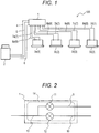
- Fig. 1 illustrates a system diagram of an air conditioner 100 including a refrigerant flow path switching unit 1 of the present embodiment.
- the air conditioner 100 is a simultaneous cooling-heating type multi air conditioner configured so that cooling and heating can be simultaneously performed for each indoor unit 3.
- the air conditioner 100 includes the refrigerant flow path switching unit 1, an outdoor unit 2, the multiple indoor units 3 (3a, 3b, 3c, 3d), a first high/low pressure gas pipe 4, a first low pressure gas pipe 5, a first liquid pipe 6, first gas pipes 7 (7a, 7b, 7c, 7d), and second liquid pipes 8 (8a, 8b, 8c, 8d).
- the first high/low pressure gas pipe 4, the first low pressure gas pipe 5, and the first liquid pipe 6 connect the refrigerant flow path switching unit 1 and the outdoor unit 2.
- the first gas pipes 7 connect the refrigerant flow path switching unit 1 and the multiple indoor units 3.
- the second liquid pipes 8 connect the outdoor unit 2 and the multiple indoor units 3.
- the first high/low pressure gas pipe 4 is also called a discharge gas pipe, and the first low pressure gas pipe 5 is also called a suction gas pipe.
- the refrigerant flow path switching unit 1 and the outdoor unit 2 are connected to each other via three pipes of the first high/low pressure gas pipe 4, the first low pressure gas pipe 5, and the first liquid pipe 6, and therefore, the air conditioner 100 is a so-called three-pipe air conditioner.
- the outdoor unit 2 includes a compressor configured to compress refrigerant to be supplied to the refrigerant flow path switching unit 1, two outdoor heat exchangers (a condenser and an evaporator) configured to exchange heat between outdoor air and refrigerant, an outdoor expansion valve configured to expand refrigerant before or after (varies according to cooling-centered or heating-centered operation) heat exchange in the outdoor heat exchanger, and a four-way valve configured to switch a refrigerant flow path according to the cooling-centered or heating-centered operation.
- the first high/low pressure gas pipe 4 is configured switchable to a high pressure gas pipe or a low pressure gas pipe in the outdoor unit 2 according to a four-way valve switching direction.
- the first low pressure gas pipe 5 is connected to a suction side of the compressor.
- the first liquid pipe 6 is connected to an expansion valve side of the outdoor heat exchanger (the condenser) of the outdoor unit 2.
- the indoor unit 3 includes an indoor heat exchanger configured to exchange heat between indoor air and refrigerant, and an indoor expansion valve configured to expand refrigerant before or after (varies according to an operation mode of the indoor unit) heat exchange in the indoor heat exchanger.
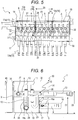
- Fig. 2 illustrates a refrigerant circuit diagram of the independent-type refrigerant flow path switching unit 1.
- the independent-type refrigerant flow path switching unit 1 includes a second high/low pressure gas pipe 9, a second low pressure gas pipe 10, a high/low pressure electric valve 11, a low pressure electric valve 12, and a second gas pipe 13.
- the second high/low pressure gas pipe 9 is connected to the first high/low pressure gas pipe 4
- the second low pressure gas pipe 10 is connected to the first low pressure gas pipe 5
- the second gas pipe 13 is connected to the first gas pipes 7.
- the high/low pressure electric valve 11 and the low pressure electric valve 12 are opened, and a flow in the second high/low pressure gas pipe 9 and the second low pressure gas pipe 10 is allowed.
- a case where a flow in the second high/low pressure gas pipe 9 is allowed is a case where all of the indoor units 3 perform the cooling operation.
- it is controlled such that the high/low pressure electric valve 11 is closed to inhibit a flow in the second high/low pressure gas pipe 9 and the second gas pipe 13.
- the refrigerant flow path switching unit 1 connected to the indoor units 3 performing heating operation, it is controlled such that the high/low pressure electric valve 11 is opened to allow a flow in the high/low pressure gas pipe 9 and the second gas pipe 13 and the low pressure electric valve 12 is closed to inhibit a flow in the low pressure gas pipe 10 and the second gas pipe 13. Then, a flow from the second gas pipe 13 to the indoor units 3 via the first gas pipes 7 is allowed.
- This refrigerant circuit of the refrigerant flow path switching unit 1 is taken as a refrigerant flow path switching circuit 14.
- the refrigerant circuit diagram of the refrigerant flow path switching circuit 1 illustrated in Fig. 2 shows such an independent type that a single refrigerant flow path switching unit 1 is provided for each indoor unit 3.
- an assembly type has been known, in which multiple indoor units 3 are connected to a single refrigerant flow path switching unit 1.
- Fig. 3 illustrates a refrigerant circuit diagram of the assembly-type refrigerant flow path switching unit 1.
- Fig. 4 is a schematic view of the refrigerant flow path switching unit 1 from a lateral side, and illustrates a foam charging area.
- Fig. 5 is a schematic view of the refrigerant flow path switching unit 1 from above, and illustrates the inside of a housing 1.
- Fig. 6 is a schematic view of the refrigerant flow path switching unit 1 from a lateral side, and illustrates the inside of the housing 1.
- the assembly-type refrigerant flow path switching unit 1 includes the housing 30 having a rectangular parallelepiped outer shape, an electric box 40 where a control board is built in, a refrigerant flow path switching circuit assembly 15, a liquid pipe assembly 16.
- the housing 30 includes a pair of first side plates 31 parallel to a longitudinal direction, a pair of second side plates 32 parallel to a lateral direction, a bottom plate 33, an upper plate 34, and an inner plate 35.
- first divider plates 18 18a, 18b
- second divider plate 17 has, as viewed laterally, a portion extending perpendicularly from the bottom plate 33, a portion extending perpendicularly from the side plate 31 on the opposite side of the electric box 40, and a portion connecting both of these portions.
- the second divider plate 17 extends along the longitudinal direction of the housing 30.
- the second divider plate 17 By the second divider plate 17, an internal space of the housing 30 is divided into a first region X and a second region Y.
- the second region Y is defined by the second divider plate 17, the bottom plate 33, the first side plate 31, and the pair of second side plates.
- the second region Y is formed with a simple configuration.
- the electric box 40 is connected to one first side surface 31.
- the refrigerant flow path switching assembly 15 is arranged in the first region X, and the liquid pipe assembly 16 is arranged in the second region Y.
- the refrigerant flow path switching circuit assembly 15 includes a high/low pressure common gas pipe 27, a low pressure common gas pipe 28, and multiple refrigerant flow path switching circuits 14 (14a).
- the refrigerant flow path switching circuit 14 includes the second high/low pressure gas pipe 9, the second low pressure gas pipe 10, the high/low pressure electric valve 11 (11a), the low pressure electric valve 12 (14a), and the second gas pipe 13.
- the high/low pressure common gas pipe 27 extends along the longitudinal direction of the housing 30, and is connected to the second high/low pressure gas pipe 9 of each refrigerant flow path switching circuit 14.
- the low pressure common gas pipe 28 extends along the longitudinal direction of the housing 30, and is connected to the second low pressure gas pipe 10 of each refrigerant flow path switching circuit 14.
- each refrigerant flow path switching circuit 14 extends along the lateral direction of the housing 30, and is connected to the first gas pipes 7.
- the refrigerant flow path switching circuit assembly 15 is configured such that 12 refrigerant flow path switching circuits 14 are coupled to each other along the longitudinal direction.
- the second gas pipe 13 passes above the second divider plate 17, and penetrates the side plate 31.
- each first divider plate 18 (18a, 18b) is provided between adjacent ones of the refrigerant flow path switching circuits 14, and is provided for every multiple (in the present embodiment, four) refrigerant flow path switching circuits 14.
- the internal space of the housing 30 is divided into substantially cubic spaces.
- each first divider plate 18 extends from the second divider plate 17 to the first side plate 31 on an electric box 40 side.
- the internal space of the housing 30 is divided by the first divider plates 18, the second divider plate 17, and the upper plate 34, and substantially cubic spaces A are formed.
- the upper plate 34 is provided to cover the refrigerant flow path switching circuit assembly 15 from above.
- At least part of the second high/low pressure gas pipe 9, at least part of the second low pressure gas pipe 10, the high/low pressure electric valve 11, the low pressure electric valve 12, and at least part of the second gas pipe 13 are positioned at an upper portion of the space A, and the heights of the first divider plates 18 and the second divider plate 17 are set lower than that of the upper portion of the space A.
- cutouts 18c opening on an upper side are formed at the first divider plates 18, and the low pressure common gas pipe 28 penetrates lower portions of the cutouts 18c.
- Heat insulating materials 26 are bonded to fill the cutouts 18c.
- an area indicated by a dot-line portion 20 in the space A is filled with a foaming agent (a heat insulating member) 21.
- a foaming agent a heat insulating member
- the inside of the space A is filled with the foaming agent (the heat insulating member) 21 in such a manner that the foaming agent in the form of liquid is dripped through a hole formed at the inner plate 35 and is expanded thereafter.
- a liquid mixture of INS-A and RIGID-200 is used as the foaming agent.
- the liquid pipe assembly 16 includes a common liquid pipe 16a and the multiple second liquid pipes 8 (8a), and is positioned below the second gas pipe 13.
- the common liquid pipe 16a extends along the longitudinal direction of the housing 30.
- Each second liquid pipe 8 is connected to the common liquid pipe 16a, and extends along the lateral direction of the housing 30.
- the multiple second liquid pipes 8 of the liquid pipe assembly 16 are not connected to the refrigerant flow path switching circuits 14 of the refrigerant flow path switching circuit assembly 15. That is, the refrigerant flow path switching circuit assembly 15 and the liquid pipe assembly 16 are configured independently of each other.
- the liquid pipe assembly 16 does not relate to switching of a refrigerant flow, and therefore, the liquid pipe assembly 16 is not necessarily provided in the refrigerant flow path switching unit 1.
- the assembly type includes the multiple indoor units 3, and for this reason, in site work, it is necessary to check which indoor unit 3 is to be connected to which pipe. This leads to poor workability.
- the liquid pipe assembly 16 is arranged in the refrigerant flow path switching unit 1 so that a work location to be focused can be determined and the first gas pipes 7 can be processed simultaneously. Thus, workability can be enhanced without time and effort for a checking process. This is because the liquid pipe assembly 16 is arranged in the refrigerant flow path switching unit 1.
- the second liquid pipes 8 have a high pipe temperature, and therefore, there are less concerns on dew condensation. For reduction of a foam charging amount and shortening of a foam charging time, foam charging is not performed. Note that although the foaming agent is not charged, the periphery of the second liquid pipes 8 may be covered with a heat insulating member (e.g., EPT and polyethylene). Thus, in Fig. 4 , foam charging is not performed for a shaded portion 19 corresponding to the second region Y. As described above, foam charging is not necessarily performed for the liquid pipe assembly 16, and therefore, the refrigerant flow path switching circuit assembly 15 for which foam charging is necessary and the liquid pipe assembly 16 are separated by the second divider plate 17. That is, the refrigerant flow path switching circuit assembly 15 and the liquid pipe assembly 16 are independent from each other. Thus, the first region X and the second region Y are only simply divided by the second divider plate 17, and therefore, a simple structure can be provided.
- EPT and polyethylene e.g., polyethylene
- Each first divider plate 18 (18a, 18b) is provided between adjacent ones of the refrigerant flow path switching circuits 14, thereby forming the spaces A.
- the space in the housing 30 is large.
- the foaming agent is solidified before spreading across the entire space, leading to cavities in the housing 30. This leads to foaming failure.
- the first divider plate 18 is, for all of the refrigerant flow path switching circuits 14, provided in each portion between adjacent ones of the refrigerant flow path switching circuits 14, the space is small, and an area targeted for foam charging is also small. For this reason, the foaming agent can be charged into every corner of the space.
- the number of first divider plates 18 is great. This leads to a greater number of first divider plates 18, a greater weight, and a higher cost. Further, foam charging needs to be performed for each refrigerant flow path switching circuit 14. This leads to a longer foam charging time and lower workability.
- the refrigerant flow path switching circuit assembly 15 is divided for every multiple (four) refrigerant flow path switching circuits 14 by the first divider plates 18.
- the spaces A formed by such division are in the substantially cubic shape, and are filled with the foaming agent. Since the substantially cubic spaces A are formed as described above, the foaming agent uniformly expands each side, so that the inside of the spaces A can be filled without clearances.
- the number of first divider plates 18 can be reduced, and the number of times of foam charging and the charging amount can be reduced while charging failure is prevented.
- the refrigerant flow path switching circuit assembly 15 is divided for every four refrigerant flow path switching circuits 14 by the first divider plates 18. Since the number of times of foam charging and the charging amount can be reduced, the cost of the refrigerant flow path switching unit 1 can be reduced, and therefore, the cost of the air conditioner 100 can be reduced.
- the first divider plate 18 is lower than the height 23 of the foam charging area (the space A).
- the first divider plates 18 may be placed in an upper-to-lower direction to form completely-separated spaces.
- the refrigerant flow path switching circuit assembly 15 is not divided for each refrigerant flow path switching circuit 14, but is divided for every multiple refrigerant flow path switching circuits 14 to form the substantially rectangular parallelepiped spaces A.
- a width 25 in the case of division for every multiple refrigerant flow path switching circuits 14 is greater than a width 24 in the case of division for each refrigerant flow path switching circuit 14, and therefore, the amount of foaming agent leaking to adjacent refrigerant flow path switching circuits 14 upon foam charging can be reduced.
- the inside of the housing 30 is divided into the first region X and the second region Y by the second divider plate 17, and only the first region X is filled with the foaming agent 21 as the heat insulating member.
- the amount of foaming agent to be charged can be reduced. Consequently, the low-cost refrigerant flow path switching unit 1 can be provided, and therefore, the cost of the air conditioner 100 can be reduced.
- the refrigerant flow path switching circuit assembly 15 is divided for every four refrigerant flow path switching circuits 14 by the first divider plates 18 to form the substantially cubic spaces A.
- the number of refrigerant flow path switching circuits 14 is not limited to four, but may be any number as long as the substantially cubic spaces can be formed.
Landscapes
- Engineering & Computer Science (AREA)
- Mechanical Engineering (AREA)
- General Engineering & Computer Science (AREA)
- Physics & Mathematics (AREA)
- Thermal Sciences (AREA)
- Chemical & Material Sciences (AREA)
- Combustion & Propulsion (AREA)
- Fluid Mechanics (AREA)
- Other Air-Conditioning Systems (AREA)
- Compression-Type Refrigeration Machines With Reversible Cycles (AREA)
Abstract
Description
- The present invention relates to a refrigerant flow path switching unit, and relates to a refrigerant flow path switching unit provided with a structure for dividing the inside of the unit and an air conditioner.
- A so-called multi air conditioner has been known, in which an indoor unit is provided for each room and cooling and heating can be performed at the same time independently for the indoor units. This air conditioner is used at a building, a commercial facility, and the like., for example. In the multi air conditioner, a refrigerant flow direction is controlled for each indoor unit, and cooling and heating in each indoor unit are changeable.
- In the multi air conditioner, a refrigerant flow path switching unit configured to switch the direction of a refrigerant flow to each indoor unit is provided between an outdoor unit and each of the multiple indoor units. Two types of refrigerant flow path switching units including an assembly type that multiple indoor units are connected to a single refrigerant flow path switching unit and an independent type that a single refrigerant flow path switching unit is provided for each indoor unit have been known as the refrigerant flow path switching unit.
- Of these units, the former assembly-type refrigerant flow path switching unit is specifically connected to a high/low pressure gas pipe and a low pressure gas pipe connected to the outdoor unit, a gas pipe connected to each indoor unit, and a liquid pipe connected to each indoor unit as an assembly different from the gas pipe. Moreover, electric valves are provided in the middle of the high/low pressure gas pipe and the low pressure gas pipe. Opening/closing of these valves is controlled, so that the refrigerant flow direction in each indoor unit can be controlled.
- The refrigerant flow path switching unit is mainly placed in a ceiling, and the inside of the unit needs to be thermally insulated to prevent leakage of condensation water from the unit through the ceiling. Thus, a structure is preferable, in which the inside of the unit is filled with a heat insulating material such as a foaming agent to enhance heat insulating properties and prevent dew condensation.
- However, in the assembly-type refrigerant flow path switching unit, when a common space in a housing is provided, the internal space is large. Thus, even when an attempt is made to form the heat insulating material by injection of a liquid foaming agent into the housing, the foaming agent is solidified before spreading across the entirety of the inside of the housing, and cavities might be formed in the housing. With the cavities in the housing, dew condensation might occur on pipe surfaces at these portions, and water droplets might drop from the housing.
- For solving such a problem, in, e.g., a refrigerant flow path switching unit of
Patent Literature 1, divider plates are arranged in a space in a casing in which multiple refrigerant pipe assemblies are arranged, and divide the space in the casing for each refrigerant pipe assembly. Moreover, each refrigerant pipe assembly is filled with a foaming agent for prevention of dew condensation. - PATENT LITERATURE 1: Japanese Patent No.
5282666 - However, in the refrigerant flow path switching unit described in
Patent Literature 1, the divider plates divide the space for each refrigerant pipe assembly to form spaces. This leads to an increase in the number of divider plates and greater housing dimensions in addition to a weight increase, an increase in the number of times of foam charging, and a cost increase. Moreover, in the refrigerant flow path switching unit described inPatent Literature 1, foam charging is performed for each refrigerant pipe assembly to fill an entire area in the casing. This leads to a greater amount of charged foaming agent. - Thus, the present invention is intended to provide a refrigerant flow path switching unit configured so that the inside of a housing can be filled with a foaming agent without clearances and the number of times of foam charging and a charging amount can be reduced and an air conditioner. Moreover, the present invention is further intended to provide a refrigerant flow path switching unit configured so that a foaming agent charging amount can be reduced while occurrence of dew condensation is reduced and an air conditioner.
- For accomplishing the above-described objectives, a refrigerant flow path switching unit according to one embodiment of the present invention is a refrigerant flow path switching unit arranged between an outdoor unit and each of multiple indoor units to control a refrigerant flow. The refrigerant flow path switching unit includes a housing; a refrigerant flow path switching circuit assembly arranged in the housing and having multiple refrigerant flow path switching circuits, each refrigerant flow path switching circuit including a high/low pressure gas pipe, a low pressure gas pipe, a high/low pressure electric valve provided at the high/low pressure gas pipe, and a low pressure electric valve provided at the low pressure gas pipe; a liquid pipe assembly arranged in the housing and having multiple liquid pipes connected to the multiple indoor units; and a first divider plate provided between adjacent ones of the refrigerant flow path switching circuits in the housing and configured to divide an internal space of the housing. A space divided by the first divider plate is in a substantially cubic shape, and the divided space is filled with a foaming agent.
- Moreover, a refrigerant flow path switching unit according to one embodiment of the present invention is a refrigerant flow path switching unit arranged between an outdoor unit and each of multiple indoor units to control a refrigerant flow. The refrigerant flow path switching unit includes a housing including a first region and a second region; a refrigerant flow path switching circuit assembly arranged in the first region and having multiple refrigerant flow path switching circuits, each refrigerant flow path switching circuit including a high/low pressure gas pipe, a low pressure gas pipe, a high/low pressure electric valve provided at the high/low pressure gas pipe, and a low pressure electric valve provided at the low pressure gas pipe; a liquid pipe assembly arranged in the second region and having multiple liquid pipes connected to the multiple indoor units; a divider plate configured to separate the first region and the second region; and a heat insulating member provided in the first region.
- According to the present invention, a refrigerant flow path switching unit configured so that the inside of a housing can be filled with a foaming agent without clearances and the number of times of foam charging and a charging amount can be reduced and an air conditioner can be provided. Moreover, according to the present invention, a refrigerant flow path switching unit configured so that a foaming agent charging amount can be reduced while occurrence of dew condensation is reduced and an air conditioner can be provided.
-
-
Fig. 1 illustrates an entire configuration diagram of an air conditioning system including a refrigerant flow path switching unit. -
Fig. 2 illustrates a refrigerant circuit diagram of an independent-type refrigerant flow path switching unit. -
Fig. 3 illustrates a refrigerant circuit diagram of an assembly-type refrigerant flow path switching unit. -
Fig. 4 is a schematic view of the refrigerant flow path switching unit from a lateral side, and illustrates a foam charging area. -
Fig. 5 is a schematic view of the refrigerant flow path switching unit from above, and illustrates the inside of a housing. -
Fig. 6 is a schematic view of the refrigerant flow path switching unit from a lateral side, and illustrates the inside of the housing. - Hereinafter, an embodiment (the present embodiment) of the present invention will be described with reference to the drawings. Note that each figure is schematic, and for the sake of easy grasping of the present invention, some of members might be omitted or simplified as necessary without departing from the gist of the present invention or might be visualized for illustrating an internal structure.
-
Fig. 1 illustrates a system diagram of anair conditioner 100 including a refrigerant flowpath switching unit 1 of the present embodiment. - The
air conditioner 100 is a simultaneous cooling-heating type multi air conditioner configured so that cooling and heating can be simultaneously performed for eachindoor unit 3. - The
air conditioner 100 includes the refrigerant flowpath switching unit 1, anoutdoor unit 2, the multiple indoor units 3 (3a, 3b, 3c, 3d), a first high/lowpressure gas pipe 4, a first lowpressure gas pipe 5, a firstliquid pipe 6, first gas pipes 7 (7a, 7b, 7c, 7d), and second liquid pipes 8 (8a, 8b, 8c, 8d). The first high/lowpressure gas pipe 4, the first lowpressure gas pipe 5, and the firstliquid pipe 6 connect the refrigerant flowpath switching unit 1 and theoutdoor unit 2. Thefirst gas pipes 7 connect the refrigerant flowpath switching unit 1 and the multipleindoor units 3. The secondliquid pipes 8 connect theoutdoor unit 2 and the multipleindoor units 3. - The first high/low
pressure gas pipe 4 is also called a discharge gas pipe, and the first lowpressure gas pipe 5 is also called a suction gas pipe. Moreover, the refrigerant flowpath switching unit 1 and theoutdoor unit 2 are connected to each other via three pipes of the first high/lowpressure gas pipe 4, the first lowpressure gas pipe 5, and the firstliquid pipe 6, and therefore, theair conditioner 100 is a so-called three-pipe air conditioner. - Although not shown in the figure, the
outdoor unit 2 includes a compressor configured to compress refrigerant to be supplied to the refrigerant flowpath switching unit 1, two outdoor heat exchangers (a condenser and an evaporator) configured to exchange heat between outdoor air and refrigerant, an outdoor expansion valve configured to expand refrigerant before or after (varies according to cooling-centered or heating-centered operation) heat exchange in the outdoor heat exchanger, and a four-way valve configured to switch a refrigerant flow path according to the cooling-centered or heating-centered operation. Note that the first high/lowpressure gas pipe 4 is configured switchable to a high pressure gas pipe or a low pressure gas pipe in theoutdoor unit 2 according to a four-way valve switching direction. The first lowpressure gas pipe 5 is connected to a suction side of the compressor. The firstliquid pipe 6 is connected to an expansion valve side of the outdoor heat exchanger (the condenser) of theoutdoor unit 2. - Further, although not shown in the figure, the
indoor unit 3 includes an indoor heat exchanger configured to exchange heat between indoor air and refrigerant, and an indoor expansion valve configured to expand refrigerant before or after (varies according to an operation mode of the indoor unit) heat exchange in the indoor heat exchanger. - These components are connected to each other via the pipes, and refrigerant flows in the pipes. In this manner, a refrigeration cycle is formed between the
outdoor unit 2 and eachindoor unit 3. Specifically, in the refrigerant flowpath switching unit 1 arranged between theoutdoor unit 2 and eachindoor unit 3, a flow direction of refrigerant to be supplied from theoutdoor unit 2 to theindoor unit 3 is controlled, so that cooling and heating can be performed at the same time independently for theindoor units 3. - Next, the refrigerant flow
path switching unit 1 will be described. -
Fig. 2 illustrates a refrigerant circuit diagram of the independent-type refrigerant flowpath switching unit 1. - As illustrated in
Fig. 2 , the independent-type refrigerant flowpath switching unit 1 includes a second high/lowpressure gas pipe 9, a second lowpressure gas pipe 10, a high/low pressureelectric valve 11, a low pressureelectric valve 12, and asecond gas pipe 13. The second high/lowpressure gas pipe 9 is connected to the first high/lowpressure gas pipe 4, the second lowpressure gas pipe 10 is connected to the first lowpressure gas pipe 5, and thesecond gas pipe 13 is connected to thefirst gas pipes 7. In the refrigerant flowpath switching unit 1 connected to theindoor units 3 performing cooling operation, the high/low pressureelectric valve 11 and the low pressureelectric valve 12 are opened, and a flow in the second high/lowpressure gas pipe 9 and the second lowpressure gas pipe 10 is allowed. Note that a case where a flow in the second high/lowpressure gas pipe 9 is allowed is a case where all of theindoor units 3 perform the cooling operation. In simultaneous cooling-heating operation, it is controlled such that the high/low pressureelectric valve 11 is closed to inhibit a flow in the second high/lowpressure gas pipe 9 and thesecond gas pipe 13. - In the refrigerant flow
path switching unit 1 connected to theindoor units 3 performing heating operation, it is controlled such that the high/low pressureelectric valve 11 is opened to allow a flow in the high/lowpressure gas pipe 9 and thesecond gas pipe 13 and the low pressureelectric valve 12 is closed to inhibit a flow in the lowpressure gas pipe 10 and thesecond gas pipe 13. Then, a flow from thesecond gas pipe 13 to theindoor units 3 via thefirst gas pipes 7 is allowed. This refrigerant circuit of the refrigerant flowpath switching unit 1 is taken as a refrigerant flowpath switching circuit 14. - The refrigerant circuit diagram of the refrigerant flow
path switching circuit 1 illustrated inFig. 2 shows such an independent type that a single refrigerant flowpath switching unit 1 is provided for eachindoor unit 3. On the other hand, an assembly type has been known, in which multipleindoor units 3 are connected to a single refrigerant flowpath switching unit 1. - Next, the assembly-type refrigerant flow
path switching unit 1 will be described based onFigs. 3 to 6 . -
Fig. 3 illustrates a refrigerant circuit diagram of the assembly-type refrigerant flowpath switching unit 1.Fig. 4 is a schematic view of the refrigerant flowpath switching unit 1 from a lateral side, and illustrates a foam charging area.Fig. 5 is a schematic view of the refrigerant flowpath switching unit 1 from above, and illustrates the inside of ahousing 1.Fig. 6 is a schematic view of the refrigerant flowpath switching unit 1 from a lateral side, and illustrates the inside of thehousing 1. - As illustrated in
Figs. 3 to 6 , the assembly-type refrigerant flowpath switching unit 1 includes thehousing 30 having a rectangular parallelepiped outer shape, anelectric box 40 where a control board is built in, a refrigerant flow path switchingcircuit assembly 15, aliquid pipe assembly 16. - As illustrated in
Figs. 4 and5 , thehousing 30 includes a pair offirst side plates 31 parallel to a longitudinal direction, a pair ofsecond side plates 32 parallel to a lateral direction, abottom plate 33, anupper plate 34, and aninner plate 35. In thehousing 30, multiple first divider plates 18 (18a, 18b) and asecond divider plate 17 are provided. Thesecond divider plate 17 has, as viewed laterally, a portion extending perpendicularly from thebottom plate 33, a portion extending perpendicularly from theside plate 31 on the opposite side of theelectric box 40, and a portion connecting both of these portions. Thesecond divider plate 17 extends along the longitudinal direction of thehousing 30. By thesecond divider plate 17, an internal space of thehousing 30 is divided into a first region X and a second region Y. The second region Y is defined by thesecond divider plate 17, thebottom plate 33, thefirst side plate 31, and the pair of second side plates. Thus, the second region Y is formed with a simple configuration. Moreover, theelectric box 40 is connected to onefirst side surface 31. - The refrigerant flow
path switching assembly 15 is arranged in the first region X, and theliquid pipe assembly 16 is arranged in the second region Y. - The refrigerant flow path switching
circuit assembly 15 includes a high/low pressurecommon gas pipe 27, a low pressurecommon gas pipe 28, and multiple refrigerant flow path switching circuits 14 (14a). As described above, the refrigerant flowpath switching circuit 14 includes the second high/lowpressure gas pipe 9, the second lowpressure gas pipe 10, the high/low pressure electric valve 11 (11a), the low pressure electric valve 12 (14a), and thesecond gas pipe 13. The high/low pressurecommon gas pipe 27 extends along the longitudinal direction of thehousing 30, and is connected to the second high/lowpressure gas pipe 9 of each refrigerant flowpath switching circuit 14. The low pressurecommon gas pipe 28 extends along the longitudinal direction of thehousing 30, and is connected to the second lowpressure gas pipe 10 of each refrigerant flowpath switching circuit 14. Thesecond gas pipe 13 of each refrigerant flowpath switching circuit 14 extends along the lateral direction of thehousing 30, and is connected to thefirst gas pipes 7. InFig. 3 , the refrigerant flow path switchingcircuit assembly 15 is configured such that 12 refrigerant flowpath switching circuits 14 are coupled to each other along the longitudinal direction. Thesecond gas pipe 13 passes above thesecond divider plate 17, and penetrates theside plate 31. - As illustrated in
Figs. 3 and5 , each first divider plate 18 (18a, 18b) is provided between adjacent ones of the refrigerant flowpath switching circuits 14, and is provided for every multiple (in the present embodiment, four) refrigerant flowpath switching circuits 14. By thefirst divider plates 18, the internal space of thehousing 30 is divided into substantially cubic spaces. Moreover, eachfirst divider plate 18 extends from thesecond divider plate 17 to thefirst side plate 31 on anelectric box 40 side. In the present embodiment, the internal space of thehousing 30 is divided by thefirst divider plates 18, thesecond divider plate 17, and theupper plate 34, and substantially cubic spaces A are formed. Moreover, theupper plate 34 is provided to cover the refrigerant flow path switchingcircuit assembly 15 from above. - In the space A, at least part of the second high/low
pressure gas pipe 9, at least part of the second lowpressure gas pipe 10, the high/low pressureelectric valve 11, the low pressureelectric valve 12, and at least part of thesecond gas pipe 13 are positioned at an upper portion of the space A, and the heights of thefirst divider plates 18 and thesecond divider plate 17 are set lower than that of the upper portion of the space A. Moreover, as illustrated inFig. 6 ,cutouts 18c opening on an upper side are formed at thefirst divider plates 18, and the low pressurecommon gas pipe 28 penetrates lower portions of thecutouts 18c. Heat insulating materials 26 (shaded portions) are bonded to fill thecutouts 18c. - As illustrated in
Fig. 4 , an area indicated by a dot-line portion 20 in the space A is filled with a foaming agent (a heat insulating member) 21. For example, the inside of the space A is filled with the foaming agent (the heat insulating member) 21 in such a manner that the foaming agent in the form of liquid is dripped through a hole formed at theinner plate 35 and is expanded thereafter. For example, a liquid mixture of INS-A and RIGID-200 is used as the foaming agent. - The
liquid pipe assembly 16 includes acommon liquid pipe 16a and the multiple second liquid pipes 8 (8a), and is positioned below thesecond gas pipe 13. Thecommon liquid pipe 16a extends along the longitudinal direction of thehousing 30. Each secondliquid pipe 8 is connected to thecommon liquid pipe 16a, and extends along the lateral direction of thehousing 30. The multiple secondliquid pipes 8 of theliquid pipe assembly 16 are not connected to the refrigerant flowpath switching circuits 14 of the refrigerant flow path switchingcircuit assembly 15. That is, the refrigerant flow path switchingcircuit assembly 15 and theliquid pipe assembly 16 are configured independently of each other. - As illustrated in
Figs. 3 and 4 , theliquid pipe assembly 16 does not relate to switching of a refrigerant flow, and therefore, theliquid pipe assembly 16 is not necessarily provided in the refrigerant flowpath switching unit 1. However, the assembly type includes the multipleindoor units 3, and for this reason, in site work, it is necessary to check whichindoor unit 3 is to be connected to which pipe. This leads to poor workability. For these reasons, theliquid pipe assembly 16 is arranged in the refrigerant flowpath switching unit 1 so that a work location to be focused can be determined and thefirst gas pipes 7 can be processed simultaneously. Thus, workability can be enhanced without time and effort for a checking process. This is because theliquid pipe assembly 16 is arranged in the refrigerant flowpath switching unit 1. - The second
liquid pipes 8 have a high pipe temperature, and therefore, there are less concerns on dew condensation. For reduction of a foam charging amount and shortening of a foam charging time, foam charging is not performed. Note that although the foaming agent is not charged, the periphery of the secondliquid pipes 8 may be covered with a heat insulating member (e.g., EPT and polyethylene). Thus, inFig. 4 , foam charging is not performed for a shadedportion 19 corresponding to the second region Y. As described above, foam charging is not necessarily performed for theliquid pipe assembly 16, and therefore, the refrigerant flow path switchingcircuit assembly 15 for which foam charging is necessary and theliquid pipe assembly 16 are separated by thesecond divider plate 17. That is, the refrigerant flow path switchingcircuit assembly 15 and theliquid pipe assembly 16 are independent from each other. Thus, the first region X and the second region Y are only simply divided by thesecond divider plate 17, and therefore, a simple structure can be provided. - Each first divider plate 18 (18a, 18b) is provided between adjacent ones of the refrigerant flow
path switching circuits 14, thereby forming the spaces A. In a case where nofirst divider plates 18 are provided, the space in thehousing 30 is large. For this reason, the foaming agent is solidified before spreading across the entire space, leading to cavities in thehousing 30. This leads to foaming failure. When thefirst divider plate 18 is, for all of the refrigerant flowpath switching circuits 14, provided in each portion between adjacent ones of the refrigerant flowpath switching circuits 14, the space is small, and an area targeted for foam charging is also small. For this reason, the foaming agent can be charged into every corner of the space. However, the number offirst divider plates 18 is great. This leads to a greater number offirst divider plates 18, a greater weight, and a higher cost. Further, foam charging needs to be performed for each refrigerant flowpath switching circuit 14. This leads to a longer foam charging time and lower workability. - On the other hand, in the present embodiment, the refrigerant flow path switching
circuit assembly 15 is divided for every multiple (four) refrigerant flowpath switching circuits 14 by thefirst divider plates 18. In this manner, the spaces A formed by such division are in the substantially cubic shape, and are filled with the foaming agent. Since the substantially cubic spaces A are formed as described above, the foaming agent uniformly expands each side, so that the inside of the spaces A can be filled without clearances. Thus, the number offirst divider plates 18 can be reduced, and the number of times of foam charging and the charging amount can be reduced while charging failure is prevented. The upper view of the refrigerant flowpath switching unit 1 ofFig. 5 shows that the refrigerant flow path switchingcircuit assembly 15 is divided for every four refrigerant flowpath switching circuits 14 by thefirst divider plates 18. Since the number of times of foam charging and the charging amount can be reduced, the cost of the refrigerant flowpath switching unit 1 can be reduced, and therefore, the cost of theair conditioner 100 can be reduced. - Moreover, as illustrated in
Fig. 6 , it is configured such that theheight 22 of thefirst divider plate 18 is lower than theheight 23 of the foam charging area (the space A). For charging the foaming agent into every corner, thefirst divider plates 18 may be placed in an upper-to-lower direction to form completely-separated spaces. In the present embodiment, the refrigerant flow path switchingcircuit assembly 15 is not divided for each refrigerant flowpath switching circuit 14, but is divided for every multiple refrigerant flowpath switching circuits 14 to form the substantially rectangular parallelepiped spaces A. Thus, as illustrated inFig. 5 , awidth 25 in the case of division for every multiple refrigerant flowpath switching circuits 14 is greater than awidth 24 in the case of division for each refrigerant flowpath switching circuit 14, and therefore, the amount of foaming agent leaking to adjacent refrigerant flowpath switching circuits 14 upon foam charging can be reduced. - Thus, a proper amount of liquid foaming agent is dripped in the space A, so that the amount of foaming agent leaking to adjacent spaces A can be, without the need for completely separating the spaces A, reduced while the foaming agent can be charged into every corner of the space A. With this configuration, it is not necessary to completely separate the spaces A adjacent to each other by the
first divider plates 18, and therefore, an increase in the number of divider plates and a cost increase can be suppressed without the need for increasing divider plates from an upper direction. Note that theheat insulating materials 26 are bonded to thecutouts 18c of thedivider plates 18, and therefore, leakage of the foaming agent to adjacent spaces A is prevented. - The inside of the
housing 30 is divided into the first region X and the second region Y by thesecond divider plate 17, and only the first region X is filled with the foamingagent 21 as the heat insulating member. Thus, the amount of foaming agent to be charged can be reduced. Consequently, the low-cost refrigerant flowpath switching unit 1 can be provided, and therefore, the cost of theair conditioner 100 can be reduced. - Note that the present invention is not limited to the above-described embodiment. Those skilled in the art can make various additions, changes, and the like within the scope of the present invention.
- In the above-described embodiment, the refrigerant flow path switching
circuit assembly 15 is divided for every four refrigerant flowpath switching circuits 14 by thefirst divider plates 18 to form the substantially cubic spaces A. However, the number of refrigerant flowpath switching circuits 14 is not limited to four, but may be any number as long as the substantially cubic spaces can be formed. -
- 1
- Refrigerant flow path switching unit
- 2
- Outdoor unit
- 3
- Indoor unit
- 8
- Second liquid pipe
- 9
- Second high/low pressure gas pipe
- 10
- Second low pressure gas pipe
- 11
- High/low pressure electric valve
- 12
- Low pressure electric valve
- 13
- Second gas pipe
- 14
- Refrigerant flow path switching circuit
- 15
- Refrigerant flow path switching circuit assembly
- 16
- Liquid pipe assembly
- 17
- Second divider plate
- 18
- First divider plate
- 21
- Foaming agent
Claims (11)
- A refrigerant flow path switching unit arranged between an outdoor unit and each of multiple indoor units to control a refrigerant flow, comprising:a housing;a refrigerant flow path switching circuit assembly arranged in the housing and having multiple refrigerant flow path switching circuits, each refrigerant flow path switching circuit including a high/low pressure gas pipe, a low pressure gas pipe, a high/low pressure electric valve provided at the high/low pressure gas pipe, and a low pressure electric valve provided at the low pressure gas pipe;a liquid pipe assembly arranged in the housing and having multiple liquid pipes connected to the multiple indoor units; anda first divider plate provided between adjacent ones of the refrigerant flow path switching circuits in the housing and configured to divide an internal space of the housing,wherein a space divided by the first divider plate is in a substantially cubic shape, and the divided space is filled with a foaming agent.
- The refrigerant flow path switching unit according to claim 1, wherein
the first divider plate is provided for every multiple refrigerant flow path switching circuits. - The refrigerant flow path switching unit according to claim 2, wherein
the first divider plate is provided for every four refrigerant flow path switching circuits. - The refrigerant flow path switching unit according to any one of claims 1 to 3, further comprising:a second divider plate provided in the housing and configured to separate the refrigerant flow path switching circuit assembly and the liquid pipe assembly, whereinthe internal space of the housing is divided in a substantially cubic shape by the first divider plate and the second divider plate, and a divided space is filled with the foaming agent.
- The refrigerant flow path switching unit according to any one of claims 1 to 4, wherein
in each refrigerant flow path switching circuit, part of the high/low pressure gas pipe, part of the low pressure gas pipe, the high/low pressure electric valve, and the low pressure electric valve are positioned at an upper portion of the divided space, and
a height of the first divider plate is set lower than a position of the upper portion. - An air conditioner comprising:an outdoor unit;multiple indoor units; andthe refrigerant flow path switching unit according to any one of claims 1 to 5, the refrigerant flow path switching unit being arranged between the outdoor unit and each of the multiple indoor units to control a refrigerant flow.
- A refrigerant flow path switching unit arranged between an outdoor unit and each of multiple indoor units to control a refrigerant flow, comprising:a housing including a first region and a second region;a refrigerant flow path switching circuit assembly arranged in the first region and having multiple refrigerant flow path switching circuits, each refrigerant flow path switching circuit including a high/low pressure gas pipe, a low pressure gas pipe, a high/low pressure electric valve provided at the high/low pressure gas pipe, and a low pressure electric valve provided at the low pressure gas pipe;a liquid pipe assembly arranged in the second region and having multiple liquid pipes connected to the multiple indoor units;a divider plate configured to separate the first region and the second region; anda heat insulating member provided in the first region.
- The refrigerant flow path switching unit according to claim 7, wherein
the heat insulating member is provided only at a periphery of the liquid pipes in the second region. - The refrigerant flow path switching unit according to claim 7 or 8, wherein
the refrigerant flow path switching circuit assembly and the liquid pipe assembly are independent from each other in the housing. - The refrigerant flow path switching unit according to any one of claims 7 to 9, wherein
the second region is defined by the divider plate and bottom and side plates of the housing. - An air conditioner comprising:an outdoor unit;multiple indoor units; andthe refrigerant flow path switching unit according to any one of claims 7 to 10, the refrigerant flow path switching unit being arranged between the outdoor unit and each of the multiple indoor units to control a refrigerant flow.
Applications Claiming Priority (3)
| Application Number | Priority Date | Filing Date | Title |
|---|---|---|---|
| JP2017087903 | 2017-04-27 | ||
| JP2017087900 | 2017-04-27 | ||
| PCT/JP2018/014740 WO2018198726A1 (en) | 2017-04-27 | 2018-04-06 | Refrigerant channel switching unit and air conditioner |
Publications (3)
| Publication Number | Publication Date |
|---|---|
| EP3617613A1 true EP3617613A1 (en) | 2020-03-04 |
| EP3617613A4 EP3617613A4 (en) | 2021-01-13 |
| EP3617613B1 EP3617613B1 (en) | 2023-03-22 |
Family
ID=63919036
Family Applications (1)
| Application Number | Title | Priority Date | Filing Date |
|---|---|---|---|
| EP18791132.6A Active EP3617613B1 (en) | 2017-04-27 | 2018-04-06 | Refrigerant channel switching unit and air conditioner |
Country Status (5)
| Country | Link |
|---|---|
| US (1) | US10907871B2 (en) |
| EP (1) | EP3617613B1 (en) |
| JP (1) | JP6591682B2 (en) |
| CN (1) | CN109154458B (en) |
| WO (1) | WO2018198726A1 (en) |
Families Citing this family (5)
| Publication number | Priority date | Publication date | Assignee | Title |
|---|---|---|---|---|
| JP6721546B2 (en) * | 2017-07-21 | 2020-07-15 | ダイキン工業株式会社 | Refrigeration equipment |
| EP3889512A1 (en) * | 2017-09-29 | 2021-10-06 | Daikin Industries, Ltd. | Air conditioning system |
| JP2021063624A (en) * | 2019-10-16 | 2021-04-22 | 株式会社富士通ゼネラル | Switching unit |
| CN112178893B (en) * | 2020-09-22 | 2021-11-30 | 广东美的暖通设备有限公司 | Air conditioner, control method, and computer-readable storage medium |
| US20250085037A1 (en) * | 2023-09-11 | 2025-03-13 | Oetiker Ny, Inc. | Variable refrigerant flow assembly with quick connection and serviceable filter |
Family Cites Families (16)
| Publication number | Priority date | Publication date | Assignee | Title |
|---|---|---|---|---|
| TW330977B (en) * | 1996-06-04 | 1998-05-01 | Jinkichi Aizawa | Heat exchanger, method of reusing and recovering refrigerant thereof |
| JP3745211B2 (en) * | 2000-09-21 | 2006-02-15 | 柿沼金属精機株式会社 | Branch joint |
| CN1782622A (en) * | 2004-11-29 | 2006-06-07 | 乐金电子(天津)电器有限公司 | One dragging more air conditioner |
| JP3885817B2 (en) * | 2005-04-19 | 2007-02-28 | ダイキン工業株式会社 | Branch refrigerant relay unit and manufacturing method thereof |
| JP5282666B2 (en) * | 2009-06-09 | 2013-09-04 | ダイキン工業株式会社 | Refrigerant flow path switching device |
| CN102192624B (en) * | 2010-03-11 | 2014-11-26 | Lg电子株式会社 | Outdoor unit, distribution unit and air conditioning device including them |
| CN102893095B (en) * | 2010-05-12 | 2016-01-06 | 三菱电机株式会社 | Switching device and air conditioning device |
| JP5447231B2 (en) * | 2010-06-30 | 2014-03-19 | 株式会社富士通ゼネラル | Air conditioner refrigerant branching unit |
| CN201954856U (en) * | 2010-12-15 | 2011-08-31 | 重庆美的通用制冷设备有限公司 | Cold medium flow direction converter and flow control device |
| KR101375718B1 (en) * | 2011-02-21 | 2014-03-20 | 삼성전자주식회사 | Structure for connecting coolant pipe and air conditioner having the same |
| JP6028445B2 (en) * | 2012-01-23 | 2016-11-16 | 株式会社富士通ゼネラル | Refrigerant circuit unit |
| WO2013132543A1 (en) * | 2012-03-09 | 2013-09-12 | 三菱電機株式会社 | Flow passage switching device and air conditioning device with same |
| JP5971008B2 (en) * | 2012-07-30 | 2016-08-17 | 株式会社富士通ゼネラル | Refrigerant circuit unit |
| JP6055754B2 (en) * | 2013-12-11 | 2016-12-27 | ダイキン工業株式会社 | Refrigerant flow path switching unit and refrigeration apparatus including refrigerant flow path switching unit |
| JP6190737B2 (en) * | 2014-02-25 | 2017-08-30 | ジョンソンコントロールズ ヒタチ エア コンディショニング テクノロジー(ホンコン)リミテッド | Refrigerant flow path switching device for air conditioner |
| EP3348934B1 (en) * | 2015-09-11 | 2021-10-27 | Hitachi-Johnson Controls Air Conditioning, Inc. | Air conditioner |
-
2018
- 2018-04-06 CN CN201880000855.0A patent/CN109154458B/en active Active
- 2018-04-06 JP JP2018533704A patent/JP6591682B2/en active Active
- 2018-04-06 EP EP18791132.6A patent/EP3617613B1/en active Active
- 2018-04-06 WO PCT/JP2018/014740 patent/WO2018198726A1/en not_active Ceased
- 2018-11-27 US US16/200,889 patent/US10907871B2/en active Active
Also Published As
| Publication number | Publication date |
|---|---|
| JP6591682B2 (en) | 2019-10-16 |
| CN109154458A (en) | 2019-01-04 |
| EP3617613A4 (en) | 2021-01-13 |
| CN109154458B (en) | 2021-01-08 |
| WO2018198726A1 (en) | 2018-11-01 |
| US10907871B2 (en) | 2021-02-02 |
| US20190093931A1 (en) | 2019-03-28 |
| EP3617613B1 (en) | 2023-03-22 |
| JPWO2018198726A1 (en) | 2019-06-27 |
Similar Documents
| Publication | Publication Date | Title |
|---|---|---|
| EP3617613B1 (en) | Refrigerant channel switching unit and air conditioner | |
| EP3249309B1 (en) | Heat exchange unit for air conditioning device | |
| EP3447393B1 (en) | Heat source unit | |
| US11274838B2 (en) | Air-conditioner outdoor heat exchanger and air-conditioner including the same | |
| AU2018313441B2 (en) | Outdoor unit for refrigeration apparatus | |
| JP2016095087A (en) | Heat exchanger | |
| JP5282666B2 (en) | Refrigerant flow path switching device | |
| EP2587192B1 (en) | Air conditioner | |
| EP1655555A2 (en) | Air conditioner | |
| WO2020039513A1 (en) | Heat exchanger and air conditioner | |
| KR102080836B1 (en) | An air conditioning system | |
| US11022328B2 (en) | Heat source unit | |
| EP4427955A1 (en) | Vehicle air conditioner | |
| EP3514457B1 (en) | Heat source unit | |
| JP2016095086A (en) | Heat exchanger | |
| US20200200476A1 (en) | Heat exchanger | |
| KR20150096308A (en) | Outdoor unit of air conditioner | |
| KR20180005905A (en) | An outdoor unit and airconditioner having it | |
| US12203667B2 (en) | Air conditioner | |
| JP5575083B2 (en) | Air conditioner outdoor unit and air conditioner equipped with the outdoor unit | |
| JP2021055933A (en) | Switching unit | |
| WO2018012036A1 (en) | Refrigerant flow passage switching unit and air conditioner provided with same | |
| JP2019020043A (en) | Air conditioner outdoor unit | |
| CN121631649A (en) | Refrigerant flow path switching device and air conditioning equipment | |
| KR101669971B1 (en) | Air conditioner |
Legal Events
| Date | Code | Title | Description |
|---|---|---|---|
| STAA | Information on the status of an ep patent application or granted ep patent |
Free format text: STATUS: THE INTERNATIONAL PUBLICATION HAS BEEN MADE |
|
| PUAI | Public reference made under article 153(3) epc to a published international application that has entered the european phase |
Free format text: ORIGINAL CODE: 0009012 |
|
| STAA | Information on the status of an ep patent application or granted ep patent |
Free format text: STATUS: REQUEST FOR EXAMINATION WAS MADE |
|
| 17P | Request for examination filed |
Effective date: 20181115 |
|
| AK | Designated contracting states |
Kind code of ref document: A1 Designated state(s): AL AT BE BG CH CY CZ DE DK EE ES FI FR GB GR HR HU IE IS IT LI LT LU LV MC MK MT NL NO PL PT RO RS SE SI SK SM TR |
|
| AX | Request for extension of the european patent |
Extension state: BA ME |
|
| DAV | Request for validation of the european patent (deleted) | ||
| DAX | Request for extension of the european patent (deleted) | ||
| A4 | Supplementary search report drawn up and despatched |
Effective date: 20201211 |
|
| RIC1 | Information provided on ipc code assigned before grant |
Ipc: F25B 13/00 20060101AFI20201207BHEP Ipc: F25B 41/00 20060101ALI20201207BHEP Ipc: F24F 1/32 20110101ALI20201207BHEP |
|
| STAA | Information on the status of an ep patent application or granted ep patent |
Free format text: STATUS: EXAMINATION IS IN PROGRESS |
|
| 17Q | First examination report despatched |
Effective date: 20220715 |
|
| GRAP | Despatch of communication of intention to grant a patent |
Free format text: ORIGINAL CODE: EPIDOSNIGR1 |
|
| STAA | Information on the status of an ep patent application or granted ep patent |
Free format text: STATUS: GRANT OF PATENT IS INTENDED |
|
| INTG | Intention to grant announced |
Effective date: 20221222 |
|
| GRAS | Grant fee paid |
Free format text: ORIGINAL CODE: EPIDOSNIGR3 |
|
| GRAA | (expected) grant |
Free format text: ORIGINAL CODE: 0009210 |
|
| STAA | Information on the status of an ep patent application or granted ep patent |
Free format text: STATUS: THE PATENT HAS BEEN GRANTED |
|
| AK | Designated contracting states |
Kind code of ref document: B1 Designated state(s): AL AT BE BG CH CY CZ DE DK EE ES FI FR GB GR HR HU IE IS IT LI LT LU LV MC MK MT NL NO PL PT RO RS SE SI SK SM TR |
|
| REG | Reference to a national code |
Ref country code: GB Ref legal event code: FG4D |
|
| REG | Reference to a national code |
Ref country code: CH Ref legal event code: EP |
|
| REG | Reference to a national code |
Ref country code: DE Ref legal event code: R096 Ref document number: 602018047523 Country of ref document: DE |
|
| REG | Reference to a national code |
Ref country code: IE Ref legal event code: FG4D |
|
| REG | Reference to a national code |
Ref country code: AT Ref legal event code: REF Ref document number: 1555526 Country of ref document: AT Kind code of ref document: T Effective date: 20230415 |
|
| REG | Reference to a national code |
Ref country code: LT Ref legal event code: MG9D |
|
| REG | Reference to a national code |
Ref country code: NL Ref legal event code: MP Effective date: 20230322 |
|
| PG25 | Lapsed in a contracting state [announced via postgrant information from national office to epo] |
Ref country code: RS Free format text: LAPSE BECAUSE OF FAILURE TO SUBMIT A TRANSLATION OF THE DESCRIPTION OR TO PAY THE FEE WITHIN THE PRESCRIBED TIME-LIMIT Effective date: 20230322 Ref country code: NO Free format text: LAPSE BECAUSE OF FAILURE TO SUBMIT A TRANSLATION OF THE DESCRIPTION OR TO PAY THE FEE WITHIN THE PRESCRIBED TIME-LIMIT Effective date: 20230622 Ref country code: LV Free format text: LAPSE BECAUSE OF FAILURE TO SUBMIT A TRANSLATION OF THE DESCRIPTION OR TO PAY THE FEE WITHIN THE PRESCRIBED TIME-LIMIT Effective date: 20230322 Ref country code: LT Free format text: LAPSE BECAUSE OF FAILURE TO SUBMIT A TRANSLATION OF THE DESCRIPTION OR TO PAY THE FEE WITHIN THE PRESCRIBED TIME-LIMIT Effective date: 20230322 Ref country code: HR Free format text: LAPSE BECAUSE OF FAILURE TO SUBMIT A TRANSLATION OF THE DESCRIPTION OR TO PAY THE FEE WITHIN THE PRESCRIBED TIME-LIMIT Effective date: 20230322 |
|
| REG | Reference to a national code |
Ref country code: AT Ref legal event code: MK05 Ref document number: 1555526 Country of ref document: AT Kind code of ref document: T Effective date: 20230322 |
|
| PG25 | Lapsed in a contracting state [announced via postgrant information from national office to epo] |
Ref country code: SE Free format text: LAPSE BECAUSE OF FAILURE TO SUBMIT A TRANSLATION OF THE DESCRIPTION OR TO PAY THE FEE WITHIN THE PRESCRIBED TIME-LIMIT Effective date: 20230322 Ref country code: NL Free format text: LAPSE BECAUSE OF FAILURE TO SUBMIT A TRANSLATION OF THE DESCRIPTION OR TO PAY THE FEE WITHIN THE PRESCRIBED TIME-LIMIT Effective date: 20230322 Ref country code: GR Free format text: LAPSE BECAUSE OF FAILURE TO SUBMIT A TRANSLATION OF THE DESCRIPTION OR TO PAY THE FEE WITHIN THE PRESCRIBED TIME-LIMIT Effective date: 20230623 Ref country code: FI Free format text: LAPSE BECAUSE OF FAILURE TO SUBMIT A TRANSLATION OF THE DESCRIPTION OR TO PAY THE FEE WITHIN THE PRESCRIBED TIME-LIMIT Effective date: 20230322 |
|
| PG25 | Lapsed in a contracting state [announced via postgrant information from national office to epo] |
Ref country code: SM Free format text: LAPSE BECAUSE OF FAILURE TO SUBMIT A TRANSLATION OF THE DESCRIPTION OR TO PAY THE FEE WITHIN THE PRESCRIBED TIME-LIMIT Effective date: 20230322 Ref country code: RO Free format text: LAPSE BECAUSE OF FAILURE TO SUBMIT A TRANSLATION OF THE DESCRIPTION OR TO PAY THE FEE WITHIN THE PRESCRIBED TIME-LIMIT Effective date: 20230322 Ref country code: PT Free format text: LAPSE BECAUSE OF FAILURE TO SUBMIT A TRANSLATION OF THE DESCRIPTION OR TO PAY THE FEE WITHIN THE PRESCRIBED TIME-LIMIT Effective date: 20230724 Ref country code: ES Free format text: LAPSE BECAUSE OF FAILURE TO SUBMIT A TRANSLATION OF THE DESCRIPTION OR TO PAY THE FEE WITHIN THE PRESCRIBED TIME-LIMIT Effective date: 20230322 Ref country code: EE Free format text: LAPSE BECAUSE OF FAILURE TO SUBMIT A TRANSLATION OF THE DESCRIPTION OR TO PAY THE FEE WITHIN THE PRESCRIBED TIME-LIMIT Effective date: 20230322 Ref country code: AT Free format text: LAPSE BECAUSE OF FAILURE TO SUBMIT A TRANSLATION OF THE DESCRIPTION OR TO PAY THE FEE WITHIN THE PRESCRIBED TIME-LIMIT Effective date: 20230322 |
|
| REG | Reference to a national code |
Ref country code: DE Ref legal event code: R119 Ref document number: 602018047523 Country of ref document: DE |
|
| PG25 | Lapsed in a contracting state [announced via postgrant information from national office to epo] |
Ref country code: SK Free format text: LAPSE BECAUSE OF FAILURE TO SUBMIT A TRANSLATION OF THE DESCRIPTION OR TO PAY THE FEE WITHIN THE PRESCRIBED TIME-LIMIT Effective date: 20230322 Ref country code: PL Free format text: LAPSE BECAUSE OF FAILURE TO SUBMIT A TRANSLATION OF THE DESCRIPTION OR TO PAY THE FEE WITHIN THE PRESCRIBED TIME-LIMIT Effective date: 20230322 Ref country code: IS Free format text: LAPSE BECAUSE OF FAILURE TO SUBMIT A TRANSLATION OF THE DESCRIPTION OR TO PAY THE FEE WITHIN THE PRESCRIBED TIME-LIMIT Effective date: 20230722 |
|
| REG | Reference to a national code |
Ref country code: CH Ref legal event code: PL |
|
| PG25 | Lapsed in a contracting state [announced via postgrant information from national office to epo] |
Ref country code: LU Free format text: LAPSE BECAUSE OF NON-PAYMENT OF DUE FEES Effective date: 20230406 |
|
| REG | Reference to a national code |
Ref country code: BE Ref legal event code: MM Effective date: 20230430 |
|
| PG25 | Lapsed in a contracting state [announced via postgrant information from national office to epo] |
Ref country code: MC Free format text: LAPSE BECAUSE OF FAILURE TO SUBMIT A TRANSLATION OF THE DESCRIPTION OR TO PAY THE FEE WITHIN THE PRESCRIBED TIME-LIMIT Effective date: 20230322 |
|
| PLBE | No opposition filed within time limit |
Free format text: ORIGINAL CODE: 0009261 |
|
| STAA | Information on the status of an ep patent application or granted ep patent |
Free format text: STATUS: NO OPPOSITION FILED WITHIN TIME LIMIT |
|
| PG25 | Lapsed in a contracting state [announced via postgrant information from national office to epo] |
Ref country code: SI Free format text: LAPSE BECAUSE OF FAILURE TO SUBMIT A TRANSLATION OF THE DESCRIPTION OR TO PAY THE FEE WITHIN THE PRESCRIBED TIME-LIMIT Effective date: 20230322 Ref country code: MC Free format text: LAPSE BECAUSE OF FAILURE TO SUBMIT A TRANSLATION OF THE DESCRIPTION OR TO PAY THE FEE WITHIN THE PRESCRIBED TIME-LIMIT Effective date: 20230322 Ref country code: LI Free format text: LAPSE BECAUSE OF NON-PAYMENT OF DUE FEES Effective date: 20230430 Ref country code: DK Free format text: LAPSE BECAUSE OF FAILURE TO SUBMIT A TRANSLATION OF THE DESCRIPTION OR TO PAY THE FEE WITHIN THE PRESCRIBED TIME-LIMIT Effective date: 20230322 Ref country code: DE Free format text: LAPSE BECAUSE OF NON-PAYMENT OF DUE FEES Effective date: 20231103 Ref country code: CZ Free format text: LAPSE BECAUSE OF FAILURE TO SUBMIT A TRANSLATION OF THE DESCRIPTION OR TO PAY THE FEE WITHIN THE PRESCRIBED TIME-LIMIT Effective date: 20230322 Ref country code: CH Free format text: LAPSE BECAUSE OF NON-PAYMENT OF DUE FEES Effective date: 20230430 |
|
| REG | Reference to a national code |
Ref country code: IE Ref legal event code: MM4A |
|
| 26N | No opposition filed |
Effective date: 20240102 |
|
| GBPC | Gb: european patent ceased through non-payment of renewal fee |
Effective date: 20230622 |
|
| PG25 | Lapsed in a contracting state [announced via postgrant information from national office to epo] |
Ref country code: BE Free format text: LAPSE BECAUSE OF NON-PAYMENT OF DUE FEES Effective date: 20230430 |
|
| PG25 | Lapsed in a contracting state [announced via postgrant information from national office to epo] |
Ref country code: IE Free format text: LAPSE BECAUSE OF NON-PAYMENT OF DUE FEES Effective date: 20230406 |
|
| PG25 | Lapsed in a contracting state [announced via postgrant information from national office to epo] |
Ref country code: IE Free format text: LAPSE BECAUSE OF NON-PAYMENT OF DUE FEES Effective date: 20230406 Ref country code: GB Free format text: LAPSE BECAUSE OF NON-PAYMENT OF DUE FEES Effective date: 20230622 |
|
| PG25 | Lapsed in a contracting state [announced via postgrant information from national office to epo] |
Ref country code: IT Free format text: LAPSE BECAUSE OF FAILURE TO SUBMIT A TRANSLATION OF THE DESCRIPTION OR TO PAY THE FEE WITHIN THE PRESCRIBED TIME-LIMIT Effective date: 20230322 |
|
| PG25 | Lapsed in a contracting state [announced via postgrant information from national office to epo] |
Ref country code: BG Free format text: LAPSE BECAUSE OF FAILURE TO SUBMIT A TRANSLATION OF THE DESCRIPTION OR TO PAY THE FEE WITHIN THE PRESCRIBED TIME-LIMIT Effective date: 20230322 |
|
| PG25 | Lapsed in a contracting state [announced via postgrant information from national office to epo] |
Ref country code: BG Free format text: LAPSE BECAUSE OF FAILURE TO SUBMIT A TRANSLATION OF THE DESCRIPTION OR TO PAY THE FEE WITHIN THE PRESCRIBED TIME-LIMIT Effective date: 20230322 |
|
| PG25 | Lapsed in a contracting state [announced via postgrant information from national office to epo] |
Ref country code: CY Free format text: LAPSE BECAUSE OF FAILURE TO SUBMIT A TRANSLATION OF THE DESCRIPTION OR TO PAY THE FEE WITHIN THE PRESCRIBED TIME-LIMIT; INVALID AB INITIO Effective date: 20180406 |
|
| PG25 | Lapsed in a contracting state [announced via postgrant information from national office to epo] |
Ref country code: HU Free format text: LAPSE BECAUSE OF FAILURE TO SUBMIT A TRANSLATION OF THE DESCRIPTION OR TO PAY THE FEE WITHIN THE PRESCRIBED TIME-LIMIT; INVALID AB INITIO Effective date: 20180406 |
|
| PG25 | Lapsed in a contracting state [announced via postgrant information from national office to epo] |
Ref country code: TR Free format text: LAPSE BECAUSE OF FAILURE TO SUBMIT A TRANSLATION OF THE DESCRIPTION OR TO PAY THE FEE WITHIN THE PRESCRIBED TIME-LIMIT Effective date: 20230322 |
|
| PGFP | Annual fee paid to national office [announced via postgrant information from national office to epo] |
Ref country code: FR Payment date: 20260320 Year of fee payment: 9 |