EP3617583B1 - Lamp with elongated housing - Google Patents
Lamp with elongated housing Download PDFInfo
- Publication number
- EP3617583B1 EP3617583B1 EP19194659.9A EP19194659A EP3617583B1 EP 3617583 B1 EP3617583 B1 EP 3617583B1 EP 19194659 A EP19194659 A EP 19194659A EP 3617583 B1 EP3617583 B1 EP 3617583B1
- Authority
- EP
- European Patent Office
- Prior art keywords
- housing
- elongated tubular
- elongated
- tubular housing
- lamp
- Prior art date
- Legal status (The legal status is an assumption and is not a legal conclusion. Google has not performed a legal analysis and makes no representation as to the accuracy of the status listed.)
- Active
Links
Images





Classifications
-
- F—MECHANICAL ENGINEERING; LIGHTING; HEATING; WEAPONS; BLASTING
- F21—LIGHTING
- F21V—FUNCTIONAL FEATURES OR DETAILS OF LIGHTING DEVICES OR SYSTEMS THEREOF; STRUCTURAL COMBINATIONS OF LIGHTING DEVICES WITH OTHER ARTICLES, NOT OTHERWISE PROVIDED FOR
- F21V19/00—Fastening of light sources or lamp holders
- F21V19/001—Fastening of light sources or lamp holders the light sources being semiconductors devices, e.g. LEDs
- F21V19/003—Fastening of light source holders, e.g. of circuit boards or substrates holding light sources
-
- F—MECHANICAL ENGINEERING; LIGHTING; HEATING; WEAPONS; BLASTING
- F21—LIGHTING
- F21V—FUNCTIONAL FEATURES OR DETAILS OF LIGHTING DEVICES OR SYSTEMS THEREOF; STRUCTURAL COMBINATIONS OF LIGHTING DEVICES WITH OTHER ARTICLES, NOT OTHERWISE PROVIDED FOR
- F21V15/00—Protecting lighting devices from damage
- F21V15/01—Housings, e.g. material or assembling of housing parts
- F21V15/015—Devices for covering joints between adjacent lighting devices; End coverings
-
- F—MECHANICAL ENGINEERING; LIGHTING; HEATING; WEAPONS; BLASTING
- F21—LIGHTING
- F21S—NON-PORTABLE LIGHTING DEVICES; SYSTEMS THEREOF; VEHICLE LIGHTING DEVICES SPECIALLY ADAPTED FOR VEHICLE EXTERIORS
- F21S8/00—Lighting devices intended for fixed installation
-
- F—MECHANICAL ENGINEERING; LIGHTING; HEATING; WEAPONS; BLASTING
- F21—LIGHTING
- F21S—NON-PORTABLE LIGHTING DEVICES; SYSTEMS THEREOF; VEHICLE LIGHTING DEVICES SPECIALLY ADAPTED FOR VEHICLE EXTERIORS
- F21S8/00—Lighting devices intended for fixed installation
- F21S8/08—Lighting devices intended for fixed installation with a standard
-
- F—MECHANICAL ENGINEERING; LIGHTING; HEATING; WEAPONS; BLASTING
- F21—LIGHTING
- F21V—FUNCTIONAL FEATURES OR DETAILS OF LIGHTING DEVICES OR SYSTEMS THEREOF; STRUCTURAL COMBINATIONS OF LIGHTING DEVICES WITH OTHER ARTICLES, NOT OTHERWISE PROVIDED FOR
- F21V15/00—Protecting lighting devices from damage
- F21V15/01—Housings, e.g. material or assembling of housing parts
-
- F—MECHANICAL ENGINEERING; LIGHTING; HEATING; WEAPONS; BLASTING
- F21—LIGHTING
- F21V—FUNCTIONAL FEATURES OR DETAILS OF LIGHTING DEVICES OR SYSTEMS THEREOF; STRUCTURAL COMBINATIONS OF LIGHTING DEVICES WITH OTHER ARTICLES, NOT OTHERWISE PROVIDED FOR
- F21V17/00—Fastening of component parts of lighting devices, e.g. shades, globes, refractors, reflectors, filters, screens, grids or protective cages
- F21V17/10—Fastening of component parts of lighting devices, e.g. shades, globes, refractors, reflectors, filters, screens, grids or protective cages characterised by specific fastening means or way of fastening
-
- F—MECHANICAL ENGINEERING; LIGHTING; HEATING; WEAPONS; BLASTING
- F21—LIGHTING
- F21V—FUNCTIONAL FEATURES OR DETAILS OF LIGHTING DEVICES OR SYSTEMS THEREOF; STRUCTURAL COMBINATIONS OF LIGHTING DEVICES WITH OTHER ARTICLES, NOT OTHERWISE PROVIDED FOR
- F21V19/00—Fastening of light sources or lamp holders
- F21V19/001—Fastening of light sources or lamp holders the light sources being semiconductors devices, e.g. LEDs
- F21V19/0015—Fastening arrangements intended to retain light sources
-
- F—MECHANICAL ENGINEERING; LIGHTING; HEATING; WEAPONS; BLASTING
- F21—LIGHTING
- F21V—FUNCTIONAL FEATURES OR DETAILS OF LIGHTING DEVICES OR SYSTEMS THEREOF; STRUCTURAL COMBINATIONS OF LIGHTING DEVICES WITH OTHER ARTICLES, NOT OTHERWISE PROVIDED FOR
- F21V19/00—Fastening of light sources or lamp holders
- F21V19/001—Fastening of light sources or lamp holders the light sources being semiconductors devices, e.g. LEDs
- F21V19/003—Fastening of light source holders, e.g. of circuit boards or substrates holding light sources
- F21V19/0035—Fastening of light source holders, e.g. of circuit boards or substrates holding light sources the fastening means being capable of simultaneously attaching of an other part, e.g. a housing portion or an optical component
-
- F—MECHANICAL ENGINEERING; LIGHTING; HEATING; WEAPONS; BLASTING
- F21—LIGHTING
- F21V—FUNCTIONAL FEATURES OR DETAILS OF LIGHTING DEVICES OR SYSTEMS THEREOF; STRUCTURAL COMBINATIONS OF LIGHTING DEVICES WITH OTHER ARTICLES, NOT OTHERWISE PROVIDED FOR
- F21V21/00—Supporting, suspending, or attaching arrangements for lighting devices; Hand grips
-
- F—MECHANICAL ENGINEERING; LIGHTING; HEATING; WEAPONS; BLASTING
- F21—LIGHTING
- F21V—FUNCTIONAL FEATURES OR DETAILS OF LIGHTING DEVICES OR SYSTEMS THEREOF; STRUCTURAL COMBINATIONS OF LIGHTING DEVICES WITH OTHER ARTICLES, NOT OTHERWISE PROVIDED FOR
- F21V21/00—Supporting, suspending, or attaching arrangements for lighting devices; Hand grips
- F21V21/02—Wall, ceiling, or floor bases; Fixing pendants or arms to the bases
- F21V21/04—Recessed bases
- F21V21/041—Mounting arrangements specially adapted for false ceiling panels or partition walls made of plates
- F21V21/042—Mounting arrangements specially adapted for false ceiling panels or partition walls made of plates using clamping means, e.g. for clamping with panel or wall
-
- F—MECHANICAL ENGINEERING; LIGHTING; HEATING; WEAPONS; BLASTING
- F21—LIGHTING
- F21V—FUNCTIONAL FEATURES OR DETAILS OF LIGHTING DEVICES OR SYSTEMS THEREOF; STRUCTURAL COMBINATIONS OF LIGHTING DEVICES WITH OTHER ARTICLES, NOT OTHERWISE PROVIDED FOR
- F21V29/00—Protecting lighting devices from thermal damage; Cooling or heating arrangements specially adapted for lighting devices or systems
- F21V29/50—Cooling arrangements
- F21V29/70—Cooling arrangements characterised by passive heat-dissipating elements, e.g. heat-sinks
-
- F—MECHANICAL ENGINEERING; LIGHTING; HEATING; WEAPONS; BLASTING
- F21—LIGHTING
- F21V—FUNCTIONAL FEATURES OR DETAILS OF LIGHTING DEVICES OR SYSTEMS THEREOF; STRUCTURAL COMBINATIONS OF LIGHTING DEVICES WITH OTHER ARTICLES, NOT OTHERWISE PROVIDED FOR
- F21V5/00—Refractors for light sources
- F21V5/04—Refractors for light sources of lens shape
-
- F—MECHANICAL ENGINEERING; LIGHTING; HEATING; WEAPONS; BLASTING
- F21—LIGHTING
- F21V—FUNCTIONAL FEATURES OR DETAILS OF LIGHTING DEVICES OR SYSTEMS THEREOF; STRUCTURAL COMBINATIONS OF LIGHTING DEVICES WITH OTHER ARTICLES, NOT OTHERWISE PROVIDED FOR
- F21V17/00—Fastening of component parts of lighting devices, e.g. shades, globes, refractors, reflectors, filters, screens, grids or protective cages
- F21V17/005—Fastening of component parts of lighting devices, e.g. shades, globes, refractors, reflectors, filters, screens, grids or protective cages with keying means, i.e. for enabling the assembling of component parts in distinctive positions, e.g. for preventing wrong mounting
-
- F—MECHANICAL ENGINEERING; LIGHTING; HEATING; WEAPONS; BLASTING
- F21—LIGHTING
- F21V—FUNCTIONAL FEATURES OR DETAILS OF LIGHTING DEVICES OR SYSTEMS THEREOF; STRUCTURAL COMBINATIONS OF LIGHTING DEVICES WITH OTHER ARTICLES, NOT OTHERWISE PROVIDED FOR
- F21V17/00—Fastening of component parts of lighting devices, e.g. shades, globes, refractors, reflectors, filters, screens, grids or protective cages
- F21V17/10—Fastening of component parts of lighting devices, e.g. shades, globes, refractors, reflectors, filters, screens, grids or protective cages characterised by specific fastening means or way of fastening
- F21V17/16—Fastening of component parts of lighting devices, e.g. shades, globes, refractors, reflectors, filters, screens, grids or protective cages characterised by specific fastening means or way of fastening by deformation of parts; Snap action mounting
- F21V17/164—Fastening of component parts of lighting devices, e.g. shades, globes, refractors, reflectors, filters, screens, grids or protective cages characterised by specific fastening means or way of fastening by deformation of parts; Snap action mounting the parts being subjected to bending, e.g. snap joints
-
- F—MECHANICAL ENGINEERING; LIGHTING; HEATING; WEAPONS; BLASTING
- F21—LIGHTING
- F21Y—INDEXING SCHEME ASSOCIATED WITH SUBCLASSES F21K, F21L, F21S and F21V, RELATING TO THE FORM OR THE KIND OF THE LIGHT SOURCES OR OF THE COLOUR OF THE LIGHT EMITTED
- F21Y2103/00—Elongate light sources, e.g. fluorescent tubes
- F21Y2103/10—Elongate light sources, e.g. fluorescent tubes comprising a linear array of point-like light-generating elements
-
- F—MECHANICAL ENGINEERING; LIGHTING; HEATING; WEAPONS; BLASTING
- F21—LIGHTING
- F21Y—INDEXING SCHEME ASSOCIATED WITH SUBCLASSES F21K, F21L, F21S and F21V, RELATING TO THE FORM OR THE KIND OF THE LIGHT SOURCES OR OF THE COLOUR OF THE LIGHT EMITTED
- F21Y2115/00—Light-generating elements of semiconductor light sources
- F21Y2115/10—Light-emitting diodes [LED]
Definitions
- the present invention relates to the field of lighting, with particular emphasis on a lamp with elongated housing.
- the lamp has a small mounting space in its width direction, making the mounting structure difficult to be provided.
- the elongated housing of the lamp is generally thin in wall thickness, making it impossible to provide a threaded mounting hole on the elongated housing of the lamp. Therefore, it is generally impossible to provide a lens on the light source for a lamp with an elongated housing. Therefore, for a lamp with an elongated housing, since there is no lens, the light emitted by the light source is dispersed, making it impossible to form a light spot. Therefore, a focused illumination cannot be formed on a certain area, and a certain area or an object cannot be under highlighted illumination.
- US 2012/250309 A1 discloses a lamp with an elongated housing according to the preamble of claim 1.
- the elongated housing is tray-shaped and relatively wide.
- a plurality of LED-light sources is disposed along the length direction of the tray-shaped elongated housing.
- a plurality of rectangular bezels each serving as lens holders is used to cover the open upper end of the elongated housing.
- Each bezel comprises a plurality of lenses at positions corresponding to the positions of the LED-light sources.
- the lenses may be integrally formed with the bezels of a transparent plastic material.
- the bezels are mounted to the tray-shaped elongated housing by means of fastening clips.
- a similar lamp with a tray-shaped elongated housing consisting of an extruded profile is disclosed by US 2018/172257 A1 .
- a light provision and optics unit including an optical lens for imaging is associated with each LED-light source in the housing.
- the light provision and optics unit is a linear member clipsed into longitudinal grooves of the extruded profile.
- US 2011/114977 A1 discloses a similar tray-shaped elongated housing consisting of an extruded profile.
- the LED-light sources are disposed as an array on a plate-shaped holding member accommodated in the housing.
- a lens holder of an H-shaped profile is disposed above the plate-shaped holding member, with a plurality of lenses disposed on a base of the H-shaped profile at positions corresponding to the positions of the LED-light sources.
- the open upper end of the tray-shaped elongated housing is covered by a transparent cover.
- US 2009/323332 A1 discloses a box-shaped lamp with a plurality of LED-light sources disposed in an array-pattern on a bottom of the box-shaped lamp housing.
- a plurality of holes is provided in the upper surface of the box-shaped housing at positions corresponding to the positions of the LED-light sources. Lenses for imaging light emitted by the LED-light sources are inserted into these holes.
- US 2012/300451 A1 discloses a variable lamp, having a plurality of tubular branches each comprising light units.
- EP 2 058 584 A1 discloses another lamp with a box-shaped housing, in which a plurality of LED-light sources is disposed.
- Optical lens members are positioned at positions corresponding to the positions of the LED-light sources and extend through holes provided in a front cover of the box-shaped housing.
- a lamp with an elongated housing comprising: an elongated tubular housing; at least one light-emitting unit arranged on the elongated tubular housing; each light-emitting unit comprising: a light source arranged in the elongated tubular housing; a fastening member arranged in the elongated tubular housing; a mounting hole, arranged in the outer wall of the elongated tubular housing a lens holder arranged in the mounting hole and fastened to the fastening member; and a lens arranged in the lens holder.
- the lens holder is a sleeve-shaped member.
- each light-emitting unit separately has a mounting hole in the elongated tubular housing, and a fastening member is arranged in the elongated tubular housing, so that the lens holder can be buckled with the fastening member after mounted in the mounting hole, making it possible for the lamp of the present invention to separately provide a lens holder for each light source.
- a lens can be mounted in the lens holder to make the light emitted by each light source be emitted through the lens grading and the beam angle of each light source be controlled within a small range, so that the light emitted by the light fixture is concentrated or imaged to form light spots and make the light form focused illumination on a certain area or an object so as to highlight the illumination on a certain area or an object.
- the lamp with an elongated housing comprises a plurality of light-emitting units which are spaced apart along the length direction of the elongated tubular housing.
- the light of the plurality of light-emitting units can be superimposed on each other to form a larger light spot, so that the range of the focused illumination area can be larger.
- the elongated tubular housing is provided with a mounting member, and the fastening members of the plurality of light-emitting units are arranged on the mounting member.
- a plurality of fastening members are integrally arranged on a mounting member, so that when the lamp is assembled, the plurality of fastening members can be mounted as long as the mounting member is mounted in place, making the mounting of the fastening member convenient.
- the plurality of fastening members are fixedly positioned with each other, so that the plurality of fastening members can be completely positioned as long as the mounting member is positioned, making the mounting positions of the plurality of fastening members not be easily biased.
- one end of the elongated tubular housing adjacent to the plurality of light-emitting units is provided with a cover cap for covering the end of the elongated tubular housing, and the mounting member is connected with the cover cap, and the mounting member and the cover cap are mutually fixed in the length direction of the elongated tubular housing.
- the cover cap can cover the end of the elongated tubular housing, and since the mounting member is connected with the cover cap, the mounting member is also fixed after the cover cap is fixed at the end of the elongated tubular housing, so that the interior of the elongated tubular housing does not need to fix the mounting member and make it easier to fix the mounting member.
- the mounting member is detachably connected to the cover cap.
- the mounting member and the cover cap are generally different in material, in the manufacture of the lamp, the mounting member and the cover cap are generally separately manufactured, and then the mounting member and the cover cap are assembled.
- a connecting post is arranged on one surface of the cover cap facing the mounting member, and the connecting post may be provided with a fourth annular flange, and one end of the mounting member may be provided with a tubular connecting part with one end opened and the other end closed, and a notch for connecting the connecting post to the connecting part may be provided on the peripheral wall of the connecting part, and a third annular flange may be arranged on the inner wall of the connecting part, and the area between the third annular flange on the connecting part and the closed end of the connecting part may be used to clamp the fourth annular flange on the connecting post.
- the lens may be fastened to the lens holder. In this way, when the lens is mounted, it is only necessary to fix the lens to the lens holder, which makes the lens mounting convenient.
- the elongated tubular housing may be provided with a heat conduction strip which contacts with the circuit board in the elongated tubular housing and extends along the length direction of the elongated tubular housing and an arc part of the heat conduction strip contacting the inner wall of the elongated tubular housing is arranged on any cross section of the heat conduction strip.
- the heat generated by the circuit board is transmitted to the heat conduction strip which distributes the heat evenly to all parts of the elongated tubular housing, so that the temperature of each part of the elongated tubular housing is uniform, and there will be no high temperature in one part of the elongated tubular housing.
- the lower end of the elongated tubular housing may be provided with a mounting mechanism for mounting the lamp
- the mounting mechanism comprises: a mounting sleeve movably sleeved on the elongated tubular housing, wherein the elongated tubular housing may be axially movable along the mounting sleeve, and the mounting sleeve is used for fixing the installation position of the lamp; an elastic member arranged in the mounting sleeve, for exerting an elastic clamping force on the elongated tubular housing; a limiting member inserted and fixed to the lower end of the elongated tubular housing, wherein the limiting member may be axially limited with the elongated tubular housing and the lower end of the limiting member may be provided with a limiting part for abutting against the lower end of the mounting sleeve.
- the housing can be moved axially along the mounting sleeve to facilitate adjustment of the height of the elongated tubular housing, and since the elongated tubular housing is fixed by applying an elastic clamping force to the elongated tubular housing by the elastic member, when adjusting the height of the elongated tubular housing, it is only necessary to pull the elongated tubular housing up or down to move the elongated tubular housing so that the elongated tubular housing can be stopped after moving at any distance to adjust the height of the elongated tubular housing infinitely.
- the limiting member may comprise two inserting parts axially inserted into the lower end of the elongated tubular housing and in contact with the inner wall of the elongated tubular housing, wherein one of the inserting parts is axially limited with the elongated tubular housing, and wherein a gap are provided between the two inserting parts for the passage of the wires in the elongated tubular housing, and the opposite faces of the two inserting parts may be provided with a plurality of teeth for clamping the wires. In this way, the teeth on the two inserting parts can clamp the wires to avoid wire sloshing.
- the lamp in the embodiment comprises an elongated housing 1 which is an elongated tubular member with a diameter of 0.5-1.5 cm.
- the housing 1 may be provided with a bent part 103 which divides the housing 1 into two parts, one of which is a lamp pole part 104, and the other of which is a lamp head part 102.
- the lamp pole part 104 is vertically arranged, and the lamp head part 102 is inclined.
- the light emitted by the three light-emitting units 101 can form a light spot to form a focused illumination for the area to be illuminated.
- the number of the light-emitting units 101 can be set according to actual needs without limitation.
- each of the light-emitting units 101 includes a light source 2 arranged in the lamp head part 102, a fastening member 3 arranged in lamp head part 102, a mounting hole 4 arranged on the outer wall of the lamp head part 102, a lens holder 5 arranged in the mounting hole 4 and fastened to the fastening member 3, and a lens 6 arranged in the lens holder 5;
- the lens holder 5 is a sleeve-shaped member with two openings at both ends.
- the inner wall of the lens holder 5 may be provided with an annular card slot 502, the lens 6 may be provided with a second annular flange 601, and the axis of the second annular flange 601 may coincide with the optical axis of the lens 6.
- the lens 6 is pressed into the lens holder 5, making the second annular flange 601 to be fastened in the annular card slot 502 so as to make the lens 6 be fastened in the lens holder 5;
- the fastening member 3 may be provided with a fastening hole 301.
- the inner wall of the fastening hole 301 may be symmetrically provided with two protruding buckles 302.
- the outer wall of the lens holder 5 may be provided with a first annular flange 501.
- the light source 2 is an LED which is arranged on the circuit board 105;
- the lens 6 is fastened and fixed into the lens holder 5, and then the lens holder 5 is inserted into the mounting hole 4, and the lens holder 5 is fastened and fixed in the fastening hole 301 of the fastening member 3, so that the lens holder 5 can be fixed.
- the lens holder 5 covers the light source 2, so that the light emitted by the light source 2 is graded through the lens 6 and then emitted;
- the fastening members 3 of the three light-emitting units 101 may be integrally arranged on a mounting member 7 which is elongated, arranged in the housing 1 and provided with two positioning posts 705.
- the circuit board 105 may be provided with two positioning holes, and the circuit board 105 is fixed on the mounting member 7.
- the two positioning posts 705 on the mounting member 7 may be respectively inserted and fixed in two positioning holes on the circuit board to make the relative position of the circuit board 105 to the mounting member 7 be fixed, that is, the positioning post 705 positions the circuit board 105 so that the three light sources 2 on the circuit board 105 are in the three fastening holes 301 on the mounting member 7 respectively.
- a cover cap 8 may be arranged at one end of the housing 1 adjacent to the light-emitting unit 101, and the cover cap 8 may be used to cover the end of the housing 1.
- the mounting member 7 may be connected with the cover cap 8, and the mounting member 7 and the cover cap 8 may be fixed in the length direction of the housing 1. In this way, after the cover cap 8 covers the end of the housing 1, the cover cap 8 is fixed, so that the cover cap 8 also positions the mounting member 7.
- the mounting member 7 is detachably connected to the cover cap 8. More specifically, a connecting post 801 may be arranged on one surface of the cover cap 8 facing the mounting member 7.
- the connecting post 801 may be provided with a fourth annular flange 802.
- One end of the mounting member 7 may be provided with a tubular connecting part 701 with one end opened and the other end closed, and a notch 702 for connecting the connecting post 801 to the connecting part 701 may be arranged on the peripheral wall of the connecting part 701.
- a third annular flange 703 may be arranged on the inner wall of the connecting part 701, and the area between the third annular flange 703 on the connecting part 701 and the closed end 704 of the connecting part 701 may be used to clamp the fourth annular flange 802 on the connecting post 801.
- the fourth annular flange 802 on the cover cap 8 can be inserted into the area between the third annular flange 703 on the connecting part 701 and the closed end of the connecting part 701 through the notch 702, so that the fourth annular flange 802 can be axially limited in the area between the third annular flange 703 of the connecting part 701 and the closed end of the connecting part 701 and the cover cap 8 and the mounting member 7 can be axially limited.
- the housing 1 may be provided with a heat conduction strip 9 made of materials that are easy to conduct heat and in contact with the circuit board 105 in the housing 1.
- the heat generated by the electronic components on the circuit board 105 during operation is conducted to the heat conduction strip 9 which extends along the length direction of the housing 1.
- Any cross section of the heat conduction strip 9 is provided with an arc part 901 which is in contact with the inner wall of the housing 1, that is, the entire heat conduction strip 9 is in contact with the inner wall of the housing 1.
- the heat on the heat conduction strip 9 can be evenly dispersed to all parts of the housing 1 in contact with the heat conduction strip 9, so that the heat is relatively dispersed, the temperature on all parts of the housing 1 is even, and there will be no too high local temperature on housing 1.
- the lower end of the housing 1 may be provided with a mounting mechanism for mounting the lamp, which comprises a mounting sleeve 10, an elastic member 11, a nut 12, a lower support plate 13 and a limiting member 14;
- the mounting sleeve 10 is movably arranged in the housing 1, making the housing 1 axially movable along the mounting sleeve 10 which is fixed to the mounting station of the lamp.
- the outer wall of the mounting sleeve 10 may be provided with a thread, and the upper end of the mounting sleeve 10 may be provided with an upper support plate 1001 which extends radially outward and can be an annular structure or a plurality of separate support blocks as long as the upper support plate 1001 can support and fix the mounting sleeve 10 on a mounting surface;
- the elastic member 11 may be arranged in the mounting sleeve 10, and the elastic member 11 may be used to apply an elastic clamping force to the housing 1, so that the housing 1 can move relative to the mounting sleeve 10 when the axial force is applied to the housing 1.
- the elastic member 11 can clamp and fix housing 1 when the axial force is not applied to the housing 1; the nut 12 is screwed on the mounting sleeve 10, and the nut 12 can move axially relative to the mounting sleeve 10 by rotating the nut 12; the lower support plate 13 is movably sleeved on the mounting sleeve 10, the lower support plate 13 is axially movable relative to the mounting sleeve 10, and the lower support plate 13 is located between the nut 12 and the upper support plate 1001, in this way, when rotating the nut 12, the nut 12 can push the lower support plate 13 to move toward the upper support plate 1001; the limiting member 14 is inserted and fixed in the housing 1, and the limiting member 14 is axially limited with the housing 1.
- the lower end of the limiting member 14 is provided with a limiting part 1401 for abutting against the lower end of the mounting sleeve 10.
- the limiting part 1401 can limit the moving distance of the housing 1.
- the limiting part 1401 abuts against the lower end of the mounting sleeve 10, making the housing 1 unable to continue to move upward so as to prevent the housing 1 from continuing to move upward but make it be removed from the mounting sleeve 10;
- the lamp of the embodiment When the lamp of the embodiment is installed through the mounting mechanism, it should be mounted on a bottom plate where there should be a mounting hole.
- the mounting sleeve 10 is inserted into the mounting hole of the bottom plate, so that the upper support plate 1001 on the mounting sleeve 10 abuts against the upper surface of the bottom plate, and then the lower support plate 13 is placed on the mounting sleeve 10, making the lower support plate 13 abut against the lower surface of the bottom plate, then the nut 12 is screwed onto the mounting sleeve to make the nut 12 press the lower support plate 13 against the lower surface of the bottom plate.
- the lower support plate 13 and the upper support plate 1001 clamp and fix the mounting sleeve 10 to the bottom plate
- the housing 1 is inserted from the upper end of the mounting sleeve 10 and through the mounting sleeve 10
- the limiting member 14 is inserted into the lower end of the housing 1 for fixation.
- the wire in the housing 1 can pass through the through hole in the limiting member 14, thus completing the mounting of the lamp of this embodiment.
- the elastic member 11 comprises two annular members 1101 which are coaxially arranged.
- a plurality of elastic pieces 1102 are connected between the two annular members 1101 and circumferentially spaced along the annular member 1101.
- Each of the elastic pieces 1102 is recessed toward the axial direction of the annular member 1101, so that when the housing 1 is inserted into the elastic member 11, a plurality of elastic pieces 1102 can apply an elastic clamping force to the housing 1.
- the limiting member 14 comprises two inserting parts 1402 axially inserted into the lower end of the housing 1.
- the two inserting parts 1402 are in contact with the inner wall of the housing 1, one of the inserting parts is provided with a protrusion 1404 which is arranged on a surface of the inserting part 1402 that is in contact with the inner wall of the housing 1.
- the inner wall of the housing 1 is provided with a corresponding groove.
- the opposite faces of the two inserting parts 1402 are provided with a plurality of teeth 1403, and the wires in the housing 1 are connected to the circuit board 105 in the housing to provide power and control signals to the circuit board 105.
- the limiting member 14 is provided with a through hole 1405, through which the wires in the housing 1 can be extended.
- the teeth 1403 on the two inserting parts 1402 are alternately arranged with each other and can clamp the wires through the teeth 1403 on the two inserting parts 1402 to avoid wire sloshing.
Landscapes
- Engineering & Computer Science (AREA)
- General Engineering & Computer Science (AREA)
- Non-Portable Lighting Devices Or Systems Thereof (AREA)
Description
- The present invention relates to the field of lighting, with particular emphasis on a lamp with elongated housing.
- For a lamp with an elongated housing, since the lamp has a small mounting space in its width direction, making the mounting structure difficult to be provided. Moreover, the elongated housing of the lamp is generally thin in wall thickness, making it impossible to provide a threaded mounting hole on the elongated housing of the lamp. Therefore, it is generally impossible to provide a lens on the light source for a lamp with an elongated housing. Therefore, for a lamp with an elongated housing, since there is no lens, the light emitted by the light source is dispersed, making it impossible to form a light spot. Therefore, a focused illumination cannot be formed on a certain area, and a certain area or an object cannot be under highlighted illumination.
-
US 2012/250309 A1 discloses a lamp with an elongated housing according to the preamble ofclaim 1. The elongated housing is tray-shaped and relatively wide. A plurality of LED-light sources is disposed along the length direction of the tray-shaped elongated housing. A plurality of rectangular bezels each serving as lens holders is used to cover the open upper end of the elongated housing. Each bezel comprises a plurality of lenses at positions corresponding to the positions of the LED-light sources. The lenses may be integrally formed with the bezels of a transparent plastic material. The bezels are mounted to the tray-shaped elongated housing by means of fastening clips. - A similar lamp with a tray-shaped elongated housing consisting of an extruded profile is disclosed by
US 2018/172257 A1 . A light provision and optics unit including an optical lens for imaging is associated with each LED-light source in the housing. The light provision and optics unit is a linear member clipsed into longitudinal grooves of the extruded profile. -
US 2011/114977 A1 discloses a similar tray-shaped elongated housing consisting of an extruded profile. The LED-light sources are disposed as an array on a plate-shaped holding member accommodated in the housing. A lens holder of an H-shaped profile is disposed above the plate-shaped holding member, with a plurality of lenses disposed on a base of the H-shaped profile at positions corresponding to the positions of the LED-light sources. The open upper end of the tray-shaped elongated housing is covered by a transparent cover.US 2009/323332 A1 discloses a box-shaped lamp with a plurality of LED-light sources disposed in an array-pattern on a bottom of the box-shaped lamp housing. A plurality of holes is provided in the upper surface of the box-shaped housing at positions corresponding to the positions of the LED-light sources. Lenses for imaging light emitted by the LED-light sources are inserted into these holes. -
US 2012/300451 A1 discloses a variable lamp, having a plurality of tubular branches each comprising light units. -
EP 2 058 584 A1 - In view of the above, it is an object of the present invention to provide a lamp with elongated housing to overcome the above disadvantages.
- This problem is solved by a lamp with an elongated housing as claimed by
claim 1. Further advantageous embodiments are the subject-matter of the dependent claims. - According to the present invention there is provided a lamp with an elongated housing, comprising: an elongated tubular housing; at least one light-emitting unit arranged on the elongated tubular housing; each light-emitting unit comprising: a light source arranged in the elongated tubular housing; a fastening member arranged in the elongated tubular housing; a mounting hole, arranged in the outer wall of the elongated tubular housing a lens holder arranged in the mounting hole and fastened to the fastening member; and a lens arranged in the lens holder. According to the present invention, the lens holder is a sleeve-shaped member.
- Compared with the existing technology, in the lamp provided by the present invention, each light-emitting unit separately has a mounting hole in the elongated tubular housing, and a fastening member is arranged in the elongated tubular housing, so that the lens holder can be buckled with the fastening member after mounted in the mounting hole, making it possible for the lamp of the present invention to separately provide a lens holder for each light source. Therefore, a lens can be mounted in the lens holder to make the light emitted by each light source be emitted through the lens grading and the beam angle of each light source be controlled within a small range, so that the light emitted by the light fixture is concentrated or imaged to form light spots and make the light form focused illumination on a certain area or an object so as to highlight the illumination on a certain area or an object.
- Advantageously, the lamp with an elongated housing comprises a plurality of light-emitting units which are spaced apart along the length direction of the elongated tubular housing. In this way, the light of the plurality of light-emitting units can be superimposed on each other to form a larger light spot, so that the range of the focused illumination area can be larger.
- Advantageously, the elongated tubular housing is provided with a mounting member, and the fastening members of the plurality of light-emitting units are arranged on the mounting member. In this way, a plurality of fastening members are integrally arranged on a mounting member, so that when the lamp is assembled, the plurality of fastening members can be mounted as long as the mounting member is mounted in place, making the mounting of the fastening member convenient. Moreover, the plurality of fastening members are fixedly positioned with each other, so that the plurality of fastening members can be completely positioned as long as the mounting member is positioned, making the mounting positions of the plurality of fastening members not be easily biased.
- Advantageously, one end of the elongated tubular housing adjacent to the plurality of light-emitting units is provided with a cover cap for covering the end of the elongated tubular housing, and the mounting member is connected with the cover cap, and the mounting member and the cover cap are mutually fixed in the length direction of the elongated tubular housing. In this way, the cover cap can cover the end of the elongated tubular housing, and since the mounting member is connected with the cover cap, the mounting member is also fixed after the cover cap is fixed at the end of the elongated tubular housing, so that the interior of the elongated tubular housing does not need to fix the mounting member and make it easier to fix the mounting member.
- Advantageously, the mounting member is detachably connected to the cover cap. In this way, since the mounting member and the cover cap are generally different in material, in the manufacture of the lamp, the mounting member and the cover cap are generally separately manufactured, and then the mounting member and the cover cap are assembled. Advantageously, a connecting post is arranged on one surface of the cover cap facing the mounting member, and the connecting post may be provided with a fourth annular flange, and one end of the mounting member may be provided with a tubular connecting part with one end opened and the other end closed, and a notch for connecting the connecting post to the connecting part may be provided on the peripheral wall of the connecting part, and a third annular flange may be arranged on the inner wall of the connecting part, and the area between the third annular flange on the connecting part and the closed end of the connecting part may be used to clamp the fourth annular flange on the connecting post. In this way, when the cover cap is connected to the mounting member, the annular flange on the connecting post can be simply inserted into the area between the annular flange on the connecting post and the closed end of the connecting part through the notch on the connecting part, and the mounting member is connected to the cover cap, so that the mounting member and the cover cap are conveniently assembled and disassembled. Advantageously, the lens may be fastened to the lens holder. In this way, when the lens is mounted, it is only necessary to fix the lens to the lens holder, which makes the lens mounting convenient.
- Advantageously, the elongated tubular housing may be provided with a heat conduction strip which contacts with the circuit board in the elongated tubular housing and extends along the length direction of the elongated tubular housing and an arc part of the heat conduction strip contacting the inner wall of the elongated tubular housing is arranged on any cross section of the heat conduction strip. In this way, when the lamp works, the heat generated by the circuit board is transmitted to the heat conduction strip which distributes the heat evenly to all parts of the elongated tubular housing, so that the temperature of each part of the elongated tubular housing is uniform, and there will be no high temperature in one part of the elongated tubular housing.
- Advantageously, the lower end of the elongated tubular housing may be provided with a mounting mechanism for mounting the lamp, and the mounting mechanism comprises: a mounting sleeve movably sleeved on the elongated tubular housing, wherein the elongated tubular housing may be axially movable along the mounting sleeve, and the mounting sleeve is used for fixing the installation position of the lamp; an elastic member arranged in the mounting sleeve, for exerting an elastic clamping force on the elongated tubular housing; a limiting member inserted and fixed to the lower end of the elongated tubular housing, wherein the limiting member may be axially limited with the elongated tubular housing and the lower end of the limiting member may be provided with a limiting part for abutting against the lower end of the mounting sleeve. In this way, the housing can be moved axially along the mounting sleeve to facilitate adjustment of the height of the elongated tubular housing, and since the elongated tubular housing is fixed by applying an elastic clamping force to the elongated tubular housing by the elastic member, when adjusting the height of the elongated tubular housing, it is only necessary to pull the elongated tubular housing up or down to move the elongated tubular housing so that the elongated tubular housing can be stopped after moving at any distance to adjust the height of the elongated tubular housing infinitely.
- Advantageously, the limiting member may comprise two inserting parts axially inserted into the lower end of the elongated tubular housing and in contact with the inner wall of the elongated tubular housing, wherein one of the inserting parts is axially limited with the elongated tubular housing, and wherein a gap are provided between the two inserting parts for the passage of the wires in the elongated tubular housing, and the opposite faces of the two inserting parts may be provided with a plurality of teeth for clamping the wires. In this way, the teeth on the two inserting parts can clamp the wires to avoid wire sloshing.
- The drawings described herein are intended to promote a further understanding of the present invention, as follows:
-
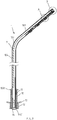
FIG. 1 is a structural schematic diagram of the present invention. -
FIG. 2 is an assembly view of the present invention. -
FIG. 3 is a section view of the present invention. -
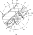
FIG. 4 is an enlarged view of the A region inFIG. 3 . -
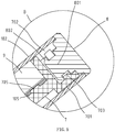
FIG. 5 is an enlarged view of the B region inFIG. 3 . -
FIG. 6 is a structural schematic diagram of the lamp holder. -
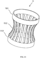
FIG. 7 is a structural schematic diagram of a lens. -
FIG. 8 is a structural schematic diagram of the cover cap. -
FIG. 9 is a structural schematic diagram of the mounting member. -
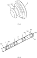
FIG. 10 is a combined view of the mounting member, the cover cap, the lamp holder and the lens. -
FIG. 11 is a cross-sectional view of a heat conduction strip. -
FIG. 12 is a structural schematic diagram of the limiting member. -
FIG. 13 is a structural schematic diagram of the elastic member. - Embodiments of the invention are described in detail below. Examples of the embodiments are shown in the appended drawings in which consistently identical or similar labels represent identical or similar elements or elements having the same or similar function. The embodiments described below by reference to the drawings are exemplary and are only used for the interpretation of the invention and cannot be understood to be a limitation of the invention.
- As shown in
FIG. 1 ,FIG. 2 andFIG. 3 , the lamp in the embodiment comprises anelongated housing 1 which is an elongated tubular member with a diameter of 0.5-1.5 cm. Thehousing 1 may be provided with abent part 103 which divides thehousing 1 into two parts, one of which is alamp pole part 104, and the other of which is alamp head part 102. When the lamp is used, thelamp pole part 104 is vertically arranged, and thelamp head part 102 is inclined. There are three light-emittingunits 101 on thelamp head part 102 and the light-emitting directions of the three light-emittingunits 101 evenly spaced along the length direction of thehousing 1 are inclined downward. The light emitted by the three light-emittingunits 101 can form a light spot to form a focused illumination for the area to be illuminated. Of course, the number of the light-emittingunits 101 can be set according to actual needs without limitation. - The structure of one of the light-emitting
units 101 will be described in the following. As shown inFIG. 4 ,FIG. 6, and FIG. 7 , each of the light-emittingunits 101 includes alight source 2 arranged in thelamp head part 102, afastening member 3 arranged inlamp head part 102, a mountinghole 4 arranged on the outer wall of thelamp head part 102, alens holder 5 arranged in the mountinghole 4 and fastened to thefastening member 3, and alens 6 arranged in thelens holder 5; - The
lens holder 5 is a sleeve-shaped member with two openings at both ends. The inner wall of thelens holder 5 may be provided with anannular card slot 502, thelens 6 may be provided with a secondannular flange 601, and the axis of the secondannular flange 601 may coincide with the optical axis of thelens 6. When thelens 6 is installed, thelens 6 is pressed into thelens holder 5, making the secondannular flange 601 to be fastened in theannular card slot 502 so as to make thelens 6 be fastened in thelens holder 5; - The
fastening member 3 may be provided with afastening hole 301. The inner wall of thefastening hole 301 may be symmetrically provided with two protruding buckles 302. The outer wall of thelens holder 5 may be provided with a firstannular flange 501. When thelens holder 5 is mounted, thelens holder 5 may be inserted into the mountinghole 4 and thefastening hole 301, and the firstannular flange 501 may be fastened to the two protrudingbuckles 302 to fix thelens holder 5; - The
light source 2 is an LED which is arranged on thecircuit board 105; - When the light-emitting unit is assembled, the
lens 6 is fastened and fixed into thelens holder 5, and then thelens holder 5 is inserted into the mountinghole 4, and thelens holder 5 is fastened and fixed in thefastening hole 301 of thefastening member 3, so that thelens holder 5 can be fixed. After thelens holder 5 is fixed, thelens holder 5 covers thelight source 2, so that the light emitted by thelight source 2 is graded through thelens 6 and then emitted; The above is the structure and assembly method of one of the light-emitting units, and the structure and assembly method of the other light-emitting units are consistent with that of this light-emitting unit. - As shown in
FIG. 2 ,FIG. 9 andFIG. 10 , thefastening members 3 of the three light-emittingunits 101 may be integrally arranged on a mountingmember 7 which is elongated, arranged in thehousing 1 and provided with two positioningposts 705. Thecircuit board 105 may be provided with two positioning holes, and thecircuit board 105 is fixed on the mountingmember 7. The twopositioning posts 705 on the mountingmember 7 may be respectively inserted and fixed in two positioning holes on the circuit board to make the relative position of thecircuit board 105 to the mountingmember 7 be fixed, that is, thepositioning post 705 positions thecircuit board 105 so that the threelight sources 2 on thecircuit board 105 are in the threefastening holes 301 on the mountingmember 7 respectively. - As shown in
FIG. 5 ,FIG. 8 ,FIG. 9 , andFIG. 10 , acover cap 8 may be arranged at one end of thehousing 1 adjacent to the light-emittingunit 101, and thecover cap 8 may be used to cover the end of thehousing 1. The mountingmember 7 may be connected with thecover cap 8, and the mountingmember 7 and thecover cap 8 may be fixed in the length direction of thehousing 1. In this way, after thecover cap 8 covers the end of thehousing 1, thecover cap 8 is fixed, so that thecover cap 8 also positions the mountingmember 7. After the mountingmember 7 is positioned, the threefastening holes 301 on the mountingmember 7 are respectively aligned with the three mountingholes 4 on thehousing 1, so that thelamp holder 5 can be mounted to the mountinghole 4 and fastened in thefastening hole 301. The mountingmember 7 is detachably connected to thecover cap 8. More specifically, a connectingpost 801 may be arranged on one surface of thecover cap 8 facing the mountingmember 7. The connectingpost 801 may be provided with a fourthannular flange 802. One end of the mountingmember 7 may be provided with atubular connecting part 701 with one end opened and the other end closed, and anotch 702 for connecting the connectingpost 801 to the connectingpart 701 may be arranged on the peripheral wall of the connectingpart 701. A thirdannular flange 703 may be arranged on the inner wall of the connectingpart 701, and the area between the thirdannular flange 703 on the connectingpart 701 and theclosed end 704 of the connectingpart 701 may be used to clamp the fourthannular flange 802 on the connectingpost 801. In this way, when thecover cap 8 is connected to the mountingmember 7, the fourthannular flange 802 on thecover cap 8 can be inserted into the area between the thirdannular flange 703 on the connectingpart 701 and the closed end of the connectingpart 701 through thenotch 702, so that the fourthannular flange 802 can be axially limited in the area between the thirdannular flange 703 of the connectingpart 701 and the closed end of the connectingpart 701 and thecover cap 8 and the mountingmember 7 can be axially limited. - As shown in
FIG. 3 andFIG. 11 , thehousing 1 may be provided with aheat conduction strip 9 made of materials that are easy to conduct heat and in contact with thecircuit board 105 in thehousing 1. The heat generated by the electronic components on thecircuit board 105 during operation is conducted to theheat conduction strip 9 which extends along the length direction of thehousing 1. Any cross section of theheat conduction strip 9 is provided with anarc part 901 which is in contact with the inner wall of thehousing 1, that is, the entireheat conduction strip 9 is in contact with the inner wall of thehousing 1. In this way, the heat on theheat conduction strip 9 can be evenly dispersed to all parts of thehousing 1 in contact with theheat conduction strip 9, so that the heat is relatively dispersed, the temperature on all parts of thehousing 1 is even, and there will be no too high local temperature onhousing 1. - As shown in
FIG. 3 , the lower end of thehousing 1 may be provided with a mounting mechanism for mounting the lamp, which comprises a mountingsleeve 10, anelastic member 11, anut 12, alower support plate 13 and a limitingmember 14; - The mounting
sleeve 10 is movably arranged in thehousing 1, making thehousing 1 axially movable along the mountingsleeve 10 which is fixed to the mounting station of the lamp. The outer wall of the mountingsleeve 10 may be provided with a thread, and the upper end of the mountingsleeve 10 may be provided with anupper support plate 1001 which extends radially outward and can be an annular structure or a plurality of separate support blocks as long as theupper support plate 1001 can support and fix the mountingsleeve 10 on a mounting surface; theelastic member 11 may be arranged in the mountingsleeve 10, and theelastic member 11 may be used to apply an elastic clamping force to thehousing 1, so that thehousing 1 can move relative to the mountingsleeve 10 when the axial force is applied to thehousing 1. However, theelastic member 11 can clamp and fixhousing 1 when the axial force is not applied to thehousing 1; thenut 12 is screwed on the mountingsleeve 10, and thenut 12 can move axially relative to the mountingsleeve 10 by rotating thenut 12; thelower support plate 13 is movably sleeved on the mountingsleeve 10, thelower support plate 13 is axially movable relative to the mountingsleeve 10, and thelower support plate 13 is located between thenut 12 and theupper support plate 1001, in this way, when rotating thenut 12, thenut 12 can push thelower support plate 13 to move toward theupper support plate 1001; the limitingmember 14 is inserted and fixed in thehousing 1, and the limitingmember 14 is axially limited with thehousing 1. The lower end of the limitingmember 14 is provided with a limitingpart 1401 for abutting against the lower end of the mountingsleeve 10. In this way, when the force applied to thehousing 1 cause thehousing 1 to move axially relative to the mountingsleeve 10, the limitingpart 1401 can limit the moving distance of thehousing 1. As shown inFIG.3 , at this time, the limitingpart 1401 abuts against the lower end of the mountingsleeve 10, making thehousing 1 unable to continue to move upward so as to prevent thehousing 1 from continuing to move upward but make it be removed from the mountingsleeve 10; - When the lamp of the embodiment is installed through the mounting mechanism, it should be mounted on a bottom plate where there should be a mounting hole. First, the mounting
sleeve 10 is inserted into the mounting hole of the bottom plate, so that theupper support plate 1001 on the mountingsleeve 10 abuts against the upper surface of the bottom plate, and then thelower support plate 13 is placed on the mountingsleeve 10, making thelower support plate 13 abut against the lower surface of the bottom plate, then thenut 12 is screwed onto the mounting sleeve to make thenut 12 press thelower support plate 13 against the lower surface of the bottom plate. In this way, thelower support plate 13 and theupper support plate 1001 clamp and fix the mountingsleeve 10 to the bottom plate, thehousing 1 is inserted from the upper end of the mountingsleeve 10 and through the mountingsleeve 10, and then the limitingmember 14 is inserted into the lower end of thehousing 1 for fixation. The wire in thehousing 1 can pass through the through hole in the limitingmember 14, thus completing the mounting of the lamp of this embodiment. - As shown in
FIG. 13 , theelastic member 11 comprises twoannular members 1101 which are coaxially arranged. A plurality ofelastic pieces 1102 are connected between the twoannular members 1101 and circumferentially spaced along theannular member 1101. Each of theelastic pieces 1102 is recessed toward the axial direction of theannular member 1101, so that when thehousing 1 is inserted into theelastic member 11, a plurality ofelastic pieces 1102 can apply an elastic clamping force to thehousing 1. - As shown in
FIG. 12 , the limitingmember 14 comprises two insertingparts 1402 axially inserted into the lower end of thehousing 1. The two insertingparts 1402 are in contact with the inner wall of thehousing 1, one of the inserting parts is provided with aprotrusion 1404 which is arranged on a surface of the insertingpart 1402 that is in contact with the inner wall of thehousing 1. The inner wall of thehousing 1 is provided with a corresponding groove. When the limitingmember 14 is inserted into thehousing 1, theprotrusion 1404 is inserted into the groove to make the limitingmember 14 and thehousing 1 axial limit, so that the limitingmember 14 is fixed with thehousing 1. There is a gap between the two insertingparts 1402 for the passage of the wires in thehousing 1. The opposite faces of the two insertingparts 1402 are provided with a plurality ofteeth 1403, and the wires in thehousing 1 are connected to thecircuit board 105 in the housing to provide power and control signals to thecircuit board 105. The limitingmember 14 is provided with a throughhole 1405, through which the wires in thehousing 1 can be extended. Theteeth 1403 on the two insertingparts 1402 are alternately arranged with each other and can clamp the wires through theteeth 1403 on the two insertingparts 1402 to avoid wire sloshing. - The above disclosure has been described by way of example and in terms of exemplary embodiment, and it is to be understood that the disclosure is not limited thereto.
Claims (10)
- A lamp with elongated housing (1), comprising:an elongated tubular housing (1);at least one light-emitting unit (101) arranged on the elongated tubular housing (1);each light-emitting unit (101) comprising:a light source (2) arranged in the elongated tubular housing (1);a fastening member (3) arranged in the elongated tubular housing (1);a mounting hole (4) arranged in the outer wall of the elongated tubular housing (1);a lens holder (5) arranged in the mounting hole (4) and fastened to the fastening member (3); anda lens (6) arranged in the lens holder (5);characterized in that the lens holder (5) is a sleeve-shaped member.
- The lamp with elongated housing (1) as claimed in claim 1, comprising a plurality of light-emitting units (101) which are spaced apart along the length direction of the elongated tubular housing (1).
- The lamp with elongated housing (1) as claimed in claim 2, wherein the elongated tubular housing
(1) is provided with a mounting member (7), and the fastening members (3) of the plurality of light-emitting units (101) are arranged on the mounting member (7). - The lamp with elongated housing (1) as claimed in claim 3, wherein one end of the elongated tubular housing (1) adjacent to the plurality of light-emitting units (101) is provided with a cover cap (8) for covering the end of the elongated tubular housing (1) the mounting member (7) is connected with the cover cap (8), and
the mounting member (7) and the cover cap (8) are mutually fixed in the length direction of the elongated tubular housing (1). - The lamp with elongated housing (1) as claimed in claim 4, wherein the mounting member (7) is detachably connected to the cover cap (8).
- The lamp with elongated housing (1) as claimed in claim 5, wherein
a connecting post (801) is arranged on one surface of the cover cap (8) facing the mounting member (7),
the connecting post (801) is provided with a fourth annular flange (802),
one end of the mounting member (7) is provided with a tubular connecting part (701) with one end opened and the other end closed,
a notch (702) for connecting the connecting post (801) to the tubular connecting part (701) is provided on the peripheral wall of the tubular connecting part (701), a third annular flange (703) is arranged on the inner wall of the tubular connecting part (701),
the area between the third annular flange (703) on the tubular connecting part (701) and the closed end of the tubular connecting part (701) is used to clamp the fourth annular flange (802) on the connecting post (801). - The lamp with elongated housing (1) as claimed in any of the preceding claims, wherein the lens (6) is fastened to the lens holder (5).
- The lamp with elongated housing as claimed in any of the preceding claims, wherein
the elongated tubular housing (1) is provided with a heat conduction strip (9) which contacts with a circuit board (105) in the elongated tubular housing (1) and extends along the length direction of the elongated tubular housing (1), and
an arc part (901) of the heat conduction strip (9) contacting the inner wall of the elongated tubular housing (1) is arranged on any cross section of the heat conduction strip (9). - The lamp with elongated housing (1) as claimed in any of the preceding claims, wherein the lower end of the elongated tubular housing (1) is provided with a mounting mechanism for
mounting the lamp, said mounting mechanism comprising:
a mounting sleeve (10) for fixing an installation position of the lamp, wherein the mounting sleeve (10) is movably sleeved on the elongated tubular housing (1) and the elongated tubular housing is axially movable along the mounting sleeve (10);
an elastic member (11) arranged in the mounting sleeve (10), for exerting an elastic clamping force on the elongated tubular housing (1); a limiting member (14) inserted and fixed to the lower end of the elongated tubular housing (1), wherein the limiting member (14) is axially limited with the elongated tubular housing (1) and the lower end of the limiting member (14) is provided with a limiting part (1401) for abutting against the lower end of the mounting sleeve (10). - The lamp with elongated housing (1) as claimed in claim 9, wherein the limiting member (14) comprises two inserting parts (1402) axially inserted into the lower end of the elongated tubular housing (1) and in contact with the inner wall of the elongated tubular housing (1), wherein one of the inserting parts (1402) is axially limited with the elongated tubular housing (1) a gap is provided between the two inserting parts (1402) for the passage of the wires in the elongated tubular housing (1), and the opposite faces of the two inserting parts (1402) are provided with a plurality of teeth (1403) for clamping the wires.
Applications Claiming Priority (1)
| Application Number | Priority Date | Filing Date | Title |
|---|---|---|---|
| CN201811012837.2A CN109084224B (en) | 2018-08-31 | 2018-08-31 | Lamp with slender shell |
Publications (2)
| Publication Number | Publication Date |
|---|---|
| EP3617583A1 EP3617583A1 (en) | 2020-03-04 |
| EP3617583B1 true EP3617583B1 (en) | 2021-05-12 |
Family
ID=64840293
Family Applications (1)
| Application Number | Title | Priority Date | Filing Date |
|---|---|---|---|
| EP19194659.9A Active EP3617583B1 (en) | 2018-08-31 | 2019-08-30 | Lamp with elongated housing |
Country Status (3)
| Country | Link |
|---|---|
| US (1) | US10969084B2 (en) |
| EP (1) | EP3617583B1 (en) |
| CN (1) | CN109084224B (en) |
Families Citing this family (4)
| Publication number | Priority date | Publication date | Assignee | Title |
|---|---|---|---|---|
| CN111140784A (en) * | 2019-11-30 | 2020-05-12 | 赛尔富电子有限公司 | Strip lamp of showcase |
| CN114966144B (en) * | 2022-07-22 | 2022-10-28 | 中科雷凌激光科技(山东)有限公司 | an adjustable probe |
| USD1051481S1 (en) * | 2022-09-22 | 2024-11-12 | Tangram Factory, Inc. | Lamp |
| USD1035087S1 (en) * | 2023-07-10 | 2024-07-09 | Lefei Du | Light |
Family Cites Families (29)
| Publication number | Priority date | Publication date | Assignee | Title |
|---|---|---|---|---|
| TW523237U (en) * | 2000-12-15 | 2003-03-01 | Senton Entpr Co Ltd | Notebook used lamp device |
| US20050007778A1 (en) * | 2003-07-08 | 2005-01-13 | Jack Lin | Lamp structure for an electrical device |
| US7066619B2 (en) * | 2003-08-29 | 2006-06-27 | Waters Michael A | LED picture light apparatus and method |
| US7409147B2 (en) * | 2004-01-30 | 2008-08-05 | Samsung Techwin Co., Ltd. | Video presenter with arch-type support |
| US20060072327A1 (en) * | 2004-09-30 | 2006-04-06 | Adesso Inc. | Gooseneck lighting apparatus with decorative jelly sleeve |
| US7703966B2 (en) * | 2005-03-11 | 2010-04-27 | Panther Vision, Llc | Work light |
| US7306349B2 (en) * | 2005-03-11 | 2007-12-11 | Michael Waters | Work light |
| US7699492B2 (en) * | 2006-12-08 | 2010-04-20 | Levine Jonathan E | Lighting device with clip |
| US7798684B2 (en) * | 2007-04-06 | 2010-09-21 | Genlyte Thomas Group Llc | Luminaire system with thermal chimney effect |
| US7591572B1 (en) * | 2007-04-11 | 2009-09-22 | Levine Jonathan E | Compact lighting device |
| NL2000996C2 (en) * | 2007-11-12 | 2008-09-15 | Ind Tech Verlichting B V | LED light fixture for e.g. street lighting, has LED's protected from weather by refractive optical components |
| TW201000819A (en) * | 2008-06-30 | 2010-01-01 | Create Electronic Optical Co Ltd | LED illumination device |
| JP4447644B2 (en) * | 2008-07-15 | 2010-04-07 | シーシーエス株式会社 | Light irradiation device |
| CN101994946B (en) * | 2009-08-27 | 2015-06-17 | 鸿富锦精密工业(深圳)有限公司 | Rotary desk lamp and rotating and positioning mechanism thereof |
| US9016895B2 (en) * | 2011-03-30 | 2015-04-28 | Innovative Lighting, Inc. | LED lighting fixture with reconfigurable light distribution pattern |
| KR20120131713A (en) * | 2011-05-26 | 2012-12-05 | 삼성전자주식회사 | Variable light apparutus |
| KR101309698B1 (en) * | 2011-12-29 | 2013-09-17 | 정상민 | Lighting Apparatus |
| DE202012012811U1 (en) * | 2012-12-06 | 2014-01-30 | Nils vom Brocke | Retractable desk lamp |
| CN203771335U (en) * | 2014-03-17 | 2014-08-13 | 宁波唯嘉电子科技有限公司 | Telescopic working lamp |
| CN103994350B (en) * | 2014-05-09 | 2015-11-25 | 东莞嘉盛照明科技有限公司 | LED lamp |
| US20150362148A1 (en) * | 2014-06-11 | 2015-12-17 | Brightline, Inc. | Personal Video Conference Lighting Assembly |
| WO2017082582A1 (en) * | 2015-11-12 | 2017-05-18 | 전기호 | Led lamp |
| CN105927894A (en) * | 2016-06-22 | 2016-09-07 | 广东百事泰电子商务股份有限公司 | Detachable multipurpose table lamp |
| WO2018058648A1 (en) * | 2016-09-30 | 2018-04-05 | 深圳市柔宇科技有限公司 | Illumination device |
| WO2018058641A1 (en) * | 2016-09-30 | 2018-04-05 | 深圳市柔宇科技有限公司 | Lamp rod rotating assembly and illumination device |
| WO2018058653A1 (en) * | 2016-09-30 | 2018-04-05 | 深圳市柔宇科技有限公司 | Illumination device |
| DE102016225199A1 (en) * | 2016-12-15 | 2018-06-21 | H4X E.U. | lighting system |
| CN206739061U (en) * | 2017-04-25 | 2017-12-12 | 宁波升谱光电股份有限公司 | Lamp casing structure and the cabinet lamp with the lamp casing structure |
| CN208804530U (en) * | 2018-08-31 | 2019-04-30 | 赛尔富电子有限公司 | Luminaire with elongated housing |
-
2018
- 2018-08-31 CN CN201811012837.2A patent/CN109084224B/en active Active
-
2019
- 2019-08-28 US US16/554,320 patent/US10969084B2/en active Active
- 2019-08-30 EP EP19194659.9A patent/EP3617583B1/en active Active
Non-Patent Citations (1)
| Title |
|---|
| None * |
Also Published As
| Publication number | Publication date |
|---|---|
| US20200072443A1 (en) | 2020-03-05 |
| CN109084224A (en) | 2018-12-25 |
| EP3617583A1 (en) | 2020-03-04 |
| US10969084B2 (en) | 2021-04-06 |
| CN109084224B (en) | 2024-08-13 |
Similar Documents
| Publication | Publication Date | Title |
|---|---|---|
| US10969084B2 (en) | Lamp with elongated housing | |
| US11028987B2 (en) | Double-row matrix illumination module and auxiliary illumination method thereof | |
| US7226190B2 (en) | Portable lighting device with light-emitting diode | |
| US7178937B2 (en) | Lighting device and method for lighting | |
| US8939618B2 (en) | Light flux controlling member, light emitting apparatus, and illumination apparatus | |
| KR101405868B1 (en) | Method for producing a laser device | |
| WO2020250758A1 (en) | Optical unit and vehicle lamp | |
| EP3199861A1 (en) | Led lamp and led light source module thereof | |
| JP2020095965A (en) | Lighting equipment | |
| DE102013006995A1 (en) | Ring illumination device for a microscope objective and microscope objective | |
| JP5276286B2 (en) | Optical device | |
| EP3959468B1 (en) | Holding collimator elements in a lighting arrangement | |
| US11947145B2 (en) | Stage light fixture with split light mixing device | |
| JP6955116B2 (en) | Electrical devices for vehicle running boards | |
| US6082884A (en) | Adjustable fiber optic lighting fixture for individually adjusting the color, focal length and aim of the produced light and method | |
| KR101603867B1 (en) | High-intensity lighting equipment for flat panel display inspection | |
| CN110764336B (en) | Pocket flash lamp | |
| CN208804530U (en) | Luminaire with elongated housing | |
| EP3854176B1 (en) | Heating zone with an illumination device for a cooking hob | |
| KR101104855B1 (en) | Beam adjustable wall light | |
| KR102317896B1 (en) | LED Lamp Apparatus | |
| JP7045352B2 (en) | lighting equipment | |
| EP4036466A1 (en) | Assembly of light module, lens and reflector with double bayonet fastening, method of assembly of assembly and use | |
| JP7798575B2 (en) | Illumination unit for microscopes | |
| JP6785617B2 (en) | Vehicle lighting |
Legal Events
| Date | Code | Title | Description |
|---|---|---|---|
| PUAI | Public reference made under article 153(3) epc to a published international application that has entered the european phase |
Free format text: ORIGINAL CODE: 0009012 |
|
| STAA | Information on the status of an ep patent application or granted ep patent |
Free format text: STATUS: THE APPLICATION HAS BEEN PUBLISHED |
|
| AK | Designated contracting states |
Kind code of ref document: A1 Designated state(s): AL AT BE BG CH CY CZ DE DK EE ES FI FR GB GR HR HU IE IS IT LI LT LU LV MC MK MT NL NO PL PT RO RS SE SI SK SM TR |
|
| AX | Request for extension of the european patent |
Extension state: BA ME |
|
| STAA | Information on the status of an ep patent application or granted ep patent |
Free format text: STATUS: REQUEST FOR EXAMINATION WAS MADE |
|
| 17P | Request for examination filed |
Effective date: 20200807 |
|
| RBV | Designated contracting states (corrected) |
Designated state(s): AL AT BE BG CH CY CZ DE DK EE ES FI FR GB GR HR HU IE IS IT LI LT LU LV MC MK MT NL NO PL PT RO RS SE SI SK SM TR |
|
| RIC1 | Information provided on ipc code assigned before grant |
Ipc: F21V 5/04 20060101ALI20200911BHEP Ipc: F21V 19/00 20060101ALI20200911BHEP Ipc: F21Y 115/10 20160101ALN20200911BHEP Ipc: F21Y 103/10 20160101ALN20200911BHEP Ipc: F21V 21/04 20060101ALI20200911BHEP Ipc: F21S 8/08 20060101AFI20200911BHEP Ipc: F21V 17/16 20060101ALN20200911BHEP Ipc: F21V 15/01 20060101ALI20200911BHEP Ipc: F21V 17/00 20060101ALN20200911BHEP |
|
| RIC1 | Information provided on ipc code assigned before grant |
Ipc: F21S 8/08 20060101AFI20201102BHEP Ipc: F21V 15/01 20060101ALI20201102BHEP Ipc: F21V 17/00 20060101ALN20201102BHEP Ipc: F21V 17/16 20060101ALN20201102BHEP Ipc: F21V 5/04 20060101ALI20201102BHEP Ipc: F21V 19/00 20060101ALI20201102BHEP Ipc: F21Y 103/10 20160101ALN20201102BHEP Ipc: F21Y 115/10 20160101ALN20201102BHEP Ipc: F21V 21/04 20060101ALI20201102BHEP |
|
| GRAP | Despatch of communication of intention to grant a patent |
Free format text: ORIGINAL CODE: EPIDOSNIGR1 |
|
| STAA | Information on the status of an ep patent application or granted ep patent |
Free format text: STATUS: GRANT OF PATENT IS INTENDED |
|
| INTG | Intention to grant announced |
Effective date: 20201215 |
|
| RAP1 | Party data changed (applicant data changed or rights of an application transferred) |
Owner name: SELF ELECTRONICS GERMANY GMBH Owner name: SELF ELECTRONICS CO., LTD. Owner name: LIN, WANJIONG |
|
| GRAS | Grant fee paid |
Free format text: ORIGINAL CODE: EPIDOSNIGR3 |
|
| GRAA | (expected) grant |
Free format text: ORIGINAL CODE: 0009210 |
|
| STAA | Information on the status of an ep patent application or granted ep patent |
Free format text: STATUS: THE PATENT HAS BEEN GRANTED |
|
| AK | Designated contracting states |
Kind code of ref document: B1 Designated state(s): AL AT BE BG CH CY CZ DE DK EE ES FI FR GB GR HR HU IE IS IT LI LT LU LV MC MK MT NL NO PL PT RO RS SE SI SK SM TR |
|
| REG | Reference to a national code |
Ref country code: GB Ref legal event code: FG4D |
|
| REG | Reference to a national code |
Ref country code: CH Ref legal event code: EP |
|
| REG | Reference to a national code |
Ref country code: DE Ref legal event code: R096 Ref document number: 602019004572 Country of ref document: DE |
|
| REG | Reference to a national code |
Ref country code: IE Ref legal event code: FG4D |
|
| REG | Reference to a national code |
Ref country code: AT Ref legal event code: REF Ref document number: 1392409 Country of ref document: AT Kind code of ref document: T Effective date: 20210615 |
|
| REG | Reference to a national code |
Ref country code: LT Ref legal event code: MG9D |
|
| REG | Reference to a national code |
Ref country code: AT Ref legal event code: MK05 Ref document number: 1392409 Country of ref document: AT Kind code of ref document: T Effective date: 20210512 |
|
| REG | Reference to a national code |
Ref country code: NL Ref legal event code: MP Effective date: 20210512 |
|
| PG25 | Lapsed in a contracting state [announced via postgrant information from national office to epo] |
Ref country code: FI Free format text: LAPSE BECAUSE OF FAILURE TO SUBMIT A TRANSLATION OF THE DESCRIPTION OR TO PAY THE FEE WITHIN THE PRESCRIBED TIME-LIMIT Effective date: 20210512 Ref country code: HR Free format text: LAPSE BECAUSE OF FAILURE TO SUBMIT A TRANSLATION OF THE DESCRIPTION OR TO PAY THE FEE WITHIN THE PRESCRIBED TIME-LIMIT Effective date: 20210512 Ref country code: LT Free format text: LAPSE BECAUSE OF FAILURE TO SUBMIT A TRANSLATION OF THE DESCRIPTION OR TO PAY THE FEE WITHIN THE PRESCRIBED TIME-LIMIT Effective date: 20210512 Ref country code: AT Free format text: LAPSE BECAUSE OF FAILURE TO SUBMIT A TRANSLATION OF THE DESCRIPTION OR TO PAY THE FEE WITHIN THE PRESCRIBED TIME-LIMIT Effective date: 20210512 Ref country code: BG Free format text: LAPSE BECAUSE OF FAILURE TO SUBMIT A TRANSLATION OF THE DESCRIPTION OR TO PAY THE FEE WITHIN THE PRESCRIBED TIME-LIMIT Effective date: 20210812 |
|
| PG25 | Lapsed in a contracting state [announced via postgrant information from national office to epo] |
Ref country code: LV Free format text: LAPSE BECAUSE OF FAILURE TO SUBMIT A TRANSLATION OF THE DESCRIPTION OR TO PAY THE FEE WITHIN THE PRESCRIBED TIME-LIMIT Effective date: 20210512 Ref country code: NO Free format text: LAPSE BECAUSE OF FAILURE TO SUBMIT A TRANSLATION OF THE DESCRIPTION OR TO PAY THE FEE WITHIN THE PRESCRIBED TIME-LIMIT Effective date: 20210812 Ref country code: PL Free format text: LAPSE BECAUSE OF FAILURE TO SUBMIT A TRANSLATION OF THE DESCRIPTION OR TO PAY THE FEE WITHIN THE PRESCRIBED TIME-LIMIT Effective date: 20210512 Ref country code: RS Free format text: LAPSE BECAUSE OF FAILURE TO SUBMIT A TRANSLATION OF THE DESCRIPTION OR TO PAY THE FEE WITHIN THE PRESCRIBED TIME-LIMIT Effective date: 20210512 Ref country code: PT Free format text: LAPSE BECAUSE OF FAILURE TO SUBMIT A TRANSLATION OF THE DESCRIPTION OR TO PAY THE FEE WITHIN THE PRESCRIBED TIME-LIMIT Effective date: 20210913 Ref country code: SE Free format text: LAPSE BECAUSE OF FAILURE TO SUBMIT A TRANSLATION OF THE DESCRIPTION OR TO PAY THE FEE WITHIN THE PRESCRIBED TIME-LIMIT Effective date: 20210512 Ref country code: GR Free format text: LAPSE BECAUSE OF FAILURE TO SUBMIT A TRANSLATION OF THE DESCRIPTION OR TO PAY THE FEE WITHIN THE PRESCRIBED TIME-LIMIT Effective date: 20210813 Ref country code: IS Free format text: LAPSE BECAUSE OF FAILURE TO SUBMIT A TRANSLATION OF THE DESCRIPTION OR TO PAY THE FEE WITHIN THE PRESCRIBED TIME-LIMIT Effective date: 20210912 |
|
| PG25 | Lapsed in a contracting state [announced via postgrant information from national office to epo] |
Ref country code: NL Free format text: LAPSE BECAUSE OF FAILURE TO SUBMIT A TRANSLATION OF THE DESCRIPTION OR TO PAY THE FEE WITHIN THE PRESCRIBED TIME-LIMIT Effective date: 20210512 |
|
| PG25 | Lapsed in a contracting state [announced via postgrant information from national office to epo] |
Ref country code: SK Free format text: LAPSE BECAUSE OF FAILURE TO SUBMIT A TRANSLATION OF THE DESCRIPTION OR TO PAY THE FEE WITHIN THE PRESCRIBED TIME-LIMIT Effective date: 20210512 Ref country code: ES Free format text: LAPSE BECAUSE OF FAILURE TO SUBMIT A TRANSLATION OF THE DESCRIPTION OR TO PAY THE FEE WITHIN THE PRESCRIBED TIME-LIMIT Effective date: 20210512 Ref country code: EE Free format text: LAPSE BECAUSE OF FAILURE TO SUBMIT A TRANSLATION OF THE DESCRIPTION OR TO PAY THE FEE WITHIN THE PRESCRIBED TIME-LIMIT Effective date: 20210512 Ref country code: DK Free format text: LAPSE BECAUSE OF FAILURE TO SUBMIT A TRANSLATION OF THE DESCRIPTION OR TO PAY THE FEE WITHIN THE PRESCRIBED TIME-LIMIT Effective date: 20210512 Ref country code: CZ Free format text: LAPSE BECAUSE OF FAILURE TO SUBMIT A TRANSLATION OF THE DESCRIPTION OR TO PAY THE FEE WITHIN THE PRESCRIBED TIME-LIMIT Effective date: 20210512 Ref country code: RO Free format text: LAPSE BECAUSE OF FAILURE TO SUBMIT A TRANSLATION OF THE DESCRIPTION OR TO PAY THE FEE WITHIN THE PRESCRIBED TIME-LIMIT Effective date: 20210512 Ref country code: SM Free format text: LAPSE BECAUSE OF FAILURE TO SUBMIT A TRANSLATION OF THE DESCRIPTION OR TO PAY THE FEE WITHIN THE PRESCRIBED TIME-LIMIT Effective date: 20210512 |
|
| REG | Reference to a national code |
Ref country code: DE Ref legal event code: R097 Ref document number: 602019004572 Country of ref document: DE |
|
| PLBE | No opposition filed within time limit |
Free format text: ORIGINAL CODE: 0009261 |
|
| STAA | Information on the status of an ep patent application or granted ep patent |
Free format text: STATUS: NO OPPOSITION FILED WITHIN TIME LIMIT |
|
| PG25 | Lapsed in a contracting state [announced via postgrant information from national office to epo] |
Ref country code: MC Free format text: LAPSE BECAUSE OF FAILURE TO SUBMIT A TRANSLATION OF THE DESCRIPTION OR TO PAY THE FEE WITHIN THE PRESCRIBED TIME-LIMIT Effective date: 20210512 |
|
| 26N | No opposition filed |
Effective date: 20220215 |
|
| REG | Reference to a national code |
Ref country code: BE Ref legal event code: MM Effective date: 20210831 |
|
| PG25 | Lapsed in a contracting state [announced via postgrant information from national office to epo] |
Ref country code: IS Free format text: LAPSE BECAUSE OF FAILURE TO SUBMIT A TRANSLATION OF THE DESCRIPTION OR TO PAY THE FEE WITHIN THE PRESCRIBED TIME-LIMIT Effective date: 20210912 Ref country code: LU Free format text: LAPSE BECAUSE OF NON-PAYMENT OF DUE FEES Effective date: 20210830 Ref country code: AL Free format text: LAPSE BECAUSE OF FAILURE TO SUBMIT A TRANSLATION OF THE DESCRIPTION OR TO PAY THE FEE WITHIN THE PRESCRIBED TIME-LIMIT Effective date: 20210512 |
|
| PG25 | Lapsed in a contracting state [announced via postgrant information from national office to epo] |
Ref country code: IE Free format text: LAPSE BECAUSE OF NON-PAYMENT OF DUE FEES Effective date: 20210830 Ref country code: BE Free format text: LAPSE BECAUSE OF NON-PAYMENT OF DUE FEES Effective date: 20210831 |
|
| PG25 | Lapsed in a contracting state [announced via postgrant information from national office to epo] |
Ref country code: CY Free format text: LAPSE BECAUSE OF FAILURE TO SUBMIT A TRANSLATION OF THE DESCRIPTION OR TO PAY THE FEE WITHIN THE PRESCRIBED TIME-LIMIT Effective date: 20210512 |
|
| PG25 | Lapsed in a contracting state [announced via postgrant information from national office to epo] |
Ref country code: HU Free format text: LAPSE BECAUSE OF FAILURE TO SUBMIT A TRANSLATION OF THE DESCRIPTION OR TO PAY THE FEE WITHIN THE PRESCRIBED TIME-LIMIT; INVALID AB INITIO Effective date: 20190830 |
|
| GBPC | Gb: european patent ceased through non-payment of renewal fee |
Effective date: 20230830 |
|
| PG25 | Lapsed in a contracting state [announced via postgrant information from national office to epo] |
Ref country code: MK Free format text: LAPSE BECAUSE OF FAILURE TO SUBMIT A TRANSLATION OF THE DESCRIPTION OR TO PAY THE FEE WITHIN THE PRESCRIBED TIME-LIMIT Effective date: 20210512 |
|
| PG25 | Lapsed in a contracting state [announced via postgrant information from national office to epo] |
Ref country code: GB Free format text: LAPSE BECAUSE OF NON-PAYMENT OF DUE FEES Effective date: 20230830 |
|
| PG25 | Lapsed in a contracting state [announced via postgrant information from national office to epo] |
Ref country code: GB Free format text: LAPSE BECAUSE OF NON-PAYMENT OF DUE FEES Effective date: 20230830 |
|
| PG25 | Lapsed in a contracting state [announced via postgrant information from national office to epo] |
Ref country code: MT Free format text: LAPSE BECAUSE OF FAILURE TO SUBMIT A TRANSLATION OF THE DESCRIPTION OR TO PAY THE FEE WITHIN THE PRESCRIBED TIME-LIMIT Effective date: 20210512 |
|
| PGFP | Annual fee paid to national office [announced via postgrant information from national office to epo] |
Ref country code: DE Payment date: 20250829 Year of fee payment: 7 |
|
| PGFP | Annual fee paid to national office [announced via postgrant information from national office to epo] |
Ref country code: IT Payment date: 20250829 Year of fee payment: 7 |
|
| PGFP | Annual fee paid to national office [announced via postgrant information from national office to epo] |
Ref country code: FR Payment date: 20250829 Year of fee payment: 7 |
|
| PGFP | Annual fee paid to national office [announced via postgrant information from national office to epo] |
Ref country code: CH Payment date: 20250901 Year of fee payment: 7 |
|
| PG25 | Lapsed in a contracting state [announced via postgrant information from national office to epo] |
Ref country code: TR Free format text: LAPSE BECAUSE OF FAILURE TO SUBMIT A TRANSLATION OF THE DESCRIPTION OR TO PAY THE FEE WITHIN THE PRESCRIBED TIME-LIMIT Effective date: 20210512 |