EP3617558B1 - Gearshift lever device - Google Patents
Gearshift lever device Download PDFInfo
- Publication number
- EP3617558B1 EP3617558B1 EP19193954.5A EP19193954A EP3617558B1 EP 3617558 B1 EP3617558 B1 EP 3617558B1 EP 19193954 A EP19193954 A EP 19193954A EP 3617558 B1 EP3617558 B1 EP 3617558B1
- Authority
- EP
- European Patent Office
- Prior art keywords
- gearshift lever
- gearshift
- moved
- lever
- lock
- Prior art date
- Legal status (The legal status is an assumption and is not a legal conclusion. Google has not performed a legal analysis and makes no representation as to the accuracy of the status listed.)
- Active
Links
Images


Classifications
-
- B—PERFORMING OPERATIONS; TRANSPORTING
- B60—VEHICLES IN GENERAL
- B60K—ARRANGEMENT OR MOUNTING OF PROPULSION UNITS OR OF TRANSMISSIONS IN VEHICLES; ARRANGEMENT OR MOUNTING OF PLURAL DIVERSE PRIME-MOVERS IN VEHICLES; AUXILIARY DRIVES FOR VEHICLES; INSTRUMENTATION OR DASHBOARDS FOR VEHICLES; ARRANGEMENTS IN CONNECTION WITH COOLING, AIR INTAKE, GAS EXHAUST OR FUEL SUPPLY OF PROPULSION UNITS IN VEHICLES
- B60K20/00—Arrangement or mounting of change-speed gearing control devices in vehicles
- B60K20/02—Arrangement or mounting of change-speed gearing control devices in vehicles of initiating means
-
- F—MECHANICAL ENGINEERING; LIGHTING; HEATING; WEAPONS; BLASTING
- F16—ENGINEERING ELEMENTS AND UNITS; GENERAL MEASURES FOR PRODUCING AND MAINTAINING EFFECTIVE FUNCTIONING OF MACHINES OR INSTALLATIONS; THERMAL INSULATION IN GENERAL
- F16H—GEARING
- F16H59/00—Control inputs to control units of change-speed- or reversing-gearings for conveying rotary motion
- F16H59/02—Selector apparatus
- F16H59/0204—Selector apparatus for automatic transmissions with means for range selection and manual shifting, e.g. range selector with tiptronic
-
- F—MECHANICAL ENGINEERING; LIGHTING; HEATING; WEAPONS; BLASTING
- F16—ENGINEERING ELEMENTS AND UNITS; GENERAL MEASURES FOR PRODUCING AND MAINTAINING EFFECTIVE FUNCTIONING OF MACHINES OR INSTALLATIONS; THERMAL INSULATION IN GENERAL
- F16H—GEARING
- F16H59/00—Control inputs to control units of change-speed- or reversing-gearings for conveying rotary motion
- F16H59/02—Selector apparatus
- F16H59/0278—Constructional features of the selector lever, e.g. grip parts, mounting or manufacturing
-
- F—MECHANICAL ENGINEERING; LIGHTING; HEATING; WEAPONS; BLASTING
- F16—ENGINEERING ELEMENTS AND UNITS; GENERAL MEASURES FOR PRODUCING AND MAINTAINING EFFECTIVE FUNCTIONING OF MACHINES OR INSTALLATIONS; THERMAL INSULATION IN GENERAL
- F16H—GEARING
- F16H59/00—Control inputs to control units of change-speed- or reversing-gearings for conveying rotary motion
- F16H59/02—Selector apparatus
- F16H59/04—Ratio selector apparatus
-
- F—MECHANICAL ENGINEERING; LIGHTING; HEATING; WEAPONS; BLASTING
- F16—ENGINEERING ELEMENTS AND UNITS; GENERAL MEASURES FOR PRODUCING AND MAINTAINING EFFECTIVE FUNCTIONING OF MACHINES OR INSTALLATIONS; THERMAL INSULATION IN GENERAL
- F16H—GEARING
- F16H59/00—Control inputs to control units of change-speed- or reversing-gearings for conveying rotary motion
- F16H59/02—Selector apparatus
- F16H59/08—Range selector apparatus
- F16H59/10—Range selector apparatus comprising levers
-
- F—MECHANICAL ENGINEERING; LIGHTING; HEATING; WEAPONS; BLASTING
- F16—ENGINEERING ELEMENTS AND UNITS; GENERAL MEASURES FOR PRODUCING AND MAINTAINING EFFECTIVE FUNCTIONING OF MACHINES OR INSTALLATIONS; THERMAL INSULATION IN GENERAL
- F16H—GEARING
- F16H59/00—Control inputs to control units of change-speed- or reversing-gearings for conveying rotary motion
- F16H59/02—Selector apparatus
- F16H2059/026—Details or special features of the selector casing or lever support
Definitions
- the present invention relates to a gearshift lever device of an automatic transmission.
- the gearshift lever device of Japanese Patent Application Publication No. H9-263151 uses a joint to allow a gearshift lever to be moved in a front-rear direction (shift direction) in the auto mode and the manual mode and to be moved in a right-left direction (select direction) for switching between the auto mode and the manual mode.
- the joint includes a first tube body along the right-left direction (select direction) and a second tube body along the front-rear direction (shift direction).
- the gearshift lever is moved in the front-rear direction (shift direction) about an axial center of the first tube body and is moved in the right-left direction (select direction) about an axial center of the second tube body.
- a compression rod inserted in the tubular gearshift lever is pushed upward by a spring.
- the spring is supported with its lower end engaged with a protrusion portion formed on an upper surface of the second tube body. With an operation button formed at an upper portion of the gearshift lever pressed, the compression rod is moved downward against the spring to enable operations of the gearshift lever in the auto mode.
- a gearshift lever device according to the preamble of independent claim 1 is disclosed in Japanese Patent Application Publication No. 2005-119440 .
- the object of the present invention is to implement a configuration for moving a gearshift lever in a right-left direction and a front-rear direction by moving the gearshift lever about a spherical portion on a lower portion of the gearshift lever, which is also capable of supporting a lower end of an elastic body pushing a compression rod upward
- a gearshift lever device according to the present invention is defined in independent claim 1. Preferred embodiments are set out in the dependent claims.
- a gearshift lever device allows a gearshift lever to be operated in both an auto mode and a manual mode.
- the gearshift lever device includes a gearshift lever, a spherical portion that is formed in a lower portion of the gearshift lever and supports the gearshift lever while allowing the gearshift lever to be moved in a front-rear direction in the auto mode or the manual mode and supports the gearshift lever while allowing the gearshift lever to be moved in a right-left direction to switch between the auto mode or the manual mode; a compression rod that is arranged in the gearshift lever movably in a vehicle top-down direction and that, when an operation portion formed on the gearshift lever is operated in the auto mode, is moved downward in the gearshift lever to enable operations of the gearshift lever in the front-rear direction; an elastic body that is arranged at a lower portion in the gearshift lever and pushes the compression rod upward; and a support member that is attached to the gearshift lever and supports a lower portion of the elastic body.
- the support member includes an
- a gearshift lever device of an aspect of the present invention it is possible to implement a configuration for moving a gearshift lever about a spherical portion on a lower portion of the gearshift lever to move the gearshift lever in a right-left direction and a front-rear direction, which still can support a lower end of an elastic body pushing a compression rod.
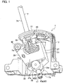
- Fig. 1 illustrates an internal configuration of a gearshift lever device 1 used in a vehicle (an automobile).
- "front-rear direction” and “right-left direction” respectively correspond to a front-rear direction and a right-left direction of the vehicle in which the gearshift lever device 1 is mounted.
- an arrow X indicates the right-left direction (select direction)
- an arrow Y indicates the front-rear direction (shift direction)
- an arrow Z indicates a top-down direction (vehicle top-down direction).
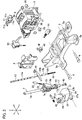
- a housing 3 is assembled on a base 5 illustrated in Fig. 2 with fix pins 6.
- the base 5 is fixed on an unillustrated vehicle body using mounting portions 5a.
- a lower portion of a gearshift lever 7 is inserted to the housing 3.
- a cover 8 is put on one opening in the right-left direction X of the housing 3.
- an upper surface portion 9 of the housing 3 has a curved concave shape, which is an arc shape in the front-rear direction Y.
- a cover panel 11 is put on the upper surface portion 9.
- An auto mode shift path 11a for automatic transmission operation and a manual mode shift path 11b for manual transmission operation are formed on the cover panel 11.
- AD (drive) range of the auto mode shift path 11a and a neutral position of the manual mode shift path 11b are connected through a select operation shift path 11c.
- the auto mode shift path 11a is long in the front-rear direction Y, and the manual mode shift path 11b is positioned around a rear portion of the auto mode shift path 11a and has a shorter length in the front-rear direction Y than the auto mode shift path 11a.
- An opening 9a corresponding to the auto mode shift path 11a, the manual mode shift path 11b, and the select operation shift path 11c is formed in the upper surface portion 9 of the housing 3.
- the gearshift lever 7 includes a lever main body 7A, which is a cylinder and is hollow along the entire length in an axial direction, and a resin molded body 7B, which is molded of resin integrally on a lower outer circumference of the lever main body 7A.
- a compression rod 13 is inserted in the lever main body 7A movably in the axial direction.
- a cylindrical portion 17 is formed on a lower end portion, and a spherical portion 19 is formed next to an upper portion of the cylindrical portion 17.
- a tube portion 21 is obliquely formed on a side portion above the spherical portion 19.
- a check spring 23 and a check pin 25 that is pushed in an upward projecting direction by the check spring 23 are housed in the tube portion 21.
- the check pin 25 is engaged with an unillustrated check groove formed in the housing 3.
- the resin molded body 7B is supported by a select block 27.
- the select block 27 includes a front wall portion 29, a rear wall portion 31, and a bottom wall portion 33.
- a spherical reception portion 35 that receives the spherical portion 19 is formed on the bottom wall portion 33.
- a cylindrical portion 17 is inserted to penetrate through a through hole 35a formed in the spherical reception portion 35.
- the through hole 35a is formed to be greater than an outer diameter of the cylindrical portion 17 so as to allow the cylindrical portion 17 to move in the right-left direction when the gearshift lever 7 is moved in the select operation shift path 11c in the right-left direction.
- a lower end of the lever main body 7A reaches a center position of the spherical portion 19.
- a cylindrical space in the cylindrical portion 17 of the resin molded body 7B is continuously formed in the spherical portion 19, and the space is continued to the internal space of the lever main body 7A.
- Shaft portions 37a, 37b extending in the right-left direction X are formed in right and left sides of the spherical reception portion 35.
- the shaft portions 37a, 37b are rotatably supported by a shaft hole 39 of the housing 3 with bushes 36. This allows the select block 27 to be shifted in the front-rear direction Y about the shaft portions 37a, 37b.
- the gearshift lever 7 is moved in the right-left direction (select direction) X about the spherical portion 19.
- the gearshift lever 7 is moved from the auto mode shift path 11a in the left direction to the manual mode shift path 11b, the fitting of the resin molded body 7B and the select block 27 is released.
- the gearshift lever 7 is moved from the manual mode shift path 11b in the right direction to the auto mode shift path 11a, the resin molded body 7B is fitted to the select block 27.
- the fitting of the resin molded body 7B and the select block 27 is made by inserting an upper portion of the resin molded body 7B to a space between the front wall portion 29 and the rear wall portion 31 of the select block 27.
- the compression rod 13 is divided into a rod upper portion 13a and a rod lower portion 13b that is shorter than the rod upper portion 13a, and a position pin 45 extending in the right-left direction X is arranged between the rod upper portion 13a and the rod lower portion 13b.
- the position pin 45 includes insertion protrusions 45a, 45b formed on the top and the bottom of its middle part in the right-left direction, and the insertion protrusions 45a, 45b are respectively inserted to insides of the rod upper portion 13a and the rod lower portion 13b.
- a through hole 7a that is long in the top-down direction Z is formed in a part corresponding to the resin molded body 7B of the gearshift lever 7.
- the through hole 7a penetrates the lever main body 7A and the resin molded body 7B at a position above the spherical portion 19.
- the position pin 45 is inserted to the through hole 7a movably in the top-down direction Z.
- the position pin 45 projects outside the resin molded body 7B from the through hole 7a, and the projecting parts around tip ends are inserted to a position gate 47 of the housing 3.
- the position pin 45 is moved inside the position gate 47 by operation of the gearshift lever 7.
- a coil spring 41 as an elastic body is housed below the rod lower portion 13b of the compression rod 13.
- the coil spring 41 pushes the compression rod 13 upward.
- a protrusion 13b1 projecting downward from a lower end of the rod lower portion 13b is inserted to an upper portion of the coil spring 41.
- a stopper 43 as a support member attached on a lower end of the gearshift lever 7 prevents the coil spring 41 from falling out.
- the stopper 43 includes a substantially ring shaped base portion 43a.
- the base portion 43a includes a pair of arc portions 43a1 opposed to each other and a pair of rectangular portions 43a2 opposed to each other in positions spaced 90 degrees apart in a circumferential direction from the positions of the arc portions 43a1.
- a pair of leg portions 43b are formed to stand upright from inner circumferential sides of the corresponding arc portions 43a1.
- an upper end surface of the base portion 43a is in contact with a lower end of the cylindrical portion 17 of the resin molded body 7B.
- a total outer diameter of the pair of arc portions 43a1 is substantially equal to an outer diameter of the cylindrical portion 17, a substantially entire area of top surfaces of the arc portions 43a1 is in contact with a lower end surface of the cylindrical portion 17.
- the pair of leg portions 43b are positioned to oppose to each other.
- Each leg portion 43b forms a part (substantially 1/4) of a cylindrical member in a circumferential direction. Consequently, openings 43c are respectively formed between each of the pair of leg portions 43b in the circumferential direction.
- a flat plate portion 43d As illustrated in Fig. 5C , the flat plate portion 43d is substantially oval in plan view. A protrusion portion 43e projecting upward is formed on a top surface of the flat plate portion 43d. A cross section of the protrusion portion 43e is circle, and a diameter of the circle of the protrusion portion 43e in a tip end side (upper end side) is smaller than that in a base end side (lower end side).
- Each lock portion 43f includes an arm portion 43fl including an upper portion connected to the flat plate portion 43d and a tab portion 43f2 formed on a lower portion of the arm portions 43fl.
- the arm portion 43f1 is long in the top-down direction Z and is elastically deformed such that the tab portion 43f2 on the lower portion is moved between inside and outside of the opening 43c while being supported at the upper portion.
- the tab portions 43f2 are positioned above the base portion 43a and are away from the base portion 43a.
- Lock holes 17a into which the tab portions 43f2 enter are formed in the cylindrical portion 17 of the resin molded body 7B.
- the tab portions 43f2 enter the lock holes 17a, and the tab portions 43f2 prevent the stopper 43 from falling out from the cylindrical portion 17.
- outer circumferential surfaces of the leg portions 43b are substantially in contact with an inner circumferential surface of the cylindrical portion 17.
- tip ends of the tab portions 43f2 press the inner circumferential surface of the cylindrical portion 17, and thus the pair of arm portions 43f1 are elastically deformed in a direction in which they come close to each other. Thereafter, once the tab portions 43f2 are locked in the lock holes 17a, the pair of arm portions 43f1 is restored from the elastically deformed state to the original form.
- the stopper 43 While the stopper 43 is attached on the cylindrical portion 17, the protrusion portion 43e is inserted in the coil spring 41 as illustrated in Fig. 3 . In this state, a lower end of the coil spring 41 is in contact with the top surface of the flat plate portion 43d. In other words, the flat plate portion 43d serves as a spring receiver of the coil spring 41.
- each tab portion 43f2 includes an upper inclined surface 43f3, an outer circumferential cylindrical surface 43f4, and a lower end surface 43f5.
- the upper inclined surface 43f3 is inclined such that a lower end is positioned farther to the outside from a central axis in the top-down direction Z than an upper end.
- an upper end is continued to the upper inclined surface 43f3, and a lower end is continued to the lower end surface 43f5.
- the lower end surface 43f5 is inclined such that an outer circumference side end portion is located below an inner circumference side end portion. Since the lower end surface 43f5 is inclined, tip end sides of the tab portions 43f2 are elastically deformed upward easily when the stopper 43 is pushed downward by the coil spring 41 and the tab portions 43f2 are pressed on edges of the lock holes 17a.
- Fig. 2 illustrates constituents such as a shift-lock lever 49, a solenoid 51 that releases the shift-lock lever 49, and a forcible release lever 53 that releases shift-lock by forcibly turning the shift-lock lever 49.
- the shift-lock lever 49 is for preventing the gearshift lever 7 from moving from a parking position when parking the vehicle.
- the solenoid 51 is activated when a brake pedal is stepped down at the start-up of an engine and the gearshift lever 7 is in a P (parking) range of the auto mode shift path 11a, and then the shift-lock of the shift-lock lever 49 is released.
- the operation button on the upper portion of the gearshift lever 7 is pressed in this state, the compression rod 13 is moved downward with the position pin 45. This allows the position pin 45 to move rearward in the position gate 47 and allows the gearshift lever 7 to be moved in the front-rear direction in the auto mode shift path 11a. While the compression rod 13 is moving downward, the coil spring 41 is compressed. Once stopping the operation of pressing the operation button, the compression rod 13 is pushed by the coil spring 41 and moved upward.
- the gearshift lever device 1 of this embodiment allows the gearshift lever 7 to be operated in both the auto mode and manual mode.
- the gearshift lever device 1 includes the spherical portion 19 that is formed in the lower portion of the gearshift lever 7 and supports the gearshift lever 7 while allowing the gearshift lever 7 to be moved in the front-rear direction Y in the auto mode or the manual mode and supports the gearshift lever 7 while allowing the gearshift lever 7 to be moved in the right-left direction X to switch between the auto mode or the manual mode.
- the gearshift lever device 1 includes the compression rod 13 that is arranged in the gearshift lever 7 movably in the axial direction and that, when the operation button as the operation portion formed on the gearshift lever 7 is operated in the auto mode, is moved downward in the gearshift lever 7 to enable operations of the gearshift lever 7 in the front-rear direction Y.
- the gearshift lever device 1 includes the coil spring 41 that is arranged at the lower portion in the gearshift lever 7 and pushes the compression rod 13 upward and the stopper 43 that is attached to the gearshift lever 7 and supports the lower portion of the coil spring 41.
- the stopper 43 includes insertion portions (leg portions 43b, protrusion portions 43e) that are inserted from the opening at the lower end of the gearshift lever 7 and the lock portions 43f that are locked in the lock holes 17a in the gearshift lever 7 with the insertion portions inserted in the gearshift lever 7.
- the configuration for moving the gearshift lever 7 in the right-left direction (select direction) X and the front-rear direction (shift direction) Y is implemented by moving the gearshift lever 7 about the spherical portion 19 formed in the lower portion of the gearshift lever 7.
- the stopper 43 Even in such a gearshift lever device 1, the lower end of the coil spring 41 pushing the compression rod 13 upward can be supported by the stopper 43.
- the insertion portions, or specifically the leg portions 43b are inserted in the gearshift lever 7, and the outer circumferential surfaces of the leg portions 43b are substantially in contact with the inner circumferential surface of the gearshift lever 7 (cylindrical portion 17); thus, the parts are assembled in a stable manner.
- the elastic body pushing the compression rod 13 upward is formed of the coil spring 41, and the protrusion portion 43e on the tip end side of the lock portion 43f is inserted in the coil spring 41.
- the protrusion portion 43e can suppress the deformation of the coil spring 41 curved in a direction crossing the compression or extension direction.
- the lock portions 43f of this embodiment include the tab portions 43f2, a trailing end side of the tab portion in the insertion direction of the insertion portions being pressed on the edges of the lock holes 17a while the tab portions 43f2 are locked in the lock holes 17a.
- the lower end surface 43f5 of each tab portion 43f2, which is a portion opposed to the edge, is inclined such that the tip end side of the tab portion 43f2 is positioned behind the base end side of the tab portion 43f2 in the right-left direction of the vehicle (X).
- the tip end sides of the tab portions 43f2 are easily elastically deformed upward when the stopper 43 is pushed downward by the coil spring 41 and the lower end surfaces 43f5 are pressed on the edges of the lock holes 17a.
- the upward elastic deformation of the tab portions 43f2 makes it possible to suppress a backlash generated when the stopper 43 is attached on the cylindrical portion 17, and thus the parts can be assembled in the stable manner.
- the coil spring 41 is used as the elastic body that pushes the compression rod 13 upward.
- the compression rod 13 can be moved downward by a predetermined amount when the operation button is pressed, it is not limited to the coil spring 41.
- the protrusion portions 43e are not necessarily required as long as the configuration allows the lower end of the coil spring 41 to be in contact with the flat plate portion 43d.
Landscapes
- Engineering & Computer Science (AREA)
- General Engineering & Computer Science (AREA)
- Mechanical Engineering (AREA)
- Chemical & Material Sciences (AREA)
- Combustion & Propulsion (AREA)
- Transportation (AREA)
- Arrangement Or Mounting Of Control Devices For Change-Speed Gearing (AREA)
Description
- The present invention relates to a gearshift lever device of an automatic transmission.
- There has been known an automatic transmission of an automobile including a gearshift lever device that allows a driver to switch the driving mode to a manual mode while keeping a D (drive) range in an auto mode and to manually perform shift-up and shift-down (see Japanese Patent Application Publication No.
H9-263151 H9-263151 - The gearshift lever is moved in the front-rear direction (shift direction) about an axial center of the first tube body and is moved in the right-left direction (select direction) about an axial center of the second tube body. A compression rod inserted in the tubular gearshift lever is pushed upward by a spring. The spring is supported with its lower end engaged with a protrusion portion formed on an upper surface of the second tube body. With an operation button formed at an upper portion of the gearshift lever pressed, the compression rod is moved downward against the spring to enable operations of the gearshift lever in the auto mode. A gearshift lever device according to the preamble of independent claim 1 is disclosed in Japanese Patent Application Publication No.
2005-119440 - As a configuration for moving the gearshift lever in the right-left direction and the front-rear direction, there is one that allows the gearshift lever to be moved about a spherical portion formed on a lower portion of the gearshift lever without using the joint including the first and second tube bodies. In this case, since the spherical portion is formed integrally with the gearshift lever, it is difficult to employ the configuration of Japanese Patent Application Publication No.
H9-263151 - In view of this, the object of the present invention is to implement a configuration for moving a gearshift lever in a right-left direction and a front-rear direction by moving the gearshift lever about a spherical portion on a lower portion of the gearshift lever, which is also capable of supporting a lower end of an elastic body pushing a compression rod upward A gearshift lever device according to the present invention is defined in independent claim 1. Preferred embodiments are set out in the dependent claims.
- A gearshift lever device according to an aspect of the present invention allows a gearshift lever to be operated in both an auto mode and a manual mode. The gearshift lever device includes a gearshift lever, a spherical portion that is formed in a lower portion of the gearshift lever and supports the gearshift lever while allowing the gearshift lever to be moved in a front-rear direction in the auto mode or the manual mode and supports the gearshift lever while allowing the gearshift lever to be moved in a right-left direction to switch between the auto mode or the manual mode; a compression rod that is arranged in the gearshift lever movably in a vehicle top-down direction and that, when an operation portion formed on the gearshift lever is operated in the auto mode, is moved downward in the gearshift lever to enable operations of the gearshift lever in the front-rear direction; an elastic body that is arranged at a lower portion in the gearshift lever and pushes the compression rod upward; and a support member that is attached to the gearshift lever and supports a lower portion of the elastic body. The support member includes an insertion portion that is to be inserted from an opening in a lower end of the gearshift lever and a lock portion that is to be locked in a lock hole in the gearshift lever with the insertion portion inserted in the gearshift lever.
- According to a gearshift lever device of an aspect of the present invention, it is possible to implement a configuration for moving a gearshift lever about a spherical portion on a lower portion of the gearshift lever to move the gearshift lever in a right-left direction and a front-rear direction, which still can support a lower end of an elastic body pushing a compression rod.
-
-
Fig. 1 is a perspective view that illustrates inside of a housing of a gearshift lever device according to an embodiment of the present invention. -
Fig. 2 is an exploded perspective view of the gearshift lever device inFig. 1 . -
Fig. 3 is a cross-sectional view taken along a position of an axial center of a gearshift lever in the gearshift lever device inFig. 1 . -
Fig. 4 is a perspective view of a stopper attached on a lower end opening of the gearshift lever in the gearshift lever device inFig. 1 . -
Fig. 5A is a front view of the stopper inFig. 4 . -
Fig. 5B is a side view ofFig. 5A . -
Fig. 5C is a plan view ofFig. 5B . -
Fig. 5D is a cross-sectional view taken along the A-A line inFig. 5B . - An embodiment of the present invention is described below in detail with reference to the drawings.
-
Fig. 1 illustrates an internal configuration of a gearshift lever device 1 used in a vehicle (an automobile). In the following descriptions, "front-rear direction" and "right-left direction" respectively correspond to a front-rear direction and a right-left direction of the vehicle in which the gearshift lever device 1 is mounted. InFig. 2 , an arrow X indicates the right-left direction (select direction), an arrow Y indicates the front-rear direction (shift direction), and an arrow Z indicates a top-down direction (vehicle top-down direction). In the gearshift lever device 1, a housing 3 is assembled on a base 5 illustrated inFig. 2 withfix pins 6. The base 5 is fixed on an unillustrated vehicle body using mountingportions 5a. A lower portion of agearshift lever 7 is inserted to the housing 3. Acover 8 is put on one opening in the right-left direction X of the housing 3. - As illustrated in
Fig. 2 , anupper surface portion 9 of the housing 3 has a curved concave shape, which is an arc shape in the front-rear direction Y. Acover panel 11 is put on theupper surface portion 9. An automode shift path 11a for automatic transmission operation and a manualmode shift path 11b for manual transmission operation are formed on thecover panel 11. AD (drive) range of the automode shift path 11a and a neutral position of the manualmode shift path 11b are connected through a selectoperation shift path 11c. - The auto
mode shift path 11a is long in the front-rear direction Y, and the manualmode shift path 11b is positioned around a rear portion of the automode shift path 11a and has a shorter length in the front-rear direction Y than the automode shift path 11a. An opening 9a corresponding to the automode shift path 11a, the manualmode shift path 11b, and the selectoperation shift path 11c is formed in theupper surface portion 9 of the housing 3. - The
gearshift lever 7 includes a levermain body 7A, which is a cylinder and is hollow along the entire length in an axial direction, and a resin moldedbody 7B, which is molded of resin integrally on a lower outer circumference of the levermain body 7A. Acompression rod 13 is inserted in the levermain body 7A movably in the axial direction. In the resin moldedbody 7B, acylindrical portion 17 is formed on a lower end portion, and aspherical portion 19 is formed next to an upper portion of thecylindrical portion 17. - In the resin molded
body 7B, atube portion 21 is obliquely formed on a side portion above thespherical portion 19. Acheck spring 23 and acheck pin 25 that is pushed in an upward projecting direction by thecheck spring 23 are housed in thetube portion 21. Thecheck pin 25 is engaged with an unillustrated check groove formed in the housing 3. - The resin molded
body 7B is supported by aselect block 27. Theselect block 27 includes afront wall portion 29, arear wall portion 31, and abottom wall portion 33. As illustrated inFig. 3 , aspherical reception portion 35 that receives thespherical portion 19 is formed on thebottom wall portion 33. Acylindrical portion 17 is inserted to penetrate through a throughhole 35a formed in thespherical reception portion 35. The throughhole 35a is formed to be greater than an outer diameter of thecylindrical portion 17 so as to allow thecylindrical portion 17 to move in the right-left direction when thegearshift lever 7 is moved in the selectoperation shift path 11c in the right-left direction. - A lower end of the lever
main body 7A reaches a center position of thespherical portion 19. A cylindrical space in thecylindrical portion 17 of the resin moldedbody 7B is continuously formed in thespherical portion 19, and the space is continued to the internal space of the levermain body 7A. With thespherical portion 19 sliding and rotating in the front-rear and right-left directions relative to thespherical reception portion 35, thegearshift lever 7 is moved in the front-rear direction (shift direction) Y and the right-left direction (select direction) X. -
Shaft portions spherical reception portion 35. As illustrated inFig. 3 , in theselect block 27, theshaft portions shaft hole 39 of the housing 3 withbushes 36. This allows theselect block 27 to be shifted in the front-rear direction Y about theshaft portions - As described above, the
gearshift lever 7 is moved in the right-left direction (select direction) X about thespherical portion 19. When thegearshift lever 7 is moved from the automode shift path 11a in the left direction to the manualmode shift path 11b, the fitting of the resin moldedbody 7B and theselect block 27 is released. On the other hand, when thegearshift lever 7 is moved from the manualmode shift path 11b in the right direction to the automode shift path 11a, the resin moldedbody 7B is fitted to theselect block 27. The fitting of the resin moldedbody 7B and theselect block 27 is made by inserting an upper portion of the resin moldedbody 7B to a space between thefront wall portion 29 and therear wall portion 31 of theselect block 27. - With the
gearshift lever 7 moved in the front-rear direction while the resin moldedbody 7B is fitted to theselect block 27, theselect block 27 is moved together in the front-rear direction about theshaft portions front wall portion 29 of theselect block 27, acable coupling portion 40 to which one end of an unillustrated cable is to be coupled using acable pin 38 is formed. The other end of the cable is coupled to an unillustrated automatic transmission. - An unillustrated operation nob is formed on an upper portion of the
gearshift lever 7, and thecompression rod 13 is moved downward by pressing an operation button formed on the operation knob. Thecompression rod 13 is divided into a rodupper portion 13a and a rodlower portion 13b that is shorter than the rodupper portion 13a, and aposition pin 45 extending in the right-left direction X is arranged between the rodupper portion 13a and the rodlower portion 13b. Theposition pin 45 includesinsertion protrusions insertion protrusions upper portion 13a and the rodlower portion 13b. - A through
hole 7a that is long in the top-down direction Z is formed in a part corresponding to the resin moldedbody 7B of thegearshift lever 7. The throughhole 7a penetrates the levermain body 7A and the resin moldedbody 7B at a position above thespherical portion 19. Theposition pin 45 is inserted to the throughhole 7a movably in the top-down direction Z. Theposition pin 45 projects outside the resin moldedbody 7B from the throughhole 7a, and the projecting parts around tip ends are inserted to aposition gate 47 of the housing 3. Theposition pin 45 is moved inside theposition gate 47 by operation of thegearshift lever 7. - In the
gearshift lever 7, acoil spring 41 as an elastic body is housed below the rodlower portion 13b of thecompression rod 13. Thecoil spring 41 pushes thecompression rod 13 upward. During the pushing, a protrusion 13b1 projecting downward from a lower end of the rodlower portion 13b is inserted to an upper portion of thecoil spring 41. Astopper 43 as a support member attached on a lower end of thegearshift lever 7 prevents thecoil spring 41 from falling out. - As illustrated in
Figs. 4 and5A to5D , thestopper 43 includes a substantially ring shapedbase portion 43a. Thebase portion 43a includes a pair of arc portions 43a1 opposed to each other and a pair of rectangular portions 43a2 opposed to each other in positions spaced 90 degrees apart in a circumferential direction from the positions of the arc portions 43a1. A pair ofleg portions 43b are formed to stand upright from inner circumferential sides of the corresponding arc portions 43a1. - As illustrated in
Figs. 1 and3 , an upper end surface of thebase portion 43a is in contact with a lower end of thecylindrical portion 17 of the resin moldedbody 7B. Specifically, since a total outer diameter of the pair of arc portions 43a1 is substantially equal to an outer diameter of thecylindrical portion 17, a substantially entire area of top surfaces of the arc portions 43a1 is in contact with a lower end surface of thecylindrical portion 17. The pair ofleg portions 43b are positioned to oppose to each other. Eachleg portion 43b forms a part (substantially 1/4) of a cylindrical member in a circumferential direction. Consequently,openings 43c are respectively formed between each of the pair ofleg portions 43b in the circumferential direction. - Upper ends of the pair of
leg portions 43b are connected by aflat plate portion 43d. As illustrated inFig. 5C , theflat plate portion 43d is substantially oval in plan view. Aprotrusion portion 43e projecting upward is formed on a top surface of theflat plate portion 43d. A cross section of theprotrusion portion 43e is circle, and a diameter of the circle of theprotrusion portion 43e in a tip end side (upper end side) is smaller than that in a base end side (lower end side). - In the
stopper 43, a pair oflock portions 43f are formed in theopenings 43c between the pair ofleg portions 43b. Eachlock portion 43f includes an arm portion 43fl including an upper portion connected to theflat plate portion 43d and a tab portion 43f2 formed on a lower portion of the arm portions 43fl. The arm portion 43f1 is long in the top-down direction Z and is elastically deformed such that the tab portion 43f2 on the lower portion is moved between inside and outside of theopening 43c while being supported at the upper portion. The tab portions 43f2 are positioned above thebase portion 43a and are away from thebase portion 43a. - Lock holes 17a into which the tab portions 43f2 enter are formed in the
cylindrical portion 17 of the resin moldedbody 7B. Thus, with thestopper 43 attached on thecylindrical portion 17 as illustrated inFig. 1 , the tab portions 43f2 enter thelock holes 17a, and the tab portions 43f2 prevent thestopper 43 from falling out from thecylindrical portion 17. At that time, outer circumferential surfaces of theleg portions 43b are substantially in contact with an inner circumferential surface of thecylindrical portion 17. - When the
stopper 43 is inserted to thecylindrical portion 17, tip ends of the tab portions 43f2 press the inner circumferential surface of thecylindrical portion 17, and thus the pair of arm portions 43f1 are elastically deformed in a direction in which they come close to each other. Thereafter, once the tab portions 43f2 are locked in thelock holes 17a, the pair of arm portions 43f1 is restored from the elastically deformed state to the original form. - While the
stopper 43 is attached on thecylindrical portion 17, theprotrusion portion 43e is inserted in thecoil spring 41 as illustrated inFig. 3 . In this state, a lower end of thecoil spring 41 is in contact with the top surface of theflat plate portion 43d. In other words, theflat plate portion 43d serves as a spring receiver of thecoil spring 41. - As illustrated in
Fig. 5D , each tab portion 43f2 includes an upper inclined surface 43f3, an outer circumferential cylindrical surface 43f4, and a lower end surface 43f5. The upper inclined surface 43f3 is inclined such that a lower end is positioned farther to the outside from a central axis in the top-down direction Z than an upper end. In the outer circumferential cylindrical surface 43f4, an upper end is continued to the upper inclined surface 43f3, and a lower end is continued to the lower end surface 43f5. The lower end surface 43f5 is inclined such that an outer circumference side end portion is located below an inner circumference side end portion. Since the lower end surface 43f5 is inclined, tip end sides of the tab portions 43f2 are elastically deformed upward easily when thestopper 43 is pushed downward by thecoil spring 41 and the tab portions 43f2 are pressed on edges of thelock holes 17a. -
Fig. 2 illustrates constituents such as a shift-lock lever 49, asolenoid 51 that releases the shift-lock lever 49, and aforcible release lever 53 that releases shift-lock by forcibly turning the shift-lock lever 49. The shift-lock lever 49 is for preventing thegearshift lever 7 from moving from a parking position when parking the vehicle. - Next, operations of the gearshift lever device 1 are described.
- The
solenoid 51 is activated when a brake pedal is stepped down at the start-up of an engine and thegearshift lever 7 is in a P (parking) range of the automode shift path 11a, and then the shift-lock of the shift-lock lever 49 is released. When the operation button on the upper portion of thegearshift lever 7 is pressed in this state, thecompression rod 13 is moved downward with theposition pin 45. This allows theposition pin 45 to move rearward in theposition gate 47 and allows thegearshift lever 7 to be moved in the front-rear direction in the automode shift path 11a. While thecompression rod 13 is moving downward, thecoil spring 41 is compressed. Once stopping the operation of pressing the operation button, thecompression rod 13 is pushed by thecoil spring 41 and moved upward. - With the
gearshift lever 7 moved in the front-rear direction in the automode shift path 11a, it is possible to select each of ranges in the auto mode. When thegearshift lever 7 in the D (drive) mode of the automode shift path 11a is moved to the manualmode shift path 11b by way of the selectoperation shift path 11c, the driving mode is shifted to the manual mode. In the manual mode, it is possible to manually perform shift-up and shift-down by moving thegearshift lever 7 in the front-rear direction. - When the
gearshift lever 7 is moved in the front-rear direction in the automode shift path 11a, thegearshift lever 7 is shifted in the front-rear direction about theshaft portions select block 27. When thegearshift lever 7 is moved in the front-rear direction in the manualmode shift path 11b and moved in the right-left direction in the selectoperation shift path 11c, thespherical portion 19 slides and rotates relative to thespherical reception portion 35 of theselect block 27. - Next, operations and effects are described.
- The gearshift lever device 1 of this embodiment allows the
gearshift lever 7 to be operated in both the auto mode and manual mode. The gearshift lever device 1 includes thespherical portion 19 that is formed in the lower portion of thegearshift lever 7 and supports thegearshift lever 7 while allowing thegearshift lever 7 to be moved in the front-rear direction Y in the auto mode or the manual mode and supports thegearshift lever 7 while allowing thegearshift lever 7 to be moved in the right-left direction X to switch between the auto mode or the manual mode. The gearshift lever device 1 includes thecompression rod 13 that is arranged in thegearshift lever 7 movably in the axial direction and that, when the operation button as the operation portion formed on thegearshift lever 7 is operated in the auto mode, is moved downward in thegearshift lever 7 to enable operations of thegearshift lever 7 in the front-rear direction Y. - The gearshift lever device 1 includes the
coil spring 41 that is arranged at the lower portion in thegearshift lever 7 and pushes thecompression rod 13 upward and thestopper 43 that is attached to thegearshift lever 7 and supports the lower portion of thecoil spring 41. Thestopper 43 includes insertion portions (leg portions 43b,protrusion portions 43e) that are inserted from the opening at the lower end of thegearshift lever 7 and thelock portions 43f that are locked in thelock holes 17a in thegearshift lever 7 with the insertion portions inserted in thegearshift lever 7. - In the case of this embodiment, the configuration for moving the
gearshift lever 7 in the right-left direction (select direction) X and the front-rear direction (shift direction) Y is implemented by moving thegearshift lever 7 about thespherical portion 19 formed in the lower portion of thegearshift lever 7. Even in such a gearshift lever device 1, the lower end of thecoil spring 41 pushing thecompression rod 13 upward can be supported by thestopper 43. In this state, in thestopper 43, the insertion portions, or specifically theleg portions 43b, are inserted in thegearshift lever 7, and the outer circumferential surfaces of theleg portions 43b are substantially in contact with the inner circumferential surface of the gearshift lever 7 (cylindrical portion 17); thus, the parts are assembled in a stable manner. - In this embodiment, the elastic body pushing the
compression rod 13 upward is formed of thecoil spring 41, and theprotrusion portion 43e on the tip end side of thelock portion 43f is inserted in thecoil spring 41. In this case, when thecoil spring 41 is compressed or extended, theprotrusion portion 43e can suppress the deformation of thecoil spring 41 curved in a direction crossing the compression or extension direction. - The
lock portions 43f of this embodiment include the tab portions 43f2, a trailing end side of the tab portion in the insertion direction of the insertion portions being pressed on the edges of thelock holes 17a while the tab portions 43f2 are locked in thelock holes 17a. The lower end surface 43f5 of each tab portion 43f2, which is a portion opposed to the edge, is inclined such that the tip end side of the tab portion 43f2 is positioned behind the base end side of the tab portion 43f2 in the right-left direction of the vehicle (X). - Consequently, the tip end sides of the tab portions 43f2 are easily elastically deformed upward when the
stopper 43 is pushed downward by thecoil spring 41 and the lower end surfaces 43f5 are pressed on the edges of thelock holes 17a. The upward elastic deformation of the tab portions 43f2 makes it possible to suppress a backlash generated when thestopper 43 is attached on thecylindrical portion 17, and thus the parts can be assembled in the stable manner. - Although the embodiment of the present invention is described as above, the embodiment is merely an example described for facilitating understanding of the present invention, and the present invention is not limited to the embodiment. The technical scope of the present invention is defined in the claims.
- For example, in the above-described embodiment, the
coil spring 41 is used as the elastic body that pushes thecompression rod 13 upward. However, as long as thecompression rod 13 can be moved downward by a predetermined amount when the operation button is pressed, it is not limited to thecoil spring 41. Theprotrusion portions 43e are not necessarily required as long as the configuration allows the lower end of thecoil spring 41 to be in contact with theflat plate portion 43d.
Claims (3)
- A gearshift lever device (1) that allows a gearshift lever (7) to be operated in both an auto mode and a manual mode, comprising: the gearshift lever (7); a spherical portion (19) that is formed in a lower portion of the gearshift lever (7) and supports the gearshift lever (7) while allowing the gearshift lever (7) to be moved in a front-rear direction in the auto mode or the manual mode and supports the gearshift lever (7) while allowing the gearshift lever (7) to be moved in a right-left direction to switch between the auto mode or the manual mode;
a compression rod (13) that is arranged in the gearshift lever (7) movably in a vehicle top-down direction and that, when an operation portion formed on the gearshift lever (7) is operated in the auto mode, is moved downward in the gearshift lever (7) to enable operations of the gearshift lever (7) in the front-rear direction;
an elastic body that is arranged at a lower portion in the gearshift lever (7) and pushes the compression rod (13) upward; and
a support member (43) that is attached to the gearshift lever (7) and supports a lower portion of the elastic body, wherein
the support member (43) includes an insertion portion (43b, 43e) that is inserted from an opening at a
lower end of the gearshift lever (7),
characterized in that
the support member (43) further includes a lock portion (43f) that is locked in a lock hole (17a)
in the gearshift lever (7) with the insertion portion (43b, 43e) inserted in the gearshift lever (7) - The gearshift lever device (1) according to claim 1, wherein
the elastic body is formed of a coil spring (41), and the insertion portion located above the lock portion (43f) is inserted in the coil spring (41). - The gearshift lever device (1) according to claim 2, wherein
the lock portion (43f) includes a tab portion (43f2), a trailing end side of the tab portion (43f2) in the insertion direction of the insertion portions being pressed on an edge of the lock hole (17a) while the tab portion (43f2) is locked in the lock hole (17a), the lower end surface (43f5) of the tab portion (43f2), which is a portion opposed to the edge of the lock hole (17a), is inclined such that a tip end side of the tab portion (43f2) is positioned behind a base end side of the tab portion (43f2) in the right-left direction of the vehicle (X).
Applications Claiming Priority (1)
| Application Number | Priority Date | Filing Date | Title |
|---|---|---|---|
| JP2018162600A JP2020032926A (en) | 2018-08-31 | 2018-08-31 | Shift lever device |
Publications (2)
| Publication Number | Publication Date |
|---|---|
| EP3617558A1 EP3617558A1 (en) | 2020-03-04 |
| EP3617558B1 true EP3617558B1 (en) | 2021-05-12 |
Family
ID=67777115
Family Applications (1)
| Application Number | Title | Priority Date | Filing Date |
|---|---|---|---|
| EP19193954.5A Active EP3617558B1 (en) | 2018-08-31 | 2019-08-28 | Gearshift lever device |
Country Status (4)
| Country | Link |
|---|---|
| US (1) | US20200072342A1 (en) |
| EP (1) | EP3617558B1 (en) |
| JP (1) | JP2020032926A (en) |
| CN (1) | CN110871681A (en) |
Families Citing this family (1)
| Publication number | Priority date | Publication date | Assignee | Title |
|---|---|---|---|---|
| KR20210044341A (en) * | 2019-10-14 | 2021-04-23 | 현대자동차주식회사 | Shift lever assembly for vehicle |
Family Cites Families (10)
| Publication number | Priority date | Publication date | Assignee | Title |
|---|---|---|---|---|
| JP3352318B2 (en) | 1996-03-27 | 2002-12-03 | 富士機工株式会社 | Shifting device for automatic transmission of automobile |
| DE19844278C1 (en) * | 1998-09-26 | 2000-01-05 | Porsche Ag | Thrust block for actuating element spring support in gear lever blocking arrangement |
| JP4388342B2 (en) * | 2003-10-16 | 2009-12-24 | 本田技研工業株式会社 | Shift lever device for automatic transmission |
| JP5086130B2 (en) * | 2008-02-28 | 2012-11-28 | デルタ工業株式会社 | Shift device for automobile transmission |
| JP5225937B2 (en) * | 2009-06-08 | 2013-07-03 | デルタ工業株式会社 | Automatic transmission shift device |
| CN203189700U (en) * | 2013-03-26 | 2013-09-11 | 安徽江淮汽车股份有限公司 | Shift bar assembly and automatic transmission gear-shifting control mechanism |
| JP2015006866A (en) * | 2013-06-26 | 2015-01-15 | デルタ工業株式会社 | Automatic transmission shift device |
| JP6144722B2 (en) * | 2015-06-01 | 2017-06-07 | トヨタ自動車株式会社 | Vehicle shift device |
| JP2017081332A (en) * | 2015-10-27 | 2017-05-18 | 富士機工株式会社 | Shift lever device |
| CN205780804U (en) * | 2016-05-23 | 2016-12-07 | 宁波贝尔达汽车控制系统有限公司 | The automatic gear-box operating mechanism that suppression card is effective |
-
2018
- 2018-08-31 JP JP2018162600A patent/JP2020032926A/en active Pending
-
2019
- 2019-08-21 US US16/546,383 patent/US20200072342A1/en not_active Abandoned
- 2019-08-28 EP EP19193954.5A patent/EP3617558B1/en active Active
- 2019-08-30 CN CN201910817413.1A patent/CN110871681A/en not_active Withdrawn
Non-Patent Citations (1)
| Title |
|---|
| None * |
Also Published As
| Publication number | Publication date |
|---|---|
| CN110871681A (en) | 2020-03-10 |
| US20200072342A1 (en) | 2020-03-05 |
| EP3617558A1 (en) | 2020-03-04 |
| JP2020032926A (en) | 2020-03-05 |
Similar Documents
| Publication | Publication Date | Title |
|---|---|---|
| US6230579B1 (en) | Multi-mode shifter assembly joint | |
| US7900534B2 (en) | Shifter for vehicle transmission | |
| US9032829B2 (en) | Button structure of shift knob | |
| US5372051A (en) | Shift lever assembly for power transmission of automotive vehicle | |
| US8375821B2 (en) | Actuating device | |
| EP0978669A2 (en) | Shift lever unit for dual-mode automatic transmission | |
| US6301994B1 (en) | Shift lever apparatus | |
| US20080098844A1 (en) | Shift lever device | |
| EP3617558B1 (en) | Gearshift lever device | |
| EP3306143B1 (en) | Gear shift device for motor vehicles | |
| KR100721890B1 (en) | Shift lever device | |
| US20080184837A1 (en) | Shift lever apparatus for automatic transmission | |
| US5575175A (en) | Shift lever assembly | |
| EP3617561A1 (en) | Gearshift lever device | |
| EP2009327B1 (en) | Shift lever apparatus for vehicle | |
| EP2009326B1 (en) | Shift lever apparatus for vehicle | |
| JPS6234324Y2 (en) | ||
| US20050217404A1 (en) | Selector apparatus of an automatic transmission of vehicle | |
| CN103522897B (en) | Vehicle-use transmission bar device | |
| JP6653975B2 (en) | AT shift lever device | |
| EP3617560B1 (en) | Gearshift lever device | |
| CN117249237A (en) | gear shifter | |
| CN110439995B (en) | Automatic gear shifter, limiting plate thereof and vehicle | |
| KR20250074589A (en) | Shifting device and vehicle equipped with the same | |
| JP2006248479A (en) | Shift lever device for automatic transmission |
Legal Events
| Date | Code | Title | Description |
|---|---|---|---|
| PUAI | Public reference made under article 153(3) epc to a published international application that has entered the european phase |
Free format text: ORIGINAL CODE: 0009012 |
|
| STAA | Information on the status of an ep patent application or granted ep patent |
Free format text: STATUS: THE APPLICATION HAS BEEN PUBLISHED |
|
| AK | Designated contracting states |
Kind code of ref document: A1 Designated state(s): AL AT BE BG CH CY CZ DE DK EE ES FI FR GB GR HR HU IE IS IT LI LT LU LV MC MK MT NL NO PL PT RO RS SE SI SK SM TR |
|
| AX | Request for extension of the european patent |
Extension state: BA ME |
|
| STAA | Information on the status of an ep patent application or granted ep patent |
Free format text: STATUS: REQUEST FOR EXAMINATION WAS MADE |
|
| 17P | Request for examination filed |
Effective date: 20200902 |
|
| RBV | Designated contracting states (corrected) |
Designated state(s): AL AT BE BG CH CY CZ DE DK EE ES FI FR GB GR HR HU IE IS IT LI LT LU LV MC MK MT NL NO PL PT RO RS SE SI SK SM TR |
|
| REG | Reference to a national code |
Ref country code: DE Ref legal event code: R079 Ref document number: 602019004569 Country of ref document: DE Free format text: PREVIOUS MAIN CLASS: F16H0059020000 Ipc: F16H0059100000 |
|
| GRAP | Despatch of communication of intention to grant a patent |
Free format text: ORIGINAL CODE: EPIDOSNIGR1 |
|
| STAA | Information on the status of an ep patent application or granted ep patent |
Free format text: STATUS: GRANT OF PATENT IS INTENDED |
|
| RIC1 | Information provided on ipc code assigned before grant |
Ipc: F16H 59/02 20060101ALN20201106BHEP Ipc: F16H 59/10 20060101AFI20201106BHEP |
|
| RIC1 | Information provided on ipc code assigned before grant |
Ipc: F16H 59/10 20060101AFI20201119BHEP Ipc: F16H 59/02 20060101ALN20201119BHEP |
|
| INTG | Intention to grant announced |
Effective date: 20201204 |
|
| GRAS | Grant fee paid |
Free format text: ORIGINAL CODE: EPIDOSNIGR3 |
|
| GRAA | (expected) grant |
Free format text: ORIGINAL CODE: 0009210 |
|
| STAA | Information on the status of an ep patent application or granted ep patent |
Free format text: STATUS: THE PATENT HAS BEEN GRANTED |
|
| AK | Designated contracting states |
Kind code of ref document: B1 Designated state(s): AL AT BE BG CH CY CZ DE DK EE ES FI FR GB GR HR HU IE IS IT LI LT LU LV MC MK MT NL NO PL PT RO RS SE SI SK SM TR |
|
| REG | Reference to a national code |
Ref country code: GB Ref legal event code: FG4D |
|
| REG | Reference to a national code |
Ref country code: CH Ref legal event code: EP |
|
| REG | Reference to a national code |
Ref country code: DE Ref legal event code: R096 Ref document number: 602019004569 Country of ref document: DE |
|
| REG | Reference to a national code |
Ref country code: IE Ref legal event code: FG4D |
|
| REG | Reference to a national code |
Ref country code: AT Ref legal event code: REF Ref document number: 1392395 Country of ref document: AT Kind code of ref document: T Effective date: 20210615 |
|
| REG | Reference to a national code |
Ref country code: LT Ref legal event code: MG9D |
|
| REG | Reference to a national code |
Ref country code: AT Ref legal event code: MK05 Ref document number: 1392395 Country of ref document: AT Kind code of ref document: T Effective date: 20210512 |
|
| REG | Reference to a national code |
Ref country code: NL Ref legal event code: MP Effective date: 20210512 |
|
| PG25 | Lapsed in a contracting state [announced via postgrant information from national office to epo] |
Ref country code: AT Free format text: LAPSE BECAUSE OF FAILURE TO SUBMIT A TRANSLATION OF THE DESCRIPTION OR TO PAY THE FEE WITHIN THE PRESCRIBED TIME-LIMIT Effective date: 20210512 Ref country code: BG Free format text: LAPSE BECAUSE OF FAILURE TO SUBMIT A TRANSLATION OF THE DESCRIPTION OR TO PAY THE FEE WITHIN THE PRESCRIBED TIME-LIMIT Effective date: 20210812 Ref country code: FI Free format text: LAPSE BECAUSE OF FAILURE TO SUBMIT A TRANSLATION OF THE DESCRIPTION OR TO PAY THE FEE WITHIN THE PRESCRIBED TIME-LIMIT Effective date: 20210512 Ref country code: HR Free format text: LAPSE BECAUSE OF FAILURE TO SUBMIT A TRANSLATION OF THE DESCRIPTION OR TO PAY THE FEE WITHIN THE PRESCRIBED TIME-LIMIT Effective date: 20210512 Ref country code: LT Free format text: LAPSE BECAUSE OF FAILURE TO SUBMIT A TRANSLATION OF THE DESCRIPTION OR TO PAY THE FEE WITHIN THE PRESCRIBED TIME-LIMIT Effective date: 20210512 |
|
| PGFP | Annual fee paid to national office [announced via postgrant information from national office to epo] |
Ref country code: FR Payment date: 20210820 Year of fee payment: 3 |
|
| PG25 | Lapsed in a contracting state [announced via postgrant information from national office to epo] |
Ref country code: NO Free format text: LAPSE BECAUSE OF FAILURE TO SUBMIT A TRANSLATION OF THE DESCRIPTION OR TO PAY THE FEE WITHIN THE PRESCRIBED TIME-LIMIT Effective date: 20210812 Ref country code: PL Free format text: LAPSE BECAUSE OF FAILURE TO SUBMIT A TRANSLATION OF THE DESCRIPTION OR TO PAY THE FEE WITHIN THE PRESCRIBED TIME-LIMIT Effective date: 20210512 Ref country code: LV Free format text: LAPSE BECAUSE OF FAILURE TO SUBMIT A TRANSLATION OF THE DESCRIPTION OR TO PAY THE FEE WITHIN THE PRESCRIBED TIME-LIMIT Effective date: 20210512 Ref country code: RS Free format text: LAPSE BECAUSE OF FAILURE TO SUBMIT A TRANSLATION OF THE DESCRIPTION OR TO PAY THE FEE WITHIN THE PRESCRIBED TIME-LIMIT Effective date: 20210512 Ref country code: PT Free format text: LAPSE BECAUSE OF FAILURE TO SUBMIT A TRANSLATION OF THE DESCRIPTION OR TO PAY THE FEE WITHIN THE PRESCRIBED TIME-LIMIT Effective date: 20210913 Ref country code: SE Free format text: LAPSE BECAUSE OF FAILURE TO SUBMIT A TRANSLATION OF THE DESCRIPTION OR TO PAY THE FEE WITHIN THE PRESCRIBED TIME-LIMIT Effective date: 20210512 Ref country code: GR Free format text: LAPSE BECAUSE OF FAILURE TO SUBMIT A TRANSLATION OF THE DESCRIPTION OR TO PAY THE FEE WITHIN THE PRESCRIBED TIME-LIMIT Effective date: 20210813 Ref country code: IS Free format text: LAPSE BECAUSE OF FAILURE TO SUBMIT A TRANSLATION OF THE DESCRIPTION OR TO PAY THE FEE WITHIN THE PRESCRIBED TIME-LIMIT Effective date: 20210912 |
|
| PGFP | Annual fee paid to national office [announced via postgrant information from national office to epo] |
Ref country code: DE Payment date: 20210826 Year of fee payment: 3 |
|
| PG25 | Lapsed in a contracting state [announced via postgrant information from national office to epo] |
Ref country code: NL Free format text: LAPSE BECAUSE OF FAILURE TO SUBMIT A TRANSLATION OF THE DESCRIPTION OR TO PAY THE FEE WITHIN THE PRESCRIBED TIME-LIMIT Effective date: 20210512 |
|
| PG25 | Lapsed in a contracting state [announced via postgrant information from national office to epo] |
Ref country code: CZ Free format text: LAPSE BECAUSE OF FAILURE TO SUBMIT A TRANSLATION OF THE DESCRIPTION OR TO PAY THE FEE WITHIN THE PRESCRIBED TIME-LIMIT Effective date: 20210512 Ref country code: DK Free format text: LAPSE BECAUSE OF FAILURE TO SUBMIT A TRANSLATION OF THE DESCRIPTION OR TO PAY THE FEE WITHIN THE PRESCRIBED TIME-LIMIT Effective date: 20210512 Ref country code: RO Free format text: LAPSE BECAUSE OF FAILURE TO SUBMIT A TRANSLATION OF THE DESCRIPTION OR TO PAY THE FEE WITHIN THE PRESCRIBED TIME-LIMIT Effective date: 20210512 Ref country code: SM Free format text: LAPSE BECAUSE OF FAILURE TO SUBMIT A TRANSLATION OF THE DESCRIPTION OR TO PAY THE FEE WITHIN THE PRESCRIBED TIME-LIMIT Effective date: 20210512 Ref country code: SK Free format text: LAPSE BECAUSE OF FAILURE TO SUBMIT A TRANSLATION OF THE DESCRIPTION OR TO PAY THE FEE WITHIN THE PRESCRIBED TIME-LIMIT Effective date: 20210512 Ref country code: ES Free format text: LAPSE BECAUSE OF FAILURE TO SUBMIT A TRANSLATION OF THE DESCRIPTION OR TO PAY THE FEE WITHIN THE PRESCRIBED TIME-LIMIT Effective date: 20210512 Ref country code: EE Free format text: LAPSE BECAUSE OF FAILURE TO SUBMIT A TRANSLATION OF THE DESCRIPTION OR TO PAY THE FEE WITHIN THE PRESCRIBED TIME-LIMIT Effective date: 20210512 |
|
| REG | Reference to a national code |
Ref country code: DE Ref legal event code: R097 Ref document number: 602019004569 Country of ref document: DE |
|
| PLBE | No opposition filed within time limit |
Free format text: ORIGINAL CODE: 0009261 |
|
| STAA | Information on the status of an ep patent application or granted ep patent |
Free format text: STATUS: NO OPPOSITION FILED WITHIN TIME LIMIT |
|
| PG25 | Lapsed in a contracting state [announced via postgrant information from national office to epo] |
Ref country code: MC Free format text: LAPSE BECAUSE OF FAILURE TO SUBMIT A TRANSLATION OF THE DESCRIPTION OR TO PAY THE FEE WITHIN THE PRESCRIBED TIME-LIMIT Effective date: 20210512 |
|
| 26N | No opposition filed |
Effective date: 20220215 |
|
| REG | Reference to a national code |
Ref country code: BE Ref legal event code: MM Effective date: 20210831 |
|
| PG25 | Lapsed in a contracting state [announced via postgrant information from national office to epo] |
Ref country code: IS Free format text: LAPSE BECAUSE OF FAILURE TO SUBMIT A TRANSLATION OF THE DESCRIPTION OR TO PAY THE FEE WITHIN THE PRESCRIBED TIME-LIMIT Effective date: 20210912 Ref country code: LU Free format text: LAPSE BECAUSE OF NON-PAYMENT OF DUE FEES Effective date: 20210828 Ref country code: AL Free format text: LAPSE BECAUSE OF FAILURE TO SUBMIT A TRANSLATION OF THE DESCRIPTION OR TO PAY THE FEE WITHIN THE PRESCRIBED TIME-LIMIT Effective date: 20210512 |
|
| PG25 | Lapsed in a contracting state [announced via postgrant information from national office to epo] |
Ref country code: IT Free format text: LAPSE BECAUSE OF FAILURE TO SUBMIT A TRANSLATION OF THE DESCRIPTION OR TO PAY THE FEE WITHIN THE PRESCRIBED TIME-LIMIT Effective date: 20210512 Ref country code: IE Free format text: LAPSE BECAUSE OF NON-PAYMENT OF DUE FEES Effective date: 20210828 Ref country code: BE Free format text: LAPSE BECAUSE OF NON-PAYMENT OF DUE FEES Effective date: 20210831 |
|
| REG | Reference to a national code |
Ref country code: DE Ref legal event code: R119 Ref document number: 602019004569 Country of ref document: DE |
|
| REG | Reference to a national code |
Ref country code: CH Ref legal event code: PL |
|
| PG25 | Lapsed in a contracting state [announced via postgrant information from national office to epo] |
Ref country code: LI Free format text: LAPSE BECAUSE OF NON-PAYMENT OF DUE FEES Effective date: 20220831 Ref country code: CH Free format text: LAPSE BECAUSE OF NON-PAYMENT OF DUE FEES Effective date: 20220831 |
|
| PG25 | Lapsed in a contracting state [announced via postgrant information from national office to epo] |
Ref country code: CY Free format text: LAPSE BECAUSE OF FAILURE TO SUBMIT A TRANSLATION OF THE DESCRIPTION OR TO PAY THE FEE WITHIN THE PRESCRIBED TIME-LIMIT Effective date: 20210512 |
|
| PG25 | Lapsed in a contracting state [announced via postgrant information from national office to epo] |
Ref country code: HU Free format text: LAPSE BECAUSE OF FAILURE TO SUBMIT A TRANSLATION OF THE DESCRIPTION OR TO PAY THE FEE WITHIN THE PRESCRIBED TIME-LIMIT; INVALID AB INITIO Effective date: 20190828 Ref country code: FR Free format text: LAPSE BECAUSE OF NON-PAYMENT OF DUE FEES Effective date: 20220831 Ref country code: DE Free format text: LAPSE BECAUSE OF NON-PAYMENT OF DUE FEES Effective date: 20230301 |
|
| GBPC | Gb: european patent ceased through non-payment of renewal fee |
Effective date: 20230828 |
|
| PG25 | Lapsed in a contracting state [announced via postgrant information from national office to epo] |
Ref country code: MK Free format text: LAPSE BECAUSE OF FAILURE TO SUBMIT A TRANSLATION OF THE DESCRIPTION OR TO PAY THE FEE WITHIN THE PRESCRIBED TIME-LIMIT Effective date: 20210512 |
|
| PG25 | Lapsed in a contracting state [announced via postgrant information from national office to epo] |
Ref country code: TR Free format text: LAPSE BECAUSE OF FAILURE TO SUBMIT A TRANSLATION OF THE DESCRIPTION OR TO PAY THE FEE WITHIN THE PRESCRIBED TIME-LIMIT Effective date: 20210512 |
|
| PG25 | Lapsed in a contracting state [announced via postgrant information from national office to epo] |
Ref country code: GB Free format text: LAPSE BECAUSE OF NON-PAYMENT OF DUE FEES Effective date: 20230828 |
|
| PG25 | Lapsed in a contracting state [announced via postgrant information from national office to epo] |
Ref country code: GB Free format text: LAPSE BECAUSE OF NON-PAYMENT OF DUE FEES Effective date: 20230828 |
|
| PG25 | Lapsed in a contracting state [announced via postgrant information from national office to epo] |
Ref country code: MT Free format text: LAPSE BECAUSE OF FAILURE TO SUBMIT A TRANSLATION OF THE DESCRIPTION OR TO PAY THE FEE WITHIN THE PRESCRIBED TIME-LIMIT Effective date: 20210512 |