EP3617526A1 - Control method for assembling or disassembling impeller of air conditioner, and air conditioner - Google Patents
Control method for assembling or disassembling impeller of air conditioner, and air conditioner Download PDFInfo
- Publication number
- EP3617526A1 EP3617526A1 EP17907360.6A EP17907360A EP3617526A1 EP 3617526 A1 EP3617526 A1 EP 3617526A1 EP 17907360 A EP17907360 A EP 17907360A EP 3617526 A1 EP3617526 A1 EP 3617526A1
- Authority
- EP
- European Patent Office
- Prior art keywords
- impeller
- motor
- electromagnetic coil
- force
- controlling
- Prior art date
- Legal status (The legal status is an assumption and is not a legal conclusion. Google has not performed a legal analysis and makes no representation as to the accuracy of the status listed.)
- Granted
Links
Images


Classifications
-
- F—MECHANICAL ENGINEERING; LIGHTING; HEATING; WEAPONS; BLASTING
- F04—POSITIVE - DISPLACEMENT MACHINES FOR LIQUIDS; PUMPS FOR LIQUIDS OR ELASTIC FLUIDS
- F04D—NON-POSITIVE-DISPLACEMENT PUMPS
- F04D17/00—Radial-flow pumps, e.g. centrifugal pumps; Helico-centrifugal pumps
- F04D17/02—Radial-flow pumps, e.g. centrifugal pumps; Helico-centrifugal pumps having non-centrifugal stages, e.g. centripetal
- F04D17/04—Radial-flow pumps, e.g. centrifugal pumps; Helico-centrifugal pumps having non-centrifugal stages, e.g. centripetal of transverse-flow type
-
- F—MECHANICAL ENGINEERING; LIGHTING; HEATING; WEAPONS; BLASTING
- F04—POSITIVE - DISPLACEMENT MACHINES FOR LIQUIDS; PUMPS FOR LIQUIDS OR ELASTIC FLUIDS
- F04D—NON-POSITIVE-DISPLACEMENT PUMPS
- F04D29/00—Details, component parts, or accessories
- F04D29/26—Rotors specially for elastic fluids
- F04D29/263—Rotors specially for elastic fluids mounting fan or blower rotors on shafts
-
- F—MECHANICAL ENGINEERING; LIGHTING; HEATING; WEAPONS; BLASTING
- F04—POSITIVE - DISPLACEMENT MACHINES FOR LIQUIDS; PUMPS FOR LIQUIDS OR ELASTIC FLUIDS
- F04D—NON-POSITIVE-DISPLACEMENT PUMPS
- F04D23/00—Other rotary non-positive-displacement pumps
-
- F—MECHANICAL ENGINEERING; LIGHTING; HEATING; WEAPONS; BLASTING
- F04—POSITIVE - DISPLACEMENT MACHINES FOR LIQUIDS; PUMPS FOR LIQUIDS OR ELASTIC FLUIDS
- F04D—NON-POSITIVE-DISPLACEMENT PUMPS
- F04D25/00—Pumping installations or systems
- F04D25/02—Units comprising pumps and their driving means
- F04D25/06—Units comprising pumps and their driving means the pump being electrically driven
- F04D25/0606—Units comprising pumps and their driving means the pump being electrically driven the electric motor being specially adapted for integration in the pump
-
- F—MECHANICAL ENGINEERING; LIGHTING; HEATING; WEAPONS; BLASTING
- F04—POSITIVE - DISPLACEMENT MACHINES FOR LIQUIDS; PUMPS FOR LIQUIDS OR ELASTIC FLUIDS
- F04D—NON-POSITIVE-DISPLACEMENT PUMPS
- F04D25/00—Pumping installations or systems
- F04D25/02—Units comprising pumps and their driving means
- F04D25/08—Units comprising pumps and their driving means the working fluid being air, e.g. for ventilation
-
- F—MECHANICAL ENGINEERING; LIGHTING; HEATING; WEAPONS; BLASTING
- F04—POSITIVE - DISPLACEMENT MACHINES FOR LIQUIDS; PUMPS FOR LIQUIDS OR ELASTIC FLUIDS
- F04D—NON-POSITIVE-DISPLACEMENT PUMPS
- F04D29/00—Details, component parts, or accessories
- F04D29/26—Rotors specially for elastic fluids
- F04D29/28—Rotors specially for elastic fluids for centrifugal or helico-centrifugal pumps for radial-flow or helico-centrifugal pumps
- F04D29/281—Rotors specially for elastic fluids for centrifugal or helico-centrifugal pumps for radial-flow or helico-centrifugal pumps for fans or blowers
- F04D29/282—Rotors specially for elastic fluids for centrifugal or helico-centrifugal pumps for radial-flow or helico-centrifugal pumps for fans or blowers the leading edge of each vane being substantially parallel to the rotation axis
- F04D29/283—Rotors specially for elastic fluids for centrifugal or helico-centrifugal pumps for radial-flow or helico-centrifugal pumps for fans or blowers the leading edge of each vane being substantially parallel to the rotation axis rotors of the squirrel-cage type
-
- F—MECHANICAL ENGINEERING; LIGHTING; HEATING; WEAPONS; BLASTING
- F04—POSITIVE - DISPLACEMENT MACHINES FOR LIQUIDS; PUMPS FOR LIQUIDS OR ELASTIC FLUIDS
- F04D—NON-POSITIVE-DISPLACEMENT PUMPS
- F04D29/00—Details, component parts, or accessories
- F04D29/60—Mounting; Assembling; Disassembling
- F04D29/62—Mounting; Assembling; Disassembling of radial or helico-centrifugal pumps
- F04D29/624—Mounting; Assembling; Disassembling of radial or helico-centrifugal pumps especially adapted for elastic fluid pumps
- F04D29/626—Mounting or removal of fans
-
- F—MECHANICAL ENGINEERING; LIGHTING; HEATING; WEAPONS; BLASTING
- F24—HEATING; RANGES; VENTILATING
- F24F—AIR-CONDITIONING; AIR-HUMIDIFICATION; VENTILATION; USE OF AIR CURRENTS FOR SCREENING
- F24F1/00—Room units for air-conditioning, e.g. separate or self-contained units or units receiving primary air from a central station
- F24F1/0007—Indoor units, e.g. fan coil units
- F24F1/0018—Indoor units, e.g. fan coil units characterised by fans
- F24F1/0025—Cross-flow or tangential fans
Definitions
- the present disclosure relates to a technical field of air conditioner, and in particular, to an air conditioner and a control method for disassembling and assembling an impeller of an air conditioner.
- the air conditioner acts as a commonly used household appliance, the key components of which lie in an air duct system.
- dopants such as dust entering an air passage and a water passage from an air inlet severely contaminate the whole air passage and a water passage system, and if the cleaning is not performed in time, the environment will be compromised during the operation of the air conditioner as a contamination source, thereby greatly harming the health of the user.
- the bias force is a force acting on the impeller in a direction away from the motor; controlling the motor to rotate according to the biasing force includes: controlling the motor to rotate reversely according to the bias force to separate the impeller from the motor; or the bias force is a force acting on the impeller in a direction away from the motor; controlling the motor to rotate according to the biasing force includes: controlling the motor to rotate forward according to the biasing force to engage the impeller with the motor.
- the step of controlling the electromagnetic coil to generate the bias force on the impeller includes: controlling the electromagnetic coil to energize so that the electromagnetic coil applies a force in a direction away from the motor to the impeller; or controlling the electromagnetic coil to be de-energized so that a reset spring installed between the electromagnetic coil and the impeller applies a force in a direction close to the motor to the impeller.
- the control method before controlling the electromagnetic coil to generate the bias force on the impeller, the control method includes: acquiring a control signal, wherein the control signal includes a disassembly control signal or an assembly control signal.
- the bias force is a force acting on the impeller to keep the impeller away from the motor; the controller controls the motor to rotate reversely according to the bias force, so as to separate the impeller from the motor; or the bias force is a force acting on the impeller to keep the impeller away from the motor; and the controller controls the motor to rotate forward according to the bias force, so as to engage the impeller with the motor.
- the direction of the electromagnetic coil controlling the application of the acting force to the impeller is controlled, and when the electromagnetic coil is controlled to apply the acting force away from the impeller, the motor is reversed to automatically separate the impeller from the motor.
- the motor is transmitting to automatically engage the impeller with the motor, so that the impeller can be automatically detached or mounted, thereby reducing manual operation and improving working efficiency.
- impeller 11, magnetic matching part; 12, electromagnetic coil; 13, reset spring; 14, connecting cylinder; 15, impeller shaft; 20, motor; 16, shaft cover; 17, impeller end face sleeve; 18, shaft hole; 21, motor shaft cover; 110, helical structure; 50, memory; 60, processor.
- connection should be understood broadly, for example, may be a fixed connection, may also be a detachable connection, or may be integrally connected, unless otherwise specified and defined.
- the communication may be a direct connection or an indirect connection via an intermediate medium, or an internal connection of two elements, or a wireless connection or a wired connection.
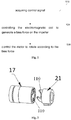
- An embodiment of the present disclosure further provides a control method for disassembling/assembling an impeller of an air conditioner, as shown in Fig. 1 , the control method includes the following steps:
- spiral structure 110 Due to the existence of the spiral structure 110, when a distance between the motor shaft sleeve 21 and the impeller end face shaft sleeve 17 is approached a certain distance, a rotation of the motor is started, both of which are affected by the spiral structure 100 more and more closely until engaged in place. Because the motor is rotating continuously, the matching structure of the two is more and more tightened. When disassembly is required, since the spiral structure 110 is present, only the motor needs to be rotated reversely, and during the reversal, the motor engages with the impeller until disengaged.
- the magnetic polarity of the electromagnetic coil can be changed by controlling a direction of current flowing into the electromagnetic coil, so that the electromagnetic coil attracts or repels the blade, in an exemplary embodiment, controlling the electromagnetic coil to flow into the first direction current, and causing the electromagnetic coil to generate a force applied to the magnetic matching part in a direction away from the motor.
- the electromagnetic coil is controlled to pass a second direction current, so that the electromagnetic coil applies a force to the magnetic matching part to keep the magnetic matching part approach the motor, and the magnetic polarity of the electromagnetic coil is the same as that of the magnetic matching part, the impeller is thus repelled and a force is applied to the impeller in the direction approaching the motor.
- a reset spring is provided between the impeller shaft of the impeller and the electromagnetic coil; the electromagnetic coil applies a force in the direction approaching the motor to the impeller by means of the spring force of the reset spring, in particular the following steps: controlling the electromagnetic coil to be energized; when the electromagnetic coil is energized, the reset spring generates a biasing force toward the motor direction; the electromagnetic coil is controlled to be energized, and when the electromagnetic coil is de-energized, the reset spring releases the bias force on the impeller shaft to reset the impeller shaft to the position where the electromagnetic coil is docked.
- the reset spring is directly connected to the impeller shaft, and during operation of the impeller, the rotation of the impeller may cause a follow-up of the spring, may produce abnormal noise, and may influence the user experience
- the magnetic matching part further includes a connecting cylinder; when the electromagnetic coil applies a force in a direction away from the motor to the impeller shaft, the connecting cylinder moves to a first preset position in a direction away from the motor, and the reset spring is compressed and a movement distance thereof is greater than a movement distance of the impeller shaft, so as to provide an axial room for dismantling the impeller; when the electromagnetic coil applies a force in the direction approaching motor to the impeller shaft, the connecting cylinder is adapted to abut against the impeller shaft and move to a second preset position under the action of the reset spring; controlling the motor to be rotated reversely when the connecting cylinder moves to the first preset position; controlling the motor to be rotated forward when the connecting cylinder moves to the second preset position.
- the first preset position may be an
- the motor By controlling the electromagnetic coil to control the direction in which the acting force is applied to the impeller, incorporating forward rotation or reverse rotation of the motor, the motor is rotated reversely when controlling the electromagnetic coil to apply the acting force away from the motor to the impeller, the impeller is automatically separated from the motor, and when controlling the electromagnetic coil to apply the acting force toward the motor to the impeller, the motor is rotated forward and the impeller is automatically engaged with the motor, so that the impeller can be automatically disassembled or mounted, thereby reducing manual operation and improving working efficiency.
- An embodiment of the present disclosure further provides an air conditioner, as shown in Fig. 3 , a modular air conditioner indoor unit of the present disclosure, including a base module 100, a heat exchange module 200, an air duct module 300 and an appearance module 400.
- the disassemble and assemble structure includes: a magnetic matching part 11 provided at one end, away from the motor 20, of the impeller 10; and an electromagnetic coil 12 disposed on an adjacent component adjacent to the magnetic matching part 11, the electromagnetic coil 12 generates a biasing force with the magnetic matching part for applying a force away from or toward the direction of the motor 20 to the impeller 10.
- the magnetic matching part 11 provided on an end face of one end, away from the motor 20, of the impeller 10 may be an iron ring or an injection molded piece or a metal magnetic material of an iron sheet or a magnetic material.
- the electromagnetic coil 12 may generate a magnetic fit with the magnetic matching part 11 by changing the direction of current.
- the opposite surface of the magnetic matching component 11 and the electromagnetic coil 12 is a magnetic positive pole, when a forward current is applied, an end, opposite to the magnetic matching part 11, of the electromagnetic coil 12 is a magnetic positive pole, and the electromagnetic coil 12 may generate a force toward the direction of the motor 20 on the impeller 10, and when a reverse current is applied thereto.
- One end, opposite to the magnetic matching part 11, of the electromagnetic coil 12 is a magnetic negative pole, and the electromagnetic coil 12 can generate a force away from the electric motor 20 on the impeller 10.
- the magnetic matching part 11 is a metal that can be attracted by a magnetic material, such as iron or nickel, to ensure that the electromagnetic coil 12 applies a force in a direction toward the motor 20 to the impeller 10, in an exemplary embodiment, as shown in Fig. 7 , the disassemble and assemble structure can further include a reset spring 13 disposed between the impeller shaft 15 and the electromagnetic coil 12, when the electromagnetic coil 12 is energized, a biasing force is generated toward the direction of the motor 20, and when the electromagnetic coil 12 is de-energized, the biasing force is released to the impeller shaft 15 for restoring the impeller shaft 15 at a position docked with the motor 20. Under normal operation of the impeller 10, the reset spring 13 is in a natural state.
- the reset spring 13 is directly connected to the impeller shaft 15, and during operation of the impeller 10, the rotation of the impeller 10 may cause a follow-up of the spring, may produce abnormal noise and may cause an influence to the user experience.
- the magnetic matching part 11 further includes a connecting cylinder 14 provided between the impeller shaft 15 and the reset spring 13.
- a magnetic matching part provided at one end, away from the motor, of the impeller; and an electromagnetic coil disposed on an adjacent component adjacent to the magnetic matching part, the electromagnetic coil and the magnetic matching part generating a magnetic fitting for applying a force away from or toward the direction of the motor to the impeller.
- One end of the impeller can be automatically removed by controlling the electromagnetic coil, so that manual removal can be saved, and automatic separation between the impeller and the motor, automatic separation between the impeller and bottom shell can be realized.
- the efficiency of the air conditioner operation can be improved.
- the air conditioner can further include a control mechanism.
- the control mechanism includes a memory 50 and a processor 60, the motor 20, the electromagnetic coil 12, the memory 50 and the processor 60 are connected to each other by a bus, a computer instruction is stored in the memory, and the processor 60 executes the computer instruction by using the control method of the impeller described in any one of the above embodiments with the disassemble and assemble structure described in any one of said air conditioners.
Landscapes
- Engineering & Computer Science (AREA)
- Mechanical Engineering (AREA)
- General Engineering & Computer Science (AREA)
- Chemical & Material Sciences (AREA)
- Combustion & Propulsion (AREA)
- Structures Of Non-Positive Displacement Pumps (AREA)
Abstract
Description
- The present disclosure relates to a technical field of air conditioner, and in particular, to an air conditioner and a control method for disassembling and assembling an impeller of an air conditioner.
- The air conditioner acts as a commonly used household appliance, the key components of which lie in an air duct system. During the long-term use of the air conditioner, dopants such as dust entering an air passage and a water passage from an air inlet severely contaminate the whole air passage and a water passage system, and if the cleaning is not performed in time, the environment will be compromised during the operation of the air conditioner as a contamination source, thereby greatly harming the health of the user.
- Traditional air conditioners, the air duct and water duct system and the bottom shell of the air conditioner as a whole, and the air duct and water duct system are firstly fitted and fixed as base parts, and if washing is required, a specialized person needs to disassemble each part of the air conditioner and then disassemble and clean the part, thereby complicating disassembly.
- In Chinese patent
CN2823621Y , a fan device of a household appliance is disclosed, and the fan device is mounted on a rack, and includes a coupling device, the coupling device comprising an impeller nesting embedded in a center of another end face of the fan and a motor shaft nesting fixedly mounted on a main shaft of a drive motor. One or more mounting grooves are disposed in the impeller nesting, and one or more mounting clamps are disposed in the motor shaft nesting, and when the fan needs to be removed for cleaning and mounting, the fan needs to be manually shifted, and the fan moves a certain distance in the axial direction of the fan end, and the fan itself is heavier. When in use, a large force of air is required to be dialed, and during disassembly or installation, the windmill and the motor are not easily separated and installed. - The technical problem to be solved by an embodiment of the present disclosure is that the blades and the motor are not easily installed or separated in the prior art, and further provided is a disassemble and assemble structure for an impeller and a motor, and a control method therefor, and an air conditioner with a longer service life.
- According to a first aspect, an embodiment of the present disclosure provides a control method for disassembling and assembling an impeller of an air conditioner, including the following steps: controlling the electromagnetic coil to generate a biasing force on the impeller, the biasing force including: a force acting on the impeller to keep the impeller away from or toward a motor; the motor is controlled to rotate according to the bias force to separate or engage the impeller from the motor.
- In an exemplary embodiment, the bias force is a force acting on the impeller in a direction away from the motor; controlling the motor to rotate according to the biasing force includes: controlling the motor to rotate reversely according to the bias force to separate the impeller from the motor; or the bias force is a force acting on the impeller in a direction away from the motor; controlling the motor to rotate according to the biasing force includes: controlling the motor to rotate forward according to the biasing force to engage the impeller with the motor.
- In an exemplary embodiment, the step of controlling the electromagnetic coil to generate the bias force on the impeller includes: controlling the electromagnetic coil to energize so that the electromagnetic coil applies a force in a direction away from the motor to the impeller; or controlling the electromagnetic coil to be de-energized so that a reset spring installed between the electromagnetic coil and the impeller applies a force in a direction close to the motor to the impeller.
- In an exemplary embodiment, the step of controlling the electromagnetic coil to generate the bias force on the impeller includes: controlling the electromagnetic coil to apply a first direction current so that the electromagnetic coil applies a force in a direction away from the motor to the magnetic matching part mounted on the side, close to the electromagnetic coil, of the impeller; or, controlling the electromagnetic coil to apply a second direction current so that the electromagnetic coil applies a force in a direction toward the motor to the magnetic matching part.
- In an exemplary embodiment, before controlling the electromagnetic coil to generate the bias force on the impeller, the control method includes: acquiring a control signal, wherein the control signal includes a disassembly control signal or an assembly control signal.
- According to a second aspect, an embodiment of the present disclosure provides an air conditioner, including: an impeller having an impeller shaft rotatably disposed on a bottom housing component, wherein a disassemble and assemble structure is disposed at an end, away from the motor, of the impeller, and the disassemble and assemble structure includes: an electromagnetic coil generates a biasing force on the impeller, and the biasing force includes: a force acting on the impeller to keep the impeller away from or toward a motor, the electromagnetic coil being provided on an adjacent part adjacent to the impeller; and a controller controlling the motor to rotate according to the biasing force to disengage or engage the impeller with the motor.
- In an exemplary embodiment, the bias force is a force acting on the impeller to keep the impeller away from the motor; the controller controls the motor to rotate reversely according to the bias force, so as to separate the impeller from the motor; or the bias force is a force acting on the impeller to keep the impeller away from the motor; and the controller controls the motor to rotate forward according to the bias force, so as to engage the impeller with the motor.
- In an exemplary embodiment, the air conditioner further includes: a reset spring disposed between the electromagnetic coil and the impeller, when the controller controls the electromagnetic coil to be energized, an acting force in the direction approaching the motor is generated, when the controller controls the electromagnetic coil to be powered off, the controller releases a force to the impeller shaft, a position for restoring the impeller shaft to dock with the motor.
- In an exemplary embodiment, the air conditioner further includes: a magnetic matching part installed on a side, close to the electromagnetic coil, of the impeller; and when the controller controls the electromagnetic coil to apply the first direction current, applying a force in a direction away from the motor to the magnetic matching part, when the controller controls the electromagnetic coil to apply the second direction current, a force in the direction approaching the motor is applied to the magnetic matching part, and the impeller shaft is restored to a position docked with the motor.
- In an exemplary embodiment, the air conditioner further includes: an acquisition module, configured to acquire a control signal, wherein the control signal includes a disassembly control signal or an installation control signal.
- According to the method for controlling impeller disassembly of an air conditioner and the air conditioner provided by the embodiments of the present disclosure, the direction of the electromagnetic coil controlling the application of the acting force to the impeller is controlled, and when the electromagnetic coil is controlled to apply the acting force away from the impeller, the motor is reversed to automatically separate the impeller from the motor. When the electromagnetic coil is controlled to apply a force to the impeller toward the motor, the motor is transmitting to automatically engage the impeller with the motor, so that the impeller can be automatically detached or mounted, thereby reducing manual operation and improving working efficiency.
- To illustrate the technical solutions in the embodiments of the present disclosure or in the prior art more clearly, the following briefly introduces the accompanying drawings required for describing the embodiments or the prior art. Obviously, the accompanying drawings in the following description are some embodiments of the present disclosure. For a person of ordinary skill in the art, other drawings can be obtained from these drawings without creative efforts.
-
Fig. 1 is a schematic flowchart of a control method for disassembling and assembling an impeller of an air conditioner according to an embodiment of the present disclosure; -
Fig. 2 is a schematic diagram showing a cooperation structure of an impeller and a motor according to an embodiment of the present disclosure; -
Fig. 3 shows a schematic diagram of an air conditioner module according to an embodiment of the present disclosure; -
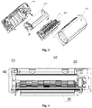
Fig. 4 is a schematic structural diagram of an air duct module according to an embodiment of the present disclosure; -
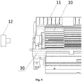
Fig. 5 shows a schematic diagram of a disassemble and assemble structure for an impeller and a motor according to an embodiment of the present disclosure; -
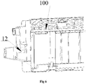
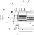
Fig. 6 shows a schematic diagram of a mounting position of an electromagnetic coil according to an embodiment of the present disclosure; -
Fig. 7 shows another schematic diagram of a disassemble and assemble structure for an impeller and a motor according to an embodiment of the present disclosure; -
Fig. 8 shows another schematic diagram of a disassemble and assemble structure for an impeller and an electric motor according to an embodiment of the present disclosure; -
Fig. 9 shows a schematic diagram of a connecting cylinder and an impeller cooperating structure according to an embodiment of the present disclosure; -
Fig. 10 shows a control mechanism of an air conditioner according to an embodiment of the present disclosure. - In the drawings,
10, impeller; 11, magnetic matching part; 12, electromagnetic coil; 13, reset spring; 14, connecting cylinder; 15, impeller shaft; 20, motor; 16, shaft cover; 17, impeller end face sleeve; 18, shaft hole; 21, motor shaft cover; 110, helical structure; 50, memory; 60, processor. - The technical solutions of the present disclosure will be clearly and completely described below with reference to the accompanying drawings, and obviously, the described embodiments are a part of the embodiments of the present disclosure rather than all of the embodiments. Based on the embodiments of the present disclosure, all other embodiments be obtained by those skilled in the art without creative efforts fall within the scope of protection of the present disclosure.
- In the description of the present disclosure, it should be noted that the terms "installation", "connection" and "connection" should be understood broadly, for example, may be a fixed connection, may also be a detachable connection, or may be integrally connected, unless otherwise specified and defined. may be a mechanical connection or an electrical connection; The communication may be a direct connection or an indirect connection via an intermediate medium, or an internal connection of two elements, or a wireless connection or a wired connection. For a person of ordinary skill in the art, the specific meaning of the above terms in the present disclosure can be understood in particular.
- An embodiment of the present disclosure further provides a control method for disassembling/assembling an impeller of an air conditioner, as shown in
Fig. 1 , the control method includes the following steps: - S11. Acquire a control signal. In the present embodiment, the control signal includes a disassembly control signal or an assembly control signal. In a specific embodiment, when the user needs to clean the air conditioner, the impeller needs to be dismounted, the user or the operator sends a disassembly control signal, where the disassembly control signal may be a cleaning instruction sent by the user, or the disassembly signal sent by the operator during maintenance. The specific disassembly control signal may be sent to a receiving end of the air conditioner through a remote controller or terminal, and the impeller is reinstalled after cleaning or repair is completed, the user or operator may send an assembly control signal through the remote controller or terminal, and the receiving end transmits the disassembly control signal or the assembly control signal to the controller.
- S12, controlling the electromagnetic coil to generate a bias force to the impeller. In a specific embodiment, the control electromagnetic coil generates a magnetic attraction force to attract the magnetic matching part, and since the magnetic matching part is provided on the impeller, that is, the electromagnetic coil attracts the impeller; a force in a direction away from the motor is applied to the impeller. After receiving the mounting signal, the electromagnetic coil is controlled to generate a repulsive force that repels magnetic matching part, specifically, the repulsive force may be a magnetic repulsive force, or may be an elastic force or other thrust force. A force is applied in a direction approaching the motor to the impeller.
- S13, controlling the motor to rotate according to the bias force. In a specific embodiment, after receiving the disassembly signal, an acting force in a direction away from the motor is applied to the impeller, and the motor is controlled to be rotated reversely to separate the motor from the impeller. After receiving the assembly signal, applying a force in the direction of approaching the motor to the impeller, and pushing the impeller close to the motor until the engageable distance is reached, and controlling the motor to rotate reversely, so as to engage the impeller with the motor. In the present embodiment, as shown in
Fig. 2 , a moving surface of amotor shaft sleeve 21 and an impeller endface shaft sleeve 17 are designed as aspiral structure 110, so that during operation, an axial force exists on a matching surface of the impeller endface shaft sleeve 17 and themotor shaft sleeve 21, and this axial force makes the impeller firmly operate without departing from themotor shaft sleeve 21. - Due to the existence of the
spiral structure 110, when a distance between themotor shaft sleeve 21 and the impeller endface shaft sleeve 17 is approached a certain distance, a rotation of the motor is started, both of which are affected by thespiral structure 100 more and more closely until engaged in place. Because the motor is rotating continuously, the matching structure of the two is more and more tightened. When disassembly is required, since thespiral structure 110 is present, only the motor needs to be rotated reversely, and during the reversal, the motor engages with the impeller until disengaged. - In an optional embodiment, when the magnetic matching part on the end face of the impeller is an injection molded piece or a metal magnetic material having a magnetic material, the magnetic polarity of the electromagnetic coil can be changed by controlling a direction of current flowing into the electromagnetic coil, so that the electromagnetic coil attracts or repels the blade, in an exemplary embodiment, controlling the electromagnetic coil to flow into the first direction current, and causing the electromagnetic coil to generate a force applied to the magnetic matching part in a direction away from the motor. During disassembly, the electromagnetic coil is controlled to generate a magnetic polarity opposite to a magnetic polarity of the magnetic matching part, for example, if a side, opposite to the electromagnetic coil, of the magnetic matching part is an N pole, the direction of current flowing through the electromagnetic coil is controlled so that the side, opposite to the magnetic matching part, of the electromagnetic coil generates S pole magnetism, and an acting force in the direction away from the motor is applied to the impeller. During mounting, the electromagnetic coil is controlled to pass a second direction current, so that the electromagnetic coil applies a force to the magnetic matching part to keep the magnetic matching part approach the motor, and the magnetic polarity of the electromagnetic coil is the same as that of the magnetic matching part, the impeller is thus repelled and a force is applied to the impeller in the direction approaching the motor.
- In an exemplary embodiment, a reset spring is provided between the impeller shaft of the impeller and the electromagnetic coil; the electromagnetic coil applies a force in the direction approaching the motor to the impeller by means of the spring force of the reset spring, in particular the following steps: controlling the electromagnetic coil to be energized; when the electromagnetic coil is energized, the reset spring generates a biasing force toward the motor direction; the electromagnetic coil is controlled to be energized, and when the electromagnetic coil is de-energized, the reset spring releases the bias force on the impeller shaft to reset the impeller shaft to the position where the electromagnetic coil is docked.
- The reset spring is directly connected to the impeller shaft, and during operation of the impeller, the rotation of the impeller may cause a follow-up of the spring, may produce abnormal noise, and may influence the user experience, and in an alternative embodiment, the magnetic matching part further includes a connecting cylinder;
when the electromagnetic coil applies a force in a direction away from the motor to the impeller shaft, the connecting cylinder moves to a first preset position in a direction away from the motor, and the reset spring is compressed and a movement distance thereof is greater than a movement distance of the impeller shaft, so as to provide an axial room for dismantling the impeller; when the electromagnetic coil applies a force in the direction approaching motor to the impeller shaft, the connecting cylinder is adapted to abut against the impeller shaft and move to a second preset position under the action of the reset spring; controlling the motor to be rotated reversely when the connecting cylinder moves to the first preset position; controlling the motor to be rotated forward when the connecting cylinder moves to the second preset position. The first preset position may be an axial space for the impeller to be detached, and the second preset position may be a position for the impeller to be automatically engaged with the motor. - By controlling the electromagnetic coil to control the direction in which the acting force is applied to the impeller, incorporating forward rotation or reverse rotation of the motor, the motor is rotated reversely when controlling the electromagnetic coil to apply the acting force away from the motor to the impeller, the impeller is automatically separated from the motor, and when controlling the electromagnetic coil to apply the acting force toward the motor to the impeller, the motor is rotated forward and the impeller is automatically engaged with the motor, so that the impeller can be automatically disassembled or mounted, thereby reducing manual operation and improving working efficiency.
- An embodiment of the present disclosure further provides an air conditioner, as shown in
Fig. 3 , a modular air conditioner indoor unit of the present disclosure, including abase module 100, aheat exchange module 200, anair duct module 300 and anappearance module 400. - As shown in
Fig. 4 , one end of theimpeller 10 is rotatably connected with amotor 20, and the other end is rotatably connected with thebottom shell 310 of theair duct module 300 by using the disassemble and assemble structure, as shown inFig. 5 , the disassemble and assemble structure includes:
amagnetic matching part 11 provided at one end, away from themotor 20, of theimpeller 10; and anelectromagnetic coil 12 disposed on an adjacent component adjacent to themagnetic matching part 11, theelectromagnetic coil 12 generates a biasing force with the magnetic matching part for applying a force away from or toward the direction of themotor 20 to theimpeller 10. In particular embodiments, themagnetic matching part 11 provided on an end face of one end, away from themotor 20, of theimpeller 10 may be an iron ring or an injection molded piece or a metal magnetic material of an iron sheet or a magnetic material. When the end face is an injection molded piece or metal magnetic material of magnetic material, theelectromagnetic coil 12 may generate a magnetic fit with themagnetic matching part 11 by changing the direction of current. For example, the opposite surface of themagnetic matching component 11 and theelectromagnetic coil 12 is a magnetic positive pole, when a forward current is applied, an end, opposite to themagnetic matching part 11, of theelectromagnetic coil 12 is a magnetic positive pole, and theelectromagnetic coil 12 may generate a force toward the direction of themotor 20 on theimpeller 10, and when a reverse current is applied thereto. One end, opposite to themagnetic matching part 11, of theelectromagnetic coil 12 is a magnetic negative pole, and theelectromagnetic coil 12 can generate a force away from theelectric motor 20 on theimpeller 10. - In an exemplary embodiment, as shown in
Fig. 6 , theelectromagnetic coil 12 is mounted on thebase module 100, and may be connected in a structure such as a screw or a snap. Other connecting forms that can be fastened to divert theelectromagnetic coil 12 on thebase module 100 may also be used, which is not limited in the present embodiment. - The
magnetic matching part 11 is a metal that can be attracted by a magnetic material, such as iron or nickel, to ensure that theelectromagnetic coil 12 applies a force in a direction toward themotor 20 to theimpeller 10, in an exemplary embodiment, as shown inFig. 7 , the disassemble and assemble structure can further include areset spring 13 disposed between theimpeller shaft 15 and theelectromagnetic coil 12, when theelectromagnetic coil 12 is energized, a biasing force is generated toward the direction of themotor 20, and when theelectromagnetic coil 12 is de-energized, the biasing force is released to theimpeller shaft 15 for restoring theimpeller shaft 15 at a position docked with themotor 20. Under normal operation of theimpeller 10, thereset spring 13 is in a natural state. - The
reset spring 13 is directly connected to theimpeller shaft 15, and during operation of theimpeller 10, the rotation of theimpeller 10 may cause a follow-up of the spring, may produce abnormal noise and may cause an influence to the user experience. In an alternative embodiment, as shown inFig. 8 , themagnetic matching part 11 further includes a connectingcylinder 14 provided between theimpeller shaft 15 and thereset spring 13. When theelectromagnetic coil 12 applies a force to theimpeller shaft 15 away from the direction of theelectric motor 20, the connectingcylinder 14 also moves and compresses thereset spring 13 in a direction away from themotor 20, and a distance of the connecting cylinder moves is greater than that of theimpeller shaft 15, an axial space for dismantling theimpeller 10 is provided, when theelectromagnetic coil 12 applies a force in the direction approaching themotor 20 to theimpeller shaft 15, the connectingcylinder 14 is adapted to abut against theimpeller shaft 15 under the action of thereset spring 13. As shown inFigs. 9 and4 , one end of the connectingcylinder 14 abuts against thereset spring 13, and the other end is supported in theshaft sleeve 16 for supporting theimpeller shaft 15 at the same time, and the connectingcylinder 14 is movably supported in ashaft hole 18 of theshaft sleeve 16. Theshaft sleeve 16 can achieve centering and lubrication of theimpeller shaft 15. - A magnetic matching part provided at one end, away from the motor, of the impeller; and an electromagnetic coil disposed on an adjacent component adjacent to the magnetic matching part, the electromagnetic coil and the magnetic matching part generating a magnetic fitting for applying a force away from or toward the direction of the motor to the impeller. One end of the impeller can be automatically removed by controlling the electromagnetic coil, so that manual removal can be saved, and automatic separation between the impeller and the motor, automatic separation between the impeller and bottom shell can be realized. Thus, the efficiency of the air conditioner operation can be improved.
- In an exemplary embodiment, as shown in
Fig. 10 , the air conditioner can further include a control mechanism. The control mechanism includes amemory 50 and aprocessor 60, themotor 20, theelectromagnetic coil 12, thememory 50 and theprocessor 60 are connected to each other by a bus, a computer instruction is stored in the memory, and theprocessor 60 executes the computer instruction by using the control method of the impeller described in any one of the above embodiments with the disassemble and assemble structure described in any one of said air conditioners. - While embodiments of the present disclosure have been described in connection with the accompanying drawings, those skilled in the art may make various modifications and variations without departing from the spirit and scope of the present disclosure, such modifications and variations all fall within the scope defined by the appended claims.
Claims (10)
- A control method for disassembling and assembling an impeller of an air conditioner, comprising:controlling an electromagnetic coil to generate a biasing force on the impeller, the biasing force comprising: a force acting on the impeller to keep the impeller away from or toward a motor;controlling the motor to rotate according to the biasing force to separate or engage the impeller with the motor.
- The control method for disassembling and assembling the impeller of the air conditioner according to claim 1, wherein:the biasing force is a force acting on the impeller in a direction away from the motor;the controlling the motor to rotate according to the bias force comprises:controlling the motor to rotate reversely according to the bias force to separate the impeller from the motor; or,the biasing force is a force acting on the impeller in a direction away from the motor;the controlling the motor to rotate according to the bias force comprises:
controlling the motor to forward rotate according to the bias force to engage the impeller with the motor. - The control method for disassembling and assembling the impeller of the air conditioner according to claim 1 or 2, wherein the controlling the electromagnetic coil to generate the bias force on the impeller comprises:controlling the electromagnetic coil to be energized so that the electromagnetic coil applies a force in a direction away from the motor to the impeller; orcontrolling the electromagnetic coil to be de-energized so that a reset spring installed between the electromagnetic coil and the impeller applies a force in a direction close to the motor to the impeller.
- The control method for disassembling and assembling the impeller of the air conditioner according to claim 1 or 2, wherein the controlling the electromagnetic coil to generate a bias force on the impeller comprises:controlling the electromagnetic coil to apply a first direction current so that the electromagnetic coil applies a force in a direction away from the motor to a magnetic matching part mounted on a side, close to the electromagnetic coil, of the impeller; or,controlling the electromagnetic coil to apply a second direction current so that the electromagnetic coil applies a force in a direction toward the motor to the magnetic matching part.
- The control method for disassembling and assembling the impeller of the air conditioner according to claim 1 or 2, wherein before the controlling the electromagnetic coil to generate a bias force on the impeller, the control method comprises:
acquiring a control signal, wherein the control signal comprises a disassembly control signal or an assembly control signal. - An air conditioner, comprising:an impeller having an impeller shaft rotatably disposed on a bottom housing component, whereina disassemble and assemble structure is arranged at one end, away from the motor, of the impeller, and the disassemble and assemble structure comprises:an electromagnetic coil, the electromagnetic coil generating a biasing force on the impeller, the biasing force comprising: a force acting on the impeller to keep the impeller away from or toward a motor, the electromagnetic coil being disposed on an adjacent part adjacent to the impeller;anda controller, the controller controlling the motor to rotate according to the biasing force to disengage or engage the impeller with the motor.
- The air conditioner according to claim 6, wherein:the biasing force is a force acting on the impeller to keep the impeller away from the motor;the controller controls the motor to rotate reversely according to the biasing force, so as to separate the impeller from the motor; or,the biasing force is a force acting on the impeller to keep the impeller away from the motor;and the controller controls the motor to rotate forward according to the bias force, so as to engage the impeller with the motor.
- The air conditioner according to claim 6 or 7, further comprising:
a reset spring disposed between the electromagnetic coil and the impeller, when the controller controls the electromagnetic coil to be energized, generating an acting force in a direction approaching the motor; releasing the acting force to the impeller shaft when the controller controls the electromagnetic coil to be powered off; a position for restoring the impeller shaft to dock with the motor. - The air conditioner according to claim 6 or 7, further comprising:
a magnetic matching part installed on a side, close to the electromagnetic coil, of the impeller, and when the controller controls the electromagnetic coil to apply the first direction current, applying a force in a direction away from the motor to the magnetic matching part, and when the controller controls the electromagnetic coil to apply the second direction current, applying a force in a direction approaching the motor to the magnetic matching part to restore the impeller shaft to a position docked with the motor. - The air conditioner according to claim 6 or 7, further comprising:
an acquisition module, configured to acquire a control signal, wherein the control signal comprises a disassembly control signal or an assembly control signal.
Applications Claiming Priority (2)
| Application Number | Priority Date | Filing Date | Title |
|---|---|---|---|
| CN201710286542.3A CN108799196B (en) | 2017-04-26 | 2017-04-26 | Air conditioner impeller dismounting/mounting control method and air conditioner |
| PCT/CN2017/118322 WO2018196420A1 (en) | 2017-04-26 | 2017-12-25 | Control method for assembling or disassembling impeller of air conditioner, and air conditioner |
Publications (3)
| Publication Number | Publication Date |
|---|---|
| EP3617526A1 true EP3617526A1 (en) | 2020-03-04 |
| EP3617526A4 EP3617526A4 (en) | 2021-01-13 |
| EP3617526B1 EP3617526B1 (en) | 2026-02-11 |
Family
ID=63918016
Family Applications (1)
| Application Number | Title | Priority Date | Filing Date |
|---|---|---|---|
| EP17907360.6A Active EP3617526B1 (en) | 2017-04-26 | 2017-12-25 | Control method for assembling or disassembling impeller of air conditioner, and air conditioner |
Country Status (3)
| Country | Link |
|---|---|
| EP (1) | EP3617526B1 (en) |
| CN (1) | CN108799196B (en) |
| WO (1) | WO2018196420A1 (en) |
Families Citing this family (2)
| Publication number | Priority date | Publication date | Assignee | Title |
|---|---|---|---|---|
| CN111219360B (en) * | 2018-11-27 | 2022-08-02 | 广东美的环境电器制造有限公司 | Wind wheel device and household appliance |
| CN111121174B (en) * | 2020-01-16 | 2024-03-29 | 珠海格力电器股份有限公司 | Fan assembly, window air conditioner and control method of window air conditioner |
Family Cites Families (18)
| Publication number | Priority date | Publication date | Assignee | Title |
|---|---|---|---|---|
| JPH04126926A (en) * | 1990-09-19 | 1992-04-27 | Mitsubishi Electric Corp | Air conditioner |
| CN2185861Y (en) * | 1993-11-13 | 1994-12-21 | 成都市工业合作联社 | Air conditioner with humidifier |
| JP3117944B2 (en) * | 1997-10-29 | 2000-12-18 | 三菱電機株式会社 | Blower |
| US6247324B1 (en) * | 2000-03-07 | 2001-06-19 | Chien-Chih Hsu | Air conditioning apparatus with a water pump |
| CN2544877Y (en) * | 2002-03-04 | 2003-04-16 | 长沙海赛新技术有限公司 | Fan impeller demounting device |
| CN2713363Y (en) * | 2004-07-06 | 2005-07-27 | 广东科龙电器股份有限公司 | Switch assembly for air exhaust door of indoor set of air conditioner |
| CN2823621Y (en) | 2005-07-22 | 2006-10-04 | 珠海格力电器股份有限公司 | fan device of household appliance |
| TW201318889A (en) * | 2011-11-02 | 2013-05-16 | Dmp Electronics Inc | Omnidirectional wheel for convenient disassembly and assembly and omnidirectional wheel set |
| DE102012018968A1 (en) * | 2012-09-26 | 2013-03-14 | Daimler Ag | Puller device for disassembling bearing arrangement for supporting wheel of lorry, has disassembly fixing device fixed to mounting device of arrangement at auxiliary fixing device for transferring peel force by disassembly fixing device |
| JP6207454B2 (en) * | 2014-04-17 | 2017-10-04 | 三菱電機株式会社 | Air conditioner indoor unit |
| CN104482596B (en) * | 2014-11-13 | 2017-04-12 | 游飞 | Wall-mounted indoor air-conditioner easy to mount and demount |
| CN106194849B (en) * | 2015-04-30 | 2024-04-09 | 贵州盘江矿山机械有限公司 | Draught fan rotor impeller dismounting device |
| CN205714939U (en) * | 2016-05-06 | 2016-11-23 | 宁波方太厨具有限公司 | A kind of centrifugal blower of impeller fast demountable |
| CN205817716U (en) * | 2016-06-15 | 2016-12-21 | 天津钢管集团股份有限公司 | Water ring vacuum pump vane tool special for dismounting |
| CN205897337U (en) * | 2016-07-12 | 2017-01-18 | 宁波奥克斯空调有限公司 | Wall air conditioner indoor set of readily removable |
| WO2018137419A1 (en) * | 2017-01-25 | 2018-08-02 | 珠海格力电器股份有限公司 | Impeller assembly and air conditioner |
| CN206682170U (en) * | 2017-03-16 | 2017-11-28 | 珠海格力电器股份有限公司 | Bearing seat assembly and air conditioner thereof |
| CN106917828B (en) * | 2017-03-16 | 2019-08-30 | 珠海格力电器股份有限公司 | Bearing seat assembly and air conditioner thereof |
-
2017
- 2017-04-26 CN CN201710286542.3A patent/CN108799196B/en active Active
- 2017-12-25 EP EP17907360.6A patent/EP3617526B1/en active Active
- 2017-12-25 WO PCT/CN2017/118322 patent/WO2018196420A1/en not_active Ceased
Also Published As
| Publication number | Publication date |
|---|---|
| CN108799196A (en) | 2018-11-13 |
| WO2018196420A1 (en) | 2018-11-01 |
| CN108799196B (en) | 2020-10-16 |
| EP3617526B1 (en) | 2026-02-11 |
| EP3617526A4 (en) | 2021-01-13 |
Similar Documents
| Publication | Publication Date | Title |
|---|---|---|
| EP3617526B1 (en) | Control method for assembling or disassembling impeller of air conditioner, and air conditioner | |
| EP3617525B1 (en) | Impeller assembly, and air conditioner for same | |
| CN112594794B (en) | Cleaning device, cleaning method, outdoor unit and air conditioner | |
| WO2018166198A1 (en) | Bearing housing assembly and air conditioner therewith | |
| WO2019161695A1 (en) | Air duct assembly and air conditioner | |
| CN109611921B (en) | grease pump | |
| CN213272868U (en) | Air conditioner and its indoor unit | |
| CN201407192Y (en) | A Portable Household DC Brushless Fan | |
| EP3777523B1 (en) | Garden hose on/off timer unit with viewing angle adjustable display panel | |
| CN114688609A (en) | Air supply device and air conditioner | |
| WO2018137380A1 (en) | Air-conditioner | |
| CN208010613U (en) | Air duct assembly and air conditioner | |
| CN216077631U (en) | Controllable impeller in clearance | |
| CN218001720U (en) | New trend system impurity intercepting device | |
| CN211575277U (en) | A kind of air conditioner cross-flow fan blade automatic separation device and air conditioner | |
| CN217814184U (en) | Convenient air suspension centrifugal fan filtration who changes | |
| CN215412165U (en) | Air conditioner | |
| CN105737275B (en) | Fan assembly and air conditioner | |
| CN219081884U (en) | Fan and gas water heater | |
| CN209605234U (en) | Smoke exhaust ventilator | |
| CN209310218U (en) | Connecting assembly and air conditioner with same | |
| CN110864372B (en) | Automatic separating device and control method for cross-flow fan blades of air conditioner and air conditioner | |
| EP3638916A1 (en) | Hybrid apparatus for controlling the rotation of a fan for cooling the cooling fluid of a vehicle | |
| CN219840810U (en) | Ventilation fan convenient to assemble | |
| CN209341382U (en) | Air conditioner |
Legal Events
| Date | Code | Title | Description |
|---|---|---|---|
| STAA | Information on the status of an ep patent application or granted ep patent |
Free format text: STATUS: THE INTERNATIONAL PUBLICATION HAS BEEN MADE |
|
| PUAI | Public reference made under article 153(3) epc to a published international application that has entered the european phase |
Free format text: ORIGINAL CODE: 0009012 |
|
| STAA | Information on the status of an ep patent application or granted ep patent |
Free format text: STATUS: REQUEST FOR EXAMINATION WAS MADE |
|
| 17P | Request for examination filed |
Effective date: 20190729 |
|
| AK | Designated contracting states |
Kind code of ref document: A1 Designated state(s): AL AT BE BG CH CY CZ DE DK EE ES FI FR GB GR HR HU IE IS IT LI LT LU LV MC MK MT NL NO PL PT RO RS SE SI SK SM TR |
|
| AX | Request for extension of the european patent |
Extension state: BA ME |
|
| DAV | Request for validation of the european patent (deleted) | ||
| DAX | Request for extension of the european patent (deleted) | ||
| REG | Reference to a national code |
Ref country code: DE Ref legal event code: R079 Free format text: PREVIOUS MAIN CLASS: F04D0029260000 Ipc: F04D0017040000 |
|
| A4 | Supplementary search report drawn up and despatched |
Effective date: 20201216 |
|
| RIC1 | Information provided on ipc code assigned before grant |
Ipc: F04D 17/04 20060101AFI20201210BHEP Ipc: F24F 1/0025 20190101ALI20201210BHEP Ipc: F04D 29/28 20060101ALI20201210BHEP Ipc: F04D 29/62 20060101ALI20201210BHEP |
|
| STAA | Information on the status of an ep patent application or granted ep patent |
Free format text: STATUS: EXAMINATION IS IN PROGRESS |
|
| 17Q | First examination report despatched |
Effective date: 20220601 |
|
| P01 | Opt-out of the competence of the unified patent court (upc) registered |
Effective date: 20230530 |
|
| GRAP | Despatch of communication of intention to grant a patent |
Free format text: ORIGINAL CODE: EPIDOSNIGR1 |
|
| STAA | Information on the status of an ep patent application or granted ep patent |
Free format text: STATUS: GRANT OF PATENT IS INTENDED |
|
| INTG | Intention to grant announced |
Effective date: 20250915 |
|
| RAP3 | Party data changed (applicant data changed or rights of an application transferred) |
Owner name: GREE ELECTRIC APPLIANCES (WUHAN) CO., LTD Owner name: GREE ELECTRIC APPLIANCES, INC. OF ZHUHAI |
|
| GRAS | Grant fee paid |
Free format text: ORIGINAL CODE: EPIDOSNIGR3 |
|
| GRAA | (expected) grant |
Free format text: ORIGINAL CODE: 0009210 |
|
| STAA | Information on the status of an ep patent application or granted ep patent |
Free format text: STATUS: THE PATENT HAS BEEN GRANTED |
|
| AK | Designated contracting states |
Kind code of ref document: B1 Designated state(s): AL AT BE BG CH CY CZ DE DK EE ES FI FR GB GR HR HU IE IS IT LI LT LU LV MC MK MT NL NO PL PT RO RS SE SI SK SM TR |
|
| REG | Reference to a national code |
Ref country code: CH Ref legal event code: F10 Free format text: ST27 STATUS EVENT CODE: U-0-0-F10-F00 (AS PROVIDED BY THE NATIONAL OFFICE) Effective date: 20260211 Ref country code: GB Ref legal event code: FG4D |
|
| REG | Reference to a national code |
Ref country code: DE Ref legal event code: R096 Ref document number: 602017093879 Country of ref document: DE |
|
| REG | Reference to a national code |
Ref country code: IE Ref legal event code: FG4D |