EP3617459A2 - Method of forming a gas turbine component formed of laminate and blade outer air seal - Google Patents
Method of forming a gas turbine component formed of laminate and blade outer air seal Download PDFInfo
- Publication number
- EP3617459A2 EP3617459A2 EP19194470.1A EP19194470A EP3617459A2 EP 3617459 A2 EP3617459 A2 EP 3617459A2 EP 19194470 A EP19194470 A EP 19194470A EP 3617459 A2 EP3617459 A2 EP 3617459A2
- Authority
- EP
- European Patent Office
- Prior art keywords
- set forth
- air seal
- layer
- cooling circuits
- forming
- Prior art date
- Legal status (The legal status is an assumption and is not a legal conclusion. Google has not performed a legal analysis and makes no representation as to the accuracy of the status listed.)
- Granted
Links
Images





Classifications
-
- F—MECHANICAL ENGINEERING; LIGHTING; HEATING; WEAPONS; BLASTING
- F01—MACHINES OR ENGINES IN GENERAL; ENGINE PLANTS IN GENERAL; STEAM ENGINES
- F01D—NON-POSITIVE DISPLACEMENT MACHINES OR ENGINES, e.g. STEAM TURBINES
- F01D11/00—Preventing or minimising internal leakage of working-fluid, e.g. between stages
- F01D11/08—Preventing or minimising internal leakage of working-fluid, e.g. between stages for sealing space between rotor blade tips and stator
-
- B—PERFORMING OPERATIONS; TRANSPORTING
- B32—LAYERED PRODUCTS
- B32B—LAYERED PRODUCTS, i.e. PRODUCTS BUILT-UP OF STRATA OF FLAT OR NON-FLAT, e.g. CELLULAR OR HONEYCOMB, FORM
- B32B18/00—Layered products essentially comprising ceramics, e.g. refractory products
-
- C—CHEMISTRY; METALLURGY
- C04—CEMENTS; CONCRETE; ARTIFICIAL STONE; CERAMICS; REFRACTORIES
- C04B—LIME, MAGNESIA; SLAG; CEMENTS; COMPOSITIONS THEREOF, e.g. MORTARS, CONCRETE OR LIKE BUILDING MATERIALS; ARTIFICIAL STONE; CERAMICS; REFRACTORIES; TREATMENT OF NATURAL STONE
- C04B35/00—Shaped ceramic products characterised by their composition; Ceramics compositions; Processing powders of inorganic compounds preparatory to the manufacturing of ceramic products
- C04B35/622—Forming processes; Processing powders of inorganic compounds preparatory to the manufacturing of ceramic products
- C04B35/626—Preparing or treating the powders individually or as batches ; preparing or treating macroscopic reinforcing agents for ceramic products, e.g. fibres; mechanical aspects section B
- C04B35/628—Coating the powders or the macroscopic reinforcing agents
- C04B35/62844—Coating fibres
- C04B35/62857—Coating fibres with non-oxide ceramics
- C04B35/62865—Nitrides
- C04B35/62868—Boron nitride
-
- F—MECHANICAL ENGINEERING; LIGHTING; HEATING; WEAPONS; BLASTING
- F01—MACHINES OR ENGINES IN GENERAL; ENGINE PLANTS IN GENERAL; STEAM ENGINES
- F01D—NON-POSITIVE DISPLACEMENT MACHINES OR ENGINES, e.g. STEAM TURBINES
- F01D11/00—Preventing or minimising internal leakage of working-fluid, e.g. between stages
- F01D11/08—Preventing or minimising internal leakage of working-fluid, e.g. between stages for sealing space between rotor blade tips and stator
- F01D11/14—Adjusting or regulating tip-clearance, i.e. distance between rotor-blade tips and stator casing
- F01D11/20—Actively adjusting tip-clearance
- F01D11/24—Actively adjusting tip-clearance by selectively cooling-heating stator or rotor components
-
- F—MECHANICAL ENGINEERING; LIGHTING; HEATING; WEAPONS; BLASTING
- F01—MACHINES OR ENGINES IN GENERAL; ENGINE PLANTS IN GENERAL; STEAM ENGINES
- F01D—NON-POSITIVE DISPLACEMENT MACHINES OR ENGINES, e.g. STEAM TURBINES
- F01D25/00—Component parts, details, or accessories, not provided for in, or of interest apart from, other groups
- F01D25/005—Selecting particular materials
-
- F—MECHANICAL ENGINEERING; LIGHTING; HEATING; WEAPONS; BLASTING
- F01—MACHINES OR ENGINES IN GENERAL; ENGINE PLANTS IN GENERAL; STEAM ENGINES
- F01D—NON-POSITIVE DISPLACEMENT MACHINES OR ENGINES, e.g. STEAM TURBINES
- F01D25/00—Component parts, details, or accessories, not provided for in, or of interest apart from, other groups
- F01D25/08—Cooling; Heating; Heat-insulation
- F01D25/12—Cooling
-
- C—CHEMISTRY; METALLURGY
- C04—CEMENTS; CONCRETE; ARTIFICIAL STONE; CERAMICS; REFRACTORIES
- C04B—LIME, MAGNESIA; SLAG; CEMENTS; COMPOSITIONS THEREOF, e.g. MORTARS, CONCRETE OR LIKE BUILDING MATERIALS; ARTIFICIAL STONE; CERAMICS; REFRACTORIES; TREATMENT OF NATURAL STONE
- C04B2235/00—Aspects relating to ceramic starting mixtures or sintered ceramic products
- C04B2235/02—Composition of constituents of the starting material or of secondary phases of the final product
- C04B2235/50—Constituents or additives of the starting mixture chosen for their shape or used because of their shape or their physical appearance
- C04B2235/52—Constituents or additives characterised by their shapes
- C04B2235/5208—Fibers
- C04B2235/5216—Inorganic
- C04B2235/524—Non-oxidic, e.g. borides, carbides, silicides or nitrides
- C04B2235/5244—Silicon carbide
-
- C—CHEMISTRY; METALLURGY
- C04—CEMENTS; CONCRETE; ARTIFICIAL STONE; CERAMICS; REFRACTORIES
- C04B—LIME, MAGNESIA; SLAG; CEMENTS; COMPOSITIONS THEREOF, e.g. MORTARS, CONCRETE OR LIKE BUILDING MATERIALS; ARTIFICIAL STONE; CERAMICS; REFRACTORIES; TREATMENT OF NATURAL STONE
- C04B2237/00—Aspects relating to ceramic laminates or to joining of ceramic articles with other articles by heating
- C04B2237/30—Composition of layers of ceramic laminates or of ceramic or metallic articles to be joined by heating, e.g. Si substrates
- C04B2237/32—Ceramic
- C04B2237/38—Fiber or whisker reinforced
-
- F—MECHANICAL ENGINEERING; LIGHTING; HEATING; WEAPONS; BLASTING
- F01—MACHINES OR ENGINES IN GENERAL; ENGINE PLANTS IN GENERAL; STEAM ENGINES
- F01D—NON-POSITIVE DISPLACEMENT MACHINES OR ENGINES, e.g. STEAM TURBINES
- F01D25/00—Component parts, details, or accessories, not provided for in, or of interest apart from, other groups
- F01D25/24—Casings; Casing parts, e.g. diaphragms, casing fastenings
- F01D25/246—Fastening of diaphragms or stator-rings
-
- F—MECHANICAL ENGINEERING; LIGHTING; HEATING; WEAPONS; BLASTING
- F05—INDEXING SCHEMES RELATING TO ENGINES OR PUMPS IN VARIOUS SUBCLASSES OF CLASSES F01-F04
- F05D—INDEXING SCHEME FOR ASPECTS RELATING TO NON-POSITIVE-DISPLACEMENT MACHINES OR ENGINES, GAS-TURBINES OR JET-PROPULSION PLANTS
- F05D2230/00—Manufacture
- F05D2230/90—Coating; Surface treatment
-
- F—MECHANICAL ENGINEERING; LIGHTING; HEATING; WEAPONS; BLASTING
- F05—INDEXING SCHEMES RELATING TO ENGINES OR PUMPS IN VARIOUS SUBCLASSES OF CLASSES F01-F04
- F05D—INDEXING SCHEME FOR ASPECTS RELATING TO NON-POSITIVE-DISPLACEMENT MACHINES OR ENGINES, GAS-TURBINES OR JET-PROPULSION PLANTS
- F05D2240/00—Components
- F05D2240/10—Stators
- F05D2240/11—Shroud seal segments
-
- F—MECHANICAL ENGINEERING; LIGHTING; HEATING; WEAPONS; BLASTING
- F05—INDEXING SCHEMES RELATING TO ENGINES OR PUMPS IN VARIOUS SUBCLASSES OF CLASSES F01-F04
- F05D—INDEXING SCHEME FOR ASPECTS RELATING TO NON-POSITIVE-DISPLACEMENT MACHINES OR ENGINES, GAS-TURBINES OR JET-PROPULSION PLANTS
- F05D2250/00—Geometry
- F05D2250/10—Two-dimensional
- F05D2250/11—Two-dimensional triangular
-
- F—MECHANICAL ENGINEERING; LIGHTING; HEATING; WEAPONS; BLASTING
- F05—INDEXING SCHEMES RELATING TO ENGINES OR PUMPS IN VARIOUS SUBCLASSES OF CLASSES F01-F04
- F05D—INDEXING SCHEME FOR ASPECTS RELATING TO NON-POSITIVE-DISPLACEMENT MACHINES OR ENGINES, GAS-TURBINES OR JET-PROPULSION PLANTS
- F05D2250/00—Geometry
- F05D2250/10—Two-dimensional
- F05D2250/13—Two-dimensional trapezoidal
-
- F—MECHANICAL ENGINEERING; LIGHTING; HEATING; WEAPONS; BLASTING
- F05—INDEXING SCHEMES RELATING TO ENGINES OR PUMPS IN VARIOUS SUBCLASSES OF CLASSES F01-F04
- F05D—INDEXING SCHEME FOR ASPECTS RELATING TO NON-POSITIVE-DISPLACEMENT MACHINES OR ENGINES, GAS-TURBINES OR JET-PROPULSION PLANTS
- F05D2250/00—Geometry
- F05D2250/30—Arrangement of components
- F05D2250/32—Arrangement of components according to their shape
- F05D2250/323—Arrangement of components according to their shape convergent
-
- F—MECHANICAL ENGINEERING; LIGHTING; HEATING; WEAPONS; BLASTING
- F05—INDEXING SCHEMES RELATING TO ENGINES OR PUMPS IN VARIOUS SUBCLASSES OF CLASSES F01-F04
- F05D—INDEXING SCHEME FOR ASPECTS RELATING TO NON-POSITIVE-DISPLACEMENT MACHINES OR ENGINES, GAS-TURBINES OR JET-PROPULSION PLANTS
- F05D2250/00—Geometry
- F05D2250/30—Arrangement of components
- F05D2250/32—Arrangement of components according to their shape
- F05D2250/324—Arrangement of components according to their shape divergent
-
- F—MECHANICAL ENGINEERING; LIGHTING; HEATING; WEAPONS; BLASTING
- F05—INDEXING SCHEMES RELATING TO ENGINES OR PUMPS IN VARIOUS SUBCLASSES OF CLASSES F01-F04
- F05D—INDEXING SCHEME FOR ASPECTS RELATING TO NON-POSITIVE-DISPLACEMENT MACHINES OR ENGINES, GAS-TURBINES OR JET-PROPULSION PLANTS
- F05D2260/00—Function
- F05D2260/20—Heat transfer, e.g. cooling
-
- F—MECHANICAL ENGINEERING; LIGHTING; HEATING; WEAPONS; BLASTING
- F05—INDEXING SCHEMES RELATING TO ENGINES OR PUMPS IN VARIOUS SUBCLASSES OF CLASSES F01-F04
- F05D—INDEXING SCHEME FOR ASPECTS RELATING TO NON-POSITIVE-DISPLACEMENT MACHINES OR ENGINES, GAS-TURBINES OR JET-PROPULSION PLANTS
- F05D2260/00—Function
- F05D2260/20—Heat transfer, e.g. cooling
- F05D2260/204—Heat transfer, e.g. cooling by the use of microcircuits
-
- F—MECHANICAL ENGINEERING; LIGHTING; HEATING; WEAPONS; BLASTING
- F05—INDEXING SCHEMES RELATING TO ENGINES OR PUMPS IN VARIOUS SUBCLASSES OF CLASSES F01-F04
- F05D—INDEXING SCHEME FOR ASPECTS RELATING TO NON-POSITIVE-DISPLACEMENT MACHINES OR ENGINES, GAS-TURBINES OR JET-PROPULSION PLANTS
- F05D2300/00—Materials; Properties thereof
- F05D2300/60—Properties or characteristics given to material by treatment or manufacturing
- F05D2300/603—Composites; e.g. fibre-reinforced
- F05D2300/6033—Ceramic matrix composites [CMC]
-
- F—MECHANICAL ENGINEERING; LIGHTING; HEATING; WEAPONS; BLASTING
- F05—INDEXING SCHEMES RELATING TO ENGINES OR PUMPS IN VARIOUS SUBCLASSES OF CLASSES F01-F04
- F05D—INDEXING SCHEME FOR ASPECTS RELATING TO NON-POSITIVE-DISPLACEMENT MACHINES OR ENGINES, GAS-TURBINES OR JET-PROPULSION PLANTS
- F05D2300/00—Materials; Properties thereof
- F05D2300/60—Properties or characteristics given to material by treatment or manufacturing
- F05D2300/603—Composites; e.g. fibre-reinforced
- F05D2300/6034—Orientation of fibres, weaving, ply angle
-
- Y—GENERAL TAGGING OF NEW TECHNOLOGICAL DEVELOPMENTS; GENERAL TAGGING OF CROSS-SECTIONAL TECHNOLOGIES SPANNING OVER SEVERAL SECTIONS OF THE IPC; TECHNICAL SUBJECTS COVERED BY FORMER USPC CROSS-REFERENCE ART COLLECTIONS [XRACs] AND DIGESTS
- Y02—TECHNOLOGIES OR APPLICATIONS FOR MITIGATION OR ADAPTATION AGAINST CLIMATE CHANGE
- Y02T—CLIMATE CHANGE MITIGATION TECHNOLOGIES RELATED TO TRANSPORTATION
- Y02T50/00—Aeronautics or air transport
- Y02T50/60—Efficient propulsion technologies, e.g. for aircraft
Definitions
- This application relates to a method and apparatus, for forming a gas turbine engine component from laminate, but having internal cooling circuits.
- Gas turbine engines typically include a compressor compressing air and delivering it into a combustor.
- the air is mixed with fuel in the combustor and ignited. Products of the combustion pass downstream over turbine rotors, driving them to rotate.
- Blade outer air seals have been proposed made of ceramic matrix composite fiber layers.
- a method of forming a gas turbine engine component includes the steps of (a) forming an intermediate portion, (b) forming cooling circuit structure into at least an outer layer of the intermediate portion, (c) providing an outer layer over the formed cooling circuits to close off the cooling circuits, such that there are laminate on both a radially inner and a radially outer side of the cooling circuits, and (d) forming an inlet and an outlet to the cooling circuits through the outer layer.
- the component is a blade outer air seal.
- the intermediate portion includes a plurality of laminate.
- At least one inner layer is also added inward of the intermediate portion in step (c).
- an overwrap layer provides both the inner and outer layer.
- the intermediate portion and the layers are formed of a ceramic matrix composite.
- step (b) is performed by an ultrasonic machine.
- step (d) is performed by an ultrasonic machine.
- the cooling circuit has a non-rectangular shape.
- a gas turbine engine in another aspect of the present invention, includes a compressor section and a turbine section.
- the turbine section includes at least one rotor and at least one blade extending radially outwardly from the rotor to a radially outer tip.
- a blade outer air seal assembly is positioned radially outwardly of the radially outer tip of the blade.
- the blade outer air seal has forward and aft hooks. The forward and aft hooks are supported on forward and aft seal hooks of an attachment.
- the blade outer air seal is formed of a plurality of laminate layered with a central web formed of a plurality of laminate members including an inner reinforcement member, and an outer overwrap that wraps around the inner reinforcement member.
- the blade outer air seal forward of a plurality of laminate layers, with internal cooling circuits formed in one of the layers, with at least one other layer radially outward of the at least one layer, and closing off the internal cooling circuit.
- FIG. 1 schematically illustrates a gas turbine engine 20.
- the gas turbine engine 20 is disclosed herein as a two-spool turbofan that generally incorporates a fan section 22, a compressor section 24, a combustor section 26 and a turbine section 28.
- the fan section 22 drives air along a bypass flow path B in a bypass duct defined within a nacelle 15, and also drives air along a core flow path C for compression and communication into the combustor section 26 then expansion through the turbine section 28.
- FIG. 1 schematically illustrates a gas turbine engine 20.
- the gas turbine engine 20 is disclosed herein as a two-spool turbofan that generally incorporates a fan section 22, a compressor section 24, a combustor section 26 and a turbine section 28.
- the fan section 22 drives air along a bypass flow path B in a bypass duct defined within a nacelle 15, and also drives air along a core flow path C for compression and communication into the combustor section 26 then expansion through the turbine section 28.
- FIG. 1 schematic
- the exemplary engine 20 generally includes a low speed spool 30 and a high speed spool 32 mounted for rotation about an engine central longitudinal axis A relative to an engine static structure 36 via several bearing systems 38. It should be understood that various bearing systems 38 at various locations may alternatively or additionally be provided, and the location of bearing systems 38 may be varied as appropriate to the application.
- the low speed spool 30 generally includes an inner shaft 40 that interconnects, a first (or low) pressure compressor 44 and a first (or low) pressure turbine 46.
- the inner shaft 40 is connected to the fan 42 through a speed change mechanism, which in exemplary gas turbine engine 20 is illustrated as a geared architecture 48 to drive a fan 42 at a lower speed than the low speed spool 30.
- the high speed spool 32 includes an outer shaft 50 that interconnects a second (or high) pressure compressor 52 and a second (or high) pressure turbine 54.
- a combustor 56 is arranged in exemplary gas turbine 20 between the high pressure compressor 52 and the high pressure turbine 54.
- a mid-turbine frame 57 of the engine static structure 36 may be arranged generally between the high pressure turbine 54 and the low pressure turbine 46.
- the mid-turbine frame 57 further supports bearing systems 38 in the turbine section 28.
- the inner shaft 40 and the outer shaft 50 are concentric and rotate via bearing systems 38 about the engine central longitudinal axis A which is colline
- the core airflow is compressed by the low pressure compressor 44 then the high pressure compressor 52, mixed and burned with fuel in the combustor 56, then expanded over the high pressure turbine 54 and low pressure turbine 46.
- the mid-turbine frame 57 includes airfoils 59 which are in the core airflow path C.
- the turbines 46, 54 rotationally drive the respective low speed spool 30 and high speed spool 32 in response to the expansion.
- gear system 48 may be located aft of the low pressure compressor, or aft of the combustor section 26 or even aft of turbine section 28, and fan 42 may be positioned forward or aft of the location of gear system 48.
- the engine 20 in one example is a high-bypass geared aircraft engine.
- the engine 20 bypass ratio is greater than about six, with an example embodiment being greater than about ten
- the geared architecture 48 is an epicyclic gear train, such as a planetary gear system or other gear system, with a gear reduction ratio of greater than about 2.3 and the low pressure turbine 46 has a pressure ratio that is greater than about five.
- the engine 20 bypass ratio is greater than about ten
- the fan diameter is significantly larger than that of the low pressure compressor 44
- the low pressure turbine 46 has a pressure ratio that is greater than about five.
- Low pressure turbine 46 pressure ratio is pressure measured prior to inlet of low pressure turbine 46 as related to the pressure at the outlet of the low pressure turbine 46 prior to an exhaust nozzle.
- the geared architecture 48 may be an epicycle gear train, such as a planetary gear system or other gear system, with a gear reduction ratio of greater than about 2.3:1 and less than about 5:1. It should be understood, however, that the above parameters are only exemplary of one embodiment of a geared architecture engine and that the present invention is applicable to other gas turbine engines including direct drive turbofans.
- the fan section 22 of the engine 20 is designed for a particular flight condition -- typically cruise at about 0.8 Mach and about 35,000 feet (10,668 meters).
- the flight condition of 0.8 Mach and 35,000 ft (10,668 meters), with the engine at its best fuel consumption - also known as "bucket cruise Thrust Specific Fuel Consumption ('TSFC')" - is the industry standard parameter of lbm of fuel being burned divided by lbf of thrust the engine produces at that minimum point.
- "Low fan pressure ratio” is the pressure ratio across the fan blade alone, without a Fan Exit Guide Vane (“FEGV”) system.
- the low fan pressure ratio as disclosed herein according to one non-limiting embodiment is less than about 1.45.
- the "Low corrected fan tip speed” as disclosed herein according to one non-limiting embodiment is less than about 1150 ft / second (350.5 meters/second).
- FIG 2 shows a turbine section 100, which may be incorporated into a gas turbine engine such as the one shown in Figure 1 .
- the turbine section 100 could be utilized in other gas turbine engines, and even gas turbine engines not having a fan section at all.
- a turbine blade 102 has a radially outer tip 103 that is spaced from a blade outer air seal (“BOAS") 104.
- the BOAS may be formed of a ceramic matrix composite ("CMC”) or a monolithic ceramic material.
- a forward hook 106 and an aft hook 108 are formed on the BOAS 104.
- a support block 110 includes a rearwardly facing forward hook 112 supporting forward hook 106 and a forwardly facing aft hook 114 supporting aft hook 108.
- Case 117 has a rearwardly facing forward hook 118 supporting forwardly facing forward hook 116 of the attachment block 110.
- the case 117 has a rearwardly facing aft hook 122 supporting a forwardly facing aft hook 120 on the attachment block.
- Case 117 may extend for a full 360° about a rotational axis Z of blade 102.
- hooks 118 and 120 and 116 and 118 could be reversed such that hooks 118 and 122 face forwardly and hooks 116 and 120 face rearwardly.
- the hooks 116 and 120 face in a common axial direction and the hooks 118 and 122 face in an opposed axial direction.
- a wedge seal 124 can also be seen. A circled detail is shown, wherein the wedge seal 124 can be seen to span a circumferential gap 600 to seal between circumferentially adjacent BOAS 104A and 104B. As shown the BOAS have a surface 599 circumferentially outward of hooks 106 (hooks 108 would look the same) that support the wedge seal 124.
- Figure 3A shows the BOAS 104 having hooks 106 and 108 and a central web 109.
- the BOAS 104 is formed of a ceramic matrix composite ("CMC") material.
- the BOAS is formed of a plurality of CMC laminates.
- the laminates may be silicon carbide fibers, formed into a woven fabric in each layer.
- the fibers may be coated by a boron nitride.
- BOAS 104 is shown to have a central reinforcement laminate 150 including a plurality of layers.
- An overwrap 152 also includes a plurality of layers or laminates, and spans a central web 109 which is defined axially between hooks 106 and 108, and axially outwardly of both hooks.
- the overwrap layer 152 also extends back to form a radially inner portion of the hooks 106 and 108.
- a hook backing portion 154 is secured to the overwrap portion 152 to complete the hooks 106 and 108.
- Spaces 156 and 158 are filled with loose fibers, as will be explained in more detail below.
- Figure 3B shows a BOAS embodiment 204. As shown, there are central reinforcement laminate 210 and outer overwrap plies 220. There are hook reinforcement plies 222 extending across the web 109 and into each of the hook areas. There are also inner front end aft plies 224 forming radially inner portions of the hooks 106 and 108.
- Each of structures 150/152/154/210/220/224 and 224 are shown to include plural layers or laminates.
- the reinforcement plies in member 210 may be initially stiffened in a densification chamber 250 as a separate densification process.
- Injectors 252 are schematically shown which inject materials such, as a silicon carbide matrix material, into spaces between the fibers in the woven layers. This may be utilized in the Figure 4A step to provide 100% of the desired densification, or only some percentage. As an example, this initial step may be utilized to form between 10 and 90% of a desired densification.
- One hundred percent densification may be defined as the layers being completely saturated with the matrix and about the fibers. Complete saturation may be difficult to achieve in practice.
- the entire BOAS 204 is then formed with the additional layers, and having the overwrap plies 220 wrapping over the hook portions 222/224 and the reinforcement portion 210, and then additional densification occurs to all of these areas.
- the Figure 4A step could be eliminated, and the entire densification process occur in a single step. That is, rather than forcing member 210 as an intermediate product and then performing the Figure 4B steps about this intermediate product 210, the entire BOAS can be formed at one time with the steps of Figure 4B .
- spaces 158/156 and 228 between the laminates may be filled with loose fibers, and in the densification process these will also be filled to harden.
- the hooks 106 and 108 do not extend in a direction which is perpendicular to the vertical, or parallel to the axis of rotation Z (see Figure 2 ). Rather, the angle A is at some intermediate angle between 20 and 70 degrees relative to an upper surface 300 of the BOAS, and radially inward of the hook.
- angle A may be between 20 and 70 degrees.
- Outer surface 226 of hooks 106/108 are curved, not sharp cornered. This positioning facilitates the assembly of the BOAS, as will be explained below.
- Figure 5 shows BOAS 104 having hooks 106 with 108 and a notch 240 that will catch on a tab on an attachment block to resist rotation.
- BOAS 300 as shown in Figure 6 has its hooks 306 and 308 extending circumferentially to the edges 312.
- the reinforcement layer 310 is shown in this figure.
- BOAS formed according to this disclosure provide beneficial operation due to the additional stiffness from the reinforcement layer.
- Options such as the pre-densification of Figure 4A ensure that the central web will be of a desired rigidity, which might not occur if the inner layers were not adequately densified.
- a method of forming a blade outer air seal could be said to include the steps providing an inner reinforcement member formed of a plurality of layers fibrous woven structure.
- a densification material is injected into the fibrous woven structure and about fibers within the fibrous woven structure.
- Outer overwrap layers are wrapped around the inner reinforcement member.
- a densification matrix about fibers is injected in the fibrous woven overwrap structure.
- FIG. 7 shows a BOAS 400 which may be formed of laminate and generally as utilizing methods described above.
- the hook portion 402 and the hook portion 404 are shown as well as a central web 406.
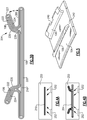
- internal cooling circuits 408 are shown at both forward and aft ends of the BOAS 400.
- Inlets 414 and outlets 416 to circuits 408 are shown.
- Forming such a BOAS would be difficult utilizing known methods for forming laminated components.
- the teachings of this disclosure may extend to other gas turbine engine components.
- FIG 8A shows the BOAS 400 having the hook portions 402 and 404.
- the circuit 408 is shown interconnecting an inlet 414 and an outlet 416.
- the cooling airflow is generally in an axial direction in this disclosed embodiment and from a point intermediate hook 402 and 404, and to a location outward of hooks 402/404.
- the cooling circuits 408 are shown in phantom and have a relatively complex shape. The shape will be described in more detail below. To form such a product, a method will now be disclosed.
- Figure 9A shows an initial formed intermediate product (or "intermediate portion") 420 as an initial method step. This is not unlike the concept described above wherein an intermediate series of laminations is initially prepared.
- these laminates or plies are layered together as shown at step 422. Then, they are densified at step 424 and as described in more detail above.
- FIG 10A shows a subsequent method step.
- an ultrasonic machine 430 ultrasonically forms circuit channels 428 into the outer layer or outer layers of the intermediate structure 420.
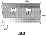
- an intermediate product after the Figure 10A step has circuits with an outlet end 440 and inlet end which extends in a generally triangular cross-section 442.
- intermediate circuits 428 can thus be formed in any number of complex shapes and sizes utilizing modern ultrasonic methods. However, it should be understood that other manufacturing techniques may be utilized to form the circuits in this intermediate product.
- outer layers 454 and inner layers 452 are placed around the intermediate internal layer 426. This is shown at step 450.
- this intermediate product 450 is then densified at step 460.
- the final circuits 408 remain.
- Figure 12B shows a subsequent method step wherein the ultrasonic machine 430 now forms the holes 414 and 416 through the radially outer layer or layers 454.
- the shape dimension and other aspects of the cooling circuit, as well as the number of cooling circuits, can be determined to achieve desired cooling properties once the overall conditions to be faced by the BOAS are known.
- a method of forming a gas turbine engine component could be said to include the steps of: (a) forming an intermediate portion; (b) forming cooling circuit structure into at least an outer layer of the intermediate portion; (c) providing an outer layer over the formed cooling circuits to close off the cooling circuits, such that there are laminate on both a radially inner and a radially outer side of the cooling circuits; and (d) forming an inlet and an outlet to the cooling circuits.
- the BOAS are also formed to have a circumferential arc about the axis Z, such that even when not mounted in a gas turbine engine, there is a radially inner and a radially outer side to the BOAS.
Landscapes
- Engineering & Computer Science (AREA)
- Chemical & Material Sciences (AREA)
- Mechanical Engineering (AREA)
- General Engineering & Computer Science (AREA)
- Ceramic Engineering (AREA)
- Materials Engineering (AREA)
- Manufacturing & Machinery (AREA)
- Inorganic Chemistry (AREA)
- Structural Engineering (AREA)
- Organic Chemistry (AREA)
- Turbine Rotor Nozzle Sealing (AREA)
- Structures Of Non-Positive Displacement Pumps (AREA)
Abstract
Description
- This application relates to a method and apparatus, for forming a gas turbine engine component from laminate, but having internal cooling circuits.
- Gas turbine engines are known and typically include a compressor compressing air and delivering it into a combustor. The air is mixed with fuel in the combustor and ignited. Products of the combustion pass downstream over turbine rotors, driving them to rotate.
- It is desirable to ensure that the bulk of the products of combustion pass over turbine blades on the turbine rotor. As such, it is known to provide blade outer air seals radially outwardly of the blades.
- Blade outer air seals have been proposed made of ceramic matrix composite fiber layers.
- In an aspect of the present invention, a method of forming a gas turbine engine component includes the steps of (a) forming an intermediate portion, (b) forming cooling circuit structure into at least an outer layer of the intermediate portion, (c) providing an outer layer over the formed cooling circuits to close off the cooling circuits, such that there are laminate on both a radially inner and a radially outer side of the cooling circuits, and (d) forming an inlet and an outlet to the cooling circuits through the outer layer.
- In an embodiment according to the previous embodiment, the component is a blade outer air seal.
- In another embodiment according to any of the previous embodiments, the intermediate portion includes a plurality of laminate.
- In another embodiment according to any of the previous embodiments, at least one inner layer is also added inward of the intermediate portion in step (c).
- In another embodiment according to any of the previous embodiments, an overwrap layer provides both the inner and outer layer.
- In another embodiment according to any of the previous embodiments, the intermediate portion and the layers are formed of a ceramic matrix composite.
- In another embodiment according to any of the previous embodiments, step (b) is performed by an ultrasonic machine.
- In another embodiment according to any of the previous embodiments, step (d) is performed by an ultrasonic machine.
- In another embodiment according to any of the previous embodiments, there are a plurality of separate cooling circuits formed within the intermediate layer.
- In another embodiment according to any of the previous embodiments, there is an individual inlet and an individual outlet for each of the plurality of cooling circuits.
- In another embodiment according to any of the previous embodiments, the cooling circuit has a non-rectangular shape.
- In another aspect of the present invention, a gas turbine engine includes a compressor section and a turbine section. The turbine section includes at least one rotor and at least one blade extending radially outwardly from the rotor to a radially outer tip. A blade outer air seal assembly is positioned radially outwardly of the radially outer tip of the blade. The blade outer air seal has forward and aft hooks. The forward and aft hooks are supported on forward and aft seal hooks of an attachment. The blade outer air seal is formed of a plurality of laminate layered with a central web formed of a plurality of laminate members including an inner reinforcement member, and an outer overwrap that wraps around the inner reinforcement member. The blade outer air seal forward of a plurality of laminate layers, with internal cooling circuits formed in one of the layers, with at least one other layer radially outward of the at least one layer, and closing off the internal cooling circuit.
- These and other features may be best understood from the following drawings and specification.
-
-
Figure 1 schematically shows a gas turbine engine. -
Figure 2 shows a turbine section that may be part of theFigure 1 engine. -
Figure 3A is a cross-sectional view through a blade outer air seal. -
Figure 3B shows an alternative blade outer air seal. -
Figure 4A shows a first method step to form a blade outer air seal. -
Figure 4B shows a subsequent step to form a blade outer air seal. -
Figure 5 shows another embodiment of a blade outer air seal. -
Figure 6 shows an alternative embodiment blade outer air seal. -
Figure 7 shows a blade outer air seal according to this disclosure. -
Figure 8A is a perspective view of theFigure 7 blade outer air seal. -
Figure 8B shows some internal structure of theFigure 8A blade outer air seal. -
Figure 9A shows a first method step to form theFigure 8A/8B blade outer air seal. -
Figure 9B shows a subsequent method step to form theFigure 8A/8B blade outer air seal. -
Figure 10A shows a subsequent method step to form theFigure 8A/8B blade outer air seal. -
Figure 10B shows detail of an intermediate product for forming theFigure 8A/8B blade outer air seal. -
Figure 11 shows a subsequent step to form theFigure 8A/8B blade outer air seal. -
Figure 12A shows a subsequent step to form theFigure 8A/8B blade outer air seal. -
Figure 12B shows a final step to form theFigure 8A/8B blade outer air seal. -
Figure 12C shows a final blade outer air seal, partially in phantom. -
Figure 1 schematically illustrates agas turbine engine 20. Thegas turbine engine 20 is disclosed herein as a two-spool turbofan that generally incorporates afan section 22, acompressor section 24, a combustor section 26 and aturbine section 28. Thefan section 22 drives air along a bypass flow path B in a bypass duct defined within anacelle 15, and also drives air along a core flow path C for compression and communication into the combustor section 26 then expansion through theturbine section 28. Although depicted as a two-spool turbofan gas turbine engine in the disclosed non-limiting embodiment, it should be understood that the concepts described herein are not limited to use with two-spool turbofans as the teachings may be applied to other types of turbine engines including three-spool architectures. - The
exemplary engine 20 generally includes alow speed spool 30 and ahigh speed spool 32 mounted for rotation about an engine central longitudinal axis A relative to an enginestatic structure 36 viaseveral bearing systems 38. It should be understood thatvarious bearing systems 38 at various locations may alternatively or additionally be provided, and the location ofbearing systems 38 may be varied as appropriate to the application. - The
low speed spool 30 generally includes aninner shaft 40 that interconnects, a first (or low)pressure compressor 44 and a first (or low)pressure turbine 46. Theinner shaft 40 is connected to thefan 42 through a speed change mechanism, which in exemplarygas turbine engine 20 is illustrated as a gearedarchitecture 48 to drive afan 42 at a lower speed than thelow speed spool 30. Thehigh speed spool 32 includes anouter shaft 50 that interconnects a second (or high)pressure compressor 52 and a second (or high)pressure turbine 54. Acombustor 56 is arranged inexemplary gas turbine 20 between thehigh pressure compressor 52 and thehigh pressure turbine 54. Amid-turbine frame 57 of the enginestatic structure 36 may be arranged generally between thehigh pressure turbine 54 and thelow pressure turbine 46. Themid-turbine frame 57 further supports bearingsystems 38 in theturbine section 28. Theinner shaft 40 and theouter shaft 50 are concentric and rotate viabearing systems 38 about the engine central longitudinal axis A which is collinear with their longitudinal axes. - The core airflow is compressed by the
low pressure compressor 44 then thehigh pressure compressor 52, mixed and burned with fuel in thecombustor 56, then expanded over thehigh pressure turbine 54 andlow pressure turbine 46. Themid-turbine frame 57 includesairfoils 59 which are in the core airflow path C. Theturbines low speed spool 30 andhigh speed spool 32 in response to the expansion. It will be appreciated that each of the positions of thefan section 22,compressor section 24, combustor section 26,turbine section 28, and fandrive gear system 48 may be varied. For example,gear system 48 may be located aft of the low pressure compressor, or aft of the combustor section 26 or even aft ofturbine section 28, andfan 42 may be positioned forward or aft of the location ofgear system 48. - The
engine 20 in one example is a high-bypass geared aircraft engine. In a further example, theengine 20 bypass ratio is greater than about six, with an example embodiment being greater than about ten, the gearedarchitecture 48 is an epicyclic gear train, such as a planetary gear system or other gear system, with a gear reduction ratio of greater than about 2.3 and thelow pressure turbine 46 has a pressure ratio that is greater than about five. In one disclosed embodiment, theengine 20 bypass ratio is greater than about ten, the fan diameter is significantly larger than that of thelow pressure compressor 44, and thelow pressure turbine 46 has a pressure ratio that is greater than about five.Low pressure turbine 46 pressure ratio is pressure measured prior to inlet oflow pressure turbine 46 as related to the pressure at the outlet of thelow pressure turbine 46 prior to an exhaust nozzle. The gearedarchitecture 48 may be an epicycle gear train, such as a planetary gear system or other gear system, with a gear reduction ratio of greater than about 2.3:1 and less than about 5:1. It should be understood, however, that the above parameters are only exemplary of one embodiment of a geared architecture engine and that the present invention is applicable to other gas turbine engines including direct drive turbofans. - A significant amount of thrust is provided by the bypass flow B due to the high bypass ratio. The
fan section 22 of theengine 20 is designed for a particular flight condition -- typically cruise at about 0.8 Mach and about 35,000 feet (10,668 meters). The flight condition of 0.8 Mach and 35,000 ft (10,668 meters), with the engine at its best fuel consumption - also known as "bucket cruise Thrust Specific Fuel Consumption ('TSFC')" - is the industry standard parameter of lbm of fuel being burned divided by lbf of thrust the engine produces at that minimum point. "Low fan pressure ratio" is the pressure ratio across the fan blade alone, without a Fan Exit Guide Vane ("FEGV") system. The low fan pressure ratio as disclosed herein according to one non-limiting embodiment is less than about 1.45. "Low corrected fan tip speed" is the actual fan tip speed in ft/sec divided by an industry standard temperature correction of [(Tram °R) / (518.7 °R)]0.5 (where °R = K x 9/5). The "Low corrected fan tip speed" as disclosed herein according to one non-limiting embodiment is less than about 1150 ft / second (350.5 meters/second). -
Figure 2 shows aturbine section 100, which may be incorporated into a gas turbine engine such as the one shown inFigure 1 . However, it should be understood that theturbine section 100 could be utilized in other gas turbine engines, and even gas turbine engines not having a fan section at all. - A
turbine blade 102 has a radiallyouter tip 103 that is spaced from a blade outer air seal ("BOAS") 104. The BOAS may be formed of a ceramic matrix composite ("CMC") or a monolithic ceramic material. Aforward hook 106 and anaft hook 108 are formed on theBOAS 104. Asupport block 110 includes a rearwardly facing forward hook 112 supporting forward hook 106 and a forwardly facingaft hook 114 supportingaft hook 108. - As shown, the
attachment block 110 is supported on a static support orengine case 117.Case 117 has a rearwardly facing forward hook 118 supporting forwardly facing forward hook 116 of theattachment block 110. Thecase 117 has a rearwardly facingaft hook 122 supporting a forwardly facingaft hook 120 on the attachment block.Case 117 may extend for a full 360° about a rotational axis Z ofblade 102. - It should be understood that the arrangement of the
hooks hooks hooks - A
wedge seal 124 can also be seen. A circled detail is shown, wherein thewedge seal 124 can be seen to span acircumferential gap 600 to seal between circumferentiallyadjacent BOAS surface 599 circumferentially outward of hooks 106 (hooks 108 would look the same) that support thewedge seal 124. -
Figure 3A shows theBOAS 104 havinghooks central web 109. - The
BOAS 104 is formed of a ceramic matrix composite ("CMC") material. The BOAS is formed of a plurality of CMC laminates. The laminates may be silicon carbide fibers, formed into a woven fabric in each layer. The fibers may be coated by a boron nitride. - Generally in the prior art there have been only a few laminate in a
central web 109. In thisembodiment BOAS 104 is shown to have acentral reinforcement laminate 150 including a plurality of layers. Anoverwrap 152 also includes a plurality of layers or laminates, and spans acentral web 109 which is defined axially betweenhooks overwrap layer 152 also extends back to form a radially inner portion of thehooks hook backing portion 154 is secured to theoverwrap portion 152 to complete thehooks Spaces -
Figure 3B shows aBOAS embodiment 204. As shown, there arecentral reinforcement laminate 210 and outer overwrap plies 220. There are hook reinforcement plies 222 extending across theweb 109 and into each of the hook areas. There are also inner front end aft plies 224 forming radially inner portions of thehooks - Each of
structures 150/152/154/210/220/224 and 224 are shown to include plural layers or laminates. - The use of several laminates in the
web 109 provides benefits. However, it is generally desirable to add additional material to make the laminates more stiff than their free woven fiber state. Thus, a process known as densification is utilized to increase the density of the laminate material after assembly. If too many laminate are formed in the central web, the radially more central laminate may not be adequately densified. - Thus, in a method step as shown in
Figure 4A the reinforcement plies inmember 210 may be initially stiffened in adensification chamber 250 as a separate densification process.Injectors 252 are schematically shown which inject materials such, as a silicon carbide matrix material, into spaces between the fibers in the woven layers. This may be utilized in theFigure 4A step to provide 100% of the desired densification, or only some percentage. As an example, this initial step may be utilized to form between 10 and 90% of a desired densification. - One hundred percent densification may be defined as the layers being completely saturated with the matrix and about the fibers. Complete saturation may be difficult to achieve in practice.
- As shown in
Figure 4B , theentire BOAS 204 is then formed with the additional layers, and having the overwrap plies 220 wrapping over thehook portions 222/224 and thereinforcement portion 210, and then additional densification occurs to all of these areas. - In another method, the
Figure 4A step could be eliminated, and the entire densification process occur in a single step. That is, rather than forcingmember 210 as an intermediate product and then performing theFigure 4B steps about thisintermediate product 210, the entire BOAS can be formed at one time with the steps ofFigure 4B . - The same
Figure 4A/4B process may be useful for theFigure 3A BOAS. - Returning to
Figures 3A and3B ,spaces 158/156 and 228 between the laminates may be filled with loose fibers, and in the densification process these will also be filled to harden. - In addition, it can be seen that the
hooks Figure 2 ). Rather, the angle A is at some intermediate angle between 20 and 70 degrees relative to anupper surface 300 of the BOAS, and radially inward of the hook. - In embodiments the angle A may be between 20 and 70 degrees.
Outer surface 226 ofhooks 106/108 are curved, not sharp cornered. This positioning facilitates the assembly of the BOAS, as will be explained below. -
Figure 5 showsBOAS 104 havinghooks 106 with 108 and anotch 240 that will catch on a tab on an attachment block to resist rotation. -
BOAS 300 as shown inFigure 6 has itshooks edges 312. Thereinforcement layer 310 is shown in this figure. - BOAS formed according to this disclosure provide beneficial operation due to the additional stiffness from the reinforcement layer. Options such as the pre-densification of
Figure 4A ensure that the central web will be of a desired rigidity, which might not occur if the inner layers were not adequately densified. - A method of forming a blade outer air seal could be said to include the steps providing an inner reinforcement member formed of a plurality of layers fibrous woven structure. A densification material is injected into the fibrous woven structure and about fibers within the fibrous woven structure. Outer overwrap layers are wrapped around the inner reinforcement member. A densification matrix about fibers is injected in the fibrous woven overwrap structure.
- A BOAS and method as described above is disclosed and claimed in copending
U.S. Patent Application Serial No. 16/055,636, filed August 6, 2018 and entitled "Blade Outer Air Seal Reinforcement Laminate." - As can be appreciated, items formed of CMC laminate have beneficial characteristics, and the methods described above provide powerful design options for forming such components. However, there are challenges with incorporating certain structures that would be desirable in gas turbine engine components into these laminate based structures.
-
Figure 7 shows aBOAS 400 which may be formed of laminate and generally as utilizing methods described above. Thehook portion 402 and thehook portion 404 are shown as well as acentral web 406. However,internal cooling circuits 408 are shown at both forward and aft ends of theBOAS 400.Inlets 414 andoutlets 416 tocircuits 408 are shown. As shown, there is an overlap laminate and such that there are laminate 410 radially inward of the coolingcircuits 408 and at least onelaminate 412 radially outward of the coolingcircuits 408. Forming such a BOAS would be difficult utilizing known methods for forming laminated components. Notably, while a BOAS, in particular, is described, the teachings of this disclosure may extend to other gas turbine engine components. -
Figure 8A shows theBOAS 400 having thehook portions circuit 408 is shown interconnecting aninlet 414 and anoutlet 416. The cooling airflow is generally in an axial direction in this disclosed embodiment and from a pointintermediate hook hooks 402/404. - As shown in
Figure 8B , the coolingcircuits 408 are shown in phantom and have a relatively complex shape. The shape will be described in more detail below. To form such a product, a method will now be disclosed. -
Figure 9A shows an initial formed intermediate product (or "intermediate portion") 420 as an initial method step. This is not unlike the concept described above wherein an intermediate series of laminations is initially prepared. - As shown in
Figure 9B , these laminates or plies are layered together as shown atstep 422. Then, they are densified atstep 424 and as described in more detail above. -
Figure 10A shows a subsequent method step. In thisstep 426, anultrasonic machine 430 ultrasonicallyforms circuit channels 428 into the outer layer or outer layers of theintermediate structure 420. As shown inFigure 10B , an intermediate product after theFigure 10A step has circuits with anoutlet end 440 and inlet end which extends in a generallytriangular cross-section 442. - These
intermediate circuits 428 can thus be formed in any number of complex shapes and sizes utilizing modern ultrasonic methods. However, it should be understood that other manufacturing techniques may be utilized to form the circuits in this intermediate product. - In
Figure 11 , in a subsequent stepouter layers 454 andinner layers 452 are placed around the intermediateinternal layer 426. This is shown atstep 450. - While
separate layers intermediate circuits 428 are thus enclosed in this step. - As shown in
Figure 12A , in a subsequent method step thisintermediate product 450 is then densified atstep 460. Thefinal circuits 408 remain. -
Figure 12B shows a subsequent method step wherein theultrasonic machine 430 now forms theholes - Finally, as shown in
Figure 12C , thefinal component 400 remains. - The shape dimension and other aspects of the cooling circuit, as well as the number of cooling circuits, can be determined to achieve desired cooling properties once the overall conditions to be faced by the BOAS are known.
- A method of forming a gas turbine engine component could be said to include the steps of: (a) forming an intermediate portion; (b) forming cooling circuit structure into at least an outer layer of the intermediate portion; (c) providing an outer layer over the formed cooling circuits to close off the cooling circuits, such that there are laminate on both a radially inner and a radially outer side of the cooling circuits; and (d) forming an inlet and an outlet to the cooling circuits.
- As may be known, the BOAS are also formed to have a circumferential arc about the axis Z, such that even when not mounted in a gas turbine engine, there is a radially inner and a radially outer side to the BOAS.
- Although a method and component embodiment of this invention has been disclosed, a worker of ordinary skill in this art would recognize that certain modifications would come within the scope of this disclosure. For that reason, the following claims should be studied to determine the true scope and content of this disclosure.
Claims (12)
- A method of forming a gas turbine engine component (400) comprising the steps of:(a) forming an intermediate portion (420);(b) forming cooling circuit (408) structure into at least an outer layer of said intermediate portion (420);(c) providing an outer layer (454) over said formed cooling circuits (408) to close off said cooling circuits (408), such that there are laminates on both a radially inner and a radially outer side of said cooling circuits (408); and(d) forming an inlet (414) and an outlet (416) to said cooling circuits (408) through said outer layer (454).
- The method as set forth in claim 1, wherein said component is a blade outer air seal (400).
- The method as set forth in claim 1 or 2, wherein said intermediate portion (420) includes a plurality of laminates.
- The method as set forth in any preceding claim, wherein at least one inner layer (452) is also added inward of said intermediate portion (420) in step (c).
- The method as set forth in claim 4, wherein an overwrap layer provides both said inner and outer layer (452, 454).
- The method as set forth in any preceding claim, wherein said intermediate portion (420) and said layer or layers (452, 454) are formed of a ceramic matrix composite.
- The method as set forth in any preceding claim, wherein step (b) is performed by an ultrasonic machine (430).
- The method as set forth in any preceding claim, wherein step (d) is performed by an ultrasonic machine (430).
- The method as set forth in any preceding claim, wherein there are a plurality of separate cooling circuits (408) formed within said intermediate portion (420).
- The method as set forth in claim 9, wherein there is an individual inlet (414) and an individual outlet (416) for each of said plurality of cooling circuits (408).
- The method as set forth in any preceding claim, wherein said cooling circuit (408) has a non-rectangular shape.
- A gas turbine engine (20) comprising:a compressor section (24) and a turbine section (28, 100), said turbine section (28, 100) including at least one rotor and at least one blade (102) extending radially outwardly from said rotor to a radially outer tip (103); anda blade outer air seal assembly positioned radially outwardly of said radially outer tip (103) of said blade (102), said blade outer air seal (400) having forward and aft hooks (402, 404), and said forward and aft hooks (402, 404) being supported on forward and aft seal hooks (112, 114) of an attachment (110), wherein:said blade outer air seal (400) is formed of a plurality of laminates layered with a central web (406) formed of a plurality of laminate members including an inner reinforcement member, and an outer overwrap that wraps around said inner reinforcement member; andsaid blade outer air seal (400) formed of a plurality of laminate layers, with internal cooling circuits (408) formed in one of said layers, with at least one other layer (454) radially outward of said at least one layer, and closing off said internal cooling circuit (408).
Priority Applications (1)
| Application Number | Priority Date | Filing Date | Title |
|---|---|---|---|
| EP23182894.8A EP4234892A3 (en) | 2018-08-29 | 2019-08-29 | Method of forming a gas turbine component formed of laminate |
Applications Claiming Priority (1)
| Application Number | Priority Date | Filing Date | Title |
|---|---|---|---|
| US16/116,140 US10822985B2 (en) | 2018-08-29 | 2018-08-29 | Internal cooling circuit for blade outer air seal formed of laminate |
Related Child Applications (2)
| Application Number | Title | Priority Date | Filing Date |
|---|---|---|---|
| EP23182894.8A Division-Into EP4234892A3 (en) | 2018-08-29 | 2019-08-29 | Method of forming a gas turbine component formed of laminate |
| EP23182894.8A Division EP4234892A3 (en) | 2018-08-29 | 2019-08-29 | Method of forming a gas turbine component formed of laminate |
Publications (3)
| Publication Number | Publication Date |
|---|---|
| EP3617459A2 true EP3617459A2 (en) | 2020-03-04 |
| EP3617459A3 EP3617459A3 (en) | 2020-07-29 |
| EP3617459B1 EP3617459B1 (en) | 2023-09-27 |
Family
ID=67809385
Family Applications (2)
| Application Number | Title | Priority Date | Filing Date |
|---|---|---|---|
| EP19194470.1A Active EP3617459B1 (en) | 2018-08-29 | 2019-08-29 | Method of forming a gas turbine component formed of laminate |
| EP23182894.8A Pending EP4234892A3 (en) | 2018-08-29 | 2019-08-29 | Method of forming a gas turbine component formed of laminate |
Family Applications After (1)
| Application Number | Title | Priority Date | Filing Date |
|---|---|---|---|
| EP23182894.8A Pending EP4234892A3 (en) | 2018-08-29 | 2019-08-29 | Method of forming a gas turbine component formed of laminate |
Country Status (2)
| Country | Link |
|---|---|
| US (1) | US10822985B2 (en) |
| EP (2) | EP3617459B1 (en) |
Families Citing this family (5)
| Publication number | Priority date | Publication date | Assignee | Title |
|---|---|---|---|---|
| FR3095668B1 (en) * | 2019-05-03 | 2021-04-09 | Safran Aircraft Engines | Spacer-mounted turbine ring assembly |
| US12044132B1 (en) * | 2023-05-09 | 2024-07-23 | Rtx Corporation | Seal arc segment with CMC ply cutouts for cooling channels |
| US12435640B2 (en) | 2023-11-02 | 2025-10-07 | Rtx Corporation | Gas turbine engine vane outer diameter platform integrated with blade outer air seal |
| US12584418B2 (en) * | 2024-08-15 | 2026-03-24 | Rtx Corporation | CMC component with cooling cavity |
| US20260049559A1 (en) * | 2024-08-15 | 2026-02-19 | Rtx Corporation | Cmc component with cooling cavity |
Family Cites Families (13)
| Publication number | Priority date | Publication date | Assignee | Title |
|---|---|---|---|---|
| US6905302B2 (en) | 2003-09-17 | 2005-06-14 | General Electric Company | Network cooled coated wall |
| US7670108B2 (en) * | 2006-11-21 | 2010-03-02 | Siemens Energy, Inc. | Air seal unit adapted to be positioned adjacent blade structure in a gas turbine |
| US7597533B1 (en) * | 2007-01-26 | 2009-10-06 | Florida Turbine Technologies, Inc. | BOAS with multi-metering diffusion cooling |
| US7704039B1 (en) * | 2007-03-21 | 2010-04-27 | Florida Turbine Technologies, Inc. | BOAS with multiple trenched film cooling slots |
| US7988410B1 (en) * | 2007-11-19 | 2011-08-02 | Florida Turbine Technologies, Inc. | Blade tip shroud with circular grooves |
| US8177492B2 (en) * | 2008-03-04 | 2012-05-15 | United Technologies Corporation | Passage obstruction for improved inlet coolant filling |
| US9151179B2 (en) * | 2011-04-13 | 2015-10-06 | General Electric Company | Turbine shroud segment cooling system and method |
| GB201308605D0 (en) * | 2013-05-14 | 2013-06-19 | Rolls Royce Plc | A shroud arrangement for a gas turbine engine |
| US9752440B2 (en) * | 2015-05-29 | 2017-09-05 | General Electric Company | Turbine component having surface cooling channels and method of forming same |
| US10465533B2 (en) | 2015-10-08 | 2019-11-05 | General Electric Company | Ceramic matrix composite component and process of producing a ceramic matrix composite component |
| US10309252B2 (en) | 2015-12-16 | 2019-06-04 | General Electric Company | System and method for cooling turbine shroud trailing edge |
| US10677079B2 (en) | 2016-11-17 | 2020-06-09 | Raytheon Technologies Corporation | Airfoil with ceramic airfoil piece having internal cooling circuit |
| US20180223681A1 (en) | 2017-02-09 | 2018-08-09 | General Electric Company | Turbine engine shroud with near wall cooling |
-
2018
- 2018-08-29 US US16/116,140 patent/US10822985B2/en active Active
-
2019
- 2019-08-29 EP EP19194470.1A patent/EP3617459B1/en active Active
- 2019-08-29 EP EP23182894.8A patent/EP4234892A3/en active Pending
Also Published As
| Publication number | Publication date |
|---|---|
| EP3617459B1 (en) | 2023-09-27 |
| US10822985B2 (en) | 2020-11-03 |
| US20200072069A1 (en) | 2020-03-05 |
| EP4234892A3 (en) | 2023-10-04 |
| EP3617459A3 (en) | 2020-07-29 |
| EP4234892A2 (en) | 2023-08-30 |
Similar Documents
| Publication | Publication Date | Title |
|---|---|---|
| US11105215B2 (en) | Feather seal slot arrangement for a CMC BOAS assembly | |
| EP3617459B1 (en) | Method of forming a gas turbine component formed of laminate | |
| EP3613951B1 (en) | Blade outer air seal with circumferential hook assembly | |
| US10927710B2 (en) | Blade outer air seal laminate T-joint | |
| EP3626934A1 (en) | Turbine section comprising a featherseal formed of cmc material | |
| EP3663533B1 (en) | Method of forming a boas | |
| EP3767075A1 (en) | Assembly with blade outer air seal formed of ceramic matrix composite | |
| EP3767076A1 (en) | Assembly with blade outer air seal formed of ceramic matrix composite | |
| EP3608514A1 (en) | Structural support for blade outer air seal assembly | |
| EP3608513B1 (en) | Blade outer air seal reinforcement laminate | |
| EP3767077B1 (en) | Cmc boas arrangement | |
| US11242991B2 (en) | CMC component arrangement and method of manufacture | |
| US11286801B2 (en) | Boas with twin axial dovetail | |
| US11098608B2 (en) | CMC BOAS with internal support structure | |
| EP3712383A1 (en) | Cmc blade outer air seal |
Legal Events
| Date | Code | Title | Description |
|---|---|---|---|
| PUAI | Public reference made under article 153(3) epc to a published international application that has entered the european phase |
Free format text: ORIGINAL CODE: 0009012 |
|
| STAA | Information on the status of an ep patent application or granted ep patent |
Free format text: STATUS: THE APPLICATION HAS BEEN PUBLISHED |
|
| AK | Designated contracting states |
Kind code of ref document: A2 Designated state(s): AL AT BE BG CH CY CZ DE DK EE ES FI FR GB GR HR HU IE IS IT LI LT LU LV MC MK MT NL NO PL PT RO RS SE SI SK SM TR |
|
| AX | Request for extension of the european patent |
Extension state: BA ME |
|
| RIN1 | Information on inventor provided before grant (corrected) |
Inventor name: CLARK, THOMAS E. Inventor name: BARKER, WILLIAM M. Inventor name: SMIDDY, WINSTON GREGORY Inventor name: WHITNEY, DANIEL J. |
|
| PUAL | Search report despatched |
Free format text: ORIGINAL CODE: 0009013 |
|
| AK | Designated contracting states |
Kind code of ref document: A3 Designated state(s): AL AT BE BG CH CY CZ DE DK EE ES FI FR GB GR HR HU IE IS IT LI LT LU LV MC MK MT NL NO PL PT RO RS SE SI SK SM TR |
|
| AX | Request for extension of the european patent |
Extension state: BA ME |
|
| RIC1 | Information provided on ipc code assigned before grant |
Ipc: F01D 25/00 20060101ALI20200623BHEP Ipc: F01D 25/12 20060101ALI20200623BHEP Ipc: F01D 25/24 20060101ALN20200623BHEP Ipc: F01D 11/24 20060101AFI20200623BHEP |
|
| STAA | Information on the status of an ep patent application or granted ep patent |
Free format text: STATUS: REQUEST FOR EXAMINATION WAS MADE |
|
| 17P | Request for examination filed |
Effective date: 20210129 |
|
| RBV | Designated contracting states (corrected) |
Designated state(s): AL AT BE BG CH CY CZ DE DK EE ES FI FR GB GR HR HU IE IS IT LI LT LU LV MC MK MT NL NO PL PT RO RS SE SI SK SM TR |
|
| RAP1 | Party data changed (applicant data changed or rights of an application transferred) |
Owner name: RAYTHEON TECHNOLOGIES CORPORATION |
|
| STAA | Information on the status of an ep patent application or granted ep patent |
Free format text: STATUS: EXAMINATION IS IN PROGRESS |
|
| 17Q | First examination report despatched |
Effective date: 20211006 |
|
| GRAP | Despatch of communication of intention to grant a patent |
Free format text: ORIGINAL CODE: EPIDOSNIGR1 |
|
| STAA | Information on the status of an ep patent application or granted ep patent |
Free format text: STATUS: GRANT OF PATENT IS INTENDED |
|
| RIC1 | Information provided on ipc code assigned before grant |
Ipc: F01D 25/24 20060101ALN20230217BHEP Ipc: F01D 25/12 20060101ALI20230217BHEP Ipc: F01D 25/00 20060101ALI20230217BHEP Ipc: F01D 11/24 20060101AFI20230217BHEP |
|
| INTG | Intention to grant announced |
Effective date: 20230316 |
|
| GRAS | Grant fee paid |
Free format text: ORIGINAL CODE: EPIDOSNIGR3 |
|
| GRAA | (expected) grant |
Free format text: ORIGINAL CODE: 0009210 |
|
| STAA | Information on the status of an ep patent application or granted ep patent |
Free format text: STATUS: THE PATENT HAS BEEN GRANTED |
|
| AK | Designated contracting states |
Kind code of ref document: B1 Designated state(s): AL AT BE BG CH CY CZ DE DK EE ES FI FR GB GR HR HU IE IS IT LI LT LU LV MC MK MT NL NO PL PT RO RS SE SI SK SM TR |
|
| REG | Reference to a national code |
Ref country code: GB Ref legal event code: FG4D |
|
| REG | Reference to a national code |
Ref country code: CH Ref legal event code: EP |
|
| REG | Reference to a national code |
Ref country code: DE Ref legal event code: R096 Ref document number: 602019038094 Country of ref document: DE |
|
| REG | Reference to a national code |
Ref country code: IE Ref legal event code: FG4D |
|
| RAP4 | Party data changed (patent owner data changed or rights of a patent transferred) |
Owner name: RTX CORPORATION |
|
| REG | Reference to a national code |
Ref country code: LT Ref legal event code: MG9D |
|
| PG25 | Lapsed in a contracting state [announced via postgrant information from national office to epo] |
Ref country code: GR Free format text: LAPSE BECAUSE OF FAILURE TO SUBMIT A TRANSLATION OF THE DESCRIPTION OR TO PAY THE FEE WITHIN THE PRESCRIBED TIME-LIMIT Effective date: 20231228 |
|
| PG25 | Lapsed in a contracting state [announced via postgrant information from national office to epo] |
Ref country code: SE Free format text: LAPSE BECAUSE OF FAILURE TO SUBMIT A TRANSLATION OF THE DESCRIPTION OR TO PAY THE FEE WITHIN THE PRESCRIBED TIME-LIMIT Effective date: 20230927 Ref country code: RS Free format text: LAPSE BECAUSE OF FAILURE TO SUBMIT A TRANSLATION OF THE DESCRIPTION OR TO PAY THE FEE WITHIN THE PRESCRIBED TIME-LIMIT Effective date: 20230927 Ref country code: NO Free format text: LAPSE BECAUSE OF FAILURE TO SUBMIT A TRANSLATION OF THE DESCRIPTION OR TO PAY THE FEE WITHIN THE PRESCRIBED TIME-LIMIT Effective date: 20231227 Ref country code: LV Free format text: LAPSE BECAUSE OF FAILURE TO SUBMIT A TRANSLATION OF THE DESCRIPTION OR TO PAY THE FEE WITHIN THE PRESCRIBED TIME-LIMIT Effective date: 20230927 Ref country code: LT Free format text: LAPSE BECAUSE OF FAILURE TO SUBMIT A TRANSLATION OF THE DESCRIPTION OR TO PAY THE FEE WITHIN THE PRESCRIBED TIME-LIMIT Effective date: 20230927 Ref country code: HR Free format text: LAPSE BECAUSE OF FAILURE TO SUBMIT A TRANSLATION OF THE DESCRIPTION OR TO PAY THE FEE WITHIN THE PRESCRIBED TIME-LIMIT Effective date: 20230927 Ref country code: GR Free format text: LAPSE BECAUSE OF FAILURE TO SUBMIT A TRANSLATION OF THE DESCRIPTION OR TO PAY THE FEE WITHIN THE PRESCRIBED TIME-LIMIT Effective date: 20231228 Ref country code: FI Free format text: LAPSE BECAUSE OF FAILURE TO SUBMIT A TRANSLATION OF THE DESCRIPTION OR TO PAY THE FEE WITHIN THE PRESCRIBED TIME-LIMIT Effective date: 20230927 |
|
| REG | Reference to a national code |
Ref country code: NL Ref legal event code: MP Effective date: 20230927 |
|
| REG | Reference to a national code |
Ref country code: AT Ref legal event code: MK05 Ref document number: 1615630 Country of ref document: AT Kind code of ref document: T Effective date: 20230927 |
|
| PG25 | Lapsed in a contracting state [announced via postgrant information from national office to epo] |
Ref country code: NL Free format text: LAPSE BECAUSE OF FAILURE TO SUBMIT A TRANSLATION OF THE DESCRIPTION OR TO PAY THE FEE WITHIN THE PRESCRIBED TIME-LIMIT Effective date: 20230927 |
|
| PG25 | Lapsed in a contracting state [announced via postgrant information from national office to epo] |
Ref country code: IS Free format text: LAPSE BECAUSE OF FAILURE TO SUBMIT A TRANSLATION OF THE DESCRIPTION OR TO PAY THE FEE WITHIN THE PRESCRIBED TIME-LIMIT Effective date: 20240127 |
|
| PG25 | Lapsed in a contracting state [announced via postgrant information from national office to epo] |
Ref country code: AT Free format text: LAPSE BECAUSE OF FAILURE TO SUBMIT A TRANSLATION OF THE DESCRIPTION OR TO PAY THE FEE WITHIN THE PRESCRIBED TIME-LIMIT Effective date: 20230927 |
|
| PG25 | Lapsed in a contracting state [announced via postgrant information from national office to epo] |
Ref country code: ES Free format text: LAPSE BECAUSE OF FAILURE TO SUBMIT A TRANSLATION OF THE DESCRIPTION OR TO PAY THE FEE WITHIN THE PRESCRIBED TIME-LIMIT Effective date: 20230927 |
|
| PG25 | Lapsed in a contracting state [announced via postgrant information from national office to epo] |
Ref country code: SM Free format text: LAPSE BECAUSE OF FAILURE TO SUBMIT A TRANSLATION OF THE DESCRIPTION OR TO PAY THE FEE WITHIN THE PRESCRIBED TIME-LIMIT Effective date: 20230927 Ref country code: RO Free format text: LAPSE BECAUSE OF FAILURE TO SUBMIT A TRANSLATION OF THE DESCRIPTION OR TO PAY THE FEE WITHIN THE PRESCRIBED TIME-LIMIT Effective date: 20230927 Ref country code: IS Free format text: LAPSE BECAUSE OF FAILURE TO SUBMIT A TRANSLATION OF THE DESCRIPTION OR TO PAY THE FEE WITHIN THE PRESCRIBED TIME-LIMIT Effective date: 20240127 Ref country code: ES Free format text: LAPSE BECAUSE OF FAILURE TO SUBMIT A TRANSLATION OF THE DESCRIPTION OR TO PAY THE FEE WITHIN THE PRESCRIBED TIME-LIMIT Effective date: 20230927 Ref country code: EE Free format text: LAPSE BECAUSE OF FAILURE TO SUBMIT A TRANSLATION OF THE DESCRIPTION OR TO PAY THE FEE WITHIN THE PRESCRIBED TIME-LIMIT Effective date: 20230927 Ref country code: CZ Free format text: LAPSE BECAUSE OF FAILURE TO SUBMIT A TRANSLATION OF THE DESCRIPTION OR TO PAY THE FEE WITHIN THE PRESCRIBED TIME-LIMIT Effective date: 20230927 Ref country code: AT Free format text: LAPSE BECAUSE OF FAILURE TO SUBMIT A TRANSLATION OF THE DESCRIPTION OR TO PAY THE FEE WITHIN THE PRESCRIBED TIME-LIMIT Effective date: 20230927 Ref country code: PT Free format text: LAPSE BECAUSE OF FAILURE TO SUBMIT A TRANSLATION OF THE DESCRIPTION OR TO PAY THE FEE WITHIN THE PRESCRIBED TIME-LIMIT Effective date: 20240129 Ref country code: SK Free format text: LAPSE BECAUSE OF FAILURE TO SUBMIT A TRANSLATION OF THE DESCRIPTION OR TO PAY THE FEE WITHIN THE PRESCRIBED TIME-LIMIT Effective date: 20230927 |
|
| PG25 | Lapsed in a contracting state [announced via postgrant information from national office to epo] |
Ref country code: PL Free format text: LAPSE BECAUSE OF FAILURE TO SUBMIT A TRANSLATION OF THE DESCRIPTION OR TO PAY THE FEE WITHIN THE PRESCRIBED TIME-LIMIT Effective date: 20230927 Ref country code: IT Free format text: LAPSE BECAUSE OF FAILURE TO SUBMIT A TRANSLATION OF THE DESCRIPTION OR TO PAY THE FEE WITHIN THE PRESCRIBED TIME-LIMIT Effective date: 20230927 |
|
| REG | Reference to a national code |
Ref country code: DE Ref legal event code: R097 Ref document number: 602019038094 Country of ref document: DE |
|
| PG25 | Lapsed in a contracting state [announced via postgrant information from national office to epo] |
Ref country code: DK Free format text: LAPSE BECAUSE OF FAILURE TO SUBMIT A TRANSLATION OF THE DESCRIPTION OR TO PAY THE FEE WITHIN THE PRESCRIBED TIME-LIMIT Effective date: 20230927 |
|
| PG25 | Lapsed in a contracting state [announced via postgrant information from national office to epo] |
Ref country code: DK Free format text: LAPSE BECAUSE OF FAILURE TO SUBMIT A TRANSLATION OF THE DESCRIPTION OR TO PAY THE FEE WITHIN THE PRESCRIBED TIME-LIMIT Effective date: 20230927 |
|
| PLBE | No opposition filed within time limit |
Free format text: ORIGINAL CODE: 0009261 |
|
| STAA | Information on the status of an ep patent application or granted ep patent |
Free format text: STATUS: NO OPPOSITION FILED WITHIN TIME LIMIT |
|
| 26N | No opposition filed |
Effective date: 20240628 |
|
| PG25 | Lapsed in a contracting state [announced via postgrant information from national office to epo] |
Ref country code: SI Free format text: LAPSE BECAUSE OF FAILURE TO SUBMIT A TRANSLATION OF THE DESCRIPTION OR TO PAY THE FEE WITHIN THE PRESCRIBED TIME-LIMIT Effective date: 20230927 |
|
| PG25 | Lapsed in a contracting state [announced via postgrant information from national office to epo] |
Ref country code: SI Free format text: LAPSE BECAUSE OF FAILURE TO SUBMIT A TRANSLATION OF THE DESCRIPTION OR TO PAY THE FEE WITHIN THE PRESCRIBED TIME-LIMIT Effective date: 20230927 |
|
| PG25 | Lapsed in a contracting state [announced via postgrant information from national office to epo] |
Ref country code: BG Free format text: LAPSE BECAUSE OF FAILURE TO SUBMIT A TRANSLATION OF THE DESCRIPTION OR TO PAY THE FEE WITHIN THE PRESCRIBED TIME-LIMIT Effective date: 20230927 |
|
| PG25 | Lapsed in a contracting state [announced via postgrant information from national office to epo] |
Ref country code: BG Free format text: LAPSE BECAUSE OF FAILURE TO SUBMIT A TRANSLATION OF THE DESCRIPTION OR TO PAY THE FEE WITHIN THE PRESCRIBED TIME-LIMIT Effective date: 20230927 |
|
| REG | Reference to a national code |
Ref country code: CH Ref legal event code: PL |
|
| PG25 | Lapsed in a contracting state [announced via postgrant information from national office to epo] |
Ref country code: LU Free format text: LAPSE BECAUSE OF NON-PAYMENT OF DUE FEES Effective date: 20240829 |
|
| PG25 | Lapsed in a contracting state [announced via postgrant information from national office to epo] |
Ref country code: CH Free format text: LAPSE BECAUSE OF NON-PAYMENT OF DUE FEES Effective date: 20240831 Ref country code: MC Free format text: LAPSE BECAUSE OF FAILURE TO SUBMIT A TRANSLATION OF THE DESCRIPTION OR TO PAY THE FEE WITHIN THE PRESCRIBED TIME-LIMIT Effective date: 20230927 |
|
| REG | Reference to a national code |
Ref country code: BE Ref legal event code: MM Effective date: 20240831 |
|
| PG25 | Lapsed in a contracting state [announced via postgrant information from national office to epo] |
Ref country code: BE Free format text: LAPSE BECAUSE OF NON-PAYMENT OF DUE FEES Effective date: 20240831 |
|
| PG25 | Lapsed in a contracting state [announced via postgrant information from national office to epo] |
Ref country code: IE Free format text: LAPSE BECAUSE OF NON-PAYMENT OF DUE FEES Effective date: 20240829 |
|
| REG | Reference to a national code |
Ref country code: DE Ref legal event code: R081 Ref document number: 602019038094 Country of ref document: DE Owner name: RTX CORPORATION (N.D.GES.D. STAATES DELAWARE),, US Free format text: FORMER OWNER: RAYTHEON TECHNOLOGIES CORPORATION, FARMINGTON, CT, US |
|
| PGFP | Annual fee paid to national office [announced via postgrant information from national office to epo] |
Ref country code: DE Payment date: 20250724 Year of fee payment: 7 |
|
| PGFP | Annual fee paid to national office [announced via postgrant information from national office to epo] |
Ref country code: GB Payment date: 20250724 Year of fee payment: 7 |
|
| PGFP | Annual fee paid to national office [announced via postgrant information from national office to epo] |
Ref country code: FR Payment date: 20250723 Year of fee payment: 7 |
|
| P01 | Opt-out of the competence of the unified patent court (upc) registered |
Free format text: CASE NUMBER: UPC_APP_0018917_3617459/2025 Effective date: 20251222 |
|
| PG25 | Lapsed in a contracting state [announced via postgrant information from national office to epo] |
Ref country code: CY Free format text: LAPSE BECAUSE OF FAILURE TO SUBMIT A TRANSLATION OF THE DESCRIPTION OR TO PAY THE FEE WITHIN THE PRESCRIBED TIME-LIMIT; INVALID AB INITIO Effective date: 20190829 |
|
| PG25 | Lapsed in a contracting state [announced via postgrant information from national office to epo] |
Ref country code: HU Free format text: LAPSE BECAUSE OF FAILURE TO SUBMIT A TRANSLATION OF THE DESCRIPTION OR TO PAY THE FEE WITHIN THE PRESCRIBED TIME-LIMIT; INVALID AB INITIO Effective date: 20190829 |