EP3617438A1 - Percussive drill bit with radially extended front face - Google Patents
Percussive drill bit with radially extended front face Download PDFInfo
- Publication number
- EP3617438A1 EP3617438A1 EP18191627.1A EP18191627A EP3617438A1 EP 3617438 A1 EP3617438 A1 EP 3617438A1 EP 18191627 A EP18191627 A EP 18191627A EP 3617438 A1 EP3617438 A1 EP 3617438A1
- Authority
- EP
- European Patent Office
- Prior art keywords
- gauge
- radially
- drill bit
- front face
- face
- Prior art date
- Legal status (The legal status is an assumption and is not a legal conclusion. Google has not performed a legal analysis and makes no representation as to the accuracy of the status listed.)
- Withdrawn
Links
- 239000011435 rock Substances 0.000 claims abstract description 18
- 230000002093 peripheral effect Effects 0.000 claims abstract description 15
- 238000011010 flushing procedure Methods 0.000 description 7
- 239000000463 material Substances 0.000 description 6
- 239000012530 fluid Substances 0.000 description 5
- 238000005553 drilling Methods 0.000 description 4
- 238000000926 separation method Methods 0.000 description 4
- 230000009286 beneficial effect Effects 0.000 description 2
- 230000037361 pathway Effects 0.000 description 2
- 230000035515 penetration Effects 0.000 description 2
- 238000009527 percussion Methods 0.000 description 2
- 230000001154 acute effect Effects 0.000 description 1
- 238000005336 cracking Methods 0.000 description 1
- 239000012634 fragment Substances 0.000 description 1
Images




Classifications
-
- E—FIXED CONSTRUCTIONS
- E21—EARTH OR ROCK DRILLING; MINING
- E21B—EARTH OR ROCK DRILLING; OBTAINING OIL, GAS, WATER, SOLUBLE OR MELTABLE MATERIALS OR A SLURRY OF MINERALS FROM WELLS
- E21B10/00—Drill bits
- E21B10/36—Percussion drill bits
- E21B10/38—Percussion drill bits characterised by conduits or nozzles for drilling fluids
-
- E—FIXED CONSTRUCTIONS
- E21—EARTH OR ROCK DRILLING; MINING
- E21B—EARTH OR ROCK DRILLING; OBTAINING OIL, GAS, WATER, SOLUBLE OR MELTABLE MATERIALS OR A SLURRY OF MINERALS FROM WELLS
- E21B10/00—Drill bits
- E21B10/36—Percussion drill bits
-
- E—FIXED CONSTRUCTIONS
- E21—EARTH OR ROCK DRILLING; MINING
- E21B—EARTH OR ROCK DRILLING; OBTAINING OIL, GAS, WATER, SOLUBLE OR MELTABLE MATERIALS OR A SLURRY OF MINERALS FROM WELLS
- E21B10/00—Drill bits
- E21B10/46—Drill bits characterised by wear resisting parts, e.g. diamond inserts
- E21B10/56—Button-type inserts
Definitions
- the present invention relates to a rock drill bit and in particular, although not exclusively, to a percussion rock drill bit having a head with a plurality of forward facing front cutting inserts mounted on an axially forward front face that is radially extended to assist a set of peripheral gauge cutting inserts abrade rock during cutting.
- Percussion drill bits are widely used both for drilling relatively shallow bores in hard rock and for creating deep boreholes.
- a drill string is typically used in which a plurality of rods are coupled end-to-end via threaded joints as the depth of the bore increases.
- a terrestrial machine is operative to transfer a combined impact and rotary drive motion to an upper end of the drill string whilst a drill bit positioned at the lower end is operative to abrade the rock and form the boreholes.
- WO 2006/033606 discloses a typical drill bit comprising a drill head that mounts a plurality of hard cutting inserts, commonly referred to as buttons. Such buttons typically comprise a carbide based material to enhance the lifetime of the drill bit.
- drill bits comprises a plurality of gauge buttons distributed circumferentially at an outer perimeter of the head that are configured to engage the rock and determine the diameter of the borehole.
- the head also mounts a plurality of front cutting buttons distributed over the front face to assist forward drilling.
- drill bits having front and gauge cutting buttons are described in WO 2008/066445 ; US 2002/0153174 ; WO 2012/174607 and US 2007/0039761 .
- Drill bit lifetimes are typically dictated by the extend of wear of the gauge buttons as it is these buttons that provide the primary cutting action and have the highest wear rate at the cutting head. Accordingly, what is required is a drill bit configured to extend the operational lifetime of the gauge buttons to increase the service life of the drill bit.
- cutting buttons encompasses alternative terms that include cutting inserts including specifically front and gauge cutting inserts. As will be appreciated, these and equivalent terms encompass components formed from a high hardness material having a hardness greater than a main body of the drill bit. Typically, such cutting buttons comprise carbide based materials.
- a drill bit having a cutting head with a forward facing cutting face that is extended radially outward and configured to positionally and mountably support at least one radially outermost front cutting insert at a close or overlapping radial position with a set of outermost, peripheral gauge cutting inserts.
- radially outermost front cutting inserts via respective front face radial extension portions provide a contribution to the gauge cutting inserts when cutting the perimeter region of the borehole. This ' sharing of ' or contribution to the peripheral cutting action by at least one or a plurality of the front cutting inserts is beneficial to minimise with the rate of wear of the gauge cutting inserts and accordingly to extend the operational lifetime of the drill bit.
- a percussive rock drill bit comprising: a head provided at one end of an elongate shank, the head having a forward facing front face; a plurality of front cutting inserts distributed at the front face; a plurality of peripheral gauge support segments positioned at a perimeter of the front face and each having a forward facing gauge mount face being declined to extend axially rearward from the perimeter of the front face and having an angular orientation different to the front face; at least one gauge cutting insert provided at each respective gauge mount face; characterised in that: between the gauge mount faces in a circumferential direction, an extension portion of the front face extends radially outward beyond an imaginary first circle centred on a longitudinal axis of the drill bit, the circle touching a radially innermost edge of each gauge mount face.
- each gauge mount face is planar.
- each gauge mount face may be concave.
- each gauge mount face is not convex so as to be bowed axially forward and is not accordingly rounded in a circumferential direction such that an inner edge of each gauge mount face is arcuate to follow a circular pathway around the central longitudinal axis.
- the gauge mount face and indeed the gauge support segments at the region of the front face are adapted to accommodate the extension portion of the front face that may be considered to project radially outward between the forwardmost region of the circumferentially separated gauge support segments.
- the radially innermost edge of each gauge mount face is linear/straight.
- each gauge mount face is separated in a circumferential direction by a radially outermost edge portion that together define the collective perimeter of the front face.
- the perimeter of the front face is non-circular.
- the perimeter of the front face is at least partially polygonal and defined by linear/straight edges.
- at least a part of the perimeter is defined by concave edges that represent axially forwardmost regions/edges of the flushing channels.
- the extension portion of the front face is advantageous to provide material at the head to securely mount and support a radially outermost front cutting insert at a peripheral region of the head.
- the radially outermost front cutting inserts are adapted to assist the gauge cutting inserts during cutting of the rock strata.
- the radially outermost front cutting inserts (mounted exclusively on the front face) may be positioned radially close to the gauge cutting inserts or may be positioned to overlap radially at least an inner part of the gauge cutting inserts.
- the radially outermost front cutting inserts are effective to either cut or destabilise the rock strata at the region immediately inboard of the gauge buttons so as to increase the cutting efficiency and reduce the wear rate of the gauge buttons.
- the front face may comprise at least one angular orientation relative to an imaginary plane perpendicular to the longitudinal axis and each gauge mount face is declined relative to the imaginary plane by an angle greater than a maximum angle by which the front face is declined relative to the imaginary plane.
- at least a part of the front face is declined to extend axially rearward such that an annular radially outer region is positioned axially rearward relative to a radially inner region of the front face.
- the radially inner region has at least one first angular orientation and the annular radially outer region has at least one second angular orientation different to the first angular orientation.
- Such configurations are effective to provide a generally dome-shaped front face in which a central region is raised axially relative to a peripheral region for maximised cutting efficiency and forward penetration rate.
- the present invention is suitable for use with a generally planar front face or a front face configuration having a central concave section with such profiles being known within the art.
- a radially inner part of each gauge cutting insert is positioned radially within a second imaginary circle that touches a radially outermost edge of each extension portion.
- Each of the gauge buttons therefore overlap radially with the extension portion of the front face to facilitate the combined cutting action of the front cutting buttons and the gauge buttons.
- each extension portion is positioned between neighbouring gauge mount faces in a circumferential direction around the longitudinal axis to radially overlap a radially inner region of the gauge mount faces.
- a radially outermost exposed part of at least one radially outermost front cutting insert is mounted on the extension portion.
- the radially outermost exposed part provides a direct contribution to the cutting action of the gauge buttons as at least a radially outermost part of the radially outermost front buttons overlap radially with a radially innermost part of each of the gauge buttons.
- the radially outermost exposed part is positioned between two neighbouring gauge cutting inserts in a circumferential direction around the longitudinal axis.
- the drill bit comprises a single gauge cutting insert provided respectively at each gauge mount face.
- each gauge mount face may comprise two, three, four or five gauge buttons as required.
- the drill bit comprises an internal bore and at least one passageway extending axially from a forward end of the bore to emerge as at least one opening at the front face.
- the front face comprises three, four, five or six openings provided in fluid communication with the internal bore for the delivery of a flushing fluid to the front face.
- the front cutting inserts are grouped into sets with each set positioned at a different radial distance from the longitudinal axis and each insert of each respective set is positioned at the same radial distance.
- Such an arrangement is advantageous to provide a distribution of cutting buttons at the head that is optimised to withstand frictional wear consistently at varying radial positions from the axial centre of the bit.
- Such an arrangement also enhances the drilling rate and reduces the wear rate of the various buttons at the front face and gauge mount faces.
- arranging the inserts into groups is beneficial to extend the service lifetime of the drill bit having consideration of the different numbers and angular velocities of the inserts within the different sets.
- the drill bit comprises a first radially inner set and a second radially outer set, the radially outer set including a radially outermost front cutting insert.
- the radially inner set may comprise one, two, three, four or five cutting inserts and the radially outer set may comprise three, four, five, six, seven, eight, nine or ten cutting inserts.
- the front face may comprise two, three, four or five sets of cutting inserts with the inserts of each set positioned at the same radial separation distance from the longitudinal axis.
- the bit may comprise four, five, six, seven, eight, nine or ten gauge buttons.
- the drill bit may further comprise four, five, six, seven, eight, nine or ten of gauge support segments and gauge mount faces.
- a percussive rock drill bit comprising: a head provided at one end of an elongate shank, the head having a forward facing front face; a plurality of front cutting inserts distributed at the front face; a plurality of peripheral gauge support segments positioned at a perimeter of the front face and each having a forward facing gauge mount face being declined to extend axially rearward from the perimeter of the front face and having an angular orientation different to the front face; at least one gauge cutting insert provided at each respective gauge mount face; characterised in that: between the gauge mount faces in a circumferential direction, an extension portion of the front face extends radially outward beyond a radially innermost exposed region or part of each gauge cutting insert.
- a drill bit 10 comprises a head 11 formed at one end of a generally elongate shank 12. Head 11 and shank 12 are centred on a longitudinal axis 13 extending through bit 10.
- the head 11 comprises an axially forward facing front face indicated generally by reference 15.
- front face 15 is divided into a radially innermost part 16 and an annular radially outer part 17 that surrounds part 16.
- Gauge support segments 14 project radially outward at a peripheral region of head 11 and are divided in a circumferential direction around axis 13 by flushing channels 21 extending axially from front face 15 towards the rearward elongate shank 12. Channels 21 effectively divide head 11 at its perimeter into the gauge support segments 14.
- Each gauge support segment 14 comprises an axially forward facing gauge mount face 22.
- Each gauge mount face 22 is declined rearwardly from front face 15 and in particular radially outer part 17.
- Each gauge mount face 22 is planar between a respective radially inner edge 24, a radially outer perimeter edge 26 and first and second edges 27, 28 that define respective ends of gauge mount face 22 in the circumferential direction around axis 13.
- the inner edge 24 corresponds to a radially outermost perimeter edge 23a of the front face 15.
- a part 23b of perimeter edge 23a is positioned in a circumferential direction between neighbouring segments 14 and in particular gauge mount faces 22 and represents a radially outermost edge of each extension portion 17a.
- each gauge mount face 22 is declined to extend axially rearward from perimeter edge 23a is greater than an angular orientation of front face 15 at both the radially inner and outer parts 16, 17.
- each inner and outer part 16, 17 is facetted to comprise an angular orientation relative to a plane perpendicular to axis 13.
- front face 15 may be considered to be at least partially dome shaped with the dome centred on axis 13 in that inner part 16 is raised axially relative to outer part 17 which is in turn positioned axially forward of each of the planar declined gauge mount faces 22.
- flushing fluid openings 20 are provided at front face 15 and represent exit ends of passageways that extend internally within head 11 to communicate with an internal bore (not shown) extending axially within shank 12. Accordingly, a flushing fluid, according to conventional configurations is capable of being delivered to front face 15 via openings 20. As with conventional configurations, flushing channels 21 are adapted to provide axial rearward transport of the flushing fluid together with rock fragments and fines to facilitate forward cutting.
- a plurality of front cutting buttons are distributed at front face 15 and include a set of radially inner front cutting buttons 30 and a set of radially outer front cutting buttons 19.
- Inner buttons 30 are provided within front face inner part 16 whilst outer buttons 19 are provided at front face outer part 17. All buttons 30, 19 are provided exclusively within each respective part 16, 17 and do not overlap onto/into the respective neighbouring part 17, 16. Additionally, front buttons 19 are positioned and mounted exclusively within front face 15 and no part of buttons 19 are mounted and positioned so as to extend from any one of the gauge mount faces 22.
- a respective gauge button 18 is provided at each segment 14 so as to project axially forward from each respective gauge mount face 22.
- each gauge button 18 is orientated radially outward at an acute angle from bit axis 13 such that each gauge button 18 comprises an axis 25 that is deflected radially outward.
- Circle 29 comprises a diameter (radius) corresponding to a minimum separation distance 32 between axis 13 and the radially innermost edge 24 of each gauge mount face 22 (corresponding to the minimum separation distance of perimeter edge 23a of front face 15 from axis 13).
- front face 15 at outer part 17 comprises an extension portion indicated generally by reference 17a that extends radially outward from imaginary circle 29. Extension portion 17a accordingly extends in a circumferential direction between neighbouring gauge mount faces 22. As such, extension portion 17a overlaps radially with an inner portion of each gauge mount face 22.
- each radially outermost front cutting button 19 is positioned at front face 15 to extend from front face extension portion 17a. That is, an exposed part 19a of button 19 (that is visible and projects axially forward from front face 15) extends from front face extension portion 17a whilst a further part 19b is mounted within and extends from a radially inner portion of front face 15 (within part 17).
- Second circle 31 comprises a diameter (radius) corresponding to a separation distance 33 between axis 13 and front face perimeter edge 23b that extends in a circumferential direction between the respective ends of the innermost edge 24 of gauge mount faces 22. Accordingly, second imaginary circle 31 is positioned radially outside the first imaginary circle 29.
- An exposed radially inner part 18a of each gauge button 18 (that is visible and projects axially forward from gauge mount face 22) is positioned so as to extend from gauge mount face 22 radially within second imaginary circle 31.
- a second radially outer portion 18b of each gauge button 18 extends from a radially outer part of each gauge mount face 22.
- the region radially between the first and second imaginary circles 29, 31 includes the front face extension portions 17a, the radially outer part 19a of the radially outermost front cutting buttons 19, a radially inner portion of each gauge mount face 22 and inner part 18a of each gauge button 18.
- part 19a of the radially outermost front cutting buttons 19 overlaps radially with part 18a of each of the gauge buttons 18.
- This radial overlap is provided by front face extension portion 17a that extends radially outward beyond first imaginary circle 29.
- Such an arrangement is advantageous to enable the radially outermost front buttons 19 to be positioned radially outward towards gauge buttons 18 and optionally to overlap radially according to the embodiment of figures 1 to 4 .
- the front face extension portion 17a provides structural support at the peripheral region of head 11 immediately inboard of segments 14 so as to provide sufficient material at head 11 to support buttons 19 at this peripheral region. Positioning the radially outer front buttons 19 radially as close as possible to gauge buttons 18 has been found to facilitate the cutting action undertaken by gauge buttons 18 which in turn reduces the gauge button wear rate and accordingly extends the operations lifetime of the bit 10.
- head 11 and in particular front face 15 also comprises front face extension portions 17a that extend radially outward beyond imaginary circle 29 centred on axis 13 with circle 29 touching the radially innermost edges 24 of each gauge mount face 22 as described with reference to the embodiment of figures 1 to 4 .
- the radially outermost front buttons 19 are mounted exclusively within imaginary circle 29 and do not extend into the extension portions 17a.
- a radially inner part 18a of each of the gauge buttons 18 is positioned radially between the first and second imaginary circles 29, 31 so as to overlap radially with front face extension portions 17a.
- extension portions 17a are advantageous to provide sufficient material at head 11 to support positionally and structurally each of the radially outermost front buttons 19.
- the radially outermost front buttons 19 still provide assistance to the cutting action of the gauge buttons 18 as the circular cutting pathways created by the respective buttons 19, 18 very nearly overlap radially.
- buttons 19 and 18 are very close radial positioning of buttons 19 and 18 with such ridges being very susceptible to fracture, cracking and accordingly disintegration during the percussive drilling action. Accordingly, reduced wear rates of the gauge buttons 18 is provided to accordingly extend the operational lifetime of bit 10.
Landscapes
- Engineering & Computer Science (AREA)
- Life Sciences & Earth Sciences (AREA)
- Geology (AREA)
- Mining & Mineral Resources (AREA)
- Mechanical Engineering (AREA)
- Physics & Mathematics (AREA)
- Environmental & Geological Engineering (AREA)
- Fluid Mechanics (AREA)
- General Life Sciences & Earth Sciences (AREA)
- Geochemistry & Mineralogy (AREA)
- Earth Drilling (AREA)
Abstract
Description
- The present invention relates to a rock drill bit and in particular, although not exclusively, to a percussion rock drill bit having a head with a plurality of forward facing front cutting inserts mounted on an axially forward front face that is radially extended to assist a set of peripheral gauge cutting inserts abrade rock during cutting.
- Percussion drill bits are widely used both for drilling relatively shallow bores in hard rock and for creating deep boreholes. For the latter application, a drill string is typically used in which a plurality of rods are coupled end-to-end via threaded joints as the depth of the bore increases. A terrestrial machine is operative to transfer a combined impact and rotary drive motion to an upper end of the drill string whilst a drill bit positioned at the lower end is operative to abrade the rock and form the boreholes.
WO 2006/033606 discloses a typical drill bit comprising a drill head that mounts a plurality of hard cutting inserts, commonly referred to as buttons. Such buttons typically comprise a carbide based material to enhance the lifetime of the drill bit. - Conventionally, drill bits comprises a plurality of gauge buttons distributed circumferentially at an outer perimeter of the head that are configured to engage the rock and determine the diameter of the borehole. The head also mounts a plurality of front cutting buttons distributed over the front face to assist forward drilling. Further example drill bits having front and gauge cutting buttons are described in
WO 2008/066445 ;US 2002/0153174 ;WO 2012/174607 andUS 2007/0039761 . - Drill bit lifetimes are typically dictated by the extend of wear of the gauge buttons as it is these buttons that provide the primary cutting action and have the highest wear rate at the cutting head. Accordingly, what is required is a drill bit configured to extend the operational lifetime of the gauge buttons to increase the service life of the drill bit.
- It is a primary objective of the present invention to provide a percussive drill bit that is configured for maximised forward penetration rate into the rock whilst maximising the service lifetime of the bit as far as possible.
- It is a specific objective to provide a drill bit head that minimises accelerated wear of the gauge buttons. It is a further specific objective to provide a front cutting face and a set of front cutting buttons that are configured to assist the gauge buttons and facilitate cutting at a perimeter region of the drill bit head.
- Reference within this specification to cutting buttons encompasses alternative terms that include cutting inserts including specifically front and gauge cutting inserts. As will be appreciated, these and equivalent terms encompass components formed from a high hardness material having a hardness greater than a main body of the drill bit. Typically, such cutting buttons comprise carbide based materials.
- The objectives are achieved by providing a drill bit having a cutting head with a forward facing cutting face that is extended radially outward and configured to positionally and mountably support at least one radially outermost front cutting insert at a close or overlapping radial position with a set of outermost, peripheral gauge cutting inserts. Advantageously, such radially outermost front cutting inserts via respective front face radial extension portions provide a contribution to the gauge cutting inserts when cutting the perimeter region of the borehole. This 'sharing of' or contribution to the peripheral cutting action by at least one or a plurality of the front cutting inserts is beneficial to minimise with the rate of wear of the gauge cutting inserts and accordingly to extend the operational lifetime of the drill bit.
- According to a first aspect of the present invention there is provided a percussive rock drill bit comprising: a head provided at one end of an elongate shank, the head having a forward facing front face; a plurality of front cutting inserts distributed at the front face; a plurality of peripheral gauge support segments positioned at a perimeter of the front face and each having a forward facing gauge mount face being declined to extend axially rearward from the perimeter of the front face and having an angular orientation different to the front face; at least one gauge cutting insert provided at each respective gauge mount face; characterised in that: between the gauge mount faces in a circumferential direction, an extension portion of the front face extends radially outward beyond an imaginary first circle centred on a longitudinal axis of the drill bit, the circle touching a radially innermost edge of each gauge mount face.
- Preferably, each gauge mount face is planar. Optionally, each gauge mount face may be concave. Importantly, each gauge mount face is not convex so as to be bowed axially forward and is not accordingly rounded in a circumferential direction such that an inner edge of each gauge mount face is arcuate to follow a circular pathway around the central longitudinal axis. By providing a gauge mount face that is planar or concave, the gauge mount face and indeed the gauge support segments at the region of the front face are adapted to accommodate the extension portion of the front face that may be considered to project radially outward between the forwardmost region of the circumferentially separated gauge support segments. Preferably, the radially innermost edge of each gauge mount face is linear/straight. Accordingly, the radially innermost edges of each gauge mount face is separated in a circumferential direction by a radially outermost edge portion that together define the collective perimeter of the front face. Preferably the perimeter of the front face is non-circular. Preferably the perimeter of the front face is at least partially polygonal and defined by linear/straight edges. Optionally, at least a part of the perimeter is defined by concave edges that represent axially forwardmost regions/edges of the flushing channels.
- The extension portion of the front face is advantageous to provide material at the head to securely mount and support a radially outermost front cutting insert at a peripheral region of the head. The radially outermost front cutting inserts are adapted to assist the gauge cutting inserts during cutting of the rock strata. The radially outermost front cutting inserts (mounted exclusively on the front face) may be positioned radially close to the gauge cutting inserts or may be positioned to overlap radially at least an inner part of the gauge cutting inserts. However, with all embodiments, the radially outermost front cutting inserts are effective to either cut or destabilise the rock strata at the region immediately inboard of the gauge buttons so as to increase the cutting efficiency and reduce the wear rate of the gauge buttons.
- Optionally, the front face may comprise at least one angular orientation relative to an imaginary plane perpendicular to the longitudinal axis and each gauge mount face is declined relative to the imaginary plane by an angle greater than a maximum angle by which the front face is declined relative to the imaginary plane. Optionally, at least a part of the front face is declined to extend axially rearward such that an annular radially outer region is positioned axially rearward relative to a radially inner region of the front face. Optionally, the radially inner region has at least one first angular orientation and the annular radially outer region has at least one second angular orientation different to the first angular orientation. Such configurations are effective to provide a generally dome-shaped front face in which a central region is raised axially relative to a peripheral region for maximised cutting efficiency and forward penetration rate. However, the present invention is suitable for use with a generally planar front face or a front face configuration having a central concave section with such profiles being known within the art. Preferably, a radially inner part of each gauge cutting insert is positioned radially within a second imaginary circle that touches a radially outermost edge of each extension portion. Each of the gauge buttons therefore overlap radially with the extension portion of the front face to facilitate the combined cutting action of the front cutting buttons and the gauge buttons.
- Optionally, each extension portion is positioned between neighbouring gauge mount faces in a circumferential direction around the longitudinal axis to radially overlap a radially inner region of the gauge mount faces. Optionally, a radially outermost exposed part of at least one radially outermost front cutting insert is mounted on the extension portion. As such, the radially outermost exposed part provides a direct contribution to the cutting action of the gauge buttons as at least a radially outermost part of the radially outermost front buttons overlap radially with a radially innermost part of each of the gauge buttons. Optionally, the radially outermost exposed part is positioned between two neighbouring gauge cutting inserts in a circumferential direction around the longitudinal axis.
- Optionally, the drill bit comprises a single gauge cutting insert provided respectively at each gauge mount face. Optionally, each gauge mount face may comprise two, three, four or five gauge buttons as required.
- Preferably, the drill bit comprises an internal bore and at least one passageway extending axially from a forward end of the bore to emerge as at least one opening at the front face. Optionally, the front face comprises three, four, five or six openings provided in fluid communication with the internal bore for the delivery of a flushing fluid to the front face.
- Optionally, the front cutting inserts are grouped into sets with each set positioned at a different radial distance from the longitudinal axis and each insert of each respective set is positioned at the same radial distance. Such an arrangement is advantageous to provide a distribution of cutting buttons at the head that is optimised to withstand frictional wear consistently at varying radial positions from the axial centre of the bit. Such an arrangement also enhances the drilling rate and reduces the wear rate of the various buttons at the front face and gauge mount faces. As will be appreciated, arranging the inserts into groups is beneficial to extend the service lifetime of the drill bit having consideration of the different numbers and angular velocities of the inserts within the different sets.
- Preferably, the drill bit comprises a first radially inner set and a second radially outer set, the radially outer set including a radially outermost front cutting insert. The radially inner set may comprise one, two, three, four or five cutting inserts and the radially outer set may comprise three, four, five, six, seven, eight, nine or ten cutting inserts. Optionally, the front face may comprise two, three, four or five sets of cutting inserts with the inserts of each set positioned at the same radial separation distance from the longitudinal axis. Optionally, the bit may comprise four, five, six, seven, eight, nine or ten gauge buttons. The drill bit may further comprise four, five, six, seven, eight, nine or ten of gauge support segments and gauge mount faces.
- According to a further aspect of the present invention there is provided a percussive rock drill bit comprising: a head provided at one end of an elongate shank, the head having a forward facing front face; a plurality of front cutting inserts distributed at the front face; a plurality of peripheral gauge support segments positioned at a perimeter of the front face and each having a forward facing gauge mount face being declined to extend axially rearward from the perimeter of the front face and having an angular orientation different to the front face; at least one gauge cutting insert provided at each respective gauge mount face; characterised in that: between the gauge mount faces in a circumferential direction, an extension portion of the front face extends radially outward beyond a radially innermost exposed region or part of each gauge cutting insert.
- A specific implementation of the present invention will now be described, by way of example only, and with reference to the accompanying drawings in which:
-
Figure 1 is a perspective view of a percussive rock drill bit having a head and a shank according to a specific implementation of the present invention; -
Figure 2 is a plan view of the head of the rock drill bit offigure 1 including an imaginary circle provided at a perimeter of a front face; -
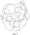
Figure 3 is a perspective view of a perimeter region of the head of drill bit offigure 2 including the first and a second imaginary circle; -
Figure 4 is a perspective view of a peripheral region of the head of the drill bit offigure 3 with selected components removed for illustrative purposes; -
Figure 5 is a perspective view of a further embodiment of a percussive rock drill bit according to one aspect of the present invention; -
Figure 6 is a plan view of the head of the drill bit offigure 5 including a first and a second imaginary circle at a peripheral region of the head; -
Figure 7 is a perspective view of a peripheral region of the head of the drill bit offigure 6 with selected components removed for illustrative purposes. - Referring to
figure 1 , adrill bit 10 comprises ahead 11 formed at one end of a generallyelongate shank 12.Head 11 andshank 12 are centred on alongitudinal axis 13 extending throughbit 10. Thehead 11 comprises an axially forward facing front face indicated generally byreference 15. According to the specific implementation,front face 15 is divided into a radiallyinnermost part 16 and an annular radiallyouter part 17 that surroundspart 16.Gauge support segments 14 project radially outward at a peripheral region ofhead 11 and are divided in a circumferential direction aroundaxis 13 by flushingchannels 21 extending axially fromfront face 15 towards the rearwardelongate shank 12.Channels 21 effectively dividehead 11 at its perimeter into thegauge support segments 14. - Each
gauge support segment 14 comprises an axially forward facinggauge mount face 22. Eachgauge mount face 22 is declined rearwardly fromfront face 15 and in particular radiallyouter part 17. Eachgauge mount face 22 is planar between a respective radiallyinner edge 24, a radiallyouter perimeter edge 26 and first andsecond edges gauge mount face 22 in the circumferential direction aroundaxis 13. Theinner edge 24 corresponds to a radiallyoutermost perimeter edge 23a of thefront face 15. Apart 23b ofperimeter edge 23a is positioned in a circumferential direction betweenneighbouring segments 14 and in particular gauge mount faces 22 and represents a radially outermost edge of eachextension portion 17a. - The angle by which each
gauge mount face 22 is declined to extend axially rearward fromperimeter edge 23a is greater than an angular orientation offront face 15 at both the radially inner andouter parts outer part axis 13. In particular,front face 15 may be considered to be at least partially dome shaped with the dome centred onaxis 13 in thatinner part 16 is raised axially relative toouter part 17 which is in turn positioned axially forward of each of the planar declined gauge mount faces 22. - Three flushing
fluid openings 20 are provided atfront face 15 and represent exit ends of passageways that extend internally withinhead 11 to communicate with an internal bore (not shown) extending axially withinshank 12. Accordingly, a flushing fluid, according to conventional configurations is capable of being delivered tofront face 15 viaopenings 20. As with conventional configurations, flushingchannels 21 are adapted to provide axial rearward transport of the flushing fluid together with rock fragments and fines to facilitate forward cutting. - A plurality of front cutting buttons are distributed at
front face 15 and include a set of radially innerfront cutting buttons 30 and a set of radially outerfront cutting buttons 19.Inner buttons 30 are provided within front faceinner part 16 whilstouter buttons 19 are provided at front faceouter part 17. Allbuttons respective part part front buttons 19 are positioned and mounted exclusively withinfront face 15 and no part ofbuttons 19 are mounted and positioned so as to extend from any one of the gauge mount faces 22. Arespective gauge button 18 is provided at eachsegment 14 so as to project axially forward from each respectivegauge mount face 22. Referring tofigures 2 , due to the angular orientation of eachgauge mount face 22, anaxis 25 of eachgauge button 18 is orientated radially outward at an acute angle frombit axis 13 such that eachgauge button 18 comprises anaxis 25 that is deflected radially outward. - Referring to
figures 2 and3 , the present invention may be defined relative to an imaginary circle indicated generally byreference 29 centred onaxis 13.Circle 29 comprises a diameter (radius) corresponding to aminimum separation distance 32 betweenaxis 13 and the radiallyinnermost edge 24 of each gauge mount face 22 (corresponding to the minimum separation distance ofperimeter edge 23a offront face 15 from axis 13). In particular,front face 15 atouter part 17 comprises an extension portion indicated generally byreference 17a that extends radially outward fromimaginary circle 29.Extension portion 17a accordingly extends in a circumferential direction between neighbouring gauge mount faces 22. As such,extension portion 17a overlaps radially with an inner portion of eachgauge mount face 22. - According to the specific implementation of
figure 1 to 4 , a portion of each radially outermostfront cutting button 19 is positioned atfront face 15 to extend from frontface extension portion 17a. That is, anexposed part 19a of button 19 (that is visible and projects axially forward from front face 15) extends from frontface extension portion 17a whilst afurther part 19b is mounted within and extends from a radially inner portion of front face 15 (within part 17). - Aspects of the invention may also be illustrated with reference to a second
imaginary circle 31 also centred onaxis 13.Second circle 31 comprises a diameter (radius) corresponding to aseparation distance 33 betweenaxis 13 and frontface perimeter edge 23b that extends in a circumferential direction between the respective ends of theinnermost edge 24 of gauge mount faces 22. Accordingly, secondimaginary circle 31 is positioned radially outside the firstimaginary circle 29. An exposed radiallyinner part 18a of each gauge button 18 (that is visible and projects axially forward from gauge mount face 22) is positioned so as to extend fromgauge mount face 22 radially within secondimaginary circle 31. A second radiallyouter portion 18b of eachgauge button 18 extends from a radially outer part of eachgauge mount face 22. Accordingly, the region radially between the first and secondimaginary circles face extension portions 17a, the radiallyouter part 19a of the radially outermostfront cutting buttons 19, a radially inner portion of eachgauge mount face 22 andinner part 18a of eachgauge button 18. As such,part 19a of the radially outermostfront cutting buttons 19 overlaps radially withpart 18a of each of thegauge buttons 18. This radial overlap is provided by frontface extension portion 17a that extends radially outward beyond firstimaginary circle 29. Such an arrangement is advantageous to enable the radially outermostfront buttons 19 to be positioned radially outward towardsgauge buttons 18 and optionally to overlap radially according to the embodiment offigures 1 to 4 . The frontface extension portion 17a provides structural support at the peripheral region ofhead 11 immediately inboard ofsegments 14 so as to provide sufficient material athead 11 to supportbuttons 19 at this peripheral region. Positioning the radially outerfront buttons 19 radially as close as possible to gaugebuttons 18 has been found to facilitate the cutting action undertaken bygauge buttons 18 which in turn reduces the gauge button wear rate and accordingly extends the operations lifetime of thebit 10. - A further embodiment of the present invention is described referring to
figures 5 and7 . According to the further embodiment,head 11 and in particularfront face 15 also comprises frontface extension portions 17a that extend radially outward beyondimaginary circle 29 centred onaxis 13 withcircle 29 touching the radiallyinnermost edges 24 of eachgauge mount face 22 as described with reference to the embodiment offigures 1 to 4 . Whilst nearly all the features, function and aspects of the two embodiments are the same, according to the further embodiment, the radially outermostfront buttons 19 are mounted exclusively withinimaginary circle 29 and do not extend into theextension portions 17a. However, referring to the secondimaginary circle 31, a radiallyinner part 18a of each of thegauge buttons 18 is positioned radially between the first and secondimaginary circles face extension portions 17a. According to this embodiment,extension portions 17a are advantageous to provide sufficient material athead 11 to support positionally and structurally each of the radially outermostfront buttons 19. With the embodiment offigures 5 to 7 , the radially outermostfront buttons 19 still provide assistance to the cutting action of thegauge buttons 18 as the circular cutting pathways created by therespective buttons buttons buttons 19 and 18) with such ridges being very susceptible to fracture, cracking and accordingly disintegration during the percussive drilling action. Accordingly, reduced wear rates of thegauge buttons 18 is provided to accordingly extend the operational lifetime ofbit 10.
Claims (15)
- A percussive rock drill bit (10) comprising:a head (11) provided at one end of an elongate shank (12), the head (11) having a forward facing front face (15);a plurality of front cutting inserts (19, 30) distributed at the front face (15);a plurality of peripheral gauge support segments (14) positioned at a perimeter of the front face (15) and each having a forward facing gauge mount face (22) being declined to extend axially rearward from the perimeter of the front face (15) and having an angular orientation different to the front face (15);at least one gauge cutting insert (18) provided at each respective gauge mount face (22);characterised in that:between the gauge mount faces (22) in a circumferential direction, an extension portion (17a) of the front face (15) extends radially outward beyond an imaginary first circle (29) centred on a longitudinal axis (13) of the drill bit (10), the circle (29) touching a radially innermost edge (24) of each gauge mount face (22).
- The drill bit as claimed in claim 1 wherein each gauge mount face (22) is planar.
- The drill bit as claimed in claim 2 wherein the radially innermost edge (24) of each gauge mount face (22) is linear.
- The drill bit as claimed in any one of claims 1 to 3 wherein the front face (15) comprises at least one angular orientation relative to an imaginary plane perpendicular to the longitudinal axis (13) and each gauge mount face (22) is declined relative to the imaginary plane by an angle greater than a maximum angle by which the front face (15) is declined relative to the imaginary plane.
- The drill bit as claimed in any preceding claim wherein at least a part of the front face (15) is declined to extend axially rearward such that an annular radially outer region (17) is positioned axially rearward relative to a radially inner region (16) of the front face (15).
- The drill bit as claimed in claim 5 wherein the radially inner region (16) has at least one first angular orientation and the annular radially outer region (17) has at least one second angular orientation different to the first angular orientation.
- The drill bit as claimed in any preceding claim wherein a radially inner part (18a) of each gauge cutting insert (18) is positioned radially within a second imaginary circle (31) that touches a radially outermost edge (23b) of each extension portion (17a).
- The drill bit as claimed in any preceding claim wherein each extension portion (17a) is positioned between neighbouring gauge mount faces (22) in a circumferential direction around the longitudinal axis (13) to radially overlap a radially inner region of the gauge mount faces (22).
- The drill bit as claimed in any preceding claim wherein a radially outermost exposed part (19a) of at least one radially outermost front cutting insert (19) is mounted on the extension portion (17a).
- The drill bit as claimed in claim 9 wherein said radially outermost exposed part 19a) is positioned radially outward beyond a radially innermost exposed part (18a) of at least one gauge cutting insert (18).
- The drill bit as claimed in claim 9 or 10 wherein said radially outermost exposed part (19a) is positioned between two neighbouring gauge cutting inserts (18) in a circumferential direction around the longitudinal axis (13).
- The drill bit as claimed in any preceding claim comprising a single gauge cutting insert (18) provided respectively at each gauge mount face (22).
- The drill bit as claimed in any preceding claim comprising an internal bore and at least one passageway extending axially from a forward end of the bore to emerge as at least one opening (20) at the front face (15).
- The drill bit as claimed in any preceding claim wherein the front cutting inserts (19, 30) are grouped into sets with each set positioned at a different radial distance from the longitudinal axis and each front cutting insert (19, 30) of each respective set is positioned at the same radial distance.
- The drill bit as claimed in claim 14 comprising a first radially inner set (30) and a second radially outer set (19), the radially outer set (19) including a radially outermost front cutting insert.
Priority Applications (2)
| Application Number | Priority Date | Filing Date | Title |
|---|---|---|---|
| EP18191627.1A EP3617438A1 (en) | 2018-08-30 | 2018-08-30 | Percussive drill bit with radially extended front face |
| PCT/EP2019/071967 WO2020043505A1 (en) | 2018-08-30 | 2019-08-15 | Percussive drill bit with radially extended front face |
Applications Claiming Priority (1)
| Application Number | Priority Date | Filing Date | Title |
|---|---|---|---|
| EP18191627.1A EP3617438A1 (en) | 2018-08-30 | 2018-08-30 | Percussive drill bit with radially extended front face |
Publications (1)
| Publication Number | Publication Date |
|---|---|
| EP3617438A1 true EP3617438A1 (en) | 2020-03-04 |
Family
ID=63449324
Family Applications (1)
| Application Number | Title | Priority Date | Filing Date |
|---|---|---|---|
| EP18191627.1A Withdrawn EP3617438A1 (en) | 2018-08-30 | 2018-08-30 | Percussive drill bit with radially extended front face |
Country Status (2)
| Country | Link |
|---|---|
| EP (1) | EP3617438A1 (en) |
| WO (1) | WO2020043505A1 (en) |
Families Citing this family (2)
| Publication number | Priority date | Publication date | Assignee | Title |
|---|---|---|---|---|
| CN121866389A (en) * | 2023-09-15 | 2026-04-14 | 安百拓凿岩钎具有限公司 | drill |
| CN119914177A (en) | 2023-10-30 | 2025-05-02 | 肯纳金属印度有限公司 | Drilling tools |
Citations (9)
| Publication number | Priority date | Publication date | Assignee | Title |
|---|---|---|---|---|
| US6105693A (en) * | 1999-02-18 | 2000-08-22 | Sandvik Ab | Partially enhanced percussive drill bit |
| US20020153174A1 (en) | 1999-11-25 | 2002-10-24 | Johan Linden | Percussive rock drill bit and buttons therefor and method for manufacturing drill bit |
| US20060060389A1 (en) * | 2004-09-21 | 2006-03-23 | Sandvik Intellectual Property Ab | Rock drill bit having outer and inner rock-crushing buttons |
| US20070039761A1 (en) | 2004-05-25 | 2007-02-22 | Cruz Antonio Mari G L | Percussive drill bit, drilling system comprising such a drill bit and method of drilling a bore hole |
| US20080087473A1 (en) * | 2006-10-13 | 2008-04-17 | Hall David R | Percussive Drill Bit |
| WO2008066445A1 (en) | 2006-11-29 | 2008-06-05 | Sandvik Intellectual Property Ab | A button bit |
| WO2012174607A1 (en) | 2011-06-24 | 2012-12-27 | Drilling Tools Australia Pty Ltd | A drill bit |
| GB2516626A (en) * | 2013-07-25 | 2015-02-04 | Padley & Venables Ltd | Percussive Drill Bit |
| US20180066477A1 (en) * | 2015-02-19 | 2018-03-08 | Sandvik Intellectual Property Ab | Drill bit for improved transport of cuttings |
-
2018
- 2018-08-30 EP EP18191627.1A patent/EP3617438A1/en not_active Withdrawn
-
2019
- 2019-08-15 WO PCT/EP2019/071967 patent/WO2020043505A1/en not_active Ceased
Patent Citations (10)
| Publication number | Priority date | Publication date | Assignee | Title |
|---|---|---|---|---|
| US6105693A (en) * | 1999-02-18 | 2000-08-22 | Sandvik Ab | Partially enhanced percussive drill bit |
| US20020153174A1 (en) | 1999-11-25 | 2002-10-24 | Johan Linden | Percussive rock drill bit and buttons therefor and method for manufacturing drill bit |
| US20070039761A1 (en) | 2004-05-25 | 2007-02-22 | Cruz Antonio Mari G L | Percussive drill bit, drilling system comprising such a drill bit and method of drilling a bore hole |
| US20060060389A1 (en) * | 2004-09-21 | 2006-03-23 | Sandvik Intellectual Property Ab | Rock drill bit having outer and inner rock-crushing buttons |
| WO2006033606A1 (en) | 2004-09-21 | 2006-03-30 | Sandvik Intellectual Property Ab | Rock drill bit |
| US20080087473A1 (en) * | 2006-10-13 | 2008-04-17 | Hall David R | Percussive Drill Bit |
| WO2008066445A1 (en) | 2006-11-29 | 2008-06-05 | Sandvik Intellectual Property Ab | A button bit |
| WO2012174607A1 (en) | 2011-06-24 | 2012-12-27 | Drilling Tools Australia Pty Ltd | A drill bit |
| GB2516626A (en) * | 2013-07-25 | 2015-02-04 | Padley & Venables Ltd | Percussive Drill Bit |
| US20180066477A1 (en) * | 2015-02-19 | 2018-03-08 | Sandvik Intellectual Property Ab | Drill bit for improved transport of cuttings |
Also Published As
| Publication number | Publication date |
|---|---|
| WO2020043505A1 (en) | 2020-03-05 |
Similar Documents
| Publication | Publication Date | Title |
|---|---|---|
| EP2902583B1 (en) | Percussive rock drill bit with flushing grooves | |
| EP2865843B1 (en) | Percussive rock drill bit with optimised gauge buttons | |
| EP2799659A1 (en) | Percussive rock drill bit | |
| AU2014344104A1 (en) | Percussive rock drill bit with optimised gauge buttons | |
| EP3059383B1 (en) | Drill bit for improved transport of cuttings | |
| EP2990589B1 (en) | Drill bit with recessed cutting face | |
| EP3617439B1 (en) | Drill bit with curved sludge grooves | |
| CN106103879B (en) | The drill hammer of preceding cutting tip with multiple groups | |
| WO2020043505A1 (en) | Percussive drill bit with radially extended front face | |
| EP3690180A1 (en) | Percussion drill bit with wear inserts | |
| CN113383143B (en) | Inserts for journal legs and/or conical cutters for rotary drill tools | |
| OA21130A (en) | Carved out drill bit. |
Legal Events
| Date | Code | Title | Description |
|---|---|---|---|
| PUAI | Public reference made under article 153(3) epc to a published international application that has entered the european phase |
Free format text: ORIGINAL CODE: 0009012 |
|
| STAA | Information on the status of an ep patent application or granted ep patent |
Free format text: STATUS: THE APPLICATION HAS BEEN PUBLISHED |
|
| AK | Designated contracting states |
Kind code of ref document: A1 Designated state(s): AL AT BE BG CH CY CZ DE DK EE ES FI FR GB GR HR HU IE IS IT LI LT LU LV MC MK MT NL NO PL PT RO RS SE SI SK SM TR |
|
| AX | Request for extension of the european patent |
Extension state: BA ME |
|
| STAA | Information on the status of an ep patent application or granted ep patent |
Free format text: STATUS: REQUEST FOR EXAMINATION WAS MADE |
|
| 17P | Request for examination filed |
Effective date: 20200904 |
|
| RBV | Designated contracting states (corrected) |
Designated state(s): AL AT BE BG CH CY CZ DE DK EE ES FI FR GB GR HR HU IE IS IT LI LT LU LV MC MK MT NL NO PL PT RO RS SE SI SK SM TR |
|
| STAA | Information on the status of an ep patent application or granted ep patent |
Free format text: STATUS: EXAMINATION IS IN PROGRESS |
|
| 17Q | First examination report despatched |
Effective date: 20201118 |
|
| STAA | Information on the status of an ep patent application or granted ep patent |
Free format text: STATUS: THE APPLICATION HAS BEEN WITHDRAWN |
|
| 18W | Application withdrawn |
Effective date: 20201218 |