EP3617375A1 - Laundry appliance with user-friendly drawer - Google Patents
Laundry appliance with user-friendly drawer Download PDFInfo
- Publication number
- EP3617375A1 EP3617375A1 EP18191663.6A EP18191663A EP3617375A1 EP 3617375 A1 EP3617375 A1 EP 3617375A1 EP 18191663 A EP18191663 A EP 18191663A EP 3617375 A1 EP3617375 A1 EP 3617375A1
- Authority
- EP
- European Patent Office
- Prior art keywords
- drawer
- laundry treatment
- component
- compartment
- sub
- Prior art date
- Legal status (The legal status is an assumption and is not a legal conclusion. Google has not performed a legal analysis and makes no representation as to the accuracy of the status listed.)
- Granted
Links
Images



Classifications
-
- D—TEXTILES; PAPER
- D06—TREATMENT OF TEXTILES OR THE LIKE; LAUNDERING; FLEXIBLE MATERIALS NOT OTHERWISE PROVIDED FOR
- D06F—LAUNDERING, DRYING, IRONING, PRESSING OR FOLDING TEXTILE ARTICLES
- D06F39/00—Details of washing machines not specific to a single type of machines covered by groups D06F9/00 - D06F27/00
- D06F39/02—Devices for adding soap or other washing agents
Definitions
- the present invention generally relates to the field of laundry treatment appliances (hereinafter, concisely, "laundry appliances”), and particularly to laundry appliances for treating, e.g. washing, items (such as linen, clothes, garments, shoes, and the like), such as laundry washing appliances and laundry washing appliances also implementing laundry drying functions (also referred to as washers/dryers). More particularly, the present invention relates to a laundry appliance with an improved and user-friendly drawer.
- laundry appliances for treating, e.g. washing, items (such as linen, clothes, garments, shoes, and the like), such as laundry washing appliances and laundry washing appliances also implementing laundry drying functions (also referred to as washers/dryers). More particularly, the present invention relates to a laundry appliance with an improved and user-friendly drawer.
- a laundry appliance typically comprises a drawer having drawer compartments for containing one or more treatment agents (such as liquid and powder treatment agents), and a drawer seat for slidably housing the drawer within it.
- treatment agents such as liquid and powder treatment agents
- a typical drawer comprises one or more components that can be actuated by the user (hereinafter, actuatable components).
- actuatable components of the drawer are a detach component for allowing a drawer handle to be detached from a drawer body, one or more adapter components each one configured to be reversibly inserted into a respective drawer compartment for adapting it to liquid or powder treatment agents, an extraction component for reversibly extracting the drawer from the drawer seat, one or more access components (e.g., doors) for selectively accessing respective drawer compartment(s), and one or more plug components for selectively plugging or unplugging emptying holes of respective drawer compartments.
- the drawers of currently marketed laundry appliances comprise each one a relatively high number of actuatable components (for example, all or almost all of the above mentioned actuatable components).
- actuatable components together with the remaining parts of the drawer, typically define as a whole a generally uniform and substantially impersonal appearance of the drawer.
- the Applicant has realized that a uniform and impersonal appearance of the drawer, besides being not very gratifying for the user in terms of aesthetics, may also negatively affect user experience when the user interacts with it.
- a drawer having a uniform appearance and comprising a relatively high number of actuatable components may be disclouraging for the user, in that the actuatable components are not easily recognizable and/or actuatable by the user without resorting to the instruction manual of the laundry appliance or other forms of help or assistance.
- An aspect of the present invention relates to a laundry treatment appliance comprising a drawer for containing at least one laundry treatment agent, and at least two components associated with said drawer and that can be manually actuated by a user while interacting with the drawer.
- Said at least two components preferably comprise, at least on respective portions thereof, respective markers with at least one common appearance feature for allowing the user to visually identify said at least two components in the drawer.
- said at least one common appearance feature comprises a common color of said respective portions of said at least two components.
- said markers comprise, for at least one of said at least two components, a function indicator allowing the user to recognize a function of the respective component.
- the function indicators of said at least two components comprise at least one among textual and/or sign indicators.
- the laundry treatment appliance further comprises a user interface having at least one control element for allowing the user to control at least one operating parameter of a laundry treatment cycle.
- the user interface also comprises at least one status indicator for indicating to the user a status of the laundry treatment appliance and/or a status of a laundry treatment cycle.
- one or more of said at least one operating parameter and said at least one status indicator is associated each one with a respective one of said markers.
- said at least two components comprise at least two among:
- At least one first drawer compartment of said at least one drawer compartment is adapted to contain a single dose of said at least one laundry treatment agent, and/or at least one second drawer compartment of said at least one drawer compartment is adapted to contain multiple doses of said at least one laundry treatment agent.
- said drawer body is connectable with said drawer handle in a releasable way through a coupling arrangement.
- Said coupling arrangement preferably comprises:
- said at least one adapter component comprises a container adapted to be reversibly housed into said at least one drawer compartment.
- the container preferably comprises a grip portion for allowing insertion and removal of the at least one adapter component into and from, respectively, said at least one drawer compartment.
- the marker of the at least one adapter component is advantageously provided on said grip portion.
- said grip portion comprises an inclined edge that identifies a gap between the container and the at least one drawer compartment when the container is housed in the least one drawer compartment.
- the at least one access component comprises a door that can be actuated between open and closed conditions for respectively allowing and preventing access to the at least one drawer compartment.
- the door preferably comprises a grip portion for actuating the door.
- the marker of the at least one access component is advantageously provided on said grip portion.
- the grip portion when the door is in the closed condition, the grip portion is spaced apart from the least one drawer compartment thereby allowing the user to grasp the grip portion.
- the door comprises an abutment portion that, when the door is in the closed position, preferably abuts on a portion of a rim region of the at least one drawer compartment.
- the marker of the at least one access component is advantageously provided further on said abutment portion.
- said at least one first drawer compartment comprises at least two first drawer compartments.
- Each one of said at least two first drawer compartments comprises, at least on respective portions thereof, respective further markers with at least one further common appearance feature different from the common appearance feature and, preferably, from said generally uniform appearance of the drawer. In this way, the user is allowed to visually identify said at least two first drawer compartments.
- said extraction component is associated with drawer seat and preferably comprises:
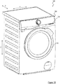
- FIGS 1A and 1B show perspective views of a laundry appliance 100 according to an embodiment of the present invention.
- the laundry appliance 100 is a washing machine.
- the present invention applies to other types of laundry appliances (for example combined washers/dryers, i.e. washing machines also having laundry drying functions).
- the laundry appliance 100 comprises a (e.g., parallepiped-shaped) cabinet 105, which preferably accommodates a treatment chamber (i.e., a laundry washing chamber in the example herein considered of a washing machine) for performing a laundry treatment cycle on items housed therein ( i.e., a washing cycle on a laundry load in the example herein considered of a washing machine).
- a treatment chamber i.e., a laundry washing chamber in the example herein considered of a washing machine
- the laundry washing chamber comprises a washing tub (not shown) and, within it, a (e.g., rotatable) washing basket or drum (not shown) adapted to contain the laundry load to be washed.
- a cabinet front has a loading opening providing an access to the drum for loading/unloading the laundry load, a door 110 (shown in a closed position in Figures 1A and 1B ) being provided for sealably closing the loading opening during the operation of the laundry appliance 100.
- the laundry appliance 100 also comprises, enclosed in the cabinet 105, electrical/electronic/mechanical/hydraulic components for the operation of the laundry appliance 100 (such as for example motor, electromechanical valves, pumps and impellers of the hydraulic apparatus, one or more heating elements for heating water/treatment agents/air).
- electrical/electronic/mechanical/hydraulic components for the operation of the laundry appliance 100 (such as for example motor, electromechanical valves, pumps and impellers of the hydraulic apparatus, one or more heating elements for heating water/treatment agents/air).
- the laundry appliance 100 further comprises a drawer 115 for containing one or more laundry treatment agents (or, concisely, treatment agents), such as liquid and powder treatment agents including, but not limited to, washing detergents, rinsing detergents, bleaches and softeners.
- the laundry appliance 100 also comprises a drawer seat 120 for housing the drawer 115, the drawer being advantageously configured to slide into the drawer seat 120, along a longitudinal or sliding direction X, between an extracted position (shown in Figure 1A ) and a retracted position (shown in Figure 1B ).
- the drawer seat 120 is preferably provided on a top part of a cabinet front.
- the laundry appliance 100 further comprises a user interface 125, the user interface 125 being preferably provided on the top part of the cabinet front, more preferably next to the drawer seat 120 along a transversal direction Y orthogonal to the longitudinal direction X.
- the user interface 125 comprises a display unit, not shown, for visually displaying one or more pieces of information; the display unit may for example be a light emitting polymer display (LPD), a liquid crystal display, a thin film transistor-liquid crystal display, or an organic light-emitting diode display.
- the display unit may for example be a light emitting polymer display (LPD), a liquid crystal display, a thin film transistor-liquid crystal display, or an organic light-emitting diode display.
- the user interface 125 preferably comprises one or more control elements (e.g., selection buttons and/or knobs) for allowing the user to select a washing cycle and to control one or more operating parameters of the selected washing cycle (including, but not limited to, temperature, laundry load dirt level, spin speed, start time delay, drawer compartment selection, treatment agent selection).
- control elements e.g., selection buttons and/or knobs
- operating parameters of the selected washing cycle including, but not limited to, temperature, laundry load dirt level, spin speed, start time delay, drawer compartment selection, treatment agent selection.
- the user interface 125 preferably comprises one or more status indicators for indicating to the user a status of the laundry appliance 100; for the purposes of the present disclosure, the status indicators are configured to indicate the status of one or more components of the laundry appliances 100 (for example, or one or more drawer components that can be actuated by the user, as better discussed in the following) and/or a status of the washing cycle (including, but not limited to, information about a residual time to the end of the ongoing washing cycle, and/or information about a current phase of the ongoing washing cycle, and/or selected parameters for the ongoing washing cycle, and/or selected drawer compartment, and/or selected treatment agent).
- the status indicators are configured to indicate the status of one or more components of the laundry appliances 100 (for example, or one or more drawer components that can be actuated by the user, as better discussed in the following) and/or a status of the washing cycle (including, but not limited to, information about a residual time to the end of the ongoing washing cycle, and/or information about a current phase of the ongoing washing cycle, and/or
- Figure 2A shows perspective views of the drawer 115 according to an embodiment of the present invention.
- Figure 2A will be discussed jointly with Figure 2B , which shows a perspective exploded view of the drawer 115, with Figure 2C , which shows a perspective exploded view of a drawer cover and of a door associated therewith, and with Figure 2D , which shows a perspective and partially exploded view from behind of the drawer 115.
- the drawer 115 is generally made of a single plastic material, exception made for some parts thereof which advantageously comprise materials conveniently different from the plastic material of most of the drawer 115 (as detailed below while discussing embodiments of the present invention).
- the drawer 115 preferably comprises a drawer handle 205 allowing the user to slidably move the drawer 115 between the extracted position and the retracted position when it is fitted into the drawer seat 120, and a drawer body 210 to which the drawer handle 205 is adapted to be mounted (advantageously, in a removable or reversible way, as better discussed in the following).
- the drawer body 210 preferably comprises one or more (two, in the example at issue) drawer compartments 215 1 ,215 2 each one adapted to contain a single dose of a respective treatment agent for performing a single washing cycle, hereinafter referred to as mono-dose compartments 215 1 ,215 2 ; just as an example, the mono-dose compartment 215 1 may be arranged to contain a single dose of a powder or liquid washing detergent, whereas the mono-dose compartment 215 2 may be arranged to contain a single dose of a powder or liquid or pearl softener.
- the drawer 115 preferably comprises one or more (two, in the example at issue) drawer compartments 220 1 ,220 2 each one adapted to contain multiple doses of a respective treatment agent for performing multiple washing cycles, hereinafter referred to as multi-dose compartments: therefore, the exemplary considered laundry appliance 100 is configured to implement an auto-dosing functionality in which, at each washing cycle (and when the auto-dosing functionality is enabled), a predetermined amount of treatment agent is automatically taken ( e.g., by means of a pump, preferably a peristaltic pump, not shown) from one or both of the multi-dose compartments 220 1 ,220 2 .
- the multi-dose compartment 220 1 may be arranged to contain multiple doses of a liquid washing detergent
- the multi-dose compartment 220 2 may be arranged to contain a multiple doses of a liquid softener.
- the mono-dose compartments 215 1 ,215 2 are formed side by side along the transversal direction Y; more preferably, the mono-dose compartments 215 1 ,215 2 are formed in an area of the drawer body 210 that, when the drawer handle 205 is mounted on the drawer body 210, is proximal to the drawer handle 205 (hereinafter referred to as front area of the drawer body 210 ).
- each mono-dose compartment 215 1 ,215 2 extends in depth (i.e., along a vertical direction Z orthogonal to the longitudinal X and transversal Y directions) from a top of the drawer body 210 that identifies a respective access mouth for allowing treatment agent loading from above.
- the drawer 115 also comprises one or more adapter components each one configured to be inserted into or removed from a respective mono-dose compartment 215 1 ,215 2 for adapting it to, respectively, liquid or powder treatment agents.
- a single adapter component is provided, namely an adapter component (globally denoted by the number reference 215 1,AD ) configured to be reversibly housed into the mono-dose compartment 215 1
- the adapter component 215 1,AD comprises a container (for example, a cup-shaped container) C 1,AD adapted to be reversibly housed into the mono-dose compartment 215 1 when a liquid treatment agent is intended to be loaded.
- the adapter component 215 1,AD advantageously comprises a siphon pipe SP 1,AD (preferably, formed in a single piece with the container C 1,AD ) to induce a siphon phenomenon, and a siphon cap SC 1,AD coupled (or adapted to be coupled) to the siphon pipe SP 1,AD : when the liquid washing detergent in the container C 1,AD exceeds a limit level, a siphon phenomenon occurs, whereby the liquid washing agent to be supplied during the washing cycle is previously discharged through the siphon pipe SP 1,AD .
- the container C 1,AD fits the access mouth of the mono-dose compartment 215 1 , exception made for an inclined edge IE 1,AD of the container C 1,AD .
- a gap is defined between the mono-dose compartment 215 1 ( e.g., a corner of the substantially square-like shape of its access mouth) and the inclined edge IE 1,AD of the container C 1,AD , whereby the inclined edge IE 1,AD of the container C 1,AD defines a grip portion adapted to be grasped for easily actuating ( e.g., inserting and removed into and from the mono-dose compartment 215 1 ) the container C 1,AD (or, more generally, the adapter component 215 1,AD ) .
- At least part of the inclined edge IE 1,AD (e.g., the top edge part that, when the drawer 115 is fitted into the drawer seat 120, is visible by as user looking at the drawer 115 ) is made of a material different from the plastic material of most of the drawer 115.
- the material of the inclined edge IE 1,AD (or of part thereof) may for example comprise a synthetic rubber or a thermoplastic material, e.g. formed by overmolding or co-molding techniques.
- a container for example, a cup-shaped container
- a siphon pipe (not visible, and preferably formed in a single piece with the container C 2,AD ) to induce a siphon phenomenon
- the container C 2,AD may also comprise a grip portion ( e.g., similar to the grip portion of the container C 1,AD ) to allow insertion and removal thereof into and from, respectively, the mono-dose compartment 215 2 .
- the multi-dose compartments 220 1 ,220 2 are formed side by side along the transversal direction Y. More preferably, the multi-dose compartments 220 1 ,220 2 are formed in an area of the drawer body 210 (hereinafter referred to as rear area of the drawer body 210 ) that, along the sliding direction X, is rearward with respect to the front area of the drawer body 210 ( i.e., the area of the drawer body 210 where the mono-dose compartments 215 1 ,215 2 are provided).
- the front and rear areas of the drawer body 210 are properly different in size, and particularly the rear area of the drawer body 210 is larger than the front area of the drawer body 210 ( e.g., the rear area of the drawer body 210 being for example from 2 to 4 times larger than the front area of the drawer body 210 ); when, as herein exemplary considered, same extensions in depth of the mono-dose 215 1 ,215 2 and multi-dose 220 1 ,220 2 compartments are assumed, having the rear area of the drawer body 210 larger than the front area of the drawer body 210 translates into correspondingly different capacities of the mono-dose 215 1 ,215 2 and multi-dose 220 1 ,220 2 compartments (with the multi-dose compartments 220 1 ,220 2 that are sized to store larger amounts of treatment agent as compared to the mono-dose compartments 215 1 ,215 2 ) .
- Forming the multi-dose compartments 220 1 ,220 2 behind the mono-dose compartments 215 1 ,215 2 is advantageous in that a low or relatively low extraction of the drawer 115 is required for allowing the user to load the treatment agents in the mono-dose compartments 215 1 ,215 2 (on the contrary, forming the mono-dose compartments 215 1 ,215 2 behind the multi-dose compartments 220 1 ,220 2 would dramatically impair the mechanical stability of the drawer 115, for example when extracting the drawer 115 to load the treatment agent in the mono-dose compartments 215 1 ,215 2 and a certain amount of treatment agent is still stored in one or more of the multi-dose compartments 220 1 ,220 2 ) .
- one or more emptying holes each one associated with a respective multi-dose compartment 220 1 ,220 2 are provided in the drawer body 210 for emptying the respective multi-dose compartment 220 1 ,220 2 , i.e. for discharging it from the treatment agent contained therein ( e.g. for maintenance or cleaning of the drawer 115 ).
- emptying holes 210 H1 ,210 H2 are provided in the drawer body 210, the emptying hole 210 H1 being associated with the multi-dose compartment 220 1 and the emptying hole 210 H2 being associated with the multi-dose compartment 220 2 - however, in further embodiments of the present invention (not shown), emptying holes associated with the mono-dose compartments 215 1 ,215 2 may be provided additionally or alternatively to the emptying holes 210 H1 ,210 H2 .
- each emptying hole 210 H1 ,210 H2 comprises a circular opening located on a respective side of the drawer body 210 (preferably, a bottom part thereof), i.e. the side of the drawer body 210 that delimits the respective multi-dose compartment 220 1 ,220 2 along the transversal direction Y.
- Each emptying hole 210 H1 ,210 H2 is advantageously closable or pluggable by means of a selectively removable plug component (or, concisely, plug) 210 P1 ,210 P2 (the plugs 210 P1 ,210 P2 being both visible in Figure 2B detached or removed from the respective emptying holes 210 H1 ,210 H2 , whereas a plug covering the respective emptying hole, such as the plug 210 P1 covering the emptying hole 210 H1 , is visible in Figure 2A ).
- a selectively removable plug component or, concisely, plug
- each emptying hole 210 H1 ,210 H2 is located, along the sliding direction X, in an advanced position of the drawer body 210 ( i.e., towards the drawer handle 205 ); therefore, when the drawer 115 is sufficiently extracted or pulled out, the plugs 210 P1 ,210 P2 become accessible and can be removed to free the emptying holes 210 H1 ,210 H2 . Therefore, upon sufficient extraction or pulling out of the drawer 115 and removal of the plug(s) 210 P1 ,210 P2 , the treatment agent(s) in the multi-dose compartment(s) 220 1 ,220 2 is caused to flow outside through the respective emptying hole(s) 210 H1 ,210 H2 , e.g.
- attachment or connection or coupling or fitting of the drawer 115 is preferably releasable (so as to detach or disconnect or decouple or unfit the drawer 115 from the drawer seat 120 ) by means of an extraction component (only a part thereof being visible in Figure 2D and globally denoted by the number reference 210 E ) .
- the extraction component 210 E is preferably coupled or coupleable to the drawer seat 120 (advantageously, on a front part thereof that, in use, faces the drawer handle 205 ). More preferably, the extraction component 210 E comprises a releasable locking element 210 E,LOC for locking the extraction component 210 E in a slot 120s of the drawer seat 120 (thus firmly securing the extraction component 210 E to the drawer seat 120 during actuation of the extraction component 210 E ) .
- the extraction component 210 E further comprises an extraction actuator 210 E,ACT (visible in Figure 2D ) actuatable by the user in order to decouple the drawer 115 from the drawer seat 120.
- the extraction component 210 E comprises a catch portion 210 E,CAT adapted to engage a blocking portion (not shown) of the drawer body 210; more preferably, the extraction actuator 210 E,ACT is mechanically coupled to the catch portion 210 E,CAT for operating the extraction component 210 E between a first condition in which the catch portion 210 E,CAT engages the blocking portion thereby preventing extraction of the drawer 115 from the drawer seat 120 and a second condition in which the catch portion 210 E,CAT disengages the blocking portion thereby allowing extraction of the drawer 115 from the drawer seat 120 (with the extraction component 210 E that, when the drawer 115 is extracted from the drawer seat 120, is firmly coupled to the drawer seat 120 by means of the locking element 210 E,LOC being fitted in the slot 120s ).
- the drawer 115 also comprises a drawer cover 225 for covering the drawer body 210. More preferably, the drawer cover 225 is configured to cover the rear area of the drawer body 210, thus leaving uncovered the front area of the drawer body 210, and hence the mono-dose compartments 215 1 ,215 2 ; the mono-dose compartments 215 1 ,215 2 can therefore be directly accessed from above ( i.e., through the respective access mouths) for loading the treatment agents therein.
- the drawer cover 225 comprises one or more access openings each one for accessing a respective multi-dose compartment 220 1 ,220 2 for loading the treatment agent; in the example at issue in which the drawer body 210 comprises two multi-dose compartments 220 1 ,220 2 , two access openings 230 1 ,230 2 are provided in the drawer cover 225.
- One or more of the access openings 230 1 ,230 2 (preferably, each one of the access openings 230 1 ,230 2 ) comprises, at an inner part thereof, a level indicator for indicating a level of treatment agent that is recommended to be loaded in the respective multi-dose compartment 220 1 ,220 2 .
- a level indicator for indicating a level of treatment agent that is recommended to be loaded in the respective multi-dose compartment 220 1 ,220 2 .
- only one level indicator is assumed, for example the level indicator associated with the access opening 230 1 (visible in Figures 2B and 2C and denoted by the number reference 230 1L ) .
- Each level indicator such as the level indicator 230 1L , may for example be in the form of a horizontally projecting fin preferably formed at a proper inner wall of the respective access opening ( e.g., in a single piece with it), more preferably at a corner of the substantially square-like shape of the respective access opening.
- the access openings 230 1 ,230 2 are formed in the drawer cover 225 side by side along the transversal direction Y.
- the access openings 230 1 ,230 2 are advantageously formed in an area 225 A of the drawer cover 225 that, when the drawer cover 225 is mounted on the drawer body 210, is proximal to the front area of the drawer body 210 ( i.e., the area of the drawer body 210 where the mono-dose compartments 215 1 ,215 2 are provided), or substantially proximal thereto (as detailed here below): therefore, a low or relatively low extraction of the drawer 115 is required for allowing the user to load the treatment agents in the multi-dose-compartments 220 1 ,220 2 (an excessive extraction of the drawer 115 would instead impair the mechanical stability of the drawer 115, essentially due to its elongated shape and/or to its relatively heavy weight, especially when treatment agents are contained therein).
- the area 225 A of the drawer cover 225, and hence the access openings 230 1 ,230 2 are formed at such a distance (along the longitudinal direction X ) from the access mouths of the mono-dose compartments 215 1 ,215 2 that a free area 240 is defined in the drawer cover 225 adapted to contain one or more pieces of information for the user.
- Exemplary pieces of information that may be contained in the free area 240 are information about correct dosages of the treatment agents according to treatments agents and/or water chemical parameters, and/or general indications or instructions about a correct operation or setting of the auto-dosing functionality.
- the area 225 A of the drawer cover 225 in which the access openings 230 1 ,230 2 are formed is a recessed area 225 A , the recessed area 225 A being recessed (along the vertical direction Z ) with respect to a top profile of the drawer cover 225.
- the recessed area 225 A preferably comprises a rim region 225 AR that substantially surrounds the access openings 230 1 ,230 2 .
- the rim region 225 AR preferably comprises a front portion 225 AR,F that, in use, is proximal to the free region 240, and side portions 225 AR,S1 ,225 AR,S2 .
- each side portion 225 AR,S1 ,225 AR,S2 of the rim region 225 AR opens to a respective side edge portion 225 S1 ,225 S2 of the drawer cover 225 (in order to house a respective grip portion, as discussed below); in other words, the top profile of the drawer cover 225, and particularly the side edge portion thereof, stops in correspondence of each side portion 225 AR,S1 ,225 AR,S2 of the rim region 225 AR .
- the laundry appliance 100 preferably comprises one or more access components associated with the drawer 115 for selectively covering and uncovering the access openings 230 1 ,230 2 for respectively preventing and allowing access to the respective multi-dose compartments 220 1 ,220 2 (in the exemplary considered embodiment, no access components are provided for selectively covering and uncovering the access mouths of the mono-dose compartments 215 1 ,215 2 , however this should not be construed as a limitation).
- the access component may for example be a door 245 coupled or coupleable to the drawer cover 225 at the respective access opening 230 1 ,230 2 .
- the door 245 is a flap door pivotally coupled to the drawer cover 225 so as to be actuatable by the user between an open position (shown in the bottom drawing of Figure 2A ) and a closed position (shown in the top drawing of Figure 2A ) for jointly uncovering and covering, respectively, both the access openings 230 1 ,230 2 .
- a single door 245 associated with both access openings 230 1 ,230 2 is assumed in the exemplary considered embodiment - in any case, in alternative embodiments of the present invention, not shown, two doors may be provided, each door being associated with a respective access opening 230 1 ,230 2 .
- the door 245 fits the recessed area 225 A of the drawer cover 225 and is flush with the top profile of the drawer cover 225 when the door 245 is in the closed position.
- the door 245 preferably comprises an abutment portion 245 AB that, when the door 245 is in the closed position, abuts on the front portion 225 AR,F of the rim region 225 AR .
- the abutment portion 245 AB is preferably part of a sealing member of the door 245, the sealing member being for example made of synthetic rubber or thermoplastic materials, or other materials having sufficiently resilient properties to ensure good adherence when coming in contact with the front portion 225 AR,F of the rim region 225 AR ( i.e., door 245 in the closed position).
- the sealing member is advantageously overmolded to a body 245 B of the door 245, the body 245 B of the door 245 being for example made of same or similar plastic material of most of the drawer 115 (for example, a plastic rigid material).
- the door 245 further comprises one or more grip portions for actuating the door 245.
- the door 245 comprises two grip portions 245 G1 ,245 G2 , each one facing a respective side portion 245 AR,S1 ,245 AR,S2 of the rim region 245 AR when the door 245 is in the closed position.
- the grip portions 245 G1 ,245 G2 are preferably formed in a single piece with the abutment portion 245 AB , the grip portions 245 G1 ,245 G2 being therefore part of the sealing member. More preferably, the grip portions 245 G1 ,245 G2 are designed such that, when the door 245 is in the closed position, each grip portion 245 G1 ,245 G2 is flush (along the vertical direction Z ) with the respective side edge portion 225 S1 ,225 S2 of the drawer cover 225.
- the grip portions 245 G1 ,245 G2 are designed such that, when the door 245 is in the closed position, each grip portion 245 G1 ,245 G2 is spaced apart from the multi-dose compartment 220 1 ,220 2 along the vertical direction Z.
- each grip portion 245 G1 ,245 G2 has a thickness lower than the thickness of the abutment portion 245 AB , such that, when the door 245 is in the closed position and the abutment portion 245 AB abuts the front portion 245 AR,F of the rim region 245 AR , each grip portion 245 G1 ,245 G2 and the respective faced side portion 225 AR,S1 ,225 AR,S2 of the rim region 245 AR are spaced apart from each other (along the vertical direction Z ) by a gap (visible in the top drawing of Figure 2A ) that allows the user to grasp the grip portion 245 G1 ,245 G2 .
- the drawer 115 can be moved between the extracted and retracted positions by acting on the drawer handle 205.
- the drawer handle 205 may be reversibly coupled or connected to the drawer body 210, for example by means of a coupling arrangement associated with the drawer 115.
- the coupling arrangement comprises sliding means (such as the rail elements 210 R1 ,210 R2 visible in Figure 2B ) arranged on the drawer body 210 along the transversal direction Y (which identifies a coupling direction between the drawer handle 205 and the drawer body 210 ) and sliding means (such as rail elements 205 R1 ,205 R2 visible in Figure 2D ) arranged on the drawer handle 225 along the transversal direction Y.
- the rail elements 210 R1 ,210 R2 of the drawer body 210 are adapted to slidably engage with the rail elements 205 R1 ,205 R2 of the drawer handle 205 for allowing the drawer handle 205 to move with respect to the drawer body 210 along the transversal direction Y.
- the coupling arrangement also comprises a detach component 250 configured to selectively prevent or allow the movement of the drawer handle 205 with respect to the drawer body 210 along the transversal direction Y (whereby when such a movement is allowed, detachment or decoupling between the drawer handle 205 and the drawer body 210 can be obtained).
- the detach component 250 is a detent element located on an inner face of the drawer handle 205 and configured to be switched between a locked configuration, in which the detent element 250 engages a corresponding detent region 255 (e.g. a window, preferably a rectangular window) in a front wall of the drawer body 210, and an unlocked configuration, in which the detent element 250 is disengaged from the detent region 255 thereby allowing the movement of the drawer handle 205 with respect to the drawer body 210 along the transversal direction Y.
- a corresponding detent region 255 e.g. a window, preferably a rectangular window
- the detach component 250 comprises a detach actuator 250 ACT actuatable for switching the detach component 250 between the locked and unlocked configurations.
- the detach actuator 250 ACT may be provided in the drawer body 210 instead of in the drawer handle 205, or the detach actuator 250 ACT may be "distributed" between the drawer body 210 and the drawer handle 205.
- two or more among the components associated with the drawer 115 that can be manually actuated by the user while interacting with the drawer 115 comprise, at least on respective portions thereof, respective markers - hereinafter, for the sake of conciseness, these actuatable components will be referred to as marked components.
- the markers provided on the marked components comprise one or more common appearance features for allowing the user to visually identify the actuatable components in the drawer 115.
- the marked components comprise two or more, preferably all, among the detach component 250, the adapter component 215 1,AD , the extraction component 210 E , the access component 245 and the plug components 210 P1 ,210 P2 .
- the markers are generally represented as a uniform grey color of the portions of the actuatable components to which the markers are preferably (although not exclusively) applied.
- the detach component 250 is preferably marked; the marker is preferably (but not exclusively) provided on the detach actuator 250 ACT (so that the user can quickly identify the portion of the detach component 250 onto which push action has to be exerted for detaching the drawer handle 205 from the drawer body 210 ) .
- the adapter component 215 1,AD is preferably marked; the marker is preferably (but not exclusively) provided on the inclined edge IE 1,AD (so that the user can quickly identify the portion of the adapter component 215 1,AD to be grasped for insertion and removal thereof into and from the mono-dose compartment 215 1 ) .
- the extraction component 210 E is preferably marked; the marker is preferably (but not exclusively) provided on the extraction actuator 210 E,ACT (so that the user can quickly identify the portion of the extraction component 210 E onto which push action has to be exerted for extracting the drawer 115 from the drawer seat 120 ).
- the access component 245 is preferably marked; the marker is preferably (but not exclusively) provided on one or more of (preferably both) the grip portions 245 G1 ,245 G2 (so that the user can quickly identify the portion(s) of the access component 245 to be grasped for its opening). Additionally or alternatively, the marker is preferably provided on the abutment portion 245 AB (so that the user can quickly identify the access component 245, and, in the example at issue, quickly understand that a single door is provided for jointly covering two distinct multi-dose compartments 220 1 ,220 2 ) .
- One or more of the plug components 210 P1 ,210 P2 are preferably marked, the markers are preferably provided on exposed surfaces of the plug components 210 P1 ,210 P2 that, when the plug components 210 P1 ,210 P2 plug the respective emptying holes 210 H1 ,210 H2 , are visible by the user (so that the user can quickly identify the plug components 210 P1 ,210 P2 ).
- the common appearance feature stands out from a generally uniform appearance of the drawer 115.
- the common appearance feature may comprise a common color, more preferably a common color that stands out from a generally uniform color of the drawer 115; just as an example, in case that the drawer 115 has a generally uniform (e.g ., white) color (as in most of currently marketed laundry appliances), the common color may be a color different from the generally uniform color of the drawer 115, the common color being for example sufficiently different from the generally uniform color of the drawer 115 to allow the user to visually detecting the marked components at a first glance; just as an example, the common color may be red, blue, green, black, yellow, or pink (or even a combination thereof and/or of other known colors).
- the common color may be selected, among the group of any known colors, as a color that, even from daily experience of other aspects of the human life, is already a signifier in itself and therefore that any user is induced to associate with a condition requiring and attracting his/her attention; examples of these colors are red, which is commonly used to indicate dangers or prohibitions ( e.g., in road signs), and/or blue (which, for example, in road signs indicate obligation).
- the common appearance feature may comprise one or more graphical effects able to attract the attention of the user due to their aesthetical appeal and/or to their unaccustomed use in the laundry appliance field.
- these graphical effects comprise color shades or tones (for example, in case of a drawer having a generally uniform color, the graphical effect may comprise a warmer tone of the same color), mirror effects, chromed effects, satin finishes, and the like.
- the common appearance feature may comprises one or more tactile effects.
- these tactile effects comprise rough or knurled surfaces, e.g. as opposed to a generally uniform smooth surface of the drawer 115.
- each marker preferably comprises a function indicator allowing the user to recognize a function of the respective marked component (or of a drawer part associated therewith).
- Each function indicator may for example be a textual indicator and/or sign indicator.
- the textual indicator may comprise a term indicating the function of the respective component (for example, "plug"), or an abbreviation thereof. Additionally or alternatively, the textual indicator may comprise a term indicating the action to be taken by the user for actuating the respective component (for example, "push” associated with the detach actuator 250 ACT , “pull” associated with the plug components 210 P1 ,210 P2 , “lift” associated with the access component 245 and particularly to the grip portions 245 G1 ,245 G2 ).
- the textual indicator may comprise a letter (for example, as illustrated in Figures 2A-2C , the letters “A” and "B” provided on the access component 245 and respectively associated with the multi-dose compartments 220 1 and 220 2 covered or uncovered by the access component 245 ).
- the sign indicator may comprise a symbol, preferably in a self-explanatory form, such as the common symbols of washing detergent and softener respectively associated with the multi-dose compartments 220 1 and 220 2 (as visible in Figures 2A-2C ), or symbols explaining or suggesting the action to be taken by the user for actuating the respective component (for example, an upwards circular arrow for suggesting the user the lifting movement necessary to actuate the access component 245 ).
- a symbol preferably in a self-explanatory form, such as the common symbols of washing detergent and softener respectively associated with the multi-dose compartments 220 1 and 220 2 (as visible in Figures 2A-2C ), or symbols explaining or suggesting the action to be taken by the user for actuating the respective component (for example, an upwards circular arrow for suggesting the user the lifting movement necessary to actuate the access component 245 ).
- the function indicators may be formed at any convenient part of the actuatable component, or even in a proximity of it (for example, in case of function indicators including relatively detailed instructions); just as an example, as visible in Figures 2A-2C , the functional indicators associated with the multi-dose-compartments 220 1 ,220 2 are provided on a surface of the access component 245 opposite to an inner surface of the access component 245 that, when the access component 245 is in the closed condition, faces the multi-dose compartments 220 1 ,220 2 (alternatively, the functional indicators may be provided on the inner surface or on both inner and outer surfaces thereof).
- the user interface 125 comprises one or more control elements for allowing the user to select a washing cycle and to control one or more operating parameters of the selected washing cycle, and one or more status indicators for indicating to the user a status of the laundry appliance 100.
- one or more of the operating parameter(s) and the status indicator(s) is associated each one with a respective one of said markers.
- the marker comprises the function indicator (e.g., in the form of textual indicator and/or sign indicator) allowing the user to recognize a function of the respective marked component
- the same function indicator may be provided on the user interface 125 and associated with one or more of the operating parameters or of the status indicators.
- the textual indicator comprising the letters "A" and "B" provided on the access component 245 and respectively associated with the multi-dose compartments 220i and 220 2 may also be provided on the user interface 125 (and particularly on the control elements, such as the selection buttons for allowing the user to select the desired multi-dose compartment).
- the marker comprises a sign indicator in the form of a symbol
- the same symbol of the component or of the function e.g., washing detergent and softener
- the control elements e.g., selection buttons
- further components (or groups of further components) of the drawer 115 may be marked in order to improve their identifiability.
- the further components (or groups of further components) do not necessarily need to be actuatable components.
- each one of these further components (or groups of further components) may have a respective further marker, different from the marker associated with the actuatable components discussed above.
- the further markers may be provided on portions of the mono-dose compartments 215 1 ,215 2 in order to better identify them and, for example, distinguish them from the multi-dose compartments 220 1 ,220 2 .
- the further markers may for example have a one or more further common appearance features different from the common appearance feature discussed above and, preferably, from the generally uniform appearance of most of the drawer 115.
- the mono-dose compartments 215 1 ,215 2 and particularly the access mouths thereof, may have a color different from the color associated with the markers and from the color of most of the drawer 115.
Landscapes
- Engineering & Computer Science (AREA)
- Textile Engineering (AREA)
- Detail Structures Of Washing Machines And Dryers (AREA)
Abstract
Description
- The present invention generally relates to the field of laundry treatment appliances (hereinafter, concisely, "laundry appliances"), and particularly to laundry appliances for treating, e.g. washing, items (such as linen, clothes, garments, shoes, and the like), such as laundry washing appliances and laundry washing appliances also implementing laundry drying functions (also referred to as washers/dryers). More particularly, the present invention relates to a laundry appliance with an improved and user-friendly drawer.
- A laundry appliance typically comprises a drawer having drawer compartments for containing one or more treatment agents (such as liquid and powder treatment agents), and a drawer seat for slidably housing the drawer within it.
- A typical drawer comprises one or more components that can be actuated by the user (hereinafter, actuatable components). Examples of actuatable components of the drawer are a detach component for allowing a drawer handle to be detached from a drawer body, one or more adapter components each one configured to be reversibly inserted into a respective drawer compartment for adapting it to liquid or powder treatment agents, an extraction component for reversibly extracting the drawer from the drawer seat, one or more access components (e.g., doors) for selectively accessing respective drawer compartment(s), and one or more plug components for selectively plugging or unplugging emptying holes of respective drawer compartments.
- The drawers of currently marketed laundry appliances, especially of high quality laundry appliances, comprise each one a relatively high number of actuatable components (for example, all or almost all of the above mentioned actuatable components).
- These actuatable components, together with the remaining parts of the drawer, typically define as a whole a generally uniform and substantially impersonal appearance of the drawer.
- The Applicant has realized that a uniform and impersonal appearance of the drawer, besides being not very gratifying for the user in terms of aesthetics, may also negatively affect user experience when the user interacts with it.
- Indeed, the Applicant has ascertained that a drawer having a uniform appearance and comprising a relatively high number of actuatable components may be disclouraging for the user, in that the actuatable components are not easily recognizable and/or actuatable by the user without resorting to the instruction manual of the laundry appliance or other forms of help or assistance.
- As a result of this, many of the functionalities of the laundry appliance associated with the actuatable components are not exploited or fully exploited by the user, whereby user perception of the laundry appliance (and hence customer loyalty towards the laundry appliance manufacturer) may be negatively affected.
- In view of the above, it is an object of the present invention to provide a laundry appliance able to overcome these, as well as other, drawbacks, and particularly it is an object of the present invention to provide a laundry appliance having a drawer with easily recognizable, easy to use and cheap actuatable components.
- One or more aspects of the present invention are set out in the independent claims, with advantageous features of the same invention that are indicated in the dependent claims.
- An aspect of the present invention relates to a laundry treatment appliance comprising a drawer for containing at least one laundry treatment agent, and at least two components associated with said drawer and that can be manually actuated by a user while interacting with the drawer. Said at least two components preferably comprise, at least on respective portions thereof, respective markers with at least one common appearance feature for allowing the user to visually identify said at least two components in the drawer.
- According to an embodiment of the present invention, said at least one common appearance feature comprises a common color of said respective portions of said at least two components.
- According to an embodiment of the present invention, said markers comprise, for at least one of said at least two components, a function indicator allowing the user to recognize a function of the respective component.
- According to an embodiment of the present invention, the function indicators of said at least two components comprise at least one among textual and/or sign indicators.
- According to an embodiment of the present invention, the laundry treatment appliance further comprises a user interface having at least one control element for allowing the user to control at least one operating parameter of a laundry treatment cycle. Preferably, the user interface also comprises at least one status indicator for indicating to the user a status of the laundry treatment appliance and/or a status of a laundry treatment cycle. Advantageously, one or more of said at least one operating parameter and said at least one status indicator is associated each one with a respective one of said markers.
- According to an embodiment of the present invention, said at least two components comprise at least two among:
- a detach component for allowing a drawer handle to be detached from a drawer body;
- at least one adapter component configured to be reversibly inserted into at least one drawer compartment for adapting the at least one drawer compartment to different types of laundry treatment agents;
- an extraction component for reversibly extracting the drawer from a drawer seat of the laundry treatment appliance;
- at least one access component for selectively accessing the at least one drawer compartment;
- at least one plug component adapted to selectively plug or unplug a respective emptying hole associated with the at least one drawer compartment.
- According to an embodiment of the present invention, at least one first drawer compartment of said at least one drawer compartment is adapted to contain a single dose of said at least one laundry treatment agent, and/or at least one second drawer compartment of said at least one drawer compartment is adapted to contain multiple doses of said at least one laundry treatment agent.
- According to an embodiment of the present invention, said drawer body is connectable with said drawer handle in a releasable way through a coupling arrangement. Said coupling arrangement preferably comprises:
- drawer sliding means arranged on the drawer body along a coupling direction orthogonal to a sliding direction of the drawer into its respective drawer seat,
- handle sliding means arranged on the drawer handle along said coupling direction, said drawer sliding means being adapted to slidably engage with said handle sliding means for allowing said drawer handle to move with respect to said drawer body along said coupling direction. Said detach component advantageously comprises a detach actuator provided in said drawer body and/or in said drawer handle, actuatable for switching the detach component between locked and unlocked configurations preventing and allowing, respectively, the movement of the drawer handle with respect to the drawer body.
- According to an embodiment of the present invention, said at least one adapter component comprises a container adapted to be reversibly housed into said at least one drawer compartment. The container preferably comprises a grip portion for allowing insertion and removal of the at least one adapter component into and from, respectively, said at least one drawer compartment. The marker of the at least one adapter component is advantageously provided on said grip portion.
- According to an embodiment of the present invention, said grip portion comprises an inclined edge that identifies a gap between the container and the at least one drawer compartment when the container is housed in the least one drawer compartment.
- According to an embodiment of the present invention, the at least one access component comprises a door that can be actuated between open and closed conditions for respectively allowing and preventing access to the at least one drawer compartment. The door preferably comprises a grip portion for actuating the door. The marker of the at least one access component is advantageously provided on said grip portion.
- According to an embodiment of the present invention, when the door is in the closed condition, the grip portion is spaced apart from the least one drawer compartment thereby allowing the user to grasp the grip portion.
- According to an embodiment of the present invention, the door comprises an abutment portion that, when the door is in the closed position, preferably abuts on a portion of a rim region of the at least one drawer compartment. The marker of the at least one access component is advantageously provided further on said abutment portion.
- According to an embodiment of the present invention, said at least one first drawer compartment comprises at least two first drawer compartments. Each one of said at least two first drawer compartments comprises, at least on respective portions thereof, respective further markers with at least one further common appearance feature different from the common appearance feature and, preferably, from said generally uniform appearance of the drawer. In this way, the user is allowed to visually identify said at least two first drawer compartments.
- According to an embodiment of the present invention, said extraction component is associated with drawer seat and preferably comprises:
- a catch portion adapted to engage a blocking portion of the drawer body, and
- an extraction actuator mechanically coupled to said catch portion for operating the extraction component between a first condition in which the catch portion engages said blocking portion thereby preventing extraction of the drawer from the drawer seat and a second condition in which the catch portion disengages said blocking portion thereby allowing extraction of the drawer from the drawer seat. The marker of the extraction component is advantageously provided on said extraction actuator.
- These and other features and advantages of the present invention will be made apparent by the following description of some exemplary and non-limitative embodiments thereof; for its better intelligibility, the following description should be read making reference to the attached drawings, wherein:
-
Figures 1A and1B show perspective views of a laundry appliance according to an embodiment of the present invention; -
Figure 2A shows perspective views of a drawer of the laundry appliance according to an embodiment of the present invention; -
Figure 2B shows a perspective exploded view of the drawer ofFigure 2A according to an embodiment of the present invention; -
Figure 2C shows a perspective exploded view of a drawer cover and of a door associated therewith according to an embodiment of the present invention, and -
Figure 2D shows a perspective and partially exploded view from behind of the drawer ofFigure 2A according to an embodiment of the present invention. - With reference to the drawings,
Figures 1A and1B show perspective views of alaundry appliance 100 according to an embodiment of the present invention. According to the exemplary, not limiting, embodiment herein considered, thelaundry appliance 100 is a washing machine. In any case, although in the following description explicit reference will be made to a washing machine, this should not to be construed as a limitation; indeed, the present invention applies to other types of laundry appliances (for example combined washers/dryers, i.e. washing machines also having laundry drying functions). - The
laundry appliance 100 comprises a (e.g., parallepiped-shaped)cabinet 105, which preferably accommodates a treatment chamber (i.e., a laundry washing chamber in the example herein considered of a washing machine) for performing a laundry treatment cycle on items housed therein (i.e., a washing cycle on a laundry load in the example herein considered of a washing machine). - The laundry washing chamber comprises a washing tub (not shown) and, within it, a (e.g., rotatable) washing basket or drum (not shown) adapted to contain the laundry load to be washed. A cabinet front has a loading opening providing an access to the drum for loading/unloading the laundry load, a door 110 (shown in a closed position in
Figures 1A and1B ) being provided for sealably closing the loading opening during the operation of thelaundry appliance 100. - Although not shown, the
laundry appliance 100 also comprises, enclosed in thecabinet 105, electrical/electronic/mechanical/hydraulic components for the operation of the laundry appliance 100 (such as for example motor, electromechanical valves, pumps and impellers of the hydraulic apparatus, one or more heating elements for heating water/treatment agents/air). - The
laundry appliance 100 further comprises adrawer 115 for containing one or more laundry treatment agents (or, concisely, treatment agents), such as liquid and powder treatment agents including, but not limited to, washing detergents, rinsing detergents, bleaches and softeners. Thelaundry appliance 100 also comprises adrawer seat 120 for housing thedrawer 115, the drawer being advantageously configured to slide into thedrawer seat 120, along a longitudinal or sliding direction X, between an extracted position (shown inFigure 1A ) and a retracted position (shown inFigure 1B ). Thedrawer seat 120 is preferably provided on a top part of a cabinet front. - Preferably, the
laundry appliance 100 further comprises auser interface 125, theuser interface 125 being preferably provided on the top part of the cabinet front, more preferably next to thedrawer seat 120 along a transversal direction Y orthogonal to the longitudinal direction X. - Preferably, although not necessarily, the
user interface 125 comprises a display unit, not shown, for visually displaying one or more pieces of information; the display unit may for example be a light emitting polymer display (LPD), a liquid crystal display, a thin film transistor-liquid crystal display, or an organic light-emitting diode display. - The
user interface 125 preferably comprises one or more control elements (e.g., selection buttons and/or knobs) for allowing the user to select a washing cycle and to control one or more operating parameters of the selected washing cycle (including, but not limited to, temperature, laundry load dirt level, spin speed, start time delay, drawer compartment selection, treatment agent selection). Additionally, as herein exemplary assumed, or alternatively, theuser interface 125 preferably comprises one or more status indicators for indicating to the user a status of thelaundry appliance 100; for the purposes of the present disclosure, the status indicators are configured to indicate the status of one or more components of the laundry appliances 100 (for example, or one or more drawer components that can be actuated by the user, as better discussed in the following) and/or a status of the washing cycle (including, but not limited to, information about a residual time to the end of the ongoing washing cycle, and/or information about a current phase of the ongoing washing cycle, and/or selected parameters for the ongoing washing cycle, and/or selected drawer compartment, and/or selected treatment agent). - With reference now to
Figure 2A , it shows perspective views of thedrawer 115 according to an embodiment of the present invention. For ease of description,Figure 2A will be discussed jointly withFigure 2B , which shows a perspective exploded view of thedrawer 115, withFigure 2C , which shows a perspective exploded view of a drawer cover and of a door associated therewith, and withFigure 2D , which shows a perspective and partially exploded view from behind of thedrawer 115. - Preferably, the
drawer 115 is generally made of a single plastic material, exception made for some parts thereof which advantageously comprise materials conveniently different from the plastic material of most of the drawer 115 (as detailed below while discussing embodiments of the present invention). - As visible in
Figure 2B , thedrawer 115 preferably comprises adrawer handle 205 allowing the user to slidably move thedrawer 115 between the extracted position and the retracted position when it is fitted into thedrawer seat 120, and adrawer body 210 to which thedrawer handle 205 is adapted to be mounted (advantageously, in a removable or reversible way, as better discussed in the following). - The
drawer body 210 preferably comprises one or more (two, in the example at issue) drawer compartments 2151,2152 each one adapted to contain a single dose of a respective treatment agent for performing a single washing cycle, hereinafter referred to as mono-dose compartments 2151,2152; just as an example, the mono-dose compartment 2151 may be arranged to contain a single dose of a powder or liquid washing detergent, whereas the mono-dose compartment 2152 may be arranged to contain a single dose of a powder or liquid or pearl softener. Additionally, as herein exemplary assumed, or alternatively, thedrawer 115 preferably comprises one or more (two, in the example at issue) drawer compartments 2201,2202 each one adapted to contain multiple doses of a respective treatment agent for performing multiple washing cycles, hereinafter referred to as multi-dose compartments: therefore, the exemplary consideredlaundry appliance 100 is configured to implement an auto-dosing functionality in which, at each washing cycle (and when the auto-dosing functionality is enabled), a predetermined amount of treatment agent is automatically taken (e.g., by means of a pump, preferably a peristaltic pump, not shown) from one or both of themulti-dose compartments multi-dose compartment 2201 may be arranged to contain multiple doses of a liquid washing detergent, whereas themulti-dose compartment 2202 may be arranged to contain a multiple doses of a liquid softener. - Preferably, although not necessarily, the mono-dose compartments 2151,2152 are formed side by side along the transversal direction Y; more preferably, the mono-dose compartments 2151,2152 are formed in an area of the
drawer body 210 that, when thedrawer handle 205 is mounted on thedrawer body 210, is proximal to the drawer handle 205 (hereinafter referred to as front area of the drawer body 210). Preferably, herein assumed, each mono-dose compartment 2151,2152 extends in depth (i.e., along a vertical direction Z orthogonal to the longitudinal X and transversal Y directions) from a top of thedrawer body 210 that identifies a respective access mouth for allowing treatment agent loading from above. - Preferably, as visible in
Figure 2B , thedrawer 115 also comprises one or more adapter components each one configured to be inserted into or removed from a respective mono-dose compartment 2151,2152 for adapting it to, respectively, liquid or powder treatment agents. In the example at issue, a single adapter component is provided, namely an adapter component (globally denoted by the number reference 2151,AD ) configured to be reversibly housed into the mono-dose compartment 2151 - In the exemplary illustrated embodiment, the adapter component 2151,AD comprises a container (for example, a cup-shaped container) C1,AD adapted to be reversibly housed into the mono-dose compartment 2151 when a liquid treatment agent is intended to be loaded. The adapter component 2151,AD advantageously comprises a siphon pipe SP1,AD (preferably, formed in a single piece with the container C1,AD ) to induce a siphon phenomenon, and a siphon cap SC1,AD coupled (or adapted to be coupled) to the siphon pipe SP1,AD: when the liquid washing detergent in the container C1,AD exceeds a limit level, a siphon phenomenon occurs, whereby the liquid washing agent to be supplied during the washing cycle is previously discharged through the siphon pipe SP1,AD.
- Preferably, as visible in
Figure 2B , the container C1,AD fits the access mouth of the mono-dose compartment 2151, exception made for an inclined edge IE1,AD of the container C1,AD. When the container C1,AD is housed in the mono-dose compartment 2151, a gap is defined between the mono-dose compartment 2151 (e.g., a corner of the substantially square-like shape of its access mouth) and the inclined edge IE1,AD of the container C1,AD, whereby the inclined edge IE1,AD of the container C1,AD defines a grip portion adapted to be grasped for easily actuating (e.g., inserting and removed into and from the mono-dose compartment 2151 ) the container C1,AD (or, more generally, the adapter component 2151,AD ). According to a preferred embodiment of the present invention, at least part of the inclined edge IE1,AD (e.g., the top edge part that, when thedrawer 115 is fitted into thedrawer seat 120, is visible by as user looking at the drawer 115) is made of a material different from the plastic material of most of thedrawer 115. The material of the inclined edge IE1,AD (or of part thereof) may for example comprise a synthetic rubber or a thermoplastic material, e.g. formed by overmolding or co-molding techniques. - In the example illustrated embodiment, a container (for example, a cup-shaped container) C2,AD having a siphon pipe (not visible, and preferably formed in a single piece with the container C2,AD ) to induce a siphon phenomenon is associated with the mono-dose compartment 2152. Although not shown, the container C2,AD may also comprise a grip portion (e.g., similar to the grip portion of the container C1,AD ) to allow insertion and removal thereof into and from, respectively, the mono-dose compartment 2152.
- Preferably, although not necessarily, the
multi-dose compartments multi-dose compartments drawer body 210 where the mono-dose compartments 2151,2152 are provided). Even more preferably, as visible in the figures, the front and rear areas of thedrawer body 210 are properly different in size, and particularly the rear area of thedrawer body 210 is larger than the front area of the drawer body 210 (e.g., the rear area of thedrawer body 210 being for example from 2 to 4 times larger than the front area of the drawer body 210); when, as herein exemplary considered, same extensions in depth of the mono-dose 2151,2152 and multi-dose 2201,2202 compartments are assumed, having the rear area of thedrawer body 210 larger than the front area of thedrawer body 210 translates into correspondingly different capacities of the mono-dose 2151,2152 and multi-dose 2201,2202 compartments (with themulti-dose compartments - Forming the
multi-dose compartments drawer 115 is required for allowing the user to load the treatment agents in the mono-dose compartments 2151,2152 (on the contrary, forming the mono-dose compartments 2151,2152 behind themulti-dose compartments drawer 115, for example when extracting thedrawer 115 to load the treatment agent in the mono-dose compartments 2151,2152 and a certain amount of treatment agent is still stored in one or more of themulti-dose compartments 2201,2202 ). - As visible in
Figure 2B , one or more emptying holes each one associated with a respectivemulti-dose compartment drawer body 210 for emptying the respectivemulti-dose compartment holes drawer body 210, the emptyinghole 210H1 being associated with themulti-dose compartment 2201 and the emptyinghole 210H2 being associated with the multi-dose compartment 2202 - however, in further embodiments of the present invention (not shown), emptying holes associated with the mono-dose compartments 2151,2152 may be provided additionally or alternatively to the emptying holes 210H1,210H2. - In the exemplary considered embodiment, each emptying
hole drawer body 210 that delimits the respectivemulti-dose compartment hole plugs Figure 2B detached or removed from the respective emptyingholes plug 210P1 covering theemptying hole 210H1, is visible inFigure 2A ). Advantageously, each emptyinghole drawer 115 is sufficiently extracted or pulled out, theplugs drawer 115 and removal of the plug(s) 210P1,210P2, the treatment agent(s) in the multi-dose compartment(s) 2201,2202 is caused to flow outside through the respective emptying hole(s) 210H1,210H2, e.g. for being collected in a proper gathering container placed under the drawer 115 (the flowing of the treatment agent outside themulti-dose compartments - By extraction or pulling out of the
drawer 115 it is herein intended the actuation along the sliding direction X of thedrawer 115 within the drawer seat 120 (i.e., with thedrawer 115 that is attached to or connected to or coupled to or fitted into the drawer seat 120); attachment or connection or coupling or fitting of thedrawer 115 is preferably releasable (so as to detach or disconnect or decouple or unfit thedrawer 115 from the drawer seat 120) by means of an extraction component (only a part thereof being visible inFigure 2D and globally denoted by the number reference 210E ). - For the purposes of the present disclosure, the
extraction component 210E is preferably coupled or coupleable to the drawer seat 120 (advantageously, on a front part thereof that, in use, faces the drawer handle 205). More preferably, theextraction component 210E comprises a releasable lockingelement 210E,LOC for locking theextraction component 210E in aslot 120s of the drawer seat 120 (thus firmly securing theextraction component 210E to thedrawer seat 120 during actuation of the extraction component 210E ). - Preferably, the
extraction component 210E further comprises an extraction actuator 210E,ACT (visible inFigure 2D ) actuatable by the user in order to decouple thedrawer 115 from thedrawer seat 120. Preferably, theextraction component 210E comprises acatch portion 210E,CAT adapted to engage a blocking portion (not shown) of thedrawer body 210; more preferably, theextraction actuator 210E,ACT is mechanically coupled to thecatch portion 210E,CAT for operating theextraction component 210E between a first condition in which thecatch portion 210E,CAT engages the blocking portion thereby preventing extraction of thedrawer 115 from thedrawer seat 120 and a second condition in which thecatch portion 210E,CAT disengages the blocking portion thereby allowing extraction of thedrawer 115 from the drawer seat 120 (with theextraction component 210E that, when thedrawer 115 is extracted from thedrawer seat 120, is firmly coupled to thedrawer seat 120 by means of thelocking element 210E,LOC being fitted in theslot 120s). A more detailed description of the extraction component 210E (and of embodiments thereof) can be found inEP2876197 , which is herein incorporated by reference. - Preferably, the
drawer 115 also comprises adrawer cover 225 for covering thedrawer body 210. More preferably, thedrawer cover 225 is configured to cover the rear area of thedrawer body 210, thus leaving uncovered the front area of thedrawer body 210, and hence the mono-dose compartments 2151,2152; the mono-dose compartments 2151,2152 can therefore be directly accessed from above (i.e., through the respective access mouths) for loading the treatment agents therein. Even more preferably, thedrawer cover 225 comprises one or more access openings each one for accessing a respectivemulti-dose compartment drawer body 210 comprises twomulti-dose compartments drawer cover 225. - One or more of the access openings 2301,2302 (preferably, each one of the access openings 2301,2302 ) comprises, at an inner part thereof, a level indicator for indicating a level of treatment agent that is recommended to be loaded in the respective
multi-dose compartment Figures 2B and2C and denoted by the number reference 2301L ). Each level indicator, such as the level indicator 2301L, may for example be in the form of a horizontally projecting fin preferably formed at a proper inner wall of the respective access opening (e.g., in a single piece with it), more preferably at a corner of the substantially square-like shape of the respective access opening. - Preferably, although not necessarily, the access openings 2301,2302 are formed in the
drawer cover 225 side by side along the transversal direction Y. - The access openings 2301,2302 are advantageously formed in an
area 225A of thedrawer cover 225 that, when thedrawer cover 225 is mounted on thedrawer body 210, is proximal to the front area of the drawer body 210 (i.e., the area of thedrawer body 210 where the mono-dose compartments 2151,2152 are provided), or substantially proximal thereto (as detailed here below): therefore, a low or relatively low extraction of thedrawer 115 is required for allowing the user to load the treatment agents in the multi-dose-compartments 2201,2202 (an excessive extraction of thedrawer 115 would instead impair the mechanical stability of thedrawer 115, essentially due to its elongated shape and/or to its relatively heavy weight, especially when treatment agents are contained therein). - Advantageously, the
area 225A of thedrawer cover 225, and hence the access openings 2301,2302, are formed at such a distance (along the longitudinal direction X) from the access mouths of the mono-dose compartments 2151,2152 that afree area 240 is defined in thedrawer cover 225 adapted to contain one or more pieces of information for the user. Exemplary pieces of information that may be contained in thefree area 240 are information about correct dosages of the treatment agents according to treatments agents and/or water chemical parameters, and/or general indications or instructions about a correct operation or setting of the auto-dosing functionality. - According to the exemplary, not limiting, embodiment of the present invention, the
area 225A of thedrawer cover 225 in which the access openings 2301,2302 are formed is a recessedarea 225A, the recessedarea 225A being recessed (along the vertical direction Z) with respect to a top profile of thedrawer cover 225. - As better visible in
Figure 2C , the recessedarea 225A preferably comprises arim region 225AR that substantially surrounds the access openings 2301,2302. Therim region 225AR preferably comprises afront portion 225AR,F that, in use, is proximal to thefree region 240, andside portions side portion rim region 225AR, or at least a relevant part thereof, opens to a respectiveside edge portion drawer cover 225, and particularly the side edge portion thereof, stops in correspondence of eachside portion rim region 225AR. - As visible in
Figures 2A ,2B and2C , thelaundry appliance 100 preferably comprises one or more access components associated with thedrawer 115 for selectively covering and uncovering the access openings 2301,2302 for respectively preventing and allowing access to the respectivemulti-dose compartments 2201,2202 (in the exemplary considered embodiment, no access components are provided for selectively covering and uncovering the access mouths of the mono-dose compartments 2151,2152, however this should not be construed as a limitation). - The access component may for example be a
door 245 coupled or coupleable to thedrawer cover 225 at the respective access opening 2301,2302. According to the advantageous embodiment herein considered and illustrated, thedoor 245 is a flap door pivotally coupled to thedrawer cover 225 so as to be actuatable by the user between an open position (shown in the bottom drawing ofFigure 2A ) and a closed position (shown in the top drawing ofFigure 2A ) for jointly uncovering and covering, respectively, both the access openings 2301,2302. In other words, asingle door 245 associated with both access openings 2301,2302 is assumed in the exemplary considered embodiment - in any case, in alternative embodiments of the present invention, not shown, two doors may be provided, each door being associated with a respective access opening 2301,2302. - Preferably, as illustrated, the
door 245 fits the recessedarea 225A of thedrawer cover 225 and is flush with the top profile of thedrawer cover 225 when thedoor 245 is in the closed position. - The
door 245 preferably comprises anabutment portion 245AB that, when thedoor 245 is in the closed position, abuts on thefront portion 225AR,F of therim region 225AR. Theabutment portion 245AB is preferably part of a sealing member of thedoor 245, the sealing member being for example made of synthetic rubber or thermoplastic materials, or other materials having sufficiently resilient properties to ensure good adherence when coming in contact with thefront portion 225AR,F of the rim region 225AR (i.e.,door 245 in the closed position). The sealing member is advantageously overmolded to abody 245B of thedoor 245, thebody 245B of thedoor 245 being for example made of same or similar plastic material of most of the drawer 115 (for example, a plastic rigid material). - According to an embodiment of the present invention, the
door 245 further comprises one or more grip portions for actuating thedoor 245. Preferably, as illustrated, thedoor 245 comprises twogrip portions respective side portion rim region 245AR when thedoor 245 is in the closed position. - The
grip portions abutment portion 245AB, thegrip portions grip portions door 245 is in the closed position, eachgrip portion side edge portion drawer cover 225. Even more preferably, thegrip portions door 245 is in the closed position, eachgrip portion multi-dose compartment grip portion abutment portion 245AB, such that, when thedoor 245 is in the closed position and theabutment portion 245AB abuts thefront portion 245AR,F of therim region 245AR, eachgrip portion faced side portion rim region 245AR are spaced apart from each other (along the vertical direction Z) by a gap (visible in the top drawing ofFigure 2A ) that allows the user to grasp thegrip portion single door 245 for jointly covering and uncovering both the access openings 2301,2302, and having twogrip portions door 245 makes user experience extremely simple; in fact, in doing so, no association between doors, access openings and grip portions have to be remembered by the user, thus avoiding risks of confusion that could be frustrating for the user. - As mentioned above, the
drawer 115 can be moved between the extracted and retracted positions by acting on thedrawer handle 205. - According to an exemplary, not limiting embodiment of the present invention, the drawer handle 205 may be reversibly coupled or connected to the
drawer body 210, for example by means of a coupling arrangement associated with thedrawer 115. Preferably, although not necessarily, the coupling arrangement comprises sliding means (such as therail elements Figure 2B ) arranged on thedrawer body 210 along the transversal direction Y (which identifies a coupling direction between thedrawer handle 205 and the drawer body 210) and sliding means (such asrail elements Figure 2D ) arranged on the drawer handle 225 along the transversal direction Y. Therail elements drawer body 210 are adapted to slidably engage with therail elements drawer body 210 along the transversal direction Y. Preferably, in order to provide the reversible coupling of the drawer handle 205 to the drawer body 210 (e.g., for easily carrying out cleaning or maintenance operations on the drawer 115), the coupling arrangement also comprises a detachcomponent 250 configured to selectively prevent or allow the movement of the drawer handle 205 with respect to thedrawer body 210 along the transversal direction Y (whereby when such a movement is allowed, detachment or decoupling between thedrawer handle 205 and thedrawer body 210 can be obtained). - According to a preferred embodiment of the present invention, the detach
component 250 is a detent element located on an inner face of thedrawer handle 205 and configured to be switched between a locked configuration, in which thedetent element 250 engages a corresponding detent region 255 (e.g. a window, preferably a rectangular window) in a front wall of thedrawer body 210, and an unlocked configuration, in which thedetent element 250 is disengaged from thedetent region 255 thereby allowing the movement of the drawer handle 205 with respect to thedrawer body 210 along the transversal direction Y. Preferably, as visible inFigures 2B and2D , the detachcomponent 250 comprises a detachactuator 250ACT actuatable for switching the detachcomponent 250 between the locked and unlocked configurations. According to an alternative embodiments of the present invention, the detachactuator 250ACT may be provided in thedrawer body 210 instead of in thedrawer handle 205, or the detachactuator 250ACT may be "distributed" between thedrawer body 210 and thedrawer handle 205. - According to the principles of the present invention, two or more among the components associated with the
drawer 115 that can be manually actuated by the user while interacting with thedrawer 115 comprise, at least on respective portions thereof, respective markers - hereinafter, for the sake of conciseness, these actuatable components will be referred to as marked components. Advantageously, the markers provided on the marked components comprise one or more common appearance features for allowing the user to visually identify the actuatable components in thedrawer 115. - According to an embodiment of the present invention, the marked components comprise two or more, preferably all, among the detach
component 250, the adapter component 2151,AD, theextraction component 210E, theaccess component 245 and theplug components Figures 2A-2D the markers are generally represented as a uniform grey color of the portions of the actuatable components to which the markers are preferably (although not exclusively) applied. - The detach
component 250 is preferably marked; the marker is preferably (but not exclusively) provided on the detach actuator 250ACT (so that the user can quickly identify the portion of the detachcomponent 250 onto which push action has to be exerted for detaching the drawer handle 205 from the drawer body 210). - The adapter component 2151,AD is preferably marked; the marker is preferably (but not exclusively) provided on the inclined edge IE1,AD (so that the user can quickly identify the portion of the adapter component 2151,AD to be grasped for insertion and removal thereof into and from the mono-dose compartment 2151 ).
- The
extraction component 210E is preferably marked; the marker is preferably (but not exclusively) provided on the extraction actuator 210E,ACT (so that the user can quickly identify the portion of theextraction component 210E onto which push action has to be exerted for extracting thedrawer 115 from the drawer seat 120). - The
access component 245 is preferably marked; the marker is preferably (but not exclusively) provided on one or more of (preferably both) thegrip portions 245G1,245G2 (so that the user can quickly identify the portion(s) of theaccess component 245 to be grasped for its opening). Additionally or alternatively, the marker is preferably provided on the abutment portion 245AB (so that the user can quickly identify theaccess component 245, and, in the example at issue, quickly understand that a single door is provided for jointly covering two distinctmulti-dose compartments 2201,2202 ). - One or more of the
plug components plug components plug components holes plug components 210P1,210P2 ). - Preferably, the common appearance feature stands out from a generally uniform appearance of the
drawer 115. For example, the common appearance feature may comprise a common color, more preferably a common color that stands out from a generally uniform color of thedrawer 115; just as an example, in case that thedrawer 115 has a generally uniform (e.g., white) color (as in most of currently marketed laundry appliances), the common color may be a color different from the generally uniform color of thedrawer 115, the common color being for example sufficiently different from the generally uniform color of thedrawer 115 to allow the user to visually detecting the marked components at a first glance; just as an example, the common color may be red, blue, green, black, yellow, or pink (or even a combination thereof and/or of other known colors). Even more preferably, the common color may be selected, among the group of any known colors, as a color that, even from daily experience of other aspects of the human life, is already a signifier in itself and therefore that any user is induced to associate with a condition requiring and attracting his/her attention; examples of these colors are red, which is commonly used to indicate dangers or prohibitions (e.g., in road signs), and/or blue (which, for example, in road signs indicate obligation). - Additionally or alternatively to the common color, the common appearance feature may comprise one or more graphical effects able to attract the attention of the user due to their aesthetical appeal and/or to their unaccustomed use in the laundry appliance field. Examples of these graphical effects comprise color shades or tones (for example, in case of a drawer having a generally uniform color, the graphical effect may comprise a warmer tone of the same color), mirror effects, chromed effects, satin finishes, and the like.
- Additionally or alternatively to the common color and/or to the graphical effect(s), the common appearance feature may comprises one or more tactile effects. Examples of these tactile effects comprise rough or knurled surfaces, e.g. as opposed to a generally uniform smooth surface of the
drawer 115. - Alternatively or, as herein assumed, additionally to the common appearance features of the markers, each marker preferably comprises a function indicator allowing the user to recognize a function of the respective marked component (or of a drawer part associated therewith). Each function indicator may for example be a textual indicator and/or sign indicator.
- Just as an example, the textual indicator may comprise a term indicating the function of the respective component (for example, "plug"), or an abbreviation thereof. Additionally or alternatively, the textual indicator may comprise a term indicating the action to be taken by the user for actuating the respective component (for example, "push" associated with the detach
actuator 250ACT, "pull" associated with theplug components access component 245 and particularly to thegrip portions 245G1,245G2 ). Additionally or alternatively, the textual indicator may comprise a letter (for example, as illustrated inFigures 2A-2C , the letters "A" and "B" provided on theaccess component 245 and respectively associated with themulti-dose compartments - Just as an example, the sign indicator may comprise a symbol, preferably in a self-explanatory form, such as the common symbols of washing detergent and softener respectively associated with the
multi-dose compartments 2201 and 2202 (as visible inFigures 2A-2C ), or symbols explaining or suggesting the action to be taken by the user for actuating the respective component (for example, an upwards circular arrow for suggesting the user the lifting movement necessary to actuate the access component 245). - The function indicators may be formed at any convenient part of the actuatable component, or even in a proximity of it (for example, in case of function indicators including relatively detailed instructions); just as an example, as visible in
Figures 2A-2C , the functional indicators associated with the multi-dose-compartments access component 245 opposite to an inner surface of theaccess component 245 that, when theaccess component 245 is in the closed condition, faces themulti-dose compartments 2201,2202 (alternatively, the functional indicators may be provided on the inner surface or on both inner and outer surfaces thereof). - As discussed above, in the example at issue the
user interface 125 comprises one or more control elements for allowing the user to select a washing cycle and to control one or more operating parameters of the selected washing cycle, and one or more status indicators for indicating to the user a status of thelaundry appliance 100. According to an embodiment of the present invention, one or more of the operating parameter(s) and the status indicator(s) is associated each one with a respective one of said markers. In particular, when the marker comprises the function indicator (e.g., in the form of textual indicator and/or sign indicator) allowing the user to recognize a function of the respective marked component, the same function indicator may be provided on theuser interface 125 and associated with one or more of the operating parameters or of the status indicators. Just as an example, the textual indicator comprising the letters "A" and "B" provided on theaccess component 245 and respectively associated with themulti-dose compartments 220i and 2202 may also be provided on the user interface 125 (and particularly on the control elements, such as the selection buttons for allowing the user to select the desired multi-dose compartment). Just as another example, when the marker comprises a sign indicator in the form of a symbol, the same symbol of the component or of the function (e.g., washing detergent and softener) is also provided on the user interface 125 (and, particularly, on the control elements (e.g., selection buttons) for selecting the desired function or on the status indicator for allowing to check the status of the respective component). - As should be readily understood, further components (or groups of further components) of the
drawer 115 may be marked in order to improve their identifiability. The further components (or groups of further components) do not necessarily need to be actuatable components. Moreover, each one of these further components (or groups of further components) may have a respective further marker, different from the marker associated with the actuatable components discussed above. According to an embodiment of the present invention, not shown, the further markers may be provided on portions of the mono-dose compartments 2151,2152 in order to better identify them and, for example, distinguish them from themulti-dose compartments drawer 115. Just as an example the mono-dose compartments 2151,2152, and particularly the access mouths thereof, may have a color different from the color associated with the markers and from the color of most of thedrawer 115. - Naturally, in order to satisfy local and specific requirements, a person skilled in the art may apply to the invention described above many logical and/or physical modifications and alterations. More specifically, although the invention has been described with a certain degree of particularity with reference to preferred embodiments thereof, it should be understood that various omissions, substitutions and changes in the form and details as well as other embodiments are possible. In particular, different embodiments of the invention may even be practiced without the specific details (such as the numeric examples) set forth in the preceding description for providing a more thorough understanding thereof; on the contrary, well known features may have been omitted or simplified in order not to obscure the description with unnecessary particulars.
Claims (15)
- A laundry treatment appliance (100) comprising a drawer (115) for containing at least one laundry treatment agent, and at least two components (210P1,210P2; 210E; 2151,AD; 245; 250) associated with said drawer (115) and that can be manually actuated by a user while interacting with the drawer (115),
characterized in that
said at least two components (210P1,210P2; 210E; 2151,AD; 245; 250) comprise, at least on respective portions (210P1,210P2; 210E,ACT; 2151,AD; 245G1,245G2,245AB; 250ACT ) thereof, respective markers with at least one common appearance feature for allowing the user to visually identify said at least two components (210P1,210P2; 210E; 2151,AD; 245; 250) in the drawer (115). - The laundry treatment appliance (100) according to claim 1, wherein said at least one common appearance feature comprises a common color of said respective portions (210P1,210P2; 210E,ACT; 2151,AD; 245G1,245G2,245AB; 250ACT ) of said at least two components (210P1,210P2; 210E; 2151,AD; 245; 250).
- The laundry treatment appliance (100) according to any of the preceding claims, wherein said markers comprise, for at least one of said at least two components (210P1,210P2; 210E; 2151,AD; 245; 250), a function indicator allowing the user to recognize a function of the respective component (210P1,210P2; 210E; 2151,AD; 245; 250).
- The laundry treatment appliance (100) according to claim 3, wherein the function indicators of said at least two components (210P1,210P2; 210E; 2151,AD; 245; 250) comprise at least one among textual and/or sign indicators.
- The laundry treatment appliance (100) according to any of the preceding claims, further comprising a user interface (125) having at least one control element for allowing the user to control at least one operating parameter of a laundry treatment cycle, and at least one status indicator for indicating to the user a status of the laundry treatment appliance (100) and/or a status of a laundry treatment cycle, wherein one or more of said at least one operating parameter and said at least one status indicator is associated each one with a respective one of said markers.
- The laundry treatment appliance (100) according to any of the preceding claims, wherein said at least two components (210P1,210P2; 210E; 2151,AD; 245; 250) comprise at least two among:- a detach component (250) for allowing a drawer handle (205) to be detached from a drawer body (210);- at least one adapter component (2151,AD ) configured to be reversibly inserted into at least one drawer compartment (2151,2152,2201,2202 ) for adapting the at least one drawer compartment (2151,2152,2201,2202 ) to different types of laundry treatment agents;- an extraction component (210E ) for reversibly extracting the drawer (115) from a drawer seat (120) of the laundry treatment appliance (120);- at least one access component (245) for selectively accessing the at least one drawer compartment (2151,2152,2201,2202 );- at least one plug component (210P1,210P2 ) adapted to selectively plug or unplug a respective emptying hole (210H1,210H2 ) associated with the at least one drawer compartment (2151,2152,2201,2202 ).
- The laundry treatment appliance (100) according to claim 6, wherein at least one first drawer compartment (2151,2152 ) of said at least one drawer compartment (2151,2152,2201,2202 ) is adapted to contain a single dose of said at least one laundry treatment agent, and/or at least one second drawer compartment (2201,2202 ) of said at least one drawer compartment (2151,2152,2201,2202 ) is adapted to contain multiple doses of said at least one laundry treatment agent.
- The laundry treatment appliance (100) according to claim 6 or 7, wherein said drawer body (210) is connectable with said drawer handle (205) in a releasable way through a coupling arrangement, wherein said coupling arrangement comprising:- drawer sliding means (210R1,210R2 ) arranged on the drawer body (210) along a coupling direction (Y) orthogonal to a sliding direction (X) of the drawer (115) into its respective drawer seat (120),- handle sliding means (205R1,205R2 ) arranged on the drawer handle (205) along said coupling direction (Y), said drawer sliding means (210R1,210R2 ) being adapted to slidably engage with said handle sliding means (205R1,205R2 ) for allowing said drawer handle (205) to move with respect to said drawer body (210) along said coupling direction (Y),wherein said detach component (250) comprises a detach actuator (250ACT ) provided in said drawer body (210) and/or in said drawer handle (205), actuatable for switching the detach component between locked and unlocked configurations preventing and allowing, respectively, the movement of the drawer handle (205) with respect to the drawer body (210).
- The laundry treatment appliance (100) according to claim 6, 7 or 8, wherein said at least one adapter component (2151,AD ) comprises a container (C1,AD ) adapted to be reversibly housed into said at least one drawer compartment (2151,2152,2201,2202 ), and wherein the container (C1,AD ) comprises a grip portion (IE1,AD ) for allowing insertion and removal of the at least one adapter component (2151,AD ) into and from, respectively, said at least one drawer compartment (2151,2152,2201,2202 ), the marker of the at least one adapter component (2151,AD ) being provided on said grip portion (IE1,AD ).
- The laundry treatment appliance (100) according to claim 9, wherein said grip portion (IE1,AD ) comprises an inclined edge that identifies a gap between the container (C1,AD ) and the at least one drawer compartment (2151,2152,2201,2202 ) when the container (C1,AD ) is housed in the least one drawer compartment (2151,2152,2201,2202 ).
- The laundry treatment appliance (100) according to any claim from 6 to 10, wherein the at least one access component (245) comprises a door (245) that can be actuated between open and closed conditions for respectively allowing and preventing access to the at least one drawer compartment (2151,2152,2201,2202 ), and wherein the door (245) comprises a grip portion (245G1,245G2 ) for actuating the door (245), the marker of the at least one access component (245) being provided on said grip portion (245G1,245G2 ).
- The laundry treatment appliance (100) according to claim 11, wherein, when the door (245) is in the closed condition, the grip portion (245G1,245G2 ) is spaced apart from the least one drawer compartment (2151,2152,2201,2202 ) thereby allowing the user to grasp the grip portion (245G1,245G2 ).
- The laundry treatment appliance (100) according to claim 11 or 12, wherein the door (245) comprises an abutment portion (245AB ) that, when the door (245) is in the closed position, abuts on a portion (225AR,F ) of a rim region (225AR ) of the at least one drawer compartment (2151,2152,2201,2202 ), the marker of the at least one access component (245) being provided further on said abutment portion (245AB ).
- The laundry treatment appliance (100) according to any claim from 7 to 13, wherein said at least one first drawer compartment (2151,2152 ) comprises at least two first drawer compartments (2151,2152 ), each one of said at least two first drawer compartments (2151,2152 ) comprising, at least on respective portions thereof, respective further markers with at least one further common appearance feature different from the common appearance feature and from said generally uniform appearance of the drawer (115), whereby the user is allowed to visually identify said at least two first drawer compartments (2151,2152 ).
- The laundry treatment appliance (100) according to any claim from 6 to 14, wherein said extraction component (210E ) is associated with drawer seat (120) and comprises:- a catch portion (210E,CAT ) adapted to engage a blocking portion of the drawer body (210), and- an extraction actuator (210E,ACT ) mechanically coupled to said catch portion (210E,CAT ) for operating the extraction component (210E ) between a first condition in which the catch portion (210E,CAT ) engages said blocking portion thereby preventing extraction of the drawer (115) from the drawer seat (120) and a second condition in which the catch portion (210E,CAT ) disengages said blocking portion thereby allowing extraction of the drawer (115) from the drawer seat (120), the marker of the extraction component (210E ) being provided on said extraction actuator (210E,ACT ).
Priority Applications (3)
| Application Number | Priority Date | Filing Date | Title |
|---|---|---|---|
| PL18191663T PL3617375T3 (en) | 2018-08-30 | 2018-08-30 | Laundry appliance with user-friendly drawer |
| EP18191663.6A EP3617375B1 (en) | 2018-08-30 | 2018-08-30 | Laundry appliance with user-friendly drawer |
| PCT/EP2019/072625 WO2020043628A1 (en) | 2018-08-30 | 2019-08-23 | Laundry appliance with user-friendly drawer |
Applications Claiming Priority (1)
| Application Number | Priority Date | Filing Date | Title |
|---|---|---|---|
| EP18191663.6A EP3617375B1 (en) | 2018-08-30 | 2018-08-30 | Laundry appliance with user-friendly drawer |
Publications (2)
| Publication Number | Publication Date |
|---|---|
| EP3617375A1 true EP3617375A1 (en) | 2020-03-04 |
| EP3617375B1 EP3617375B1 (en) | 2022-02-16 |
Family
ID=63449344
Family Applications (1)
| Application Number | Title | Priority Date | Filing Date |
|---|---|---|---|
| EP18191663.6A Active EP3617375B1 (en) | 2018-08-30 | 2018-08-30 | Laundry appliance with user-friendly drawer |
Country Status (3)
| Country | Link |
|---|---|
| EP (1) | EP3617375B1 (en) |
| PL (1) | PL3617375T3 (en) |
| WO (1) | WO2020043628A1 (en) |
Cited By (2)
| Publication number | Priority date | Publication date | Assignee | Title |
|---|---|---|---|---|
| EP3954821A1 (en) * | 2020-08-10 | 2022-02-16 | LG Electronics Inc. | Laundry treating apparatus comprising a panel cover |
| WO2023184808A1 (en) * | 2022-03-31 | 2023-10-05 | 无锡小天鹅电器有限公司 | Detergent feeding apparatus and washing device |
Citations (6)
| Publication number | Priority date | Publication date | Assignee | Title |
|---|---|---|---|---|
| EP2000577A1 (en) * | 2007-06-05 | 2008-12-10 | Electrolux Home Products Corporation N.V. | Washing machine with visual washing agent level indicator |
| WO2011128745A2 (en) * | 2010-04-14 | 2011-10-20 | Antoniomerloni S.P.A. In A.S. | Fully openable multifunction drawer for household appliances |
| EP2876197A1 (en) | 2013-11-25 | 2015-05-27 | Electrolux Appliances Aktiebolag | Washing machine with drawer assembly |
| EP2876198A1 (en) * | 2013-11-25 | 2015-05-27 | Electrolux Appliances Aktiebolag | Washing machine with drawer assembly |
| CN106884282A (en) * | 2015-12-16 | 2017-06-23 | 青岛海尔滚筒洗衣机有限公司 | A kind of detergent box and roller washing machine |
| CN207498664U (en) * | 2017-11-01 | 2018-06-15 | 无锡小天鹅股份有限公司 | Detergent throwing device and device for clothing processing |
-
2018
- 2018-08-30 PL PL18191663T patent/PL3617375T3/en unknown
- 2018-08-30 EP EP18191663.6A patent/EP3617375B1/en active Active
-
2019
- 2019-08-23 WO PCT/EP2019/072625 patent/WO2020043628A1/en not_active Ceased
Patent Citations (6)
| Publication number | Priority date | Publication date | Assignee | Title |
|---|---|---|---|---|
| EP2000577A1 (en) * | 2007-06-05 | 2008-12-10 | Electrolux Home Products Corporation N.V. | Washing machine with visual washing agent level indicator |
| WO2011128745A2 (en) * | 2010-04-14 | 2011-10-20 | Antoniomerloni S.P.A. In A.S. | Fully openable multifunction drawer for household appliances |
| EP2876197A1 (en) | 2013-11-25 | 2015-05-27 | Electrolux Appliances Aktiebolag | Washing machine with drawer assembly |
| EP2876198A1 (en) * | 2013-11-25 | 2015-05-27 | Electrolux Appliances Aktiebolag | Washing machine with drawer assembly |
| CN106884282A (en) * | 2015-12-16 | 2017-06-23 | 青岛海尔滚筒洗衣机有限公司 | A kind of detergent box and roller washing machine |
| CN207498664U (en) * | 2017-11-01 | 2018-06-15 | 无锡小天鹅股份有限公司 | Detergent throwing device and device for clothing processing |
Cited By (3)
| Publication number | Priority date | Publication date | Assignee | Title |
|---|---|---|---|---|
| EP3954821A1 (en) * | 2020-08-10 | 2022-02-16 | LG Electronics Inc. | Laundry treating apparatus comprising a panel cover |
| US12104306B2 (en) | 2020-08-10 | 2024-10-01 | Lg Electronics Inc. | Laundry treating apparatus |
| WO2023184808A1 (en) * | 2022-03-31 | 2023-10-05 | 无锡小天鹅电器有限公司 | Detergent feeding apparatus and washing device |
Also Published As
| Publication number | Publication date |
|---|---|
| WO2020043628A1 (en) | 2020-03-05 |
| PL3617375T3 (en) | 2022-06-20 |
| EP3617375B1 (en) | 2022-02-16 |
Similar Documents
| Publication | Publication Date | Title |
|---|---|---|
| US11098435B2 (en) | Washing machine | |
| US7997105B2 (en) | Push-position indicator for appliance door | |
| EP3617375B1 (en) | Laundry appliance with user-friendly drawer | |
| US20110265271A1 (en) | Apparatus for treating laundry and method for controlling the same | |
| AU2009316573B2 (en) | Console assembly for a dishwashing appliance, and associated apparatus | |
| CA2535106A1 (en) | Methods and apparatus for a home appliance having a door | |
| US9909248B2 (en) | Washing machine appliance and lid assembly | |
| US20060107702A1 (en) | Door assembly for washing machine | |
| EP3617374B1 (en) | Laundry appliance with user-friendly drawer | |
| KR20100105239A (en) | Washing machine having a light guide plate in the drum | |
| KR20060039185A (en) | Door of washing machine | |
| US20120019114A1 (en) | Washing machine | |
| US11718948B2 (en) | Laundry treatment appliance with improved drawer | |
| US10087567B2 (en) | Control panel for a washing machine appliance | |
| EP1964962B1 (en) | Front loader washing machine with improved door | |
| US10329705B2 (en) | Washing machine and fluid additive receptacle | |
| EP3064635B1 (en) | Front panel of a drawer for a laundry treatment appliance | |
| CN107916543A (en) | Tumbling-box washing machine | |
| JP7620487B2 (en) | Clothes Processing Equipment | |
| JP2007007282A (en) | Dishwasher | |
| US20210172107A1 (en) | Laundry appliance having a drawer provided with improved top cover | |
| JP7488845B2 (en) | Clothes Processing Equipment | |
| EP2554735B1 (en) | A top-loading washing machine comprising a pivoting lid | |
| EP2706139A1 (en) | Improvements to draining circuit filter arrangement for washing appliances |
Legal Events
| Date | Code | Title | Description |
|---|---|---|---|
| PUAI | Public reference made under article 153(3) epc to a published international application that has entered the european phase |
Free format text: ORIGINAL CODE: 0009012 |
|
| STAA | Information on the status of an ep patent application or granted ep patent |
Free format text: STATUS: THE APPLICATION HAS BEEN PUBLISHED |
|
| AK | Designated contracting states |
Kind code of ref document: A1 Designated state(s): AL AT BE BG CH CY CZ DE DK EE ES FI FR GB GR HR HU IE IS IT LI LT LU LV MC MK MT NL NO PL PT RO RS SE SI SK SM TR |
|
| AX | Request for extension of the european patent |
Extension state: BA ME |
|
| STAA | Information on the status of an ep patent application or granted ep patent |
Free format text: STATUS: REQUEST FOR EXAMINATION WAS MADE |
|
| 17P | Request for examination filed |
Effective date: 20200904 |
|
| RBV | Designated contracting states (corrected) |
Designated state(s): AL AT BE BG CH CY CZ DE DK EE ES FI FR GB GR HR HU IE IS IT LI LT LU LV MC MK MT NL NO PL PT RO RS SE SI SK SM TR |
|
| GRAP | Despatch of communication of intention to grant a patent |
Free format text: ORIGINAL CODE: EPIDOSNIGR1 |
|
| STAA | Information on the status of an ep patent application or granted ep patent |
Free format text: STATUS: GRANT OF PATENT IS INTENDED |
|
| INTG | Intention to grant announced |
Effective date: 20211020 |
|
| GRAS | Grant fee paid |
Free format text: ORIGINAL CODE: EPIDOSNIGR3 |
|
| GRAA | (expected) grant |
Free format text: ORIGINAL CODE: 0009210 |
|
| STAA | Information on the status of an ep patent application or granted ep patent |
Free format text: STATUS: THE PATENT HAS BEEN GRANTED |
|
| AK | Designated contracting states |
Kind code of ref document: B1 Designated state(s): AL AT BE BG CH CY CZ DE DK EE ES FI FR GB GR HR HU IE IS IT LI LT LU LV MC MK MT NL NO PL PT RO RS SE SI SK SM TR |
|
| REG | Reference to a national code |
Ref country code: GB Ref legal event code: FG4D |
|
| REG | Reference to a national code |
Ref country code: CH Ref legal event code: EP |
|
| REG | Reference to a national code |
Ref country code: DE Ref legal event code: R096 Ref document number: 602018030833 Country of ref document: DE |
|
| REG | Reference to a national code |
Ref country code: AT Ref legal event code: REF Ref document number: 1468932 Country of ref document: AT Kind code of ref document: T Effective date: 20220315 |
|
| REG | Reference to a national code |
Ref country code: IE Ref legal event code: FG4D |
|
| REG | Reference to a national code |
Ref country code: LT Ref legal event code: MG9D |
|
| REG | Reference to a national code |
Ref country code: NL Ref legal event code: MP Effective date: 20220216 |
|
| REG | Reference to a national code |
Ref country code: AT Ref legal event code: MK05 Ref document number: 1468932 Country of ref document: AT Kind code of ref document: T Effective date: 20220216 |
|
| PG25 | Lapsed in a contracting state [announced via postgrant information from national office to epo] |
Ref country code: SE Free format text: LAPSE BECAUSE OF FAILURE TO SUBMIT A TRANSLATION OF THE DESCRIPTION OR TO PAY THE FEE WITHIN THE PRESCRIBED TIME-LIMIT Effective date: 20220216 Ref country code: RS Free format text: LAPSE BECAUSE OF FAILURE TO SUBMIT A TRANSLATION OF THE DESCRIPTION OR TO PAY THE FEE WITHIN THE PRESCRIBED TIME-LIMIT Effective date: 20220216 Ref country code: PT Free format text: LAPSE BECAUSE OF FAILURE TO SUBMIT A TRANSLATION OF THE DESCRIPTION OR TO PAY THE FEE WITHIN THE PRESCRIBED TIME-LIMIT Effective date: 20220616 Ref country code: NO Free format text: LAPSE BECAUSE OF FAILURE TO SUBMIT A TRANSLATION OF THE DESCRIPTION OR TO PAY THE FEE WITHIN THE PRESCRIBED TIME-LIMIT Effective date: 20220516 Ref country code: NL Free format text: LAPSE BECAUSE OF FAILURE TO SUBMIT A TRANSLATION OF THE DESCRIPTION OR TO PAY THE FEE WITHIN THE PRESCRIBED TIME-LIMIT Effective date: 20220216 Ref country code: LT Free format text: LAPSE BECAUSE OF FAILURE TO SUBMIT A TRANSLATION OF THE DESCRIPTION OR TO PAY THE FEE WITHIN THE PRESCRIBED TIME-LIMIT Effective date: 20220216 Ref country code: HR Free format text: LAPSE BECAUSE OF FAILURE TO SUBMIT A TRANSLATION OF THE DESCRIPTION OR TO PAY THE FEE WITHIN THE PRESCRIBED TIME-LIMIT Effective date: 20220216 Ref country code: ES Free format text: LAPSE BECAUSE OF FAILURE TO SUBMIT A TRANSLATION OF THE DESCRIPTION OR TO PAY THE FEE WITHIN THE PRESCRIBED TIME-LIMIT Effective date: 20220216 Ref country code: BG Free format text: LAPSE BECAUSE OF FAILURE TO SUBMIT A TRANSLATION OF THE DESCRIPTION OR TO PAY THE FEE WITHIN THE PRESCRIBED TIME-LIMIT Effective date: 20220516 |
|
| PG25 | Lapsed in a contracting state [announced via postgrant information from national office to epo] |
Ref country code: LV Free format text: LAPSE BECAUSE OF FAILURE TO SUBMIT A TRANSLATION OF THE DESCRIPTION OR TO PAY THE FEE WITHIN THE PRESCRIBED TIME-LIMIT Effective date: 20220216 Ref country code: GR Free format text: LAPSE BECAUSE OF FAILURE TO SUBMIT A TRANSLATION OF THE DESCRIPTION OR TO PAY THE FEE WITHIN THE PRESCRIBED TIME-LIMIT Effective date: 20220517 Ref country code: FI Free format text: LAPSE BECAUSE OF FAILURE TO SUBMIT A TRANSLATION OF THE DESCRIPTION OR TO PAY THE FEE WITHIN THE PRESCRIBED TIME-LIMIT Effective date: 20220216 Ref country code: AT Free format text: LAPSE BECAUSE OF FAILURE TO SUBMIT A TRANSLATION OF THE DESCRIPTION OR TO PAY THE FEE WITHIN THE PRESCRIBED TIME-LIMIT Effective date: 20220216 |
|
| PG25 | Lapsed in a contracting state [announced via postgrant information from national office to epo] |
Ref country code: IS Free format text: LAPSE BECAUSE OF FAILURE TO SUBMIT A TRANSLATION OF THE DESCRIPTION OR TO PAY THE FEE WITHIN THE PRESCRIBED TIME-LIMIT Effective date: 20220617 |
|
| PG25 | Lapsed in a contracting state [announced via postgrant information from national office to epo] |
Ref country code: SM Free format text: LAPSE BECAUSE OF FAILURE TO SUBMIT A TRANSLATION OF THE DESCRIPTION OR TO PAY THE FEE WITHIN THE PRESCRIBED TIME-LIMIT Effective date: 20220216 Ref country code: SK Free format text: LAPSE BECAUSE OF FAILURE TO SUBMIT A TRANSLATION OF THE DESCRIPTION OR TO PAY THE FEE WITHIN THE PRESCRIBED TIME-LIMIT Effective date: 20220216 Ref country code: RO Free format text: LAPSE BECAUSE OF FAILURE TO SUBMIT A TRANSLATION OF THE DESCRIPTION OR TO PAY THE FEE WITHIN THE PRESCRIBED TIME-LIMIT Effective date: 20220216 Ref country code: EE Free format text: LAPSE BECAUSE OF FAILURE TO SUBMIT A TRANSLATION OF THE DESCRIPTION OR TO PAY THE FEE WITHIN THE PRESCRIBED TIME-LIMIT Effective date: 20220216 Ref country code: DK Free format text: LAPSE BECAUSE OF FAILURE TO SUBMIT A TRANSLATION OF THE DESCRIPTION OR TO PAY THE FEE WITHIN THE PRESCRIBED TIME-LIMIT Effective date: 20220216 Ref country code: CZ Free format text: LAPSE BECAUSE OF FAILURE TO SUBMIT A TRANSLATION OF THE DESCRIPTION OR TO PAY THE FEE WITHIN THE PRESCRIBED TIME-LIMIT Effective date: 20220216 |
|
| REG | Reference to a national code |
Ref country code: DE Ref legal event code: R097 Ref document number: 602018030833 Country of ref document: DE |
|
| PG25 | Lapsed in a contracting state [announced via postgrant information from national office to epo] |
Ref country code: AL Free format text: LAPSE BECAUSE OF FAILURE TO SUBMIT A TRANSLATION OF THE DESCRIPTION OR TO PAY THE FEE WITHIN THE PRESCRIBED TIME-LIMIT Effective date: 20220216 |
|
| PGFP | Annual fee paid to national office [announced via postgrant information from national office to epo] |
Ref country code: FR Payment date: 20220824 Year of fee payment: 5 |
|
| PLBE | No opposition filed within time limit |
Free format text: ORIGINAL CODE: 0009261 |
|
| STAA | Information on the status of an ep patent application or granted ep patent |
Free format text: STATUS: NO OPPOSITION FILED WITHIN TIME LIMIT |
|
| 26N | No opposition filed |
Effective date: 20221117 |
|
| PG25 | Lapsed in a contracting state [announced via postgrant information from national office to epo] |
Ref country code: SI Free format text: LAPSE BECAUSE OF FAILURE TO SUBMIT A TRANSLATION OF THE DESCRIPTION OR TO PAY THE FEE WITHIN THE PRESCRIBED TIME-LIMIT Effective date: 20220216 |
|
| PG25 | Lapsed in a contracting state [announced via postgrant information from national office to epo] |
Ref country code: MC Free format text: LAPSE BECAUSE OF FAILURE TO SUBMIT A TRANSLATION OF THE DESCRIPTION OR TO PAY THE FEE WITHIN THE PRESCRIBED TIME-LIMIT Effective date: 20220216 |
|
| REG | Reference to a national code |
Ref country code: CH Ref legal event code: PL |
|
| PG25 | Lapsed in a contracting state [announced via postgrant information from national office to epo] |
Ref country code: LU Free format text: LAPSE BECAUSE OF NON-PAYMENT OF DUE FEES Effective date: 20220830 Ref country code: LI Free format text: LAPSE BECAUSE OF NON-PAYMENT OF DUE FEES Effective date: 20220831 Ref country code: CH Free format text: LAPSE BECAUSE OF NON-PAYMENT OF DUE FEES Effective date: 20220831 |
|
| REG | Reference to a national code |
Ref country code: BE Ref legal event code: MM Effective date: 20220831 |
|
| PG25 | Lapsed in a contracting state [announced via postgrant information from national office to epo] |
Ref country code: IE Free format text: LAPSE BECAUSE OF NON-PAYMENT OF DUE FEES Effective date: 20220830 |
|
| P01 | Opt-out of the competence of the unified patent court (upc) registered |
Effective date: 20230625 |
|
| PG25 | Lapsed in a contracting state [announced via postgrant information from national office to epo] |
Ref country code: BE Free format text: LAPSE BECAUSE OF NON-PAYMENT OF DUE FEES Effective date: 20220831 |
|
| PG25 | Lapsed in a contracting state [announced via postgrant information from national office to epo] |
Ref country code: HU Free format text: LAPSE BECAUSE OF FAILURE TO SUBMIT A TRANSLATION OF THE DESCRIPTION OR TO PAY THE FEE WITHIN THE PRESCRIBED TIME-LIMIT; INVALID AB INITIO Effective date: 20180830 |
|
| PG25 | Lapsed in a contracting state [announced via postgrant information from national office to epo] |
Ref country code: CY Free format text: LAPSE BECAUSE OF FAILURE TO SUBMIT A TRANSLATION OF THE DESCRIPTION OR TO PAY THE FEE WITHIN THE PRESCRIBED TIME-LIMIT Effective date: 20220216 |
|
| PG25 | Lapsed in a contracting state [announced via postgrant information from national office to epo] |
Ref country code: MK Free format text: LAPSE BECAUSE OF FAILURE TO SUBMIT A TRANSLATION OF THE DESCRIPTION OR TO PAY THE FEE WITHIN THE PRESCRIBED TIME-LIMIT Effective date: 20220216 |
|
| PG25 | Lapsed in a contracting state [announced via postgrant information from national office to epo] |
Ref country code: TR Free format text: LAPSE BECAUSE OF FAILURE TO SUBMIT A TRANSLATION OF THE DESCRIPTION OR TO PAY THE FEE WITHIN THE PRESCRIBED TIME-LIMIT Effective date: 20220216 |
|
| PG25 | Lapsed in a contracting state [announced via postgrant information from national office to epo] |
Ref country code: FR Free format text: LAPSE BECAUSE OF NON-PAYMENT OF DUE FEES Effective date: 20230831 |
|
| PG25 | Lapsed in a contracting state [announced via postgrant information from national office to epo] |
Ref country code: MT Free format text: LAPSE BECAUSE OF FAILURE TO SUBMIT A TRANSLATION OF THE DESCRIPTION OR TO PAY THE FEE WITHIN THE PRESCRIBED TIME-LIMIT Effective date: 20220216 |
|
| PGFP | Annual fee paid to national office [announced via postgrant information from national office to epo] |
Ref country code: DE Payment date: 20250827 Year of fee payment: 8 |
|
| PGFP | Annual fee paid to national office [announced via postgrant information from national office to epo] |
Ref country code: PL Payment date: 20250820 Year of fee payment: 8 Ref country code: IT Payment date: 20250825 Year of fee payment: 8 |
|
| PGFP | Annual fee paid to national office [announced via postgrant information from national office to epo] |
Ref country code: GB Payment date: 20250826 Year of fee payment: 8 |