EP3617093A1 - Double sealing seal and package - Google Patents
Double sealing seal and package Download PDFInfo
- Publication number
- EP3617093A1 EP3617093A1 EP18789885.3A EP18789885A EP3617093A1 EP 3617093 A1 EP3617093 A1 EP 3617093A1 EP 18789885 A EP18789885 A EP 18789885A EP 3617093 A1 EP3617093 A1 EP 3617093A1
- Authority
- EP
- European Patent Office
- Prior art keywords
- unit
- region
- seal unit
- tab
- face
- Prior art date
- Legal status (The legal status is an assumption and is not a legal conclusion. Google has not performed a legal analysis and makes no representation as to the accuracy of the status listed.)
- Withdrawn
Links
- 238000007789 sealing Methods 0.000 title claims abstract description 174
- 238000005520 cutting process Methods 0.000 claims description 46
- 238000000926 separation method Methods 0.000 claims description 34
- 235000019505 tobacco product Nutrition 0.000 claims description 7
- 239000000123 paper Substances 0.000 description 37
- 235000019504 cigarettes Nutrition 0.000 description 16
- 239000000463 material Substances 0.000 description 15
- 238000004519 manufacturing process Methods 0.000 description 7
- 238000013461 design Methods 0.000 description 6
- -1 polypropylene Polymers 0.000 description 5
- 230000000694 effects Effects 0.000 description 4
- 239000004743 Polypropylene Substances 0.000 description 3
- 239000000853 adhesive Substances 0.000 description 3
- 238000000605 extraction Methods 0.000 description 3
- 239000011888 foil Substances 0.000 description 3
- 238000000034 method Methods 0.000 description 3
- 229920000139 polyethylene terephthalate Polymers 0.000 description 3
- 239000005020 polyethylene terephthalate Substances 0.000 description 3
- 230000002265 prevention Effects 0.000 description 3
- 230000008569 process Effects 0.000 description 3
- 230000009467 reduction Effects 0.000 description 3
- 239000004698 Polyethylene Substances 0.000 description 2
- 229910052782 aluminium Inorganic materials 0.000 description 2
- XAGFODPZIPBFFR-UHFFFAOYSA-N aluminium Chemical compound [Al] XAGFODPZIPBFFR-UHFFFAOYSA-N 0.000 description 2
- DQXBYHZEEUGOBF-UHFFFAOYSA-N but-3-enoic acid;ethene Chemical compound C=C.OC(=O)CC=C DQXBYHZEEUGOBF-UHFFFAOYSA-N 0.000 description 2
- 239000005038 ethylene vinyl acetate Substances 0.000 description 2
- 238000012856 packing Methods 0.000 description 2
- 229920001200 poly(ethylene-vinyl acetate) Polymers 0.000 description 2
- 229920001155 polypropylene Polymers 0.000 description 2
- 230000002040 relaxant effect Effects 0.000 description 2
- 229920005989 resin Polymers 0.000 description 2
- 239000011347 resin Substances 0.000 description 2
- 229920000298 Cellophane Polymers 0.000 description 1
- 238000004026 adhesive bonding Methods 0.000 description 1
- 230000001070 adhesive effect Effects 0.000 description 1
- 230000004075 alteration Effects 0.000 description 1
- 230000008901 benefit Effects 0.000 description 1
- 235000019506 cigar Nutrition 0.000 description 1
- 230000000295 complement effect Effects 0.000 description 1
- 239000006185 dispersion Substances 0.000 description 1
- 239000003571 electronic cigarette Substances 0.000 description 1
- 239000003205 fragrance Substances 0.000 description 1
- 239000003292 glue Substances 0.000 description 1
- 229910052751 metal Inorganic materials 0.000 description 1
- 239000002184 metal Substances 0.000 description 1
- 238000012986 modification Methods 0.000 description 1
- 230000004048 modification Effects 0.000 description 1
- 238000004806 packaging method and process Methods 0.000 description 1
- 239000011087 paperboard Substances 0.000 description 1
- 229920000573 polyethylene Polymers 0.000 description 1
- 238000012545 processing Methods 0.000 description 1
Images




Classifications
-
- B—PERFORMING OPERATIONS; TRANSPORTING
- B65—CONVEYING; PACKING; STORING; HANDLING THIN OR FILAMENTARY MATERIAL
- B65D—CONTAINERS FOR STORAGE OR TRANSPORT OF ARTICLES OR MATERIALS, e.g. BAGS, BARRELS, BOTTLES, BOXES, CANS, CARTONS, CRATES, DRUMS, JARS, TANKS, HOPPERS, FORWARDING CONTAINERS; ACCESSORIES, CLOSURES, OR FITTINGS THEREFOR; PACKAGING ELEMENTS; PACKAGES
- B65D85/00—Containers, packaging elements or packages, specially adapted for particular articles or materials
- B65D85/07—Containers, packaging elements or packages, specially adapted for particular articles or materials for compressible or flexible articles
- B65D85/08—Containers, packaging elements or packages, specially adapted for particular articles or materials for compressible or flexible articles rod-shaped or tubular
- B65D85/10—Containers, packaging elements or packages, specially adapted for particular articles or materials for compressible or flexible articles rod-shaped or tubular for cigarettes
- B65D85/1081—Inserts or accessories added or joined to the container, e.g. coins, pens, cards, spacers
-
- B—PERFORMING OPERATIONS; TRANSPORTING
- B65—CONVEYING; PACKING; STORING; HANDLING THIN OR FILAMENTARY MATERIAL
- B65D—CONTAINERS FOR STORAGE OR TRANSPORT OF ARTICLES OR MATERIALS, e.g. BAGS, BARRELS, BOTTLES, BOXES, CANS, CARTONS, CRATES, DRUMS, JARS, TANKS, HOPPERS, FORWARDING CONTAINERS; ACCESSORIES, CLOSURES, OR FITTINGS THEREFOR; PACKAGING ELEMENTS; PACKAGES
- B65D85/00—Containers, packaging elements or packages, specially adapted for particular articles or materials
- B65D85/07—Containers, packaging elements or packages, specially adapted for particular articles or materials for compressible or flexible articles
- B65D85/08—Containers, packaging elements or packages, specially adapted for particular articles or materials for compressible or flexible articles rod-shaped or tubular
- B65D85/10—Containers, packaging elements or packages, specially adapted for particular articles or materials for compressible or flexible articles rod-shaped or tubular for cigarettes
- B65D85/1018—Container formed by a flexible material, i.e. soft-packages
- B65D85/1027—Opening devices
Definitions
- the present invention relates to a double sealing seal and a package.
- Tobacco products such as cigarettes are usually wrapped in a wrapping body for each predetermined number of tobacco products.
- the wrapping body like this, the wrapping body formed by an inner wrapping paper such as an aluminum foil sheet, and an outer wrapping paper covering the inner wrapping paper is well known, and is called individual packaging as it is called.
- the outer wrapping paper there are known the outer wrapping paper formed of thin paper called a soft pack or a soft package, and the outer wrapping paper formed by assembling a paperboard into a box shape that is called a hard pack, a hard package or a box.
- a soft package for cigarettes usually wraps a plurality of cigarettes with an inner wrapping paper, and further wraps side faces and a bottom face of the inner wrapping paper with an outer wrapping paper.
- a sealing sheet is glued so as to straddle part of a mouth folded unit formed by folding the inner wrapping papers onto each other and the outer wrapping paper.
- Patent document 1 a soft package in which sealing sheets are stacked in two layers is known (refer to Patent document 1, for example).
- a second sealing sheet is stacked on a first sealing sheet that is glued so as to straddle part of a mouth folded unit and an outer wrapping paper, and the second sealing sheet is glued to the first sealing sheet to be attachable and detachable by an adhesive agent having attachability and detachability.
- the second sealing sheet glued onto the first sealing sheet attachably and detachably is removed, and the opening portion can be covered with the second sealing sheet, so that prevention of falling-off of the cigarettes from the opening portion, moisture prevention for the cigarettes in the package, prevention of fragrance dispersion and the like can be achieved.
- Patent document 1 Japanese Patent Laid-Open No. 7-203938
- the present invention is made in the light of the circumstances as above, and has an object to provide a double sealing seal in which an upper seal unit is peeled from a lower seal unit more easily as compared with the prior art, and a package including the double sealing seal.
- a picking tab for picking when an upper seal unit is peeled from a lower sealing seal unit that is bonded to a wrapping unit is provided in an upper seal unit of a double sealing seal attached to the wrapping unit.
- a package according to the present invention includes a wrapping unit that wraps an object to be wrapped, and a double sealing seal that is attached to the wrapping unit, wherein the double sealing seal includes a lower sealing seal unit that is bonded to the wrapping unit, an upper seal unit that is stacked on the lower sealing seal unit and is bonded to the lower sealing seal unit, and a picking tab that is provided at the upper seal unit.
- the present invention is a double sealing seal that is attached to a wrapping unit that wraps an object to be wrapped, and includes a lower sealing seal unit that is bonded to the wrapping unit, an upper seal unit that is stacked on the lower sealing seal unit and is bonded to the lower sealing seal unit, and a picking tab that is provided at the upper seal unit.
- the picking tab is provided at the upper seal unit of the double sealing seal, and therefore, the upper seal unit can be easily peeled from the lower sealing seal unit that is bonded to the wrapping unit with the picking tab as a starting point.
- the picking tab may include a linear picking edge portion.
- the picking tab may have a trapezoidal shape.
- the wrapping unit may have a box shape, and may be configured by including a first face and a second face that are orthogonal to each other
- the lower sealing seal unit may be a band body including a lower first region that is bonded to the first face, and a lower second region that is bonded to the second face, and is bonded to the wrapping unit to straddle the first face and the second face
- the upper seal unit may include an upper first region that is stacked on the lower first region and an upper second region that is stacked on the lower second region
- the upper second region may be folded in an orthogonal direction from the upper first region to be along the lower second region with a first edge portion located between the first face and the second face as a boundary
- the picking tab may be provided to protrude to an opposite direction to the first edge portion from a tip end side of the upper second region.
- the picking tab may be provided close to the first edge portion.
- a first separation distance at which a linear tab base end edge portion formed at a root of the picking tab in the first upper seal unit and the first edge portion are separated may be set in a range of 0 mm or more and 4 mm or less.
- a second separation distance at which a linear picking edge portion formed at a tip end side of the picking tab and the tab base end edge portion are separated may be set in a range of 1 mm or more and 3 mm or less.
- the upper second region in the upper seal unit may cover a part of the lower second region in the lower sealing seal unit, in at least a part of an uncovered region that is not covered with the upper second region, in the lower second region, a second upper seal unit may be bonded to the lower second region to be adjacent to a tip end portion of the upper seal unit where the picking tab is formed, the picking tab in the upper second region may be in an unbonded state to the lower second region, and the picking tab and the second upper seal unit may be locally connected via an easy cutting unit, and when the upper seal unit is peeled from the lower sealing seal unit via the picking tab, the easy cutting unit is cut, and thereby the second upper seal unit may be kept in a state of being bonded to the lower sealing seal unit.
- the easy cutting unit may extend along an oblique direction or a perpendicular direction to the first edge portion.
- the picking tab may have a trapezoidal shape, in a boundary portion from a tip end side of the upper seal unit, in the second upper seal unit, a trapezoidal recessed unit that stores the picking tab may be formed, and the easy cutting unit may locally connect an oblique side of the picking tab and an oblique side at the recessed unit side facing the oblique side of the tab.
- the second upper seal unit may be stacked on the uncovered region to cover a whole of the uncovered region in the lower second region.
- the wrapping unit may include a third face that is orthogonal to the first face and is parallel to the second face
- the lower sealing seal unit may further include a lower third region that is bonded to the third face, and is bonded to the wrapping unit to straddle the first face
- the upper seal unit may further include an upper third region that is stacked on the lower third region, and a slit may be provided in the upper third region.
- the slit in the upper third region may be provided to extend parallel to a second edge portion that is located between the first face and the third face.
- the slit in the upper third region may be provided close to the second edge portion.
- the wrapping unit may be sealed by an exterior film
- the exterior film may be provided with an opening tape that is wound on the wrapping unit to go around the wrapping unit
- the picking tab may be disposed above the opening tape
- a tobacco product may be wrapped in the wrapping unit.
- Means for solving the problem in the present invention can be adopted by being combined as much as possible.
- the double sealing seal in which the upper seal unit is peeled from the lower seal unit more easily as compared with the prior art, and the package including the double sealing seal can be provided.
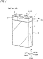
- Fig. 1 and Fig. 2 are schematic configuration views of a package 1 according to embodiment 1.
- Fig. 1 is an external perspective view of a front side of the package 1.
- Fig. 2 is an external perspective view of a back side of the package 1.
- the package 1 is a wrapping body having a box shape and wraps a plurality of cigarette.
- the package 1 is formed by including an inner wrapping box 2 that directly wraps the cigarettes, and an outer wrapping box 3 that wraps the inner wrapping box 2 except for a top closed face 21 of the inner wrapping box 2, and is referred to as a so-called soft package or soft pack.
- the inner wrapping box 2 is formed of, for example, inner wrapping paper having an outer face coated with aluminum foil, and a bottom face and the top closed face 21 thereof form a mouth folded unit 22 by folding the inner wrapping paper.
- the outer wrapping box 3 is formed of outer wrapping paper where a pattern, a product name and the like are printed on an outer face thereof, and wraps the inner wrapping box 2 in such a manner as to cover side faces and the bottom face of the inner wrapping box 2 in a state where the top closed face 21 of the inner wrapping box 2 is exposed.
- a bottom face of the outer wrapping box 3 also forms a mouth folded unit 22 by folding a part of the outer wrapping paper similarly to the top closed face 21 of the inner wrapping box 2.
- reference sign 31 denotes a front face of the outer wrapping box 3
- reference sign 32 denotes a rear face of the outer wrapping box 3.
- reference sign 33a denotes a left side face of the outer wrapping box 3
- reference sign 33b denotes a right side face of the outer wrapping box 3.
- the front face 31 and the rear face 32 of the outer wrapping box 3 are parallel to each other, and are respectively orthogonal to the top closed face 21 of the inner wrapping box 2.
- the top closed face 21 of the inner wrapping box 2, the front face 31 of the outer wrapping box 3, and the rear face 32 of the outer wrapping box 3 respectively correspond to a first face, a second face and a third face according to the present invention.
- a front face side of the package 1 is defined as a "front”
- a back face side is defined as a "rear”.
- respective directions of an up, down, front, rear, left and right of the package 1 are defined as illustrated in Fig. 1 .
- a left-right direction of the package 1 is referred to as a "width direction”
- an up-down direction is referred to as a "height direction”.
- Fig. 1 and Fig. 2 illustrate the respective directions of the up, down, front, rear, left and right.
- the package 1 is sealed by being entirely covered with an exterior film 4 when not opened.
- the exterior film 4 may be a transparent film formed from a material such as polypropylene, cellophane, and polyethylene terephthalate, for example.
- the exterior film 4 is provided with an opening tape (also referred to as a "tear tape") 5.
- the opening tape 5 is a band member that is wound in such a manner as to go around along one circumference surface of the package 1, and is pasted on a back face (inner face) side of the exterior film 4.
- the opening tape 5 is used to tear and open the exterior film 4 by a tip end portion (not illustrated) being pulled by a user (smoker) at a time of opening the package 1.
- Reference sign 4a denotes an upper side portion at an upper side from the opening tape 5, that is, close to the top closed face 21 (mouth folded unit 22), in the exterior film 4.
- Fig. 3 is a view illustrating a state where the package 1 is opened.
- Fig. 3 illustrates a state where the exterior film 4 is torn with the opening tape 5 as a starting point, and the upper side portion 4a of the exterior film 4 is removed.
- the top closed face 21 (mouth folded unit 22) of the inner wrapping box 2 in the package 1 is exposed to outside.
- Reference sign 10 illustrated in Fig. 1 to Fig. 3 denotes a sealing seal.
- the sealing seal 10 has a band shape, and is bonded in such a manner as to straddle the top closed face 21 (mouth folded unit 22) of the inner wrapping box 2, and the front face 31 and the rear face 32 of the outer wrapping box 3.
- the sealing seal 10 crosses a center in a width direction of the top closed face 21 (mouth folded unit 22) of the inner wrapping box 2, and both ends thereof are folded perpendicularly to the front face 31 and the rear face 32 of the outer wrapping box 3.
- the sealing seal 10 seals the top closed face 21 (mouth folded unit 22) of the package 1.
- the exterior film 4 is opened as illustrated in Fig. 3 , after which, one side of the mouth folded unit 22 is cut out with the sealing seal 10 left, of the mouth folded unit 22 formed on the top closed face 21 of the inner wrapping box 2, and an extraction port for cigarettes is formed. Accordingly, the cigarettes wrapped in the inner wrapping box 2 in the package 1 are exposed from the extraction port, and the cigarettes can be extracted.
- the sealing seal 10 in the present embodiment is a double sealing seal in which sealing seals of paper are stacked in two layers.
- Fig. 4 is an exploded view of the sealing seal 10 according to embodiment 1.
- the sealing seal 10 has a lower sealing seal unit 11 that is bonded to the package 1, and an upper seal unit 12 that is stacked on the lower sealing seal unit 11 and is bonded to the lower sealing seal unit.
- the upper seal unit 12 includes a first upper seal unit 13 and a second upper seal unit 14.
- the lower sealing seal unit 11 is a band body having a rectangular shape, and a broken line indicates a folding position.
- Reference sign LB1 illustrated in Fig. 4 denotes a first folding line that is folded in a first edge portion E1 located in a boundary between the front face 31 of the outer wrapping box 3 and the top closed face 21 (mouth folded unit 22) of the inner wrapping box 2.
- Reference sign LB2 denotes a second folding line that is folded in a second edge portion E2 located in a boundary between the rear face 32 of the outer wrapping box 3 and the top closed face 21 (mouth folding unit 22) of the inner wrapping box 2.
- a rectangular region between the first folding line LB1 and the second folding line LB2 will be referred to as a lower first region 111
- a rectangular region between one short side SS1 and the first folding line LB1 will be referred to as a lower second region 112
- a rectangular region between the second folding line LB2 and the other short side SS2 will be referred to as a lower third region 113.
- the lower second region 112 of the lower sealing seal unit 11 is bonded to the front face 31 of the outer wrapping box 3
- the lower first region 111 is bonded to the top closed face 21 (mouth folded unit 22) of the inner wrapping box 2
- the lower third region 113 is bonded to the rear face 32 of the outer wrapping box 3.
- the lower sealing seal unit 11 is bonded to the package 1 in such a manner as to straddle the front face 31 of the outer wrapping box 3, the top closed face 21 (mouth folded unit 22) of the inner wrapping box 2, and the rear face 32 of the outer wrapping box 3.
- FIG. 4 is a top view of the upper seal unit 12 of the sealing seal 10 according to embodiment 1.
- Reference sign 13a denotes a top face of the first upper seal unit 13.
- Reference sign 14a denotes a top face of the second upper seal unit 14.
- the upper seal unit 12 is a band body of paper having a rectangular shape as a whole, and broken lines indicate folding positions.
- Reference sign LU2 is a second folding line that is folded in the second edge portion E2 of the package 1.
- first upper seal unit 13 a rectangular region between the first folding line LU1 and the second folding line LU2 will be referred to as an upper first region 131, and a region between a boundary portion BD from the second upper seal unit 14 in the first upper seal unit 13, and the first folding line LU1 will be referred to as an upper second region 132, and a rectangular region between the second folding line LU2 and a short side SS3 will be referred to as an upper third region 133.
- first upper seal unit 13 and the second upper seal unit 14 in the upper seal unit 12 are locally connected via easy cutting units 15 as illustrated in an enlarged view in Fig. 5 .
- the easy cutting unit 15 is called a so-called nick stop, and can separate the first upper seal unit 13 and the second upper seal unit 14 by being cut (broken) by an external force.
- slits SL are formed except for parts where the easy cutting portions 15 are formed.
- a separation dimension (length dimension of the upper first region 131) between the first folding line LU1 and the second folding line LU2 in the first upper seal unit 13 is equal to a separation dimension (length dimension of the lower first region 111) between the first folding line LB1 and the second folding line LB2 in the lower sealing seal unit 11, and corresponds to a depth dimension of the package 1 (top closed face 21).
- the first upper seal unit 13 may be folded with a slight margin as compared with the lower sealing seal unit 11, and therefore, the separation dimension (length dimension of the upper first region 131) between the first folding line LU1 and the second folding line LU2 in the first upper seal unit 13 may be set to be a slightly larger than the separation dimension (length dimension of the lower first region 111) between the first folding line LB1 and the second folding line LB2 in the lower sealing seal unit 11.
- the upper first region 131 in the first upper seal unit 13 is stacked on the lower first region 111 of the lower sealing seal unit 11 and is glued (bonded) to the lower first region 111.
- the upper second region 132 in the first upper seal unit 13 is stacked on the lower second region 112 in the lower sealing seal unit 11, and is glued to the lower second region 112. Further, the upper third region 133 in the first upper seal unit 13 is stacked on the lower third region 113 in the lower sealing seal unit 11 and is glued to the lower third region 113.
- the separation dimension (length dimension of the upper second region 132) between the boundary portion BD and the first folding line LU1 in the first upper seal unit 13 is smaller as compared with the separation dimension (length dimension of the lower second region 112) between the short side SS1 and the first folding line LB1 in the lower sealing seal unit 11. Accordingly, the upper second region 132 of the first upper seal unit 13 is bonded to the lower second region 112 in such a manner as to cover a part of the lower second region 112 of the lower sealing seal unit 11.
- the second upper seal unit 14 is bonded to the lower second region 112 in such a manner as to cover at least a part of an uncovered region that is not covered with the upper second region 132 of the first upper seal unit 13, in the lower second region 112 in the lower sealing seal unit 11.
- the second upper seal unit 14 is stacked in such a manner as to cover a whole (all) of the uncovered region in the lower second region 112 of the lower sealing seal unit 11.
- the separation dimension (length dimension of the upper third region 133) between the short side SS3 and the second folding line LU2 in the first upper seal unit 13 is equal to the separation dimension (length dimension of the lower third region 113) between the short side SS2 and the second folding line LB2 in the lower sealing seal unit 11.
- the separation dimension (length dimension of the upper third region 133) between SS3 and the second folding line LU2 may be set to be slightly larger than the separation dimension (length dimension of the lower third region 113) between the short side SS2 and the second folding line LB2 in the lower sealing seal unit 11.
- a picking tab 16 is provided at a tip end portion located on a boundary portion BD side from the second upper seal unit 14.
- the picking tab 16 is a tongue that protrudes from other parts to be easily picked when a user (smoker) peels the upper seal unit 12 (first upper seal unit 13) from the lower sealing seal unit 11.
- the picking tab 16 is provided to protrude to an opposite direction (opposite side) to the first folding line LU1 from a tip end portion of the upper second region 132 in the first upper seal unit 13.
- the picking tab 16 has a trapezoidal shape, and a shape thereof is defined by a tab upper side 161, a tab first oblique side 162, and a tab second oblique side 163.
- the tab upper side 161 of the picking tab 16 is parallel to the first folding line LU1, and the tab first oblique side 162 and the tab second oblique side 163 incline to the tab upper side 161.
- the picking tab 16 of the first upper seal unit 13 is locally connected to the second upper seal unit 14 via the easy cutting unit 15.
- a recessed unit 17 in a trapezoidal shape that receives the picking tab 16 is formed on the boundary portion BD side in the second upper seal unit 14.
- the recessed unit 17 has a shape thereof defined by a recessed unit upper side 171, a recessed unit first oblique side 172, and a recessed unit second oblique side 173.
- the recessed unit upper side 171, the recessed unit first oblique side 172, and the recessed unit second oblique side 173 of the recessed unit 17 are respectively disposed to face the tab upper side 161, the tab first oblique side 162, and the tab second oblique side 163 of the picking tab 16.
- the easy cutting portion 15 locally connects the tab first oblique side 162 and the tab second oblique side 163 of the picking tab 16 and the recessed unit first oblique side 172 and the recessed unit second oblique side 173 on a recessed unit 17 side that face the tab first oblique side 162 and the tab second oblique side 163. Further, as illustrated in Fig.
- the easy cutting portion 15 extends along an oblique direction to the first folding line LU1 in the first upper seal unit 13.
- the easy cutting portion 15 is provided in each of the tab first oblique side 162 and the tab second oblique side 163 of the picking tab 16, but a number of easy cutting portions 15 is not especially limited.
- a plurality of easy cutting portions 15 may be provided in each of the tab first oblique side 162 and the tab second oblique side 163.
- the easy cutting portion 15 may be provided in only either one of the tab first oblique side 162 and the tab second oblique side 163.
- the boundary portion BD of the first upper seal unit 13 and the second upper seal unit 14 regions sandwiched by the slits SL are formed as the easy cutting portions 15, but the easy cutting portions 15 may be formed by applying half-cut processing along the boundary portion BD.
- a pair of slits 18a and 18b are provided in a vicinity of the second folding line LU2.
- the slits 18a and 18b penetrate through the upper third region 133 in the first upper seal unit 13 in a thickness direction.
- the slits 18a and 18b are provided to extend parallel to the second folding line LU2.
- the two slits 18a and 18b are provided in the upper third region 133, but a number of the slits is not especially limited.
- Reference sign BP illustrated in Fig. 4 denotes a gluing part of the upper seal unit 12 (the first upper seal unit 13, the second upper seal unit 14) to the lower sealing seal unit 11.
- an adhesive glue is applied to points, and thereby the upper seal unit 12 (the first upper seal unit 13, the second upper seal unit 14) is bonded to the lower sealing seal unit 11 to be peelable.
- the picking tab 16 of the upper second region 132 in the first upper seal unit 13 is in an unbonded state to the lower second region 112 of the lower sealing seal unit 11.
- Fig. 6 is a view illustrating a back face 13b of the first upper seal unit 13 of the sealing seal 10 according to embodiment 1.
- the back face 13b of the first upper seal unit 13 is a bonding face that is bonded to a top face of the lower sealing seal unit 11.
- information codes (not illustrated) coding information concerning a campaign, information on URL and an electronic mail address for accessing a campaign site are printed.
- the information code is preferably printed on the back face 13b corresponding to the upper first region 131 having a largest area of the first upper seal unit 13.
- the information code may be a QR code (registered trademark) that is a kind of a two-dimensional code, for example. Further, instead of the two-dimensional code, a one-dimensional barcode may be printed on the back face 13b of the first upper seal unit 13.
- the sealing seal 10 and the top closed face 21 (mouth folded unit 22) of the package 1 are exposed as illustrated in Fig. 3 by the upper side unit 4a of the opening tape 5 in the exterior film 4 being removed.
- the sealing seal 10 (the lower sealing seal unit 11) is bonded in such a manner as to straddle the front face 31 of the outer wrapping box 3, the top closed face 21 (mouth folded unit 22) of the inner wrapping box 2 and the rear face 32 of the outer wrapping box 3.
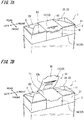
- the picking tab 16 is provided at the tip end portion of the upper second region 132 in the first upper seal unit 13, and therefore, the user (smoker) can easily peel the first upper seal unit 13 from the lower sealing seal unit 11 as illustrated in Fig. 7A and Fig. 7B by picking the picking tab 16 and pulling up the picking tab 16.
- the package 1 including the sealing seal 10 in the present embodiment can be manufactured by customizing an existing package packing machine, and is highly useful as a tool that can add product information without enormous investment in machinery and equipment. Further, the package 1 can be manufactured by replacing an ordinary sealing seal with the sealing seal 10 according to the present embodiment, and therefore reduction in manufacture efficiency of the package 1 by a packing machine can also be reduced.
- a linear picking edge portion E3 is formed by the tab upper side 161 in the picking tab 16 in the first upper seal unit 13, so that a finger of the user (smoker) is more easily caught by the picking tab 16 (picking edge portion E3), and the first upper seal unit 13 can be more easily peeled from the lower sealing seal unit 11.
- a trapezoidal shape can be preferably cited. Note that in the boundary portion BD from the second upper seal unit 14 in the upper second region 132 of the first upper seal unit 13, edge portions that are located at both sides of the picking tab 16, that is, edge portions located at roots of the picking tab 16 are referred to as "tab base end edge portions E4".
- the picking edge portion E3 and the tab base end edge portion E4 are parallel to the first folding line LU1 and the first edge portion E1 in the first upper seal unit 13.
- the lower second region 112 of the lower sealing seal unit 11 is folded in an orthogonal direction from the lower first region 111 with the first edge portion E1 as a boundary and is bonded to the front face 31 of the outer wrapping box 3. Further, the upper second region 132 of the first upper seal unit 13 is folded in an orthogonal direction from the upper first region 131 to be along the lower second region 112 of the lower sealing seal unit 11 with the first edge portion E1 as a boundary.
- the upper second region 132 of the first upper seal unit 13 is folded in the orthogonal direction from the upper first region 131, whereby a restoration force can be caused to act in a direction to peel the upper second region 132 of the first upper seal unit 13 from the lower second region 112 of the lower sealing seal unit 11.
- the picking tab 16 is provided to protrude toward an opposite direction (opposite side) to the first edge portion E1, from the tip end portion of the upper second region 132 in the first upper seal unit 13.
- the picking tab 16 is provided close to the first edge portion E1 of the package 1. Accordingly, the restoration force of the upper second region 132 acting in the direction to turn up the picking tab 16 can be further increased.
- a separation dimension distance hereinafter, referred to as a "first separation distance" D1 (refer to Fig.
- first folding line LU1 between a root portion of the picking tab 16, that is, the tab base end edge portion E4 and the first edge portion E1 (first folding line LU1) is preferably set in a range of 0 mm or more and 4 mm or less, is more preferably set in a range of 0 mm or more and 3 mm or less, and is especially preferably set in a range of 0 mm or more and 2 mm or less.
- first separation distance D1 4 mm or less By making the first separation distance D1 4 mm or less, a preferable repulsive force is obtained in the upper second region 132 of the first upper seal unit 13, and by making the first separation distance D1 3 mm or less, a more preferable repulsive force is obtained. Further, by making the first separation distance D1 2 mm or less, an optimal state for turning up the first upper seal unit 13 is brought about.
- a nick portion length L1 (refer to the partially enlarged vie in Fig. 5 ) of the easy cutting unit 15
- the nick portion is likely to be cut during manufacture when the nick length L1 is less than 0.3 mm, and when the nick length L1 becomes more than 0.7 mm, paper is likely to be cut in an undesired portion (portion except for the nick) when the user picks the package 1 after manufacture of the package 1. Therefore, setting the nick length L1 in a range of 0.3 to 0.7 mm is preferable, and setting at 0.5 mm is optimal.
- the second separation distance D2 is preferably set within a range of 1 mm or more and 3 mm or less.
- the picking tab tip end width L2 is preferably set at a dimension of 5 mm or more from a viewpoint of picking easiness of the picking edge portion E3.
- a width (hereinafter, referred to as a "picking tab base end width") L3 (refer to the partially enlarged view of Fig. 5 ) of the tab base end edge portion E4 in the picking tab 16 will be mentioned.
- the picking tab base end widths L3 of the respective tab base end edge portions E4 formed on both sides of the picking tab 16 is preferably set at a width of 1 mm or more from a viewpoint of allowing a precision error in manufacture of the sealing seal 10.
- Fig. 8A is a view illustrating a sheet material S1 for forming the sealing seal 10 of a specification of forming the tab base end edge portions E4 on both sides of the picking tab 16.
- FIG. 8B is a view illustrating a sheet material S2 for forming the sealing seal 10 of a specification of not forming the tab base end edge portions E4 on both sides of the picking tab 16.
- Reference sign CLp illustrated in Figs. 8A and 8B denotes a design cutting line
- reference sign CLa denotes an actual cutting position.
- the sheet materials S1 and S2 are cut along the design cutting lines CLp in a manufacture process, and thereby are separated to individual sealing seals 10.
- Figs. 8A and 8B illustrate cases in which when the individual sealing seals 10 are cut out from the sheet materials S1 and S2, the individual seals 10 are cut along the actual cutting positions CLa that are deviated from the design cutting lines CLp.
- the tab base end edge portions E4 are formed on both sides of the picking tab 16, whereby even when the actual cutting position CLa is somewhat deviated from the design cutting line CLp, the aforementioned picking tab base end width L3 is only slightly different from a design value and is not noticeable, and an error of the cutting position of the sealing seal 10 in the manufacture process is allowed.
- the tab base end edge portions E4 are not formed on both sides of the picking tab 16, and the picking tab base end width L3 is zero. Accordingly, when the actual cutting position CLa deviates from the design cutting line CLp, shapes at one end side and the other end side in the width direction of the sealing seal 10 become different and noticeable, in the sealing seal 10 after being cut out from the sheet material S2. In other words, an error of the cutting position of the sealing seal 10 in the manufacture process is not allowed, and there is a fear that the sealing seal 10 cannot be used as a product, and cannot help being discarded. There is no particular demerit in increasing the picking tab base end width L3 of the tab base end edge portion E4, but the picking tab base end width L3 can be decided in relation to a total width dimension of the sealing seal 10, the picking tab tip end width L2 and the like.
- an angle (hereinafter, referred to as an "oblique side inclination angle ") ⁇ (refer to Fig. 5 ) formed by the tab first oblique side 162 (tab second oblique side 163) connecting the picking edge portion E3 and the tab base end edge portion E4 in the picking tab 16, and the picking edge portion E3 is preferably 90° or more.
- An upper limit angle of the oblique side inclination angle ⁇ in the picking tab 16 can be properly calculated based on respective dimensions of the entire width of the sealing seal 10, the picking tab tip end width L2, the picking tab base end width L3, the second separation distance D2 and the like.
- 20 mm is often adopted as standard. Therefore, when the entire width of the sealing seal 10 is set as 20 mm, the picking tab tip end width L2 is set as 5 mm, the picking tab base end widths L3 of the respective tab base end edge portions E4 on both sides of the picking tab 16 are set as 1 mm, and the second separation distance D2 is set as 2 mm, the oblique side inclination angle ⁇ is substantially 163°.
- the oblique side inclination angle ⁇ of the picking tab 16 may be set in a range of 90° or more and 163° or less, and by setting the oblique inclination angle ⁇ in the range like this, it is possible to balance the difficulty of tearing and picking easiness of the picking tab 16.
- the oblique side inclination angle ⁇ of the picking tab 16 is more preferably set in a range of 105° or more and 163° or less.
- the oblique side inclination angle ⁇ of the picking tab 16 is especially preferably set in a range (range of 135 ⁇ 5°) of 130° or more and 140° or less, and balance of tearing difficulty and picking easiness is especially excellent. It goes without saying that the entire width of the sealing seal 10 is not limited to 20 mm.
- the picking tab 16 of the first upper seal unit 13 is in a state of being unbonded to the lower sealing seal unit 11, and the picking tab 16 is locally connected to the second upper seal unit 14 adjacent to the picking tab 16 via the easy cutting units 15.
- the easy cutting unit 15 can be easily cut by picking and pulling up the picking tab 16, and the first upper seal unit 13 can be easily peeled off from the lower sealing seal unit 11 in a state where the second upper seal unit 14 is kept in a state of being bonded to the lower sealing seal unit 11.
- the picking tab 16 in the first upper seal unit 13 is formed into a trapezoidal shape, and the trapezoidal recessed unit 17 that is complementary to the picking tab 16 is formed at the tip end side of the second upper seal unit 14, and thereby the tab first oblique side 162 and the tab second oblique side 163 of the picking tab 16 and the recessed unit first oblique side 172 and the recessed unit second oblique side 173 that face the tab first oblique side 162 and the tab second oblique side 163 are connected by the easy cutting units 15.
- the easy cutting units 15 in the first upper seal unit 13 can be extended along the oblique direction to the first edge portion E1.
- a component force of a tensile force that acts when the picking tab 16 is picked up acts in a direction to tear the easy cutting unit 15, so that it is possible to tear the easy cutting unit 15 preferably and to restrain a portion except for the easy cutting unit 15 in the first upper seal unit 13, for example, the region where the information code is printed on the back face 13b, from being torn.
- the easy cutting unit 15 in the first upper seal unit 13 may be extended along a perpendicular direction to the first edge portion E1, and by specifying the extending direction of the easy cutting unit 15 in this way, only the easy cutting unit 15 can be preferably cut when the picking tab 16 is picked up.
- the slits 18a and 18b are provided in the upper third region 133 in the first upper seal unit 13, so that the repulsive force of paper caused by pasting the upper third region 133 in the first upper seal unit 13 and the lower third region 113 of the lower sealing seal unit 11 is reduced, and folding can be performed smoothly. Further, a tensile force to the easy cutting unit 15 in the front face side of the package 1 is relaxed, and quality can be stabilized.
- the slits 18a and 18b may be formed as such microscopic incisions that cannot be recognized visually with naked eyes, and thereby reduction in appearance quality of the package 1 can be restrained.
- the slits 18a and 18b in the upper third region 133 of the first upper seal unit 13 are preferably provided in a vicinity of the second folding line LU2 (second edge portion E2). Further, the slits 18a and 18b may be formed in the upper first region 131 of the first upper seal unit 13 if only the slits 18a and 18b are in the vicinity of the second folding line LU2 (second edge portion E2), and the repulsive force of the paper caused by pasting the first upper seal unit 13 onto the lower sealing seal unit 11 can be reduced.
- a separation distance hereinafter, referred to as a "third separation distance" D3 (refer to Fig. 5 ) to the slits 18a and 18b from the second folding line LU2 (second edge portion E2) in the first upper seal unit 13 is preferably set in a range of 0 mm or more and 5 mm or less.
- the third separation distance D3 is smaller, an effect of relaxing the repulsive force of the paper caused by pasting the upper third region 133 in the first upper seal unit 13 and the lower third region 113 of the lower sealing seal unit 11 can be increased.
- the repulsive force of the paper described above can be reduced preferably.
- the third separation distance D3 is 0 mm, it means that the slits 18a and 18b are formed on the second folding line LU2 in the first upper seal unit 13.
- the third separation distance D3 is smaller, the effect of relaxing the repulsive force of the paper can be increased as described above, but on the other hand, when a consumer picks the picking tab 16 and turns the first upper seal unit 13, a break may easily occur to the first upper seal unit 13 in the positions of the slits 18a and 18b.
- the above described third separation distance D3 is especially preferably set in a range of 1.5 mm or more and 3.0 mm or less.
- the slits 18a and 18b may be provided on the top face side (the upper first region 131) of the package 1, or may be provided on a back face side (the upper third region 133) of the package 1.
- the slits 18a and 18b are provided to extend parallel to the second folding line LU2, and therefore, the repulsive force (restoration force) by folding of the upper third region 133 in the first upper seal unit 13 can be relaxed more preferably.
- the inner wrapping box 2 and the outer wrapping box 3 are sealed by being covered with the exterior film 4, and the picking tab 16 in the first upper seal unit 13 of the sealing seal 10 is disposed above the opening tape 5 provided on the exterior film 4.
- the picking tab 16 of the first upper seal unit 13 can be exposed to outside, and therefore the picking tab 16 can be easily picked.
- the package 1 remains to be sealed, the entire package 1 is covered with the exterior film 4, and therefore the first upper seal unit 13 of the sealing seal 10 is not peeled illicitly. In other words, it is possible to regulate a fraudulent act such as a person who has not purchased the package 1 (tobacco product) properly peels the first upper seal unit 13 of the sealing seal 10 and applies for a campaign, for example.
- the shape of the picking tab 16 in the sealing seal 10 is trapezoidal, but other shapes may be adopted.
- Figs. 9A to 9C illustrate modified examples of the picking tab 16 in the sealing seal 10.
- the picking tab 16 has a rectangular shape instead of a trapezoidal shape.
- the picking edge portion E3 and the tab base end edge portion E4 are connected by vertical edge portions E5 orthogonal to the picking edge portion E3 and the tab base end edge portion E4.
- the picking tab 16 has an arc-shaped picking edge portion E3', and the tab base end edge portions E4 are respectively connected to both ends of the picking edge portion E3'.
- the linear picking edge portion E3 and the tab base end edge portions E4 are connected via arc edge portions E6 in arc shapes.
- the lower sealing seal unit 11 and the upper seal unit 12 in the sealing seal 10 are made of paper is explained as an example, the lower sealing seal unit 11 and the upper seal unit 12 may be made of a polymeric material.
- the sealing seal 10 As the polymeric material forming the sealing seal 10, PE (polyethylene), PP (polypropylene), PET (polyethylene terephthalate) and the like are illustrated. Further, the sealing seal 10 may be formed of bonded paper of the above described polymeric material and paper, or bonded paper of metal foil and paper. Further, in a paste (adhesive agent) that is used in bonding of the lower sealing seal unit 11 and the upper seal unit 12 in the sealing seal 10, for example, an ethylene vinyl acetate resin may be used for a main material, for example.
- a paste adhesive agent
- an ethylene vinyl acetate resin may be used for a main material, for example.
- paste of an ethylene vinyl acetate resin is preferably used, but the paste is not limited to this.
- the case of wrapping cigarettes in the package 1 is explained as an example, but an object to be wrapped is not especially limited.
- other objects to be wrapped in the package 1 may be cigars, cigarillos, smokeless cigarettes such as snus, and electronic cigarettes.
- an object to be wrapped that is not a tobacco product may be wrapped with the package 1 without being limited to the tobacco products as described above.
Landscapes
- Engineering & Computer Science (AREA)
- Mechanical Engineering (AREA)
- Packages (AREA)
- Packaging Of Annular Or Rod-Shaped Articles, Wearing Apparel, Cassettes, Or The Like (AREA)
- Cartons (AREA)
Abstract
Description
- The present invention relates to a double sealing seal and a package.
- Tobacco products such as cigarettes are usually wrapped in a wrapping body for each predetermined number of tobacco products. As the wrapping body like this, the wrapping body formed by an inner wrapping paper such as an aluminum foil sheet, and an outer wrapping paper covering the inner wrapping paper is well known, and is called individual packaging as it is called. As the outer wrapping paper, there are known the outer wrapping paper formed of thin paper called a soft pack or a soft package, and the outer wrapping paper formed by assembling a paperboard into a box shape that is called a hard pack, a hard package or a box.
- A soft package for cigarettes usually wraps a plurality of cigarettes with an inner wrapping paper, and further wraps side faces and a bottom face of the inner wrapping paper with an outer wrapping paper. A sealing sheet is glued so as to straddle part of a mouth folded unit formed by folding the inner wrapping papers onto each other and the outer wrapping paper. When a cigarette is taken out, the inner wrapping paper of either one of the mouth folded units formed at both sides of the sealing sheet is cut out to form an extraction port (opening portion), and thereby the cigarette can be taken out.
- Here, a soft package in which sealing sheets are stacked in two layers is known (refer to
Patent document 1, for example). In the package indicated byPatent document 1, a second sealing sheet is stacked on a first sealing sheet that is glued so as to straddle part of a mouth folded unit and an outer wrapping paper, and the second sealing sheet is glued to the first sealing sheet to be attachable and detachable by an adhesive agent having attachability and detachability. According to the package, after the opening portion for extracting a cigarette is formed in a part of the mouth folded unit, the second sealing sheet glued onto the first sealing sheet attachably and detachably is removed, and the opening portion can be covered with the second sealing sheet, so that prevention of falling-off of the cigarettes from the opening portion, moisture prevention for the cigarettes in the package, prevention of fragrance dispersion and the like can be achieved. - [Patent document 1] Japanese Patent Laid-Open No.
7-203938 - However, in the double sealing sheet (seal) in the prior art has the problem that an upper layer portion is difficult to remove from a lower layer portion.
- The present invention is made in the light of the circumstances as above, and has an object to provide a double sealing seal in which an upper seal unit is peeled from a lower seal unit more easily as compared with the prior art, and a package including the double sealing seal.
- In the present invention, in order to solve the above described problem, a picking tab for picking when an upper seal unit is peeled from a lower sealing seal unit that is bonded to a wrapping unit is provided in an upper seal unit of a double sealing seal attached to the wrapping unit.
- In more detail, a package according to the present invention includes a wrapping unit that wraps an object to be wrapped, and a double sealing seal that is attached to the wrapping unit, wherein the double sealing seal includes a lower sealing seal unit that is bonded to the wrapping unit, an upper seal unit that is stacked on the lower sealing seal unit and is bonded to the lower sealing seal unit, and a picking tab that is provided at the upper seal unit.
- Further, the present invention is a double sealing seal that is attached to a wrapping unit that wraps an object to be wrapped, and includes a lower sealing seal unit that is bonded to the wrapping unit, an upper seal unit that is stacked on the lower sealing seal unit and is bonded to the lower sealing seal unit, and a picking tab that is provided at the upper seal unit.
- According to the present invention, the picking tab is provided at the upper seal unit of the double sealing seal, and therefore, the upper seal unit can be easily peeled from the lower sealing seal unit that is bonded to the wrapping unit with the picking tab as a starting point.
- Further, in the double sealing seal according to the present invention, the picking tab may include a linear picking edge portion.
- Further, in the double sealing seal according to the present invention, the picking tab may have a trapezoidal shape.
- Further, in the package according to the present invention, the wrapping unit may have a box shape, and may be configured by including a first face and a second face that are orthogonal to each other, the lower sealing seal unit may be a band body including a lower first region that is bonded to the first face, and a lower second region that is bonded to the second face, and is bonded to the wrapping unit to straddle the first face and the second face, the upper seal unit may include an upper first region that is stacked on the lower first region and an upper second region that is stacked on the lower second region, the upper second region may be folded in an orthogonal direction from the upper first region to be along the lower second region with a first edge portion located between the first face and the second face as a boundary, and the picking tab may be provided to protrude to an opposite direction to the first edge portion from a tip end side of the upper second region.
- Further, in the double sealing seal, the picking tab may be provided close to the first edge portion. In this case, a first separation distance at which a linear tab base end edge portion formed at a root of the picking tab in the first upper seal unit and the first edge portion are separated may be set in a range of 0 mm or more and 4 mm or less. Further, a second separation distance at which a linear picking edge portion formed at a tip end side of the picking tab and the tab base end edge portion are separated may be set in a range of 1 mm or more and 3 mm or less.
- Further, in the double sealing seal, the upper second region in the upper seal unit may cover a part of the lower second region in the lower sealing seal unit, in at least a part of an uncovered region that is not covered with the upper second region, in the lower second region, a second upper seal unit may be bonded to the lower second region to be adjacent to a tip end portion of the upper seal unit where the picking tab is formed, the picking tab in the upper second region may be in an unbonded state to the lower second region, and the picking tab and the second upper seal unit may be locally connected via an easy cutting unit, and when the upper seal unit is peeled from the lower sealing seal unit via the picking tab, the easy cutting unit is cut, and thereby the second upper seal unit may be kept in a state of being bonded to the lower sealing seal unit.
- Here, in the double sealing seal, the easy cutting unit may extend along an oblique direction or a perpendicular direction to the first edge portion.
- Further, in the double sealing seal, the picking tab may have a trapezoidal shape, in a boundary portion from a tip end side of the upper seal unit, in the second upper seal unit, a trapezoidal recessed unit that stores the picking tab may be formed, and the easy cutting unit may locally connect an oblique side of the picking tab and an oblique side at the recessed unit side facing the oblique side of the tab.
- Further, in the double sealing seal, the second upper seal unit may be stacked on the uncovered region to cover a whole of the uncovered region in the lower second region.
- Further, in the double sealing seal, the wrapping unit may include a third face that is orthogonal to the first face and is parallel to the second face, the lower sealing seal unit may further include a lower third region that is bonded to the third face, and is bonded to the wrapping unit to straddle the first face, the second face and the third face, the upper seal unit may further include an upper third region that is stacked on the lower third region, and a slit may be provided in the upper third region.
- Further, in the double sealing seal, the slit in the upper third region may be provided to extend parallel to a second edge portion that is located between the first face and the third face.
- Further, in the double sealing seal, the slit in the upper third region may be provided close to the second edge portion.
- Further, in the package according to the present invention, the wrapping unit may be sealed by an exterior film, the exterior film may be provided with an opening tape that is wound on the wrapping unit to go around the wrapping unit, and the picking tab may be disposed above the opening tape.
- Further, in the package according to the present invention, a tobacco product may be wrapped in the wrapping unit.
- Means for solving the problem in the present invention can be adopted by being combined as much as possible.
- According to the present invention, the double sealing seal in which the upper seal unit is peeled from the lower seal unit more easily as compared with the prior art, and the package including the double sealing seal can be provided.
-
- [
Fig. 1] Fig. 1 is a schematic configuration view of a package according toembodiment 1. - [
Fig. 2] Fig. 2 is a schematic configuration view of the package according toembodiment 1. - [
Fig.3] Fig. 3 is a view illustrating a state where the package according toembodiment 1 is unsealed. - [
Fig. 4] Fig. 4 is an exploded view of a sealing seal according toembodiment 1. - [
Fig. 5] Fig. 5 is a top view of an upper seal unit of the sealing seal according toembodiment 1. - [
Fig. 6] Fig. 6 is a back face of a first upper seal unit of the sealing seal according toembodiment 1. - [
Fig. 7A] Fig. 7A is a view illustrating a situation where the first upper seal unit is peeled off from a lower sealing seal unit in the sealing seal according toembodiment 1. - [
Fig. 7B] Fig. 7B is a view illustrating the situation where the first upper seal unit is peeled off from the lower sealing seal unit in the sealing seal according toembodiment 1. - [
Fig. 8A] Fig. 8A is a view illustrating a sheet material for forming a sealing seal of a specification of forming tab base end edge portions on both sides of a picking tab. - [
Fig. 8B] Fig. 8B is a view illustrating a sheet material for forming a sealing seal of a specification of not forming tab base end edge portions on both sides of a picking tab. - [
Fig. 9A] Fig. 9A illustrates a modified example of the picking tab in the sealing seal. - [
Fig. 9B] Fig. 9B illustrates a modified example of the picking tab in the sealing seal. - [
Fig. 9C] Fig. 9C illustrates a modified example of the picking tab in the sealing seal. - Here, an embodiment of a double sealing seal and a package according to the present invention will be described based on the drawings. Sizes, materials and shapes of components, relative dispositions thereof and the like described in the present embodiment do not intend to limit a technical range of the invention to only them, unless otherwise specified.
-
Fig. 1 andFig. 2 are schematic configuration views of apackage 1 according toembodiment 1.Fig. 1 is an external perspective view of a front side of thepackage 1.Fig. 2 is an external perspective view of a back side of thepackage 1. Thepackage 1 is a wrapping body having a box shape and wraps a plurality of cigarette. Thepackage 1 is formed by including aninner wrapping box 2 that directly wraps the cigarettes, and anouter wrapping box 3 that wraps theinner wrapping box 2 except for a top closed face 21 of theinner wrapping box 2, and is referred to as a so-called soft package or soft pack. - The
inner wrapping box 2 is formed of, for example, inner wrapping paper having an outer face coated with aluminum foil, and a bottom face and the top closed face 21 thereof form a mouth folded unit 22 by folding the inner wrapping paper. Theouter wrapping box 3 is formed of outer wrapping paper where a pattern, a product name and the like are printed on an outer face thereof, and wraps theinner wrapping box 2 in such a manner as to cover side faces and the bottom face of theinner wrapping box 2 in a state where the top closed face 21 of theinner wrapping box 2 is exposed. A bottom face of theouter wrapping box 3 also forms a mouth folded unit 22 by folding a part of the outer wrapping paper similarly to the top closed face 21 of theinner wrapping box 2. Here,reference sign 31 denotes a front face of theouter wrapping box 3, andreference sign 32 denotes a rear face of theouter wrapping box 3. Further,reference sign 33a denotes a left side face of theouter wrapping box 3, andreference sign 33b denotes a right side face of theouter wrapping box 3. Thefront face 31 and therear face 32 of theouter wrapping box 3 are parallel to each other, and are respectively orthogonal to the top closed face 21 of theinner wrapping box 2. In the present embodiment, the top closed face 21 of theinner wrapping box 2, thefront face 31 of theouter wrapping box 3, and therear face 32 of theouter wrapping box 3 respectively correspond to a first face, a second face and a third face according to the present invention. Further, theinner wrapping box 2 and theouter wrapping box 3 in the present embodiment correspond to a wrapping unit in the present invention. Hereinafter, in the present specification, a front face side of thepackage 1 is defined as a "front", and a back face side is defined as a "rear". Further, respective directions of an up, down, front, rear, left and right of thepackage 1 are defined as illustrated inFig. 1 . A left-right direction of thepackage 1 is referred to as a "width direction", and an up-down direction is referred to as a "height direction".Fig. 1 andFig. 2 illustrate the respective directions of the up, down, front, rear, left and right. - As illustrated in
Fig. 1 andFig. 2 , thepackage 1 is sealed by being entirely covered with an exterior film 4 when not opened. The exterior film 4 may be a transparent film formed from a material such as polypropylene, cellophane, and polyethylene terephthalate, for example. The exterior film 4 is provided with an opening tape (also referred to as a "tear tape") 5. Theopening tape 5 is a band member that is wound in such a manner as to go around along one circumference surface of thepackage 1, and is pasted on a back face (inner face) side of the exterior film 4. Theopening tape 5 is used to tear and open the exterior film 4 by a tip end portion (not illustrated) being pulled by a user (smoker) at a time of opening thepackage 1.Reference sign 4a denotes an upper side portion at an upper side from theopening tape 5, that is, close to the top closed face 21 (mouth folded unit 22), in the exterior film 4.Fig. 3 is a view illustrating a state where thepackage 1 is opened.Fig. 3 illustrates a state where the exterior film 4 is torn with theopening tape 5 as a starting point, and theupper side portion 4a of the exterior film 4 is removed. In the state illustrated inFig. 3 , the top closed face 21 (mouth folded unit 22) of theinner wrapping box 2 in thepackage 1 is exposed to outside. -
Reference sign 10 illustrated inFig. 1 to Fig. 3 denotes a sealing seal. The sealingseal 10 has a band shape, and is bonded in such a manner as to straddle the top closed face 21 (mouth folded unit 22) of theinner wrapping box 2, and thefront face 31 and therear face 32 of theouter wrapping box 3. The sealingseal 10 crosses a center in a width direction of the top closed face 21 (mouth folded unit 22) of theinner wrapping box 2, and both ends thereof are folded perpendicularly to thefront face 31 and therear face 32 of theouter wrapping box 3. The sealingseal 10 seals the top closed face 21 (mouth folded unit 22) of thepackage 1. - In order to extract a cigarette from the
package 1, the exterior film 4 is opened as illustrated inFig. 3 , after which, one side of the mouth folded unit 22 is cut out with the sealingseal 10 left, of the mouth folded unit 22 formed on the top closed face 21 of theinner wrapping box 2, and an extraction port for cigarettes is formed. Accordingly, the cigarettes wrapped in theinner wrapping box 2 in thepackage 1 are exposed from the extraction port, and the cigarettes can be extracted. - The sealing
seal 10 in the present embodiment is a double sealing seal in which sealing seals of paper are stacked in two layers. Hereinafter, a detailed structure of the sealingseal 10 will be described.Fig. 4 is an exploded view of the sealingseal 10 according toembodiment 1. The sealingseal 10 has a lowersealing seal unit 11 that is bonded to thepackage 1, and anupper seal unit 12 that is stacked on the lowersealing seal unit 11 and is bonded to the lower sealing seal unit. Theupper seal unit 12 includes a firstupper seal unit 13 and a secondupper seal unit 14. - As illustrated in
Fig. 4 , the lowersealing seal unit 11 is a band body having a rectangular shape, and a broken line indicates a folding position. Reference sign LB1 illustrated inFig. 4 denotes a first folding line that is folded in a first edge portion E1 located in a boundary between thefront face 31 of theouter wrapping box 3 and the top closed face 21 (mouth folded unit 22) of theinner wrapping box 2. Reference sign LB2 denotes a second folding line that is folded in a second edge portion E2 located in a boundary between therear face 32 of theouter wrapping box 3 and the top closed face 21 (mouth folding unit 22) of theinner wrapping box 2. - Hereinafter, in the lower
sealing seal unit 11, a rectangular region between the first folding line LB1 and the second folding line LB2 will be referred to as a lowerfirst region 111, a rectangular region between one short side SS1 and the first folding line LB1 will be referred to as a lowersecond region 112, and a rectangular region between the second folding line LB2 and the other short side SS2 will be referred to as a lowerthird region 113. The lowersecond region 112 of the lowersealing seal unit 11 is bonded to thefront face 31 of theouter wrapping box 3, the lowerfirst region 111 is bonded to the top closed face 21 (mouth folded unit 22) of theinner wrapping box 2, and the lowerthird region 113 is bonded to therear face 32 of theouter wrapping box 3. In other words, as illustrated inFig. 3 , the lowersealing seal unit 11 is bonded to thepackage 1 in such a manner as to straddle thefront face 31 of theouter wrapping box 3, the top closed face 21 (mouth folded unit 22) of theinner wrapping box 2, and therear face 32 of theouter wrapping box 3. - Next, details of the
upper seal unit 12 of the sealingseal 10 will be described. As illustrated inFig. 4 , the upper seal unit 12 (a combination of the firstupper seal unit 13 and the second upper seal unit 14) is substantially congruent with the lowersealing seal unit 11 as a whole.Fig. 5 is a top view of theupper seal unit 12 of the sealingseal 10 according toembodiment 1.Reference sign 13a denotes a top face of the firstupper seal unit 13.Reference sign 14a denotes a top face of the secondupper seal unit 14. Theupper seal unit 12 is a band body of paper having a rectangular shape as a whole, and broken lines indicate folding positions. In the firstupper seal unit 13, reference sign LU1 illustrated inFig. 5 is a first folding line that is folded in the first edge portion E1 of thepackage 1. Reference sign LU2 is a second folding line that is folded in the second edge portion E2 of thepackage 1. Hereinafter, in the firstupper seal unit 13, a rectangular region between the first folding line LU1 and the second folding line LU2 will be referred to as an upperfirst region 131, and a region between a boundary portion BD from the secondupper seal unit 14 in the firstupper seal unit 13, and the first folding line LU1 will be referred to as an uppersecond region 132, and a rectangular region between the second folding line LU2 and a short side SS3 will be referred to as an upperthird region 133. - Here, the first
upper seal unit 13 and the secondupper seal unit 14 in theupper seal unit 12 are locally connected viaeasy cutting units 15 as illustrated in an enlarged view inFig. 5 . Theeasy cutting unit 15 is called a so-called nick stop, and can separate the firstupper seal unit 13 and the secondupper seal unit 14 by being cut (broken) by an external force. In the boundary portion BD between the firstupper seal unit 13 and the secondupper seal unit 14, slits SL are formed except for parts where theeasy cutting portions 15 are formed. - Here, a separation dimension (length dimension of the upper first region 131) between the first folding line LU1 and the second folding line LU2 in the first
upper seal unit 13 is equal to a separation dimension (length dimension of the lower first region 111) between the first folding line LB1 and the second folding line LB2 in the lowersealing seal unit 11, and corresponds to a depth dimension of the package 1 (top closed face 21). However, due to a thickness of paper, the firstupper seal unit 13 may be folded with a slight margin as compared with the lowersealing seal unit 11, and therefore, the separation dimension (length dimension of the upper first region 131) between the first folding line LU1 and the second folding line LU2 in the firstupper seal unit 13 may be set to be a slightly larger than the separation dimension (length dimension of the lower first region 111) between the first folding line LB1 and the second folding line LB2 in the lowersealing seal unit 11. The upperfirst region 131 in the firstupper seal unit 13 is stacked on the lowerfirst region 111 of the lowersealing seal unit 11 and is glued (bonded) to the lowerfirst region 111. Further, the uppersecond region 132 in the firstupper seal unit 13 is stacked on the lowersecond region 112 in the lowersealing seal unit 11, and is glued to the lowersecond region 112. Further, the upperthird region 133 in the firstupper seal unit 13 is stacked on the lowerthird region 113 in the lowersealing seal unit 11 and is glued to the lowerthird region 113. - Here, the separation dimension (length dimension of the upper second region 132) between the boundary portion BD and the first folding line LU1 in the first
upper seal unit 13 is smaller as compared with the separation dimension (length dimension of the lower second region 112) between the short side SS1 and the first folding line LB1 in the lowersealing seal unit 11. Accordingly, the uppersecond region 132 of the firstupper seal unit 13 is bonded to the lowersecond region 112 in such a manner as to cover a part of the lowersecond region 112 of the lowersealing seal unit 11. In the present embodiment, the secondupper seal unit 14 is bonded to the lowersecond region 112 in such a manner as to cover at least a part of an uncovered region that is not covered with the uppersecond region 132 of the firstupper seal unit 13, in the lowersecond region 112 in the lowersealing seal unit 11. In the example illustrated inFig. 4 , the secondupper seal unit 14 is stacked in such a manner as to cover a whole (all) of the uncovered region in the lowersecond region 112 of the lowersealing seal unit 11. Note that the separation dimension (length dimension of the upper third region 133) between the short side SS3 and the second folding line LU2 in the firstupper seal unit 13 is equal to the separation dimension (length dimension of the lower third region 113) between the short side SS2 and the second folding line LB2 in the lowersealing seal unit 11. However, due to the thickness of paper, the firstupper seal unit 13 may be folded with a slight margin as compared with the lowersealing seal unit 11, and therefore, the separation dimension (length dimension of the upper third region 133) between SS3 and the second folding line LU2 may be set to be slightly larger than the separation dimension (length dimension of the lower third region 113) between the short side SS2 and the second folding line LB2 in the lowersealing seal unit 11. - Here, in the upper
second region 132 in the firstupper seal unit 13, a pickingtab 16 is provided at a tip end portion located on a boundary portion BD side from the secondupper seal unit 14. The pickingtab 16 is a tongue that protrudes from other parts to be easily picked when a user (smoker) peels the upper seal unit 12 (first upper seal unit 13) from the lowersealing seal unit 11. The pickingtab 16 is provided to protrude to an opposite direction (opposite side) to the first folding line LU1 from a tip end portion of the uppersecond region 132 in the firstupper seal unit 13. Further, the pickingtab 16 has a trapezoidal shape, and a shape thereof is defined by a tabupper side 161, a tab firstoblique side 162, and a tab second oblique side 163. The tabupper side 161 of the pickingtab 16 is parallel to the first folding line LU1, and the tab firstoblique side 162 and the tab second oblique side 163 incline to the tabupper side 161. As illustrated inFig. 5 , in theupper seal unit 12, the pickingtab 16 of the firstupper seal unit 13 is locally connected to the secondupper seal unit 14 via theeasy cutting unit 15. - Here, explaining a relationship between the upper
second region 132 in the firstupper seal unit 13 and the secondupper seal unit 14 in more detail, a recessedunit 17 in a trapezoidal shape that receives the pickingtab 16 is formed on the boundary portion BD side in the secondupper seal unit 14. The recessedunit 17 has a shape thereof defined by a recessed unitupper side 171, a recessed unit firstoblique side 172, and a recessed unit secondoblique side 173. The recessed unitupper side 171, the recessed unit firstoblique side 172, and the recessed unit secondoblique side 173 of the recessedunit 17 are respectively disposed to face the tabupper side 161, the tab firstoblique side 162, and the tab second oblique side 163 of the pickingtab 16. Theeasy cutting portion 15 locally connects the tab firstoblique side 162 and the tab second oblique side 163 of the pickingtab 16 and the recessed unit firstoblique side 172 and the recessed unit secondoblique side 173 on a recessedunit 17 side that face the tab firstoblique side 162 and the tab second oblique side 163. Further, as illustrated inFig. 5 , theeasy cutting portion 15 extends along an oblique direction to the first folding line LU1 in the firstupper seal unit 13. Note that in the present embodiment, theeasy cutting portion 15 is provided in each of the tab firstoblique side 162 and the tab second oblique side 163 of the pickingtab 16, but a number ofeasy cutting portions 15 is not especially limited. For example, a plurality ofeasy cutting portions 15 may be provided in each of the tab firstoblique side 162 and the tab second oblique side 163. Further, theeasy cutting portion 15 may be provided in only either one of the tab firstoblique side 162 and the tab second oblique side 163. Further, in the present embodiment, in the boundary portion BD of the firstupper seal unit 13 and the secondupper seal unit 14, regions sandwiched by the slits SL are formed as theeasy cutting portions 15, but theeasy cutting portions 15 may be formed by applying half-cut processing along the boundary portion BD. - Next, details of the upper
third region 133 in the firstupper seal unit 13 will be described. In the upperthird region 133, a pair ofslits slits third region 133 in the firstupper seal unit 13 in a thickness direction. Theslits slits third region 133, but a number of the slits is not especially limited. - Reference sign BP illustrated in
Fig. 4 denotes a gluing part of the upper seal unit 12 (the firstupper seal unit 13, the second upper seal unit 14) to the lowersealing seal unit 11. In the sealingseal 10 in the present embodiment, an adhesive glue is applied to points, and thereby the upper seal unit 12 (the firstupper seal unit 13, the second upper seal unit 14) is bonded to the lowersealing seal unit 11 to be peelable. In the example illustrated inFig. 4 , the pickingtab 16 of the uppersecond region 132 in the firstupper seal unit 13 is in an unbonded state to the lowersecond region 112 of the lowersealing seal unit 11. -
Fig. 6 is a view illustrating aback face 13b of the firstupper seal unit 13 of the sealingseal 10 according toembodiment 1. Theback face 13b of the firstupper seal unit 13 is a bonding face that is bonded to a top face of the lowersealing seal unit 11. On theback face 13b of the firstupper seal unit 13, information codes (not illustrated) coding information concerning a campaign, information on URL and an electronic mail address for accessing a campaign site are printed. The information code is preferably printed on theback face 13b corresponding to the upperfirst region 131 having a largest area of the firstupper seal unit 13. The information code may be a QR code (registered trademark) that is a kind of a two-dimensional code, for example. Further, instead of the two-dimensional code, a one-dimensional barcode may be printed on theback face 13b of the firstupper seal unit 13. - In the
package 1 configured as above, the sealingseal 10 and the top closed face 21 (mouth folded unit 22) of thepackage 1 are exposed as illustrated inFig. 3 by theupper side unit 4a of theopening tape 5 in the exterior film 4 being removed. As illustrated inFig. 3 , the sealing seal 10 (the lower sealing seal unit 11) is bonded in such a manner as to straddle thefront face 31 of theouter wrapping box 3, the top closed face 21 (mouth folded unit 22) of theinner wrapping box 2 and therear face 32 of theouter wrapping box 3. According to the sealingseal 10 of thepackage 1 in the present embodiment, the pickingtab 16 is provided at the tip end portion of the uppersecond region 132 in the firstupper seal unit 13, and therefore, the user (smoker) can easily peel the firstupper seal unit 13 from the lowersealing seal unit 11 as illustrated inFig. 7A and Fig. 7B by picking the pickingtab 16 and pulling up the pickingtab 16. Further, thepackage 1 including the sealingseal 10 in the present embodiment can be manufactured by customizing an existing package packing machine, and is highly useful as a tool that can add product information without enormous investment in machinery and equipment. Further, thepackage 1 can be manufactured by replacing an ordinary sealing seal with the sealingseal 10 according to the present embodiment, and therefore reduction in manufacture efficiency of thepackage 1 by a packing machine can also be reduced. - At this time, a linear picking edge portion E3 is formed by the tab
upper side 161 in thepicking tab 16 in the firstupper seal unit 13, so that a finger of the user (smoker) is more easily caught by the picking tab 16 (picking edge portion E3), and the firstupper seal unit 13 can be more easily peeled from the lowersealing seal unit 11. As the shape of the pickingtab 16 having the linear picking edge portion E3 as described above, a trapezoidal shape can be preferably cited. Note that in the boundary portion BD from the secondupper seal unit 14 in the uppersecond region 132 of the firstupper seal unit 13, edge portions that are located at both sides of the pickingtab 16, that is, edge portions located at roots of the pickingtab 16 are referred to as "tab base end edge portions E4". The picking edge portion E3 and the tab base end edge portion E4 are parallel to the first folding line LU1 and the first edge portion E1 in the firstupper seal unit 13. - Further, according to the present embodiment, the lower
second region 112 of the lowersealing seal unit 11 is folded in an orthogonal direction from the lowerfirst region 111 with the first edge portion E1 as a boundary and is bonded to thefront face 31 of theouter wrapping box 3. Further, the uppersecond region 132 of the firstupper seal unit 13 is folded in an orthogonal direction from the upperfirst region 131 to be along the lowersecond region 112 of the lowersealing seal unit 11 with the first edge portion E1 as a boundary. In this way, the uppersecond region 132 of the firstupper seal unit 13 is folded in the orthogonal direction from the upperfirst region 131, whereby a restoration force can be caused to act in a direction to peel the uppersecond region 132 of the firstupper seal unit 13 from the lowersecond region 112 of the lowersealing seal unit 11. At this time, the pickingtab 16 is provided to protrude toward an opposite direction (opposite side) to the first edge portion E1, from the tip end portion of the uppersecond region 132 in the firstupper seal unit 13. Accordingly, a direction in which thepicking tab 16 of the firstupper seal unit 13 is picked and turned up, and the direction of the restoration force acting on the uppersecond region 132 of the firstupper seal unit 13 correspond to each other, and the firstupper seal unit 13 can be more easily peeled from the lowersealing seal unit 11. - In particular, according to the present embodiment, the picking
tab 16 is provided close to the first edge portion E1 of thepackage 1. Accordingly, the restoration force of the uppersecond region 132 acting in the direction to turn up the pickingtab 16 can be further increased. Here, a separation dimension distance (hereinafter, referred to as a "first separation distance") D1 (refer toFig. 5 ) between a root portion of the pickingtab 16, that is, the tab base end edge portion E4 and the first edge portion E1 (first folding line LU1) is preferably set in a range of 0 mm or more and 4 mm or less, is more preferably set in a range of 0 mm or more and 3 mm or less, and is especially preferably set in a range of 0 mm or more and 2 mm or less. When the first separation distance D1 becomes longer than 4 mm, a repulsive force of paper for making it easy to turn up the firstupper seal unit 13 is unlikely to be sufficiently obtained. By making the first separation distance D1 4 mm or less, a preferable repulsive force is obtained in the uppersecond region 132 of the firstupper seal unit 13, and by making the firstseparation distance D1 3 mm or less, a more preferable repulsive force is obtained. Further, by making the firstseparation distance D1 2 mm or less, an optimal state for turning up the firstupper seal unit 13 is brought about. By adjusting the first separation distance D1 between the tab base end edge portion E4 located at the root of the pickingtab 16 and the first edge portion E1 (first folding line LU1) in the above described range, a magnitude of the restoration force acting in the direction to peel the uppersecond region 132 of the firstupper seal unit 13 from the lowersecond region 112 of the lowersealing seal unit 11 can be sufficiently obtained, and peeling easiness of the firstupper seal unit 13 can be enhanced. - Next, mentioning a preferable range of a nick portion length (hereinafter, referred to as a "nick length") L1 (refer to the partially enlarged vie in
Fig. 5 ) of theeasy cutting unit 15, the nick portion is likely to be cut during manufacture when the nick length L1 is less than 0.3 mm, and when the nick length L1 becomes more than 0.7 mm, paper is likely to be cut in an undesired portion (portion except for the nick) when the user picks thepackage 1 after manufacture of thepackage 1. Therefore, setting the nick length L1 in a range of 0.3 to 0.7 mm is preferable, and setting at 0.5 mm is optimal. Further, when a separation distance (hereinafter, referred to as a "second separation distance") D2 (refer to the partially enlarged view inFig. 5 ) between the picking edge portion E3 and the tab base end edge portion E4 in thepicking tab 16 becomes longer than 3 mm, the repulsive force of the paper increases, and the tab is likely to be turned freely, whereas when the separation distance D2 is shorter than 1 mm, the pickingtab 16 is likely to be difficult to pick. Therefore, the second separation distance D2 is preferably set within a range of 1 mm or more and 3 mm or less. - Here, mentioning a width (hereinafter, referred to as a "picking tab tip end width") L2 (refer to the partially enlarged view in
Fig. 5 ) of the picking edge portion E3 in thepicking tab 16, the picking tab tip end width L2 is preferably set at a dimension of 5 mm or more from a viewpoint of picking easiness of the picking edge portion E3. - Next, a width (hereinafter, referred to as a "picking tab base end width") L3 (refer to the partially enlarged view of
Fig. 5 ) of the tab base end edge portion E4 in thepicking tab 16 will be mentioned. The picking tab base end widths L3 of the respective tab base end edge portions E4 formed on both sides of the pickingtab 16 is preferably set at a width of 1 mm or more from a viewpoint of allowing a precision error in manufacture of the sealingseal 10. Here,Fig. 8A is a view illustrating a sheet material S1 for forming the sealingseal 10 of a specification of forming the tab base end edge portions E4 on both sides of the pickingtab 16.Fig. 8B is a view illustrating a sheet material S2 for forming the sealingseal 10 of a specification of not forming the tab base end edge portions E4 on both sides of the pickingtab 16. Reference sign CLp illustrated inFigs. 8A and 8B denotes a design cutting line, and reference sign CLa denotes an actual cutting position. The sheet materials S1 and S2 are cut along the design cutting lines CLp in a manufacture process, and thereby are separated to individual sealing seals 10. -
Figs. 8A and 8B illustrate cases in which when the individual sealing seals 10 are cut out from the sheet materials S1 and S2, theindividual seals 10 are cut along the actual cutting positions CLa that are deviated from the design cutting lines CLp. First, in the sheet material S1 illustrated inFig. 8A , the tab base end edge portions E4 are formed on both sides of the pickingtab 16, whereby even when the actual cutting position CLa is somewhat deviated from the design cutting line CLp, the aforementioned picking tab base end width L3 is only slightly different from a design value and is not noticeable, and an error of the cutting position of the sealingseal 10 in the manufacture process is allowed. On the other hand, in the sheet material S2 illustrated inFig. 8B , the tab base end edge portions E4 are not formed on both sides of the pickingtab 16, and the picking tab base end width L3 is zero. Accordingly, when the actual cutting position CLa deviates from the design cutting line CLp, shapes at one end side and the other end side in the width direction of the sealingseal 10 become different and noticeable, in the sealingseal 10 after being cut out from the sheet material S2. In other words, an error of the cutting position of the sealingseal 10 in the manufacture process is not allowed, and there is a fear that the sealingseal 10 cannot be used as a product, and cannot help being discarded. There is no particular demerit in increasing the picking tab base end width L3 of the tab base end edge portion E4, but the picking tab base end width L3 can be decided in relation to a total width dimension of the sealingseal 10, the picking tab tip end width L2 and the like. - Further, an angle (hereinafter, referred to as an "oblique side inclination angle ") θ (refer to
Fig. 5 ) formed by the tab first oblique side 162 (tab second oblique side 163) connecting the picking edge portion E3 and the tab base end edge portion E4 in thepicking tab 16, and the picking edge portion E3 is preferably 90° or more. By making the oblique side inclination angle θ of the pickingtab 16 90° or more, it can be made harder for the pickingtab 16 itself to tear, with a spot of the easy cutting unit 15 (nick stop) as a start point. An upper limit angle of the oblique side inclination angle θ in thepicking tab 16 can be properly calculated based on respective dimensions of the entire width of the sealingseal 10, the picking tab tip end width L2, the picking tab base end width L3, the second separation distance D2 and the like. As the entire width dimension of the sealingseal 10, 20 mm is often adopted as standard. Therefore, when the entire width of the sealingseal 10 is set as 20 mm, the picking tab tip end width L2 is set as 5 mm, the picking tab base end widths L3 of the respective tab base end edge portions E4 on both sides of the pickingtab 16 are set as 1 mm, and the second separation distance D2 is set as 2 mm, the oblique side inclination angle θ is substantially 163°. In other words, the oblique side inclination angle θ of the pickingtab 16 may be set in a range of 90° or more and 163° or less, and by setting the oblique inclination angle θ in the range like this, it is possible to balance the difficulty of tearing and picking easiness of the pickingtab 16. Further, the oblique side inclination angle θ of the pickingtab 16 is more preferably set in a range of 105° or more and 163° or less. Further, the oblique side inclination angle θ of the pickingtab 16 is especially preferably set in a range (range of 135±5°) of 130° or more and 140° or less, and balance of tearing difficulty and picking easiness is especially excellent. It goes without saying that the entire width of the sealingseal 10 is not limited to 20 mm. - Further, according to the sealing
seal 10 according to the present embodiment, the pickingtab 16 of the firstupper seal unit 13 is in a state of being unbonded to the lowersealing seal unit 11, and the pickingtab 16 is locally connected to the secondupper seal unit 14 adjacent to thepicking tab 16 via theeasy cutting units 15. According to this, theeasy cutting unit 15 can be easily cut by picking and pulling up the pickingtab 16, and the firstupper seal unit 13 can be easily peeled off from the lowersealing seal unit 11 in a state where the secondupper seal unit 14 is kept in a state of being bonded to the lowersealing seal unit 11. - Further, according to the sealing
seal 10 according to the present embodiment, the pickingtab 16 in the firstupper seal unit 13 is formed into a trapezoidal shape, and the trapezoidal recessedunit 17 that is complementary to thepicking tab 16 is formed at the tip end side of the secondupper seal unit 14, and thereby the tab firstoblique side 162 and the tab second oblique side 163 of the pickingtab 16 and the recessed unit firstoblique side 172 and the recessed unit secondoblique side 173 that face the tab firstoblique side 162 and the tab second oblique side 163 are connected by theeasy cutting units 15. According to this, theeasy cutting units 15 in the firstupper seal unit 13 can be extended along the oblique direction to the first edge portion E1. By specifying the extending direction of theeasy cutting unit 15 in this way, a component force of a tensile force that acts when the pickingtab 16 is picked up acts in a direction to tear theeasy cutting unit 15, so that it is possible to tear theeasy cutting unit 15 preferably and to restrain a portion except for theeasy cutting unit 15 in the firstupper seal unit 13, for example, the region where the information code is printed on theback face 13b, from being torn. Theeasy cutting unit 15 in the firstupper seal unit 13 may be extended along a perpendicular direction to the first edge portion E1, and by specifying the extending direction of theeasy cutting unit 15 in this way, only theeasy cutting unit 15 can be preferably cut when the pickingtab 16 is picked up. - Further, according to the
package 1 according to the present embodiment, theslits third region 133 in the firstupper seal unit 13, so that the repulsive force of paper caused by pasting the upperthird region 133 in the firstupper seal unit 13 and the lowerthird region 113 of the lowersealing seal unit 11 is reduced, and folding can be performed smoothly. Further, a tensile force to theeasy cutting unit 15 in the front face side of thepackage 1 is relaxed, and quality can be stabilized. Theslits package 1 can be restrained. Theslits third region 133 of the firstupper seal unit 13 are preferably provided in a vicinity of the second folding line LU2 (second edge portion E2). Further, theslits first region 131 of the firstupper seal unit 13 if only theslits upper seal unit 13 onto the lowersealing seal unit 11 can be reduced. Here, a separation distance (hereinafter, referred to as a "third separation distance") D3 (refer toFig. 5 ) to theslits upper seal unit 13 is preferably set in a range of 0 mm or more and 5 mm or less. - Here, as the third separation distance D3 is smaller, an effect of relaxing the repulsive force of the paper caused by pasting the upper
third region 133 in the firstupper seal unit 13 and the lowerthird region 113 of the lowersealing seal unit 11 can be increased. By setting the third separation distance D3 within 5 mm, the repulsive force of the paper described above can be reduced preferably. When the third separation distance D3 is 0 mm, it means that theslits upper seal unit 13. Here, as the third separation distance D3 is smaller, the effect of relaxing the repulsive force of the paper can be increased as described above, but on the other hand, when a consumer picks the pickingtab 16 and turns the firstupper seal unit 13, a break may easily occur to the firstupper seal unit 13 in the positions of theslits third region 133 in the firstupper seal unit 13 and the lowerthird region 113 of the lowersealing seal unit 11, and difficulty of breaking the paper at the time of the user turning the firstupper seal unit 13, the above described third separation distance D3 is especially preferably set in a range of 1.5 mm or more and 3.0 mm or less. Theslits package 1, or may be provided on a back face side (the upper third region 133) of thepackage 1. However, by providing theslits package 1, there is provided an advantage of making the presence of theslits package 1. Further, in the present embodiment, theslits third region 133 in the firstupper seal unit 13 can be relaxed more preferably. - Further, according to the
package 1 in the present embodiment, theinner wrapping box 2 and theouter wrapping box 3 are sealed by being covered with the exterior film 4, and the pickingtab 16 in the firstupper seal unit 13 of the sealingseal 10 is disposed above theopening tape 5 provided on the exterior film 4. According to this, when the exterior film 4 is torn and opened, the pickingtab 16 of the firstupper seal unit 13 can be exposed to outside, and therefore the pickingtab 16 can be easily picked. Further, when thepackage 1 remains to be sealed, theentire package 1 is covered with the exterior film 4, and therefore the firstupper seal unit 13 of the sealingseal 10 is not peeled illicitly. In other words, it is possible to regulate a fraudulent act such as a person who has not purchased the package 1 (tobacco product) properly peels the firstupper seal unit 13 of the sealingseal 10 and applies for a campaign, for example. - While the preferred embodiment of the present invention is described as above, various modifications, alterations, combinations and the like of the sealing
seal 10 and thepackage 1 according to the embodiment are enabled. For example, in the aforementioned embodiment, the shape of the pickingtab 16 in the sealingseal 10 is trapezoidal, but other shapes may be adopted.Figs. 9A to 9C illustrate modified examples of the pickingtab 16 in the sealingseal 10. In an example illustrated inFig. 9A , the pickingtab 16 has a rectangular shape instead of a trapezoidal shape. In more detail, in thepicking tab 16 illustrated inFig. 9A , the picking edge portion E3 and the tab base end edge portion E4 are connected by vertical edge portions E5 orthogonal to the picking edge portion E3 and the tab base end edge portion E4. Further, in an example illustrated inFig. 9B , the pickingtab 16 has an arc-shaped picking edge portion E3', and the tab base end edge portions E4 are respectively connected to both ends of the picking edge portion E3'. Further, in an example illustrated inFig. 9C , the linear picking edge portion E3 and the tab base end edge portions E4 are connected via arc edge portions E6 in arc shapes. Further, while in the present embodiment, the case where the lowersealing seal unit 11 and theupper seal unit 12 in the sealingseal 10 are made of paper is explained as an example, the lowersealing seal unit 11 and theupper seal unit 12 may be made of a polymeric material. As the polymeric material forming the sealingseal 10, PE (polyethylene), PP (polypropylene), PET (polyethylene terephthalate) and the like are illustrated. Further, the sealingseal 10 may be formed of bonded paper of the above described polymeric material and paper, or bonded paper of metal foil and paper. Further, in a paste (adhesive agent) that is used in bonding of the lowersealing seal unit 11 and theupper seal unit 12 in the sealingseal 10, for example, an ethylene vinyl acetate resin may be used for a main material, for example. From a viewpoint of peeling easiness of theupper seal unit 12 to the lowersealing seal unit 11, and reduction in undesired peeling, paste of an ethylene vinyl acetate resin is preferably used, but the paste is not limited to this. Further, in the present embodiment, the case of wrapping cigarettes in thepackage 1 is explained as an example, but an object to be wrapped is not especially limited. For example, other objects to be wrapped in thepackage 1 may be cigars, cigarillos, smokeless cigarettes such as snus, and electronic cigarettes. Further, an object to be wrapped that is not a tobacco product may be wrapped with thepackage 1 without being limited to the tobacco products as described above. -
- 1
- package
- 2
- inner wrapping box
- 3
- outer wrapping box
- 4
- exterior film
- 5
- opening tape
- 10
- sealing seal
- 11
- lower sealing seal unit
- 12
- upper seal unit
- 13
- first upper seal unit
- 14
- second upper seal unit
- 15
- easy cutting unit
- 16
- picking tab
Claims (17)
- A package comprising:a wrapping unit that wraps an object to be wrapped; anda double sealing seal that is attached to the wrapping unit,wherein the double sealing seal comprisesa lower sealing seal unit that is bonded to the wrapping unit,a first upper seal unit that is stacked on the lower sealing seal unit and is bonded to the lower sealing seal unit, anda picking tab that is provided at the first upper seal unit.
- The package according to claim 1, wherein the picking tab includes a linear picking edge portion.
- The package according to claim 1 or 2, wherein the picking tab has a trapezoidal shape.
- The package according to any one of claims 1 to 3,
wherein the wrapping unit has a box shape, and is configured by including a first face and a second face that are orthogonal to each other,
the lower sealing seal unit is a band body including a lower first region that is bonded to the first face, and a lower second region that is bonded to the second face, and is bonded to the wrapping unit to straddle the first face and the second face,
the first upper seal unit includes an upper first region that is stacked on the lower first region and an upper second region that is stacked on the lower second region,
the upper second region is folded in an orthogonal direction from the upper first region to be along the lower second region with a first edge portion located between the first face and the second face as a boundary, and
the picking tab is provided to protrude to an opposite direction to the first edge portion from a tip end side of the upper second region. - The package according to claim 4, wherein the picking tab is provided close to the first edge portion.
- The package according to claim 5, wherein a first separation distance at which a linear tab base end edge portion formed at a root of the picking tab in the first upper seal unit and the first edge portion are separated is set in a range of 0 mm or more and 4 mm or less.
- The package according to claim 6, wherein a second separation distance at which a linear picking edge portion formed at a tip end side of the picking tab and the tab base end edge portion are separated is set in a range of 1 mm or more and 3 mm or less.
- The package according to any one of claims 4 to 7,
wherein the upper second region in the first upper seal unit covers a part of the lower second region in the lower sealing seal unit,
in at least a part of an uncovered region that is not covered with the upper second region, of the lower second region, a second upper seal unit is bonded to the lower second region to be adjacent to the picking tab,
the picking tab in the upper second region is in an unbonded state to the lower second region, and the picking tab and the second upper seal unit are locally connected via an easy cutting unit, and
when the first upper seal unit is peeled from the lower sealing seal unit via the picking tab, the easy cutting unit is cut, and thereby the second upper seal unit is kept in a state of being bonded to the lower sealing seal unit. - The package according to claim 8, wherein the easy cutting unit extends along an oblique direction or a perpendicular direction to the first edge portion.
- The package according to claim 8 or 9,
wherein the picking tab has a trapezoidal shape,
in a boundary portion from a tip end side of the first upper seal unit, in the second upper seal unit, a trapezoidal recessed unit that receives the picking tab is formed, and
the easy cutting unit locally connects an oblique side of the picking tab and an oblique side at the recessed unit side facing the oblique side of the picking tab. - The package according to any one of claims 8 to 10, wherein the second upper seal unit is stacked on the uncovered region to cover a whole of the uncovered region in the lower second region.
- The package according to any one of claims 4 to 11,
wherein the wrapping unit includes a third face that is orthogonal to the first face and is parallel to the second face,
the lower sealing seal unit further includes a lower third region that is bonded to the third face, and is bonded to the wrapping unit to straddle the first face, the second face and the third face,
the first upper seal unit further includes an upper third region that is stacked on the lower third region, and
a slit is provided in the upper third region. - The package according to claim 12, wherein the slit in the upper third region is provided to extend parallel to a second edge portion that is located between the first face and the third face.
- The package according to claim 13, wherein the slit in the upper third region is provided close to the second edge portion.
- The package according to any one of claims 1 to 14,
wherein the wrapping unit is sealed by an exterior film,
the exterior film is provided with an opening tape that is wound on the wrapping unit to go around the wrapping unit, and
the picking tab is disposed above the opening tape. - The package according to any one of claims 1 to 15, wherein a tobacco product is wrapped in the wrapping unit.
- A double sealing seal that is attached to a wrapping unit that wraps an object to be wrapped, comprising:a lower sealing seal unit that is bonded to the wrapping unit;a first upper seal unit that is stacked on the lower sealing seal unit and is bonded to the lower sealing seal unit; anda picking tab that is provided at the first upper seal unit.
Applications Claiming Priority (2)
| Application Number | Priority Date | Filing Date | Title |
|---|---|---|---|
| JP2017090101A JP6863814B2 (en) | 2017-04-28 | 2017-04-28 | package |
| PCT/JP2018/012914 WO2018198653A1 (en) | 2017-04-28 | 2018-03-28 | Double sealing seal and package |
Publications (2)
| Publication Number | Publication Date |
|---|---|
| EP3617093A1 true EP3617093A1 (en) | 2020-03-04 |
| EP3617093A4 EP3617093A4 (en) | 2020-12-30 |
Family
ID=63919705
Family Applications (1)
| Application Number | Title | Priority Date | Filing Date |
|---|---|---|---|
| EP18789885.3A Withdrawn EP3617093A4 (en) | 2017-04-28 | 2018-03-28 | Double sealing seal and package |
Country Status (4)
| Country | Link |
|---|---|
| EP (1) | EP3617093A4 (en) |
| JP (2) | JP6863814B2 (en) |
| TW (1) | TWI735770B (en) |
| WO (1) | WO2018198653A1 (en) |
Families Citing this family (1)
| Publication number | Priority date | Publication date | Assignee | Title |
|---|---|---|---|---|
| CN119976023A (en) * | 2025-04-07 | 2025-05-13 | 湖南现代物流职业技术学院 | A recycling packaging box and unpacking device |
Family Cites Families (8)
| Publication number | Priority date | Publication date | Assignee | Title |
|---|---|---|---|---|
| JPS5556106Y2 (en) * | 1975-12-17 | 1980-12-26 | ||
| JPS5637932Y2 (en) * | 1975-12-18 | 1981-09-04 | ||
| JPH07203938A (en) * | 1994-01-21 | 1995-08-08 | Japan Tobacco Inc | Cigarette soft pack |
| JPH0959572A (en) * | 1995-08-28 | 1997-03-04 | Shunichi Oda | Continue, take out, cut, adhesive tape |
| JP2001072045A (en) * | 1999-09-07 | 2001-03-21 | Daiichi Shokai:Kk | Reusable sealing seal |
| JP5923217B2 (en) * | 2013-03-19 | 2016-05-24 | 日本たばこ産業株式会社 | package |
| DE102014009952A1 (en) * | 2014-07-07 | 2016-01-07 | Focke & Co. (Gmbh & Co. Kg) | Pack, in particular cigarette pack |
| EP3090959B1 (en) * | 2015-05-08 | 2018-03-07 | Reemtsma Cigarettenfabriken GmbH | Adhesive label for resealing a soft cup package for tobacco products, and soft cup package for tobacco products with adhesive label for resealing |
-
2017
- 2017-04-28 JP JP2017090101A patent/JP6863814B2/en active Active
-
2018
- 2018-03-28 EP EP18789885.3A patent/EP3617093A4/en not_active Withdrawn
- 2018-03-28 WO PCT/JP2018/012914 patent/WO2018198653A1/en not_active Ceased
- 2018-03-29 TW TW107110979A patent/TWI735770B/en not_active IP Right Cessation
-
2021
- 2021-03-30 JP JP2021058565A patent/JP7060211B2/en active Active
Also Published As
| Publication number | Publication date |
|---|---|
| JP2018188166A (en) | 2018-11-29 |
| WO2018198653A1 (en) | 2018-11-01 |
| EP3617093A4 (en) | 2020-12-30 |
| JP6863814B2 (en) | 2021-04-21 |
| TW201841807A (en) | 2018-12-01 |
| JP7060211B2 (en) | 2022-04-26 |
| TWI735770B (en) | 2021-08-11 |
| JP2021100866A (en) | 2021-07-08 |
Similar Documents
| Publication | Publication Date | Title |
|---|---|---|
| US10815048B2 (en) | Pack of tobacco industry products including an adhesive-free region | |
| EP2084080B1 (en) | Packaging for smoking articles | |
| CN103003172B (en) | For the Soft pack of cigarette | |
| RU2533678C2 (en) | Package containing wrapper with reclosable opening for extraction, appropriate method of packing and machine | |
| RU2189928C2 (en) | Package with smoking articles | |
| US5307988A (en) | Soft pack for paper tissues | |
| US4782956A (en) | Magnetic tape cassette wrapper | |
| CN106232500B (en) | Cigarette packages | |
| CN101107182B (en) | Hinge-lid packs and blanks for stick-shaped smoking articles | |
| JP7060211B2 (en) | package | |
| JP2017132483A (en) | Packaging box | |
| JP5837295B2 (en) | Wrap film storage box | |
| KR20010089676A (en) | Envelope and foldable envelope sheet | |
| JP5078436B2 (en) | envelope | |
| CN114096468B (en) | Wrapper for a smoking article with reusable closure | |
| EP3132696B1 (en) | Pouch for a cigarette paper booklet, cigarette paper dispenser, flexible sheet laminate for manufacturing a pouch and method of manufacturing a pouch | |
| JP5442879B1 (en) | Easy-open crimp envelope | |
| JP2009166860A (en) | Packaging materials and packaging methods | |
| JP2016016883A (en) | Opening/closing lid of package | |
| JP7119325B2 (en) | envelope | |
| JP2016022979A (en) | Packaging box and blank sheet of the same | |
| JP2004196317A (en) | Packaging | |
| JP2000296841A (en) | Packaging container | |
| GB2564419A (en) | Package | |
| HK1108416B (en) | Hinge lid package for bar-like smoking article and blank therefor |
Legal Events
| Date | Code | Title | Description |
|---|---|---|---|
| STAA | Information on the status of an ep patent application or granted ep patent |
Free format text: STATUS: THE INTERNATIONAL PUBLICATION HAS BEEN MADE |
|
| PUAI | Public reference made under article 153(3) epc to a published international application that has entered the european phase |
Free format text: ORIGINAL CODE: 0009012 |
|
| STAA | Information on the status of an ep patent application or granted ep patent |
Free format text: STATUS: REQUEST FOR EXAMINATION WAS MADE |
|
| 17P | Request for examination filed |
Effective date: 20191127 |
|
| AK | Designated contracting states |
Kind code of ref document: A1 Designated state(s): AL AT BE BG CH CY CZ DE DK EE ES FI FR GB GR HR HU IE IS IT LI LT LU LV MC MK MT NL NO PL PT RO RS SE SI SK SM TR |
|
| AX | Request for extension of the european patent |
Extension state: BA ME |
|
| DAV | Request for validation of the european patent (deleted) | ||
| DAX | Request for extension of the european patent (deleted) | ||
| A4 | Supplementary search report drawn up and despatched |
Effective date: 20201130 |
|
| RIC1 | Information provided on ipc code assigned before grant |
Ipc: B65D 75/52 20060101ALI20201124BHEP Ipc: B65D 77/04 20060101ALI20201124BHEP Ipc: B65D 85/10 20060101AFI20201124BHEP |
|
| GRAP | Despatch of communication of intention to grant a patent |
Free format text: ORIGINAL CODE: EPIDOSNIGR1 |
|
| STAA | Information on the status of an ep patent application or granted ep patent |
Free format text: STATUS: GRANT OF PATENT IS INTENDED |
|
| INTG | Intention to grant announced |
Effective date: 20211207 |
|
| GRAJ | Information related to disapproval of communication of intention to grant by the applicant or resumption of examination proceedings by the epo deleted |
Free format text: ORIGINAL CODE: EPIDOSDIGR1 |
|
| STAA | Information on the status of an ep patent application or granted ep patent |
Free format text: STATUS: REQUEST FOR EXAMINATION WAS MADE |
|
| STAA | Information on the status of an ep patent application or granted ep patent |
Free format text: STATUS: EXAMINATION IS IN PROGRESS |
|
| INTC | Intention to grant announced (deleted) | ||
| 17Q | First examination report despatched |
Effective date: 20220322 |
|
| RAP3 | Party data changed (applicant data changed or rights of an application transferred) |
Owner name: JAPAN TOBACCO INC. |
|
| GRAP | Despatch of communication of intention to grant a patent |
Free format text: ORIGINAL CODE: EPIDOSNIGR1 |
|
| STAA | Information on the status of an ep patent application or granted ep patent |
Free format text: STATUS: GRANT OF PATENT IS INTENDED |
|
| INTG | Intention to grant announced |
Effective date: 20230628 |
|
| STAA | Information on the status of an ep patent application or granted ep patent |
Free format text: STATUS: THE APPLICATION IS DEEMED TO BE WITHDRAWN |
|
| 18D | Application deemed to be withdrawn |
Effective date: 20231109 |