EP3617070A1 - Passenger tray with integrated user interface device - Google Patents
Passenger tray with integrated user interface device Download PDFInfo
- Publication number
- EP3617070A1 EP3617070A1 EP19194017.0A EP19194017A EP3617070A1 EP 3617070 A1 EP3617070 A1 EP 3617070A1 EP 19194017 A EP19194017 A EP 19194017A EP 3617070 A1 EP3617070 A1 EP 3617070A1
- Authority
- EP
- European Patent Office
- Prior art keywords
- passenger
- user interface
- tray
- interface device
- passenger tray
- Prior art date
- Legal status (The legal status is an assumption and is not a legal conclusion. Google has not performed a legal analysis and makes no representation as to the accuracy of the status listed.)
- Granted
Links
Images



Classifications
-
- B—PERFORMING OPERATIONS; TRANSPORTING
- B64—AIRCRAFT; AVIATION; COSMONAUTICS
- B64D—EQUIPMENT FOR FITTING IN OR TO AIRCRAFT; FLIGHT SUITS; PARACHUTES; ARRANGEMENT OR MOUNTING OF POWER PLANTS OR PROPULSION TRANSMISSIONS IN AIRCRAFT
- B64D11/00—Passenger or crew accommodation; Flight-deck installations not otherwise provided for
- B64D11/0015—Arrangements for entertainment or communications, e.g. radio, television
- B64D11/00155—Individual entertainment or communication system remote controls therefor, located in or connected to seat components, e.g. to seat back or arm rest
-
- B—PERFORMING OPERATIONS; TRANSPORTING
- B60—VEHICLES IN GENERAL
- B60N—SEATS SPECIALLY ADAPTED FOR VEHICLES; VEHICLE PASSENGER ACCOMMODATION NOT OTHERWISE PROVIDED FOR
- B60N3/00—Arrangements or adaptations of other passenger fittings, not otherwise provided for
- B60N3/001—Arrangements or adaptations of other passenger fittings, not otherwise provided for of tables or trays
- B60N3/002—Arrangements or adaptations of other passenger fittings, not otherwise provided for of tables or trays of trays
-
- B—PERFORMING OPERATIONS; TRANSPORTING
- B64—AIRCRAFT; AVIATION; COSMONAUTICS
- B64D—EQUIPMENT FOR FITTING IN OR TO AIRCRAFT; FLIGHT SUITS; PARACHUTES; ARRANGEMENT OR MOUNTING OF POWER PLANTS OR PROPULSION TRANSMISSIONS IN AIRCRAFT
- B64D11/00—Passenger or crew accommodation; Flight-deck installations not otherwise provided for
- B64D11/06—Arrangements of seats, or adaptations or details specially adapted for aircraft seats
- B64D11/0602—Seat modules, i.e. seat systems including furniture separate from the seat itself
- B64D11/0605—Seat modules, i.e. seat systems including furniture separate from the seat itself including tables or desks
-
- B—PERFORMING OPERATIONS; TRANSPORTING
- B64—AIRCRAFT; AVIATION; COSMONAUTICS
- B64D—EQUIPMENT FOR FITTING IN OR TO AIRCRAFT; FLIGHT SUITS; PARACHUTES; ARRANGEMENT OR MOUNTING OF POWER PLANTS OR PROPULSION TRANSMISSIONS IN AIRCRAFT
- B64D11/00—Passenger or crew accommodation; Flight-deck installations not otherwise provided for
- B64D11/06—Arrangements of seats, or adaptations or details specially adapted for aircraft seats
- B64D11/0624—Arrangements of electrical connectors, e.g. for earphone, internet or electric supply
-
- B—PERFORMING OPERATIONS; TRANSPORTING
- B64—AIRCRAFT; AVIATION; COSMONAUTICS
- B64D—EQUIPMENT FOR FITTING IN OR TO AIRCRAFT; FLIGHT SUITS; PARACHUTES; ARRANGEMENT OR MOUNTING OF POWER PLANTS OR PROPULSION TRANSMISSIONS IN AIRCRAFT
- B64D11/00—Passenger or crew accommodation; Flight-deck installations not otherwise provided for
- B64D11/06—Arrangements of seats, or adaptations or details specially adapted for aircraft seats
- B64D11/0638—Arrangements of seats, or adaptations or details specially adapted for aircraft seats with foldable tables, trays or cup holders
-
- G—PHYSICS
- G06—COMPUTING OR CALCULATING; COUNTING
- G06F—ELECTRIC DIGITAL DATA PROCESSING
- G06F3/00—Input arrangements for transferring data to be processed into a form capable of being handled by the computer; Output arrangements for transferring data from processing unit to output unit, e.g. interface arrangements
- G06F3/01—Input arrangements or combined input and output arrangements for interaction between user and computer
- G06F3/048—Interaction techniques based on graphical user interfaces [GUI]
- G06F3/0481—Interaction techniques based on graphical user interfaces [GUI] based on specific properties of the displayed interaction object or a metaphor-based environment, e.g. interaction with desktop elements like windows or icons, or assisted by a cursor's changing behaviour or appearance
- G06F3/0482—Interaction with lists of selectable items, e.g. menus
Definitions
- Vehicles for mass transport can include, but are not limited to, aircrafts, boats, trains, and busses.
- Passenger cabins in these types of vehicles are typically designed for long travel durations (e.g., one or more hours of travel).
- the passenger cabins are often equipped with adjustable (e.g., reclining) passenger chairs, in-flight entertainment (IFE) devices, and passenger trays that can be used when passengers want to eat, drink, read, write, use portable devices (e.g., laptops, tablets, etc.), and so forth.
- adjustable e.g., reclining passenger chairs
- IFE in-flight entertainment
- passenger trays that can be used when passengers want to eat, drink, read, write, use portable devices (e.g., laptops, tablets, etc.), and so forth.
- the passenger trays When passenger trays are deployed (e.g., for use while eating), the passenger trays can make it difficult for seated passengers to access controls for IFE devices, passenger chair actuators, and/or other controls (e.g., flight attendant call button, etc.) that may be built into an armrest, center console, or the like. This inconveniences passengers, and in some cases, passengers may even spill a food or beverage while attempting to reach the controls. Accordingly, the instant invention has an objective to provide a passenger tray system that does not limit passenger access to controls when the passenger trays are deployed.
- the instant invention is directed to a passenger tray with an integrated user interface device.
- the passenger tray assembly includes a passenger tray with a cavity defined in a surface of the passenger tray.
- a user interface device is disposed within the cavity.
- the user interface device includes a capacitive touch interface that is configured to generate signals for controlling one or more electronic components in a passenger environment.
- the capacitive touch interface can be configured to generate signals for controlling an in-flight entertainment device, an actuator of a passenger chair, a passenger light system, and/or a flight attendant alert system.
- the passenger tray assembly further includes a tray support member coupled to the passenger tray and configured to support the passenger tray in stowed and deployed configurations.
- the passenger tray assembly may include one or more signal paths (e.g., wires, traces, cables, etc.) extending from the cavity through a portion of the passenger tray and along or through the tray support member to communicatively couple the user interface device with one or more electronic components (e.g., in-flight entertainment device, actuator of a passenger chair, passenger light system, flight attendant alert system, etc.) and/or to a controller that is communicatively coupled to the one or more electronic components.
- signal paths e.g., wires, traces, cables, etc.
- a letter following a reference numeral is intended to reference an embodiment of the feature or element that may be similar, but not necessarily identical, to a previously described element or feature bearing the same reference numeral (e.g., 1, 1a, 1b).
- reference numeral e.g. 1, 1a, 1b
- Such shorthand notations are used for purposes of convenience only, and should not be construed to limit the inventive concepts disclosed herein in any way unless expressly stated to the contrary.
- any reference to "one embodiment,” or “some embodiments” means that a particular element, feature, structure, or characteristic described in connection with the embodiment is included in at least one embodiment of the instant invention.
- the appearances of the phrase “in some embodiments” in various places in the specification are not necessarily all referring to the same embodiment, and embodiments of the instant invention may include one or more of the features expressly described or inherently present herein, or any combination of sub-combination of two or more such features, along with any other features which may not necessarily be expressly described or inherently present in the instant disclosure.
- embodiments of the instant invention are directed to a passenger tray with an integrated user interface device.
- a passenger tray e.g., meal, beverage, and/or activity tray
- the passenger tray may make it difficult for seated passengers to access controls for an in-flight entertainment (IFE) device (e.g., a media display device, audio device, and/or gaming device) or other controls (e.g., passenger chair controls, light system controls, flight attendant call button, etc.) that may be built into an armrest, center console, or the like.
- IFE in-flight entertainment
- a passenger chair controls e.g., a light system controls, flight attendant call button, etc.
- passengers may even spill a food or beverage while attempting to reach the controls.
- a passenger tray that does not limit passenger access to controls is disclosed.
- a passenger tray assembly includes a passenger tray with an integrated user interface device for controlling IFE devices and/or other passenger-accessible devices (e.g., passenger chair actuators, passenger light systems, flight attendant alert/communication systems, window shade and/or partition actuators, any combination thereof, and so forth).
- IFE devices e.g., passenger chair actuators, passenger light systems, flight attendant alert/communication systems, window shade and/or partition actuators, any combination thereof, and so forth.
- FIG. 1 illustrates a passenger seating system 100 that includes a passenger tray assembly 200 with a passenger tray 204 having a user interface device 208 integrated within the passenger tray 204.
- the passenger seating system 100 may include passenger seating modules 102, rows, or the like, in a passenger cabin of an aircraft or any other vehicle.
- the passenger tray assembly 200 is incorporated into a seating module 102 (e.g., a business-class or elite-class compartment) aboard a commercial aircraft or like seating area aboard a business jet or luxury aircraft.
- a seating module 102 e.g., a business-class or elite-class compartment
- the seating module 102 includes passenger chair 104.
- the passenger chair 104 includes an upper body support member 106 (e.g., a seat back) and a seat 108.
- the upper body support member 106 and the seat 108 may be separate structures disposed adjacent to one another.
- the upper body support member 106 and the seat 108 can have one or more shared components.
- the upper body support member 106 and the seat 108 can have a shared cushion or covering, one or more shared mechanical linkages, and/or one or more shared actuators.
- the upper body support member 106 may be configured to move relative to the seat 108.
- the upper body support member 106 can be configured to transition between upright and reclined positions.
- the seat 108 is also repositionable.
- the seat 108 may be configured to move forward/backward, upward/downward, and/or tilt.
- the seat 108 and the upper body support member 106 may be simultaneously actuated to transition from a sitting to a laying position.
- the seat 108 may actuate forwards while the upper body support member 106 reclines to place the passenger chair 104 in a bed-like configuration.
- the passenger chair 104 can also include one or more armrests 108 or armrest consoles adjacent to (e.g., on a left or right side) of the seat 108.
- the seating module 102 may further include at least one partition 110 for partially demarcating the passenger chair 104 from the cabin proper (e.g., defining a private area or a communal area).
- the seating module 102 can include a manually actuated partition 110 or an automated partition 110.
- the partition 110 may be manually actuated (e.g., raised, lowered, slid, unfolded, latched/unlatched, etc.) to open or close an entrance to the seating module 102.
- the partition 110 may be transitioned between open and closed positions by one or more actuators (e.g., motors, linear actuators, or the like).
- the seating module 102 may include one or more control interfaces that generate signals to cause the actuators to open or close the partition 110 based upon a user interaction (e.g., pressed button, toggled switch, etc.).
- the passenger seating system 100 includes an IFE device 112 for each passenger or group of passengers.
- the IFE device 112 may include a media display device (e.g., a LCD, LED display, OLED display, or the like) for viewing streamed or recorded content (e.g., TV shows, movies, etc.), travel updates (e.g., flight tracking map, altitude, speed, outside air temperature, distance/time to destination, weather updates, and so forth).
- the IFE device 112 may be integrated (e.g., at least partially embedded) within or coupled to another passenger chair, a wall structure, a console, or the like.
- the IFE device 112 can also include an audio output device (e.g., speaker(s), audio output jack, and/or wireless transmitter (e.g., Bluetooth audio transmitter)).
- the IFE device 112 includes a touchscreen display or other user input device (e.g., controller) that can be used to navigate the IFE device 112 menus, play, pause, stop, fast forward, and/or rewind, and/or interact with game media (e.g., video games, trivia games, etc.).
- audio output device e.g., speaker(s), audio output jack, and/or wireless transmitter (e.g., Bluetooth audio transmitter)
- the IFE device 112 includes a touchscreen display or other user input device (e.g., controller) that can be used to navigate the IFE device 112 menus, play, pause, stop, fast forward, and/or rewind, and/or interact with game media (e.g., video games, trivia games, etc.).
- game media e.g., video games, trivia games
- the passenger tray assembly 200 can be implemented within the seating module 102. However, this is one example implementation, and in other embodiments, the passenger tray assembly 200 may be implemented in a differently configured passenger seating system 100.
- the passenger tray assembly 200 includes a base member 202 and a passenger tray 204 that is coupled to the base member 202 by at least one tray support member 206.
- the base member 202 can be attached to or can make up a portion of an arm rest, a center console, a pedestal, a wall, another passenger chair, or any other fixture in the passenger cabin that is adjacent to the passenger chair 104.
- the tray support member 206 can be coupled to the passenger tray 204 and configured to support the passenger tray 204 in stowed and deployed configurations.
- the tray support member 206 may be configured to suspend the passenger tray 204 from the base member 202 so that the passenger tray 204 can be repositioned by pulling/pushing the passenger tray in a manner that causes the tray support member 206 to extend, swing, or rotate out from the base member 202.
- the passenger tray assembly 200 can include a base member 202, passenger tray 204, and tray support member 206 configured as described in U.S. Patent Application No. 16/114,450 , and especially in paragraphs, 14, 20, 27-28, and 30-31, filed August 28, 2018, titled "Timed Passenger Tray with Infinite Position, " and naming Peter Mayne, Daniel Flashman, and Aaron D. LaPrade as inventors, which paragraphs are herewith incorporated herein by reference in its entirety.
- the passenger tray 204 may be supported by one or more (e.g., two) tray support members 206 that are coupled to a seatback of another passenger chair, or the passenger tray 204 can be configured to fold out of a compartment in an arm rest or center console, or may deployable by another mechanism now or hereafter employed on aircrafts.
- one or more (e.g., two) tray support members 206 that are coupled to a seatback of another passenger chair, or the passenger tray 204 can be configured to fold out of a compartment in an arm rest or center console, or may deployable by another mechanism now or hereafter employed on aircrafts.
- the passenger tray assembly 200 may also be at least partially automated.
- the passenger tray assembly 200 can include at least one actuator (e.g., a motor) configured to extend, rotate, swing, or otherwise deploy the tray support member 206.
- at least one actuator e.g., a motor
- the passenger tray assembly 200 includes a user interface device 208 integrated (e.g., at least partially embedded) within the passenger tray 204.
- a cavity 220 is defined in a surface of the passenger tray 204, and the user interface device 208 is disposed within the cavity 220.
- the user interface device 208 is fully disposed within the cavity 220.
- an outer surface of the user interface device 208 may be flush with the surface of the passenger tray 204 or set slightly below the surface of the passenger tray 204.
- the user interface device 208 includes a capacitive touch interface 210 (e.g., a capacitive touchpad, capacitive touchscreen, and/or one or more capacitive touch sensors).
- the capacitive touch interface 210 can be configured to generate signals for controlling an IFE device (e.g., IFE device 112) and/or other passenger-accessible devices (e.g., passenger chair actuators, passenger light systems, flight attendant alert/communication systems, window shade and/or partition actuators, any combination thereof, and so forth).
- IFE device e.g., IFE device 112
- passenger-accessible devices e.g., passenger chair actuators, passenger light systems, flight attendant alert/communication systems, window shade and/or partition actuators, any combination thereof, and so forth.
- the user interface device 208 includes icons 212 that indicate control actions (e.g., play, pause, stop, fast forward, rewind, next, back, on/off, etc.) associated with respective portions of the capacitive touch interface 210.
- control actions e.g., play, pause, stop, fast forward, rewind, next, back, on/off, etc.
- the user interface device 208 may include icons 212 formed over (e.g., printed or other applied to) an outer surface of the capacitive touchpad to indicate control actions associated with respective portions of the capacitive touchpad.
- that capacitive touch interface 210 is a capacitive touchscreen that can be configured to display icons 212 that indicate control actions associated with respective portions of the capacitive touchscreen.
- the user interface device 208 may be sealed from moisture, dust, or other debris by a cover layer 214 (e.g., a transparent cover layer) and/or gasket material 216 (e.g., rubber, foam, resin, and/or epoxy) disposed about the user interface device 208 to seal the space between the user interface device 208 and the cavity 220.
- a cover layer 214 e.g., a transparent cover layer
- gasket material 216 e.g., rubber, foam, resin, and/or epoxy
- the user interface device 208 has a cover layer 214 disposed upon the capacitive touch interface 210 and gasket material 216 disposed between the edges of the cavity 220 and the capacitive touch interface 210 and/or cover layer 214.
- the cover layer 214 makes up a portion (e.g., an outermost layer) of the capacitive touch interface 210.
- the passenger tray 204 has a cover layer 214 extending over the user interface device 208 and at least a portion of the surface of the passenger tray 204.
- the cover layer 214 extends over the cavity 220 and the entire surface of the passenger tray 204 (e.g., as shown in FIGS. 4 and 6 ) so that the user interface device 208 is seamlessly integrated within the surface of the passenger tray 204 and is protected from spills or any other form of moisture or debris that can potentially damage the user interface device 208.
- the user interface device 208 can include a printed board 218 (e.g., a printed circuit board (PCB), printed wiring board (PWB), or the like) coupled to and/or forming a portion of the capacitive touch interface 210.
- the printed board 218 may include connectors (e.g., pins, sockets, ports, etc.) that can be coupled to one or more signal paths 222 (e.g., wires, cables, traces, etc.).
- one or more signal paths 222 extend from the cavity 220 through a portion of the passenger tray 204 and along or through the tray support member 206.
- the one or more signal paths 222 can be configured to communicatively couple the user interface device 208 with an IFE device (e.g., IFE device 112) and/or other passenger-accessible devices (e.g., passenger chair actuators, passenger light systems, flight attendant alert/communication systems, window shade and/or partition actuators, any combination thereof, and so forth).
- the user interface device 208 may be directly coupled to an IFE device (e.g., IFE device 112) and/or other passenger-accessible devices (e.g., passenger chair actuators, passenger light systems, flight attendant alert/communication systems, window shade and/or partition actuators, any combination thereof, and so forth).
- the user interface device 208 may be coupled to a controller (or control system) that is configured to control an IFE device (e.g., IFE device 112) and/or other passenger-accessible devices (e.g., passenger chair actuators, passenger light systems, flight attendant alert/communication systems, window shade and/or partition actuators, any combination thereof, and so forth).
- IFE device e.g., IFE device 112
- passenger-accessible devices e.g., passenger chair actuators, passenger light systems, flight attendant alert/communication systems, window shade and/or partition actuators, any combination thereof, and so forth.
- FIGS. 7A and 7B illustrate example embodiments of a passenger tray system 300 of electronic components associated with the passenger tray assembly 200.
- the passenger tray system 300 includes the user interface device 208 having at least one capacitive touch interface 210 (e.g., capacitive touchscreen 224 and/or capacitive touchpad/sensor 226).
- the user interface device 208 may include a controller 302 (e.g., as shown in FIG. 7A ) or can be communicatively coupled to the controller 302 (e.g., as shown in FIG. 7B ).
- the controller 302 may be embedded in or connected to the printed board 218, or the controller 302 can be communicatively coupled to the passenger tray assembly 200 via the one or more signal paths 222.
- the passenger tray system 300 can be implemented (e.g., including, but not limited to, wireless connectivity or a mixture of wired and wireless connectivity) without departing from the scope of this disclosure.
- controllers 302 may be implemented.
- the user interface device 208 may include or can be coupled to a respective controller 302 that communicates with another controller (e.g., for an IFE device and/or another passenger-accessible device).
- the controller 302 includes a processor 304, memory 306, and a communication interface 308.
- the processor 304 provides processing functionality for at least the controller 302 and can include any number of processors, micro-controllers, circuitry, field programmable gate array (FPGA) or other processing systems, and resident or external memory for storing data, executable code, and other information accessed or generated by the controller 302.
- the processor 304 can execute one or more software programs embodied in a non-transitory computer readable medium (e.g., memory 306) that implement techniques described herein.
- the processor 304 is not limited by the materials from which it is formed or the processing mechanisms employed therein and, as such, can be implemented via semiconductor(s) and/or transistors (e.g., using electronic integrated circuit (IC) components), and so forth.
- the memory 306 can be an example of tangible, computer-readable storage medium that provides storage functionality to store various data and/or program code associated with operation of the controller 302/processor 304, such as software programs and/or code segments, or other data to instruct the processor 304, and possibly other components of the controller 302, to perform the functionality described herein.
- the memory 306 can store data, such as a program of instructions for operating the controller 302, including its components (e.g., processor 304, communication interface 308, etc.), and so forth.
- a single memory 306 is described, a wide variety of types and combinations of memory (e.g., tangible, non-transitory memory) can be employed.
- the memory 306 can be integral with the processor 304, can comprise stand-alone memory, or can be a combination of both. Some examples of the memory 306 can include removable and non-removable memory components, such as random-access memory (RAM), read-only memory (ROM), flash memory (e.g., a secure digital (SD) memory card, a mini-SD memory card, and/or a micro-SD memory card), solid-state drive (SSD) memory, magnetic memory, optical memory, universal serial bus (USB) memory devices, hard disk memory, external memory, and so forth.
- RAM random-access memory
- ROM read-only memory
- flash memory e.g., a secure digital (SD) memory card, a mini-SD memory card, and/or a micro-SD memory card
- SSD solid-state drive
- magnetic memory magnetic memory
- optical memory optical memory
- USB universal serial bus
- the communication interface 308 can be operatively configured to communicate with components of the controller 302.
- the communication interface 308 can be configured to retrieve data from the processor 304 or other devices (e.g., capacitive touch interface 210, IFE Device 310, actuator(s) 312, passenger light system 314, and/or flight attendant (FA) alert system 316), transmit data for storage in the memory 306, retrieve data from storage in the memory 306, and so forth.
- the communication interface 308 can also be communicatively coupled with the processor 304 to facilitate data transfer between components of the controller 302 and the processor 304.
- the communication interface 308 is described as a component of the controller 302, one or more components of the communication interface 308 can be implemented as external components communicatively coupled to the controller 302 via a wired and/or wireless connection.
- the communication interface 308 includes or is coupled to a transmitter, receiver, transceiver, physical connection interface, or any combination thereof.
- the capacitive touch interface 210 is configured to generate signals for controlling an IFE device 310 (e.g., IFE device 112, or the like), one or more actuators 312 for a passenger chair, window shade, partition, the passenger tray assembly 200 itself, or any other automated/semi-automated passenger-accessible device, a passenger light system 314, a FA alert system 316, and/or any other passenger-accessible device.
- the controller 302 can be configured to receive the signals from the capacitive touch interface 210 and generate instructions and/or control signals based on the capacitive touch interface 210 signals.
- the controller 302 can be further configured to transmit the instructions and/or control signals to the IFE device 310, one or more actuators 312, passenger light system 314, FA alert system 316, and/or other passenger-accessible device.
- the controller 302 is configured to transmit the instructions and/or control signals directly to the IFE device 310, one or more actuators 312, passenger light system 314, FA alert system 316, and/or other passenger-accessible device.
- the controller 302 is configured to transmit the instructions and/or control signals to at least one other controller or control system that is configured to control the IFE device 310, one or more actuators 312, passenger light system 314, FA alert system 316, and/or other passenger-accessible device.
- the controller 302 can be further configured to receive information from the IFE device 310 or another passenger-accessible device. For example, the controller 302 may receive information regarding a display or audio content output by the IFE device 310 (e.g., movie, TV show, flight information, game, safety alert, etc.). In some embodiments, the controller 302 may be configured to at least partially disable the capacitive touch interface 210 when safety alerts or other alerts that are directed at all passengers are broadcast or provided via the IFE device 310. In embodiments where the capacitive touch interface 210 is a capacitive touchscreen 224, the controller 302 may be configured to modify the display icons 212 based on the content being output by the IFE device 310.
- the capacitive touch interface 210 is a capacitive touchscreen 224
- the controller 302 can also be configured to provide visual feedback through the capacitive touchscreen 224 (e.g., to indicate volume, track bar display, lights on/off, actuator positions, etc.) based upon user inputs to the user interface device 208 and/or information received from the one or more passenger-accessible devices being controlled.
- visual feedback through the capacitive touchscreen 224 (e.g., to indicate volume, track bar display, lights on/off, actuator positions, etc.) based upon user inputs to the user interface device 208 and/or information received from the one or more passenger-accessible devices being controlled.
- embodiments of the methods according to the instant invention may include one or more of the steps described herein. Further, such steps may be carried out in any desired order and two or more of the steps may be carried out simultaneously with one another. Two or more of the steps disclosed herein may be combined in a single step, and in some embodiments, one or more of the steps may be carried out as two or more sub-steps. Further, other steps or sub-steps may be carried in addition to, or as substitutes to one or more of the steps disclosed herein.
Landscapes
- Engineering & Computer Science (AREA)
- Aviation & Aerospace Engineering (AREA)
- Transportation (AREA)
- Mechanical Engineering (AREA)
- Vehicle Step Arrangements And Article Storage (AREA)
Abstract
Description
- Vehicles for mass transport can include, but are not limited to, aircrafts, boats, trains, and busses. Passenger cabins in these types of vehicles are typically designed for long travel durations (e.g., one or more hours of travel). As such, the passenger cabins are often equipped with adjustable (e.g., reclining) passenger chairs, in-flight entertainment (IFE) devices, and passenger trays that can be used when passengers want to eat, drink, read, write, use portable devices (e.g., laptops, tablets, etc.), and so forth.
- When passenger trays are deployed (e.g., for use while eating), the passenger trays can make it difficult for seated passengers to access controls for IFE devices, passenger chair actuators, and/or other controls (e.g., flight attendant call button, etc.) that may be built into an armrest, center console, or the like. This inconveniences passengers, and in some cases, passengers may even spill a food or beverage while attempting to reach the controls. Accordingly, the instant invention has an objective to provide a passenger tray system that does not limit passenger access to controls when the passenger trays are deployed.
- In one aspect, the instant invention is directed to a passenger tray with an integrated user interface device. The passenger tray assembly includes a passenger tray with a cavity defined in a surface of the passenger tray. A user interface device is disposed within the cavity. The user interface device includes a capacitive touch interface that is configured to generate signals for controlling one or more electronic components in a passenger environment. For example, the capacitive touch interface can be configured to generate signals for controlling an in-flight entertainment device, an actuator of a passenger chair, a passenger light system, and/or a flight attendant alert system.
- The passenger tray assembly further includes a tray support member coupled to the passenger tray and configured to support the passenger tray in stowed and deployed configurations. The passenger tray assembly may include one or more signal paths (e.g., wires, traces, cables, etc.) extending from the cavity through a portion of the passenger tray and along or through the tray support member to communicatively couple the user interface device with one or more electronic components (e.g., in-flight entertainment device, actuator of a passenger chair, passenger light system, flight attendant alert system, etc.) and/or to a controller that is communicatively coupled to the one or more electronic components.
- The summary is provided solely as an introduction to subject matter that is fully described in the detailed description and drawings. The summary should not be considered to describe essential features nor be used to determine the scope of the invention that is defined in the appended claims . Moreover, it is to be understood that both the foregoing summary and the following detailed description are example and explanatory only and are not necessarily restrictive of the subject matter claimed.
- The instant invention may be better understood when consideration is given to the following detailed description thereof. Such description makes reference to the included drawings, which are not necessarily to scale, and in which some features may be exaggerated and some features may be omitted or may be represented schematically in the interest of clarity. Like reference numerals in the drawings may represent and refer to the same or similar element, feature, or function. In the drawings:
-
FIG. 1 is a perspective view of a passenger seating system that includes a passenger tray with an integrated user interface device, in accordance with the instant invention; -
FIG. 2 is a top view of the passenger seating system that includes the passenger tray with the integrated user interface device, in accordance with the instant invention; -
FIG. 3 is a zoomed-in view of the passenger tray with the integrated user interface device, in accordance with the instant invention; -
FIG. 4 is a top view of the passenger seating system that includes the passenger tray with the integrated user interface device, where the passenger tray includes a continuous cover layer that extends over the passenger tray surface and the integrated user interface device, in accordance with the instant invention; -
FIG. 5 is a cross-sectional side view of the passenger tray with the integrated user interface device, in accordance with the instant invention; -
FIG. 6 is a cross-sectional side view of the passenger tray with the integrated user interface device, where the passenger tray includes a continuous cover layer that extends over the passenger tray surface and the integrated user interface device, in accordance with the instant invention; -
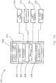
FIG. 7A is a block diagram illustrating electronic components of the passenger seating system that includes the passenger tray with the integrated user interface device, where the integrated user interface device includes a controller in communication with one or more controlled devices, in accordance with the instant invention; and -
FIG. 7B is a block diagram illustrating electronic components of the passenger seating system that includes the passenger tray with the integrated user interface device, where the integrated user interface device is communicatively coupled to a controller in communication with one or more controlled devices, in accordance with the instant invention. - Before explaining at least one embodiment of the instant invention in detail, it is to be understood that the instant invention is limited by the appended claims. The scope is not limited any further in its application to the details of construction and the arrangement of the components or steps or methodologies set forth in the following description or illustrated in the drawings. In the following detailed description of embodiments of the instant invention, numerous specific details are set forth in order to provide a more thorough understanding of the invention. However, it will be apparent to one of ordinary skill in the art having the benefit of the instant disclosure that the instant invention may be practiced without these specific details. In other instances, well-known features may not be described in detail to avoid unnecessarily complicating the instant disclosure. The instant invention is capable of other embodiments or of being practiced or carried out in various ways. Also, it is to be understood that the phraseology and terminology employed herein is for the purpose of description and should not be regarded as limiting.
- As used herein a letter following a reference numeral is intended to reference an embodiment of the feature or element that may be similar, but not necessarily identical, to a previously described element or feature bearing the same reference numeral (e.g., 1, 1a, 1b). Such shorthand notations are used for purposes of convenience only, and should not be construed to limit the inventive concepts disclosed herein in any way unless expressly stated to the contrary.
- Further, unless expressly stated to the contrary, "or" refers to an inclusive or and not to an exclusive or. For example, a condition A or B is satisfied by anyone of the following: A is true (or present) and B is false (or not present), A is false (or not present) and B is true (or present), and both A and B are true (or present).
- In addition, use of the "a" or "an" are employed to describe elements and components of embodiments of the instant invention. This is done merely for convenience and to give a general sense of the invention, and "a' and "an" are intended to include one or at least one and the singular also includes the plural unless it is obvious that it is meant otherwise.
- Finally, as used herein any reference to "one embodiment," or "some embodiments" means that a particular element, feature, structure, or characteristic described in connection with the embodiment is included in at least one embodiment of the instant invention. The appearances of the phrase "in some embodiments" in various places in the specification are not necessarily all referring to the same embodiment, and embodiments of the instant invention may include one or more of the features expressly described or inherently present herein, or any combination of sub-combination of two or more such features, along with any other features which may not necessarily be expressly described or inherently present in the instant disclosure.
- Broadly, embodiments of the instant invention are directed to a passenger tray with an integrated user interface device. When a passenger tray (e.g., meal, beverage, and/or activity tray) is deployed, the passenger tray may make it difficult for seated passengers to access controls for an in-flight entertainment (IFE) device (e.g., a media display device, audio device, and/or gaming device) or other controls (e.g., passenger chair controls, light system controls, flight attendant call button, etc.) that may be built into an armrest, center console, or the like. This inconveniences passengers, and in some cases, passengers may even spill a food or beverage while attempting to reach the controls. Accordingly, a passenger tray that does not limit passenger access to controls is disclosed.
- According to the instant invention, a passenger tray assembly includes a passenger tray with an integrated user interface device for controlling IFE devices and/or other passenger-accessible devices (e.g., passenger chair actuators, passenger light systems, flight attendant alert/communication systems, window shade and/or partition actuators, any combination thereof, and so forth). Various embodiments are described below with reference to
FIGS. 1 through 7B . -
FIG. 1 illustrates apassenger seating system 100 that includes apassenger tray assembly 200 with apassenger tray 204 having auser interface device 208 integrated within thepassenger tray 204. Thepassenger seating system 100 may includepassenger seating modules 102, rows, or the like, in a passenger cabin of an aircraft or any other vehicle. In an example embodiment, thepassenger tray assembly 200 is incorporated into a seating module 102 (e.g., a business-class or elite-class compartment) aboard a commercial aircraft or like seating area aboard a business jet or luxury aircraft. - The
seating module 102 includespassenger chair 104. In embodiments, thepassenger chair 104 includes an upper body support member 106 (e.g., a seat back) and aseat 108. In some embodiments, the upperbody support member 106 and theseat 108 may be separate structures disposed adjacent to one another. Alternatively, the upperbody support member 106 and theseat 108 can have one or more shared components. For example, the upperbody support member 106 and theseat 108 can have a shared cushion or covering, one or more shared mechanical linkages, and/or one or more shared actuators. The upperbody support member 106 may be configured to move relative to theseat 108. For example, the upperbody support member 106 can be configured to transition between upright and reclined positions. In some embodiments, theseat 108 is also repositionable. For example, theseat 108 may be configured to move forward/backward, upward/downward, and/or tilt. Theseat 108 and the upperbody support member 106 may be simultaneously actuated to transition from a sitting to a laying position. For example, theseat 108 may actuate forwards while the upperbody support member 106 reclines to place thepassenger chair 104 in a bed-like configuration. In some embodiments, thepassenger chair 104 can also include one ormore armrests 108 or armrest consoles adjacent to (e.g., on a left or right side) of theseat 108. - The
seating module 102 may further include at least onepartition 110 for partially demarcating thepassenger chair 104 from the cabin proper (e.g., defining a private area or a communal area). In embodiments, theseating module 102 can include a manually actuatedpartition 110 or anautomated partition 110. For example, in some embodiments, thepartition 110 may be manually actuated (e.g., raised, lowered, slid, unfolded, latched/unlatched, etc.) to open or close an entrance to theseating module 102. In other embodiments, thepartition 110 may be transitioned between open and closed positions by one or more actuators (e.g., motors, linear actuators, or the like). In some embodiments, theseating module 102 may include one or more control interfaces that generate signals to cause the actuators to open or close thepartition 110 based upon a user interaction (e.g., pressed button, toggled switch, etc.). - In embodiments, the
passenger seating system 100 includes anIFE device 112 for each passenger or group of passengers. For example, theIFE device 112 may include a media display device (e.g., a LCD, LED display, OLED display, or the like) for viewing streamed or recorded content (e.g., TV shows, movies, etc.), travel updates (e.g., flight tracking map, altitude, speed, outside air temperature, distance/time to destination, weather updates, and so forth). TheIFE device 112 may be integrated (e.g., at least partially embedded) within or coupled to another passenger chair, a wall structure, a console, or the like. TheIFE device 112 can also include an audio output device (e.g., speaker(s), audio output jack, and/or wireless transmitter (e.g., Bluetooth audio transmitter)). In some embodiments, theIFE device 112 includes a touchscreen display or other user input device (e.g., controller) that can be used to navigate theIFE device 112 menus, play, pause, stop, fast forward, and/or rewind, and/or interact with game media (e.g., video games, trivia games, etc.). - The
passenger tray assembly 200 can be implemented within theseating module 102. However, this is one example implementation, and in other embodiments, thepassenger tray assembly 200 may be implemented in a differently configuredpassenger seating system 100. - As shown in
FIGS. 1 through 4 , thepassenger tray assembly 200 includes abase member 202 and apassenger tray 204 that is coupled to thebase member 202 by at least onetray support member 206. In embodiments, thebase member 202 can be attached to or can make up a portion of an arm rest, a center console, a pedestal, a wall, another passenger chair, or any other fixture in the passenger cabin that is adjacent to thepassenger chair 104. Thetray support member 206 can be coupled to thepassenger tray 204 and configured to support thepassenger tray 204 in stowed and deployed configurations. For example, thetray support member 206 may be configured to suspend thepassenger tray 204 from thebase member 202 so that thepassenger tray 204 can be repositioned by pulling/pushing the passenger tray in a manner that causes thetray support member 206 to extend, swing, or rotate out from thebase member 202. - In some embodiments, the
passenger tray assembly 200 can include abase member 202,passenger tray 204, andtray support member 206 configured as described inU.S. Patent Application No. 16/114,450 passenger tray 204 may be supported by one or more (e.g., two)tray support members 206 that are coupled to a seatback of another passenger chair, or thepassenger tray 204 can be configured to fold out of a compartment in an arm rest or center console, or may deployable by another mechanism now or hereafter employed on aircrafts. - In some embodiments, the
passenger tray assembly 200 may also be at least partially automated. For example, thepassenger tray assembly 200 can include at least one actuator (e.g., a motor) configured to extend, rotate, swing, or otherwise deploy thetray support member 206. - The
passenger tray assembly 200 includes auser interface device 208 integrated (e.g., at least partially embedded) within thepassenger tray 204. For example, as shown inFIGS. 5 and 6 , acavity 220 is defined in a surface of thepassenger tray 204, and theuser interface device 208 is disposed within thecavity 220. In some embodiments, theuser interface device 208 is fully disposed within thecavity 220. For example, an outer surface of theuser interface device 208 may be flush with the surface of thepassenger tray 204 or set slightly below the surface of thepassenger tray 204. Theuser interface device 208 includes a capacitive touch interface 210 (e.g., a capacitive touchpad, capacitive touchscreen, and/or one or more capacitive touch sensors). Thecapacitive touch interface 210 can be configured to generate signals for controlling an IFE device (e.g., IFE device 112) and/or other passenger-accessible devices (e.g., passenger chair actuators, passenger light systems, flight attendant alert/communication systems, window shade and/or partition actuators, any combination thereof, and so forth). - As shown in
FIG. 3 , in embodiments, theuser interface device 208 includesicons 212 that indicate control actions (e.g., play, pause, stop, fast forward, rewind, next, back, on/off, etc.) associated with respective portions of thecapacitive touch interface 210. For example, in embodiments where thecapacitive touch interface 210 is a capacitive touchpad or one or more capacitive touch sensors, theuser interface device 208 may includeicons 212 formed over (e.g., printed or other applied to) an outer surface of the capacitive touchpad to indicate control actions associated with respective portions of the capacitive touchpad. In another example embodiment, thatcapacitive touch interface 210 is a capacitive touchscreen that can be configured to displayicons 212 that indicate control actions associated with respective portions of the capacitive touchscreen. - Referring again to
FIGS. 5 and 6 , theuser interface device 208 may be sealed from moisture, dust, or other debris by a cover layer 214 (e.g., a transparent cover layer) and/or gasket material 216 (e.g., rubber, foam, resin, and/or epoxy) disposed about theuser interface device 208 to seal the space between theuser interface device 208 and thecavity 220. In an example embodiment shown inFIG. 5 , theuser interface device 208 has acover layer 214 disposed upon thecapacitive touch interface 210 andgasket material 216 disposed between the edges of thecavity 220 and thecapacitive touch interface 210 and/orcover layer 214. In some embodiments, thecover layer 214 makes up a portion (e.g., an outermost layer) of thecapacitive touch interface 210. In another example embodiment shown inFIG. 6 (andFIG. 4 ), thepassenger tray 204 has acover layer 214 extending over theuser interface device 208 and at least a portion of the surface of thepassenger tray 204. In some embodiments, thecover layer 214 extends over thecavity 220 and the entire surface of the passenger tray 204 (e.g., as shown inFIGS. 4 and6 ) so that theuser interface device 208 is seamlessly integrated within the surface of thepassenger tray 204 and is protected from spills or any other form of moisture or debris that can potentially damage theuser interface device 208. - The
user interface device 208 can include a printed board 218 (e.g., a printed circuit board (PCB), printed wiring board (PWB), or the like) coupled to and/or forming a portion of thecapacitive touch interface 210. The printedboard 218 may include connectors (e.g., pins, sockets, ports, etc.) that can be coupled to one or more signal paths 222 (e.g., wires, cables, traces, etc.). In embodiments, one ormore signal paths 222 extend from thecavity 220 through a portion of thepassenger tray 204 and along or through thetray support member 206. The one ormore signal paths 222 can be configured to communicatively couple theuser interface device 208 with an IFE device (e.g., IFE device 112) and/or other passenger-accessible devices (e.g., passenger chair actuators, passenger light systems, flight attendant alert/communication systems, window shade and/or partition actuators, any combination thereof, and so forth). For example, in some embodiments, theuser interface device 208 may be directly coupled to an IFE device (e.g., IFE device 112) and/or other passenger-accessible devices (e.g., passenger chair actuators, passenger light systems, flight attendant alert/communication systems, window shade and/or partition actuators, any combination thereof, and so forth). In other embodiments, theuser interface device 208 may be coupled to a controller (or control system) that is configured to control an IFE device (e.g., IFE device 112) and/or other passenger-accessible devices (e.g., passenger chair actuators, passenger light systems, flight attendant alert/communication systems, window shade and/or partition actuators, any combination thereof, and so forth). -
FIGS. 7A and7B illustrate example embodiments of apassenger tray system 300 of electronic components associated with thepassenger tray assembly 200. In embodiments, thepassenger tray system 300 includes theuser interface device 208 having at least one capacitive touch interface 210 (e.g.,capacitive touchscreen 224 and/or capacitive touchpad/sensor 226). Theuser interface device 208 may include a controller 302 (e.g., as shown inFIG. 7A ) or can be communicatively coupled to the controller 302 (e.g., as shown inFIG. 7B ). For example, thecontroller 302 may be embedded in or connected to the printedboard 218, or thecontroller 302 can be communicatively coupled to thepassenger tray assembly 200 via the one ormore signal paths 222. These configurations are provided as examples; however, it is contemplated that variations on connectivity of thepassenger tray system 300 can be implemented (e.g., including, but not limited to, wireless connectivity or a mixture of wired and wireless connectivity) without departing from the scope of this disclosure. Furthermore, any number ofcontrollers 302 may be implemented. For example, theuser interface device 208 may include or can be coupled to arespective controller 302 that communicates with another controller (e.g., for an IFE device and/or another passenger-accessible device). - In embodiments, the
controller 302 includes aprocessor 304,memory 306, and acommunication interface 308. Theprocessor 304 provides processing functionality for at least thecontroller 302 and can include any number of processors, micro-controllers, circuitry, field programmable gate array (FPGA) or other processing systems, and resident or external memory for storing data, executable code, and other information accessed or generated by thecontroller 302. Theprocessor 304 can execute one or more software programs embodied in a non-transitory computer readable medium (e.g., memory 306) that implement techniques described herein. Theprocessor 304 is not limited by the materials from which it is formed or the processing mechanisms employed therein and, as such, can be implemented via semiconductor(s) and/or transistors (e.g., using electronic integrated circuit (IC) components), and so forth. - The
memory 306 can be an example of tangible, computer-readable storage medium that provides storage functionality to store various data and/or program code associated with operation of thecontroller 302/processor 304, such as software programs and/or code segments, or other data to instruct theprocessor 304, and possibly other components of thecontroller 302, to perform the functionality described herein. Thus, thememory 306 can store data, such as a program of instructions for operating thecontroller 302, including its components (e.g.,processor 304,communication interface 308, etc.), and so forth. It should be noted that while asingle memory 306 is described, a wide variety of types and combinations of memory (e.g., tangible, non-transitory memory) can be employed. Thememory 306 can be integral with theprocessor 304, can comprise stand-alone memory, or can be a combination of both. Some examples of thememory 306 can include removable and non-removable memory components, such as random-access memory (RAM), read-only memory (ROM), flash memory (e.g., a secure digital (SD) memory card, a mini-SD memory card, and/or a micro-SD memory card), solid-state drive (SSD) memory, magnetic memory, optical memory, universal serial bus (USB) memory devices, hard disk memory, external memory, and so forth. - The
communication interface 308 can be operatively configured to communicate with components of thecontroller 302. For example, thecommunication interface 308 can be configured to retrieve data from theprocessor 304 or other devices (e.g.,capacitive touch interface 210,IFE Device 310, actuator(s) 312,passenger light system 314, and/or flight attendant (FA) alert system 316), transmit data for storage in thememory 306, retrieve data from storage in thememory 306, and so forth. Thecommunication interface 308 can also be communicatively coupled with theprocessor 304 to facilitate data transfer between components of thecontroller 302 and theprocessor 304. It should be noted that while thecommunication interface 308 is described as a component of thecontroller 302, one or more components of thecommunication interface 308 can be implemented as external components communicatively coupled to thecontroller 302 via a wired and/or wireless connection. In embodiments, thecommunication interface 308 includes or is coupled to a transmitter, receiver, transceiver, physical connection interface, or any combination thereof. - In embodiments, the
capacitive touch interface 210 is configured to generate signals for controlling an IFE device 310 (e.g.,IFE device 112, or the like), one ormore actuators 312 for a passenger chair, window shade, partition, thepassenger tray assembly 200 itself, or any other automated/semi-automated passenger-accessible device, apassenger light system 314, aFA alert system 316, and/or any other passenger-accessible device. Thecontroller 302 can be configured to receive the signals from thecapacitive touch interface 210 and generate instructions and/or control signals based on thecapacitive touch interface 210 signals. Thecontroller 302 can be further configured to transmit the instructions and/or control signals to theIFE device 310, one ormore actuators 312,passenger light system 314,FA alert system 316, and/or other passenger-accessible device. In some embodiments, thecontroller 302 is configured to transmit the instructions and/or control signals directly to theIFE device 310, one ormore actuators 312,passenger light system 314,FA alert system 316, and/or other passenger-accessible device. In other embodiments, thecontroller 302 is configured to transmit the instructions and/or control signals to at least one other controller or control system that is configured to control theIFE device 310, one ormore actuators 312,passenger light system 314,FA alert system 316, and/or other passenger-accessible device. - In some embodiments, the
controller 302 can be further configured to receive information from theIFE device 310 or another passenger-accessible device. For example, thecontroller 302 may receive information regarding a display or audio content output by the IFE device 310 (e.g., movie, TV show, flight information, game, safety alert, etc.). In some embodiments, thecontroller 302 may be configured to at least partially disable thecapacitive touch interface 210 when safety alerts or other alerts that are directed at all passengers are broadcast or provided via theIFE device 310. In embodiments where thecapacitive touch interface 210 is acapacitive touchscreen 224, thecontroller 302 may be configured to modify thedisplay icons 212 based on the content being output by theIFE device 310. In some embodiments, thecontroller 302 can also be configured to provide visual feedback through the capacitive touchscreen 224 (e.g., to indicate volume, track bar display, lights on/off, actuator positions, etc.) based upon user inputs to theuser interface device 208 and/or information received from the one or more passenger-accessible devices being controlled. - It is to be understood that embodiments of the methods according to the instant invention may include one or more of the steps described herein. Further, such steps may be carried out in any desired order and two or more of the steps may be carried out simultaneously with one another. Two or more of the steps disclosed herein may be combined in a single step, and in some embodiments, one or more of the steps may be carried out as two or more sub-steps. Further, other steps or sub-steps may be carried in addition to, or as substitutes to one or more of the steps disclosed herein.
- From the above description, it is clear that the instant invention is well adapted to carry out the objects and to attain the advantages mentioned herein as well as those inherent in the instant invention. While presently preferred embodiments of the instant invention have been described for purposes of this disclosure, it will be understood that numerous changes may be made which are in the scope of the invention as defined in the appended claims and will readily suggest themselves to those skilled in the art.
Claims (9)
- A passenger tray assembly (200), comprising:a passenger tray with (204) a cavity (220) defined in a surface of the passenger tray (204);a tray support member (206) coupled to the passenger tray (204) and configured to support the passenger tray (204) in stowed and deployed configurations;a user interface device (208, 210,224, 226) disposed within the cavity (220), the user interface device (208, 210, 224, 226) configured to generate signals for controlling an in-flight entertainment device (112, 310), an actuator (312) of a passenger chair, a passenger light system (314), a flight attendant alert system (316) and/or window shade and/or partition actuators; andone or more signal paths (222) for communicatively coupling the user interface device (208, 210, 224, 226) with the in-flight entertainment device (112, 310), the one or more signal paths (222) extending from the cavity (220) through a portion of the passenger tray (204) and along or through the tray support member (206).
- The passenger tray assembly according to claim 1, wherein the user interface includes a capacitive touch interface (210), preferably a captive touchpad.
- The passenger tray assembly according to claim 2, wherein the user interface device includes control icons (212) formed over the capacitive touchpad to indicate control actions associated with respective portions of the capacitive touchpad.
- The passenger tray assembly according to one or more of the preceding claims, wherein the capacitive touch interface comprises a capacitive touchscreen (224).
- The passenger tray assembly according to claim 4, wherein the capacitive touchscreen (224) is configured to display control icons (212) to indicate control actions associated with respective portions of the capacitive touchscreen (224).
- The passenger tray assembly according to one or more of the preceding claims, further comprising a gasket material (216) disposed about the user interface device (208, 210, 224, 226) for sealing a space between the user interface device (208, 210, 22, 226) and the cavity (220).
- The passenger tray assembly according to one or more of the preceding claims, further comprising a cover layer (214) extending over the user interface device (208, 210, 224, 226) and at least a portion of the surface of the passenger tray (204).
- The passenger tray assembly according to one or more of the preceding claims, wherein the capacitive touch interface (208, 210, 224, 226) is further configured to generate signals for controlling at least one of: an actuator (312) of a passenger chair, a passenger light system (314), or a flight attendant alert system (316).
- A passenger seating system (100) including a passenger tray assembly (200) according to one or more of the preceding claims.
Applications Claiming Priority (1)
| Application Number | Priority Date | Filing Date | Title |
|---|---|---|---|
| US16/114,620 US10926878B2 (en) | 2018-08-28 | 2018-08-28 | Passenger tray with integrated user interface device |
Publications (2)
| Publication Number | Publication Date |
|---|---|
| EP3617070A1 true EP3617070A1 (en) | 2020-03-04 |
| EP3617070B1 EP3617070B1 (en) | 2023-10-11 |
Family
ID=67777150
Family Applications (1)
| Application Number | Title | Priority Date | Filing Date |
|---|---|---|---|
| EP19194017.0A Active EP3617070B1 (en) | 2018-08-28 | 2019-08-28 | Passenger tray with integrated user interface device |
Country Status (2)
| Country | Link |
|---|---|
| US (1) | US10926878B2 (en) |
| EP (1) | EP3617070B1 (en) |
Cited By (1)
| Publication number | Priority date | Publication date | Assignee | Title |
|---|---|---|---|---|
| DE102019118707A1 (en) * | 2019-07-10 | 2021-01-14 | Recaro Aircraft Seating Gmbh & Co. Kg | Aircraft seat assembly |
Families Citing this family (4)
| Publication number | Priority date | Publication date | Assignee | Title |
|---|---|---|---|---|
| DE102019006897A1 (en) * | 2019-10-02 | 2021-04-08 | Daimler Ag | Table device and vehicle |
| US12126955B1 (en) * | 2021-10-14 | 2024-10-22 | Rockwell Collins, Inc. | Dynamic cabin digital headphone jack |
| DE102023106652A1 (en) * | 2023-03-16 | 2024-09-19 | Audi Aktiengesellschaft | Centre armrest for a motor vehicle, motor vehicle and method for operating a centre armrest |
| US12312086B2 (en) * | 2023-04-14 | 2025-05-27 | B/E Aerospace, Inc. | Controller feedback system |
Citations (5)
| Publication number | Priority date | Publication date | Assignee | Title |
|---|---|---|---|---|
| GB2340389A (en) * | 1998-07-11 | 2000-02-23 | Mile High Marketing Limited | Vehicle table with inbuilt flat screen display |
| US20060075934A1 (en) * | 2004-09-28 | 2006-04-13 | Pranil Ram | Passenger keyboard and display apparatus, and a system and method for delivering content to users of such apparatus |
| WO2014075040A1 (en) * | 2012-11-12 | 2014-05-15 | Zodiac Seats Us Llc | Integrated keyboard tray |
| US9205914B1 (en) * | 2013-01-31 | 2015-12-08 | Bombardier Inc. | Distributed architecture for a system and a method of operation of the system incorporating a graphical user interface controlling functions in a vehicle cabin |
| US20160170499A1 (en) * | 2014-12-15 | 2016-06-16 | Panasonic Avionics Corporation | Data input device for informatiion processing apparatus |
Family Cites Families (7)
| Publication number | Priority date | Publication date | Assignee | Title |
|---|---|---|---|---|
| US20030184957A1 (en) * | 2002-04-02 | 2003-10-02 | Stahl Robert Edward | Computer keyboard integrated in aircraft seatback tray table |
| US20080061609A1 (en) * | 2006-09-06 | 2008-03-13 | Williamson Robert V | Airplane passenger seats with embedded displays and other i/o components for interfacing with passenger laptop computers |
| EP2483104B1 (en) * | 2009-10-02 | 2017-12-20 | Panasonic Avionics Corporation | System and method for interacting with information systems |
| US10212393B2 (en) * | 2010-03-04 | 2019-02-19 | Livetv, Llc | Aircraft in-flight entertainment system with enhanced passenger control units and associated methods |
| US8934063B2 (en) * | 2011-03-18 | 2015-01-13 | Skycast Solutions Inc. | In-flight entertainment system |
| US9128594B1 (en) * | 2011-09-02 | 2015-09-08 | Rockwell Collins, Inc. | Touch interfaces and controls for aviation displays |
| US8826830B2 (en) * | 2011-10-13 | 2014-09-09 | Nick Pajic | Tray table with rotatable inner tray for electronic device docking |
-
2018
- 2018-08-28 US US16/114,620 patent/US10926878B2/en active Active
-
2019
- 2019-08-28 EP EP19194017.0A patent/EP3617070B1/en active Active
Patent Citations (5)
| Publication number | Priority date | Publication date | Assignee | Title |
|---|---|---|---|---|
| GB2340389A (en) * | 1998-07-11 | 2000-02-23 | Mile High Marketing Limited | Vehicle table with inbuilt flat screen display |
| US20060075934A1 (en) * | 2004-09-28 | 2006-04-13 | Pranil Ram | Passenger keyboard and display apparatus, and a system and method for delivering content to users of such apparatus |
| WO2014075040A1 (en) * | 2012-11-12 | 2014-05-15 | Zodiac Seats Us Llc | Integrated keyboard tray |
| US9205914B1 (en) * | 2013-01-31 | 2015-12-08 | Bombardier Inc. | Distributed architecture for a system and a method of operation of the system incorporating a graphical user interface controlling functions in a vehicle cabin |
| US20160170499A1 (en) * | 2014-12-15 | 2016-06-16 | Panasonic Avionics Corporation | Data input device for informatiion processing apparatus |
Cited By (2)
| Publication number | Priority date | Publication date | Assignee | Title |
|---|---|---|---|---|
| DE102019118707A1 (en) * | 2019-07-10 | 2021-01-14 | Recaro Aircraft Seating Gmbh & Co. Kg | Aircraft seat assembly |
| DE102019118707B4 (en) * | 2019-07-10 | 2025-08-07 | Recaro Aircraft Seating Gmbh & Co. Kg | Aircraft seat device |
Also Published As
| Publication number | Publication date |
|---|---|
| US10926878B2 (en) | 2021-02-23 |
| EP3617070B1 (en) | 2023-10-11 |
| US20200070982A1 (en) | 2020-03-05 |
Similar Documents
| Publication | Publication Date | Title |
|---|---|---|
| EP3617070B1 (en) | Passenger tray with integrated user interface device | |
| US11618568B2 (en) | Integrated aircraft seat control panel | |
| CN102770346B (en) | System and method for providing an integrated user interface system at a seat | |
| US10372231B2 (en) | Aircraft having gesture-based control for an onboard passenger service unit | |
| CA2807848C (en) | Integrated user interface system and method | |
| US10926880B1 (en) | Timed passenger tray with infinite position | |
| US20090109036A1 (en) | System and Method for Alternative Communication | |
| EP2828160B1 (en) | Premium class aircraft passenger suite with separate seating areas | |
| EP3936378B1 (en) | Dynamic electro-mechanical ottoman | |
| US11498681B2 (en) | Integrated seating armrest, stowage and bed surface | |
| US11613359B2 (en) | Bench-back aircraft seat for aircraft passenger compartment suites | |
| CN101595032A (en) | Seat device in vehicle cockpit | |
| EP3598643A1 (en) | Customizable gesture controller | |
| US20240308662A1 (en) | Passenger seating apparatus with movable display | |
| GB2340389A (en) | Vehicle table with inbuilt flat screen display | |
| US10370109B2 (en) | Non-intrusive and reclining seating arrangement for an airplane or other means of transportation | |
| EP3862271B1 (en) | Combined divan aircraft seat for aircraft passenger compartment suites | |
| EP3626615B1 (en) | Passenger chair component monitoring system | |
| EP4446222A1 (en) | Controller feedback system and method | |
| US12134472B2 (en) | System including stowable tablet holder apparatus | |
| US11338740B1 (en) | Monitor mounting apparatus | |
| CN116923231A (en) | Self-driving vehicles with self-service dining pods |
Legal Events
| Date | Code | Title | Description |
|---|---|---|---|
| PUAI | Public reference made under article 153(3) epc to a published international application that has entered the european phase |
Free format text: ORIGINAL CODE: 0009012 |
|
| STAA | Information on the status of an ep patent application or granted ep patent |
Free format text: STATUS: THE APPLICATION HAS BEEN PUBLISHED |
|
| AK | Designated contracting states |
Kind code of ref document: A1 Designated state(s): AL AT BE BG CH CY CZ DE DK EE ES FI FR GB GR HR HU IE IS IT LI LT LU LV MC MK MT NL NO PL PT RO RS SE SI SK SM TR |
|
| AX | Request for extension of the european patent |
Extension state: BA ME |
|
| STAA | Information on the status of an ep patent application or granted ep patent |
Free format text: STATUS: REQUEST FOR EXAMINATION WAS MADE |
|
| 17P | Request for examination filed |
Effective date: 20200630 |
|
| RBV | Designated contracting states (corrected) |
Designated state(s): AL AT BE BG CH CY CZ DE DK EE ES FI FR GB GR HR HU IE IS IT LI LT LU LV MC MK MT NL NO PL PT RO RS SE SI SK SM TR |
|
| STAA | Information on the status of an ep patent application or granted ep patent |
Free format text: STATUS: EXAMINATION IS IN PROGRESS |
|
| 17Q | First examination report despatched |
Effective date: 20201117 |
|
| GRAP | Despatch of communication of intention to grant a patent |
Free format text: ORIGINAL CODE: EPIDOSNIGR1 |
|
| STAA | Information on the status of an ep patent application or granted ep patent |
Free format text: STATUS: GRANT OF PATENT IS INTENDED |
|
| INTG | Intention to grant announced |
Effective date: 20230512 |
|
| P01 | Opt-out of the competence of the unified patent court (upc) registered |
Effective date: 20230606 |
|
| GRAS | Grant fee paid |
Free format text: ORIGINAL CODE: EPIDOSNIGR3 |
|
| GRAA | (expected) grant |
Free format text: ORIGINAL CODE: 0009210 |
|
| STAA | Information on the status of an ep patent application or granted ep patent |
Free format text: STATUS: THE PATENT HAS BEEN GRANTED |
|
| AK | Designated contracting states |
Kind code of ref document: B1 Designated state(s): AL AT BE BG CH CY CZ DE DK EE ES FI FR GB GR HR HU IE IS IT LI LT LU LV MC MK MT NL NO PL PT RO RS SE SI SK SM TR |
|
| REG | Reference to a national code |
Ref country code: GB Ref legal event code: FG4D |
|
| REG | Reference to a national code |
Ref country code: CH Ref legal event code: EP |
|
| REG | Reference to a national code |
Ref country code: DE Ref legal event code: R096 Ref document number: 602019039029 Country of ref document: DE |
|
| REG | Reference to a national code |
Ref country code: IE Ref legal event code: FG4D |
|
| REG | Reference to a national code |
Ref country code: LT Ref legal event code: MG9D |
|
| REG | Reference to a national code |
Ref country code: NL Ref legal event code: MP Effective date: 20231011 |
|
| REG | Reference to a national code |
Ref country code: AT Ref legal event code: MK05 Ref document number: 1620003 Country of ref document: AT Kind code of ref document: T Effective date: 20231011 |
|
| PG25 | Lapsed in a contracting state [announced via postgrant information from national office to epo] |
Ref country code: NL Free format text: LAPSE BECAUSE OF FAILURE TO SUBMIT A TRANSLATION OF THE DESCRIPTION OR TO PAY THE FEE WITHIN THE PRESCRIBED TIME-LIMIT Effective date: 20231011 |
|
| PG25 | Lapsed in a contracting state [announced via postgrant information from national office to epo] |
Ref country code: GR Free format text: LAPSE BECAUSE OF FAILURE TO SUBMIT A TRANSLATION OF THE DESCRIPTION OR TO PAY THE FEE WITHIN THE PRESCRIBED TIME-LIMIT Effective date: 20240112 |
|
| PG25 | Lapsed in a contracting state [announced via postgrant information from national office to epo] |
Ref country code: IS Free format text: LAPSE BECAUSE OF FAILURE TO SUBMIT A TRANSLATION OF THE DESCRIPTION OR TO PAY THE FEE WITHIN THE PRESCRIBED TIME-LIMIT Effective date: 20240211 |
|
| PG25 | Lapsed in a contracting state [announced via postgrant information from national office to epo] |
Ref country code: LT Free format text: LAPSE BECAUSE OF FAILURE TO SUBMIT A TRANSLATION OF THE DESCRIPTION OR TO PAY THE FEE WITHIN THE PRESCRIBED TIME-LIMIT Effective date: 20231011 |
|
| PG25 | Lapsed in a contracting state [announced via postgrant information from national office to epo] |
Ref country code: AT Free format text: LAPSE BECAUSE OF FAILURE TO SUBMIT A TRANSLATION OF THE DESCRIPTION OR TO PAY THE FEE WITHIN THE PRESCRIBED TIME-LIMIT Effective date: 20231011 |
|
| PG25 | Lapsed in a contracting state [announced via postgrant information from national office to epo] |
Ref country code: ES Free format text: LAPSE BECAUSE OF FAILURE TO SUBMIT A TRANSLATION OF THE DESCRIPTION OR TO PAY THE FEE WITHIN THE PRESCRIBED TIME-LIMIT Effective date: 20231011 |
|
| PG25 | Lapsed in a contracting state [announced via postgrant information from national office to epo] |
Ref country code: LT Free format text: LAPSE BECAUSE OF FAILURE TO SUBMIT A TRANSLATION OF THE DESCRIPTION OR TO PAY THE FEE WITHIN THE PRESCRIBED TIME-LIMIT Effective date: 20231011 Ref country code: IS Free format text: LAPSE BECAUSE OF FAILURE TO SUBMIT A TRANSLATION OF THE DESCRIPTION OR TO PAY THE FEE WITHIN THE PRESCRIBED TIME-LIMIT Effective date: 20240211 Ref country code: GR Free format text: LAPSE BECAUSE OF FAILURE TO SUBMIT A TRANSLATION OF THE DESCRIPTION OR TO PAY THE FEE WITHIN THE PRESCRIBED TIME-LIMIT Effective date: 20240112 Ref country code: ES Free format text: LAPSE BECAUSE OF FAILURE TO SUBMIT A TRANSLATION OF THE DESCRIPTION OR TO PAY THE FEE WITHIN THE PRESCRIBED TIME-LIMIT Effective date: 20231011 Ref country code: BG Free format text: LAPSE BECAUSE OF FAILURE TO SUBMIT A TRANSLATION OF THE DESCRIPTION OR TO PAY THE FEE WITHIN THE PRESCRIBED TIME-LIMIT Effective date: 20240111 Ref country code: AT Free format text: LAPSE BECAUSE OF FAILURE TO SUBMIT A TRANSLATION OF THE DESCRIPTION OR TO PAY THE FEE WITHIN THE PRESCRIBED TIME-LIMIT Effective date: 20231011 Ref country code: PT Free format text: LAPSE BECAUSE OF FAILURE TO SUBMIT A TRANSLATION OF THE DESCRIPTION OR TO PAY THE FEE WITHIN THE PRESCRIBED TIME-LIMIT Effective date: 20240212 |
|
| PG25 | Lapsed in a contracting state [announced via postgrant information from national office to epo] |
Ref country code: SE Free format text: LAPSE BECAUSE OF FAILURE TO SUBMIT A TRANSLATION OF THE DESCRIPTION OR TO PAY THE FEE WITHIN THE PRESCRIBED TIME-LIMIT Effective date: 20231011 Ref country code: RS Free format text: LAPSE BECAUSE OF FAILURE TO SUBMIT A TRANSLATION OF THE DESCRIPTION OR TO PAY THE FEE WITHIN THE PRESCRIBED TIME-LIMIT Effective date: 20231011 Ref country code: PL Free format text: LAPSE BECAUSE OF FAILURE TO SUBMIT A TRANSLATION OF THE DESCRIPTION OR TO PAY THE FEE WITHIN THE PRESCRIBED TIME-LIMIT Effective date: 20231011 Ref country code: NO Free format text: LAPSE BECAUSE OF FAILURE TO SUBMIT A TRANSLATION OF THE DESCRIPTION OR TO PAY THE FEE WITHIN THE PRESCRIBED TIME-LIMIT Effective date: 20240111 Ref country code: LV Free format text: LAPSE BECAUSE OF FAILURE TO SUBMIT A TRANSLATION OF THE DESCRIPTION OR TO PAY THE FEE WITHIN THE PRESCRIBED TIME-LIMIT Effective date: 20231011 Ref country code: HR Free format text: LAPSE BECAUSE OF FAILURE TO SUBMIT A TRANSLATION OF THE DESCRIPTION OR TO PAY THE FEE WITHIN THE PRESCRIBED TIME-LIMIT Effective date: 20231011 |
|
| PG25 | Lapsed in a contracting state [announced via postgrant information from national office to epo] |
Ref country code: DK Free format text: LAPSE BECAUSE OF FAILURE TO SUBMIT A TRANSLATION OF THE DESCRIPTION OR TO PAY THE FEE WITHIN THE PRESCRIBED TIME-LIMIT Effective date: 20231011 |
|
| REG | Reference to a national code |
Ref country code: DE Ref legal event code: R097 Ref document number: 602019039029 Country of ref document: DE |
|
| PG25 | Lapsed in a contracting state [announced via postgrant information from national office to epo] |
Ref country code: CZ Free format text: LAPSE BECAUSE OF FAILURE TO SUBMIT A TRANSLATION OF THE DESCRIPTION OR TO PAY THE FEE WITHIN THE PRESCRIBED TIME-LIMIT Effective date: 20231011 |
|
| PG25 | Lapsed in a contracting state [announced via postgrant information from national office to epo] |
Ref country code: SK Free format text: LAPSE BECAUSE OF FAILURE TO SUBMIT A TRANSLATION OF THE DESCRIPTION OR TO PAY THE FEE WITHIN THE PRESCRIBED TIME-LIMIT Effective date: 20231011 |
|
| PG25 | Lapsed in a contracting state [announced via postgrant information from national office to epo] |
Ref country code: SM Free format text: LAPSE BECAUSE OF FAILURE TO SUBMIT A TRANSLATION OF THE DESCRIPTION OR TO PAY THE FEE WITHIN THE PRESCRIBED TIME-LIMIT Effective date: 20231011 Ref country code: SK Free format text: LAPSE BECAUSE OF FAILURE TO SUBMIT A TRANSLATION OF THE DESCRIPTION OR TO PAY THE FEE WITHIN THE PRESCRIBED TIME-LIMIT Effective date: 20231011 Ref country code: RO Free format text: LAPSE BECAUSE OF FAILURE TO SUBMIT A TRANSLATION OF THE DESCRIPTION OR TO PAY THE FEE WITHIN THE PRESCRIBED TIME-LIMIT Effective date: 20231011 Ref country code: IT Free format text: LAPSE BECAUSE OF FAILURE TO SUBMIT A TRANSLATION OF THE DESCRIPTION OR TO PAY THE FEE WITHIN THE PRESCRIBED TIME-LIMIT Effective date: 20231011 Ref country code: EE Free format text: LAPSE BECAUSE OF FAILURE TO SUBMIT A TRANSLATION OF THE DESCRIPTION OR TO PAY THE FEE WITHIN THE PRESCRIBED TIME-LIMIT Effective date: 20231011 Ref country code: DK Free format text: LAPSE BECAUSE OF FAILURE TO SUBMIT A TRANSLATION OF THE DESCRIPTION OR TO PAY THE FEE WITHIN THE PRESCRIBED TIME-LIMIT Effective date: 20231011 Ref country code: CZ Free format text: LAPSE BECAUSE OF FAILURE TO SUBMIT A TRANSLATION OF THE DESCRIPTION OR TO PAY THE FEE WITHIN THE PRESCRIBED TIME-LIMIT Effective date: 20231011 |
|
| PLBE | No opposition filed within time limit |
Free format text: ORIGINAL CODE: 0009261 |
|
| STAA | Information on the status of an ep patent application or granted ep patent |
Free format text: STATUS: NO OPPOSITION FILED WITHIN TIME LIMIT |
|
| 26N | No opposition filed |
Effective date: 20240712 |
|
| PG25 | Lapsed in a contracting state [announced via postgrant information from national office to epo] |
Ref country code: SI Free format text: LAPSE BECAUSE OF FAILURE TO SUBMIT A TRANSLATION OF THE DESCRIPTION OR TO PAY THE FEE WITHIN THE PRESCRIBED TIME-LIMIT Effective date: 20231011 |
|
| PG25 | Lapsed in a contracting state [announced via postgrant information from national office to epo] |
Ref country code: SI Free format text: LAPSE BECAUSE OF FAILURE TO SUBMIT A TRANSLATION OF THE DESCRIPTION OR TO PAY THE FEE WITHIN THE PRESCRIBED TIME-LIMIT Effective date: 20231011 |
|
| REG | Reference to a national code |
Ref country code: CH Ref legal event code: PL |
|
| PG25 | Lapsed in a contracting state [announced via postgrant information from national office to epo] |
Ref country code: LU Free format text: LAPSE BECAUSE OF NON-PAYMENT OF DUE FEES Effective date: 20240828 |
|
| PG25 | Lapsed in a contracting state [announced via postgrant information from national office to epo] |
Ref country code: MC Free format text: LAPSE BECAUSE OF FAILURE TO SUBMIT A TRANSLATION OF THE DESCRIPTION OR TO PAY THE FEE WITHIN THE PRESCRIBED TIME-LIMIT Effective date: 20231011 Ref country code: CH Free format text: LAPSE BECAUSE OF NON-PAYMENT OF DUE FEES Effective date: 20240831 |
|
| REG | Reference to a national code |
Ref country code: BE Ref legal event code: MM Effective date: 20240831 |
|
| PG25 | Lapsed in a contracting state [announced via postgrant information from national office to epo] |
Ref country code: BE Free format text: LAPSE BECAUSE OF NON-PAYMENT OF DUE FEES Effective date: 20240831 |
|
| PG25 | Lapsed in a contracting state [announced via postgrant information from national office to epo] |
Ref country code: IE Free format text: LAPSE BECAUSE OF NON-PAYMENT OF DUE FEES Effective date: 20240828 |
|
| PG25 | Lapsed in a contracting state [announced via postgrant information from national office to epo] |
Ref country code: FI Free format text: LAPSE BECAUSE OF FAILURE TO SUBMIT A TRANSLATION OF THE DESCRIPTION OR TO PAY THE FEE WITHIN THE PRESCRIBED TIME-LIMIT Effective date: 20231011 |
|
| PGFP | Annual fee paid to national office [announced via postgrant information from national office to epo] |
Ref country code: DE Payment date: 20250724 Year of fee payment: 7 |
|
| PGFP | Annual fee paid to national office [announced via postgrant information from national office to epo] |
Ref country code: GB Payment date: 20250725 Year of fee payment: 7 |
|
| PGFP | Annual fee paid to national office [announced via postgrant information from national office to epo] |
Ref country code: FR Payment date: 20250723 Year of fee payment: 7 |
|
| PG25 | Lapsed in a contracting state [announced via postgrant information from national office to epo] |
Ref country code: CY Free format text: LAPSE BECAUSE OF FAILURE TO SUBMIT A TRANSLATION OF THE DESCRIPTION OR TO PAY THE FEE WITHIN THE PRESCRIBED TIME-LIMIT; INVALID AB INITIO Effective date: 20190828 |
|
| PG25 | Lapsed in a contracting state [announced via postgrant information from national office to epo] |
Ref country code: HU Free format text: LAPSE BECAUSE OF FAILURE TO SUBMIT A TRANSLATION OF THE DESCRIPTION OR TO PAY THE FEE WITHIN THE PRESCRIBED TIME-LIMIT; INVALID AB INITIO Effective date: 20190828 |