EP3617064A1 - Ballistic resistant drive shaft - Google Patents
Ballistic resistant drive shaft Download PDFInfo
- Publication number
- EP3617064A1 EP3617064A1 EP19193461.1A EP19193461A EP3617064A1 EP 3617064 A1 EP3617064 A1 EP 3617064A1 EP 19193461 A EP19193461 A EP 19193461A EP 3617064 A1 EP3617064 A1 EP 3617064A1
- Authority
- EP
- European Patent Office
- Prior art keywords
- core
- drive shaft
- layer
- energy absorption
- recited
- Prior art date
- Legal status (The legal status is an assumption and is not a legal conclusion. Google has not performed a legal analysis and makes no representation as to the accuracy of the status listed.)
- Granted
Links
Images




Classifications
-
- B—PERFORMING OPERATIONS; TRANSPORTING
- B64—AIRCRAFT; AVIATION; COSMONAUTICS
- B64C—AEROPLANES; HELICOPTERS
- B64C27/00—Rotorcraft; Rotors peculiar thereto
- B64C27/04—Helicopters
- B64C27/12—Rotor drives
- B64C27/14—Direct drive between power plant and rotor hub
-
- B—PERFORMING OPERATIONS; TRANSPORTING
- B29—WORKING OF PLASTICS; WORKING OF SUBSTANCES IN A PLASTIC STATE IN GENERAL
- B29C—SHAPING OR JOINING OF PLASTICS; SHAPING OF MATERIAL IN A PLASTIC STATE, NOT OTHERWISE PROVIDED FOR; AFTER-TREATMENT OF THE SHAPED PRODUCTS, e.g. REPAIRING
- B29C70/00—Shaping composites, i.e. plastics material comprising reinforcements, fillers or preformed parts, e.g. inserts
- B29C70/04—Shaping composites, i.e. plastics material comprising reinforcements, fillers or preformed parts, e.g. inserts comprising reinforcements only, e.g. self-reinforcing plastics
- B29C70/28—Shaping operations therefor
- B29C70/30—Shaping by lay-up, i.e. applying fibres, tape or broadsheet on a mould, former or core; Shaping by spray-up, i.e. spraying of fibres on a mould, former or core
-
- B—PERFORMING OPERATIONS; TRANSPORTING
- B64—AIRCRAFT; AVIATION; COSMONAUTICS
- B64D—EQUIPMENT FOR FITTING IN OR TO AIRCRAFT; FLIGHT SUITS; PARACHUTES; ARRANGEMENT OR MOUNTING OF POWER PLANTS OR PROPULSION TRANSMISSIONS IN AIRCRAFT
- B64D35/00—Transmitting power from power plants to propellers or rotors; Arrangements of transmissions
-
- F—MECHANICAL ENGINEERING; LIGHTING; HEATING; WEAPONS; BLASTING
- F16—ENGINEERING ELEMENTS AND UNITS; GENERAL MEASURES FOR PRODUCING AND MAINTAINING EFFECTIVE FUNCTIONING OF MACHINES OR INSTALLATIONS; THERMAL INSULATION IN GENERAL
- F16C—SHAFTS; FLEXIBLE SHAFTS; ELEMENTS OR CRANKSHAFT MECHANISMS; ROTARY BODIES OTHER THAN GEARING ELEMENTS; BEARINGS
- F16C3/00—Shafts; Axles; Cranks; Eccentrics
- F16C3/02—Shafts; Axles
- F16C3/026—Shafts made of fibre reinforced resin
-
- F—MECHANICAL ENGINEERING; LIGHTING; HEATING; WEAPONS; BLASTING
- F16—ENGINEERING ELEMENTS AND UNITS; GENERAL MEASURES FOR PRODUCING AND MAINTAINING EFFECTIVE FUNCTIONING OF MACHINES OR INSTALLATIONS; THERMAL INSULATION IN GENERAL
- F16C—SHAFTS; FLEXIBLE SHAFTS; ELEMENTS OR CRANKSHAFT MECHANISMS; ROTARY BODIES OTHER THAN GEARING ELEMENTS; BEARINGS
- F16C2326/00—Articles relating to transporting
- F16C2326/01—Parts of vehicles in general
- F16C2326/06—Drive shafts
-
- F—MECHANICAL ENGINEERING; LIGHTING; HEATING; WEAPONS; BLASTING
- F16—ENGINEERING ELEMENTS AND UNITS; GENERAL MEASURES FOR PRODUCING AND MAINTAINING EFFECTIVE FUNCTIONING OF MACHINES OR INSTALLATIONS; THERMAL INSULATION IN GENERAL
- F16C—SHAFTS; FLEXIBLE SHAFTS; ELEMENTS OR CRANKSHAFT MECHANISMS; ROTARY BODIES OTHER THAN GEARING ELEMENTS; BEARINGS
- F16C2326/00—Articles relating to transporting
- F16C2326/43—Aeroplanes; Helicopters
Definitions
- This disclosure relates to power transmission systems, and particularly to drive shafts for driving one or more components.
- Aircraft typically include one or more drive shafts that interconnect a powerplant system with one or more aircraft components.
- Example aircraft components can include tail and main rotor blades to provide propulsion.
- Other aircraft components can include one or more pivotable flaps to manoeuvre the aircraft.
- the aircraft may experience ballistic threats such as surface-to-air and air-to-air munitions including projectiles, or in general impact by foreign objects, for example tools, runway debris, etc., which may strike the drive shafts.
- damages during operation can be expected due to service (e.g., debris), installation, transportation and other impacts.
- a drive shaft for an aircraft includes an elongated core extending between a pair of opposed couplings, an energy absorption layer made of a composite comprising metal, the energy absorption layer disposed on the core, and a first composite ballistic layer disposed on the core.
- a power transmission system for an aircraft includes a gearbox and a drive shaft.
- the drive shaft includes a first coupling coupled to an engine, a second coupling coupled to the gearbox, and a tubular core interconnecting the first and second couplings.
- An energy absorption layer is made of a composite comprising metal. The energy absorption layer is disposed on the core.
- a first composite ballistic layer is disposed on the energy absorption layer.
- a method of fabricating a drive shaft for an aircraft includes forming an energy absorption layer on an elongated core, the elongated core extending between first and second couplings, and the energy absorption layer comprising metal.
- the method includes the step of forming a first composite ballistic layer on the energy absorption layer.
- Figure 1 illustrates an exemplary aircraft 10.
- the aircraft 10 is a rotary-wing aircraft.
- Figure 2 illustrates an exemplary power transmission system 11 which can be incorporated into the aircraft 10 of Figure 1 .
- the aircraft 10 includes a main rotor assembly 12 supported by an airframe 14.
- the airframe 14 includes an extending tail 16 which mounts a tail rotor assembly 18.
- the main rotor assembly 12 includes a main rotor 20 driven about a first axis of rotation A through a main rotor gearbox 22 by a powerplant system 24.
- the powerplant system 24 generates power available for flight operations.
- the power plant system 24 includes one or more engine packages to drive a main rotor hub 25 of the main rotor 20 and a tail rotor 26 of the tail rotor assembly 18.
- the powerplant system 24 includes at least one engine package ENGl.
- the powerplant system 24 includes two or more engine packages.
- Each engine package ENGl can include a gas turbine engine. Gas turbine engines are known and include a combustor and one or more rotatable spools. Each spool can include a turbine driving a compressor and/or an output of the engine.
- the main rotor 20 includes a plurality of rotor blades 28 mounted or otherwise secured to the main rotor hub 25.
- the rotor blades 28 are rotatable about the first axis of rotation A to provide propulsion for the aircraft 10.
- the tail rotor 26 includes a plurality of rotor blades 30 mounted or otherwise secured to a tail rotor hub 32.
- the rotor blades 30 are rotatable about a second axis of rotation B to counteract torque generated by rotation of the rotor blades 28.
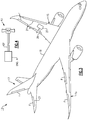
- Figure 3 illustrates an aircraft 13 according to an example.
- the aircraft 13 includes a pair of wings 15 and a tail section 17 that extend from a fuselage 19.
- the aircraft 13 includes one or more mechanical loads 21.
- the mechanical loads 21 can include one or more moveable surfaces such as pivotable flaps F.
- the pivotable flaps F can be located along a portion of one or more of the wings 15 and/or the tail section 17 to augment control of the aircraft 13.
- Example flaps include ailerons, elevators, rudders, spoilers, leading edge flaps and slats, and components of landing gear assemblies.
- Each mechanical load 21 can be moved by an actuator 27 interconnected with the mechanical load 21 by a drive shaft or linkage 29 (one actuator and linkage shown in Figure 3 for illustrative purposes).
- the power transmission system 11 can include one or more drive assemblies to interconnect the powerplant system 24 and the rotors 20, 26.
- the power transmission system 11 includes one or more drive assemblies 40, including drive assemblies 40-1 to 40-3.
- Each drive assembly 40 includes one or more drive shafts 42.
- drive shaft 42 of drive assembly 40-1 couple the engine package ENG1 to the main rotor gearbox 22.
- Drive assembly 40-2 interconnects the powerplant system 24 and the tail rotor 26.
- Drive assembly 40-2 includes a plurality of drive shafts 42 that couple the main rotor gearbox 22 to an intermediate gearbox 44 and a tail gearbox 46 to drive the tail rotor 26.
- Gearboxes 44, 46 drive the respective rotor blades 30 in response to torque communicated by the engine package ENG1.
- Each drive shaft 42 can include one more couplings 50.
- Each coupling 50 can be a portion of another aircraft component such as a bearing hanger or gearbox, for example.
- Each coupling 50 can be mechanically attached or otherwise secure the drive shaft 42 to other portions of the power transmission system 11, such as adjacent drive shafts 42, gearboxes 22, 44, 46 and engine package ENGl.
- Each gearbox 22, 44, 46 is operable to change a speed and torque of an input to the gearbox 22, 24, 46, and can include an epicyclic gear arrangement having a set of gears, for example.
- the drive shafts 42 can interconnect or otherwise couple other portions of the aircraft 10.
- the power transmission system 11 can include an accessory gearbox 45 that drives one or more aircraft components or accessories 47.
- Drive assembly 40-3 includes at least one drive shaft 42 that serves as a power takeoff (PTO) shaft to interconnect the accessory gearbox 45 and powerplant system 24.
- Example accessories include starters, generators, hydraulic and fuel pumps and environmental control systems.
- Figure 4 illustrates a drive shaft 42' that couples engine ENG A and a fan assembly 43.
- the fan assembly 43 can be a vertical lift fan incorporated into a fixed wing aircraft that includes one or more other engines to provide forward propulsion, for example.
- FIGS 5A and 5B illustrate an exemplary drive shaft 142 that interconnects or otherwise couples adjacent components COMP1, COMP2 (shown in dashed lines for illustrative purposes).
- Components COMP1, COMP2 can include any aircraft components disclosed herein or portions thereof.
- the drive shaft 142 can be incorporated into a portion of one of the drive assemblies 40 or another portion of the aircraft 10, or can be incorporated into a portion of aircraft 13.
- the drive shaft 142 is a linkage 29 coupled to an actuator 27 to drive a pivotable flap F or moveable surface of the aircraft 13.
- like reference numerals designate like elements where appropriate and reference numerals with the addition of one-hundred or multiples thereof designate modified elements that are understood to incorporate the same features and benefits of the corresponding original elements.
- the drive shaft 142 can accommodate full speed and torque from the main rotor gearbox 22.
- the drive shaft 142 includes a shaft section 143 and a pair of opposed input and output attachment portions 151 that can be incorporated into respective couplings 150, such as the couplings 50 of Figure 2 .
- the construction and/or geometry of the input and output attachment portions 151 may be the same or may differ, and can be axisymmetric or non-axisymmetric with respect to each other.
- the shaft section 143 includes an elongated core 148 that extends along a longitudinal axis X between the attachment portions 151.
- the core 148 is load-bearing and interconnects the attachment portions 151 to transfer torque there between as well as other load components such as, for example, bending moments and axial load.
- a formulation of the core 148 can be selected to provide a predetermined rigidity, strength and stability, defined as resistance to local and/or global buckling.
- the core 148 can be a metallic core or made of a composite fiber reinforced polymer, for example.
- the core 148 is an elongated, thin walled hollow tube that can be dimensioned to reduce weight of the drive shaft 142.
- a cross-section of the tube can be either constant or variable along the tube length.
- the core 148 includes an inner diameter 152 defining an elongated bore 154 that extends between the attachment portions 151.
- the core 148 extends a length L.
- An outer diameter 164 of the core and the inner diameter 152 establish a thickness T of a wall of the core 148.
- the thickness T is less than about 25% of the length L and/or less than about 40% of the outer diameter 164.
- the term "about” means ⁇ 3% of the disclosed value unless otherwise stated.
- the thickness T is equal to or greater than about 25% of the length L and/or equal to or greater than about 40% of the outer diameter 164.
- the core 148 is mechanically attached or otherwise secured to each of the attachment portions 151.
- the attachment portions 151 are outwardly extending mounting flanges that are mechanically attached to end portions of the core 148.
- the core 148 is integrally formed with the attachment portions 151.
- each of the attachment portions 151 is a flexible coupling (or portion thereof) having a lesser bending stiffness than the core 148.
- Each flexible coupling can include one or more portions that deflect relative to the core 148 in response to application of torque or other load components, such as, for example, bending moment and axial loads.
- torque or other load components such as, for example, bending moment and axial loads.
- both the core 148 and the attachment portions 151 can be expected to deform. Since the attachment portions 151 can possess lower bending stiffness than the core 148, overall bending deformation can be expected to be primarily controlled be bending deformation of the attachment portions 151.
- the core 148 and/or attachment portions 151 comprise metal.
- Example metal materials include aluminum, aluminum alloys, titanium, titanium alloys and steel alloys.
- the core 148 and/or attachment portions 151 are made of a fiber-reinforced polymer-matrix based composite material including any of the fibers and polymer matrices disclosed herein.
- fibers may include carbon, glass, and organic fibers.
- polymer matrix may include different variants of thermosets and/or thermoplastic polymers.
- the drive shaft 142 is a "hybrid" drive shaft.
- the attachment portions 151 can be made of a metal material or a composite or other non-metal material or combinations thereof, and the shaft section 143 includes one or more layers of fiber-reinforced polymer-matrix composite or non-metal material material(s) overlaying or otherwise disposed on the core 148.
- the core 148 of the hybrid drive shaft can be made of a metal or composite material.
- the drive shaft may experience one or more ballistic and impact service events.
- Example ballistic events include damage to the drive shaft caused by munitions fire that strikes the drive shaft.
- Impact service events can include contact to the drive shaft during transportation of the aircraft and installation due to dropped tooling, for example.
- the ballistic and impact service events may impact the structural integrity of the drive shaft.
- laminated composite materials can be sensitive to physical impacts due to being relatively weak in the transversal (i.e., through thickness) direction.
- the drive shaft 142 is constructed from multiple layers of material to eliminate or otherwise reduce damage caused by ballistic and service impacts.
- the shaft section 143 includes one or more layers of material disposed on the core 148.
- the layers shown in Figures 5-10 may cover either the entire length or contact area of the shaft 142 or its part. Each individual layer can cover different lengths or contact areas of the shaft 142.
- the drive shaft 142 includes an overwrap 149 that extends along the axis X to define an exterior of the shaft section 143.
- the overwrap 149 can include at least an energy absorption layer 156, a first ballistic layer 158 and an erosion protection layer 160.
- the first ballistic layer 158 can be disposed along an outer diameter 164 of the core 148.
- the energy absorption layer 156 can be disposed on the outer diameter 164 of the core 148.
- the first ballistic layer 158 can be disposed on the energy absorption layer 156.
- the erosion protection layer 160 can be disposed on the first ballistic layer 158 to define external surfaces of the drive shaft 142.
- the drive shaft 142 can include a second ballistic layer 166 (shown in dashed lines).
- the second ballistic layer 166 can be disposed along the inner diameter 152 of the core 148. Forming the second ballistic layer 166 along the inner diameter 152 of the core 148 can reduce a likelihood that munitions that enter through one side of the shaft section 143 penetrate through and exit an opposite side of the shaft section 143.
- Each of the layers 156, 158, 160, 162, 166 can include one or more sublayers of material formed to provide a predetermined thickness. It should be appreciated that one or more of the layers 156, 158, 160, 162, 166 can be duplicated, omitted and/or rearranged relative to each other and/or the core 148.
- the first and/or second ballistic layers 158, 166 are disposed along a length of the core 148.
- Each of the ballistic layers 158, 166 can be a composite ballistic layer made of a fiber-reinforced polymer-matrix composite material.
- Example composite materials include fiber-reinforced composites, such as organic fibers in a matrix.
- Example organic fibers include aramid fibers sold under the trade names Kevlar® and Nomex® and ultra-high-molecular-weight (UHMW) polyethylene fibers such as, for example, Dyneema® and Spectra®.
- the fibers can be filament wound, wrapped, woven or braided, for example, at predetermined fiber orientations to provide a predetermined rigidity.
- Fiber orientations in the layers may include, for example, the axial orientation, parallel to axis X (defined as 0 orientation), the hoop orientation (defined as 90 degree orientation), orientation at non-zero angle ALFA within 10 and 80 degrees with respect to 0 orientation, coupled orientation in two directions +ALFA and -ALFA respectively, or any of their combinations.
- the energy absorption layer 156 can be constructed to absorb various types of energy communicated to the drive shaft 142.
- the energy absorption layer 156 can be constructed to absorb or dampen vibrational frequencies from the aircraft platform or impact energy from ballistic events, for example.
- the drive shaft 142 may be subject to energy power strikes, energy pulses from laser beams, and energy in the radio frequency spectrum.
- the material of the energy absorption layer 156 can be selected with respect to at least one predetermined energy frequency and/or level or range of frequencies and/or levels to absorb or dampen expected impact energy, velocity of impactors (e.g., munition, debris, dropped tools) and their shapes, for example.
- the energy absorption layer 156 can comprise metal, non-metallic materials, or combination thereof.
- the energy absorption layer 156 can be made of a composite material including metal particles, fibers, components or ingredients.
- Example metal particles or fibers include copper and copper alloys.
- the energy absorption layer 156 is made of a fiber-reinforced polymer matrix composite (PMC) with a metallic matt.
- PMC fiber-reinforced polymer matrix composite
- the energy absorption layer 156 can provide conductivity for dissipating static electricity that may accumulate on the drive shaft 142.
- the attachment portions 151 are made of a metal material, and the energy absorption layer 156 is arranged to establish an electrical path between the attachment portions 151 to dissipate the energy.
- energy absorption layer 156 include continuous metal (e.g. copper, aluminum, nickel) mesh in a polymer matrix.
- the energy absorption layer 156 can be constructed to dissipate other forms of energy, such as different spectrums of electromagnetic radiation.
- the energy absorption layer 156 can include organic or inorganic chemicals. Examples include loadings of metal particles (e.g. nickel, iron, aluminum, silver), metal and mixed metal oxides particles (e.g. ferrites), carbon black or graphite particles in the polymer matrix of the energy absorption layer 156. Any combination of above material, meshes and loading methods can be used to tailor the functionality of the energy absorption layer 156.
- the drive shaft 142 can include a second energy absorption layer 162 (shown in dashed lines) along the inner diameter 152 of the core 148.
- the second energy absorption layer 162 can include any of the materials and construction techniques disclosed herein for the energy absorption layer 156.
- the second energy absorption layer 162 can serve as an inner conductive layer to dissipate static electricity to the attachment portions 151.
- the layers disclosed herein can be formed on the inner and/or outer diameters 152, 164 of the core 148, with the core 148 being made of metal.
- the core 148 can be constructed using thermoset, or thermoplastic polymers and any of the fiber-reinforced composite materials disclosed herein.
- the ballistic layers 158, 166 can be fabricated by filament winding, wrapping, fiber or tape placement or braiding, for example.
- the ballistic layers 158, 166 can include thermoset resin which is co-cured or thermoplastic resin which is solidified together with the core 148, depending on whether the latter is thermoset polymer or thermoplastic polymer based, respectively.
- the ballistic layers 158, 166 can be formed on the respective energy absorption layers 156, 162 or directly on the inner and outer diameters 152, 164 of the core 148.
- the erosion protection layer 160 can be formed after the core 148 and ballistic layers 158, 166 are cured or solidified.
- the ballistic layers 158, 166 can be bonded to the inner and outer diameters 152, 164 of the core 148 or an intermediate layer to limit relative movement of the ballistic layers 158, 166 relative to the core 148.
- the erosion protection layer 160 is a non-load bearing, sacrificial layer that serves to protect the layers 156, 158, 162, 166 and core 148.
- the erosion protection layer 160 can be formed on the outer diameter 164 of the core 148. Materials of the erosion protection layer 160 can be selected to provide wear resistance and improved slippage to reduce sand erosion, for example.
- the erosion protection layer 160 can be a coating made of a polymer such as a rubber or silicone, or epoxies or polyurethane material, or combination thereof, and can include additives such as titanium dioxide.
- the energy absorption layer 156 and the erosion protection layer 160 are combined into a single layer.
- Various techniques can be utilized to form the energy absorption layers 156, 162 and erosion protection layer 160, including painting, spray painting, roller painting, deposition with an applicator and wrapping, or fabric, matt, mesh and prepregs layups and polymer resin application. Temperature and/or pressure can be applied to form the layers 156, 160, 162.
- drive shaft 242 includes core 248 and ballistic layers 258, 266 that define internal and external surfaces of the drive shaft 242.
- drive shaft 342 includes core 348, ballistic layer 358 and erosion protection layer 360 that defines external surfaces of the drive shaft 342.
- drive shaft 442 includes core 448, energy absorption layer 456 and ballistic layer 458 that defines external surfaces of the drive shaft 442.
- drive shaft 542 includes a core 548 and ballistic layer 558.
- the core 548 is solid or otherwise substantially free of a hollow interior.
- the layer(s) covering the core 148/248/348/448/548 can cover either an entire external length of the core 148/248/348/448/548 or cover it partially. Similarly, in the hoop direction, the layer(s) can cover a portion or the entire 360 degree perimeter of the core 148/248/348/448/548.
- FIG 10 illustrates a drive shaft 642 according to another example.
- the drive shaft 642 includes overwrap 649 that extends about core 648 and at least portions of attachment portions 651.
- the overwrap 649 can include any of the layers disclosed herein.
- the core 648 and attachment portions 651 can be integrally formed from a thermoplastic polymer, for example. Fibers of the overwrap 649 can be arranged at a different orientation than fibers of the core 648 and attachment portions 651.
- the core and layers in the example drive shafts 142/242/342/442/542/642 can include any of the materials and constructions disclosed herein.
Landscapes
- Engineering & Computer Science (AREA)
- Mechanical Engineering (AREA)
- Aviation & Aerospace Engineering (AREA)
- General Engineering & Computer Science (AREA)
- Ocean & Marine Engineering (AREA)
- Chemical & Material Sciences (AREA)
- Composite Materials (AREA)
- Laminated Bodies (AREA)
- Shafts, Cranks, Connecting Bars, And Related Bearings (AREA)
Abstract
Description
- This disclosure relates to power transmission systems, and particularly to drive shafts for driving one or more components.
- Aircraft typically include one or more drive shafts that interconnect a powerplant system with one or more aircraft components. Example aircraft components can include tail and main rotor blades to provide propulsion. Other aircraft components can include one or more pivotable flaps to manoeuvre the aircraft. During operation, the aircraft may experience ballistic threats such as surface-to-air and air-to-air munitions including projectiles, or in general impact by foreign objects, for example tools, runway debris, etc., which may strike the drive shafts. Similarly, damages during operation can be expected due to service (e.g., debris), installation, transportation and other impacts.
- A drive shaft for an aircraft according to an example of the present disclosure includes an elongated core extending between a pair of opposed couplings, an energy absorption layer made of a composite comprising metal, the energy absorption layer disposed on the core, and a first composite ballistic layer disposed on the core.
- A power transmission system for an aircraft according to an example of the present disclosure includes a gearbox and a drive shaft. The drive shaft includes a first coupling coupled to an engine, a second coupling coupled to the gearbox, and a tubular core interconnecting the first and second couplings. An energy absorption layer is made of a composite comprising metal. The energy absorption layer is disposed on the core. A first composite ballistic layer is disposed on the energy absorption layer.
- A method of fabricating a drive shaft for an aircraft according to an example of the present disclosure includes forming an energy absorption layer on an elongated core, the elongated core extending between first and second couplings, and the energy absorption layer comprising metal. The method includes the step of forming a first composite ballistic layer on the energy absorption layer.
- Features of embodiments of the invention are set forth in the dependent claims.
- The various features and advantages of this disclosure will become apparent to those skilled in the art from the following detailed description. The drawings that accompany the detailed description can be briefly described as follows.
-
-
Figure 1 illustrates an exemplary aircraft. -
Figure 2 is a perspective view of an exemplary power transmission system for an aircraft. -
Figure 3 illustrates another exemplary aircraft. -
Figure 4 illustrates a fan assembly for an aircraft. -
Figure 5A illustrates a sectional view of a drive shaft. -
Figure 5B illustrates a cross-sectional view of the drive shaft alongsection 5B-5B ofFigure 5A . -
Figure 6 illustrates a drive shaft according to another example. -
Figure 7 illustrates a drive shaft according to yet another example. -
Figure 8 illustrates a drive shaft according to an example. -
Figure 9 illustrates a drive shaft according to another example. -
Figure 10 illustrates a drive shaft according to yet another example. -
Figure 1 illustrates anexemplary aircraft 10. In the illustrated example ofFigure 1 , theaircraft 10 is a rotary-wing aircraft.Figure 2 illustrates an exemplarypower transmission system 11 which can be incorporated into theaircraft 10 ofFigure 1 . - Referring to
Figures 1 and2 , theaircraft 10 includes amain rotor assembly 12 supported by anairframe 14. Theairframe 14 includes an extendingtail 16 which mounts atail rotor assembly 18. Themain rotor assembly 12 includes amain rotor 20 driven about a first axis of rotation A through amain rotor gearbox 22 by apowerplant system 24. - The
powerplant system 24 generates power available for flight operations. Thepower plant system 24 includes one or more engine packages to drive amain rotor hub 25 of themain rotor 20 and atail rotor 26 of thetail rotor assembly 18. In the illustrated example ofFigure 2 , thepowerplant system 24 includes at least one engine package ENGl. In other examples, thepowerplant system 24 includes two or more engine packages. Each engine package ENGl can include a gas turbine engine. Gas turbine engines are known and include a combustor and one or more rotatable spools. Each spool can include a turbine driving a compressor and/or an output of the engine. - The
main rotor 20 includes a plurality ofrotor blades 28 mounted or otherwise secured to themain rotor hub 25. Therotor blades 28 are rotatable about the first axis of rotation A to provide propulsion for theaircraft 10. Thetail rotor 26 includes a plurality ofrotor blades 30 mounted or otherwise secured to atail rotor hub 32. Therotor blades 30 are rotatable about a second axis of rotation B to counteract torque generated by rotation of therotor blades 28. - Although a particular rotary-wing aircraft configuration is illustrated and described in the disclosed embodiment of
Figures 1 and2 , other configurations such as vertical-lift fan, turbo-prop, tilt-rotor, tilt-wing and fixed-wing aircraft and other systems including wind turbines, industrial power machinery and shipboard couplings can also benefit from the teachings herein. - For example,
Figure 3 illustrates anaircraft 13 according to an example. Theaircraft 13 includes a pair ofwings 15 and atail section 17 that extend from afuselage 19. Theaircraft 13 includes one or moremechanical loads 21. Themechanical loads 21 can include one or more moveable surfaces such as pivotable flaps F. The pivotable flaps F can be located along a portion of one or more of thewings 15 and/or thetail section 17 to augment control of theaircraft 13. Example flaps include ailerons, elevators, rudders, spoilers, leading edge flaps and slats, and components of landing gear assemblies. Eachmechanical load 21 can be moved by anactuator 27 interconnected with themechanical load 21 by a drive shaft or linkage 29 (one actuator and linkage shown inFigure 3 for illustrative purposes). - Referring back to
Figure 2 , with continued reference toFigure 1 , thepower transmission system 11 can include one or more drive assemblies to interconnect thepowerplant system 24 and therotors power transmission system 11 includes one or more drive assemblies 40, including drive assemblies 40-1 to 40-3. - Each drive assembly 40 includes one or
more drive shafts 42. In the illustrated example ofFigure 2 , driveshaft 42 of drive assembly 40-1 couple the engine package ENG1 to themain rotor gearbox 22. - Drive assembly 40-2 interconnects the
powerplant system 24 and thetail rotor 26. Drive assembly 40-2 includes a plurality ofdrive shafts 42 that couple themain rotor gearbox 22 to an intermediate gearbox 44 and atail gearbox 46 to drive thetail rotor 26. Gearboxes 44, 46 drive therespective rotor blades 30 in response to torque communicated by the engine package ENG1. - Each
drive shaft 42 can include onemore couplings 50. Eachcoupling 50 can be a portion of another aircraft component such as a bearing hanger or gearbox, for example. Eachcoupling 50 can be mechanically attached or otherwise secure thedrive shaft 42 to other portions of thepower transmission system 11, such asadjacent drive shafts 42,gearboxes gearbox gearbox - The
drive shafts 42 can interconnect or otherwise couple other portions of theaircraft 10. For example, thepower transmission system 11 can include anaccessory gearbox 45 that drives one or more aircraft components or accessories 47. Drive assembly 40-3 includes at least onedrive shaft 42 that serves as a power takeoff (PTO) shaft to interconnect theaccessory gearbox 45 andpowerplant system 24. Example accessories include starters, generators, hydraulic and fuel pumps and environmental control systems. - In another example,
Figure 4 illustrates a drive shaft 42' that couples engine ENG A and afan assembly 43. Thefan assembly 43 can be a vertical lift fan incorporated into a fixed wing aircraft that includes one or more other engines to provide forward propulsion, for example. -
Figures 5A and5B illustrate anexemplary drive shaft 142 that interconnects or otherwise couples adjacent components COMP1, COMP2 (shown in dashed lines for illustrative purposes). Components COMP1, COMP2 can include any aircraft components disclosed herein or portions thereof. Thedrive shaft 142 can be incorporated into a portion of one of the drive assemblies 40 or another portion of theaircraft 10, or can be incorporated into a portion ofaircraft 13. In an example, thedrive shaft 142 is alinkage 29 coupled to anactuator 27 to drive a pivotable flap F or moveable surface of theaircraft 13. In this disclosure, like reference numerals designate like elements where appropriate and reference numerals with the addition of one-hundred or multiples thereof designate modified elements that are understood to incorporate the same features and benefits of the corresponding original elements. - The
drive shaft 142 can accommodate full speed and torque from themain rotor gearbox 22. Thedrive shaft 142 includes ashaft section 143 and a pair of opposed input andoutput attachment portions 151 that can be incorporated intorespective couplings 150, such as thecouplings 50 ofFigure 2 . The construction and/or geometry of the input andoutput attachment portions 151 may be the same or may differ, and can be axisymmetric or non-axisymmetric with respect to each other. Theshaft section 143 includes anelongated core 148 that extends along a longitudinal axis X between theattachment portions 151. Thecore 148 is load-bearing and interconnects theattachment portions 151 to transfer torque there between as well as other load components such as, for example, bending moments and axial load. A formulation of thecore 148, including material and/or fiber construction, can be selected to provide a predetermined rigidity, strength and stability, defined as resistance to local and/or global buckling. Thecore 148 can be a metallic core or made of a composite fiber reinforced polymer, for example. - In the illustrated example of
Figures 5A and5B , thecore 148 is an elongated, thin walled hollow tube that can be dimensioned to reduce weight of thedrive shaft 142. A cross-section of the tube can be either constant or variable along the tube length. The followingFigures 5-10 illustrate the proposed invention on example of tubes with constant cross-sections for demonstration purposes. Thecore 148 includes aninner diameter 152 defining anelongated bore 154 that extends between theattachment portions 151. Thecore 148 extends a length L. Anouter diameter 164 of the core and theinner diameter 152 establish a thickness T of a wall of thecore 148. In examples, the thickness T is less than about 25% of the length L and/or less than about 40% of theouter diameter 164. For the purposes of this disclosure, the term "about" means ±3% of the disclosed value unless otherwise stated. In other examples, the thickness T is equal to or greater than about 25% of the length L and/or equal to or greater than about 40% of theouter diameter 164. - The
core 148 is mechanically attached or otherwise secured to each of theattachment portions 151. In the illustrated example ofFigure 5A , theattachment portions 151 are outwardly extending mounting flanges that are mechanically attached to end portions of thecore 148. In other examples, thecore 148 is integrally formed with theattachment portions 151. In some examples, each of theattachment portions 151 is a flexible coupling (or portion thereof) having a lesser bending stiffness than thecore 148. Each flexible coupling can include one or more portions that deflect relative to thecore 148 in response to application of torque or other load components, such as, for example, bending moment and axial loads. One would understand how to configure the flexible coupling in view of the teachings disclosed herein. - Upon applied load, both the
core 148 and theattachment portions 151 can be expected to deform. Since theattachment portions 151 can possess lower bending stiffness than thecore 148, overall bending deformation can be expected to be primarily controlled be bending deformation of theattachment portions 151. - Various materials can be utilized to form the
shaft section 143 andattachment portions 151. In some examples, thecore 148 and/orattachment portions 151 comprise metal. Example metal materials include aluminum, aluminum alloys, titanium, titanium alloys and steel alloys. In other examples, thecore 148 and/orattachment portions 151 are made of a fiber-reinforced polymer-matrix based composite material including any of the fibers and polymer matrices disclosed herein. Examples of fibers may include carbon, glass, and organic fibers. Examples of polymer matrix may include different variants of thermosets and/or thermoplastic polymers. - In some examples, the
drive shaft 142 is a "hybrid" drive shaft. For example, theattachment portions 151 can be made of a metal material or a composite or other non-metal material or combinations thereof, and theshaft section 143 includes one or more layers of fiber-reinforced polymer-matrix composite or non-metal material material(s) overlaying or otherwise disposed on thecore 148. Thecore 148 of the hybrid drive shaft can be made of a metal or composite material. - During operation of the aircraft, the drive shaft may experience one or more ballistic and impact service events. Example ballistic events include damage to the drive shaft caused by munitions fire that strikes the drive shaft. Impact service events can include contact to the drive shaft during transportation of the aircraft and installation due to dropped tooling, for example. The ballistic and impact service events may impact the structural integrity of the drive shaft. For example, laminated composite materials can be sensitive to physical impacts due to being relatively weak in the transversal (i.e., through thickness) direction.
- The
drive shaft 142 is constructed from multiple layers of material to eliminate or otherwise reduce damage caused by ballistic and service impacts. Theshaft section 143 includes one or more layers of material disposed on thecore 148. The layers shown inFigures 5-10 may cover either the entire length or contact area of theshaft 142 or its part. Each individual layer can cover different lengths or contact areas of theshaft 142. In the illustrated example ofFigures 5A and5B , thedrive shaft 142 includes anoverwrap 149 that extends along the axis X to define an exterior of theshaft section 143. Theoverwrap 149 can include at least anenergy absorption layer 156, a firstballistic layer 158 and anerosion protection layer 160. - The first
ballistic layer 158 can be disposed along anouter diameter 164 of thecore 148. Theenergy absorption layer 156 can be disposed on theouter diameter 164 of thecore 148. The firstballistic layer 158 can be disposed on theenergy absorption layer 156. Theerosion protection layer 160 can be disposed on the firstballistic layer 158 to define external surfaces of thedrive shaft 142. - The
drive shaft 142 can include a second ballistic layer 166 (shown in dashed lines). The secondballistic layer 166 can be disposed along theinner diameter 152 of thecore 148. Forming the secondballistic layer 166 along theinner diameter 152 of the core 148 can reduce a likelihood that munitions that enter through one side of theshaft section 143 penetrate through and exit an opposite side of theshaft section 143. - Each of the
layers layers core 148. - The first and/or second
ballistic layers core 148. Each of theballistic layers - The
energy absorption layer 156 can be constructed to absorb various types of energy communicated to thedrive shaft 142. Theenergy absorption layer 156 can be constructed to absorb or dampen vibrational frequencies from the aircraft platform or impact energy from ballistic events, for example. In another example, thedrive shaft 142 may be subject to energy power strikes, energy pulses from laser beams, and energy in the radio frequency spectrum. The material of theenergy absorption layer 156 can be selected with respect to at least one predetermined energy frequency and/or level or range of frequencies and/or levels to absorb or dampen expected impact energy, velocity of impactors (e.g., munition, debris, dropped tools) and their shapes, for example. - The
energy absorption layer 156 can comprise metal, non-metallic materials, or combination thereof. For example, theenergy absorption layer 156 can be made of a composite material including metal particles, fibers, components or ingredients. Example metal particles or fibers include copper and copper alloys. In some examples, theenergy absorption layer 156 is made of a fiber-reinforced polymer matrix composite (PMC) with a metallic matt. - In some examples, the
energy absorption layer 156 can provide conductivity for dissipating static electricity that may accumulate on thedrive shaft 142. In examples, theattachment portions 151 are made of a metal material, and theenergy absorption layer 156 is arranged to establish an electrical path between theattachment portions 151 to dissipate the energy. In some examples,energy absorption layer 156 include continuous metal (e.g. copper, aluminum, nickel) mesh in a polymer matrix. Theenergy absorption layer 156 can be constructed to dissipate other forms of energy, such as different spectrums of electromagnetic radiation. Theenergy absorption layer 156 can include organic or inorganic chemicals. Examples include loadings of metal particles (e.g. nickel, iron, aluminum, silver), metal and mixed metal oxides particles (e.g. ferrites), carbon black or graphite particles in the polymer matrix of theenergy absorption layer 156. Any combination of above material, meshes and loading methods can be used to tailor the functionality of theenergy absorption layer 156. - The
drive shaft 142 can include a second energy absorption layer 162 (shown in dashed lines) along theinner diameter 152 of thecore 148. The secondenergy absorption layer 162 can include any of the materials and construction techniques disclosed herein for theenergy absorption layer 156. The secondenergy absorption layer 162 can serve as an inner conductive layer to dissipate static electricity to theattachment portions 151. - Various techniques can be utilized to form the
core 148 andballistic layers outer diameters core 148, with thecore 148 being made of metal. - For polymer matrix composite cores, the
core 148 can be constructed using thermoset, or thermoplastic polymers and any of the fiber-reinforced composite materials disclosed herein. Theballistic layers ballistic layers core 148, depending on whether the latter is thermoset polymer or thermoplastic polymer based, respectively. Theballistic layers outer diameters core 148. - The
erosion protection layer 160 can be formed after thecore 148 andballistic layers ballistic layers outer diameters ballistic layers core 148. - The
erosion protection layer 160 is a non-load bearing, sacrificial layer that serves to protect thelayers core 148. Theerosion protection layer 160 can be formed on theouter diameter 164 of thecore 148. Materials of theerosion protection layer 160 can be selected to provide wear resistance and improved slippage to reduce sand erosion, for example. Theerosion protection layer 160 can be a coating made of a polymer such as a rubber or silicone, or epoxies or polyurethane material, or combination thereof, and can include additives such as titanium dioxide. In some examples, theenergy absorption layer 156 and theerosion protection layer 160 are combined into a single layer. - Various techniques can be utilized to form the energy absorption layers 156, 162 and
erosion protection layer 160, including painting, spray painting, roller painting, deposition with an applicator and wrapping, or fabric, matt, mesh and prepregs layups and polymer resin application. Temperature and/or pressure can be applied to form thelayers - One or more of the layers of
Figures 5A and5B can be omitted or rearranged relative to the core. In the illustrated example ofFigure 6 ,drive shaft 242 includescore 248 andballistic layers drive shaft 242. In the illustrated example ofFigure 7 ,drive shaft 342 includescore 348,ballistic layer 358 anderosion protection layer 360 that defines external surfaces of thedrive shaft 342. In the illustrated example ofFigure 8 ,drive shaft 442 includescore 448,energy absorption layer 456 andballistic layer 458 that defines external surfaces of thedrive shaft 442. In the illustrated example ofFigure 9 ,drive shaft 542 includes acore 548 andballistic layer 558. Thecore 548 is solid or otherwise substantially free of a hollow interior. In theexample drive shafts 142/242/342/442/542 disclosed inFigures 5A-9 , the layer(s) covering thecore 148/248/348/448/548 can cover either an entire external length of thecore 148/248/348/448/548 or cover it partially. Similarly, in the hoop direction, the layer(s) can cover a portion or the entire 360 degree perimeter of thecore 148/248/348/448/548. -
Figure 10 illustrates adrive shaft 642 according to another example. Thedrive shaft 642 includesoverwrap 649 that extends aboutcore 648 and at least portions ofattachment portions 651. Theoverwrap 649 can include any of the layers disclosed herein. Thecore 648 andattachment portions 651 can be integrally formed from a thermoplastic polymer, for example. Fibers of theoverwrap 649 can be arranged at a different orientation than fibers of thecore 648 andattachment portions 651. The core and layers in theexample drive shafts 142/242/342/442/542/642 can include any of the materials and constructions disclosed herein. - It should be understood that relative positional terms such as "forward," "aft," "upper," "lower," "above," "below," and the like are with reference to the normal operational attitude of the vehicle and should not be considered otherwise limiting.
- Although the different examples have the specific components shown in the illustrations, embodiments of this disclosure are not limited to those particular combinations. It is possible to use some of the components or features from one of the examples in combination with features or components from another one of the examples.
- Although particular step sequences are shown, described, and claimed, it should be understood that steps may be performed in any order, separated or combined unless otherwise indicated and will still benefit from the present disclosure.
- The foregoing description is exemplary rather than defined by the limitations within. Various non-limiting embodiments are disclosed herein, however, one of ordinary skill in the art would recognize that various modifications and variations in light of the above teachings will fall within the scope of the appended claims. It is therefore to be understood that within the scope of the appended claims, the disclosure may be practiced other than as specifically described. For that reason the appended claims should be studied to determine true scope and content.
Claims (15)
- A drive shaft (42;42';142;242;342;442;542;642) for an aircraft (10;13) comprising:an elongated core (148;248;348;448;548;648) extending between a pair of opposed attachment portions (151;651);an energy absorption layer (156;456) made of a composite comprising metal, wherein the energy absorption layer (156;456) is disposed on the core (148...648); anda first composite ballistic layer (158;258;358;458;558) disposed on the core (148...648).
- The drive shaft (42...642) as recited in claim 1, wherein the core (148...648) comprises metal or is made of a composite material.
- The drive shaft (42...642) as recited in claim 1 or 2, wherein the core (148...648) is a tube including an inner diameter (152) defining an elongated bore (154) that extends between the pair of opposed attachment portions (151;651).
- The drive shaft (42...642) as recited in any of claims 1 to 3, wherein the first composite ballistic layer (158...558) is disposed on the energy absorption layer (156;456), and further comprising a second composite ballistic layer (166;266) disposed on a or the inner diameter (152) of the shaft (42...642).
- The drive shaft (42...642) as recited in any preceding claim, wherein each attachment portion (151;651) of the pair of opposed attachment portions (151;651) comprises metal, wherein the energy absorption layer (156;456) is optionally arranged to establish an electrical path between the pair of attachment portions (151;651).
- The drive shaft (42...642) as recited in any preceding claim, wherein each of the pair of opposed attachment portions (151;651) has a lesser stiffness than the core (148...648).
- The drive shaft (42...642) as recited in any preceding claim, further comprising an erosion protection layer (160;360) made of a polymer, the erosion protection layer (160;360) disposed on the first composite ballistic layer (158..558).
- A power transmission system (11) for an aircraft (10;13) comprising:a gearbox (22;44;45;46); anda drive shaft (42...642) comprising:a first attachment portion (151) coupled to an engine (ENG-1);a second attachment portion (151) coupled to the gearbox (22;44;46); anda tubular core (148...648) interconnecting the first and second attachment portions (151), an energy absorption layer (156;456) made of a composite comprising metal, the energy absorption layer (156;456) disposed on the core (148...648), and a first composite ballistic layer (158...558) disposed on the energy absorption layer (156;456).
- The power transmission system (11) as recited in claim 8, further comprising a second composite ballistic layer (166;266) disposed on an inner diameter (152) of the tubular core (148...648).
- The power transmission system (11) as recited in claims 8 or 9, wherein each attachment portion (151) of the first and second attachment portions (151) has a lesser stiffness than the core (148...648).
- The power transmission system (11) as recited in any of claims 8 to 10, wherein the gearbox (22;44;46) drives one or more rotor blades (28;30) or wherein the gearbox (45) is an accessory gearbox (45) that drives one or more accessories (47).
- The power transmission system (11) as recited in any of claims 8 to 11, wherein the energy absorption layer (156;456) is arranged to establish an electrical path between the first and second attachment portions (151).
- A method of fabricating a drive shaft (42...642) for an aircraft (10;13) comprising:forming an energy absorption layer (156;456) on an elongated core (148...648), the elongated core (148...648) extending between first and second attachment portions (151), and the energy absorption layer (156;456) comprising a material selected with respect to at least one predetermined energy frequency or at least one predetermined energy level; andforming a first composite ballistic layer (158...558) on the energy absorption layer (156;456).
- The drive shaft (42...642) of claims 1 to 7 or method as recited in claim 13, wherein the first composite ballistic layer (158...558) comprises organic fibers.
- The method as recited in claim 13 or 14, wherein the first composite ballistic layer (158...558) is bonded to an outer diameter (164) of the core (148...648) to limit movement of the first composite ballistic layer (158...558) relative to the core (148...648); and/or
wherein the elongated core (148...648) is a hollow tube, and further comprising forming a second composite ballistic layer (166;266) on an inner diameter (152) of the hollow tube (148...648).
Applications Claiming Priority (1)
| Application Number | Priority Date | Filing Date | Title |
|---|---|---|---|
| US16/111,352 US12179913B2 (en) | 2018-08-24 | 2018-08-24 | Ballistic resistant drive shaft |
Publications (2)
| Publication Number | Publication Date |
|---|---|
| EP3617064A1 true EP3617064A1 (en) | 2020-03-04 |
| EP3617064B1 EP3617064B1 (en) | 2022-04-20 |
Family
ID=67742317
Family Applications (1)
| Application Number | Title | Priority Date | Filing Date |
|---|---|---|---|
| EP19193461.1A Active EP3617064B1 (en) | 2018-08-24 | 2019-08-23 | Ballistic resistant drive shaft |
Country Status (2)
| Country | Link |
|---|---|
| US (1) | US12179913B2 (en) |
| EP (1) | EP3617064B1 (en) |
Cited By (1)
| Publication number | Priority date | Publication date | Assignee | Title |
|---|---|---|---|---|
| EP3967893A1 (en) * | 2020-09-14 | 2022-03-16 | Goodrich Corporation | Impact shield for shaft assembly |
Families Citing this family (5)
| Publication number | Priority date | Publication date | Assignee | Title |
|---|---|---|---|---|
| US11396372B2 (en) * | 2018-08-30 | 2022-07-26 | Textron Innovations Inc. | Redundant impact-resistant structure |
| GB202014395D0 (en) | 2020-09-14 | 2020-10-28 | Goodrich Corp | Impact shield for shaft assembly |
| CN113217305B (en) * | 2021-05-17 | 2022-05-13 | 广州赛特新能源科技发展有限公司 | Composite shaft of wind driven generator and wind driven generator |
| US12258122B2 (en) * | 2021-07-02 | 2025-03-25 | Goodrich Corporation | Drive shaft with ballistic tolerance |
| US20250067301A1 (en) * | 2023-08-25 | 2025-02-27 | Goodrich Corporation | Composite drive shafts |
Citations (6)
| Publication number | Priority date | Publication date | Assignee | Title |
|---|---|---|---|---|
| US4248062A (en) * | 1979-10-05 | 1981-02-03 | Shakespeare Company | Drive shaft assembly and method for making same |
| GB2149061A (en) * | 1983-10-26 | 1985-06-05 | Agusta Aeronaut Costr | Propeller shafts |
| US20030060295A1 (en) * | 2001-09-27 | 2003-03-27 | Myers Christopher Alan | Shaft assembly providing a surface for forming joints |
| DE102009036509A1 (en) * | 2009-08-07 | 2011-04-14 | Mag Ias Gmbh | Metal-fiber composite shaft and manufacturing process and manufacturing facility for a metal fiber composite shaft |
| US20120094777A1 (en) * | 2010-10-19 | 2012-04-19 | Rolls-Royce Deutschland Ltd & Co Kg | Drive shaft, in particular radial shaft for a gas-turbine engine |
| US20160271925A1 (en) * | 2015-03-19 | 2016-09-22 | Bell Helicopter Textron Inc. | Hybrid composite-metal shaft |
Family Cites Families (11)
| Publication number | Priority date | Publication date | Assignee | Title |
|---|---|---|---|---|
| JP4846103B2 (en) * | 2001-02-07 | 2011-12-28 | 三菱レイヨン株式会社 | Fiber reinforced resin pipe and power transmission shaft using the same |
| US6918839B2 (en) | 2002-01-28 | 2005-07-19 | The Boeing Company | Damage tolerant shaft |
| US6863763B2 (en) * | 2002-10-23 | 2005-03-08 | Korea Advanced Institute Of Science And Technology | Hybrid propeller shaft made of metal and composite material and method of manufacturing the same |
| US8247050B2 (en) | 2009-06-02 | 2012-08-21 | Integran Technologies, Inc. | Metal-coated polymer article of high durability and vacuum and/or pressure integrity |
| JP5683798B2 (en) | 2009-08-31 | 2015-03-11 | 藤倉ゴム工業株式会社 | FRP drive shaft |
| DE102012211115A1 (en) | 2012-06-28 | 2014-05-22 | Bayerische Motoren Werke Aktiengesellschaft | Hybrid shaft for motor vehicles |
| US10012263B2 (en) * | 2012-09-28 | 2018-07-03 | Abb Research, Ltd | Rotors for rotating machines with hollow fiber-reinforced composite shaft |
| DE102012022198A1 (en) * | 2012-11-13 | 2014-05-28 | Rolls-Royce Deutschland Ltd & Co Kg | Shaft of a gas turbine engine, in particular a radial shaft or a shaft arranged at an angle to the machine axis |
| JP6615524B2 (en) | 2014-07-28 | 2019-12-04 | キヤノンメディカルシステムズ株式会社 | X-ray CT apparatus and image processing apparatus |
| US10247273B2 (en) | 2015-08-28 | 2019-04-02 | Sikorsky Aircraft Corporation | Composite over wrap |
| US20170082137A1 (en) * | 2015-09-22 | 2017-03-23 | Rohr, Inc. | Driveshaft for a rotary system |
-
2018
- 2018-08-24 US US16/111,352 patent/US12179913B2/en active Active
-
2019
- 2019-08-23 EP EP19193461.1A patent/EP3617064B1/en active Active
Patent Citations (6)
| Publication number | Priority date | Publication date | Assignee | Title |
|---|---|---|---|---|
| US4248062A (en) * | 1979-10-05 | 1981-02-03 | Shakespeare Company | Drive shaft assembly and method for making same |
| GB2149061A (en) * | 1983-10-26 | 1985-06-05 | Agusta Aeronaut Costr | Propeller shafts |
| US20030060295A1 (en) * | 2001-09-27 | 2003-03-27 | Myers Christopher Alan | Shaft assembly providing a surface for forming joints |
| DE102009036509A1 (en) * | 2009-08-07 | 2011-04-14 | Mag Ias Gmbh | Metal-fiber composite shaft and manufacturing process and manufacturing facility for a metal fiber composite shaft |
| US20120094777A1 (en) * | 2010-10-19 | 2012-04-19 | Rolls-Royce Deutschland Ltd & Co Kg | Drive shaft, in particular radial shaft for a gas-turbine engine |
| US20160271925A1 (en) * | 2015-03-19 | 2016-09-22 | Bell Helicopter Textron Inc. | Hybrid composite-metal shaft |
Cited By (2)
| Publication number | Priority date | Publication date | Assignee | Title |
|---|---|---|---|---|
| EP3967893A1 (en) * | 2020-09-14 | 2022-03-16 | Goodrich Corporation | Impact shield for shaft assembly |
| US12313119B2 (en) | 2020-09-14 | 2025-05-27 | Goodrich Corporation | Shaft assembly comprising an impact shield |
Also Published As
| Publication number | Publication date |
|---|---|
| US20200063788A1 (en) | 2020-02-27 |
| EP3617064B1 (en) | 2022-04-20 |
| US12179913B2 (en) | 2024-12-31 |
Similar Documents
| Publication | Publication Date | Title |
|---|---|---|
| EP3617064B1 (en) | Ballistic resistant drive shaft | |
| RU2743903C2 (en) | Mechanically distributed power plant and method of aircraft operation control | |
| CA2967974C (en) | Structurally biased proprotor blade assembly | |
| EP0861776B1 (en) | A drive train assembly for an unmanned aerial vehicle | |
| US9045986B2 (en) | Rotor blade and an aircraft | |
| US5351913A (en) | Coaxial transmission/center hub subassembly for a rotor assembly having ducted, coaxial counter-rotating rotors | |
| US5364230A (en) | Rotor blade subassembly for a rotor assembly having ducted, coaxial counter-rotating rotors | |
| US5226350A (en) | Drive train assembly for a rotor assembly having ducted, coaxial counter-rotating rotors | |
| US5340279A (en) | Snubber assembly for a rotor assembly having ducted, coaxial counter-rotating rotors | |
| US6974555B2 (en) | Method of fabricating a damage tolerant shaft | |
| US5281099A (en) | Integrated spline/cone seat subassembly for a rotor assembly having ducted, coaxial counter-rotating rotors | |
| US20230146250A1 (en) | A composite fibre structure and the process of manufacturing thereof | |
| CN110077585B (en) | Multi-rotor aircraft | |
| US20190092458A1 (en) | Inertia Weight Assemblies for Rotorcraft | |
| EP3628588B1 (en) | Design and inspection method of aircraft drive shafts | |
| JP6301461B2 (en) | System and method for blade mounting | |
| US11001369B2 (en) | Hybrid light weight rotorcraft hub trunnions | |
| HK40008069B (en) | Multirotor aircraft | |
| HK40008069A (en) | Multirotor aircraft | |
| Simpson | Preliminary Design of a Rotor System for a Hot Cycle Heavy-Lift Helicopter | |
| IL120580A (en) | Snubber assembly for a rotor assembly | |
| IL120577A (en) | Drive train assembly for an unmanned aerial vehicle |
Legal Events
| Date | Code | Title | Description |
|---|---|---|---|
| PUAI | Public reference made under article 153(3) epc to a published international application that has entered the european phase |
Free format text: ORIGINAL CODE: 0009012 |
|
| STAA | Information on the status of an ep patent application or granted ep patent |
Free format text: STATUS: THE APPLICATION HAS BEEN PUBLISHED |
|
| AK | Designated contracting states |
Kind code of ref document: A1 Designated state(s): AL AT BE BG CH CY CZ DE DK EE ES FI FR GB GR HR HU IE IS IT LI LT LU LV MC MK MT NL NO PL PT RO RS SE SI SK SM TR |
|
| AX | Request for extension of the european patent |
Extension state: BA ME |
|
| STAA | Information on the status of an ep patent application or granted ep patent |
Free format text: STATUS: REQUEST FOR EXAMINATION WAS MADE |
|
| 17P | Request for examination filed |
Effective date: 20200904 |
|
| RBV | Designated contracting states (corrected) |
Designated state(s): AL AT BE BG CH CY CZ DE DK EE ES FI FR GB GR HR HU IE IS IT LI LT LU LV MC MK MT NL NO PL PT RO RS SE SI SK SM TR |
|
| GRAP | Despatch of communication of intention to grant a patent |
Free format text: ORIGINAL CODE: EPIDOSNIGR1 |
|
| STAA | Information on the status of an ep patent application or granted ep patent |
Free format text: STATUS: GRANT OF PATENT IS INTENDED |
|
| INTG | Intention to grant announced |
Effective date: 20210521 |
|
| GRAJ | Information related to disapproval of communication of intention to grant by the applicant or resumption of examination proceedings by the epo deleted |
Free format text: ORIGINAL CODE: EPIDOSDIGR1 |
|
| STAA | Information on the status of an ep patent application or granted ep patent |
Free format text: STATUS: REQUEST FOR EXAMINATION WAS MADE |
|
| GRAP | Despatch of communication of intention to grant a patent |
Free format text: ORIGINAL CODE: EPIDOSNIGR1 |
|
| STAA | Information on the status of an ep patent application or granted ep patent |
Free format text: STATUS: GRANT OF PATENT IS INTENDED |
|
| INTC | Intention to grant announced (deleted) | ||
| INTG | Intention to grant announced |
Effective date: 20211103 |
|
| GRAS | Grant fee paid |
Free format text: ORIGINAL CODE: EPIDOSNIGR3 |
|
| GRAA | (expected) grant |
Free format text: ORIGINAL CODE: 0009210 |
|
| STAA | Information on the status of an ep patent application or granted ep patent |
Free format text: STATUS: THE PATENT HAS BEEN GRANTED |
|
| AK | Designated contracting states |
Kind code of ref document: B1 Designated state(s): AL AT BE BG CH CY CZ DE DK EE ES FI FR GB GR HR HU IE IS IT LI LT LU LV MC MK MT NL NO PL PT RO RS SE SI SK SM TR |
|
| REG | Reference to a national code |
Ref country code: GB Ref legal event code: FG4D |
|
| REG | Reference to a national code |
Ref country code: CH Ref legal event code: EP |
|
| REG | Reference to a national code |
Ref country code: IE Ref legal event code: FG4D |
|
| REG | Reference to a national code |
Ref country code: DE Ref legal event code: R096 Ref document number: 602019013840 Country of ref document: DE |
|
| REG | Reference to a national code |
Ref country code: AT Ref legal event code: REF Ref document number: 1484992 Country of ref document: AT Kind code of ref document: T Effective date: 20220515 |
|
| REG | Reference to a national code |
Ref country code: LT Ref legal event code: MG9D |
|
| REG | Reference to a national code |
Ref country code: NL Ref legal event code: MP Effective date: 20220420 |
|
| REG | Reference to a national code |
Ref country code: AT Ref legal event code: MK05 Ref document number: 1484992 Country of ref document: AT Kind code of ref document: T Effective date: 20220420 |
|
| PG25 | Lapsed in a contracting state [announced via postgrant information from national office to epo] |
Ref country code: NL Free format text: LAPSE BECAUSE OF FAILURE TO SUBMIT A TRANSLATION OF THE DESCRIPTION OR TO PAY THE FEE WITHIN THE PRESCRIBED TIME-LIMIT Effective date: 20220420 |
|
| PG25 | Lapsed in a contracting state [announced via postgrant information from national office to epo] |
Ref country code: SE Free format text: LAPSE BECAUSE OF FAILURE TO SUBMIT A TRANSLATION OF THE DESCRIPTION OR TO PAY THE FEE WITHIN THE PRESCRIBED TIME-LIMIT Effective date: 20220420 Ref country code: PT Free format text: LAPSE BECAUSE OF FAILURE TO SUBMIT A TRANSLATION OF THE DESCRIPTION OR TO PAY THE FEE WITHIN THE PRESCRIBED TIME-LIMIT Effective date: 20220822 Ref country code: NO Free format text: LAPSE BECAUSE OF FAILURE TO SUBMIT A TRANSLATION OF THE DESCRIPTION OR TO PAY THE FEE WITHIN THE PRESCRIBED TIME-LIMIT Effective date: 20220720 Ref country code: LT Free format text: LAPSE BECAUSE OF FAILURE TO SUBMIT A TRANSLATION OF THE DESCRIPTION OR TO PAY THE FEE WITHIN THE PRESCRIBED TIME-LIMIT Effective date: 20220420 Ref country code: HR Free format text: LAPSE BECAUSE OF FAILURE TO SUBMIT A TRANSLATION OF THE DESCRIPTION OR TO PAY THE FEE WITHIN THE PRESCRIBED TIME-LIMIT Effective date: 20220420 Ref country code: GR Free format text: LAPSE BECAUSE OF FAILURE TO SUBMIT A TRANSLATION OF THE DESCRIPTION OR TO PAY THE FEE WITHIN THE PRESCRIBED TIME-LIMIT Effective date: 20220721 Ref country code: FI Free format text: LAPSE BECAUSE OF FAILURE TO SUBMIT A TRANSLATION OF THE DESCRIPTION OR TO PAY THE FEE WITHIN THE PRESCRIBED TIME-LIMIT Effective date: 20220420 Ref country code: ES Free format text: LAPSE BECAUSE OF FAILURE TO SUBMIT A TRANSLATION OF THE DESCRIPTION OR TO PAY THE FEE WITHIN THE PRESCRIBED TIME-LIMIT Effective date: 20220420 Ref country code: BG Free format text: LAPSE BECAUSE OF FAILURE TO SUBMIT A TRANSLATION OF THE DESCRIPTION OR TO PAY THE FEE WITHIN THE PRESCRIBED TIME-LIMIT Effective date: 20220720 Ref country code: AT Free format text: LAPSE BECAUSE OF FAILURE TO SUBMIT A TRANSLATION OF THE DESCRIPTION OR TO PAY THE FEE WITHIN THE PRESCRIBED TIME-LIMIT Effective date: 20220420 |
|
| PG25 | Lapsed in a contracting state [announced via postgrant information from national office to epo] |
Ref country code: RS Free format text: LAPSE BECAUSE OF FAILURE TO SUBMIT A TRANSLATION OF THE DESCRIPTION OR TO PAY THE FEE WITHIN THE PRESCRIBED TIME-LIMIT Effective date: 20220420 Ref country code: PL Free format text: LAPSE BECAUSE OF FAILURE TO SUBMIT A TRANSLATION OF THE DESCRIPTION OR TO PAY THE FEE WITHIN THE PRESCRIBED TIME-LIMIT Effective date: 20220420 Ref country code: LV Free format text: LAPSE BECAUSE OF FAILURE TO SUBMIT A TRANSLATION OF THE DESCRIPTION OR TO PAY THE FEE WITHIN THE PRESCRIBED TIME-LIMIT Effective date: 20220420 Ref country code: IS Free format text: LAPSE BECAUSE OF FAILURE TO SUBMIT A TRANSLATION OF THE DESCRIPTION OR TO PAY THE FEE WITHIN THE PRESCRIBED TIME-LIMIT Effective date: 20220820 |
|
| REG | Reference to a national code |
Ref country code: DE Ref legal event code: R097 Ref document number: 602019013840 Country of ref document: DE |
|
| PG25 | Lapsed in a contracting state [announced via postgrant information from national office to epo] |
Ref country code: SM Free format text: LAPSE BECAUSE OF FAILURE TO SUBMIT A TRANSLATION OF THE DESCRIPTION OR TO PAY THE FEE WITHIN THE PRESCRIBED TIME-LIMIT Effective date: 20220420 Ref country code: SK Free format text: LAPSE BECAUSE OF FAILURE TO SUBMIT A TRANSLATION OF THE DESCRIPTION OR TO PAY THE FEE WITHIN THE PRESCRIBED TIME-LIMIT Effective date: 20220420 Ref country code: RO Free format text: LAPSE BECAUSE OF FAILURE TO SUBMIT A TRANSLATION OF THE DESCRIPTION OR TO PAY THE FEE WITHIN THE PRESCRIBED TIME-LIMIT Effective date: 20220420 Ref country code: EE Free format text: LAPSE BECAUSE OF FAILURE TO SUBMIT A TRANSLATION OF THE DESCRIPTION OR TO PAY THE FEE WITHIN THE PRESCRIBED TIME-LIMIT Effective date: 20220420 Ref country code: DK Free format text: LAPSE BECAUSE OF FAILURE TO SUBMIT A TRANSLATION OF THE DESCRIPTION OR TO PAY THE FEE WITHIN THE PRESCRIBED TIME-LIMIT Effective date: 20220420 Ref country code: CZ Free format text: LAPSE BECAUSE OF FAILURE TO SUBMIT A TRANSLATION OF THE DESCRIPTION OR TO PAY THE FEE WITHIN THE PRESCRIBED TIME-LIMIT Effective date: 20220420 |
|
| PLBE | No opposition filed within time limit |
Free format text: ORIGINAL CODE: 0009261 |
|
| STAA | Information on the status of an ep patent application or granted ep patent |
Free format text: STATUS: NO OPPOSITION FILED WITHIN TIME LIMIT |
|
| 26N | No opposition filed |
Effective date: 20230123 |
|
| PG25 | Lapsed in a contracting state [announced via postgrant information from national office to epo] |
Ref country code: MC Free format text: LAPSE BECAUSE OF FAILURE TO SUBMIT A TRANSLATION OF THE DESCRIPTION OR TO PAY THE FEE WITHIN THE PRESCRIBED TIME-LIMIT Effective date: 20220420 Ref country code: AL Free format text: LAPSE BECAUSE OF FAILURE TO SUBMIT A TRANSLATION OF THE DESCRIPTION OR TO PAY THE FEE WITHIN THE PRESCRIBED TIME-LIMIT Effective date: 20220420 |
|
| REG | Reference to a national code |
Ref country code: CH Ref legal event code: PL |
|
| PG25 | Lapsed in a contracting state [announced via postgrant information from national office to epo] |
Ref country code: LU Free format text: LAPSE BECAUSE OF NON-PAYMENT OF DUE FEES Effective date: 20220823 Ref country code: LI Free format text: LAPSE BECAUSE OF NON-PAYMENT OF DUE FEES Effective date: 20220831 Ref country code: CH Free format text: LAPSE BECAUSE OF NON-PAYMENT OF DUE FEES Effective date: 20220831 |
|
| REG | Reference to a national code |
Ref country code: BE Ref legal event code: MM Effective date: 20220831 |
|
| PG25 | Lapsed in a contracting state [announced via postgrant information from national office to epo] |
Ref country code: SI Free format text: LAPSE BECAUSE OF FAILURE TO SUBMIT A TRANSLATION OF THE DESCRIPTION OR TO PAY THE FEE WITHIN THE PRESCRIBED TIME-LIMIT Effective date: 20220420 |
|
| P01 | Opt-out of the competence of the unified patent court (upc) registered |
Effective date: 20230522 |
|
| PG25 | Lapsed in a contracting state [announced via postgrant information from national office to epo] |
Ref country code: IE Free format text: LAPSE BECAUSE OF NON-PAYMENT OF DUE FEES Effective date: 20220823 |
|
| PG25 | Lapsed in a contracting state [announced via postgrant information from national office to epo] |
Ref country code: BE Free format text: LAPSE BECAUSE OF NON-PAYMENT OF DUE FEES Effective date: 20220831 |
|
| PG25 | Lapsed in a contracting state [announced via postgrant information from national office to epo] |
Ref country code: IT Free format text: LAPSE BECAUSE OF FAILURE TO SUBMIT A TRANSLATION OF THE DESCRIPTION OR TO PAY THE FEE WITHIN THE PRESCRIBED TIME-LIMIT Effective date: 20220420 |
|
| PG25 | Lapsed in a contracting state [announced via postgrant information from national office to epo] |
Ref country code: HU Free format text: LAPSE BECAUSE OF FAILURE TO SUBMIT A TRANSLATION OF THE DESCRIPTION OR TO PAY THE FEE WITHIN THE PRESCRIBED TIME-LIMIT; INVALID AB INITIO Effective date: 20190823 |
|
| PG25 | Lapsed in a contracting state [announced via postgrant information from national office to epo] |
Ref country code: CY Free format text: LAPSE BECAUSE OF FAILURE TO SUBMIT A TRANSLATION OF THE DESCRIPTION OR TO PAY THE FEE WITHIN THE PRESCRIBED TIME-LIMIT Effective date: 20220420 |
|
| PG25 | Lapsed in a contracting state [announced via postgrant information from national office to epo] |
Ref country code: MK Free format text: LAPSE BECAUSE OF FAILURE TO SUBMIT A TRANSLATION OF THE DESCRIPTION OR TO PAY THE FEE WITHIN THE PRESCRIBED TIME-LIMIT Effective date: 20220420 |
|
| PG25 | Lapsed in a contracting state [announced via postgrant information from national office to epo] |
Ref country code: TR Free format text: LAPSE BECAUSE OF FAILURE TO SUBMIT A TRANSLATION OF THE DESCRIPTION OR TO PAY THE FEE WITHIN THE PRESCRIBED TIME-LIMIT Effective date: 20220420 |
|
| PG25 | Lapsed in a contracting state [announced via postgrant information from national office to epo] |
Ref country code: MT Free format text: LAPSE BECAUSE OF FAILURE TO SUBMIT A TRANSLATION OF THE DESCRIPTION OR TO PAY THE FEE WITHIN THE PRESCRIBED TIME-LIMIT Effective date: 20220420 |
|
| PG25 | Lapsed in a contracting state [announced via postgrant information from national office to epo] |
Ref country code: BG Free format text: LAPSE BECAUSE OF FAILURE TO SUBMIT A TRANSLATION OF THE DESCRIPTION OR TO PAY THE FEE WITHIN THE PRESCRIBED TIME-LIMIT Effective date: 20220420 |
|
| PG25 | Lapsed in a contracting state [announced via postgrant information from national office to epo] |
Ref country code: BG Free format text: LAPSE BECAUSE OF FAILURE TO SUBMIT A TRANSLATION OF THE DESCRIPTION OR TO PAY THE FEE WITHIN THE PRESCRIBED TIME-LIMIT Effective date: 20220420 |
|
| PGFP | Annual fee paid to national office [announced via postgrant information from national office to epo] |
Ref country code: DE Payment date: 20250724 Year of fee payment: 7 |
|
| PGFP | Annual fee paid to national office [announced via postgrant information from national office to epo] |
Ref country code: GB Payment date: 20250724 Year of fee payment: 7 |
|
| PGFP | Annual fee paid to national office [announced via postgrant information from national office to epo] |
Ref country code: FR Payment date: 20250723 Year of fee payment: 7 |