EP3617058A1 - A wing system for an aircraft with a flow body and a cover panel - Google Patents
A wing system for an aircraft with a flow body and a cover panel Download PDFInfo
- Publication number
- EP3617058A1 EP3617058A1 EP19188512.8A EP19188512A EP3617058A1 EP 3617058 A1 EP3617058 A1 EP 3617058A1 EP 19188512 A EP19188512 A EP 19188512A EP 3617058 A1 EP3617058 A1 EP 3617058A1
- Authority
- EP
- European Patent Office
- Prior art keywords
- flow body
- wing
- joint
- cover panel
- link
- Prior art date
- Legal status (The legal status is an assumption and is not a legal conclusion. Google has not performed a legal analysis and makes no representation as to the accuracy of the status listed.)
- Withdrawn
Links
Images

Classifications
-
- B—PERFORMING OPERATIONS; TRANSPORTING
- B64—AIRCRAFT; AVIATION; COSMONAUTICS
- B64C—AEROPLANES; HELICOPTERS
- B64C3/00—Wings
- B64C3/38—Adjustment of complete wings or parts thereof
- B64C3/44—Varying camber
- B64C3/50—Varying camber by leading or trailing edge flaps
-
- B—PERFORMING OPERATIONS; TRANSPORTING
- B64—AIRCRAFT; AVIATION; COSMONAUTICS
- B64C—AEROPLANES; HELICOPTERS
- B64C9/00—Adjustable control surfaces or members, e.g. rudders
- B64C9/04—Adjustable control surfaces or members, e.g. rudders with compound dependent movements
-
- B—PERFORMING OPERATIONS; TRANSPORTING
- B64—AIRCRAFT; AVIATION; COSMONAUTICS
- B64C—AEROPLANES; HELICOPTERS
- B64C9/00—Adjustable control surfaces or members, e.g. rudders
- B64C9/02—Mounting or supporting thereof
-
- B—PERFORMING OPERATIONS; TRANSPORTING
- B64—AIRCRAFT; AVIATION; COSMONAUTICS
- B64C—AEROPLANES; HELICOPTERS
- B64C9/00—Adjustable control surfaces or members, e.g. rudders
- B64C9/12—Adjustable control surfaces or members, e.g. rudders surfaces of different type or function being simultaneously adjusted
-
- B—PERFORMING OPERATIONS; TRANSPORTING
- B64—AIRCRAFT; AVIATION; COSMONAUTICS
- B64C—AEROPLANES; HELICOPTERS
- B64C9/00—Adjustable control surfaces or members, e.g. rudders
- B64C9/14—Adjustable control surfaces or members, e.g. rudders forming slots
- B64C9/16—Adjustable control surfaces or members, e.g. rudders forming slots at the rear of the wing
Definitions
- the invention relates to a wing system for an aircraft as well as an aircraft comprising such a wing.
- a wing system for an aircraft usually comprises a plurality of movable flow bodies to selectively adjust the aerodynamic behavior of the aircraft.
- flow bodies in the form of leading edge slats, trailing edge flaps, ailerons, spoilers, etc. are used.
- trailing edge flaps that are deflectable from a neutral position, in which they are part of a clean wing contour, and extended positions, in which they are moved further downstream and downwards to act as high lift flaps.
- flaps are used as high lift flaps and ailerons at the same time.
- the flaps are usually referred to as flaperons and are adapted to also be movable in an upward direction.
- EP 2 808 250 B1 shows an aircraft flap with aileron functionality.
- the flap comprises a flap body and an actuation mechanism for the aircraft flap, the actuation mechanism comprising a crank, a displacement shaft and a rotatable linear-motion bearing in which the displacement shaft is slidably supported.
- the crank By moving the crank, the flap is swiveled upwards or downwards.
- a rotary vane is fixedly attached to the linear-motion bearing and the outer surface of the rotary vane proximate to the flap body has a contour substantially conforming to the contour of the flap body. The rotary vane follows the movement of the linear-motion bearing in order to keep the interface between the flap body and the outer edges of the aircraft wing profile smooth.
- a wing system for an aircraft comprising a main wing body, a movable flow body, a cover panel, a support structure attached to the main wing body, and a first link swivably coupled to the flow body with a first end of the first link.
- the support structure protrudes through the contour of the main wing body.
- the flow body is positioned downstream of the main wing body and is swivably coupled to a first joint at an end of the support structure, such that the flow body is swivable around the first joint from a neutral position into upwards or downwards deflected positions.
- the cover panel is positioned between the main wing body and the flow body, wherein the cover panel is movably coupled to the main wing body and swivably coupled to a second end of the first link to follow the motion of the flow body at least partially, and wherein the main wing body, the cover panel and the flow body are designed to create a closed wing contour at least in the neutral position.
- the main wing body is to be interpreted as a main structural component of the wing system and carries additional components, e.g. for influencing the flow or for storing fuel. It may extend from an aircraft fuselage into the direction of a wing tip.
- the main wing body carries the loads that arise during operation of the aircraft.
- the design and structural composition of the main wing body may be selected from a wide variety of common concepts and is not relevant for the invention. Particularly, the main wing body may be a rigid part of a wing.
- the movable flow body is arranged at a rear side of the main wing body, which corresponds to a downstream position.
- the flow body may be designed similar to a trailing-edge flap or another intended flow influencing flow body. It may preferably comprise a rounded leading edge and a narrow trailing edge.
- the flow body is adapted for being swivable around a first joint, such that it follows a circular motion path. It is intended that the flow body can move from a neutral position into upward and downward deflected positions. By moving in these different directions, the flow body may influence the flow similar to an aileron and/or a high lift flap. However, the functionality of the flow body depends on the position of the first joint.
- the support structure is capable of carrying the first joint in a desired position relative to the main wing body.
- the support structure is a rigid structure. It may be realized by a kind of framework, which consists of a plurality of interconnected links, which together form a lightweight structure. The actual design depends on the size and required shape in order to minimize its weight.
- the support structure extends away from the main wing body and thus protrudes through the contour of the main wing body. By designing the shape and size of the support structure, the position of the first joint is influenced. The orientation, extension and dimension of the support structure depends on the desired motion of the flow body and potential further movable elements to be supported by the support structure.
- the cover panel may be a substantially flat component, which merely acts as a cover for covering a transition between the main wing body and the flow body.
- the cover panel may be held by a cover panel guide or support.
- the cover panel may be coupled to the main wing body in a rotatable manner through using an angular joint.
- the cover panel may be placed on an upper or a lower side of the wing system to cover the transition between the main wing body and the flow body. If the flow body is provided as a trailing-edge flap or a flaperon, the cover panel may be arranged on the upper side of the wing system.
- the first link comprises two opposed ends, which are referred to as the first end of the first link and the second end of the first link. While the first end is coupled with the flow body, the second end is coupled with the cover panel.
- the term “coupled” is to be understood as being directly or indirectly connected. This means that also a further element may be arranged between the respective end of the first link and the flow body or the cover panel, such as a link or a structure.
- the system according to the invention provides a movable flow body, which may selectively influence the air flow around the wing system.
- the wing system has a closed contour at least in the neutral position and the cover panel directly follows the motion of the flow body during its deflection. Consequently, an aerodynamically advantageous design of a wing system is provided, which allows to reduce the installation space inside the main wing body.
- the support structure protrudes downward from a bottom side of the main wing body.
- the first joint is arranged underneath a bottom side of the main wing body.
- the flow body may act as a trailing-edge flap to also increase the wing surface when deflected to a downwards deflected position.
- the support structure is designed such that the first joint is arranged forward the flow body and underneath the cover panel in the neutral position. Consequently, when the flow body swivels around the first joint, it will move backwards and downwards or forward and upwards. Thus, an increase in camber and an increase in the total wing surface can be conducted by swiveling the flow body downwards.
- the actual position of the first joint and, consequently, of the support structure may be defined during the aerodynamic design of the wing. Hence, if a more clear motion in a rearward direction is desired, the first joint may be moved further backwards.
- the support structure is rigidly attached to the main wing body.
- the support structure therefore cannot move relative to the main wing body.
- the position of the first joint relative to the main wing body is thus fixed.
- the wing system further comprises a connecting structure, which is attached to an underside of the flow body and coupled to the first joint. It allows to couple the flow body with the first joint and basically bridges the distance between a suitable attachment position at the underside of the flow body to the first link, which may be in a relatively large distance.
- the connecting structure is preferably rigidly attached to the flow body.
- the connecting structure may thus be designed similar to the support structure, e.g. as a framework structure. This allows to provide larger distances to the first joint.
- the support of the flow body is therefore quite simple, but with a suitable design of the support structure and the connecting structure allows to move the flow body over a dedicated angle range to serve as a flap or an aileron.
- a second link is rigidly attached to an underside of the cover panel and is swivably connected to the first link by a second joint, which is arranged at a distal end of the second link.
- the second link may be rigidly connected to the cover panel.
- the second link can be designed so as to reach further backwards to be coupled with the first link.
- the second link extends downwards and rearwards from the underside of the cover panel.
- the second link therefore minimizes a connection length between the second link and the first link and, besides that, is arranged in the vicinity of the flow body.
- the second joint is preferably positioned below the flow body at least in the neutral position.
- the length of a connecting element that connects the second joint and the first link may be reduced and adapted to the desired relation of motions between the flow body and the cover panel.
- the second link at least partially extends parallel to a cover panel chord. This allows to connect and rotate the second link and the cover panel rigidly and to rotate around a common hinge point. A parallel motion is not possible.
- the first joint may be arranged forward of the second joint in the neutral position.
- the motion of the cover panel may be slightly less pronounced than the motion of the flow body, on which it is based. Consequently, canting or jamming between the cover panel and the flow body may be prevented.
- first link may be swivably coupled to the flow body at a third joint, which is arranged at an underside of the flow body, wherein the third joint is arranged directly above the second joint or displaced in a rearward direction along 25% of a length of the flow body chord at a maximum in the neutral position.
- a flow body chord and the first link enclose an angle of 75 to 105° in the neutral position. Consequently, the first link is substantially perpendicular to the flow body chord.
- the wing system further comprises an actuator, which is coupled with the main wing body and the flow body to move the flow body and the cover panel concurrently.
- the invention further relates to an aircraft comprising a wing having the above-mentioned features.
- Fig. 1 shows a wing system 2 having a main wing body 4, a trailing edge flap 6 as a flow body and a cover panel 8.
- the main wing body 4 is a rigid structure, which is exemplarily attached to a wing box arranged in a fuselage of an aircraft (not shown).
- the structure and shape of the main wing body 4 is not relevant in the context of the invention.
- a support structure 10 is rigidly attached on the main wing body 4 and extends in a downwardly, rearwardly facing direction.
- the support structure 10 is illustrated as a simple triangle, which is strictly simplified. Instead, the support structure 10 may be a spatial framework structure, which is used for holding a first joint 12 in a certain position.
- the flap 6 is arranged at a rear end of the main wing body 4 and adds to the main wing body 4 to complete the outer shape of the wing system 2.
- a connecting structure 14 is rigidly attached to an underside 16 of the flap 6. In the neutral position shown in Fig. 1 , the connecting structure points downwardly and forwardly. At a distal end 18 of the connecting structure 14, the connecting structure 14 is connected to the first joint 12.
- the flap may be driven through an actuator (not shown), which is coupled with the main wing body 4 or the support structure 10 and the connecting structure 14 or another point on the flap 6.
- the main wing body 4 comprises a cut-out 20 at its upper side, in which the cover panel 8 is arranged. It extends from a forward end 22 to a rearward end 24, which is directly on an upper side of the flap 6.
- the upper side of the wing system 2 is completely closed at least in the neutral position. This means, that the upper skin of the main wing body 4, of the cover panel 8 and of the flap 6 constitute a continuous, closed surface.
- a second link 26 is attached to an underside of the cover panel 8.
- the second link 26 may be shaped as illustrated in Fig. 1 , i.e. it comprises a mainly perpendicular section 28 and a mainly parallel section 30.
- the terms perpendicular and parallel relate to a cover panel chord axis 33.
- the second link 26 comprises a second joint 32, which is arranged at a distal end 34 of the second link 26. In the neutral position, the second joint 32 is arranged substantially below a trailing edge 24 of the cover panel 8 and under the flap 6.
- a first link 36 is provided, which extends from the second joint 32 to a third joint 38, which is positioned at the underside of the flap 6.
- the third joint 38 moves in a swiveling motion around the first joint 12 and consequently, the second joint 32 is moved accordingly.
- the cover panel 8 In order for the cover panel 8 to move, it is supported to the main wing body 4 to limit its motion. For example, this may be conducted by a further rotary joint (not shown).
- Fig. 2 shows the wing system 2 with the flap being extended about 40°.
- the connecting structure 14 is swiveled about 40° around the first joint 12 and the first link 36 pushes the second joint 32 in a slightly forward position.
- the cover panel 8 follows the motion and swivels slightly downwards.
- the upper surface of the wing system 2 has a roughly continuous surface with at least one slot 40 between the flap and the cover panel 8. The size of the slot 40 may be adjusted by a suitable design of the support structure 10 and the connecting structure 14.
- the flap 6 is moved in an upward direction about roughly 20°.
- the cover panel 8 is pushed further forward to avoid a damage through the flap 6 and also creates a narrow slot 42.
- the first link 36 pulls the second joint 32 into a forward direction.
- FIG. 4 shows an aircraft 44 having two wing systems 2 installed to a fuselage 46.
- the drawings in Figs. 1 to 3 only show a cross section.
- first links 36, first joints 12, second joints 32 and third joints 38 may be present to support the flap 6.
Landscapes
- Engineering & Computer Science (AREA)
- Aviation & Aerospace Engineering (AREA)
- Mechanical Engineering (AREA)
- Toys (AREA)
- Transmission Devices (AREA)
Abstract
A wing system (2) for an aircraft is proposed, which comprises a movable flow body (6) and a cover panel (8), wherein the flow body (6) and the cover panel (8) both are movably supported on a main wing body (4). While the flow body (6) is actively driven into upwards or downwards deflected positions, the cover panel (8) is coupled with the flow body (6) to follow its motion. The cover panel covers a part of the flow body (6) and the main wing body (4) in order to provide a substantially continuous, closed outer contour.
Description
- The invention relates to a wing system for an aircraft as well as an aircraft comprising such a wing.
- A wing system for an aircraft, in particular of a commercial aircraft, usually comprises a plurality of movable flow bodies to selectively adjust the aerodynamic behavior of the aircraft. Commonly, flow bodies in the form of leading edge slats, trailing edge flaps, ailerons, spoilers, etc. are used. For example, it is known to use trailing edge flaps that are deflectable from a neutral position, in which they are part of a clean wing contour, and extended positions, in which they are moved further downstream and downwards to act as high lift flaps. Concepts exist, in which flaps are used as high lift flaps and ailerons at the same time. In this case, the flaps are usually referred to as flaperons and are adapted to also be movable in an upward direction.
- For example,
EP 2 808 250 B1 shows an aircraft flap with aileron functionality. The flap comprises a flap body and an actuation mechanism for the aircraft flap, the actuation mechanism comprising a crank, a displacement shaft and a rotatable linear-motion bearing in which the displacement shaft is slidably supported. By moving the crank, the flap is swiveled upwards or downwards. A rotary vane is fixedly attached to the linear-motion bearing and the outer surface of the rotary vane proximate to the flap body has a contour substantially conforming to the contour of the flap body. The rotary vane follows the movement of the linear-motion bearing in order to keep the interface between the flap body and the outer edges of the aircraft wing profile smooth. - For optimizing the aerodynamic characteristics, it is feasible to provide a substantially smooth and continuous surface of the wing also when a flaperon or similar device is moved between different angular positions. However, using a vane with a surface that conforms the surface of a flap body may require a fairly large installation space.
- It is thus an object of the invention to provide a wing system for an aircraft having a movable flow body, which is covered by a component that follows the motion of the flow body and that does not require a large installation space.
- The object is met by a wing system having the features of independent claim 1. Advantageous embodiments and further improvements may be gathered from the sub-claims and the following description.
- A wing system for an aircraft is proposed, the system comprising a main wing body, a movable flow body, a cover panel, a support structure attached to the main wing body, and a first link swivably coupled to the flow body with a first end of the first link. The support structure protrudes through the contour of the main wing body. Further, the flow body is positioned downstream of the main wing body and is swivably coupled to a first joint at an end of the support structure, such that the flow body is swivable around the first joint from a neutral position into upwards or downwards deflected positions. The cover panel is positioned between the main wing body and the flow body, wherein the cover panel is movably coupled to the main wing body and swivably coupled to a second end of the first link to follow the motion of the flow body at least partially, and wherein the main wing body, the cover panel and the flow body are designed to create a closed wing contour at least in the neutral position.
- The main wing body is to be interpreted as a main structural component of the wing system and carries additional components, e.g. for influencing the flow or for storing fuel. It may extend from an aircraft fuselage into the direction of a wing tip. The main wing body carries the loads that arise during operation of the aircraft. The design and structural composition of the main wing body may be selected from a wide variety of common concepts and is not relevant for the invention. Particularly, the main wing body may be a rigid part of a wing.
- The movable flow body is arranged at a rear side of the main wing body, which corresponds to a downstream position. The flow body may be designed similar to a trailing-edge flap or another intended flow influencing flow body. It may preferably comprise a rounded leading edge and a narrow trailing edge. The flow body is adapted for being swivable around a first joint, such that it follows a circular motion path. It is intended that the flow body can move from a neutral position into upward and downward deflected positions. By moving in these different directions, the flow body may influence the flow similar to an aileron and/or a high lift flap. However, the functionality of the flow body depends on the position of the first joint. By changing the position of the first joint, it is possible to adjust the ratio between an angular adjustment of the flow body orientation and a more translational motion of the flow body in certain angular ranged. Hence, depending on the position of the first joint and the momentary deflection angle, mainly a change in the wing area or the wing camber is conducted.
- The support structure is capable of carrying the first joint in a desired position relative to the main wing body. Preferably, the support structure is a rigid structure. It may be realized by a kind of framework, which consists of a plurality of interconnected links, which together form a lightweight structure. The actual design depends on the size and required shape in order to minimize its weight. The support structure extends away from the main wing body and thus protrudes through the contour of the main wing body. By designing the shape and size of the support structure, the position of the first joint is influenced. The orientation, extension and dimension of the support structure depends on the desired motion of the flow body and potential further movable elements to be supported by the support structure.
- The cover panel may be a substantially flat component, which merely acts as a cover for covering a transition between the main wing body and the flow body. The cover panel may be held by a cover panel guide or support. For example, the cover panel may be coupled to the main wing body in a rotatable manner through using an angular joint.
- Depending on the position and orientation of the flow body, the cover panel may be placed on an upper or a lower side of the wing system to cover the transition between the main wing body and the flow body. If the flow body is provided as a trailing-edge flap or a flaperon, the cover panel may be arranged on the upper side of the wing system.
- The first link comprises two opposed ends, which are referred to as the first end of the first link and the second end of the first link. While the first end is coupled with the flow body, the second end is coupled with the cover panel. The term "coupled" is to be understood as being directly or indirectly connected. This means that also a further element may be arranged between the respective end of the first link and the flow body or the cover panel, such as a link or a structure.
- By coupling the cover panel to the main wing body and swivably coupling it to the first link leads to introducing a force onto the cover panel. The movable support of the cover panel on the main wing body together with the motion of the first link influences the motion of the cover panel. Consequently, through a suitable dimensioning of the system components, the cover panel directly follows the motion of the flow body.
- Hence, the system according to the invention provides a movable flow body, which may selectively influence the air flow around the wing system. The wing system has a closed contour at least in the neutral position and the cover panel directly follows the motion of the flow body during its deflection. Consequently, an aerodynamically advantageous design of a wing system is provided, which allows to reduce the installation space inside the main wing body.
- It is preferred that the support structure protrudes downward from a bottom side of the main wing body. Hence, the first joint is arranged underneath a bottom side of the main wing body. Depending on the axial position of the first joint This may lead to a mainly translational motion of the flow body in a first deflection range. Thus, the flow body may act as a trailing-edge flap to also increase the wing surface when deflected to a downwards deflected position.
- In an advantageous embodiment, the support structure is designed such that the first joint is arranged forward the flow body and underneath the cover panel in the neutral position. Consequently, when the flow body swivels around the first joint, it will move backwards and downwards or forward and upwards. Thus, an increase in camber and an increase in the total wing surface can be conducted by swiveling the flow body downwards. The actual position of the first joint and, consequently, of the support structure, may be defined during the aerodynamic design of the wing. Hence, if a more clear motion in a rearward direction is desired, the first joint may be moved further backwards.
- Preferably, the support structure is rigidly attached to the main wing body. The support structure therefore cannot move relative to the main wing body. The position of the first joint relative to the main wing body is thus fixed.
- In a still further exemplary embodiment, the wing system further comprises a connecting structure, which is attached to an underside of the flow body and coupled to the first joint. It allows to couple the flow body with the first joint and basically bridges the distance between a suitable attachment position at the underside of the flow body to the first link, which may be in a relatively large distance.
- The connecting structure is preferably rigidly attached to the flow body. The connecting structure may thus be designed similar to the support structure, e.g. as a framework structure. This allows to provide larger distances to the first joint. The support of the flow body is therefore quite simple, but with a suitable design of the support structure and the connecting structure allows to move the flow body over a dedicated angle range to serve as a flap or an aileron.
- In an advantageous embodiment, a second link is rigidly attached to an underside of the cover panel and is swivably connected to the first link by a second joint, which is arranged at a distal end of the second link. For example, the second link may be rigidly connected to the cover panel. The second link can be designed so as to reach further backwards to be coupled with the first link.
- In a preferred embodiment, the second link extends downwards and rearwards from the underside of the cover panel. The second link therefore minimizes a connection length between the second link and the first link and, besides that, is arranged in the vicinity of the flow body.
- In this regard, the second joint is preferably positioned below the flow body at least in the neutral position. The length of a connecting element that connects the second joint and the first link may be reduced and adapted to the desired relation of motions between the flow body and the cover panel.
- Still further, it is preferred that the second link at least partially extends parallel to a cover panel chord. This allows to connect and rotate the second link and the cover panel rigidly and to rotate around a common hinge point. A parallel motion is not possible.
- The first joint may be arranged forward of the second joint in the neutral position. Depending on the arrangement of the remaining components, the motion of the cover panel may be slightly less pronounced than the motion of the flow body, on which it is based. Consequently, canting or jamming between the cover panel and the flow body may be prevented.
- Still further, the first link may be swivably coupled to the flow body at a third joint, which is arranged at an underside of the flow body, wherein the third joint is arranged directly above the second joint or displaced in a rearward direction along 25% of a length of the flow body chord at a maximum in the neutral position.
- A flow body chord and the first link enclose an angle of 75 to 105° in the neutral position. Consequently, the first link is substantially perpendicular to the flow body chord.
- The wing system further comprises an actuator, which is coupled with the main wing body and the flow body to move the flow body and the cover panel concurrently.
- The invention further relates to an aircraft comprising a wing having the above-mentioned features.
- Other characteristics, advantages and potential applications of the present invention result from the following description of the exemplary embodiments illustrated in the figures. In this respect, all described and/or graphically illustrated characteristics also form the object of the invention individually and in arbitrary combination regardless of their composition in the individual claims or their references to other claims. Furthermore, identical or similar objects are identified by the same reference symbols in the figures.
-
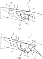
Fig. 1 shows a wing system in a neutral position. -
Fig. 2 shows the wing system ofFig. 1 with a flow body in a downward deflected position. -
Fig. 3 shows the wing system ofFigs. 1 and 2 with the flow body in an upward deflected position. -
Fig. 4 shows an aircraft having a wing system according toFigs. 1 to 3 . -
Fig. 1 shows awing system 2 having amain wing body 4, a trailingedge flap 6 as a flow body and acover panel 8. In this illustration, the components are in a neutral position and form a closed wing contour. Themain wing body 4 is a rigid structure, which is exemplarily attached to a wing box arranged in a fuselage of an aircraft (not shown). The structure and shape of themain wing body 4 is not relevant in the context of the invention. - In this exemplary embodiment, a
support structure 10 is rigidly attached on themain wing body 4 and extends in a downwardly, rearwardly facing direction. Thesupport structure 10 is illustrated as a simple triangle, which is strictly simplified. Instead, thesupport structure 10 may be a spatial framework structure, which is used for holding a first joint 12 in a certain position. - The
flap 6 is arranged at a rear end of themain wing body 4 and adds to themain wing body 4 to complete the outer shape of thewing system 2. In this exemplary embodiment, a connectingstructure 14 is rigidly attached to anunderside 16 of theflap 6. In the neutral position shown inFig. 1 , the connecting structure points downwardly and forwardly. At adistal end 18 of the connectingstructure 14, the connectingstructure 14 is connected to the first joint 12. Hence, the combination of connectingstructure 14 andflap 6 can swivel around an axis defined by the first joint 12. The flap may be driven through an actuator (not shown), which is coupled with themain wing body 4 or thesupport structure 10 and the connectingstructure 14 or another point on theflap 6. - The
main wing body 4 comprises a cut-out 20 at its upper side, in which thecover panel 8 is arranged. It extends from aforward end 22 to arearward end 24, which is directly on an upper side of theflap 6. The upper side of thewing system 2 is completely closed at least in the neutral position. This means, that the upper skin of themain wing body 4, of thecover panel 8 and of theflap 6 constitute a continuous, closed surface. - It is preferred that the
cover panel 8 follows the motion of theflap 6. For this, asecond link 26 is attached to an underside of thecover panel 8. Thesecond link 26 may be shaped as illustrated inFig. 1 , i.e. it comprises a mainlyperpendicular section 28 and a mainlyparallel section 30. The terms perpendicular and parallel relate to a coverpanel chord axis 33. Thesecond link 26 comprises a second joint 32, which is arranged at adistal end 34 of thesecond link 26. In the neutral position, the second joint 32 is arranged substantially below a trailingedge 24 of thecover panel 8 and under theflap 6. - For an interconnection of
flap 6 andsecond link 26, afirst link 36 is provided, which extends from the second joint 32 to a third joint 38, which is positioned at the underside of theflap 6. Hence, if theflap 6 is moved, the third joint 38 moves in a swiveling motion around the first joint 12 and consequently, the second joint 32 is moved accordingly. In order for thecover panel 8 to move, it is supported to themain wing body 4 to limit its motion. For example, this may be conducted by a further rotary joint (not shown). -
Fig. 2 shows thewing system 2 with the flap being extended about 40°. Here, the connectingstructure 14 is swiveled about 40° around the first joint 12 and thefirst link 36 pushes the second joint 32 in a slightly forward position. Hence, thecover panel 8 follows the motion and swivels slightly downwards. The upper surface of thewing system 2 has a roughly continuous surface with at least oneslot 40 between the flap and thecover panel 8. The size of theslot 40 may be adjusted by a suitable design of thesupport structure 10 and the connectingstructure 14. - In
Fig. 3 , theflap 6 is moved in an upward direction about roughly 20°. Here, thecover panel 8 is pushed further forward to avoid a damage through theflap 6 and also creates anarrow slot 42. During this motion, thefirst link 36 pulls the second joint 32 into a forward direction. - Finally,
Fig. 4 shows anaircraft 44 having twowing systems 2 installed to afuselage 46. As clear from this illustration, the drawings inFigs. 1 to 3 only show a cross section. As theflap 6 or another type of flow body extends in a spanwise direction,further support structures 10,first links 36,first joints 12,second joints 32 andthird joints 38 may be present to support theflap 6. - In addition, it should be pointed out that "comprising" does not exclude other elements or steps, and "a" or "an" does not exclude a plural number. Furthermore, it should be pointed out that characteristics or steps which have been described with reference to one of the above exemplary embodiments may also be used in combination with other characteristics or steps of other exemplary embodiments described above. Reference characters in the claims are not to be interpreted as limitations.
Claims (15)
- A wing system (2) for an aircraft (44), comprising:- a main wing body (4),- a movable flow body (6),- a cover panel (8),- a support structure (10) attached to the main wing body (4), and- a first link (36) swivably coupled to the flow body (6) with a first end of the first link (36),wherein the support structure (10) protrudes through the contour of the main wing body (4),
wherein flow body (6) is positioned downstream of the main wing body (4),
wherein the flow body (6) is swivably coupled to a first joint (12) at an end of the support structure (10), such that the flow body (6) is swivable around the first joint (12) from a neutral position into upwards or downwards deflected positions,
wherein the cover panel (8) is positioned (2) between the main wing body (4) and the flow body (6),
wherein the cover panel (8) is movably coupled to the main wing body (4) and swivably coupled to a second end of the first link (36) to follow the motion of the flow body (6) at least partially, and
wherein the main wing body (4), the cover panel (8) and the flow body (6) are designed to create a closed wing contour at least in the neutral position. - The wing system (2) of claim 1,
wherein the support structure (10) protrudes downwards from a bottom side of the main wing body (4). - The wing system (2) of claim 1 or 2,
wherein the support structure (10) is designed such that the first joint (12) is arranged forward the flow body (6) and underneath the cover panel (8) in the neutral position. - The wing system (2) of any of the preceding claims,
wherein the support structure (10) is rigidly attached to the main wing body (4). - The wing system (2) of any of the preceding claims,
further comprising a connecting structure (14), which is attached to an underside of the flow body (6) and coupled to the first joint (12). - The wing system (2) of claim 5,
wherein the connecting structure (14) is rigidly attached to the flow body (6). - The wing system (2) of any of the preceding claims,
further comprising a second link (26), which is rigidly attached to an underside of the cover panel (8) and swivably connected to the first link (36) by a second joint (32), which is arranged at a distal end of the second link (26). - The wing system (2) of claim 7,
wherein the second link (26) extends downwards and rearwards from the underside of the cover panel (8). - The wing system (2) of claim 7 or 8,
wherein the second joint (32) is positioned below the flow body (6) at least in the neutral position. - The wing system (2) of any of the claims 7 to 9,
wherein the second link (26) at least partially extends parallel to a cover panel chord (33). - The wing system (2) of any of the claims 7 to 10,
wherein the first joint (12) is arranged forward of the second joint (32) in the neutral position. - The wing system (2) of any of the claims 7 to 11,
wherein the first link (36) is swivably coupled to the flow body (6) at a third joint (38), which is arranged at an underside of the flow body (6),
wherein the third joint (38) is arranged directly above the second joint (32) or displaced in a rearward direction along 25% of a length of the flow body chord at a maximum in the neutral position. - The wing system (2) of any of the preceding claims,
wherein a flow body chord and the first link enclose an angle of 75 to 105 degrees in the neutral position. - The wing system (2) of any of the preceding claims,
further comprising an actuator, which is coupled with the main wing body (4) and the flow body (6) to move the flow body (6) and the cover panel (8) concurrently. - Aircraft (44), comprising a wing system (2) of any of claims 1 to 14.
Applications Claiming Priority (1)
| Application Number | Priority Date | Filing Date | Title |
|---|---|---|---|
| DE102018121182 | 2018-08-30 |
Publications (1)
| Publication Number | Publication Date |
|---|---|
| EP3617058A1 true EP3617058A1 (en) | 2020-03-04 |
Family
ID=67439027
Family Applications (1)
| Application Number | Title | Priority Date | Filing Date |
|---|---|---|---|
| EP19188512.8A Withdrawn EP3617058A1 (en) | 2018-08-30 | 2019-07-26 | A wing system for an aircraft with a flow body and a cover panel |
Country Status (4)
| Country | Link |
|---|---|
| US (1) | US11352122B2 (en) |
| EP (1) | EP3617058A1 (en) |
| CN (1) | CN110871885B (en) |
| BR (1) | BR102019017576A2 (en) |
Cited By (2)
| Publication number | Priority date | Publication date | Assignee | Title |
|---|---|---|---|---|
| CN117566088A (en) * | 2023-11-23 | 2024-02-20 | 中国航空研究院 | Variable camber wing rib and manufacturing method |
| US12428133B2 (en) | 2022-02-28 | 2025-09-30 | Airbus Operations Gmbh | Wing for an aircraft |
Families Citing this family (3)
| Publication number | Priority date | Publication date | Assignee | Title |
|---|---|---|---|---|
| CN112699488B (en) * | 2020-12-29 | 2024-02-13 | 中国航空工业集团公司西安飞机设计研究所 | A method for determining the position of the spatial motion pair of a mechanism |
| CN113830286B (en) * | 2021-09-18 | 2023-02-03 | 中国商用飞机有限责任公司 | Aileron actuation structure and wing comprising an aileron actuation structure |
| KR102939770B1 (en) | 2023-08-04 | 2026-03-13 | 한남대학교 산학협력단 | Fowler flap structure in aircraft |
Citations (7)
| Publication number | Priority date | Publication date | Assignee | Title |
|---|---|---|---|---|
| US2556326A (en) * | 1945-04-09 | 1951-06-12 | Charles H Grant | Airplane flap with slot controller |
| US2772058A (en) * | 1951-05-10 | 1956-11-27 | Charles H Grant | Aircraft wing with means to increase lift through control of air flow |
| EP1787905A2 (en) * | 2005-11-21 | 2007-05-23 | The Boeing Company | Aircraft trailing edge devices, including devices having forwardly positioned hinge lines, and associated methods |
| US7243881B2 (en) * | 2003-06-03 | 2007-07-17 | The Boeing Company | Multi-function trailing edge devices and associated methods |
| US20070176051A1 (en) * | 2005-04-27 | 2007-08-02 | Good Mark S | Actuation device positioning systems and associated methods, including aircraft spoiler droop systems |
| EP2669189A1 (en) * | 2012-05-29 | 2013-12-04 | The Boeing Company | Rotary actuated high lift gapped aileron |
| EP2808250A1 (en) | 2013-05-28 | 2014-12-03 | Airbus Operations GmbH | Aircraft flap system with aileron functionality |
Family Cites Families (12)
| Publication number | Priority date | Publication date | Assignee | Title |
|---|---|---|---|---|
| US4120470A (en) * | 1976-09-28 | 1978-10-17 | The Boeing Company | Efficient trailing edge system for an aircraft wing |
| US4353517A (en) * | 1980-10-07 | 1982-10-12 | The Boeing Company | Flap assembly for aircraft wing |
| USRE32907E (en) * | 1981-09-28 | 1989-04-18 | The Boeing Company | Airfoil flap assembly with flap track member |
| US4702442A (en) * | 1984-12-06 | 1987-10-27 | The Boeing Company | Aircraft trailing edge flap apparatus |
| US7338018B2 (en) * | 2005-02-04 | 2008-03-04 | The Boeing Company | Systems and methods for controlling aircraft flaps and spoilers |
| DE102007036996A1 (en) * | 2007-08-06 | 2009-02-19 | Airbus Deutschland Gmbh | High-lift system for an aircraft |
| DE102009011662A1 (en) * | 2009-03-04 | 2010-09-09 | Airbus Deutschland Gmbh | Wing of an aircraft and arrangement of a wing with a device for influencing the flow |
| US9061753B2 (en) * | 2012-11-29 | 2015-06-23 | The Boeing Company | Hinged panel operation systems and methods |
| US9878774B2 (en) * | 2014-09-19 | 2018-01-30 | The Boeing Company | System and method for operating a droop panel using a pin joint linkage assembly |
| US10144502B2 (en) | 2016-03-09 | 2018-12-04 | The Boeing Company | Aerodynamic structures having lower surface spoilers |
| BR102016020505B1 (en) * | 2016-09-05 | 2022-08-02 | Embraer S.A | AIRCRAFT FLAPS PANELS DEFLECTION MECHANISM |
| EP3301018A1 (en) * | 2016-09-30 | 2018-04-04 | Airbus Operations GmbH | System for driving and guiding of a multifunctional trailing edge control surface on an aircraft |
-
2019
- 2019-07-26 EP EP19188512.8A patent/EP3617058A1/en not_active Withdrawn
- 2019-08-23 BR BR102019017576-1A patent/BR102019017576A2/en not_active IP Right Cessation
- 2019-08-28 CN CN201910801444.8A patent/CN110871885B/en active Active
- 2019-08-29 US US16/554,963 patent/US11352122B2/en active Active
Patent Citations (7)
| Publication number | Priority date | Publication date | Assignee | Title |
|---|---|---|---|---|
| US2556326A (en) * | 1945-04-09 | 1951-06-12 | Charles H Grant | Airplane flap with slot controller |
| US2772058A (en) * | 1951-05-10 | 1956-11-27 | Charles H Grant | Aircraft wing with means to increase lift through control of air flow |
| US7243881B2 (en) * | 2003-06-03 | 2007-07-17 | The Boeing Company | Multi-function trailing edge devices and associated methods |
| US20070176051A1 (en) * | 2005-04-27 | 2007-08-02 | Good Mark S | Actuation device positioning systems and associated methods, including aircraft spoiler droop systems |
| EP1787905A2 (en) * | 2005-11-21 | 2007-05-23 | The Boeing Company | Aircraft trailing edge devices, including devices having forwardly positioned hinge lines, and associated methods |
| EP2669189A1 (en) * | 2012-05-29 | 2013-12-04 | The Boeing Company | Rotary actuated high lift gapped aileron |
| EP2808250A1 (en) | 2013-05-28 | 2014-12-03 | Airbus Operations GmbH | Aircraft flap system with aileron functionality |
Cited By (2)
| Publication number | Priority date | Publication date | Assignee | Title |
|---|---|---|---|---|
| US12428133B2 (en) | 2022-02-28 | 2025-09-30 | Airbus Operations Gmbh | Wing for an aircraft |
| CN117566088A (en) * | 2023-11-23 | 2024-02-20 | 中国航空研究院 | Variable camber wing rib and manufacturing method |
Also Published As
| Publication number | Publication date |
|---|---|
| US20200070954A1 (en) | 2020-03-05 |
| BR102019017576A2 (en) | 2020-03-10 |
| CN110871885A (en) | 2020-03-10 |
| CN110871885B (en) | 2026-01-30 |
| US11352122B2 (en) | 2022-06-07 |
Similar Documents
| Publication | Publication Date | Title |
|---|---|---|
| US11352122B2 (en) | Wing system for an aircraft with a flow body and a cover panel | |
| US10899431B2 (en) | System for driving and guiding of a multifunctional trailing edge control surface on an aircraft | |
| US8056865B2 (en) | Mechanism for changing the shape of a control surface | |
| EP2572978B1 (en) | Aircraft flap mechanism having compact large fowler motion providing multiple cruise positions | |
| CA2793044C (en) | Wing variable camber trailing edge tip | |
| CN105711807B (en) | Baffle driven by trailing edge control device | |
| CN105711813B (en) | Trailing edge device with bell crank mechanism | |
| RU2429163C2 (en) | Aircraft system | |
| EP2148813B1 (en) | Aircraft | |
| EP3176075B1 (en) | Aircraft wing assembly comprising a wing fairing drive assembly | |
| US9079655B2 (en) | System for increasing controllability for an aircraft | |
| EP2851287A1 (en) | Trailing edge actuator system and associated method | |
| US11591067B2 (en) | Rotating double trapped roller auxiliary track mechanism | |
| EP3597531B1 (en) | System for driving a flap arrangement between a retracted position and an extended position | |
| EP3594108A1 (en) | System for driving a flap arrangement between a retracted position and an extended position | |
| JP2011518711A (en) | Transverse coupling device for holding and guiding at least one aerodynamic body with respect to the main wing of an aircraft, and a wing and an aircraft having such a lateral coupling device | |
| CN107878732B (en) | System for driving and guiding trailing edge control surfaces | |
| EP4303122A1 (en) | Wing for an aircraft | |
| EP4269232B1 (en) | Fairing attachment system for a wing of an aircraft, aircraft wing and method for mounting a fairing device | |
| CN116176829A (en) | Aerodynamic control surface assembly | |
| GB2568743A (en) | System for an aircraft wing | |
| WO2024091205A1 (en) | A control surface movement mechanism | |
| EP4608715A1 (en) | A control surface movement mechanism |
Legal Events
| Date | Code | Title | Description |
|---|---|---|---|
| PUAI | Public reference made under article 153(3) epc to a published international application that has entered the european phase |
Free format text: ORIGINAL CODE: 0009012 |
|
| STAA | Information on the status of an ep patent application or granted ep patent |
Free format text: STATUS: THE APPLICATION HAS BEEN PUBLISHED |
|
| AK | Designated contracting states |
Kind code of ref document: A1 Designated state(s): AL AT BE BG CH CY CZ DE DK EE ES FI FR GB GR HR HU IE IS IT LI LT LU LV MC MK MT NL NO PL PT RO RS SE SI SK SM TR |
|
| AX | Request for extension of the european patent |
Extension state: BA ME |
|
| STAA | Information on the status of an ep patent application or granted ep patent |
Free format text: STATUS: THE APPLICATION IS DEEMED TO BE WITHDRAWN |
|
| 18D | Application deemed to be withdrawn |
Effective date: 20200905 |